

Page 1
FormNo.3382-138RevA
Groundsmaster
®
4300-DTraction
Unit
ModelNo.30859N—SerialNo.314000001andUp
Registeratwww.T oro.com.
OriginalInstructions(EN)
*3382-138*A
Page 2
WARNING
CALIFORNIA
Proposition65Warning
whichsignalsahazardthatmaycauseseriousinjuryordeath
ifyoudonotfollowtherecommendedprecautions.
Thisproductcontainsachemicalorchemicals
knowntotheStateofCaliforniatocausecancer,
birthdefects,orreproductiveharm.
Dieselengineexhaustandsomeofits
constituentsareknowntotheStateof
Californiatocausecancer,birthdefects,
andotherreproductiveharm.
Important:Thisengineisnotequippedwithaspark
arrestermufer.ItisaviolationofCaliforniaPublic
ResourceCodeSection4442touseoroperatetheengine
onanyforest-covered,brush-covered,orgrass-covered
land.Otherstatesorfederalareasmayhavesimilarlaws.
Introduction
Thismachineisaride-on,rotary-bladelawnmowerintended
tobeusedbyprofessional,hiredoperatorsincommercial
applications.Itisprimarilydesignedforcuttinggrass
onwell-maintainedlawnsinparks,sportselds,andon
commercialgrounds.Itisnotdesignedforcuttingbrush,
mowinggrassandothergrowthalongsidehighways,orfor
agriculturaluses.
Figure1
1.Safetyalertsymbol
Thismanualuses2otherwordstohighlightinformation.
Importantcallsattentiontospecialmechanicalinformation
andNoteemphasizesgeneralinformationworthyofspecial
attention.
Readthisinformationcarefullytolearnhowtooperateand
maintainyourproductproperlyandtoavoidinjuryand
productdamage.Youareresponsibleforoperatingthe
productproperlyandsafely.
YoumaycontactT orodirectlyatwww .Toro.comforproduct
andaccessoryinformation,helpndingadealer,ortoregister
yourproduct.
Wheneveryouneedservice,genuineT oroparts,oradditional
information,contactanAuthorizedServiceDealerorToro
CustomerServiceandhavethemodelandserialnumbersof
yourproductready.Themodelandserialnumbersareona
platemountedontheleftsideoftheframeunderthefoot
rest.Writethenumbersinthespaceprovided.
ModelNo.
SerialNo.
Thismanualidentiespotentialhazardsandhassafety
messagesidentiedbythesafetyalertsymbol(Figure1),
©2014—TheToro®Company
8111LyndaleAvenueSouth
Bloomington,MN55420
Contactusatwww.Toro.com.
2
PrintedintheUSA.
AllRightsReserved
Page 3

Contents
Introduction..................................................................2
Safety...........................................................................4
SafeOperatingPractices...........................................4
ToroRidingMowerSafety........................................6
SafetyandInstructionalDecals.................................7
Setup...........................................................................10
1AdjustingtheTirePressure....................................10
2AdjustingtheStepHeight.....................................10
3AdjustingtheControlArmPosition........................11
4RemovetheShippingBlocksandPins.....................11
5InstallingRearWeights.........................................12
ProductOverview.........................................................14
Controls...............................................................14
Specications........................................................17
Attachments/Accessories........................................17
Operation....................................................................18
CheckingtheEngineOilLevel.................................18
CheckingtheCoolingSystem...................................19
AddingFuel...........................................................19
CheckingtheHydraulicFluid...................................20
ChecktheTorqueoftheWheelNuts.........................21
BleedingtheFuelSystem.........................................21
StartingandStoppingtheEngine..............................22
PushingorTowingtheMachine................................22
JackingPoints........................................................23
TieDowns............................................................23
UnderstandingtheDiagnosticLight..........................24
DiagnosticAceDisplay...........................................24
CheckingtheInterlockSwitches...............................24
HydraulicValveSolenoidFunctions..........................26
OperatingTips......................................................26
Maintenance.................................................................27
RecommendedMaintenanceSchedule(s)......................27
DailyMaintenanceChecklist....................................28
ServiceIntervalChart.............................................29
Lubrication...............................................................29
GreasingtheBearingsandBushings..........................29
EngineMaintenance..................................................31
ServicingtheAirCleaner.........................................31
ServicingtheEngineOilandFilter............................31
AdjustingtheThrottle.............................................32
FuelSystemMaintenance...........................................32
DrainingtheFuelTank...........................................32
CheckingtheFuelLinesandConnections..................32
ServicingtheWaterSeparator..................................32
FuelPick-upTubeScreen........................................33
BleedingAirfromtheFuelInjectors..........................33
ElectricalSystemMaintenance....................................34
ServicingtheBattery...............................................34
Fuses....................................................................34
DriveSystemMaintenance.........................................35
AdjustingtheTractionDriveforNeutral....................35
AdjustingtheRearWheelToe-in..............................35
CoolingSystemMaintenance......................................36
RemovingDebrisfromtheCoolingSystem................36
BrakeMaintenance....................................................37
AdjustingtheServiceBrakes....................................37
AdjustingtheParkingBrake....................................37
BeltMaintenance......................................................38
TensioningtheAlternatorBelt.................................38
HydraulicSystemMaintenance....................................38
ChangingtheHydraulicFluid...................................38
ReplacingtheHydraulicFilters.................................39
CheckingtheHydraulicLinesandHoses....................39
ChangingtheCounterbalanceSettings.......................40
HydraulicSystemTestPorts.....................................40
Storage........................................................................41
PreparingtheTractionUnit.....................................41
PreparingtheEngine..............................................41
3
Page 4

Safety
ThismachinemeetsorexceedsISOstandard5395:1990
andANSIB71.4-2004specicationsineffectattimeof
production,whenequippedwithrearweight.Referto
thesectioninthismanualonInstallingRearWeight.
Improperuseormaintenancebytheoperatoror
ownercanresultininjury.Toreducethepotential
forinjury,complywiththesesafetyinstructionsand
alwayspayattentiontothesafetyalertsymbol,which
meansCaution,Warning,orDanger—personalsafety
instruction.Failuretocomplywiththeinstructionmay
resultinpersonalinjuryordeath.
SafeOperatingPractices
ThefollowinginstructionsareadaptedfromtheCEN
standardEN836:1997,ISOstandard5395:1990,andANSI
B71.4-2012.
Preparation
•Whilemowing,alwayswearsubstantialfootwear,long
trousers,hardhat,safetyglasses,andearprotection.Long
hair,looseclothing,orjewelrymaygettangledinmoving
parts.Donotoperatetheequipmentwhenbarefootor
wearingopensandals.
•Thoroughlyinspecttheareawheretheequipmentisto
beusedandremoveallobjectswhichmaybethrownby
themachine.
•Replacefaultysilencers/mufers.
•Evaluatetheterraintodeterminewhataccessoriesand
attachmentsareneededtoproperlyandsafelyperform
thejob.Onlyuseaccessoriesandattachmentsapproved
bythemanufacturer.
•Checkthattheoperator'spresencecontrols,safety
switchesandshieldsareattachedandfunctioning
properly.Donotoperateunlesstheyarefunctioning
properly.
Training
•Readtheoperator'smanualandothertrainingmaterial
carefully.Befamiliarwiththecontrols,safetysigns,and
theproperuseoftheequipment.
•Neverallowchildrenorpeopleunfamiliarwiththese
instructionstouseorservicethemower.Local
regulationsmayrestricttheageoftheoperator.
•Nevermowwhilepeople,especiallychildren,orpetsare
nearby.
•Keepinmindthattheoperatororuserisresponsiblefor
accidentsorhazardsoccurringtootherpeopleortheir
property.
•Donotcarrypassengers.
•Alldriversandmechanicsshouldseekandobtain
professionalandpracticalinstruction.Theowneris
responsiblefortrainingtheusers.Suchinstructionshould
emphasize:
–theneedforcareandconcentrationwhenworking
withride-onmachines;
–controlofaride-onmachineslidingonaslopewill
notberegainedbytheapplicationofthebrake.The
mainreasonsforlossofcontrolare:
◊insufcientwheelgrip;
◊beingdriventoofast;
◊inadequatebraking;
◊thetypeofmachineisunsuitableforitstask;
◊lackofawarenessoftheeffectofground
conditions,especiallyslopes;
◊incorrecthitchingandloaddistribution.
•Theowner/usercanpreventandisresponsiblefor
accidentsorinjuriesoccurringtohimselforherself,other
people,orproperty.
SafeHandlingofFuels
•Toavoidpersonalinjuryorpropertydamage,use
extremecareinhandlinggasoline.Gasolineisextremely
ammableandthevaporsareexplosive.
•Extinguishallcigarettes,cigars,pipes,andothersources
ofignition.
•Useonlyanapprovedfuelcontainer.
•Neverremovefuelcaporaddfuelwiththeengine
running.
•Allowenginetocoolbeforerefueling.
•Neverrefuelthemachineindoors.
•Neverstorethemachineorfuelcontainerwherethereis
anopename,spark,orpilotlightsuchasonawater
heateroronotherappliances.
•Neverllcontainersinsideavehicleoronatruckor
trailerbedwithaplasticliner.Alwaysplacecontainerson
thegroundawayfromyourvehiclebeforelling.
•Removeequipmentfromthetruckortrailerandrefuelit
ontheground.Ifthisisnotpossible,thenrefuelsuch
equipmentwithaportablecontainer,ratherthanfroma
fueldispensernozzle.
•Keepthenozzleincontactwiththerimofthefueltank
orcontaineropeningatalltimesuntilfuelingiscomplete.
Donotuseanozzlelockopendevice.
•Iffuelisspilledonclothing,changeclothingimmediately.
•Neveroverllfueltank.Replacefuelcapandtighten
securely.
Operation
•Donotoperatetheengineinaconnedspacewhere
dangerouscarbonmonoxidefumescancollect.
•Mowonlyindaylightoringoodarticiallight.
4
Page 5

•Beforeattemptingtostarttheengine,disengageallblade
attachmentclutches,shiftintoneutral,andengagethe
parkingbrake.
•Rememberthereisnosuchthingasasafeslope.Travel
ongrassslopesrequiresparticularcare.Toguardagainst
overturning:
–donotstoporstartsuddenlywhengoingupor
downhill;
–machinespeedsshouldbekeptlowonslopesand
duringtightturns;
–stayalertforhumpsandhollowsandotherhidden
hazards;
–Donotturnsharply.Usecarewhenreversing.
–Usecounterweight(s)orwheelweightsasidentied
intheoperator'smanual.
•Stayalertforholesintheterrainandotherhiddenhazards.
•Watchoutfortrafcwhencrossingornearroadways.
•Stopthebladesrotatingbeforecrossingsurfacesother
thangrass.
•Whenusinganyattachments,neverdirectdischargeof
materialtowardbystandersnorallowanyonenearthe
machinewhileinoperation.
•Neveroperatethemachinewithdamagedguards,shields,
orwithoutsafetyprotectivedevicesinplace.Besureall
interlocksareattached,adjustedproperly ,andfunctioning
properly.
•Donotchangetheenginegovernorsettingsorover-speed
theengine.Operatingtheengineatexcessivespeedmay
increasethehazardofpersonalinjury.
•Beforeleavingtheoperator'sposition:
–stoponlevelground;
–disengagethepowertake-offandlowerthe
attachments;
–changeintoneutralandsettheparkingbrake;
–stoptheengineandremovethekey.
•Disengagedrivetoattachmentswhentransportingornot
inuse.
•Stoptheengineanddisengagedrivetoattachment:
–beforerefuelling;
–beforeremovingthegrasscatcher/catchers;
–beforemakingheightadjustmentunlessadjustment
canbemadefromtheoperator'sposition.
–beforeclearingblockages;
–beforechecking,cleaningorworkingonthemower;
–afterstrikingaforeignobjectorifanabnormal
vibrationoccurs.Inspectthemowerfordamage
andmakerepairsbeforerestartingandoperatingthe
equipment.
•Reducethethrottlesettingduringenginerun-outand,if
theengineisprovidedwithashut-offvalve,turnthefuel
offattheconclusionofmowing.
•Keephandsandfeetawayfromthecuttingdecks.
•Lookbehindanddownbeforebackinguptobesureof
aclearpath.
•Slowdownandusecautionwhenmakingturnsand
crossingroadsandsidewalks.
•Donotoperatethemowerundertheinuenceofalcohol
ordrugs.
•Lightningcancausesevereinjuryordeath.Iflightning
isseenorthunderisheardinthearea,donotoperate
themachine;seekshelter.
•Usecarewhenloadingorunloadingthemachineintoa
trailerortruck.
•Usecarewhenapproachingblindcorners,shrubs,trees,
orotherobjectsthatmayobscurevision.
MaintenanceandStorage
•Keepallnuts,boltsandscrewstighttobesurethe
equipmentisinsafeworkingcondition.
•Neverstoretheequipmentwithfuelinthetankinsidea
buildingwherefumesmayreachanopenameorspark.
•Allowtheenginetocoolbeforestoringinanyenclosure.
•Toreducetherehazard,keeptheengine,
silencer/mufer,batterycompartmentandfuelstorage
areafreeofgrass,leaves,orexcessivegrease.
•Keepallpartsingoodworkingconditionandallhardware
andhydraulicttingstightened.Replaceallwornor
damagedpartsanddecals.
•Ifthefueltankhastobedrained,dothisoutdoors.
•Becarefulduringadjustmentofthemachinetoprevent
entrapmentofthengersbetweenmovingbladesand
xedpartsofthemachine.
•Disengagedrives,lowerthecuttingdecks,setparking
brake,stopengineandremovekeyfromignition.Wait
forallmovementtostopbeforeadjusting,cleaningor
repairing.
•Cleangrassanddebrisfromcuttingdecks,drives,
silencers/mufers,andenginetohelppreventres.Clean
upoilorfuelspillage.
•Usejackstandstosupportcomponentswhenrequired.
•Carefullyreleasepressurefromcomponentswithstored
energy.
•Disconnectbatterybeforemakinganyrepairs.Disconnect
thenegativeterminalrstandthepositivelast.Reconnect
positiverstandnegativelast.
•Keephandsandfeetawayfrommovingparts.Ifpossible,
donotmakeadjustmentswiththeenginerunning.
•Chargebatteriesinanopenwellventilatedarea,away
fromsparkandames.Unplugchargerbeforeconnecting
ordisconnectingfrombattery.W earprotectiveclothing
anduseinsulatedtools.
Hauling
•Usecarewhenloadingorunloadingthemachineintoa
trailerortruck.
5
Page 6

•Usefullwidthrampsforloadingmachineintotraileror
truck.
•Tiethemachinedownsecurelyusingstraps,chains,cable,
orropes.Bothfrontandrearstrapsshouldbedirected
downandoutwardfromthemachine
ToroRidingMowerSafety
ThefollowinglistcontainssafetyinformationspecictoToro
productsorothersafetyinformationthatyoumustknowthat
isnotincludedintheCEN,ISO,orANSIstandard.
Thisproductiscapableofamputatinghandsandfeetand
throwingobjects.Alwaysfollowallsafetyinstructionsto
avoidseriousinjuryordeath.
Useofthisproductforpurposesotherthanitsintendeduse
couldprovedangeroustouserandbystanders.
WARNING
Engineexhaustcontainscarbonmonoxide,which
isanodorless,deadlypoisonthatcankillyou.
Donotrunengineindoorsorinanenclosedarea.
•Knowhowtostoptheenginequickly .
•Donotoperatethemachinewhilewearingtennisshoes
orsneakers.
•Wearingsafetyshoesandlongpantsisadvisableand
requiredbysomelocalordinancesandinsurance
regulations.
•Handlefuelcarefully.Wipeupanyspills.
•Checkthesafetyinterlockswitchesdailyforproper
operation.Ifaswitchshouldfail,replacetheswitch
beforeoperatingthemachine.
•Beforestartingtheengine,sitontheseat.
•Usingthemachinedemandsattention.Topreventloss
ofcontrol:
–Donotdriveclosetosandtraps,ditches,creeks,or
otherhazards.
•Iftheenginestallsorlosesheadwayandcannotmakeit
tothetopofaslope,donotturnthemachinearound.
Alwaysbackslowly,straightdowntheslope.
•Whenapersonorpetappearsunexpectedlyinornearthe
mowingarea,stopmowing.Carelessoperation,combined
withterrainangles,ricochets,orimproperlypositioned
guardscanleadtothrownobjectinjuries.Donotresume
mowinguntiltheareaiscleared.
MaintenanceandStorage
•Makesureallhydrauliclineconnectorsaretightandall
hydraulichosesandlinesareingoodconditionbefore
applyingpressuretothesystem.
•Keepyourbodyandhandsawayfrompinholeleaksor
nozzlesthatejecthydraulicuidunderhighpressure.
Usepaperorcardboard,notyourhands,tosearchfor
leaks.Hydraulicuidescapingunderpressurecanhave
sufcientforcetopenetratetheskinandcauseserious
injury.Seekimmediatemedicalattentionifuidis
injectedintoskin.
•Beforedisconnectingorperforminganyworkonthe
hydraulicsystem,allpressureinthesystemmustbe
relievedbystoppingtheengineandloweringthecutting
decksandattachmentstotheground.
•Checkallfuellinesfortightnessandwearonaregular
basis.Tightenorrepairthemasneeded.
•Iftheenginemustberunningtoperformamaintenance
adjustment,keephands,feet,clothing,andanypartsof
thebodyawayfromthecuttingdecks,attachments,and
anymovingparts.Keepeveryoneaway.
•Toensuresafetyandaccuracy,haveanAuthorizedToro
Distributorcheckthemaximumenginespeedwitha
tachometer.
•Ifmajorrepairsareeverneededorifassistanceisdesired,
contactanAuthorizedToroDistributor.
•UseonlyToro-approvedattachmentsandreplacement
parts.Thewarrantymaybevoidedifusedwith
unapprovedattachments.
–Reducespeedwhenmakingsharpturns.Avoid
suddenstopsandstarts.
–Whennearorcrossingroads,alwaysyieldthe
right-of-way.
–Applytheservicebrakeswhengoingdownhillto
keepforwardspeedslowandtomaintaincontrolof
themachine.
•Raisethecuttingdeckswhendrivingfromoneworkarea
toanother.
•Donottouchtheengine,silencer/mufer,orexhaust
pipewhiletheengineisrunningorsoonafterithas
stoppedbecausetheseareascouldbehotenoughtocause
burns.
6
Page 7
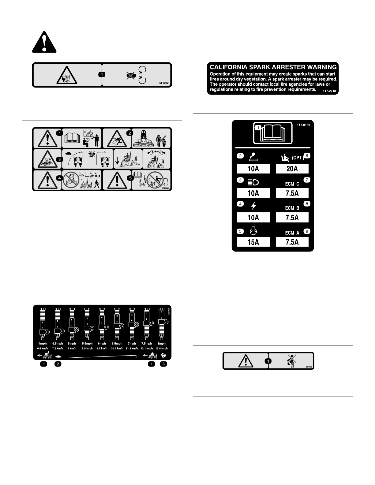
SafetyandInstructionalDecals
Safetydecalsandinstructionsareeasilyvisibletotheoperatorandarelocatednearanyareaofpotential
danger.Replaceanydecalthatisdamagedorlost.
93-7272
1.Cutting/dismembermenthazard;fan—stayawayfromoving
parts.
110-8869
117–2718
1.Warning—readtheOperator'sManual,donotoperatethis
machineunlessyouaretrained.
2.Thrownobjecthazard—keepbystandersasafedistance
fromthemachine.
3.Tippinghazard—slowmachinebeforeturning,donotturn
athighspeeds;lowerthecuttingunitwhendrivingdown
slopes;usearolloverprotectionsystemandweartheseat
belt.AlwayswearaseatbeltwhenaROPSisinplace.
4.Warning—donotparkthemachineonslopes;engagethe
parkingbrake,lowerthecuttingdecks,stoptheengineand
removetheignitionkeybeforeleavingthemachine.
5.Warning—readtheOperator'sManual,donottowthe
machine.
110-8921
1.Tractionunitspeed
2.Slow
3.Fast
117–0169
1.ReadtheOperator'sManual.
2.Powerpoint—10amp
3.Headlights—10amp
4.Power—10amp
5.Enginestart—15amp
6.Optionalairrideseatsuspension—10amp
7.EnginecomputermanagementC—10amp
8.EnginecomputermanagementB—10amp
9.EnginecomputermanagementA—10amp
93–6689
1.Danger—donotsitontheplasticshroud.
7
Page 8
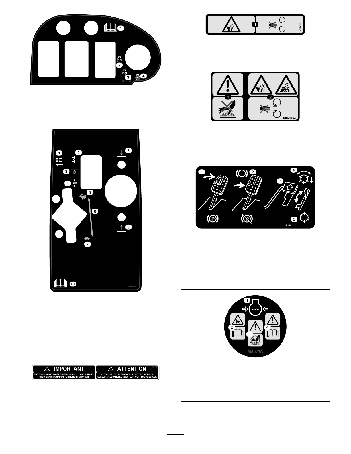
93-6681
1.Cutting/dismemberment—hazard,fan-stayawayfrom
movingparts.
117–2385
1.ReadtheOperators
Manual.
2.Engine—start4.Engine—stop
3.Engine—preheat
106-6754
1.Warning—donottouchthehotsurface.
2.Cutting/dismembermenthazard,fanandentanglement
hazard,belt—stayawayfrommovingparts.
110-0986
1.Pressthebrakepedalandparkingbrakepedaltosetthe
parkingbrake.
2.Pressthebrakepedaltoapplythebrake.
3.Pressthetractionpedaltomovethemachineforward.
4.Reelenabledmode
5.Transportmode
117–0170
1.Headlights
2.Engage
3.Powertake-off(PTO)
4.Disengage9.Raisecuttingunits
5.Fast
6.Continuousvariable
throttlesetting
7.Slow
8.Lowercuttingunits
10.ReadtheOperator's
Manual.
112-5019
1.Enginecoolantunder
2.Explosionhazard—read
8
pressure.
theOperator'sManual.
106-6755
3.Warning—donottouchthe
hotsurface.
4.Warning—readthe
Operator'sManual.
Page 9
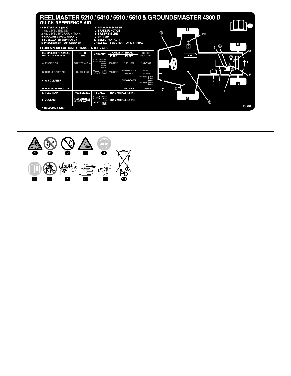
1.ReadtheOperator'sManual.
BatterySymbols
Someorallofthesesymbolsareonyourbattery
117-0168
1.Explosionhazard
2.Nore,opename,or
smoking.
3.Causticliquid/chemical
burnhazard
4.Weareyeprotection9.Flusheyesimmediately
5.ReadtheOperator's
Manual.
6.Keepbystandersasafe
7.Weareyeprotection;
8.Batteryacidcancause
10.Containslead;donot
distancefromthebattery.
explosivegasescan
causeblindnessandother
injuries
blindnessorsevereburns.
withwaterandgetmedical
helpfast.
discard.
9
Page 10

Setup
LooseParts
Usethechartbelowtoverifythatallpartshavebeenshipped.
ProcedureDescription
1
2
3
4
5
Nopartsrequired
Nopartsrequired
Nopartsrequired
Nopartsrequired
Rearweights(quantityvarieswith
conguration).
MediaandAdditionalParts
Description
Operator'sManual
EngineOperator'sManual
PartsCatalog
OperatorTrainingMaterial
Note:Determinetheleftandrightsidesofthemachine
fromthenormaloperatingposition.
Qty.
Qty.
–
–
–
–
Varies
1
1
1
1
Reviewbeforeoperatingmachine
Adjustthetirepressure.
Adjustthestepheight.
Adjustthecontrolarmposition.
Removeshippingblocksandpins
Installrearweights(orderfromyour
ToroDistributor).
Use
Use
1
AdjustingtheTirePressure
NoPartsRequired
Procedure
Thetiresareover-inatedforshipping.Therefore,release
someoftheairtoreducethepressure.Correctairpressurein
thefrontandreartiresis83to103kPa(12to15psi).
Important:Maintainevenpressureinalltirestoensure
uniformcontactwiththeturf.
2
AdjustingtheStepHeight
NoPartsRequired
Procedure
Theheightofthestepscanbeadjustedfortheoperators
comfort.
1.Removethe2boltsandnutssecuringthestepbrackets
tothetractionunitframe(Figure2)
10
Page 11
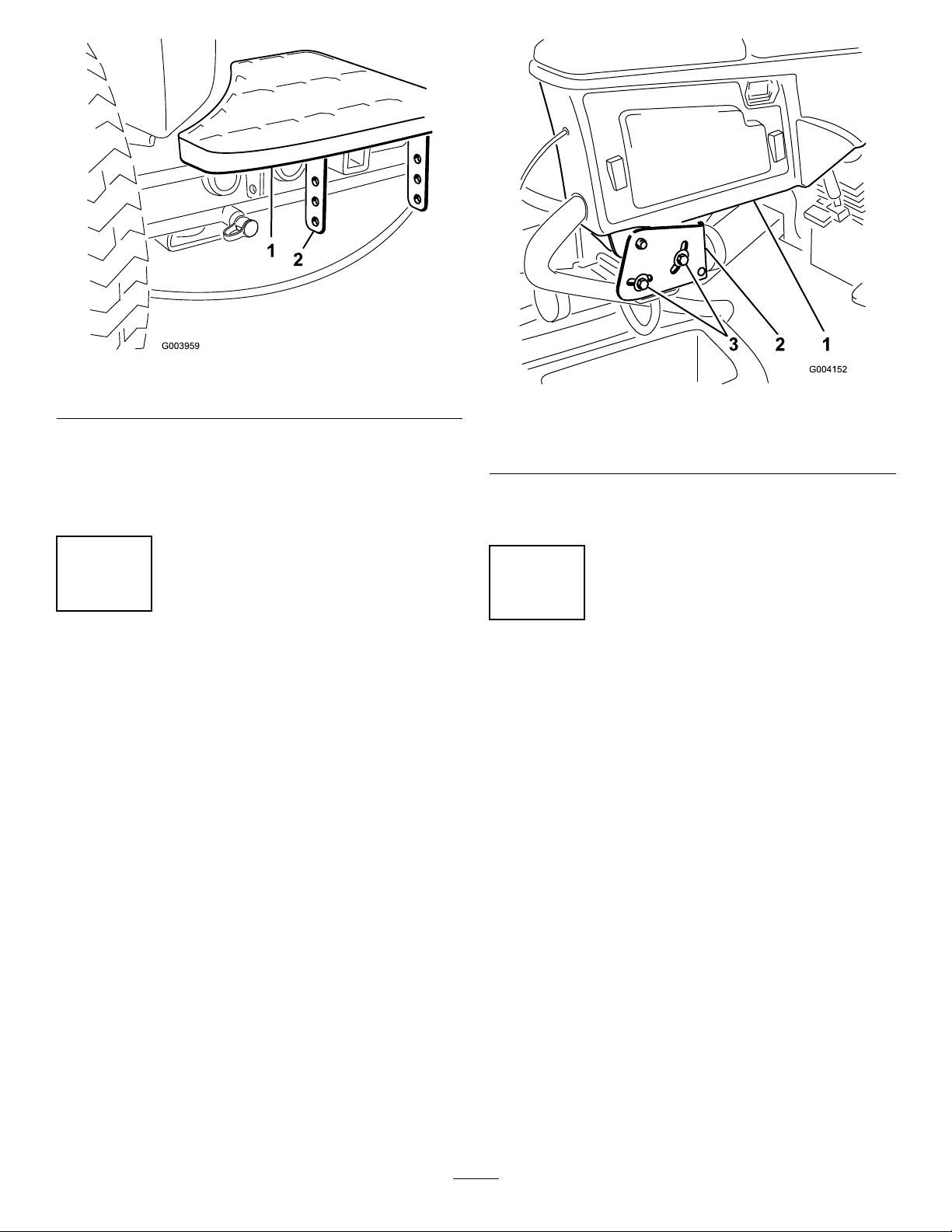
Figure2
1.Step2.Stepbrackets
2.Raiseorlowerthesteptothedesiredheightand
re-securethebracketstotheframewiththe2bolts
andnuts.
3.Repeattheprocedureontheotherstep.
3
AdjustingtheControlArm Position
NoPartsRequired
Procedure
Thecontrolarmpositioncanbeadjustedfortheoperators
comfort.
1.Loosenthe2boltssecuringthecontrolarmtothe
retainingbracket(Figure3).
Figure3
1.Controlarm3.Bolts(2)
2.Retainingbrackets
2.Rotatethecontrolarmtothedesiredpositionand
tightenthe2bolts.
4
RemovetheShippingBlocks andPins
NoPartsRequired
Procedure
1.Removeanddiscardtheshippingblocksfromthe
cuttingdecks.
2.Removeanddiscardtheshippingpinsfromthecutting
decksuspensionarms.Theshippingpinsstabilizethe
cuttingdecksduringshippingandmustberemoved
beforeoperation.
11
Page 12
5
InstallingRearWeights
Partsneededforthisprocedure:
Varies
Rearweights(quantityvarieswithconguration).
Procedure
TheGroundsmaster4300–DTractionUnitcomplieswithISOstandard5395:1990andANSIB71.4-2004Standardswhen
equippedwithrearweightsand/or90lbofcalciumchlorideballastisaddedtorearwheels.Usethefollowingchartsto
determinethecombinationsofweightsrequiredforyourconguration.OrderpartsfromyourlocalAuthorizedToro
Distributor.
WeightP/N110-8985-03
Conguration
BaseUnit6
WithRecycler
Kit
WithSunshade
orCooltops
With4Post
ROPS&
Sunshadeor
Cooltops
Numberofweightstomeet
ANSI(US)standards
90lbcalciumchloride*N/AN/A
90lbcalciumchloride*
90lbcalciumchloride*
*Installtubesinsidethereartiresbeforeaddingcalciumchloride.
Fasteners(2eachrequired)
forweights
3231–34CarriageBolt
104–8301Nut
3231–7CarriageBolt
104–8301Nut
3231–7CarriageBolt
104–8301Nut
WeightLocation
3ontopofbumperand3
underbumper
1ontopofbumperand3
underbumper
1ontopofbumperand3
underbumper
Important:Alwaysinstalltubesinsidethereartiresbeforecalciumchlorideisinstalled.Ifapunctureoccursina
tirewithcalciumchloride,removethemachinefromtheturfareaasquicklyaspossible.Topreventpossibledamage
totheturf,immediatelysoaktheaffectedareawithwater.
Usethefollowingproceduretomounttheappropriateamountofweight(seeweightcharts)tothetoporbottomofthe
rearbumperasshowninFigure4.
12
Page 13
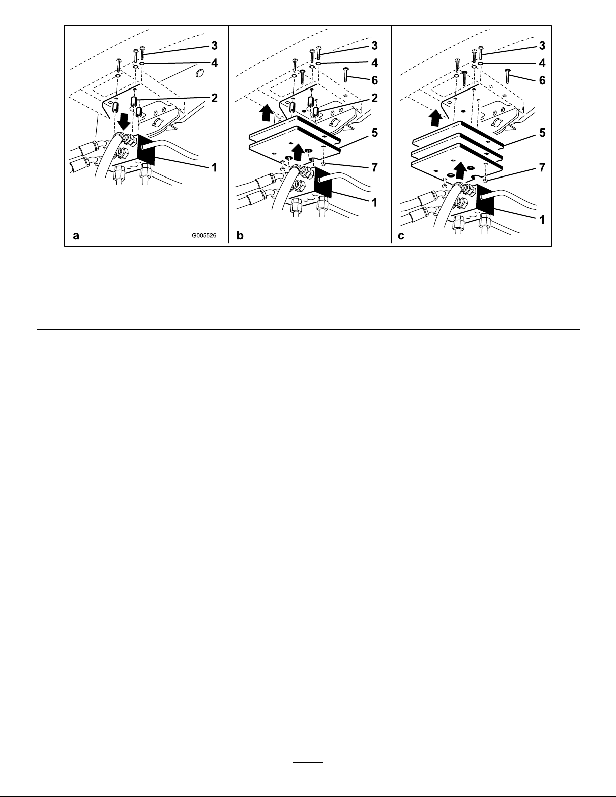
Figure4
1.Tractionmanifold5.Weight(s)
2.Spacers6.Carriagebolt
3.Bolts7.Nut
4.Washers
•Removethe3bolts,washers,andspacerssecuringthetractionmanifoldtothebottomoftherearbumper(Figure4a).
•Positiontheappropriateamountofweightonthetopand/orbottomoftherearbumper.
•Mounttheweight(s)andthetractionmanifoldtothebumperwiththe3bolts,washersandspacerspreviouslyremoved
(Figure4b).
Note:Donotusethespacerswheninstallingmorethantwoweightsunderthebumper(Figure4c).
•Securetheouteredgesoftheweight(s)tothebumperwith2carriageboltsandnuts(Figure4c).
13
Page 14
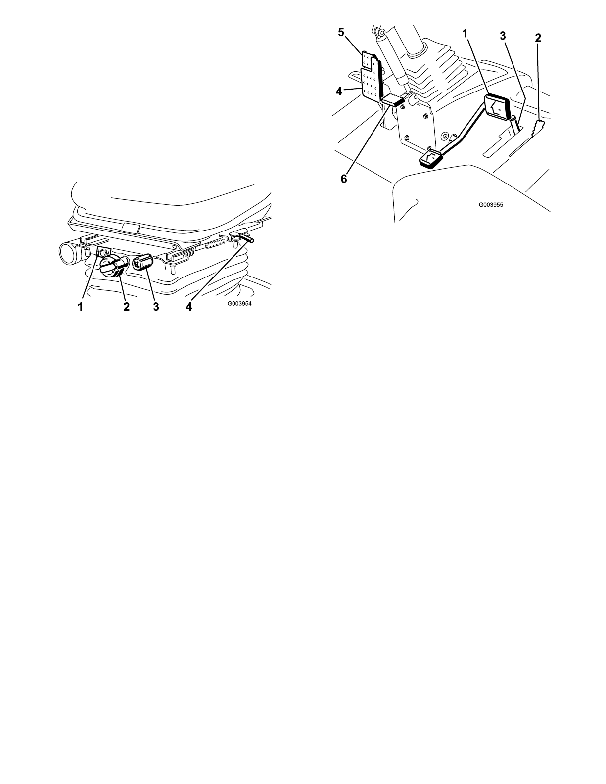
ProductOverview
Controls
SeatAdjustingKnobs
Theseatadjustinglever(Figure5)allowsyoutoadjustthe
seatforeandaft.Theweightadjustingknobadjuststheseat
fortheoperator'sweight.Theweightgaugeindicateswhen
theseatisadjustedtotheweightoftheoperator.Theheight
adjustingknobadjuststheseatfortheoperator'sheight.
Figure6
1.Tractionpedal4.Brakepedal
2.Mowspeedlimiter5.Parkingbrake
3.Spacers
6.Tiltsteeringpedal
Figure5
1.Weightgauge3.Heightadjustingknob
2.Weightadjustingknob
4.Adjustinglever(foreand
aft)
TractionPedal
Thetractionpedal(Figure6)controlstheforwardandreverse
operation.Pressthetopofthepedaltomoveforwardandthe
bottomtomoverearward.Groundspeeddependsonhow
faryoupressthepedal.Fornoload,maximumgroundspeed,
fullypressthepedalwhilethethrottleisintheFastposition.
Tostop,reducefootpressureonthetractionpedalandallow
ittoreturntothecenterposition.
MowSpeedLimiter
Whenthemowspeedlimiter(Figure6)isippedupitwill
controlthemowspeedandallowthecuttingdeckstobe
engaged.Eachspaceradjuststhemowingspeedby½mile
perhour.Themorespacersyouhave,onthetopofthebolt
thesloweryouwillgo.Fortransport,ipbackthemowspeed
limiterandyouwillhavemaximumtransportspeed.
BrakePedal
Pressthebrakepedal(Figure6)tostopthemachine.
ParkingBrake
Toengagetheparkingbrake,(Figure6)pushdownonthe
brakepedalandpressthetopforwardtolatch.Toreleasethe
parkingbrake,pressthebrakepedaluntiltheparkingbrake
latchretracts.
TiltSteeringPedal
Totiltthesteeringwheeltowardsyou,pressthefootpedal
(Figure6)down,andpullthesteeringtowertowardyouto
themostcomfortablepositionandthenreleasethepedal.
ThrottleControl
Movethethrottlecontrol(Figure7)forwardtoincreasethe
enginespeedandrearwardtodecreasespeed.
14
Page 15

G003956
1
2
3
4
5
6
7
8
9
10
Figure7
1.Throttlecontrol6.Enginecoolant
2.Enable/disableswitch
3.Glowplugindicatorlight8.Chargeindicator
4.Enginecoolant
temperaturewarning
light
5.Diagnosticlight
7.Engineoilpressure
9.Keyswitch
10.Lowermow/raisecontrol
temperaturegauge
warninglight
lever
GlowPlugIndicatorLight
Thislight(Figure7)illuminateswhentheglowplugsare
preheating.
EngineOilPressureWarningLight
Thislight(Figure7)indicatesdangerouslylowengineoil
pressure.
ChargeIndicator
Thechargeindicator(Figure7)illuminateswhenthesystem
chargingcircuitmalfunctions.
Enable/DisableSwitch
Usetheenable/disableswitch(Figure7)inconjunctionwith
thelowermow/raisecontrollevertooperatethemowers.
Themowerscannotbeloweredwhenthemow/transport
leverisinthetransportposition.
HourMeter
Thehourmeter(Figure8)showsthetotalhoursthatthe
machinehasbeenoperated.
KeySwitch
Thekeyswitch(Figure7)hasthreepositions:Off,
On/Preheat,andStart.
EngineCoolantTemperatureWarning
Light
Thislight(Figure7)illuminatesandthemowersshutdown
whentheenginecoolantreachesahightemperature.Ifthe
enginetemperaturecontinuestorise,theenginewillshut
down.
EngineCoolantTemperatureGauge
Duringnormaloperatingconditionsthegauge(Figure7)
shouldbeinthegreenrange.Checkthecoolingsystemifthe
gaugegoestotheyelloworredrange.
DiagnosticLight
Itwillilluminateshouldasystemfaultberecognized.
1.Hourmeter
HydraulicFilterRestrictionIndicator
Withtheenginerunningatnormaloperatingtemperature,
viewtheindicator(Figure9),itshouldbeintheGreenzone.
WhentheindicatorisintheRedzone,changethehydraulic
lters.
Figure8
LowerMow/RaiseControlLever
Thislever(Figure7)raisesandlowersthecuttingdecks
andalsostartsandstopsthemowerswhenthemowersare
enabledinthemowmode.
15
Page 16

1.Hydrauliclterrestrictionindicator
Figure9
FuelGauge
Thefuelgauge(Figure10)showstheamountoffuelinthe
tank.
Figure10
Figure11
1.Headlightswitch
PowerPoint
Thepowerpointisa12voltpowersupplyforelectronic
devices(Figure12).
1.Fueltankcap
2.Fuelgauge
HeadlightSwitch
Pivottheswitchdownwardtoturnontheheadlights(Figure
11).
Figure12
1.Powerpoint
16
Page 17

Specications
Note:Specicationsanddesignaresubjecttochange
withoutnotice.
TransportWidth
Widthofcut229cm(90inches)
Length
Height
Fueltankcapacity
Transportspeed
Mowingspeed
Netweight*
*Withcuttingdecksanduids
226cm(89inches)
320cm(126inches)
218cm(86inches)
51liters(13.5USgallons)
0–16kph(0–10mph)
0–13kph(0–8mph)
1,412kg(3,1 14lb)
Attachments/Accessories
AselectionofToroapprovedattachmentsandaccessoriesis
availableforusewiththemachinetoenhanceandexpand
itscapabilities.ContactyourAuthorizedServiceDealeror
Distributororgotowww .Toro.comforalistofallapproved
attachmentsandaccessories.
17
Page 18

Operation
Note:Determinetheleftandrightsidesofthemachine
fromthenormaloperatingposition.
CAUTION
Ifyouleavethekeyintheignitionswitch,someone
couldaccidentlystarttheengineandseriously
injureyouorotherbystanders.
Lowerthecuttingdeckstotheground,setthe
parkingbrakeandremovethekeyfromtheignition
switchbeforeservicingormakingadjustmentsto
themachine.
CheckingtheEngineOilLevel
Theengineisshippedwithoilinthecrankcase;however,the
oillevelmustbecheckedbeforeandaftertheengineisrst
started.
Crankcasecapacityisapproximately5.2liters(5.5quarts)
withthelter.
Usehigh-qualityengineoilthatmeetsthefollowing
specications:
•APIClassicationLevelRequired:CH-4,CI-4orhigher
•Preferredoil:SAE15W-40(above0degreesF)
•Alternateoil:SAE10W-30or5W-30(alltemperatures)
ToroPremiumEngineoilisavailablefromyourdistributorin
either15W -40or10W-30viscosity .
1.Parkthemachineonalevelsurface,stoptheengine,
settheparkingbrakeandremovethekeyfromthe
ignitionswitch.
2.Openthehood.
3.Removethedipstick,wipeitclean,andinstallit(Figure
13).
Figure13
1.Dipstick
4.Removedipstickandcheckoillevelondipstick.
TheoillevelshouldbeuptotheFullmark.
5.IftheoillevelisbelowtheFullmark,removethell
Figure14)andaddoiluntillevelreachestheFull
cap(
markondipstick.
1.Oilllcap
Donotoverll.
Important:Besuretokeeptheengineoillevel
betweentheupperandlowerlimitsontheoil
gauge.Enginefailuremayoccurasaresultofover
llingorunderllingtheengineoil.
6.Installtheoilllcapandclosethehood.
18
Figure14
Page 19

CheckingtheCoolingSystem
AddingFuel
Cleandebrisoffofthescreen,oilcooler,andfrontofthe
radiatordailyandmoreoftenifconditionsareextremely
dustyanddirty.RefertothesectiononRemovingDebris
fromtheCoolingSysteminMaintenance.
Thecoolingsystemislledwitha50/50solutionofwater
andpermanentethyleneglycolantifreeze.Checkthelevelof
coolantintheexpansiontankatthebeginningofeachday
beforestartingtheengine.Thecapacityofthecoolingsystem
is9.5liters(10quarts).
CAUTION
Iftheenginehasbeenrunning,thepressurized,hot
coolantcanescapeandcauseburns.
•Donotopentheradiatorcapwhentheengine
isrunning.
•Usearagwhenopeningtheradiatorcap,and
openthecapslowlytoallowsteamtoescape.
1.Checkthelevelofcoolantintheexpansiontank
(Figure15).
Thecoolantlevelshouldbebetweenthemarksonthe
sideofthetank.
Useonlyclean,freshdieselfuelorbiodieselfuelswithlow
(<500ppm)orultralow(<15ppm)sulfurcontent.The
minimumcetaneratingshouldbe40.Purchasefuelin
quantitiesthatcanbeusedwithin180daystoensurefuel
freshness.
Fueltankcapacity:51liters(13.5gallons)
Usesummergradedieselfuel(No.2-D)attemperatures
above-7°C(20°F)andwintergrade(No.1-DorNo.
1-D/2-Dblend)belowthattemperature.Useofwintergrade
fuelatlowertemperaturesprovideslowerashpointand
coldowcharacteristicswhichwilleasestartingandreduce
fuellterplugging.
Useofsummergradefuelabove-7°C(20°F)willcontribute
towardlongerfuelpumplifeandincreasedpowercompared
towintergradefuel.
Important:Donotusekeroseneorgasolineinsteadof
dieselfuel.Failuretoobservethiscautionwilldamage
theengine.
WARNING
Fuelisharmfulorfatalifswallowed.Long-term
exposuretovaporscancauseseriousinjuryand
illness.
Figure15
1.Expansiontank
2.Ifthecoolantlevelislow,removetheexpansiontank
capandreplenishthesystem.Donotoverll.
•Avoidprolongedbreathingofvapors.
•Keepfaceawayfromnozzleandgastankor
conditioneropening.
•Keepfuelawayfromeyesandskin.
BiodieselReady
Thismachinecanalsouseabiodieselblendedfuelofup
toB20(20%biodiesel,80%petrodiesel).Thepetrodiesel
portionshouldbeloworultralowsulfur.Observethe
followingprecautions:
•Thebiodieselportionofthefuelmustmeetspecication
ASTMD6751orEN14214.
•TheblendedfuelcompositionshouldmeetASTMD975
orEN590.
•Paintedsurfacesmaybedamagedbybiodieselblends.
•UseB5(biodieselcontentof5%)orlesserblendsincold
weather.
•Monitorseals,hoses,gasketsincontactwithfuelasthey
maybedegradedovertime.
3.Installtheexpansiontankcap.
•Fuellterpluggingmaybeexpectedforatimeafter
convertingtobiodieselblended.
•Contactyourdistributorifyouwishformoreinformation
onbiodiesel.
19
Page 20

DANGER
Incertainconditions,fuelisextremelyammable
andhighlyexplosive.Areorexplosionfromfuel
canburnyouandothersandcandamageproperty.
•Fillthefueltankoutdoors,inanopenarea,when
theengineiscold.Wipeupanyfuelthatspills.
•Neverllthefueltankinsideanenclosedtrailer.
•Neversmokewhenhandlingfuel,andstayaway
fromanopenameorwherefuelfumesmaybe
ignitedbyaspark.
•Storefuelinanapprovedcontainerandkeepit
outofthereachofchildren.Neverbuymore
thana180-daysupplyoffuel.
•Donotoperatewithoutentireexhaustsystemin
placeandinproperworkingcondition.
DANGER
Incertainconditionsduringfueling,static
electricitycanbereleasedcausingasparkwhich
canignitethefuelvapors.Areorexplosionfrom
fuelcanburnyouandothersandcandamage
property.
•Alwaysplacefuelcontainersonthegroundaway
fromyourvehiclebeforelling.
Figure16
1.Fueltankcap2.Fuelgauge
4.Fillthetankuntilthelevelistothebottomoftheller
neckwithdieselfuel.
5.Installfueltankcaptightlyafterllingtank.
Note:Ifpossible,llthefueltankaftereachuse.This
willminimizepossiblebuildupofcondensationinside
thefueltank.
•Donotllfuelcontainersinsideavehicleoron
atruckortrailerbedbecauseinteriorcarpets
orplastictruckbedlinersmayinsulatethe
containerandslowthelossofanystaticcharge.
•Whenpractical,removeequipmentfromthe
truckortrailerandrefueltheequipmentwithits
wheelsontheground.
•Ifthisisnotpossible,thenrefuelsuch
equipmentonatruckortrailerfromaportable
container,ratherthanfromafueldispenser
nozzle.
•Ifafueldispensernozzlemustbeused,keepthe
nozzleincontactwiththerimofthefueltank
orcontaineropeningatalltimesuntilfuelingis
complete.
1.Parkthemachineonalevelsurface.
2.Usingacleanrag,cleanareaaroundfueltankcap.
3.Removecapfromthefueltank(
Figure16).
CheckingtheHydraulicFluid
Themachinesreservoirislledatthefactorywith
approximately37.8liters(10U .S.gallons)ofhighquality
hydraulicuid.Checkthelevelofthehydraulicuid
beforetheengineisrststartedanddailythereafter.The
recommendedreplacementuidisasfollows:
ToroPremiumAllSeasonHydraulicFluid(Availablein5
gallonpailsor55gallondrums.SeepartscatalogorT oro
distributorforpartnumbers.)
Alternateuids:IftheTorouidisnotavailable,other
uidsmaybeusedprovidedtheymeetallthefollowing
materialpropertiesandindustryspecications.W edonot
recommendtheuseofsyntheticuid.Consultwithyour
lubricantdistributortoidentifyasatisfactoryproductNote:
Torowillnotassumeresponsibilityfordamagecausedby
impropersubstitutions,souseonlyproductsfromreputable
manufacturerswhowillstandbehindtheirrecommendation.
HighViscosityIndex/LowPourPointAnti-wearHydraulic
Fluid,ISOVG46
MaterialProperties:
Viscosity,ASTMD445cSt@40°C44to48
ViscosityIndexASTM
D2270
PourPoint,ASTMD97-34°Fto-49°F
cSt@100°C7.9to8.5
140to160
20
Page 21

IndustrySpecications:
VickersI-286-S(QualityLevel),VickersM-2950-S
(QualityLevel),DenisonHF-0
ChecktheTorqueoftheWheel Nuts
Important:TheISOVG46Multigradeuidhasbeen
foundtoofferoptimalperformanceinawiderangeof
temperatureconditions.Foroperationinconsistently
highambienttemperatures,65°F(18°C)to120°F
(49°C),ISOVG68hydraulicuidmayofferimproved
performance.
PremiumBiodegradableHydraulicFluid-MobilEAL
EnviroSyn46H
Important:MobilEALEnviroSyn46Histheonly
syntheticbiodegradableuidapprovedbyT oro.This
uidiscompatiblewiththeelastomersusedinToro
hydraulicsystemsandissuitableforawide-range
oftemperatureconditions.Thisuidiscompatible
withconventionalmineraloils,butformaximum
biodegradabilityandperformancethehydraulicsystem
shouldbethoroughlyushedofconventionaluid.The
oilisavailablein19liters(5gallon)containersor55
gallondrumsfromyourMobilDistributor.
Important:Manyhydraulicuidsarealmostcolorless,
makingitdifculttospotleaks.Areddyeadditive
forthehydraulicsystemoilisavailablein20ml(2/3
oz.)bottles.Onebottleissufcientfor15-22liters(4-6
gallons)ofhydraulicoil.Orderpartno.44-2500from
yourauthorizedT orodistributor.
1.Positionmachineonalevelsurface,lowerthecutting
decksandstoptheengine.
2.Cleanareaaroundllerneckandcapofhydraulictank
(
Figure17).
TorquethewheelnutstoTorquethewheellugnutsto94to
122N-m(70to90ft-lb)after1-4hoursofoperationand
againafter10hoursofoperation.T orqueevery250hours
thereafter.
WARNING
Failuretomaintainpropertorqueofthewheelnuts
couldresultinpersonalinjury.
BleedingtheFuelSystem
Youmustbleedthefuelsystembeforestartingtheengineif
anyofthefollowingsituationshaveoccurred:
•Initialstartupofanewmachine.
•Enginehasceasedrunningduetolackoffuel.
•Maintenancehasbeenperformeduponfuelsystem
components;i.e.,lterreplaced,separatorserviced,etc.
DANGER
Undercertainconditions,dieselfuelandfuel
vaporsarehighlyammableandexplosive.Are
orexplosionfromfuelcanburnyouandothersand
cancausepropertydamage.
•Useafunnelandllthefueltankoutdoors,in
anopenarea,whentheengineisoffandiscold.
Wipeupanyfuelthatspills.
Figure17
1.Hydraulictankcap
3.Removecap/dipstickfromllerneckandwipeitwith
acleanrag.Insertdipstickintollerneck;thenremove
itandchecklevelofuid.Fluidlevelshouldbewithin
operatingrangeondipstick.Donotoverll.
4.Iflevelislow,addappropriateuidtoraiselevelto
fullmark.
5.Installcap/dipstickontollerneck.
•Donotllthefueltankcompletelyfull.Add
fueltothefueltankuntilthelevelis6to13mm
(1/4to1/2inch)belowthebottomoftheller
neck.Thisemptyspaceinthetankallowsthe
fueltoexpand.
•Neversmokewhenhandlingfuel,andstayaway
fromanopenameorwherefuelfumesmaybe
ignitedbyaspark.
•Storefuelinaclean,safety-approvedcontainer
andkeepthecapinplace.
1.Parkthemachineonalevelsurfaceandensurethatthe
fueltankisatleasthalffull.
2.Openthehood.
3.Opentheairbleedscrewonthefuelinjectionpump
(
Figure18)witha12mmwrench.
21
Page 22

Figure18
1.Bleedscrew
4.TurnthekeyintheignitionswitchtotheOnposition.
Theelectricfuelpumpwillbeginoperation,thereby
forcingairoutaroundtheairbleedscrew .Leavethe
keyintheOnpositionuntilasolidstreamoffuelows
outaroundthescrew .
5.TightenthescrewandturnthekeytotheOffposition.
Note:Normally,theengineshouldstartaftertheabove
bleedingproceduresarefollowed.However,ifenginedoes
notstart,airmaybetrappedbetweeninjectionpumpand
injectors;refertoBleedingAirfromtheInjectors.
StartingandStoppingthe
preheatingisrequired,turnkeytotheOffpositionand
thentotheOn/Preheatposition.Repeatthisprocess
asrequired.
4.Runtheengineatlowidlespeeduntilitwarmsup.
StoppingtheEngine
1.MoveallcontrolstoNeutral,settheparkingbrake,
movethethrottletothelowidlepositionandallowthe
enginetoreachlowidlespeed.
Important:Allowtheenginetoidlefor5
minutesbeforeshuttingitoffafterafullload
operation.Failuretodosomayleadtotroubleon
aturbo-chargedengine.
2.TurnthekeytotheOffpositionandremoveitfrom
theswitch.
PushingorTowingthe Machine
Inanemergency,themachinecanbemovedbyactuatingthe
bypassvalveinthevariabledisplacementhydraulicpumpand
pushingortowingthemachine.
Important:Donotpushortowthemachinefasterthan
3-4.8km/h(2-3mph)becauseinternaltransmission
damagemayoccur.Thebypassvalvemustbeopen
wheneverthemachineispushedortowed.
1.Thebypassvalveislocatedontheleftsideofthe
hydrostat(Figure19).Rotatethebolt1–1/2turnsto
openandallowoiltobypassinternally.Becauseuid
isbypassed,themachinecanbemovedslowlywithout
damagingthetransmission.
Engine
Important:Y oumustbleedthefuelsystembefore
startingtheengineifyouarestartingtheengineforthe
rsttime,theenginehasstoppedduetolackoffuel,or
youhaveperformedmaintenanceonthefuelsystem;
refertoBleedingtheFuelSystem.
StartingtheEngine
1.Sitontheseat,keepyourfootoffofthetractionpedal
sothatitisinNeutral,engagetheparkingbrake,set
thethrottletotheFastposition,andensurethatthe
Enable/DisableswitchisintheDisableposition.
2.TurntheignitionswitchtotheOn/Preheatposition.
Anautomatictimerwillcontroltheglowplugpreheat
for6seconds.
3.Afterpreheatingtheglowplugs,turnkeytotheStart
position.
Cranktheenginefornolongerthan15seconds.
Releasethekeywhentheenginestarts.Ifadditional
Figure19
1.Bypassvalve
2.Closethebypassvalvebeforestartingtheengine.
However,donotexceed7-11N-m(5-8ft.-lb)torque
toclosethevalve.
22
Page 23

Important:Runningtheenginewiththebypass
valveopenwillcausethetransmissiontooverheat.
JackingPoints
Note:Usejackstandstosupportthemachinewhenrequired.
•Front—rectangularpad,undertheaxletube,insideeach
fronttire(
Figure20).
Figure21
1.Fronttiedown
•Rear—eachsideofthemachineontherearframe(Figure
22).
Figure20
1.Frontjackingpoint
•Rear—rectangularaxletubeontherearaxle.
TieDowns
•Front—theholeintherectangularpad,undertheaxle
tube,insideeachfronttire(Figure21).
Figure22
1.Reartiedown
23
Page 24

UnderstandingtheDiagnostic
DiagnosticAceDisplay
Light
Themachineisequippedwithadiagnosticlightwhich
indicatesiftheelectroniccontrollersensesanelectronic
malfunction.Thediagnosticlightislocatedonthecontrol
arm(Figure23).Whentheelectroniccontrollerisfunctioning
correctlyandthekeyswitchismovedtotheOnposition,
thecontrollerdiagnosticlightwillturnONfor3seconds
andturnOFFtoindicatethelightisworkingproperly.If
themachinekillsthelightwillturnonsteadyuntilthekey
positionischanged.Thelightwillblinkifthecontroller
detectsamalfunctionintheelectricalsystem.Thelightwill
stopblinkingandautomaticallyresetwhenthekeyswitchis
turnedtotheOffpositiononcethefaulthasbeenresolved.
Themachineisequippedwithanelectroniccontrollerwhich
controlsmostmachinefunctions.Thecontrollerdetermines
whatfunctionisrequiredforvariousinputswitches(i.e.seat
switch,keyswitch,etc.)andturnsontheoutputstoactuate
solenoidsorrelaysfortherequestedmachinefunction.
Fortheelectroniccontrollertocontrolthemachineas
desired,eachoftheinputswitches,outputsolenoids,and
relaysmustbeconnectedandfunctioningproperly.
UsetheDiagnosticACEdisplaytohelpverifyandcorrect
electricalfunctionsofthemachine.
CheckingtheInterlock Switches
Thepurposeoftheinterlockswitchesistopreventthe
enginefromcrankingorstartingunlessthetractionpedalis
intheNeutralposition,theEnable/Disableswitchisinthe
Disableposition,andtheLowerMow/Raisecontrolisinthe
Neutralposition.Inaddition,theengineshouldstopwhen
thetractionpedalispressedwithoperatoroffoftheseatorif
theparkingbrakeisleftengaged.
Figure23
1.Diagnosticlight
Whenthecontrollerdiagnosticlightblinks,oneofthe
followingproblemshasbeendetectedbythecontroller:
•Oneoftheoutputshasbeenshorted.
•Oneoftheoutputsisopencircuited.
Usingthediagnosticdisplay,determinewhichoutputis
malfunctioning;refertoCheckingtheInterlockSwitches.
Ifthediagnosticlightisnotilluminatedwhenthekeyswitchis
intheOnposition,thisindicatesthattheelectroniccontroller
isnotoperating.Possiblecausesareasfollows:
•Loop-backisnotconnected.
•Thelightisburnedout.
•Fusesareblown.
•Itisnotfunctioningcorrectly.
CAUTION
Ifsafetyinterlockswitchesaredisconnectedor
damagedthemachinecouldoperateunexpectedly
causingpersonalinjury.
•Donottamperwiththeinterlockswitches.
•Checktheoperationoftheinterlockswitches
dailyandreplaceanydamagedswitchesbefore
operatingthemachine.
VerifyingtheInterlockSwitchFunction
1.Parkthemachineonalevelsurface,lowerthecutting
decks,stoptheengine,andengagetheparkingbrake.
2.Removetheaccesspanelfromthesideofthecontrol
arm.
3.Locatethewireharnessandconnectorsnearthe
controller(Figure24).
Checktheelectricalconnections,inputfuses,anddiagnostic
lightbulbtodeterminethemalfunction.Ensurethatthe
loop-backconnectorissecuredtothewireharnessconnector.
24
Page 25

willblinkonandoffwhencorrespondingswitchis
closed.Repeatthisforallswitchesthatyoucanchange
byhand.
9.IfaswitchisclosedandtheappropriateLEDdoesnot
turnon,checkallwiringandconnectionstotheswitch
and/orchecktheswitcheswithanohmmeter.Replace
anydefectiveswitchesandrepairanydefectivewiring.
Note:TheDiagnosticACEalsohastheabilitytodetect
whichoutputsolenoidsorrelaysareturnedon.Thisisa
quickwaytodetermineifamachinemalfunctioniselectrical
orhydraulic.
Figure24
1.Wireharnessandconnectors
4.Carefullyunplugloopbackconnectorfromharness
connector.
5.ConnecttheDiagnosticACEdisplayconnectortothe
harnessconnector(
Figure25).
Note:Makesurecorrectoverlaydecalispositioned
onDiagnosticACEdisplay.
VerifyingOutputFunction
1.Parkthemachineonalevelsurface,lowerthecutting
decks,stoptheengine,andengagetheparkingbrake.
2.Removetheaccesspanelfromthesideofthecontrol
arm.
3.Locatewireharnessandconnectorsnearcontroller.
4.Carefullyunplugloopbackconnectorfromharness
connector.
5.ConnecttheDiagnosticACEconnectortotheharness
connector.
Note:Makesurecorrectoverlaydecalispositioned
onDiagnosticACE.
6.TurnthekeyswitchtotheONposition,butdonot
startmachine.
Note:Theredtextontheoverlaydecalreferstoinput
switchesandthegreentextreferstooutputs.
7.The“outputsdisplayed”LED,onlowerrightcolumn
ofDiagnosticACE,shouldbeilluminated.Ifthe
“inputsdisplayed”LEDisilluminated,pressthetoggle
button,ontheDiagnosticACE,tochangetheLEDto
“outputsdisplayed”.
Figure25
1.DiagnosticACE
6.TurnthekeyswitchtotheOnposition,butdonot
startthemachine.
Note:Theredtextontheoverlaydecalreferstoinput
switchesandthegreentextreferstooutputs.
7.The“inputsdisplayed”LED,onthelowerright
columnoftheDiagnosticACE,shouldbeilluminated.
Ifthe“outputsdisplayed”LEDisilluminated,press
thetogglebutton,onDiagnosticACE,tochangeLED
to“inputsdisplayed”.
TheDiagnosticACEwillilluminatetheLEDassociated
witheachoftheinputswhenthatinputswitchisclosed.
8.Individually,changeeachoftheswitchesfromopen
toclosed(i.e.,sitonseat,engagetractionpedal,etc.),
andnotethattheappropriateLEDonDiagnosticACE
Note:Itmaybenecessarytotogglebetween“inputs
displayed”and“outputsdisplayed”severaltimestodo
thefollowingstep.Totogglebackandforth,press
thetogglebuttononce.Thismaybedoneasoftenas
required.Donotholdthebutton.
8.Sitontheseatandattempttooperatethedesired
functionofthemachine.Theappropriateoutput
LEDsshouldilluminatetoindicatethattheECMis
turningonthatfunction.
Note:IfthecorrectoutputLEDsdonotilluminate,verify
thattherequiredinputswitchesareinthenecessarypositions
toallowthatfunctiontooccur.V erifycorrectswitchfunction.
IftheoutputLEDsareonasspecied,butthemachinedoes
notfunctionproperly,thisindicatesanon-electricalproblem.
Repairasnecessary.
Note:Ifeachoutputswitchisinthecorrectpositionand
functioningcorrectly,buttheoutputLEDsarenotcorrectly
illuminated,thisindicatesanECMproblem.Ifthisoccurs,
contactyourToroDistributorforassistance.
25
Page 26

Important:TheDiagnosticACEdisplaymustnotbe
leftconnectedtothemachine.Itisnotdesignedto
withstandtheenvironmentofthemachine'severyday
use.WhendoneusingtheDiagnosticACE,disconnect
itfromthemachineandconnectloop-backconnector
toharnessconnector.Themachinewillnotoperate
withoutloopbackconnectorinstalledontheharness.
StoretheDiagnosticACEindry,securelocationinthe
shop,notonthemachine.
MowwhentheGrassisDry
Moweitherinthelatemorningtoavoidthedew ,whichcauses
grassclumping,orinlateafternoontoavoidthedamage
thatcanbecausedbydirectsunlightonthesensitive,freshly
mowedgrass.
SelecttheProperHeight-of-CutSetting
toSuitConditions
HydraulicValveSolenoid Functions
Usethelistbelowtoidentifyanddescribethedifferent
functionsofthesolenoidsinthehydraulicmanifold.Each
solenoidmustbeenergizedtoallowfunctiontooccur.
Solenoid
PRV2Frontmowercircuit
PRV1Rearmowercircuit
PRV
S1
S2
Lift/lowercuttingdecks
Lowercuttingdecks
Lowercuttingdecks
Function
OperatingTips
Familiarization
Beforemowinggrass,practiceoperatingthemachineinan
openarea.Startandstoptheengine.Operateinforward
andreverse.Lowerandraisethecuttingdecksandengage
anddisengagethemowers.Whenyoufeelfamiliarwiththe
machine,practiceoperatingupanddownslopesatdifferent
speeds.
WarningSystem
Ifawarninglightcomesonduringoperation,stopthe
machineimmediatelyandcorrecttheproblembefore
continuingoperation.Seriousdamagecouldoccurifyou
operatethemachinewithamalfunction.
Removeapproximatelyoneinchornomorethan1/3ofthe
grassbladewhencutting.Inexceptionallylushanddense
grassyoumayhavetoraisetheheight–of–cutsetting.
AlwaysStartMowingwithSharpBlades
Asharpbladecutscleanlyandwithouttearingorshredding
thegrassbladeslikeadullblade.Tearingandshredding
causesthegrasstoturnbrownattheedgeswhichimpairs
growthandincreasessusceptibilitytodiseases.Makesure
bladeisingoodconditionandafullsailispresent.
CheckConditionofDeck
Makesurethatthecuttingchambersareingoodcondition.
Straightenanybendsinthechambercomponentstoensure
thecorrectbladetip/chamberclearance.
AfterOperating
Toensureoptimumperformance,cleantheundersideof
mowerhousing.Ifyouallowresiduetobuildupinmower
housing,cuttingperformancewilldecrease.
Transport
MovetheEnable/DisableswitchtotheDisablepositionand
raisethecuttingdeckstothetransportposition.Movethe
Mow/Transportlevertothetransportposition.Becareful
whendrivingbetweenobjectssoyoudonotaccidentally
damagethemachineorcuttingdecks.Useextracarewhen
operatingthemachineonslopes.Driveslowlyandavoid
sharpturnsonslopestopreventrollovers.Lowerthecutting
deckswhengoingdownhillforsteeringcontrol.
Mowing
StarttheengineandmovethethrottletotheFastposition.
MovetheEnable/DisableswitchtotheEnablepositionand
usetheLowerMow/Raiselevertocontrolthecuttingdecks.
Tomoveforwardandcutgrass,pressthetractionpedal
forward.
Note:Allowtheenginetoidlefor5minutesbeforeshutting
itoffafterafullloadoperation.Failuretodosomayleadto
turbo-chargertrouble.
26
Page 27

Maintenance
Note:Determinetheleftandrightsidesofthemachinefromthenormaloperatingposition.
RecommendedMaintenanceSchedule(s)
MaintenanceService
Interval
Afterthersthour
Aftertherst8hours
Aftertherst10hours
Aftertherst50hours
Beforeeachuseordaily
Every50hours
Every100hours
Every150hours
MaintenanceProcedure
•T orquethewheellugnutsto94to122N-m(70to90ft-lb).
•Checktheconditionandtensionofthealternatorbelt.
•T orquethewheellugnutsto94to122N-m(70to90ft-lb).
•Changetheengineoilandlter.
•ChecktheengineRPM(idleandfullthrottle).
•Checktheengineoillevel.
•Checkthecoolingsystem.
•Checkthehydraulicuidlevel.
•Checktheoperationoftheinterlockswitches.
•Removedebrisfromthescreen,oilcoolers,andradiator(morefrequentlyindirty
operatingconditions).
•Checkthehydrauliclinesandhosesforleaks,kinkedlines,loosemountingsupports,
wear,loosettings,weatherdeterioration,andchemicaldeterioration.
•Greasethebearingsandbushings.(Greasethemimmediatelyaftereverywashing
regardlessoftheintervallisted.)
•Checktheconditionofandcleanthebattery.
•Checkthebatterycableconnections.
•Inspectthecoolingsystemhoses.
•Checktheconditionandtensionofthealternatorbelt.
•Changetheengineoilandlter.
Every200hours
Every250hours
Every400hours
Every800hours
Beforestorage
Every2years
•Drainmoisturefromthefuelandhydraulicuidtanks.
•T orquethewheellugnutsto94to122N-m(70to90ft-lb).
•Servicetheaircleaner.(Servicetheaircleanerearlieriftheaircleanerindicator
showsred.Serviceitmorefrequentlyinextremelydirtyordustyconditions.)
•Checkthefuellinesandconnectionsfordeterioration,damage,orlooseconnections.
•Replacethefuelltercanister .
•ChecktheengineRPM(idleandfullthrottle).
•Drainandcleanthefueltank
•Checktherearwheeltoe-in.
•Changethehydraulicuid.
•Changethehydrauliclters(sooneriftheserviceintervalindicatorisintheRed
zone).
•Packtherearwheelbearings
•Adjusttheenginevalves(refertotheengineOperator'sManual)
•Drainandcleanthefueltank
•Flushandreplacethecoolingsystemuid.
•Drainandushthehydraulictank.
•Replaceallmovinghoses.
27
Page 28

DailyMaintenanceChecklist
Duplicatethispageforroutineuse.
Fortheweekof: MaintenanceCheckItem
Mon.Tues.Wed.Thurs.Fri.
Checkthesafetyinterlockoperation.
Checkthebrakeoperation.
Checktheengineoilandfuellevel.
Drainthewater/fuelseparator.
Checktheairlterrestrictionindicator.
Checktheradiatorandscreenfordebris.
Checkunusualenginenoises.
Checkunusualoperatingnoises.
Checkthehydraulicsystemoillevel.
Checkthehydrauliclterindicator.
Checkhydraulichosesfordamage.
Checkforuidleaks.
Checkthetirepressure.
Checktheinstrumentoperation.
ChecktheHeightofCutadjustment
CheckConditionofBlades
Checkallgreasettingsforlubrication.
Touch-updamagedpaint.
1.Checktheglowplugandinjectornozzlesifhardstarting,excesssmoke,orroughrunningisnoted.
1
2
3
Sat.Sun.
2.Checkwiththeenginerunningandtheoilatoperatingtemperature
3.Immediatelyaftereverywashing,regardlessoftheintervallisted
NotationforAreasofConcern
Inspectionperformedby:
ItemDate
1
2
3
4
5
6
7
8
Important:Refertoyour
Note:LookingforanElectricalSchematicorHydraulicSchematicforyourmachine?Downloadafreecopyoftheschematicby
visitingwww .T oro.comandsearchingforyourmachinefromtheManualslinkonthehomepage.
Information
Engine Operator's Man ual
foradditionalmaintenanceprocedures.
28
Page 29

ServiceIntervalChart
Figure26
CAUTION
Ifyouleavethekeyintheignitionswitch,someonecouldaccidentlystarttheengineandseriouslyinjure
youorotherbystanders.
Removethekeyfromtheignitionbeforeyoudoanymaintenance.
Lubrication
GreasingtheBearingsand Bushings
Ifyouoperatethemachineundernormalconditions,lubricate
allgreasettingsforthebearingsandbushingsafterevery
50hoursofoperationwithNo.2GeneralPurposeLithium
BaseGrease.Lubricatebearingsandbushingsimmediately
aftereverywashing,regardlessoftheintervallisted.
Thegreasettinglocationsandquantitiesareasfollows:
•PumpdriveshaftU-joint(3)(
Figure27)
Figure28
Figure27
•Cuttingunitliftarmcylinders(2each)(Figure28)
29
Page 30

•Liftarmpivots(1each)(Figure28)
G011614
G011615
•Cuttingunitcarrierframepivot(1each)(Figure29)
Figure29
•Liftarmpivotshaft(1each)(Figure30)
•Axlesteeringpivot(1)(Figure32)
Figure32
•Steeringcylinderballjoints(2)andrearaxle(1)(Figure33)
Figure30
•Rearaxletierod(2)(Figure31)
Figure31
Figure33
•Brakepedal(1)(Figure34)
Figure34
30
Page 31

EngineMaintenance
ServicingtheAirCleaner
Checktheaircleanerbodyfordamagewhichcouldcausean
airleak.Replaceifdamaged.Checkthewholeintakesystem
forleaks,damageorloosehoseclamps.
Servicetheaircleanerlteronlywhentheserviceindicator
Figure35)requiresit.Changingtheairlterbeforeitis
(
necessaryonlyincreasesthechanceofdirtenteringtheengine
whenthelterisremoved.
Important:Besurethecoverisseatedcorrectlyand
sealswiththeaircleanerbody .
1.Releasethelatchessecuringtheaircleanercovertothe
aircleanerbody(Figure35).
5.Installthecoverorientingtherubberoutletvalveina
downwardposition—betweenapproximately5:00to
7:00whenviewedfromtheend.
6.Securethelatches.
ServicingtheEngineOiland Filter
Changetheengineoilandlterinitiallyaftertherst50hours
ofoperationandevery150hoursthereafter.
1.Removethedrainplug(Figure36)andlettheoilow
intoadrainpan.
Figure35
1.Aircleanercover3.Aircleanerservice
indicator
2.Aircleanercoverlatch
2.Removethecoverfromtheaircleanerbody.Before
removingthelter,uselowpressureair(40psi,clean
anddry)tohelpremovelargeaccumulationsofdebris
packedbetweenoutsideofthelterandthecanister.
Avoidusinghighpressureairwhichcouldforce
dirtthroughthelterintotheintaketract.
Thiscleaningprocesspreventsdebrisfrommigrating
intotheintakewhenthelterisremoved.
3.Removeandreplacethelter.
Cleaningoftheusedelementisnotrecommendeddue
tothepossibilityofdamagetotheltermedia.Inspect
thenewlterforshippingdamage,checkingthesealing
endofthelterandthebody .Donotuseadamaged
element.Insertthenewlterbyapplyingpressureto
theouterrimoftheelementtoseatitinthecanister.
Donotapplypressuretotheexiblecenterofthe
lter.
4.Cleanthedirtejectionportlocatedintheremovable
cover.Removetherubberoutletvalvefromthecover,
cleanthecavityandreplacetheoutletvalve.
Figure36
1.Oildrainplug
2.Whentheoilstops,installthedrainplug.
3.Removetheoillter(Figure37).
Figure37
1.Oillter
4.Applyalightcoatofcleanoiltothenewlterseal.
31
Page 32

5.Installthereplacementoilltertothelteradapter.
Turntheoillterclockwiseuntiltherubbergasket
contactsthelteradapter,thentightenthelteran
additional1/2turn.
FuelSystem
Maintenance
Important:Donotover-tightenthelter.
6.Addoiltothecrankcase;refertoCheckingtheEngine
Oil.
AdjustingtheThrottle
1.Positionthethrottleleverforwardsoitisapproximately
3mm(1/8inch)fromthefrontofthecontrolarmslot.
2.Loosenthethrottlecableconnector,onthethrottle
cable,nexttotheinjectionpumplever(Figure38).
Figure38
1.Throttlecablepivot3.Highidlestop
2.Injectionpumpleverarm4.Throttlecableconnector
DANGER
Undercertainconditions,dieselfuelandfuel
vaporsarehighlyammableandexplosive.Are
orexplosionfromfuelcanburnyouandothersand
cancausepropertydamage.
•Useafunnelandllthefueltankoutdoors,in
anopenarea,whentheengineisoffandiscold.
Wipeupanyfuelthatspills.
•Donotllthefueltankcompletelyfull.Add
fueltothefueltankuntilthelevelis6to13mm
(1/4to1/2inch)belowthebottomoftheller
neck.Thisemptyspaceinthetankallowsthe
fueltoexpand.
•Neversmokewhenhandlingfuel,andstayaway
fromanopenameorwherefuelfumesmaybe
ignitedbyaspark.
•Storefuelinaclean,safety-approvedcontainer
andkeepthecapinplace.
DrainingtheFuelTank
ServiceInterval:Every800hours
Beforestorage
3.Holdtheinjectionpumpleverarmagainstthehigh
idlestop(Figure38).
4.Whilepullingthethrottlecable,toremoveanyslack,
tightenthethrottlecableconnector.
Note:Whentightened,thecablepivotmustbefreeto
swivelontheinjectionpumpleverarm.
5.Ifthethrottledoesnotstayinpositionduring
operation,increasethetorqueonthelocknut,usedto
setthefrictiondeviceonthethrottlelever.
Drainandcleanthefueltankifthefuelsystembecomes
contaminatedorifthemachineistobestoredforanextended
period.Usecleanfueltoushoutthetank.
CheckingtheFuelLinesand Connections
Checkthefuellinesandconnectionsevery400hoursor
yearly,whichevercomesrst.Inspectthemfordeterioration,
damage,orlooseconnections.
ServicingtheWaterSeparator
ServiceInterval:Every400hours
Drainwaterorothercontaminantsfromwaterseparator
(Figure39)daily.Replaceltercanisterafterevery400hours
ofoperation.
1.Placeacleancontainerunderthefuellter.
2.Loosenthedrainplugonthebottomofthelter
canister.
32
Page 33

Figure39
1.Waterseparatorltercanister
3.Cleantheareawheretheltercanistermounts.
4.Removetheltercanisterandcleanthemounting
surface.
5.Lubricatethegasketontheltercanisterwithcleanoil.
6.Installtheltercanisterbyhanduntilthegasket
contactsmountingsurface,thenrotateitanadditional
1/2turn.
7.Tightenthedrainplugonthebottomofthelter
canister.
FuelPick-upTubeScreen
Thefuelpick-uptube,locatedinsidethefueltank,isequipped
withascreentohelppreventdebrisfromenteringthefuel
system.Removethefuelpick-uptubeandcleanscreenas
required.
BleedingAirfromtheFuel
Figure40
1.Fuelinjectors
2.TurnthekeyinthekeyswitchtotheOnpositionand
watchthefuelowaroundtheconnector.Whenyou
observeasolidowoffuel,turnthekeytotheOff
position.
3.Tightenthepipeconnectorsecurely.
4.Repeattheprocedureontheremainingnozzles.
Injectors
Note:Thisprocedureshouldbeusedonlyifthefuelsystem
hasbeenpurgedofairthroughnormalprimingprocedures
andtheenginewillnotstart;refertoBleedingtheFuel
System.
1.LoosenthepipeconnectiontotheNo.1nozzleand
holderassembly(Figure40).
33
Page 34

ElectricalSystem
Maintenance
Important:Beforeweldingonthemachine,disconnect
bothcablesfromthebattery,bothwireharnessplugs
fromtheelectroniccontrolmodule,andtheterminal
connectorfromthealternatortopreventdamagetothe
electricalsystem.
ServicingtheBattery
WARNING
CALIFORNIA
Proposition65Warning
Batteryposts,terminals,andrelated
accessoriescontainleadandleadcompounds,
chemicalsknowntotheStateofCalifornia
tocausecancerandreproductiveharm.
Washhandsafterhandling.
DANGER
Batteryelectrolytecontainssulfuricacidwhichisa
deadlypoisonandcausessevereburns.
•Donotdrinkelectrolyteandavoidcontactwith
skin,eyes,orclothing.Wearsafetyglassesto
shieldyoureyesandrubberglovestoprotect
yourhands.
•Fillthebatterywherecleanwaterisalways
availableforushingtheskin.
Figure41
1.Fuseblock
Figure42
WARNING
Chargingthebatteryproducesgassesthatcan
explode.
Neversmokenearthebatteryandkeepsparksand
amesawayfromit.
Checkthebatteryconditionweeklyorafterevery50hours
ofoperation.Keeptheterminalsandtheentirebatterycase
cleanbecauseadirtybatterywilldischargeslowly .Toclean
thebattery,washtheentirecasewithasolutionofbaking
sodaandwater.Rinseitwithclearwater.
Fuses
Thereare8fusesintheelectricalsystem.Thefuseblock
(Figure41)islocatedbehindthecontrolarmaccesspanel.
34
Page 35

DriveSystem
7.Testdrivethemachinetomakesureitdoesnotcreep.
Maintenance
AdjustingtheTractionDrive forNeutral
Themachinemustnotcreepwhenthetractionpedalis
released.Ifitdoescreep,adjustasfollows:
1.Parkthemachineonalevelsurface,stoptheengine,
andlowerthecuttingdeckstotheoor.
2.Jackupthemachineuntilallthetiresareofftheshop
oor.Supportthemachinewithjackstandstoprevent
itfromfallingaccidentally.
3.Ontherightsideofthehydrostat,loosenthelocknut
onthetractionadjustmentcam(
Figure43).
AdjustingtheRearWheel Toe-in
1.Rotatethesteeringwheelsothattherearwheelsare
straightahead.
2.Loosenthejamnutoneachendofthetierod(
44).
Note:Theendofthetierodwiththeexternalgroove
isalefthandthread.
Figure
Figure43
1.Locknut2.Tractionadjustmentcam
WARNING
Theenginemustberunningsothenal
adjustmentofthetractionadjustmentcam
canbeperformed.Thiscouldcausepersonal
injury.
Keephands,feet,face,andotherbodyparts
awayfromthemufer,otherhotpartsofthe
engine,andanyrotatingparts.
Figure44
1.Jamnut3.Wrenchslot
2.Tierod
3.Usingthewrenchslot,rotatethetierod
4.Measurethedistanceatthefrontandrearoftherear
wheelsataxleheight.Thedistanceatthefrontofthe
rearwheelsshouldbelessthan6mm(1/4inch)ofthe
distancemeasuredattherearofthewheels.
5.Repeatprocedureasrequired.
4.Starttheengineandrotatethecamhexineither
directionuntilthewheelsceaserotation.
5.Tightenthelocknuttosecuretheadjustment.
6.Stoptheengine.Removethejackstandsandlowerthe
machinetotheshopoor.
35
Page 36

CoolingSystem
Maintenance
RemovingDebrisfromthe CoolingSystem
Removedebrisfromthescreen,oilcoolers,andradiatordaily
(cleanmorefrequentlyindirtyconditions).
1.Turntheengineoffandremovethekeyfromthe
ignitionswitch.
2.Thoroughlycleanalldebrisoutoftheenginearea.
3.Unlatchtheclampandpivotopentherearscreen
(Figure45).
Figure46
1.Oilcooler2.Oilcoolerlatches
6.Thoroughlycleanbothsidesoftheoilcoolerandthe
radiator(Figure47)withcompressedair.
Figure45
1.Rearscreenlatch2.Rearscreen
4.Cleanthescreenthoroughlywithcompressedair.
5.Pivotthelatchesinwardtoreleasetheoilcooler(Figure
46).
Figure47
1.Radiator
7.Pivottheoilcoolerbackintopositionandsecurethe
latches.
8.Closethescreenandsecurethelatch.
36
Page 37

BrakeMaintenance
1
2
1
4
3
2
AdjustingtheServiceBrakes
Adjusttheservicebrakeswhenthereismorethan2.5cm(1
inch)offreetravelofthebrakepedal,orwhenthebrakes
donotworkeffectively.Freetravelisthedistancethebrake
pedalmovesbeforeyoufeelbrakingresistance.
Note:Usethewheelmotorbacklashtorockthedrums
backandforthtoensurethatthedrumsarefreepriortoand
afteradjustment.
1.Toreducefreetravelofthebrakepedals,tightenthe
brakesbylooseningthefrontnutonthethreadedend
ofthebrakecable(Figure48).
AdjustingtheParkingBrake
Iftheparkingbrakefailstoengage,anadjustmenttothe
brakepawlisrequired.
1.Loosenthe2screwssecuringtheparkingbrakepawl
totheframe(Figure49).
Figure49
1.Brakecables3.Parkingbrakepawl
2.Screws(2)
4.Brakedetent
Figure48
1.Brakecables2.Frontnuts
2.Tightentherearnuttomovethecablebackwarduntil
brakepedalshave1.27to1.9cm(1/2to3/4inch)of
freetravel,beforewheellockupisachieved.
3.Tightenthefrontnuts,ensuringthatbothcables
actuatethebrakessimultaneously.
2.Presstheparkingbrakepedalforwarduntilthebrake
detentcompletelyengagesonthebrakepawl(Figure
49).
3.Tightenthe2screwslockingtheadjustment.
4.Pressthebrakepedaltoreleasetheparkingbrake.
5.Checktheadjustmentandreadjustasrequired.
37
Page 38

BeltMaintenance
HydraulicSystem
Checktheconditionandtensionofthealternatorbeltafter
therstdayofoperationandevery100operatinghours
thereafter.
TensioningtheAlternatorBelt
1.Openthehood.
2.Checkthetensionofthealternatorbeltbydepressing
it(Figure50)midwaybetweenthealternatorandthe
crankshaftpulleyswith10kg(22lb)offorce.
Maintenance
ChangingtheHydraulicFluid
Changehydraulicuidafterevery800operatinghours,in
normalconditions.Ifuidbecomescontaminated,contact
yourlocalT orodistributorbecausethesystemmustbe
ushed.Contaminateduidlooksmilkyorblackwhen
comparedtocleanoil.
1.Stoptheengineandraisethehood.
2.Placealargedrainpanunderthettingsecuredtothe
bottomofthehydraulicuidreservoir(Figure51).
Figure50
1.Brace3.Pivotbolt
2.Alternatorbelt
Thebeltshoulddeect11mm(7/16inch).Ifthe
deectionisincorrect,proceedtothenextstep.If
correct,continueoperation.
3.Loosentheboltsecuringthebracetotheengine
(Figure50),theboltsecuringthealternatortothebrace
andthepivotbolt.
4.Insertaprybarbetweenthealternatorandtheengine
andpryoutonthealternator.
5.Whenyouachievethepropertension,tighten
thealternator,braceandpivotboltstosecurethe
adjustment.
Figure51
1.Hose
3.Disconnectthehosefromthebottomofthettingand
letthehydraulicuidowintothedrainpan.
4.Installthehosewhenhydraulicuidstopsdraining.
5.Fillthereservoirwithapproximately45liters(12
U.S.gallons)ofhydraulicuid;refertoCheckingthe
HydraulicFluid..
Important:Useonlyhydraulicuidsspecied.
Otheruidscouldcausesystemdamage.
6.Installthereservoircap.
7.Starttheengineanduseallofthehydrauliccontrolsto
distributehydraulicuidthroughoutthesystem.Also
checkforleaks.
8.Stoptheengine.
9.Checkthelevelofthehydraulicuidandaddenough
toraiseleveltotheFullmarkonthedipstick.
Important:Donotover-ll.
38
Page 39

ReplacingtheHydraulicFilters
Thehydraulicsystemisequippedwithaserviceinterval
indicator(Figure52).Withtheenginerunning,viewthe
indicator,itshouldbeintheGreenzone.Whentheindicator
isintheRedzone,changethehydrauliclters.
Figure52
Figure54
1.Hydrauliclter
1.Hydrauliclterrestrictionindicator
Important:Useofanyotherltersmayvoidthe
warrantyonsomecomponents.
1.Positionthemachineonalevelsurface,lowerthe
cuttingdecks,stoptheengine,engagetheparking
brake,andremovethekeyfromtheignitionswitch.
2.Cleantheareaaroundtheltermountingareaandplace
adrainpanunderlter(Figure53)and(Figure54).
3.Removethelter.
4.Lubricatethegasketonthenewlterwithhydraulicoil.
5.Ensurethattheltermountingareaisclean.
6.Installthelterbyhanduntilthegasketcontactsthe
mountingsurface,thenrotateitanadditional1/2turn.
7.Repeattheprocedureontheotherlter.
8.Starttheengineandletitrunforabouttwominutesto
purgeairfromthesystem.
9.Stoptheengineandcheckforleaks.
CheckingtheHydraulicLines andHoses
Daily,checkhydrauliclinesandhosesforleaks,kinked
lines,loosemountingsupports,wear,loosettings,weather
deterioration,andchemicaldeterioration.Makeallnecessary
repairsbeforeoperating.
1.Hydrauliclter
Figure53
39
Page 40

WARNING
Hydraulicuidescapingunderpressurecan
penetrateskinandcauseinjury.
•Makesureallhydraulicuidhosesandlinesare
ingoodconditionandallhydraulicconnections
andttingsaretightbeforeapplyingpressureto
thehydraulicsystem.
•Keepyourbodyandhandsawayfrompin
holeleaksornozzlesthatejecthighpressure
hydraulicuid.
•Usecardboardorpapertondhydraulicleaks.
•Safelyrelieveallpressureinthehydraulicsystem
beforeperforminganyworkonthehydraulic
system.
•Getimmediatemedicalhelpifuidisinjected
intoskin.
ChangingtheCounterbalance Settings
Duringdifferenttimesofthemowingseasonorwhenturf
conditionsvary,theamountofcounterbalance(upwardlift)
requiredonthecuttingdeckscanbechangedtomeetthe
conditions.
1.Positionthemachineonalevelsurface,lowerthe
cuttingdecks,stoptheengine,engagetheparking
brake,andremovethekeyfromtheignitionswitch.
2.Unlatchandremovetheaccesspanelfromthesideof
thecontrolarm.
3.Locatethetwocappedcounterbalancejumperwires
insidethecompartment(
Figure55).
Figure56
5.TurnthekeytotheRUNpositionbutDONOTstart
themachine.
6.Thecurrentcounterbalancesettingwillashonthe
diagnosticlight.Thesystemallowsfor3settings.The
machineissetatthefactoryinposition2.
7.Thecounterbalancesettingischangedbyusingthe
Raise-LowerJoystick.Tochangethecounterbalance
settingproceedasfollows:
•Movingthejoystickforwardtothelowerposition
andreleasingitwilllowerthecounterbalance
setting,thusincreasingtheeffectiveweightofeach
cuttingdeckintheturf
•Movingthejoystickrearwardtotheraiseposition
andreleasingitwillincreasethecounterbalance
setting,thusdecreasingtheeffectiveweightofeach
cuttingdeckintheturf
•Afterthejoystickisreleased,thediagnosticlight
willashthenewcounterbalancesetting(1,2,or3).
8.Whenthedesiredsettingisattained,rotatethekeyto
theOffposition.
9.Unplugthejumperwires,installthecaponthewires
andputthewiresbackintothecompartment.
10.Replaceandlatchtheaccesscover.
Figure55
1.Counterbalancejumper
wires
4.WiththekeyintheOFFposition,removethecapfrom
jumperwiresandplugthewirestogether(Figure56).
2.Wirecap
Note:Themachinecannotbeoperatedwhileinthe
counterbalanceadjustmentmode.Oncetheadjustment
hasbeencompleted,movethemachinetoatestarea
andoperatethemachinewiththenewsetting.The
newcounterbalancedsettingmaychangetheeffective
heightofcut.
HydraulicSystemTestPorts
Usethehydraulicsystemtestportstotestthepressurein
thehydrauliccircuits.ContactyourlocalTorodistributorfor
assistance.
40
Page 41

Storage
PreparingtheTractionUnit
1.Thoroughlycleanthetractionunit,cuttingdecks,and
engine.
2.Checkthetirepressure.Inatealltractionunittiresto
83to103kPa(12to15psi).
3.Checkallfastenersforloosenessandtightenthemas
necessary.
4.Greaseallgreasettingsandpivotpoints.Wipeup
anyexcesslubricant.
5.Lightlysandandusetouch-uppaintonpaintedareas
thatarescratched,chipped,orrusted.Repairanydents
inthemetalbody.
6.Servicethebatteryandcablesasfollows:
A.Removethebatteryterminalsfromthebattery
posts.
B.Cleanthebattery,terminals,andpostswithawire
brushandbakingsodasolution.
C.Coatthecableterminalsandbatterypostswith
Grafo112Xskin-overgrease(T oroPartNo.
505-47)orpetroleumjellytopreventcorrosion.
D.Slowlyrechargethebatteryevery60daysfor24
hourstopreventleadsulfationofthebattery.
PreparingtheEngine
1.Draintheengineoilfromtheoilpanandreplacethe
drainplug.
2.Removeanddiscardtheoillter.Installanewoillter.
3.Relltheoilpanwithdesignatedquantityofmotoroil.
4.Starttheengineandrunitatidlespeedfor
approximatelytwominutes.
5.Stoptheengine.
6.Thoroughlydrainallfuelfromthefueltank,lines,and
thefuellter/waterseparatorassembly.
7.Flushthefueltankwithfresh,cleandieselfuel.
8.Secureallfuelsystemttings.
9.Thoroughlycleanandservicetheaircleanerassembly.
10.Sealtheaircleanerinletandtheexhaustoutletwith
weatherprooftape.
11.Checktheantifreezeprotectionandaddasneededfor
expectedminimumtemperatureinyourarea.
41
Page 42

Notes:
42
Page 43

Notes:
43
Page 44

TheToroTotalCoverageGuarantee
ALimitedWarranty
ConditionsandProductsCovered
TheToroCompanyanditsafliate,ToroWarrantyCompany ,pursuant
toanagreementbetweenthem,jointlywarrantyourToroCommercial
product(“Product”)tobefreefromdefectsinmaterialsorworkmanship
fortwoyearsor1500operationalhours*,whicheveroccursrst.This
warrantyisapplicabletoallproductswiththeexceptionofAerators
(refertoseparatewarrantystatementsfortheseproducts).Wherea
warrantableconditionexists,wewillrepairtheProductatnocosttoyou
includingdiagnostics,labor,parts,andtransportation.Thiswarranty
beginsonthedatetheProductisdeliveredtotheoriginalretailpurchaser.
*Productequippedwithanhourmeter.
InstructionsforObtainingWarrantyService
YouareresponsiblefornotifyingtheCommercialProductsDistributoror
AuthorizedCommercialProductsDealerfromwhomyoupurchasedthe
Productassoonasyoubelieveawarrantableconditionexists.Ifyouneed
helplocatingaCommercialProductsDistributororAuthorizedDealer,or
ifyouhavequestionsregardingyourwarrantyrightsorresponsibilities,
youmaycontactusat:
ToroCommercialProductsServiceDepartment
ToroWarrantyCompany
811 1LyndaleAvenueSouth
Bloomington,MN55420-1 196
952–888–8801or800–952–2740
E-mail:[email protected]
OwnerResponsibilities
AstheProductowner,youareresponsibleforrequiredmaintenance
andadjustmentsstatedinyourOperator'sManual.Failuretoperform
requiredmaintenanceandadjustmentscanbegroundsfordisallowinga
warrantyclaim.
ItemsandConditionsNotCovered
Notallproductfailuresormalfunctionsthatoccurduringthewarranty
periodaredefectsinmaterialsorworkmanship.Thiswarrantydoesnot
coverthefollowing:
•Productfailureswhichresultfromtheuseofnon-Tororeplacement
parts,orfrominstallationanduseofadd-on,ormodiednon-T oro
brandedaccessoriesandproducts.Aseparatewarrantymaybe
providedbythemanufactureroftheseitems.
•Productfailureswhichresultfromfailuretoperformrecommended
maintenanceand/oradjustments.Failuretoproperlymaintainyour
ToroproductpertheRecommendedMaintenancelistedinthe
Operator’sManualcanresultinclaimsforwarrantybeingdenied.
•ProductfailureswhichresultfromoperatingtheProductinan
abusive,negligent,orrecklessmanner.
•Partssubjecttoconsumptionthroughuseunlessfoundtobe
defective.Examplesofpartswhichareconsumed,orusedup,
duringnormalProductoperationinclude,butarenotlimitedto,brake
padsandlinings,clutchlinings,blades,reels,rollersandbearings
(sealedorgreasable),bedknives,sparkplugs,castorwheelsand
bearings,tires,lters,belts,andcertainsprayercomponentssuchas
diaphragms,nozzles,andcheckvalves,etc.
•Failurescausedbyoutsideinuence.Conditionsconsideredtobe
outsideinuenceinclude,butarenotlimitedto,weather,storage
practices,contamination,useofunapprovedfuels,coolants,
lubricants,additives,fertilizers,water,orchemicals,etc.
•Failureorperformanceissuesduetotheuseoffuels(e.g.gasoline,
diesel,orbiodiesel)thatdonotconformtotheirrespectiveindustry
standards.
•Normalnoise,vibration,wearandtear,anddeterioration.
•Normal“wearandtear”includes,butisnotlimitedto,damageto
seatsduetowearorabrasion,wornpaintedsurfaces,scratched
decalsorwindows,etc.
Parts
Partsscheduledforreplacementasrequiredmaintenancearewarranted
fortheperiodoftimeuptothescheduledreplacementtimeforthatpart.
Partsreplacedunderthiswarrantyarecoveredforthedurationofthe
originalproductwarrantyandbecomethepropertyofT oro.T orowill
makethenaldecisionwhethertorepairanyexistingpartorassemblyor
replaceit.T oromayuseremanufacturedpartsforwarrantyrepairs.
DeepCycleandLithium-IonBatteryWarranty:
DeepcycleandLithium-Ionbatterieshaveaspeciedtotalnumberof
kilowatt-hourstheycandeliverduringtheirlifetime.Operating,recharging,
andmaintenancetechniquescanextendorreducetotalbatterylife.Asthe
batteriesinthisproductareconsumed,theamountofusefulworkbetween
chargingintervalswillslowlydecreaseuntilthebatteryiscompletelyworn
out.Replacementofwornoutbatteries,duetonormalconsumption,
istheresponsibilityoftheproductowner.Batteryreplacementmaybe
requiredduringthenormalproductwarrantyperiodatowner’sexpense.
Note:(Lithium-Ionbatteryonly):ALithium-Ionbatteryhasapartonly
proratedwarrantybeginningyear3throughyear5basedonthetime
inserviceandkilowatthoursused.RefertotheOperator'sManualfor
additionalinformation.
MaintenanceisatOwner’sExpense
Enginetune-up,lubrication,cleaningandpolishing,replacementoflters,
coolant,andcompletingrecommendedmaintenancearesomeofthe
normalservicesT oroproductsrequirethatareattheowner’sexpense.
GeneralConditions
RepairbyanAuthorizedT oroDistributororDealerisyoursoleremedy
underthiswarranty.
NeitherTheToroCompanynorToroWarrantyCompanyisliablefor
indirect,incidentalorconsequentialdamagesinconnectionwiththe
useoftheToroProductscoveredbythiswarranty ,includingany
costorexpenseofprovidingsubstituteequipmentorserviceduring
reasonableperiodsofmalfunctionornon-usependingcompletion
ofrepairsunderthiswarranty.ExceptfortheEmissionswarranty
referencedbelow,ifapplicable,thereisnootherexpresswarranty .
Allimpliedwarrantiesofmerchantabilityandtnessforuseare
limitedtothedurationofthisexpresswarranty .
Somestatesdonotallowexclusionsofincidentalorconsequential
damages,orlimitationsonhowlonganimpliedwarrantylasts,sothe
aboveexclusionsandlimitationsmaynotapplytoyou.Thiswarranty
givesyouspeciclegalrights,andyoumayalsohaveotherrightswhich
varyfromstatetostate.
Noteregardingenginewarranty:
TheEmissionsControlSystemonyourProductmaybecoveredby
aseparatewarrantymeetingrequirementsestablishedbytheU.S.
EnvironmentalProtectionAgency(EPA)and/ortheCaliforniaAir
ResourcesBoard(CARB).Thehourlimitationssetforthabovedonot
applytotheEmissionsControlSystemWarranty.RefertotheEngine
EmissionControlWarrantyStatementsuppliedwithyourproductor
containedintheenginemanufacturer’sdocumentationfordetails
CountriesOtherthantheUnitedStatesorCanada
CustomerswhohavepurchasedT oroproductsexportedfromtheUnitedStatesorCanadashouldcontacttheirT oroDistributor(Dealer)toobtain
guaranteepoliciesforyourcountry ,province,orstate.IfforanyreasonyouaredissatisedwithyourDistributor'sserviceorhavedifcultyobtaining
guaranteeinformation,contacttheT oroimporter.
374-0253RevB
 Loading...