

Page 1
FormNo.3383-295RevA
72inGuardian
Groundsmaster
ModelNo.30716—SerialNo.314000001andUp
®
Recycler
®
300SeriesTractionUnit
®
Mower
Registeratwww.T oro.com.
OriginalInstructions(EN)
*3383-295*A
Page 2
ThisproductcomplieswithallrelevantEuropeandirectives,
fordetailspleaseseetheseparateproductspecicDeclaration
ofConformity(DOC)sheet.
WARNING
Figure1
1.Safetyalertsymbol
CALIFORNIA
Proposition65Warning
Thisproductcontainsachemicalorchemicals
knowntotheStateofCaliforniatocausecancer,
birthdefects,orreproductiveharm.
Introduction
Thisrotary-bladelawncuttingdeckismountedtoaride-on
machineandisintendedtobeusedbyprofessional,hired
operatorsincommercialapplications.Itisprimarilydesigned
forcuttinggrassonwell-maintainedlawnsinparks,sports
elds,andoncommercialgrounds.Itisnotdesignedfor
cuttingbrush,mowinggrassandothergrowthalongside
highways,orforagriculturaluses.
Readthisinformationcarefullytolearnhowtooperateand
maintainyourproductproperlyandtoavoidinjuryand
productdamage.Youareresponsibleforoperatingthe
productproperlyandsafely.
Thismanualuses2otherwordstohighlightinformation.
Importantcallsattentiontospecialmechanicalinformation
andNoteemphasizesgeneralinformationworthyofspecial
attention.
YoumaycontactTorodirectlyatwww.Toro.comforproduct
andaccessoryinformation,helpndingadealer,ortoregister
yourproduct.
Wheneveryouneedservice,genuineT oroparts,oradditional
information,contactanAuthorizedServiceDealerorToro
CustomerServiceandhavethemodelandserialnumbers
ofyourproductready .Themodelandserialnumbersare
stampedintoaplatethatismountedontherearofthemower
deck.Writethenumbersinthespaceprovided.
ModelNo.
SerialNo.
Thismanualidentiespotentialhazardsandhassafety
messagesidentiedbythesafetyalertsymbol(Figure1),
whichsignalsahazardthatmaycauseseriousinjuryordeath
ifyoudonotfollowtherecommendedprecautions.
©2014—TheToro®Company
8111LyndaleAvenueSouth
Bloomington,MN55420
Contactusatwww.Toro.com.
2
PrintedintheUSA.
AllRightsReserved
Page 3

Contents
Safety
Introduction..................................................................2
Safety...........................................................................3
SafeOperatingPractices...........................................3
ToroMowerSafety..................................................5
SafetyandInstructionalDecals.................................6
Setup............................................................................8
1InstallingtheCastorWheelAssemblies....................8
2InstallingtheDriveShafttotheTraction
Unit...................................................................9
3ConnectingtheRight-HandPushArmtothe
CuttingUnit........................................................9
4ConnectingtheLeft-HandPushArmtothe
CuttingUnit.......................................................10
5ConnectingtheDriveShafttotheCuttingUnit
GearBox...........................................................11
6InstallingtheLiftChains.......................................11
7GreasingtheMachine...........................................12
8InstallingRearWeight...........................................12
ProductOverview.........................................................13
Specications........................................................13
Attachments/Accessories........................................13
Operation....................................................................13
CheckingtheLubricantintheGearBox.....................13
AdjustingtheHeight-of-Cut....................................13
AdjustingtheRollers...............................................15
AdjustingtheSkids.................................................15
OperatingTips......................................................15
Maintenance.................................................................16
RecommendedMaintenanceSchedule(s)......................16
PreMaintenance....................................................16
Lubrication............................................................16
SeparatingtheCuttingUnitfromtheTraction
Unit..................................................................17
MountingtheCuttingUnittotheTraction
Unit..................................................................18
ReplacingtheDriveBelt..........................................19
ServicingtheFrontBushingsintheCastor
Arms................................................................20
ServicingtheCastorWheelsandBearings..................20
RemovingandInstallingtheBlade(s).........................20
InspectingandSharpeningtheBlade(s)......................21
CheckingandCorrectingMismatchof
Blades...............................................................22
Troubleshooting...........................................................23
ThismachinemeetsorexceedsCENstandardEN836:1997,
ISOstandard5395:1990,andANSIB71.4-2004specications
ineffectatthetimeofproduction.
Improperuseormaintenancebytheoperatororownercan
resultininjury.Toreducethepotentialforinjury,comply
withthesesafetyinstructionsandalwayspayattentiontothe
safetyalertsymbol(Figure1),whichmeansCaution,Warning,
orDanger—personalsafetyinstruction.Failuretocomply
withtheinstructionmayresultinpersonalinjuryordeath.
SafeOperatingPractices
ThefollowinginstructionsareadaptedfromtheCEN
standardEN836:1997,ISOstandard5395:1990,andANSI
B71.4-2012.
Training
•ReadtheOperator'sManualandothertrainingmaterial
carefully.Iftheoperatorormechaniccannotreadthe
languageofthismanual,itistheowner'sresponsibilityto
explainthismaterialtothem.
•Becomefamiliarwiththesafeoperationoftheequipment,
operatorcontrols,andsafetysigns.
•Alloperatorsandmechanicsshouldbetrained.The
ownerisresponsiblefortrainingtheusers
•Neverletchildrenoruntrainedpeopleoperateorservice
theequipment.Localregulationsmayrestricttheageof
theoperator.
•Theowner/usercanpreventandisresponsiblefor
accidentsorinjuriesoccurringtohimselforherself,other
people,orproperty.
Preparation
•Evaluatetheterraintodeterminewhataccessoriesand
attachmentsareneededtoproperlyandsafelyperform
thejob.Onlyuseaccessoriesandattachmentsapproved
bythemanufacturer.
•Wearappropriateclothingincludinghardhat,safety
glassesandearprotection.Longhair,looseclothingor
jewelrymaygettangledinmovingparts.
•Inspecttheareawheretheequipmentistobeusedand
removeallobjectssuchasrocks,toysandwirewhichcan
bethrownbythemachine.
•Checkthatoperator'spresencecontrols,safetyswitches,
andshieldsareattachedandfunctioningproperly.Donot
operateunlesstheyarefunctioningproperly.
SafeHandlingofFuels
•Toavoidpersonalinjuryorpropertydamage,use
extremecareinhandlinggasoline.Gasolineisextremely
ammableandthevaporsareexplosive.
3
Page 4

•Extinguishallcigarettes,cigars,pipes,andothersources
ofignition.
•Useonlyanapprovedfuelcontainer.
•Neverremovefuelcaporaddfuelwiththeengine
running.
•Allowenginetocoolbeforerefueling.
•Neverrefuelthemachineindoors.
•Neverstorethemachineorfuelcontainerwherethereis
anopename,spark,orpilotlightsuchasonawater
heateroronotherappliances.
•Neverllcontainersinsideavehicleoronatruckor
trailerbedwithaplasticliner.Alwaysplacecontainerson
thegroundawayfromyourvehiclebeforelling.
•Removeequipmentfromthetruckortrailerandrefuelit
ontheground.Ifthisisnotpossible,thenrefuelsuch
equipmentwithaportablecontainer,ratherthanfroma
fueldispensernozzle.
•Keepthenozzleincontactwiththerimofthefueltank
orcontaineropeningatalltimesuntilfuelingiscomplete.
Donotuseanozzlelockopendevice.
•Iffuelisspilledonclothing,changeclothingimmediately.
•Neveroverllfueltank.Replacefuelcapandtighten
securely.
Operation
•Neverrunanengineinanenclosedarea.
•Onlyoperateingoodlight,keepingawayfromholesand
hiddenhazards.
•Besurealldrivesareinneutralandparkingbrakeis
engagedbeforestartingtheengine.Onlystarttheengine
fromtheoperator'sposition.Useseatbeltsifprovided.
•Slowdownanduseextracareonhillsides.Besureto
travelintherecommendeddirectiononhillsides.Turf
conditionscanaffectthemachine'sstability .Usecaution
whileoperatingneardrop-offs.
•Slowdownandusecautionwhenmakingturnsandwhen
changingdirectionsonslopes.
•Neverraisethedeckwiththebladesrunning.
•Neveroperatewithguardsnotsecurelyinplace.Be
sureallinterlocksareattached,adjustedproperly ,and
functioningproperly.
•Donotchangetheenginegovernorsettingoroverspeed
theengine.
•Stoponlevelground,lowerthecuttingunits,disengage
drives,engageparkingbrake(ifprovided),shutoffengine
beforeleavingtheoperator'spositionforanyreason.
•Stopequipmentandinspectthebladesafterstriking
objectsorifanabnormalvibrationoccurs.Make
necessaryrepairsbeforeresumingoperations.
•Keephandsandfeetawayfromthecuttingunits.
•Lookbehindanddownbeforebackinguptobesureof
aclearpath.
•Nevercarrypassengersandkeeppetsandbystanders
away.
•Slowdownandusecautionwhenmakingturnsand
crossingroadsandsidewalks.Stopbladesifnotmowing.
•Donotoperatethemowerundertheinuenceofalcohol
ordrugs.
•Lightningcancausesevereinjuryordeath.Iflightning
isseenorthunderisheardinthearea,donotoperate
themachine;seekshelter.
•Usecarewhenloadingorunloadingthemachineintoa
trailerortruck.
•Usecarewhenapproachingblindcorners,shrubs,trees,
orotherobjectsthatmayobscurevision.
•Theoperatorshallturnonashingwarninglights,if
provided,whenevertravelingonapublicroad,except
wheresuchuseisprohibitedbylaw .
MaintenanceandStorage
•Disengagedrives,lowerthecuttingunits,movetraction
pedaltoNeutral,setparkingbrake,stopengineand
removekey .Waitforallmovementtostopbefore
adjusting,cleaningorrepairing.
•Cleangrassanddebrisfromcuttingunits,drives,mufer.
Letenginecoolbeforestoringanddonotstorenear
ames,andenginetohelppreventres.Cleanupoilor
fuelspillage.
•Letenginecoolbeforestoringanddonotstorenear
ame.
•Shutofffuelwhilestoringortransporting.Donotstore
fuelnearamesordrainindoors.
•Parkmachineonlevelground.Neverallowuntrained
personneltoservicemachine.
•Usejackstandstosupportcomponentswhenrequired.
•Carefullyreleasepressurefromcomponentswithstored
energy.
•Disconnectbatterybeforemakinganyrepairs.Disconnect
thenegativeterminalrstandthepositivelast.Reconnect
positiverstandnegativelast.
•Usecarewhencheckingblades.Wrapthebladesor
weargloves,andusecautionwhenservicingthem.Only
replaceblades.Neverstraightenorweldthem.
•Keephandsandfeetawayfrommovingparts.Ifpossible,
donotmakeadjustmentswiththeenginerunning.
•Chargebatteriesinanopenwellventilatedarea,away
fromsparkandames.Unplugchargerbeforeconnecting
ordisconnectingfrombattery.W earprotectiveclothing
anduseinsulatedtools.
•Keepallpartsingoodworkingconditionandallhardware
tightened.Replaceallwornordamageddecals.
Hauling
•Usecarewhenloadingorunloadingthemachineintoa
trailerortruck.
4
Page 5

•Usefullwidthrampsforloadingmachineintotraileror
truck.
•Tiethemachinedownsecurelyusingstraps,chains,cable,
orropes.Bothfrontandrearstrapsshouldbedirected
downandoutwardfromthemachine
ToroMowerSafety
ThefollowinglistcontainssafetyinformationspecictoToro
productsorothersafetyinformationthatyoumustknowthat
isnotincludedintheCEN,ISO ,orANSIstandard.
Thisproductiscapableofamputatinghandsandfeetand
throwingobjects.Alwaysfollowallsafetyinstructionsto
avoidseriousinjuryordeath.
Useofthisproductforpurposesotherthanitsintendeduse
couldprovedangeroustouserandbystanders.
•Knowhowtostoptheenginequickly.
•Donotoperatethemachinewhilewearingtennisshoes
orsneakers.
•Wearingsafetyshoesandlongpantsisadvisableand
requiredbysomelocalordinancesandinsurance
regulations.
•Handlefuelcarefully.Wipeupanyspills.
•Checkthesafetyinterlockswitchesdailyforproper
operation.Ifaswitchshouldfail,replacetheswitch
beforeoperatingthemachine.
•Usingthemachinedemandsattention.Topreventloss
ofcontrol:
–Donotdriveclosetosandtraps,ditches,creeks,
embankments,orotherhazards.
–Avoidsuddenstopsandstarts.
–Whennearorcrossingroads,alwaysyieldthe
right-of-way.
–Lowerthecuttingunitwhengoingdownslopes.
•Makesurethatallhydrauliclineconnectorsaretightand
allhydraulichosesandlinesareingoodconditionbefore
applyingpressuretothesystem.
•Keepyourbodyandhandsawayfrompinholeleaksor
nozzlesthatejecthydraulicuidunderhighpressure.
Usepaperorcardboard,notyourhands,tosearchfor
leaks.Hydraulicuidescapingunderpressurecanhave
sufcientforcetopenetratetheskinandcauseserious
injury.
•Beforedisconnectingorperforminganyworkonthe
hydraulicsystem,allpressureinthesystemmustbe
relievedbystoppingtheengineandloweringthecutting
unitstotheground.
•Iftheenginemustberunningtoperformamaintenance
adjustment,keephands,feet,clothing,andanypartsof
thebodyawayfromthecuttingunits,attachments,and
anymovingparts.Keepeveryoneaway .
•Donotoverspeedtheenginebychanginggovernor
settings.Toensuresafetyandaccuracy ,havean
AuthorizedToroDistributorcheckthemaximumengine
speedwithatachometer.
•Theenginemustbeshutoffbeforecheckingtheoilor
addingoiltothecrankcase.
•Makesurethatthemowerfueltankisemptyifthe
machineistobestoredinexcessof30days.Donotstore
themowernearanyopenameorwheregasolinefumes
maybeignitedbyaspark.
•Performonlythosemaintenanceinstructionsdescribed
inthismanual.Ifmajorrepairsareeverneededor
ifassistanceisdesired,contactanAuthorizedT oro
Distributor.
•Tomakesureofoptimumperformanceandcontinued
safetycerticationofthemachine,useonlygenuineToro
replacementpartsandaccessories.Replacementparts
andaccessoriesmadebyothermanufacturerscouldbe
dangerous,andsuchusecouldvoidtheproductwarranty.
•Thegrassdeectormustalwaysbeinstalledandinthe
lowestpositiononthesidedischargecuttingunit.Never
operatethemowerwithoutthedeectororentiregrass
collector.
•Ifthecuttingunitdischargeareaeverplugs,shutthe
engineoffbeforeremovingtheobstruction.
•Cutgrassslopescarefully.Donotstart,stop,orturn
suddenly.
•Donottouchtheengineormuferwhiletheengineis
runningorsoonafterithasstoppedbecausetheseareas
couldbehotenoughtocauseburns.
MaintenanceandStorage
•Checktheblademountingboltsfrequentlytobesurethat
theyaretightenedtospecication.
5
Page 6
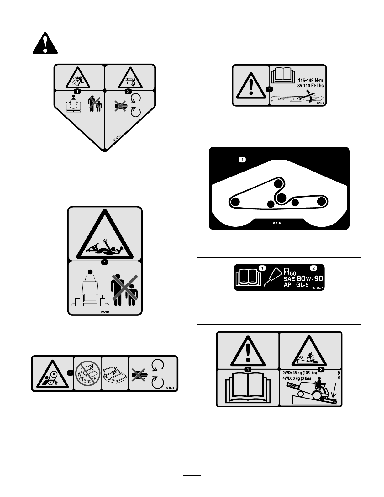
SafetyandInstructionalDecals
Safetydecalsandinstructionsareeasilyvisibletotheoperatorandarelocatednearanyareaofpotential
danger.Replaceanydecalthatisdamagedorlost.
106-6753
1.Thrownobjecthazard—keepbystandersasafedistance
fromthemachine.
2.Cutting/dismembermenthazardofhandorfoot,mower
blade—stayawayfrommovingparts.
93-7818
1.Warning—readtheOperator'sManualforinstructionson
torquingthebladebolt/nutto115-149N-m(85-110ft-lb).
107-2915
1.Entanglementhazard,shaft-keepbystandersasafe
distancefromthemachine.
100-6578
1.Entanglementhazard,belt—donotoperatethemachine
withtheshieldsorguardsremoved;alwayskeeptheshields
andguardsinplace;stayawayfrommovingparts.
85-6120
1.Beltrouting
93-6697
1.ReadtheOperator's
Manual.
2.AddSAE80w-90(API
GL-5)oilevery50hours.
105-7844
1.Warning—readtheOperator'sManual.
2.Rearwheelweightisrequiredwhenoperatingatwo–wheel
driveGroundsmaster328-DorGoundsmaster345.
6
Page 7
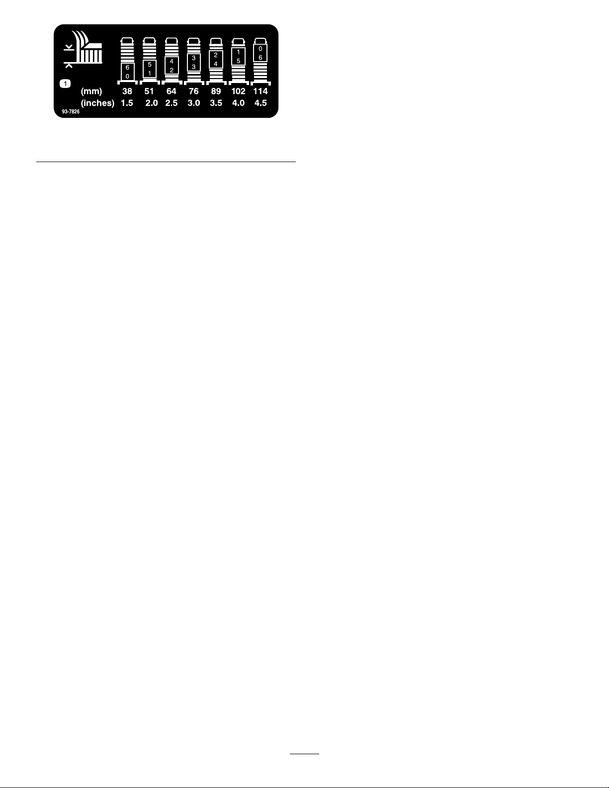
1.Height-of-cutadjustment
93-7826
7
Page 8
Setup
LooseParts
Usethechartbelowtoverifythatallpartshavebeenshipped.
ProcedureDescription
1
2
3
4
5
6
7
8
MediaandAdditionalParts
Largecastorwheelassembly2
Smallcastorwheelassembly
Driveshaft
Nopartsrequired
Nopartsrequired
Bolt,5/16x1-3/4inches
Locknut,5/16inches
Rollpin,3/16x1-1/2inches
Nopartsrequired
Nopartsrequired
Nopartsrequired
Qty.
Use
2
1
–
–
2
2
2
–
–
–
Installthecastorwheelassemblies.
Installthedriveshafttothetractionunit
Connecttheright-handpusharmtothe
cuttingunit
Connecttheleft-handpusharmtothe
cuttingunit
Connectthedriveshafttothecutting
unitgearbox
Installtheliftchains
Greasethemachine.
Installrearweight
Description
PartsCatalog
Operator'sManual
Note:Determinetheleftandrightsidesofthemachine
fromthenormaloperatingposition.
1
InstallingtheCastorWheel Assemblies
Partsneededforthisprocedure:
2Largecastorwheelassembly
2
Smallcastorwheelassembly
Procedure
Qty.
Use
1
1
Reviewthematerialandsaveinanappropriateplace:
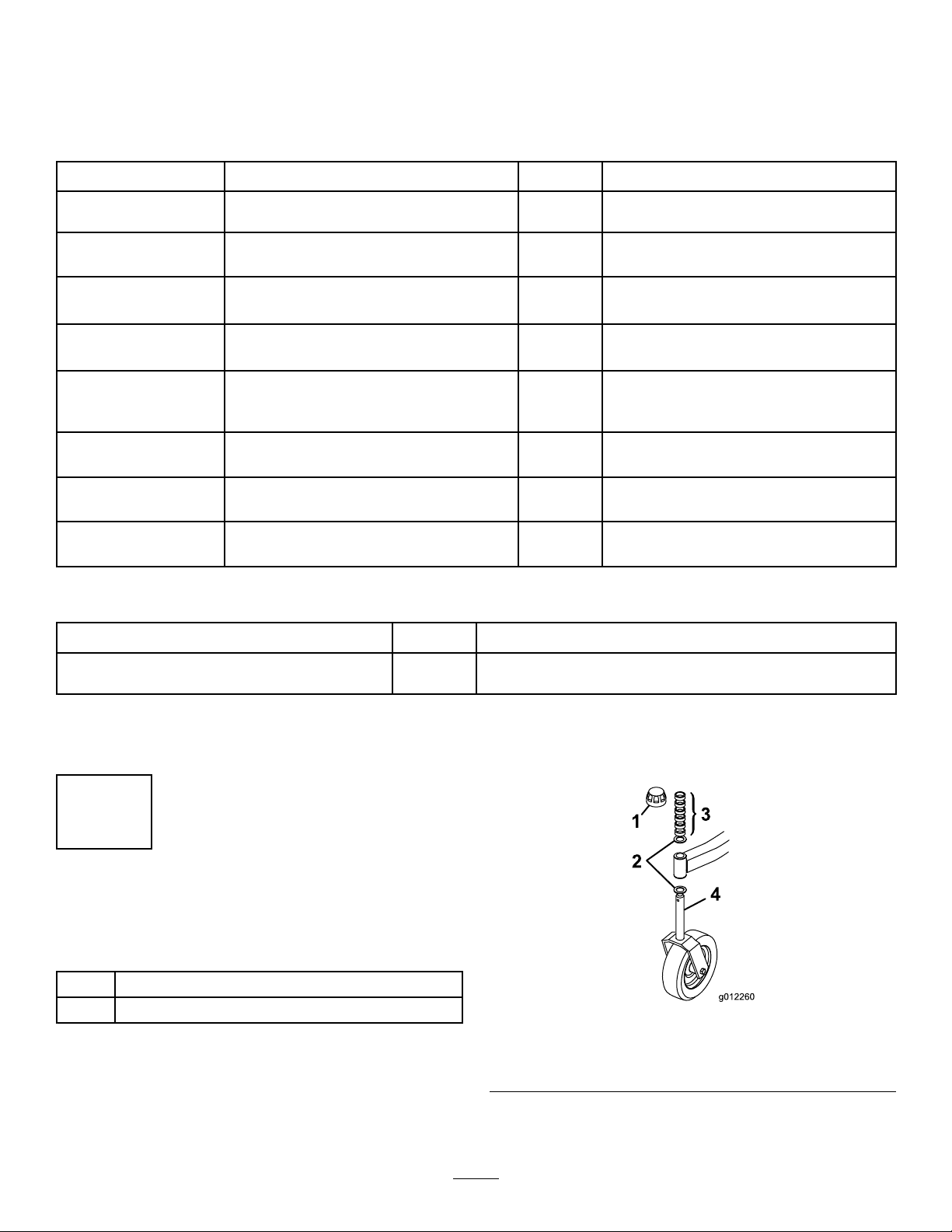
1.Removethetensioningcapsfromthespindleshafts
andslideoffthespacersandthrustwashers(Figure
&Figure3).
2
Figure2
1.Tensioningcap
2.Thrustwashers
3.Spacers
4.Large(front)castorspindle
Thethrustwashers,spacers,andtensioningcapshavebeen
installedonthecastorwheelspindlesforshipping.
2.Slidethespacersontothecastorspindletogetthe
desiredheight-of-cut;refertotheHeight-of-CutChart
8
Page 9

intheAdjustingtheHeightofcutsection.Slidea
thrustwasherontothespindle.Pushthelargecastor
spindlethroughthefrontcastorarmandthesmall
castorspindlethroughtherearcastorarm.Install
anotherthrustwasherandtheremainingspacersonto
thespindleandinstallthetensioningcaptosecurethe
assembly(Figure2&Figure3).
Important:Thethrustwashers,notthespacers,
mustcontactthetopandbottomofthecastorarm.
Figure3
1.Tensioningcap
2.Thrustwashers
3.Spacers
4.Small(rear)castorspindle
Figure4
1.Driveshaft
3
ConnectingtheRight-Hand PushArmtotheCuttingUnit
NoPartsRequired
3.Ensurethatallfourcastorwheelsaresetatthesame
height-of-cut;thenrollthecuttingunitoffofthe
woodenpallet.
2
InstallingtheDriveShafttothe TractionUnit
Partsneededforthisprocedure:
1
Driveshaft
Procedure
Slidethesmalleryokeendofthedriveshaftontothetraction
unitPTOshaftwhilealigningthemountingholes(Figure
4).Securethemwitharollpin.Donotinstallthefrontend
ofthedriveshaftatthistime.
Procedure
WARNING
Theright-handpusharmisspringloadedtoabout
45kg(100lb.).Suddenreleaseofthepusharm
couldcauseinjury.
Anotherpersonisneededtopushthearmdown
duringthisprocedure.
1.Removethe2self-tappingscrewssecuringthePTO
shieldtothetopofthecuttingunitgearboxmounting
plateandremovetheshield(Figure5).
Figure5
1.PTOshield
9
Page 10
2.Movethecuttingunitintopositioninfrontofthe
tractionunit.
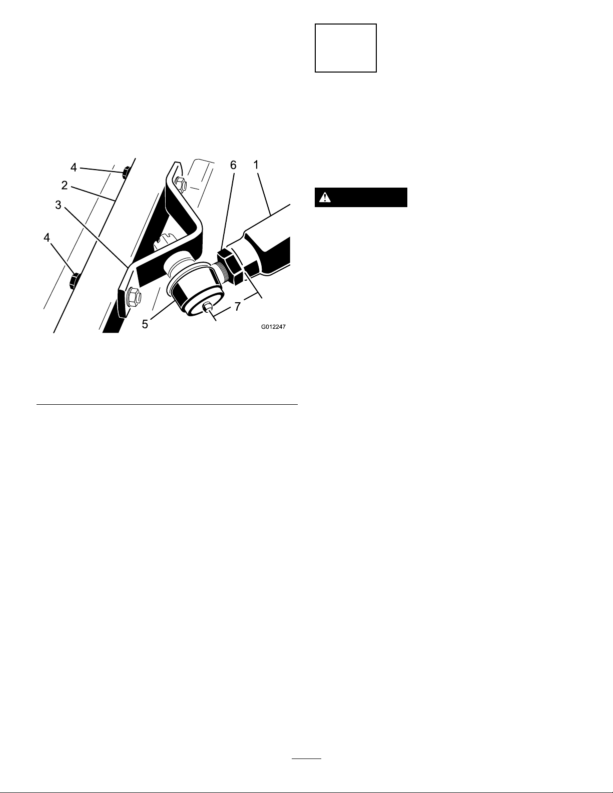
3.Measurethedistancefromtheendoftheright-hand
pusharmtothecenteroftheballjoint(greasetting)
(Figure6).Thedistanceshouldbe70mm(2-3/4
inches).Ifthedistanceisnot70mm(2-3/4inches),
loosenthejamnutsecuringtheballjointtothepush
armandrotatetheballjointinoroutuntilthecorrect
distanceisattained(Figure6).Donottightenthejam
nutatthistime.
Figure6
1.Right-handpusharm
2.Castorarm
3.Balljointmount6.Jamnut
4.Haveanotherpersoncarefullypushdownonthepush
armuntiltheholesintheballjointmountlineupwith
theholesinthecastorarm.Immediatelyslidea4x4
inchblockofwoodbetweenthetopofthepusharm
andtheundersideofthechassis.
5.Securetheballjointmounttothecastorarmwith2
capscrews(7/16x3inches),atwashers(7/16inches),
andangenuts(7/16inches).Positiontheatwashers
totheoutsideofthecastorarm.
4.Capscrewsandwashers
5.Balljoint
4
ConnectingtheLeft-Hand PushArmtotheCuttingUnit
NoPartsRequired
Procedure
WARNING
Theleft-handpusharmisspringloadedtoabout68
kg(150lb.).Suddenreleaseofthepusharmcould
causeinjury.
Anotherpersonisneededtopushthearmdown
duringthisprocedure.
1.Removethe2capscrews,atwashers,andangenuts
securingtheleft-handballjointmountandchain
brackettotheleft-handcastorarm(Figure7).Remove
theballjointmountandchainbracket.
2.Removethecotterpinandcastlenutsecuringthe
left-handballjointmounttotheleft-handpusharmon
thetractionunit.Installtheballjointmount(removed
fromthecastorarm)tothepusharmwiththecastle
nutandcotterpinpreviouslyremoved(Figure7).
3.Measurethedistancefromtheendoftheleft-hand
pusharmtothecenteroftheballjoint(greasetting)
(Figure7).Thedistanceshouldbe64mm(2-1/2
inches).Ifthedistanceisnot64mm(2-1/2inches),
loosenthejamnutsecuringtheballjointtothepush
armandrotatetheballjointinoroutuntilthedistance
isattained(Figure7).Donottightenthejamnutat
thistime.
6.Tightenthelargejamnutsecuringtheballjointtothe
pusharm(Figure6).Whentighteningthejamnut,hold
theballjointstraighttopermitproperoscillationduring
raisingandloweringofthecuttingunit.Carefully
removethewoodblockholdingthepusharmdown.
10
Page 11
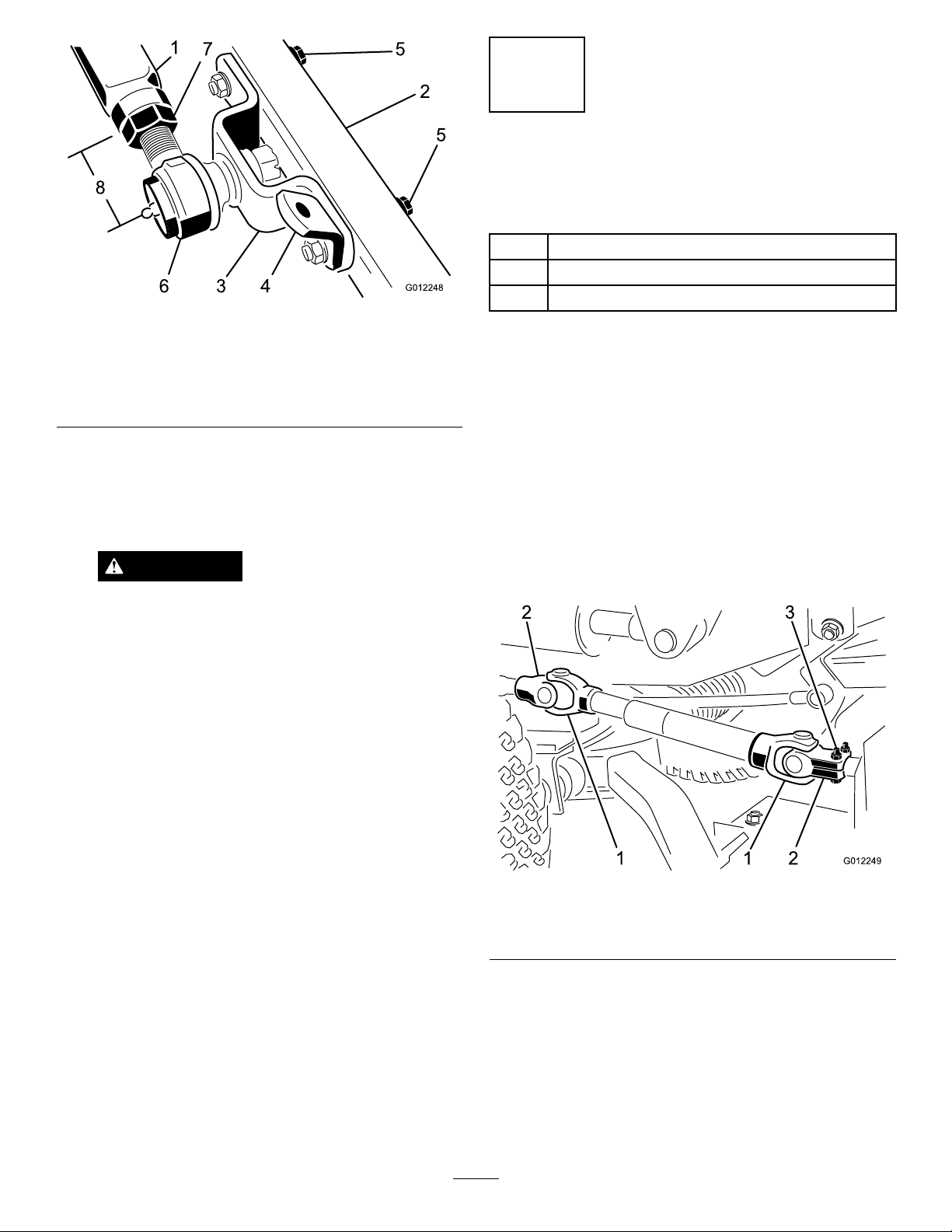
Figure7
1.Left-handpusharm5.Capscrewsandwashers
2.Castorarm
3.Balljointmount7.Jamnut
4.Chainmount
4.Haveanotherpersoncarefullypushdownonthepush
armuntiltheholesintheballjointmountlineupwith
theholesinthecastorarm.Immediatelyslidea4x4
inchblockofwoodbetweenthetopofthepusharm
andtheundersideofthechassis.
6.Balljoint
WARNING
Suddenreleaseofthepusharmcouldcause
injury.
5
ConnectingtheDriveShaftto theCuttingUnitGearBox
Partsneededforthisprocedure:
2
Bolt,5/16x1-3/4inches
2
Locknut,5/16inches
2
Rollpin,3/16x1-1/2inches
Procedure
Important:Thedriveshaftyokesmustbeexactlyin
linewitheachotherwhentheouteryokeisinstalledon
thegearboxsplinedPTOshaft.Removethesleeveand
changetheyokepositionifthealignmentisnotcorrect.
Misalignmentofthetwoyokeswillshortenthelifeof
thedriveshaftandcauseunnecessaryvibrationwhen
thecuttingunitisoperated.
1.Lineuptheholesintheyokeandinputshaftofthe
gearbox.Slidetheyokeontotheshaftandsecurethem
togetherwitharollpinand2capscrews(5/16x1-3/4
inches)andlocknuts(5/16inch)(Figure8).
Makesurethatthewoodenblockdoesnot
slipout.
5.Securetheballjointmountandchainbrackettothe
castorarmwiththecapscrews,atwashers,andange
nutspreviouslyremoved.Positiontheatwashersto
theoutsideofthecastorarm.Mountthechainbracket
intheforwardsetofholes.
6.Tightenthelargejamnutsecuringtheballjointtothe
pusharm.Whentighteningthejamnut,holdtheball
jointstraighttopermitproperoscillationduringraising
andloweringofthecuttingunit.Carefullyremovethe
woodblockholdingthepusharmdown.
Figure8
1.Driveshaftyokes
2.Yokesinphase
2.MountthePTOshieldtothetopofthecuttingunit
gearboxmountingplatewiththe2self-tappingscrews
previouslyremoved.
3.Rollpinandcapscrews
11
Page 12
6
8
InstallingtheLiftChains
NoPartsRequired
Procedure
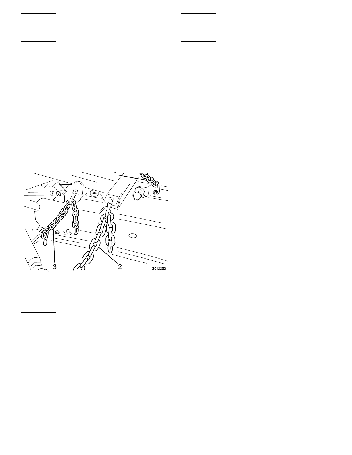
1.Connecttheliftchainstotheliftarmandcuttingunit
chainbracketswith6shackles,shacklepins(3/8x
1-1/2inches),andcotterpins(1/8x3/4inch)(Figure
9).Toensurethatthecuttingunitliftsproperly,secure
thechainstothefollowinglinkswhenconnecting:
•Frontchains-9thlink
•Rearchain-5thlink
2.Checktheoperationtoensurethatthechainsliftthe
decktightagainstthestopswhentheliftarmisraised.
InstallingRearWeight
NoPartsRequired
Procedure
TwoWheelDriveGroundsmaster300SeriesTractionUnits
complywiththeANSIB71.4-2004andEN836Standards
whenequippedwithrearweight.RefertochartinTraction
UnitOperator'sManualtodeterminethecombinationsof
weightrequired.OrderpartsfromyourlocalAuthorized
ToroDistributor.
FourWheelDriveGroundsmaster300SeriesTractionUnits
donotneedadditionalrearweighttocomplywiththeANSI
B71.4-2004andEN836Standards.
Figure9
1.Frontleftliftchain3.Rearliftchain
2.Frontrightliftchain
7
GreasingtheMachine
NoPartsRequired
Procedure
Beforeoperatingthemachine,itmustbegreasedtoensure
properlubricatingcharacteristics;refertoGreasingthe
BearingsandBushings.Failuretoproperlygreasethemachine
willresultinprematurefailureofcriticalparts.
12
Page 13
ProductOverview
Operation
Specications
Note:Specicationsanddesignaresubjecttochange
withoutnotice.
Widthof
Cut
Height
ofCut
Net
Weight
Attachments/Accessories
AselectionofToroapprovedattachmentsandaccessoriesis
availableforusewiththemachinetoenhanceandexpand
itscapabilities.ContactyourAuthorizedServiceDealeror
Distributororgotowww .T oro.comforalistofallapproved
attachmentsandaccessories.
1.829m(72inches)
Adjustablefrom38to1 14mm(1–1/2to4–1/2inches)
in1/2inch(13mm)increments
275kg(607lb.)
Note:Determinetheleftandrightsidesofthemachine
fromthenormaloperatingposition.
CAUTION
Ifyouleavethekeyintheignitionswitch,someone
couldaccidentlystarttheengineandseriously
injureyouorotherbystanders.
Removethekeyfromtheignitionbeforeyoudoany
maintenance.
CheckingtheLubricantinthe GearBox
ServiceInterval:Every50hours
ThegearboxindesignedtooperateonSAE80–90wt.gear
lube.Althoughthegearboxisshippedwithlubricantfrom
thefactory,checkthelevelbeforeoperatingthecuttingunit.
1.Positionthemachineandcuttingunitonalevelsurface.
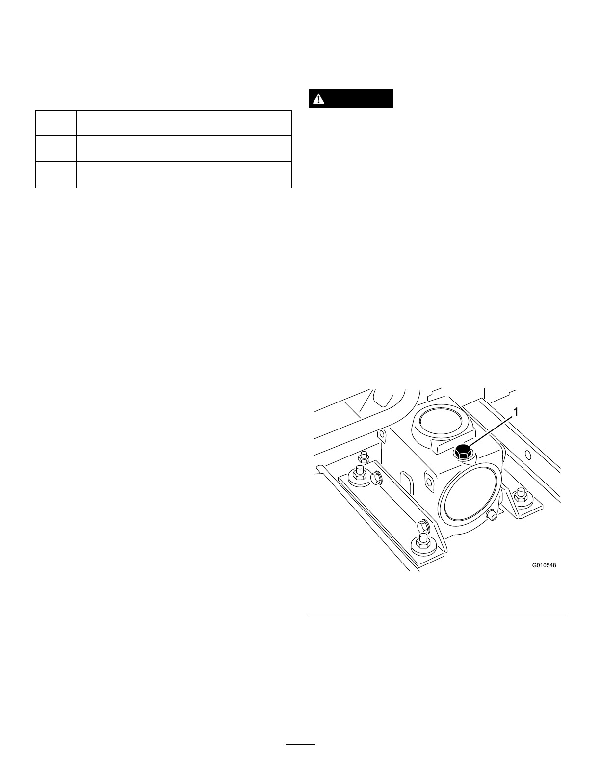
2.Removethedipstick/llplugfromthetopofthegear
Figure10)andmakesurethatthelubricantis
box(
betweenthemarksonthedipstick.Ifthelubricant
levelislow,addenoughlubricantuntilthelevelis
betweenthemarks.
Figure10
1.Dipstick/llplug
AdjustingtheHeight-of-Cut
Theheightofcutisadjustablefrom38to114mm(1-1/2
to4-1/2inches)in1/2inch(13mm)increments,byadding
orremovinganequalnumberofspacersfromthefrontand
rearcastorforks.Theheight-of-cutchartbelowgivesthe
combinationsofspacerstouseforallheight-of-cutsettings.
13
Page 14
Setting
38mm(1–1/2
inches)
50mm(2inches)
63mm(2–1/2
inches)
76mm(3inches)
89mm(3–1/2
inches)
102mm(4inches)
114mm(4–1/2
inches)
SpacersBelowCastorArm Height-of-Cut
FrontRear
00
11
22
33
44
55
66
Starttheengineandraisethecuttingunitsothatthe
height-of-cutcanbechanged.Stoptheengineafterthe
cuttingunitisraised.
25mm(1inch)height-of-cutcanbeattainedbymodifying
thecastorforksasfollows:
1.Removethefrontandrearcastorforksfromthecutting
deckandremovethewheelsfromtheforks.
2.Drilloutthe0.438inchdiameterholes(Figure11&
Figure12)ineachsideofthecastorforksto0.50inch
or0.516inchdiameter.
3.Usingthenewholes,installthecastorwheelsonthe
forksandinstalltheforksonthedeck.
Note:Theheight-of-cutdecalwillnowbeoffby
13mm(1/2inch)forspacerplacementandthe
height-of-cutwillbe25to102mm(1to4inches).
FrontCastorWheels
1.Removethetensioningcapfromthespindleshaftand
slidethespindleoutofthefrontcastorarm.Remove
thewasherfromthespindleshaft.Slidethespacers
ontothespindleshafttogetdesiredtheheight-of-cut,
thenslidethewasherontotheshaft(Figure11).
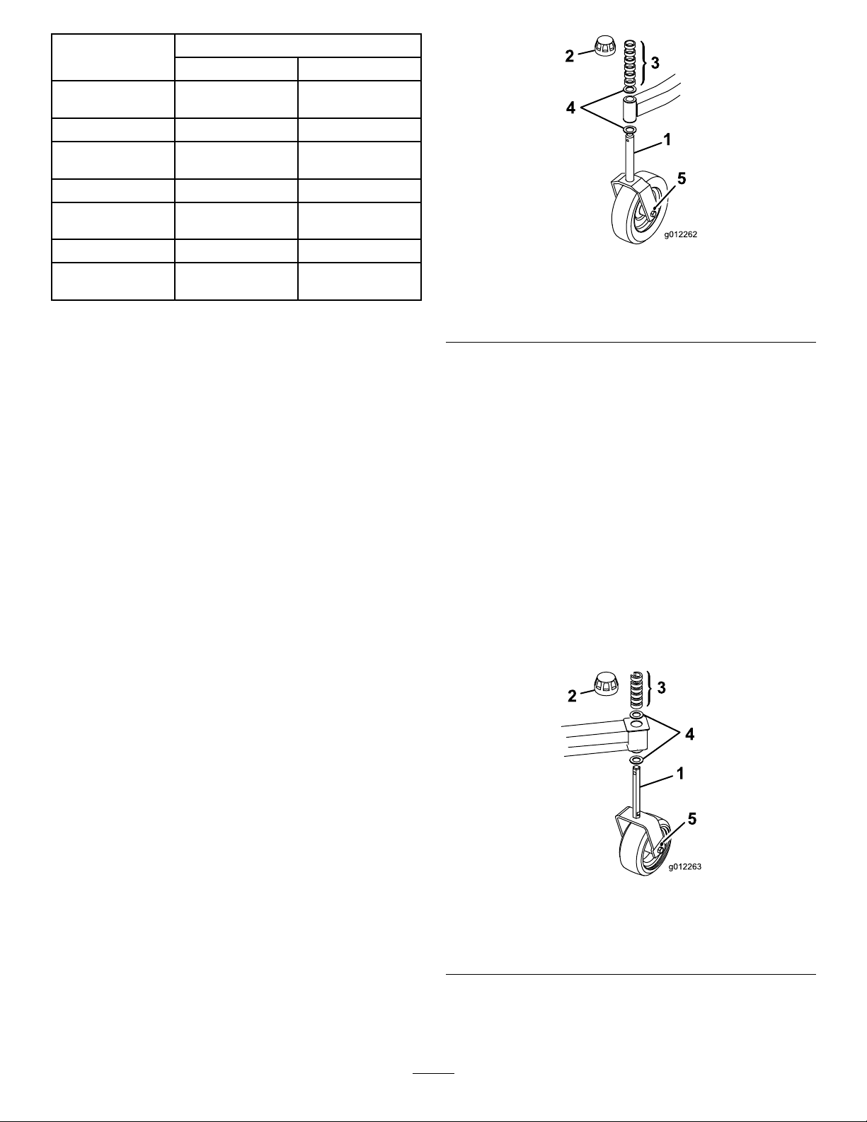
Figure11
1.Frontcastorwheel4.Thrustwashers
2.Tensioningcap5.0.438inchdiameterhole
3.Spacers
RearCastorWheels
1.Removethetensioningcapfromthespindleshaft
(Figure12).
Note:Therearcastorforkassemblydoesnotneed
toberemovedfromthecastorarmtochangethe
height-of-cut.
2.RemoveoraddtheC-shapedspacersatthenarrow
portionofthespindleshaft,belowthecastorarm,to
getthedesiredheight-of-cut(Figure12).Makesure
thatthethrustwashers-notthespacers-contactthetop
andbottomofthecastorarm.
3.Installthetensioningcaptosecuretheassembly
(Figure12).
4.Ensurethatallfourcastorwheelsaresetatthesame
height-of-cut.
2.Pushthecastorspindlethroughthefrontcastorarm,
installtheotherthrustwasherandremainingspacers
ontothespindle,andinstallthetensioningcapto
securetheassembly(Figure11).
Figure12
1.Rearcastorwheel4.Thrustwashers
2.Tensioningcap5.0.438diameterhole
3.Spacers
14
Page 15
AdjustingtheRollers
1
Note:Ifthecuttingunitistobeusedinthe25or38mm(1
or1-1/2inches)height-of-cutsetting,thecuttingunitrollers
mustberepositionedinthetopbracketholes.
1.Removethecotterpinssecuringtherollershaftsto
theundersideofthedeck.
2.Slidetheshaftsoutofthelowerbracketholes,alignthe
rollerswiththetopholes,andinstalltheshafts.
MowWhenGrassisDry
Moweitherinthelatemorningtoavoidthedew ,whichcauses
grassclumping,orinlateafternoontoavoidthedamage
thatcanbecausedbydirectsunlightonthesensitive,freshly
mowedgrass.
SelecttheProperHeight-of-CutSetting
toSuitConditions
3.Installthecotterpinstosecuretheassemblies.
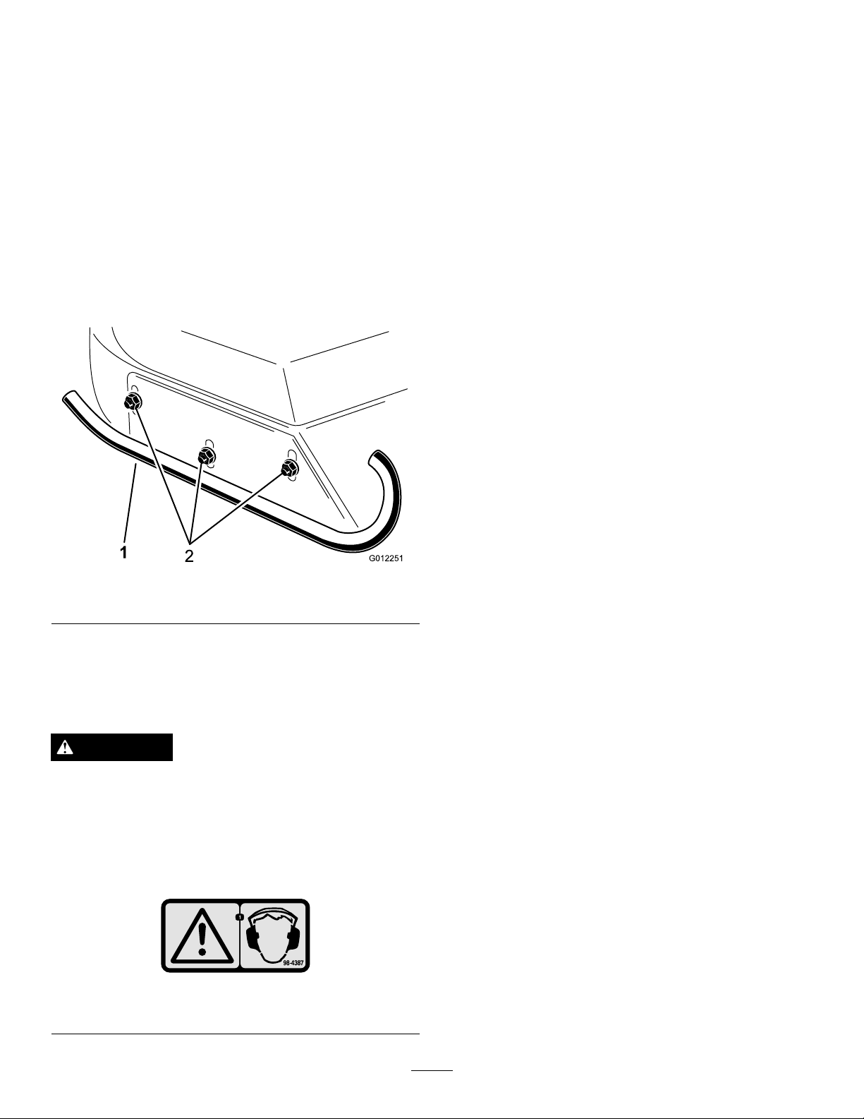
AdjustingtheSkids
Adjusttheskidsbylooseningtheangenuts,positioningthe
skidsasdesired,andtighteningtheangenuts(Figure13).
Figure13
1.Skid
2.Flangenuts
Removeapproximately26mm(1inch)ornomorethan1/3
ofthegrassbladewhencutting.Inexceptionallylushand
densegrassyoumayhavetoraisetheheight-of-cutsetting
anothernotch.Whencuttingin25or38mm(1or1-1/2
inches)height-of-cut,addasecondwasherbetweentherear
castorforksandthebottomofthecastorarmhousingsto
increasethebladerake.
MowinginExtremeConditions
Airisrequiredtocutandrecutgrassclippingsinthemower
housing,sodonotsettheheight-of-cuttoolowortotally
surroundthehousingbyuncutgrass.Alwaystrytohaveone
sideofthemowerhousingfreefromuncutgrass,allowingair
tobedrawnintothehousing.Whenmakinganinitialcut
throughthecenterofanuncutarea,operatethemachine
slowerandbackupifthemowerstartstoclog.
AlwaysMowwithSharpBlades
Asharpbladecutscleanlyandwithouttearingorshredding
thegrassbladeslikeadullblade.Tearingandshredding
causesthegrasstoturnbrownattheedgeswhichimpairs
growthandincreasessusceptibilitytodiseases.Makesurethat
thebladeisingoodconditionandafullsailispresent.
OperatingTips
Theuseofprotectiveequipment,suchasbutnotlimitedto,
foreyes,ears,feet,andheadisrecommended.
CAUTION
Thismachineproducessoundlevelsinexcessof
85dBAattheoperator'searandcancausehearing
lossthroughextendedperiodsofexposure.Wear
hearingprotectionwhenoperatingthismachine.
Wearhearingprotectionwhenoperatingthis
machine.
Figure14
1.Warning—wearhearingprotection.
ChecktheConditionoftheDeck
Makesurethatthecuttingchambersareingoodcondition.
Straightenanybendsinthechambercomponentstoensure
correctbladetip/chamberclearance.
Stopping
Ifthemachinehastobestoppedwhilecutting,aclumpof
grassclippingsmaybedepositedonthelawn.Followthis
procedureforstoppingwhilecutting
1.Withthedeckengaged,moveontoapreviouslycut
area.
2.Shifttoneutral,movethethrottlecontrollevertothe
Slowposition,androtatetheignitionkeytoOff.
AfterOperating
Toensureoptimumperformance,cleantheundersideofthe
mowerhousingaftereachuse.Ifresidueisallowedtobuild
upinthemowerhousing,cuttingperformancewilldecrease.
15
Page 16
Maintenance
RecommendedMaintenanceSchedule(s)
MaintenanceService
Interval
Aftertherst2hours
Aftertherst10hours
Beforeeachuseordaily
Every50hours
Every400hours
MaintenanceProcedure
•Tightenthecastorwheelnuts
•Tightenthecastorwheelnuts
•T orquethebladebolts
•Lubricatethegreasettings
•Checktheblades
•Checkthegearboxlubricant
•Checkthebladedrivebeltadjustment
•Cleanunderthecuttingunitbeltcovers
•Tightenthecastorwheelnuts
•T orquethebladebolts
•Changethegearboxlubricant
CAUTION
Ifyouleavethekeyintheignitionswitch,someonecouldaccidentallystarttheengineandseriously
injureyouorotherbystanders.
Removethekeyfromtheignitionswitchbeforeyoudoanymaintenance.
PreMaintenance
Important:Thefastenersonthecoversofthismachine
aredesignedtoremainonthecoverafterremoval.
Loosenallofthefastenersoneachcoverafewturnsso
thatthecoverisloosebutstillattached,thengoback
andloosenthemuntilthecovercomesfree.Thiswill
preventyoufromaccidentallystrippingtheboltsfree
oftheretainers.
Lubrication
ServiceInterval:Beforeeachuseordaily
Themachinehasgreasettingsthatmustbelubricated
regularlywithNo.2GeneralPurposeLithiumBaseGrease.
Ifthemachineisoperatedundernormalconditions,lubricate
allbearingsandbushingsdailyorimmediatelyafterevery
washing.
Lubricatethefollowingareas:
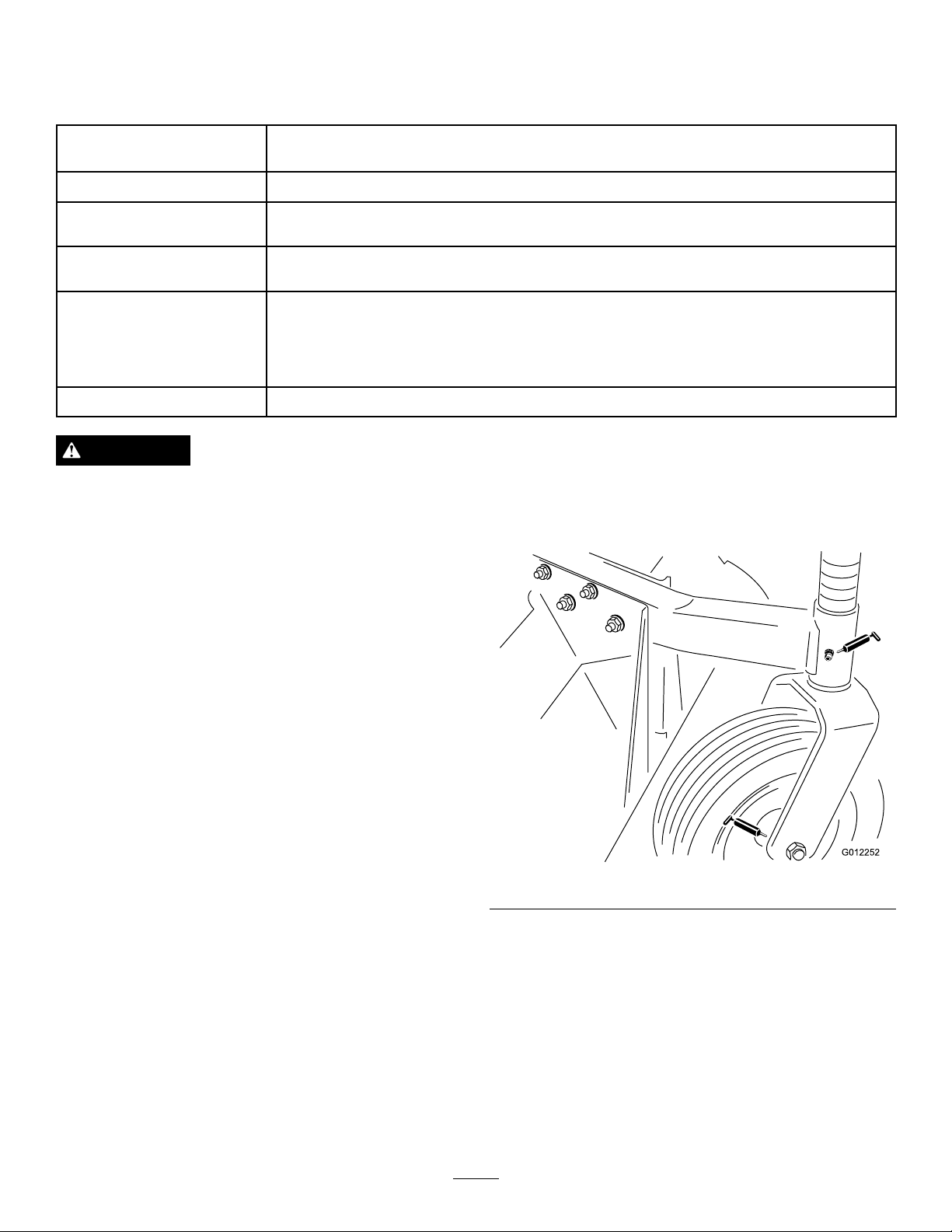
•Frontcastorspindlebushings(
•Castorwheelbearings(Figure15)&Figure16)
•Bladespindlebearings(Figure17)
•Idlerarmpivot(Figure17)
•Rightandleftpusharmballjoints(
Figure15)
Figure17)
Figure15
Alsoremovetherearcastorspindleshaftfromthecastor
armandcoatthehexshaftwithNo.2generalpurpose
lithiumbasegreaseormolybdenumbasegreaseevery
50hours(
Figure16).
16
Page 17
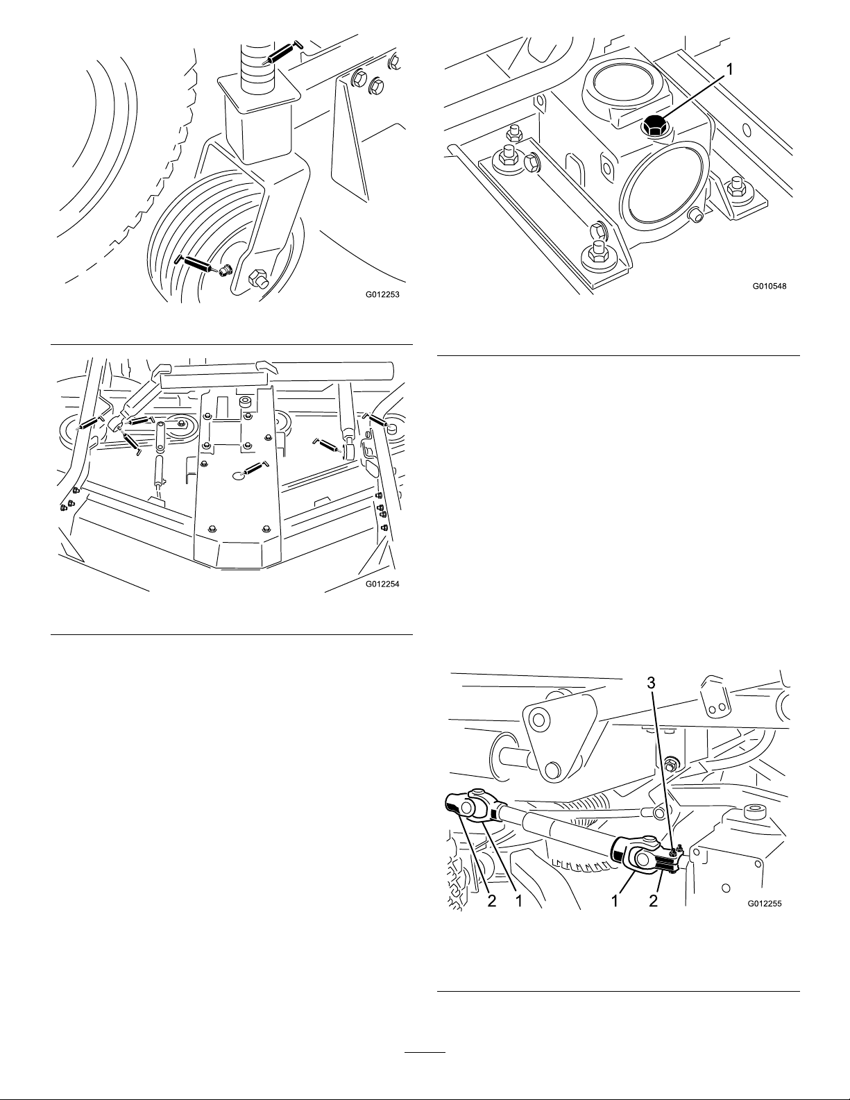
Figure16
Figure17
Positionthemachineandcuttingunitonalevelsurface
andlowerthecuttingunit.Removethedipstick/llplug
fromthetopofthegearbox(
thatthelubricantisbetweenthemarksonthedipstick.
Ifthelubricantlevelislow ,addSAE80-90wt.gearlube
untilthelevelisbetweenthemarks
Figure18)andmakesure
Figure18
1.Dipstick/llplug
SeparatingtheCuttingUnit fromtheTractionUnit
1.Positionthemachineonlevelsurface,lowerthecutting
unittotheoor,shuttheengineoffandengagethe
parkingbrake.
2.Removetheself-tappingscrewssecuringtheshieldto
thetopofthecuttingunitandsettheshieldaside.
3.Driveouttherollpinsecuringthedriveshaftyoketo
theinputshaftofthegearbox(
capscrewsandlocknutsandslidetheyokeoffofthe
inputshaft.Ifthetractionunitwillbeusedwithout
thecuttingunit,drivetherollpinoutoftheyokeat
tractionunitPTOshaftandremovetheentiredrive
shaftfromthetractionunit.
Figure19).Loosenthe
17
1.Driveshaftyokes
2.Yokesinphase
Figure19
3.Rollpinandcapscrews
Page 18
DANGER
IftheengineisstartedandthePTOshaftis
allowedtorotate,seriousinjurycouldresult.
DonotstarttheengineandengagethePTO
leverwhenthePTOshaftisnotconnectedto
thegearboxonthecuttingunit.
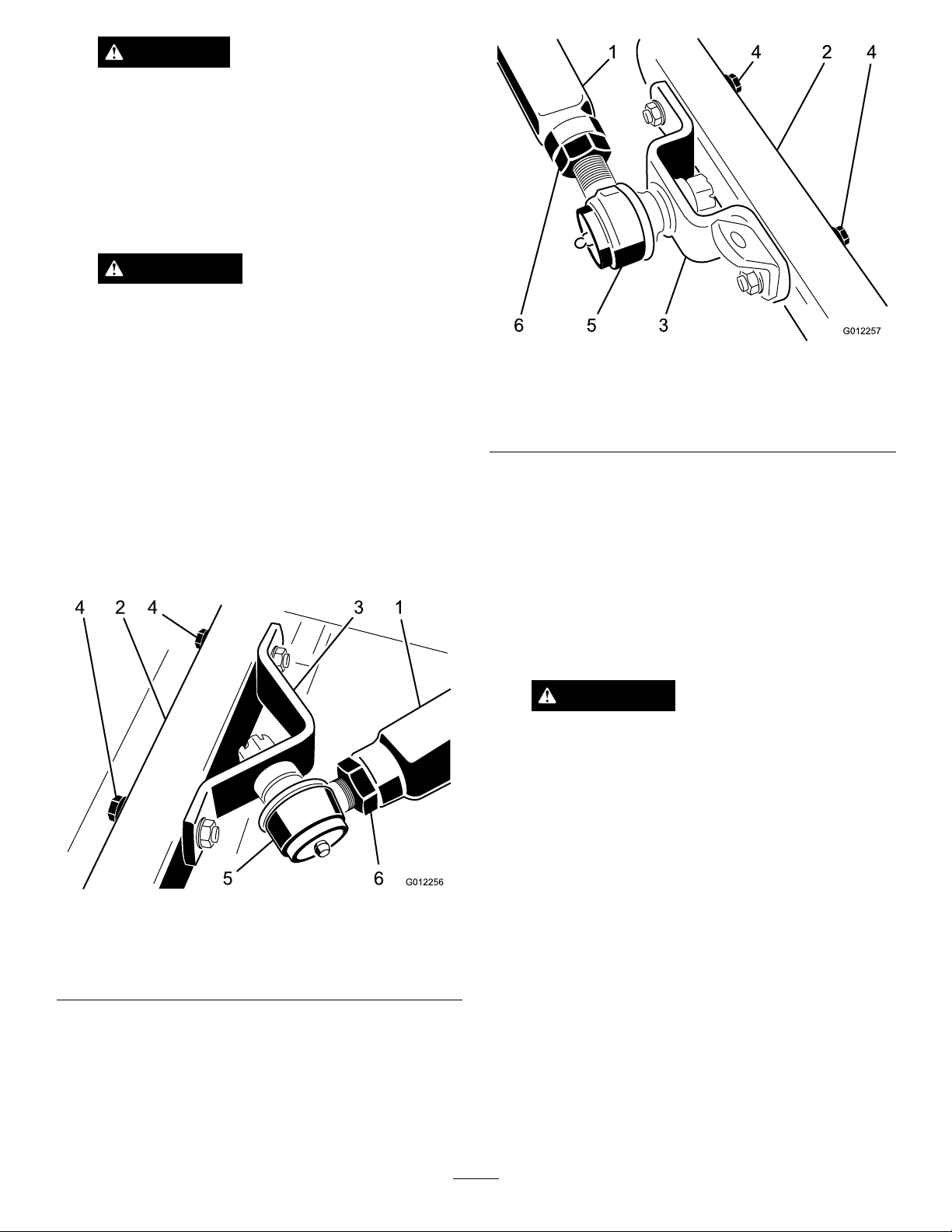
4.Disconnectthecotterpinsandclevispinssecuringthe
liftchainstotheliftarms.
WARNING
Theright-handpusharmisspringloadedto
about45kg(100lb.)andtheleft-handpush
armisspringloadedtoabout68kg(150lb.).
Suddenreleaseofthepusharmcouldcause
injury.
Anotherpersonisneededtopushthearm
downduringthisprocedure.
Figure21
1.Leftt-handpusharm4.Capscrewsandwashers
2.Castorarm
3.Balljointmount6.Jamnut
5.Balljoint
5.Haveanotherpersonpushdownontherightpush
armwhileyouremovethecapscrews,atwashers,and
locknutssecuringtheballjointmounttothecastor
armonthecuttingunit(Figure20).Nowthehelper
cancarefullyallowthepusharmtomoveupward,
whichwillgraduallyreleasethe45kg(100pounds)of
springload.
Figure20
1.Right-handpusharm
2.Castorarm
3.Balljointmount6.Jamnut
6.Haveanotherpersonpushdownontheleftpush
armwhileyouremovethecapscrews,atwashers,
andlocknutssecuringtheballjointmountandchain
brackettothecastorarmonthecuttingunit(Figure
21
).Nowthehelpercancarefullyallowthepusharm
tomoveupward,whichwillgraduallyreleasethe68kg
(150pounds)ofspringload
4.Capscrewsandwashers
5.Balljoint
7.Rollthecuttingunitawayfromthetractionunit.
MountingtheCuttingUnitto theTractionUnit
1.Positionthemachineonalevelsurfaceandshutthe
engineoff.
2.Movethecuttingunitintopositioninfrontofthe
tractionunit.
WARNING
Theright-handpusharmisspringloadedto
about45kg(100lb.)andtheleft-handpush
armisspringloadedtoabout68kg(150lb.).
Suddenreleaseofthepusharmcouldcause
injury.
Anotherpersonisneededtopushthearm
downduringthisprocedure.
3.Haveanotherpersoncarefullypushdownontheright
pusharmuntiltheholesintheballjointmountlineup
withtheholesinthecastorarm(Figure20).
4.Securetheballjointmounttothecastorarmwiththe
capscrews,atwashers,andangenuts.Positionthe
atwasherstotheoutsideofthecastorarm.
5.Haveanotherpersoncarefullypushdownonthe
leftpusharmuntiltheholesintheballjointmount
lineupwiththeholesinthecastorarm(
Immediatelyslidea4x4inchblockofwoodbetween
thetopofthepusharmandtheundersideofthe
chassis.
Figure21).
18
Page 19
WARNING
Suddenreleaseofthepusharmcouldcause
injury.
Makesurethatthewoodenblockdoesnot
slipout.
6.Securetheballjointmountandchainbrackettothe
castorarmwiththecapscrews,atwashers,andange
nuts.Positiontheatwasherstotheoutsideofthe
castorarm.Mountthechainbracketintheforward
setofholes.
7.Carefullyremovethewoodblockholdingthepush
armdown.
8.Lineuptheholesintheyokeandinputshaftofthe
gearbox.Slidetheyokeontotheshaftandsecurethem
togetherwitharollpin,2capscrews(5/16x1-3/4
inches),and2locknuts(5/16inches).
ReplacingtheDriveBelt
Thebladedrivebelt,tensionedbythespringloadedidler
pulley,isverydurable.However,aftermanyhoursofuse,
thebeltwillshowsignsofwear.Signsofawornbeltare:
squealingwhenbeltisrotating,bladesslippingwhencutting
grass,frayededges,burnmarksandcracks.Replacethebeltif
anyoftheseconditionsareevident.
1.Lowerthecuttingunittotheshopoor.Removethe
beltcoversfromthetopofthecuttingunitandsetthe
coversaside.
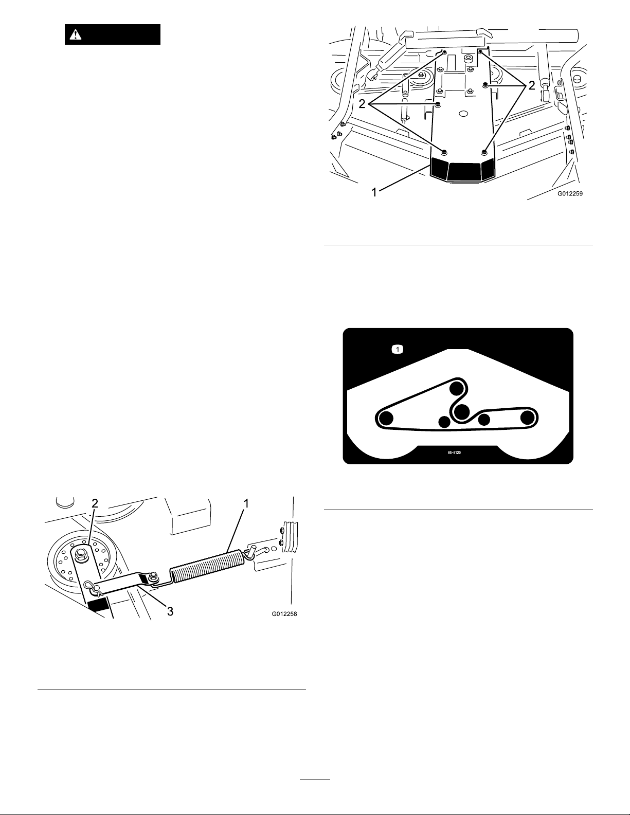
2.Unhookthespringfromtheidlerarmbracketto
releasethebelttension(
pinandclevispinsecuringtheidlerarmbrackettothe
idlerarm.
Figure22).Removethecotter
Figure23
1.Gearboxplate2.Capscrewsandnuts
4.Removetheoldbeltfromaroundthespindlepulleys
andthroughtheidlerpulleyassembly.
5.Routethenewbeltaroundthespindlepulleysand
throughtheidlerpulleyassemblyasshowninFigure
24.
Figure24
1.Beltrouting
Figure22
1.Spring
2.Idlerarm
3.Idlerarmbracket
3.Removethecapscrewsandnutssecuringthegearbox
platetothedeckchannels(
boxplateandgearboxoffofthedeckchannelsand
layitontopofthedeck.
Figure23).Liftthegear
6.Repositionthegearboxplateonthedeckchannels
whileroutingthebeltaroundthegearboxpulley.
Mountthegearboxplatetothedeckchannelswiththe
capscrewsandnutspreviouslyremoved.
7.Installtheidlerarmbrackettotheidlerarmwiththe
cotterpinandclevispin(Figure22).Hookthespring
ontotheidlerarmbracket.Toensurethatthereis
propertensiononthedrivebelt,thespringshouldbe
extendedtoalengthofapproximately7inches(18cm).
Ifthespringisnotextendedtothislength,relocatethe
springrodtoanewmountingholefurtherawayfrom
thebelt.
8.Installthebeltcovers.
19
Page 20
ServicingtheFrontBushings intheCastorArms
Thecastorarmshavebushingspressedintothetopand
bottomofthetubeandaftermanyhoursofoperation,the
bushingswillwear.Tocheckthebushings,movethecastor
forkbackandforthandfromsidetoside.Ifthecastor
spindleislooseinsidethebushings,thebushingsareworn
andmustbereplaced.
1.Raisethecuttingunitsothatthewheelsareoffof
theoor.Blockthecuttingunitsothatitcannot
accidentallyfall.
2.Removethetensioningcap,spacer(s),andthrust
washerfromthetopofthecastorspindle.
3.Pullthecastorspindleoutofthemountingtube.
Allowthethrustwasherandspacer(s)toremainon
thebottomofthespindle.
4.Insertapinpunchintothetoporbottomofthe
mountingtubeanddrivethebushingoutofthetube
(
Figure25).Alsodrivetheotherbushingoutofthe
tube.Cleantheinsideofthetubestoremovedirt.
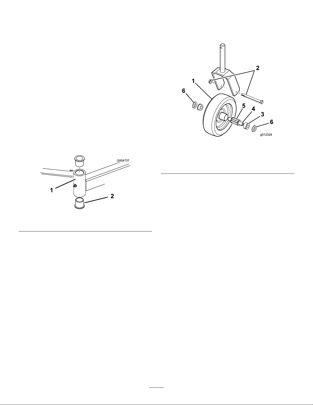
26).Graspthecastorwheelandslidethecapscrewout
ofthefork.
2.Pullthespannerbushingoutofthewheelhub(Figure
26).
Figure26
1.Castorwheel4.Spannerbushing
2.Capscrewandlocknut
3.Bushing(2)6.Washer(2)
5.Rollerbearing
Figure25
1.Castorarmtube
5.Applygreasetotheinsideandoutsideofthenew
bushings.Usingahammerandatplate,drivethe
bushingsintothemountingtube.
6.Inspectthecastorspindleforwearandreplaceitif
damaged.
7.Pushthecastorspindlethroughthebushingsand
mountingtube.Slidethethrustwasherandspacer(s)
ontothespindle.Installthetensioningcaponthe
castorspindletoretainallpartsinplace.
2.Bushings
ServicingtheCastorWheels andBearings
Thecastorwheelrotatesonahigh-qualityrollerbearingand
issupportedbyaspannerbushing.Evenaftermanyhours
ofuse,providedthatthebearingwaskeptwelllubricated,
thebearingwearwillbeminimal.However,failuretokeep
thebearinglubricatedwillcauserapidwear.Awobblycastor
wheelusuallyindicatesawornbearing.
1.Removethelocknutfromthecapscrewholdingthe
castorwheelassemblybetweenthecastorfork(Figure
3.Removethebushingfromthewheelhubandallowthe
bearingtofallout(Figure26).Removethebushing
fromtheoppositesideofthewheelhub.
4.Checkthebearing,spanner,andinsideofthewheel
hubforwear.Replacedamagedparts.
5.Toassemblethecastorwheel,pushthebushinginto
thewheelhub.Slidethebearingintothewheelhub.
Pushtheotherbushingintotheopenendofthewheel
hubtocaptivatethebearinginsidethewheelhub.
6.Carefullyslidethespannerthroughthebushingsand
thewheelhub(Figure26).
7.Installthecastorwheelassemblybetweenthecastor
forkandsecureitinplacewiththecapscrew,washers,
andlocknut.
8.Lubricatethecastorwheelbearingthroughthegrease
tting,usingNo.2generalpurposelithiumbasegrease.
RemovingandInstallingthe Blade(s)
Theblademustbereplacedifasolidobjectishit,the
bladeisout-of-balance,worn,orbent.Alwaysusegenuine
Tororeplacementbladestoensuresafetyandoptimum
performance.Neverusebladesmadebyothermanufacturers
becausetheycouldbedangerous.
1.Raisethecuttingunittothehighestposition,engage
theparkingbrake,stoptheengine,andremovethe
ignitionkey.Blockthecuttingunittopreventitfrom
accidentallyfalling.
20
Page 21
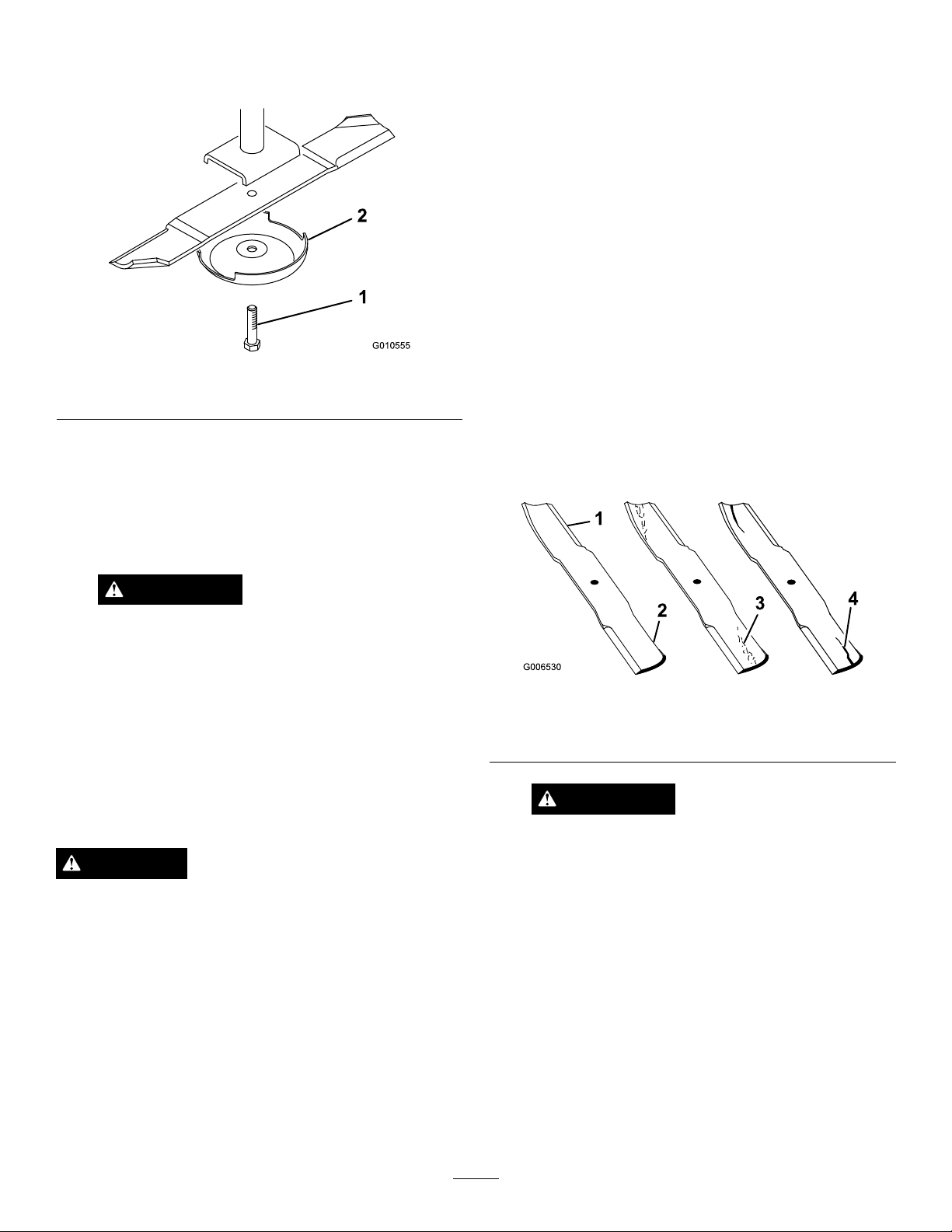
2.Grasptheendofthebladeusingaragorthickly
G010555
1
2
paddedglove.Removethebladebolt,anti-scalpcup,
andbladefromthespindleshaft(Figure27).
Figure27
1.Bladebolt2.Anti-scalpcup
3.Installtheblade-sailfacingtowardthecuttingunit-with
theanti-scalpcupandbladebolt.Tightentheblade
boltto85-110ft-lb(115-149N-m).
Twoareasmustbeconsideredwhencheckingandservicing
thecuttingblade:thesailandthecuttingedge.Bothcutting
edgesandthesail,whichistheturnedupportionopposite
thecuttingedge,contributetoagoodquality-of-cut.The
sailisimportantbecauseitpullsgrassupstraight,thereby
producinganevencut.However,thesailwillgraduallywear
downduringoperation,andthisconditionisnormal.Asthe
sailwearsdown,thequality-of-cutwilldegradesomewhat,
althoughthecuttingedgesaresharp.Thecuttingedgeof
theblademustbesharpsothatthegrassiscutratherthan
torn.Adullcuttingedgeisevidentwhenthetipsofthegrass
appearbrownandshredded.Sharpenthecuttingedgesto
correctthiscondition.
1.Raisethecuttingunittothehighestposition,shutthe
engineoff,andengagetheparkingbrake.Blockthe
cuttingunittopreventitfromaccidentallyfalling.
2.Examinethecuttingendsofthebladecarefully,
especiallywheretheatandcurvedpartsoftheblade
meet(Figure28).Sincesandandabrasivematerialcan
wearawaythemetalthatconnectstheatandcurved
partsoftheblade,checkthebladebeforeusingthe
machine.Ifwearisnoticed(Figure28),replacethe
blade;refertoRemovingtheCuttingBlade.
Important:Thecurvedpartoftheblademustbe
pointingtowardtheinsideofthecuttingunitto
ensurepropercutting.
WARNING
Donottrytostraightenabladethatisbent,
andneverweldabrokenorcrackedblade.
Alwaysuseanewbladetoensurecontinued
safetycerticationoftheproduct.
InspectingandSharpeningthe Blade(s)
ServiceInterval:Beforeeachuseordaily
Every50hours
DANGER
Awornordamagedbladecanbreak,andapiece
ofthebladecouldbethrownintotheoperator's
orbystander'sarea,resultinginseriouspersonal
injuryordeath.
•Inspectthebladeperiodicallyforwearor
damage.
•Donottrytostraightenabladethatisbent.
•Neverweldabrokenorcrackedblade.
Figure28
1.Cuttingedge3.Wear/slotforming
2.Curvedarea/sail4.Crack
WARNING
Ifthebladeisallowedtowear,aslotwillform
betweenthesailandatpartoftheblade
(Figure28).Eventually,apieceoftheblade
maybreakoffandbethrownfromunderthe
housing,possiblyresultinginseriousinjuryto
yourselforbystanders.
•Inspectthebladeperiodicallyforwearor
damage.
•Replaceawornordamagedbladewitha
newT orobladetoensurecontinuedsafety
certicationoftheproduct.
•Replaceawornordamagedbladewitha
newTorobladetoensurecontinuedsafety
certicationoftheproduct.
3.Examinethecuttingedgesofallblades.Sharpenthe
cuttingedgesiftheyaredullornicked.Sharpenonly
thetopsideofthecuttingedgeandmaintainthe
21
Page 22
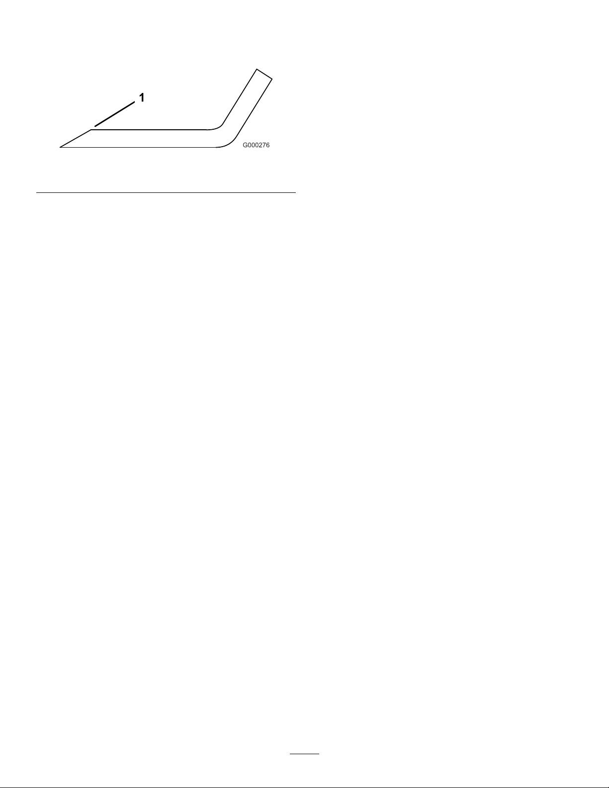
originalcuttingangletoensuresharpness(Figure29).
Thebladewillremainbalancedifthesameamountof
metalisremovedfrombothcuttingedges.
betweenthespindlehousingandthebottomofthe
cuttingunit.
7.Removethebolts,atwashers,lockwashers,andnuts
fromtheouterspindleintheareawheretheshims
mustbeadded.Toraiseorlowertheblade,addashim,
PartNo.3256-24,betweenthespindlehousingand
thebottomofthecuttingunit.Continuetocheckthe
alignmentofthebladesandaddshimsuntilthetipsof
thebladesarewithintherequireddimension.
Figure29
1.Sharpenatoriginalangle
4.Tocheckthebladeforbeingstraightandparallel,lay
thebladeonalevelsurfaceandchecktheends.The
endsoftheblademustbeslightlylowerthanthecenter,
andthecuttingedgemustbelowerthantheheelofthe
blade.Thisbladewillproduceagoodqualityofcutand
requireminimalpowerfromtheengine.Bycontrasta
bladethatishigherattheendsthanthecenter,orifthe
cuttingedgeishigherthantheheel,thebladeisbentor
warpedandmustbereplaced.
5.Installtheblade(s).
CheckingandCorrecting MismatchofBlades
Ifthereismismatchbetweentheblades,thegrasswillappear
streakedwhenitiscut.Thisproblemcanbecorrectedby
makingsurethatthebladesarestraightandalloftheblades
arecuttingonthesameplane.
Important:Donotusemorethanthreeshimsat
anyoneholelocation.Usedecreasingnumbersof
shimsinadjacentholesifmorethanoneshimis
addedtoanyoneholelocation.
8.Hookthespringontotheidlerarmbracket.
9.Installthebeltcovers.
1.Usinga1meter(3foot)longcarpenterslevel,nda
levelsurfaceontheshopoor.
2.Raisetheheight-of-cuttothehighestposition;referto
AdjustingtheHeight-of-Cut.
3.Lowerthecuttingunitontotheatsurface.Remove
thecoversfromthetopofthecuttingunit.
4.Unhookthespringfromtheidlerarmbracketto
releasethebelttension.
5.Rotatethebladesuntiltheendsfaceforwardand
backward.Measurefromtheoortothefronttipof
thecuttingedge.Rememberthisdimension.Then
rotatethesamebladesothattheoppositeendis
forward,andmeasureagain.Thedifferencebetween
thedimensionsmustnotexceed3mm(1/8inch).If
thedimensionexceeds3mm(1/8inch),replacethe
bladebecauseitisbent.Makesuretomeasureallof
theblades.
6.Comparethemeasurementsoftheouterbladeswith
thecenterblade.Thecenterblademustnotbemore
than10mm(3/8inch)lowerthantheouterblades.If
thecenterbladeismorethan10mm(3/8inch)lower
thantheouterblades,proceedtostep
7andaddshims
22
Page 23

Troubleshooting
Problem
Thecuttingunitwillnotcutorcutspoorly.
PossibleCauseCorrectiveAction
1.Thebladesaredull.
2.Oneormorebladesarebentor
damaged.
3.Thespindleboltsareloose.3.Torquethespindleboltsto115to149
4.Thecuttingunitbeltsarelooseor
broken.
5.Thegearboxpulleyisloose.5.Tightenorreplacethepulley .
6.Agearboxshaftisbroken.6.Replaceanybrokenshafts.
7.ThePTObeltisbroken.7.ReplacethePTObelt.
8.ThePTOpulleyislooseorbroken.
9.ThePTOshaftisbroken.9.ReplacethePTOshaft.
10.Thepulleyontheengineoutputshaft
islooseorbroken.
1.Sharpentheblades.
2.Replacetheblades.
N-m(85to110ft-lb).
4.Tightenorreplacethebeltsas
necessary.
8.Tightenorreplacethepulley.
10.Tightenorreplacethepulley .
23
Page 24

Notes:
24
Page 25

Notes:
25
Page 26

Notes:
26
Page 27

DeclarationofIncorporation
TheT oroCompany,8111LyndaleAve.South,Bloomington,MN,USAdeclaresthatthefollowingunit(s)
conform(s)tothedirectiveslisted,wheninstalledinaccordancewiththeaccompanyinginstructionsontocertain
ToromodelsasindicatedontherelevantDeclarationsofConformity.
ModelNo.
30716314000001andUp
SerialNo.
ProductDescriptionInvoiceDescription
72inGuardianRecycler
Mower
GM300RECYCLERDECK
GeneralDescription
72inGuardianRecycler
Directive
Mower
2006/42/EC,
2000/14/EC
RelevanttechnicaldocumentationhasbeencompiledasrequiredperPartBofAnnexVIIof2006/42/EC.
Wewillundertaketotransmit,inresponsetorequestsbynationalauthorities,relevantinformationonthispartly
completedmachinery.Themethodoftransmissionshallbeelectronictransmittal.
ThismachineryshallnotbeputintoserviceuntilincorporatedintoapprovedToromodelsasindicatedonthe
associatedDeclarationofConformityandinaccordancewithallinstructions,wherebyitcanbedeclaredin
conformitywithallrelevantDirectives.
Certied:EUTechnicalContact:
PeterT etteroo
ToroEuropeNV
B-2260Oevel-Westerloo
Belgium
DavidKlisTel.003214562960
Sr.EngineeringManager
811 1LyndaleAve.South
Bloomington,MN55420,USA
September26,2013
Fax003214581911
27
Page 28

TheToroTotalCoverageGuarantee
ALimitedWarranty
ConditionsandProductsCovered
TheToroCompanyanditsafliate,T oroWarrantyCompany,pursuant
toanagreementbetweenthem,jointlywarrantyourToroCommercial
product(“Product”)tobefreefromdefectsinmaterialsorworkmanship
fortwoyearsor1500operationalhours*,whicheveroccursrst.This
warrantyisapplicabletoallproductswiththeexceptionofAerators
(refertoseparatewarrantystatementsfortheseproducts).Wherea
warrantableconditionexists,wewillrepairtheProductatnocosttoyou
includingdiagnostics,labor,parts,andtransportation.Thiswarranty
beginsonthedatetheProductisdeliveredtotheoriginalretailpurchaser.
*Productequippedwithanhourmeter.
InstructionsforObtainingWarrantyService
YouareresponsiblefornotifyingtheCommercialProductsDistributoror
AuthorizedCommercialProductsDealerfromwhomyoupurchasedthe
Productassoonasyoubelieveawarrantableconditionexists.Ifyouneed
helplocatingaCommercialProductsDistributororAuthorizedDealer,or
ifyouhavequestionsregardingyourwarrantyrightsorresponsibilities,
youmaycontactusat:
ToroCommercialProductsServiceDepartment
ToroWarrantyCompany
811 1LyndaleAvenueSouth
Bloomington,MN55420-1196
952–888–8801or800–952–2740
E-mail:[email protected]
OwnerResponsibilities
AstheProductowner,youareresponsibleforrequiredmaintenance
andadjustmentsstatedinyourOperator'sManual.Failuretoperform
requiredmaintenanceandadjustmentscanbegroundsfordisallowinga
warrantyclaim.
ItemsandConditionsNotCovered
Notallproductfailuresormalfunctionsthatoccurduringthewarranty
periodaredefectsinmaterialsorworkmanship.Thiswarrantydoesnot
coverthefollowing:
•Productfailureswhichresultfromtheuseofnon-Tororeplacement
parts,orfrominstallationanduseofadd-on,ormodiednon-T oro
brandedaccessoriesandproducts.Aseparatewarrantymaybe
providedbythemanufactureroftheseitems.
•Productfailureswhichresultfromfailuretoperformrecommended
maintenanceand/oradjustments.Failuretoproperlymaintainyour
ToroproductpertheRecommendedMaintenancelistedinthe
Operator’sManualcanresultinclaimsforwarrantybeingdenied.
•ProductfailureswhichresultfromoperatingtheProductinan
abusive,negligent,orrecklessmanner.
•Partssubjecttoconsumptionthroughuseunlessfoundtobe
defective.Examplesofpartswhichareconsumed,orusedup,
duringnormalProductoperationinclude,butarenotlimitedto,brake
padsandlinings,clutchlinings,blades,reels,rollersandbearings
(sealedorgreasable),bedknives,sparkplugs,castorwheelsand
bearings,tires,lters,belts,andcertainsprayercomponentssuchas
diaphragms,nozzles,andcheckvalves,etc.
•Failurescausedbyoutsideinuence.Conditionsconsideredtobe
outsideinuenceinclude,butarenotlimitedto,weather,storage
practices,contamination,useofunapprovedfuels,coolants,
lubricants,additives,fertilizers,water,orchemicals,etc.
•Failureorperformanceissuesduetotheuseoffuels(e.g.gasoline,
diesel,orbiodiesel)thatdonotconformtotheirrespectiveindustry
standards.
•Normalnoise,vibration,wearandtear,anddeterioration.
•Normal“wearandtear”includes,butisnotlimitedto,damageto
seatsduetowearorabrasion,wornpaintedsurfaces,scratched
decalsorwindows,etc.
Parts
Partsscheduledforreplacementasrequiredmaintenancearewarranted
fortheperiodoftimeuptothescheduledreplacementtimeforthatpart.
Partsreplacedunderthiswarrantyarecoveredforthedurationofthe
originalproductwarrantyandbecomethepropertyofT oro.Torowill
makethenaldecisionwhethertorepairanyexistingpartorassemblyor
replaceit.T oromayuseremanufacturedpartsforwarrantyrepairs.
DeepCycleandLithium-IonBatteryWarranty:
DeepcycleandLithium-Ionbatterieshaveaspeciedtotalnumberof
kilowatt-hourstheycandeliverduringtheirlifetime.Operating,recharging,
andmaintenancetechniquescanextendorreducetotalbatterylife.Asthe
batteriesinthisproductareconsumed,theamountofusefulworkbetween
chargingintervalswillslowlydecreaseuntilthebatteryiscompletelyworn
out.Replacementofwornoutbatteries,duetonormalconsumption,
istheresponsibilityoftheproductowner.Batteryreplacementmaybe
requiredduringthenormalproductwarrantyperiodatowner’sexpense.
Note:(Lithium-Ionbatteryonly):ALithium-Ionbatteryhasapartonly
proratedwarrantybeginningyear3throughyear5basedonthetime
inserviceandkilowatthoursused.RefertotheOperator'sManualfor
additionalinformation.
MaintenanceisatOwner’sExpense
Enginetune-up,lubrication,cleaningandpolishing,replacementoflters,
coolant,andcompletingrecommendedmaintenancearesomeofthe
normalservicesT oroproductsrequirethatareattheowner’sexpense.
GeneralConditions
RepairbyanAuthorizedT oroDistributororDealerisyoursoleremedy
underthiswarranty.
NeitherTheToroCompanynorT oroWarrantyCompanyisliablefor
indirect,incidentalorconsequentialdamagesinconnectionwiththe
useoftheToroProductscoveredbythiswarranty ,includingany
costorexpenseofprovidingsubstituteequipmentorserviceduring
reasonableperiodsofmalfunctionornon-usependingcompletion
ofrepairsunderthiswarranty.ExceptfortheEmissionswarranty
referencedbelow,ifapplicable,thereisnootherexpresswarranty .
Allimpliedwarrantiesofmerchantabilityandtnessforuseare
limitedtothedurationofthisexpresswarranty .
Somestatesdonotallowexclusionsofincidentalorconsequential
damages,orlimitationsonhowlonganimpliedwarrantylasts,sothe
aboveexclusionsandlimitationsmaynotapplytoyou.Thiswarranty
givesyouspeciclegalrights,andyoumayalsohaveotherrightswhich
varyfromstatetostate.
Noteregardingenginewarranty:
TheEmissionsControlSystemonyourProductmaybecoveredby
aseparatewarrantymeetingrequirementsestablishedbytheU.S.
EnvironmentalProtectionAgency(EPA)and/ortheCaliforniaAir
ResourcesBoard(CARB).Thehourlimitationssetforthabovedonot
applytotheEmissionsControlSystemWarranty.RefertotheEngine
EmissionControlWarrantyStatementsuppliedwithyourproductor
containedintheenginemanufacturer’sdocumentationfordetails
CountriesOtherthantheUnitedStatesorCanada
CustomerswhohavepurchasedT oroproductsexportedfromtheUnitedStatesorCanadashouldcontacttheirT oroDistributor(Dealer)toobtain
guaranteepoliciesforyourcountry ,province,orstate.IfforanyreasonyouaredissatisedwithyourDistributor'sserviceorhavedifcultyobtaining
guaranteeinformation,contacttheT oroimporter.
374-0253RevB
 Loading...