

Page 1
FormNo.3383-165RevA
Groundsmaster
®
7210Traction
Unit
ModelNo.30381—SerialNo.314000001andUp
Registeratwww.T oro.com.
OriginalInstructions(EN)
*3383-165*A
Page 2
ThisproductcomplieswithallrelevantEuropeandirectives;
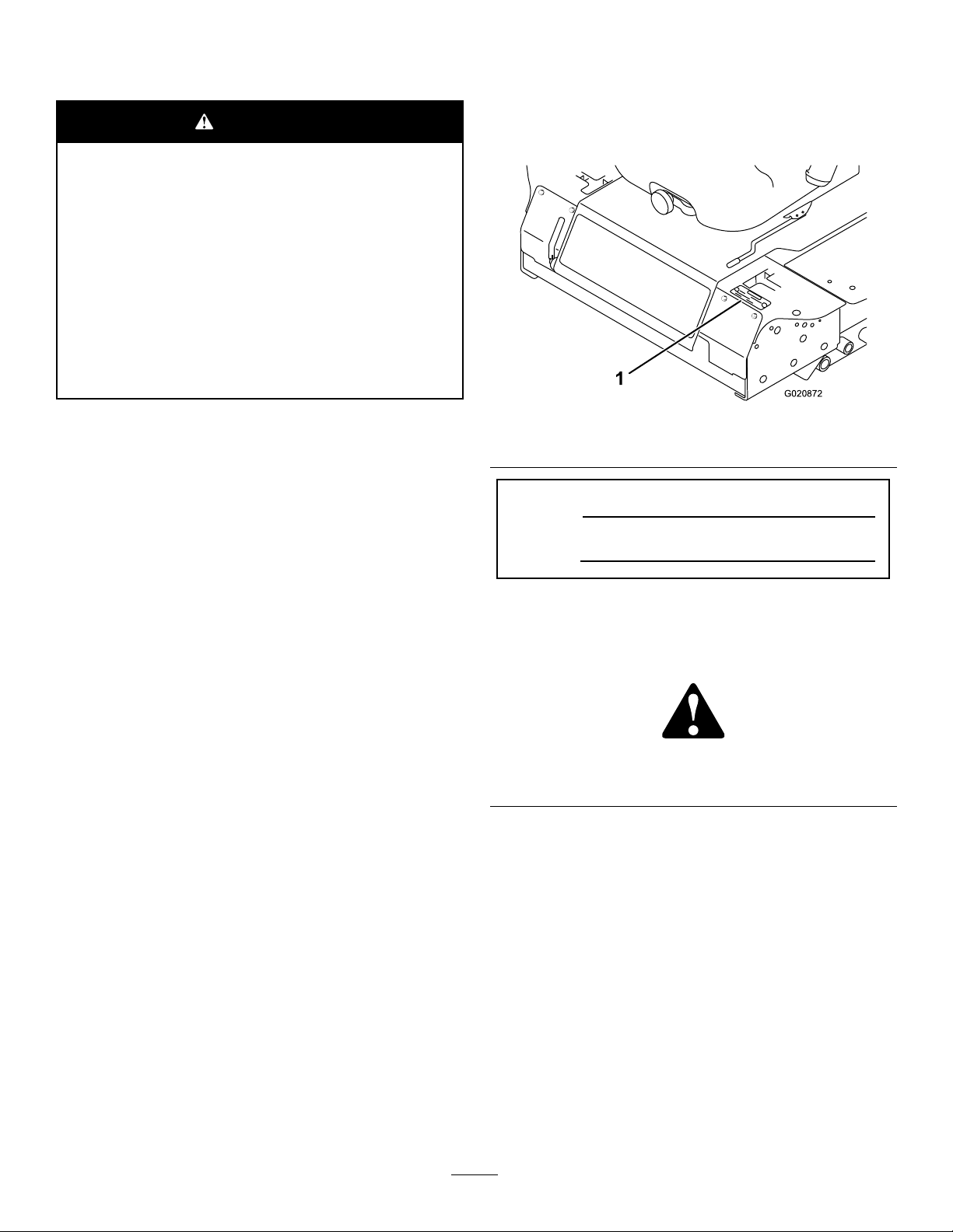
G020872
1
fordetails,pleaseseetheseparateproductspecicDeclaration
ofConformity(DOC)sheet.
WARNING
CALIFORNIA
Proposition65Warning
Thisproductcontainsachemicalorchemicals
knowntotheStateofCaliforniatocausecancer,
birthdefects,orreproductiveharm.
Dieselengineexhaustandsomeofits
constituentsareknowntotheStateof
Californiatocausecancer,birthdefects,
andotherreproductiveharm.
Wheneveryouneedservice,genuineT oroparts,oradditional
information,contactanAuthorizedServiceDealerorToro
CustomerServiceandhavethemodelandserialnumbersof
yourproductready.Figure1identiesthelocationofthe
modelandserialnumbersontheproduct.Writethenumbers
inthespaceprovided.
Becauseinsomeareastherearelocal,state,orfederal
regulationsrequiringthatasparkarresterbeusedonthe
engineofthismachine,asparkarresterisavailableas
anoption.Ifyourequireasparkarrester,contactyour
AuthorizedToroServiceDealer.
GenuineT orosparkarrestersareapprovedbytheUSDA
ForestryService.
Important:ItisaviolationofCaliforniaPublic
ResourceCodeSection4442touseoroperatetheengine
onanyforest-covered,brush-covered,orgrass-covered
landwithoutasparkarrestermufermaintainedin
workingorder,ortheengineconstricted,equipped,and
maintainedforthepreventionofre.Otherstatesor
federalareasmayhavesimilarlaws.
Introduction
Important:Usethismanualinconjunctionwiththe
operator’smanualsforthePolarTrackitoranyother
attachmentsforadditionalinformationonthesafe
operationandmaintenanceofyourmachineandthe
attachments.
Figure1
1.Modelandserialnumberlocation
ModelNo.
SerialNo.
Thismanualidentiespotentialhazardsandhassafety
messagesidentiedbythesafetyalertsymbol(Figure2),
whichsignalsahazardthatmaycauseseriousinjuryordeath
ifyoudonotfollowtherecommendedprecautions.
Figure2
1.Safetyalertsymbol
Thismanualalsouses2wordstohighlightinformation.
Importantcallsattentiontospecialmechanicalinformation
andNoteemphasizesgeneralinformationworthyofspecial
attention.
Thismachineisusedinthesummerwitharotary-blade
lawnmowerattachmentandinthewinterwithasnowremoval
attachmentandisintendedtobeusedbyprofessional,hired
operatorsincommercialapplications.
Readthisinformationcarefullytolearnhowtooperateand
maintainyourproductproperlyandtoavoidinjuryand
productdamage.Youareresponsibleforoperatingthe
productproperlyandsafely.
YoumaycontactTorodirectlyatwww .Toro.comforproduct
andaccessoryinformation,helpndingadealer,ortoregister
yourproduct.
©2014—TheToro®Company
8111LyndaleAvenueSouth
Bloomington,MN55420
Contactusatwww.Toro.com.
2
PrintedintheUSA
AllRightsReserved
Page 3

Contents
Introduction..................................................................2
Safety...........................................................................4
SafeOperatingPractices...........................................4
ToroRidingMowerSafety........................................5
SoundPowerLevel..................................................6
SoundPressureLevel...............................................6
VibrationLevel......................................................7
SlopeIndicator.......................................................8
SafetyandInstructionalDecals.................................9
Setup...........................................................................15
1AdjustingtheROPS.............................................15
2InstallingWeights(forCECompliance)...................16
3CheckingFluidLevels...........................................17
4ActivatingandChargingtheBattery........................17
5InstallingtheMowerDeck/PolarTrac.....................18
6ReadingtheManualsandViewingtheTraining
Materials............................................................26
ProductOverview.........................................................27
Controls...............................................................27
Specications........................................................28
Attachments/Accessories........................................28
Operation....................................................................29
AddingFuel...........................................................29
FillingtheFuelTank...............................................30
CheckingtheEngineOilLevel.................................30
CheckingtheCoolingSystem...................................30
CheckingtheHydraulicSystem................................30
UsingtheRolloverProtectionSystem(ROPS)............30
ThinkSafetyFirst...................................................31
OperatingtheParkingBrake....................................32
StartingandStoppingtheEngine..............................32
DrivingtheMachine...............................................33
StoppingtheMachine.............................................34
OperatingtheMower..............................................34
UsingtheSafetyInterlockSystem.............................35
PositioningtheSeat................................................38
UnlatchingtheSeat.................................................38
PushingtheMachinebyHand..................................39
LoadingMachines..................................................39
TransportingtheMachine........................................40
Maintenance.................................................................41
RecommendedMaintenanceSchedule(s)......................41
DailyMaintenanceChecklist....................................42
PremaintenanceProcedures........................................43
Lubrication...............................................................43
GreasingtheBearingsandBushings..........................43
ServicingtheMowerDeckGearBox
Lubricant...........................................................45
EngineMaintenance..................................................46
CheckingtheAirCleaner.........................................46
ServicingtheEngineOil..........................................47
FuelSystemMaintenance...........................................48
ServicingtheWaterSeparator..................................48
CleaningtheFuelTank............................................49
FuelLinesandConnections.....................................49
BleedingtheFuelSystem.........................................49
BleedingAirfromtheInjectors................................50
ElectricalSystemMaintenance....................................50
ServicingtheBattery...............................................50
StoringtheBattery..................................................51
CheckingtheFuses.................................................51
DriveSystemMaintenance.........................................52
CheckingtheTirePressure......................................52
ReplacingtheCasterWheelsandBearings..................52
CoolingSystemMaintenance......................................53
CheckingtheCoolingSystem..................................53
CleaningtheRadiator..............................................53
BrakeMaintenance....................................................54
AdjustingtheParkingBrakeInterlockSwitch..............54
BeltMaintenance......................................................55
CheckingtheAlternatorBelt...................................55
ReplacingtheBladeDriveBelts................................55
ControlsSystemMaintenance.....................................56
AdjustingtheControlLeverNeutralInterlock
Switch...............................................................56
AdjustingtheControlLeverNeutralReturn...............57
AdjustingtheTractionDriveforNeutral....................58
AdjustingtheMaximumGroundSpeed.....................59
AdjustingtheTracking............................................60
HydraulicSystemMaintenance....................................61
CheckingtheHydraulicSystem................................61
ChangingtheHydraulicOilAndFilter.......................62
Cleaning...................................................................62
CleaningUndertheMower......................................62
WasteDisposal.......................................................62
Storage........................................................................63
Machine................................................................63
Engine..................................................................63
3
Page 4

Safety
Improperlyusingormaintainingthemachinecanresult
ininjury.T oreducethepotentialforinjury,complywith
thesesafetyinstructionsandalwayspayattentiontothe
safetyalertsymbol,whichmeansCaution,Warning,or
Danger—personalsafetyinstruction.Failuretocomplywith
theinstructionmayresultinpersonalinjuryordeath.
•Thoroughlyinspecttheareawheretheequipmentisto
beusedandremoveallobjectswhichmaybethrownby
themachine.
•Replacefaultysilencers/mufers.
•Beforeusing,alwaysvisuallyinspecttoseethattheblades,
bladeboltsandcutterassemblyarenotwornordamaged.
Replacewornordamagedbladesandboltsinsetsto
preservebalance.
SafeOperatingPractices
ThefollowinginstructionsareadaptedfromtheCEN
standardEN836:1997andANSIB71.4-2012.
Thisproductiscapableofamputatinghandsandfeetand
throwingobjects.Alwaysfollowallsafetyinstructionsto
avoidseriousinjuryordeath.
Important:RefertotheROPSHardCab
Man ual
foradditionalcabsafetyinformation.
Training
•ReadtheOperator'sManualandothertrainingmaterial
carefully.Befamiliarwiththecontrols,safetysigns,and
theproperuseoftheequipment.
•Neverallowchildrenorpeopleunfamiliarwiththese
instructionstousethelawnmower.Localregulationscan
restricttheageoftheoperator.
•Nevermowwhilepeople,especiallychildren,orpetsare
nearby.
•Keepinmindthattheoperatororuserisresponsiblefor
accidentsorhazardsoccurringtootherpeopleortheir
property.
•Donotcarrypassengers.
•Alldriversshouldseekandobtainprofessionaland
practicalinstruction.Suchinstructionshouldemphasize:
–theneedforcareandconcentrationwhenworking
withride-onmachines;
–controlofaride-onmachineslidingonaslopewill
notberegainedbytheapplicationofthecontrol
levers.Themainreasonsforlossofcontrolare:
◊insufcientwheelgrip,especiallyonwetgrass;
◊beingdriventoofast;
◊inadequatebraking;
◊thetypeofmachineisunsuitableforitstask;
◊lackofawarenessoftheeffectofground
conditions,especiallyslopes;
◊incorrectloaddistribution.
Preparation
•Whileoperatingthemachine,alwayswearsubstantial
footwearandlongtrousers.Donotoperatethe
equipmentwhenbarefootorwearingopensandals.
Operator’ s
Operation
•Bealert,slowdownandusecautionwhenmakingturns.
Lookbehindandtothesidebeforechangingdirections.
•Donotoperatetheengineinaconnedspacewhere
dangerouscarbonmonoxidefumescancollect.
•Operateonlyindaylightoringoodarticiallight.
•Beforeattemptingtostarttheengine,disengageallblade
attachmentclutchesandshiftintoneutral.
•Rememberthereisnosuchthingasasafeslope.Travel
ongrassslopesrequiresparticularcare.T oguardagainst
overturning:
–donotstoporstartsuddenlywhenonaslope;
–useslowspeedsonslopesandduringtightturns;
–stayalertforhumpsandhollowsandotherhidden
hazards;
•Watchoutfortrafcwhencrossingornearroadways.
•Stopthebladesfromrotatingbeforecrossingsurfaces
otherthangrass.
•Whenusinganyattachments,neverdirectdischargeof
materialtowardbystandersnorallowanyonenearthe
machinewhileinoperation.
•Neveroperatethemachinewithdamagedguards,shields,
orwithoutsafetyprotectivedevicesinplace.
•Donotchangetheenginegovernorsettingsoroverspeed
theengine.Operatingtheengineatexcessivespeedmay
increasethehazardofpersonalinjury.
•Beforeleavingtheoperator'sposition:
–disengagethepowertake-offandlowerthe
attachments;
–changeintoneutralandsettheparkingbrake;
–stoptheengineandremovethekey.
•Disengagedrivetoattachments,stoptheengine,and
removetheignitionkey:
–beforeclearingblockagesoruncloggingchute;
–beforechecking,cleaningorworkingonthelawn
mower;
–afterstrikingaforeignobject.Inspectthelawn
mowerfordamageandmakerepairsbeforerestarting
andoperatingtheequipment;
–ifthemachinestartstovibrateabnormally(check
immediately).
•Donotoperatethemowerundertheinuenceofalcohol
ordrugs.
4
Page 5

•Lightningcancausesevereinjuryordeath.Iflightning
isseenorthunderisheardinthearea,donotoperate
themachine;seekshelter.
•Disengagedrivetoattachmentswhentransportingornot
inuse.
•Stoptheengineanddisengagedrivetoattachmentbefore
refuelling.
RolloverProtectionSystem
(ROPS)—UseandMaintenance
•TheROPSisanintegralandeffectivesafetydevice.Keep
afoldingROPSintheraisedandlockedpositionanduse
theseatbeltwhenoperatingthemachine.
•LowerafoldingROPStemporarilyonlywhenabsolutely
necessary.Donotweartheseatbeltwhenfoldeddown.
•Beawarethereisnorolloverprotectionwhenafolded
ROPSisinthedownposition.
•Becertainthattheseatbeltcanbereleasedquicklyin
theeventofanemergency.
•Checktheareatobemowedandneverfolddowna
foldingROPSinareaswherethereareslopes,dropoffs
orwater.
•Checkcarefullyforoverheadclearances(i.e.branches,
doorways,electricalwires)beforedrivingunderany
objectsanddonotcontactthem.
•KeeptheROPSinsafeoperatingconditionby
periodicallythoroughlyinspectingfordamageand
keepingallmountingfastenerstight.
•ReplaceadamagedROPS.Donotrepairorrevise.
•DonotremovetheROPS.
•AnyalterationstoaROPSmustbeapprovedbythe
manufacturer.
SafeHandlingofFuels
•Toavoidpersonalinjuryorpropertydamage,use
extremecareinhandlinggasoline.Gasolineisextremely
ammableandthevaporsareexplosive.
•Extinguishallcigarettes,cigars,pipes,andothersources
ofignition.
•Useonlyanapprovedfuelcontainer.
•Neverremovefuelcaporaddfuelwiththeengine
running.
•Allowenginetocoolbeforerefueling.
•Neverrefuelthemachineindoors.
•Neverstorethemachineorfuelcontainerwherethereis
anopename,spark,orpilotlightsuchasonawater
heateroronotherappliances.
•Neverllcontainersinsideavehicleoronatruckor
trailerbedwithaplasticliner.Alwaysplacecontainerson
thegroundawayfromyourvehiclebeforelling.
•Removeequipmentfromthetruckortrailerandrefuelit
ontheground.Ifthisisnotpossible,thenrefuelsuch
equipmentwithaportablecontainer,ratherthanfroma
fueldispensernozzle.
•Keepthenozzleincontactwiththerimofthefueltank
orcontaineropeningatalltimesuntilfuelingiscomplete.
•Donotuseanozzlelockopendevice.
•Iffuelisspilledonclothing,changeclothingimmediately.
•Neveroverllfueltank.Replacefuelcapandtighten
securely.
MaintenanceandStorage
•Keepallnuts,boltsandscrewstighttobesurethe
equipmentisinsafeworkingcondition.
•Neverstoretheequipmentwithfuelinthetankinsidea
buildingwherefumesmayreachanopenameorspark.
•Allowtheenginetocoolbeforestoringinanyenclosure.
•Toreducetherehazard,keeptheengine,
silencer/mufer,batterycompartmentandfuelstorage
areafreeofgrass,leaves,orexcessivegrease.
•Replacewornordamagedpartsforsafety.
•Ifthefueltankhastobedrained,dothisoutdoors.
•Onmulti-bladedmowers,takecareasmanuallyrotating
onebladecancauseotherbladestorotate.
•Whenmachineistobeparked,storedorleftunattended,
lowerthemowerdeck.
Hauling
•Usecarewhenloadingorunloadingthemachineintoa
trailerortruck.
•Usefullwidthrampsforloadingmachineintotraileror
truck.
•Tiethemachinedownsecurelyusingstraps,chains,cable,
orropes.Bothfrontandrearstrapsshouldbedirected
downandoutwardfromthemachine.
ToroRidingMowerSafety
ThefollowinglistcontainssafetyinformationspecictoToro
productsorothersafetyinformationthatyoumustknowthat
isnotincludedintheCENstandard.
•Engineexhaustcontainscarbonmonoxide,whichisan
odorless,deadlypoisonthatcankillyou.Donotrun
engineindoorsorinanenclosedarea.
•Keephands,feet,hairandlooseclothingawayfrom
attachmentdischargearea,undersideofmowerandany
movingpartswhileengineisrunning.
•Donottouchequipmentorattachmentpartswhichmay
behotfromoperation.Allowtocoolbeforeattempting
tomaintain,adjust,orservice.
•Batteryacidispoisonousandcancauseburns.Avoid
contactwithskin,eyesandclothing.Protectyourface,
eyes,andclothingwhenworkingwithabattery.
5
Page 6

•Thismachineisnotdesignedorequippedforon-road
useandisa“slow-movingvehicle.”Ifyoumustcross
ortravelonapublicroad,youshouldbeawareofand
complywithlocalregulations,suchasrequiredlights,
slowmovingvehiclesigns,andreectors.
•Batterygasescanexplode.Keepcigarettes,sparksand
amesawayfrombattery.
•UseonlygenuineTororeplacementpartstoensurethat
originalstandardsaremaintained.
•UseonlyToroapprovedattachments.Warrantymaybe
voidedifusedwithunapprovedattachments.
Thisunithasaguaranteedsoundpowerlevelof101dBA,
whichincludesanUncertaintyValue(K)of1dBA.
Soundpowerlevelwasdeterminedaccordingtothe
proceduresoutlinedinISO11094.
Model30462
Thisunithasaguaranteedsoundpowerlevelof102dBA,
whichincludesanUncertaintyValue(K)of1dBA.
Soundpowerlevelwasdeterminedaccordingtothe
proceduresoutlinedinISO11094.
Model30464and30464TC
SlopeOperation
•Donotmowneardrop-offs,ditches,steepbanksor
water.Wheelsdroppingoveredgescancauserollovers,
whichmayresultinseriousinjury,death,ordrowning.
•Donotmowslopeswhengrassiswet.Slippery
conditionsreducetractionandcouldcauseslidingand
lossofcontrol.
•Donotmakesuddenturnsorrapidspeedchanges.
•Useawalkbehindmowerand/orahandtrimmernear
drop-offs,ditches,steepbanksorwater.
•Reducespeedanduseextremecautiononslopes.
•Removeormarkobstaclessuchasrocks,treelimbs,etc.
fromthemowingarea.Tallgrasscanhideobstacles.
•Watchforditches,holes,rocks,dips,andrisesthatchange
theoperatingangle,asroughterraincouldoverturnthe
machine.
•Avoidsuddenstartswhenmowinguphillbecausethe
mowermaytipbackwards.
•Beawarethatlossoftractionmayoccurgoingdownhill.
Weighttransfertothefrontwheelsmaycausedrive
wheelstoslipandcauselossofbrakingandsteering.
•Alwaysavoidsuddenstartingorstoppingonaslope.
Iftireslosetraction,disengagethebladesandproceed
slowlyofftheslope.
•Followthemanufacturer'srecommendationsforwheel
weightsorcounterweightstoimprovestability.
•Useextremecarewithattachments.Thesecanchangethe
stabilityofthemachineandcauselossofcontrol.
SoundPowerLevel
Note:Thedatacontainedinthissectiononlypertainsto
unitsmarkedwiththeCElogo.
Model30363TCand30363TE
Thisunithasaguaranteedsoundpowerlevelof102dBA,
whichincludesanUncertaintyValue(K)of1dBA.
Soundpowerlevelwasdeterminedaccordingtothe
proceduresoutlinedinISO11094.
Model30465TC
Thisunithasaguaranteedsoundpowerlevelof102dBA,
whichincludesanUncertaintyValue(K)of1dBA.
Soundpowerlevelwasdeterminedaccordingtothe
proceduresoutlinedinISO11094.
SoundPressureLevel
Note:Thedatacontainedinthissectiononlypertainsto
unitsmarkedwiththeCElogo.
Model30363TCand30363TE
Thisunithasasoundpressurelevelattheoperator’ searof90
dBA,whichincludesanUncertaintyValue(K)of1dBA.
Soundpressurelevelwasdeterminedaccordingtothe
proceduresoutlinedinEN836.
Model30461
Thisunithasasoundpressurelevelattheoperator’ searof87
dBA,whichincludesanUncertaintyValue(K)of1dBA.
Soundpressurelevelwasdeterminedaccordingtothe
proceduresoutlinedinEN836.
Model30462
Thisunithasasoundpressurelevelattheoperator’ searof89
dBA,whichincludesanUncertaintyValue(K)of1dBA.
Soundpressurelevelwasdeterminedaccordingtothe
proceduresoutlinedinEN836.
Model30464and30464TC
Thisunithasaguaranteedsoundpowerlevelof103dBA,
whichincludesanUncertaintyValue(K)of1dBA.
Soundpowerlevelwasdeterminedaccordingtothe
proceduresoutlinedinISO11094.
Model30461
Thisunithasasoundpressurelevelattheoperator’ searof88
dBA,whichincludesanUncertaintyValue(K)of1dBA.
Soundpressurelevelwasdeterminedaccordingtothe
proceduresoutlinedinEN836.
Model30465TC
6
Page 7

Thisunithasasoundpressurelevelattheoperator’ searof87
dBA,whichincludesanUncertaintyValue(K)of1dBA.
Soundpressurelevelwasdeterminedaccordingtothe
proceduresoutlinedinEN836.
VibrationLevel
Note:Thedatacontainedinthissectiononlypertainsto
unitsmarkedwiththeCElogo.
Hand-Arm
Measuredvibrationlevelforrighthand=1.22m/s
Measuredvibrationlevelforlefthand=0.6m/s
UncertaintyValue(K)=0.5m/s
2
Measuredvaluesweredeterminedaccordingtotheprocedures
outlinedinEN836.
WholeBody
Measuredvibrationlevel=0.48m/s
UncertaintyValue(K)=0.5m/s
2
2
Measuredvaluesweredeterminedaccordingtotheprocedures
outlinedinEN836.
2
2
7
Page 8
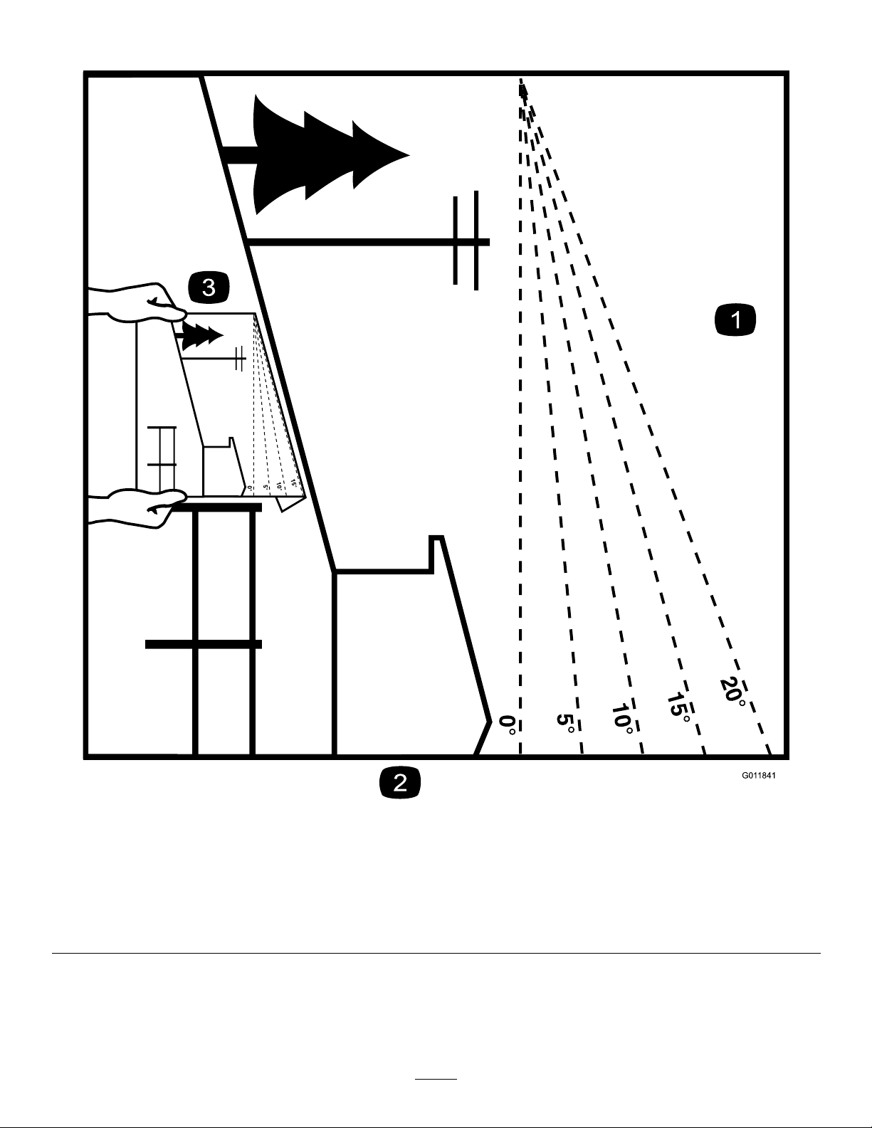
SlopeIndicator
G011841
Figure3
Thispagemaybecopiedforpersonaluse.
1.Themaximumslopeyoucansafelyoperatethemachineonis15degrees.Usetheslopecharttodeterminethedegreeofslope
ofhillsbeforeoperating.Donotoperatethismachineonaslopegreaterthan15degrees.Foldalongtheappropriateline
tomatchtherecommendedslope.
2.Alignthisedgewithaverticalsurface,atree,building,fencepole,etc.
3.Exampleofhowtocompareslopewithfoldededge.
8
Page 9
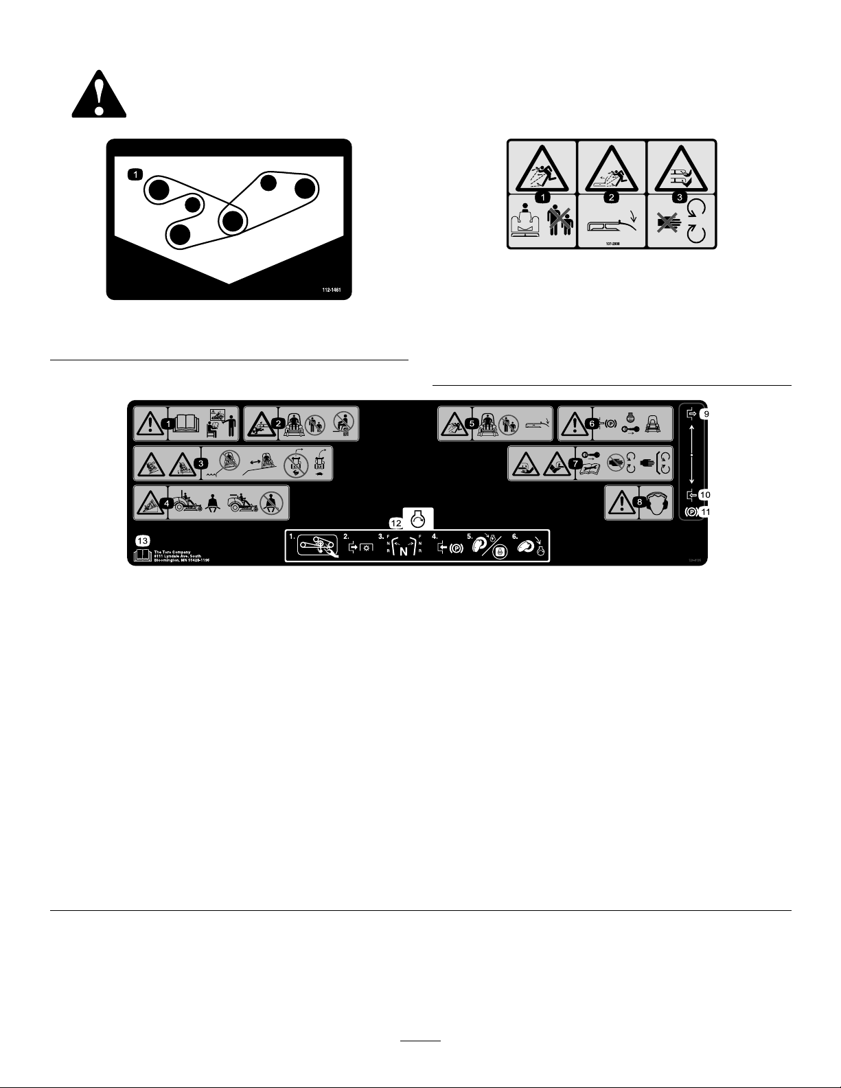
SafetyandInstructionalDecals
Safetydecalsandinstructionsareeasilyvisibletotheoperatorandarelocatednearanyareaofpotential
danger.Replaceanydecalthatisdamagedorlost.
112-1461
1.Beltrouting
107-2908
1.Thrownobjecthazard—keepbystandersasafedistance
fromthemachine.
2.Thrownobjecthazard—donotoperatethemowerwiththe
deectoruporremoved,keepthedeectorinplace.
3.Cutting/dismembermenthazardofhandorfoot,mower
blade—stayawayfrommovingparts.
1.Warning—readtheOperator'sManualbeforeoperatingand
donotoperatethismachineunlessyouaretrained.
2.Crushing/dismembermenthazardofbystanders—donot
carrypassengers,keepbystandersasafedistancefromthe
machine.
3.Tipping,dropoffhazard—donotoperatenearwaterdrop-offs,
stayasafedistancefromdrop-offs,slowmachinebefore
turning,donotturnathighspeeds,
4.WearaseatbeltwhenaROPSisinplace,donotwearaseat
beltwhenROPSislowered.
5.Thrownobjecthazard—keepbystandersasafedistancefrom
themachine;keepalldeectorsandshieldsinplace.
6.Warning—engagetheparkingbrake,stoptheengineand
removetheignitionkeybeforeleavingthemachine.
7.Cuttinghazardofhandorfoot—removetheignitionkey
andreadtheinstructionsbeforeservicingorperforming
maintenance,keepawayfrommovingparts.
120-9195
8.Warning—wearhearingprotection.
9.Engage
10.Disengage
11.Parkingbrake
12.Tostarttheengine:clearanydebrisfromtheattachment,
disengagethePTO,movethemotioncontrolleverstothe
neutralposition,engagetheparkingbrake,turntheignitionto
Runandwaitfortheglowpluglighttoturnoff,turntheignition
keytoStart.
13.ReadtheOperator'sManual.
9
Page 10
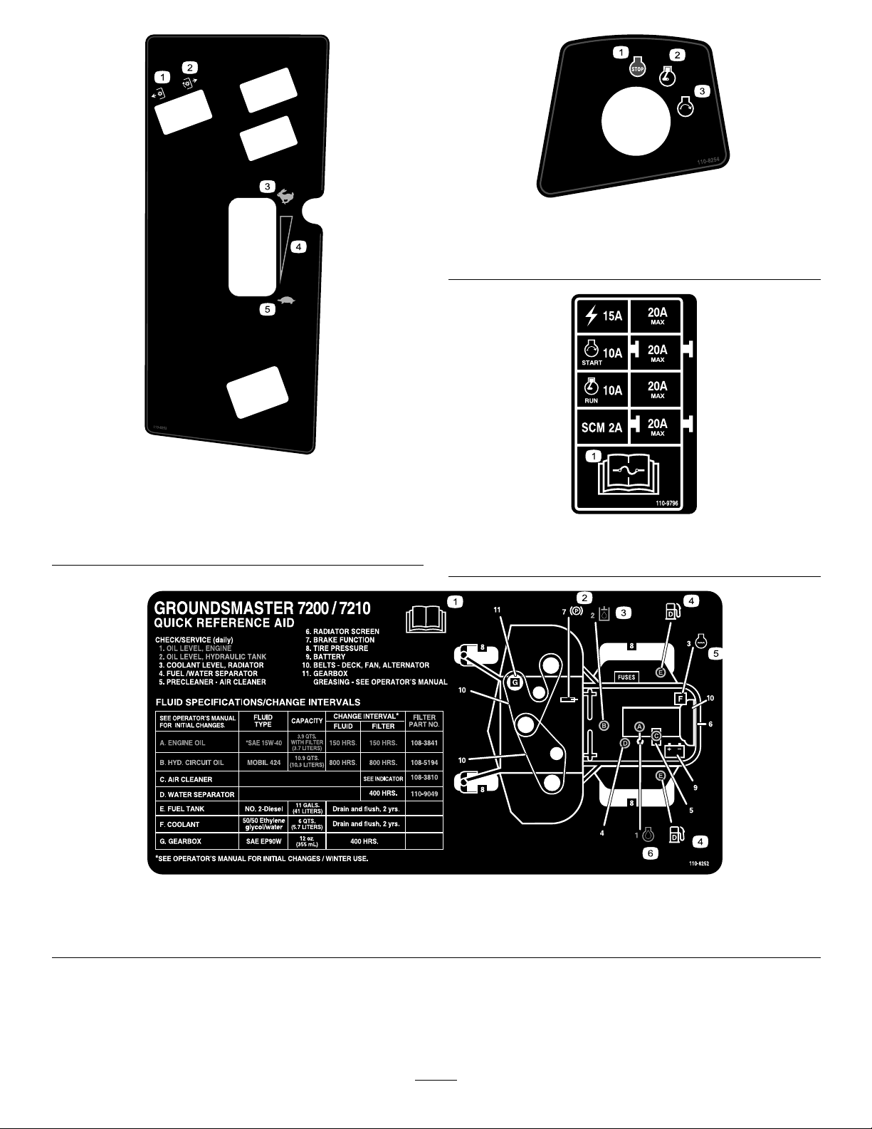
110-8254
1.Engine–Stop3.Engine—Start
2.Engine—Run
110-8253
1.PTO–Off4.Continuousvariable
setting
2.PTO—On5.Slow
3.Fast
110-9796
1.ReadtheOperator'sManualforinformationonfuses.
110-8252
1.ReadtheOperator'sManual.
2.Parkingbrake4.Fuel6.Engineoil
3.Hydraulicoil5.Enginecoolant
10
Page 11
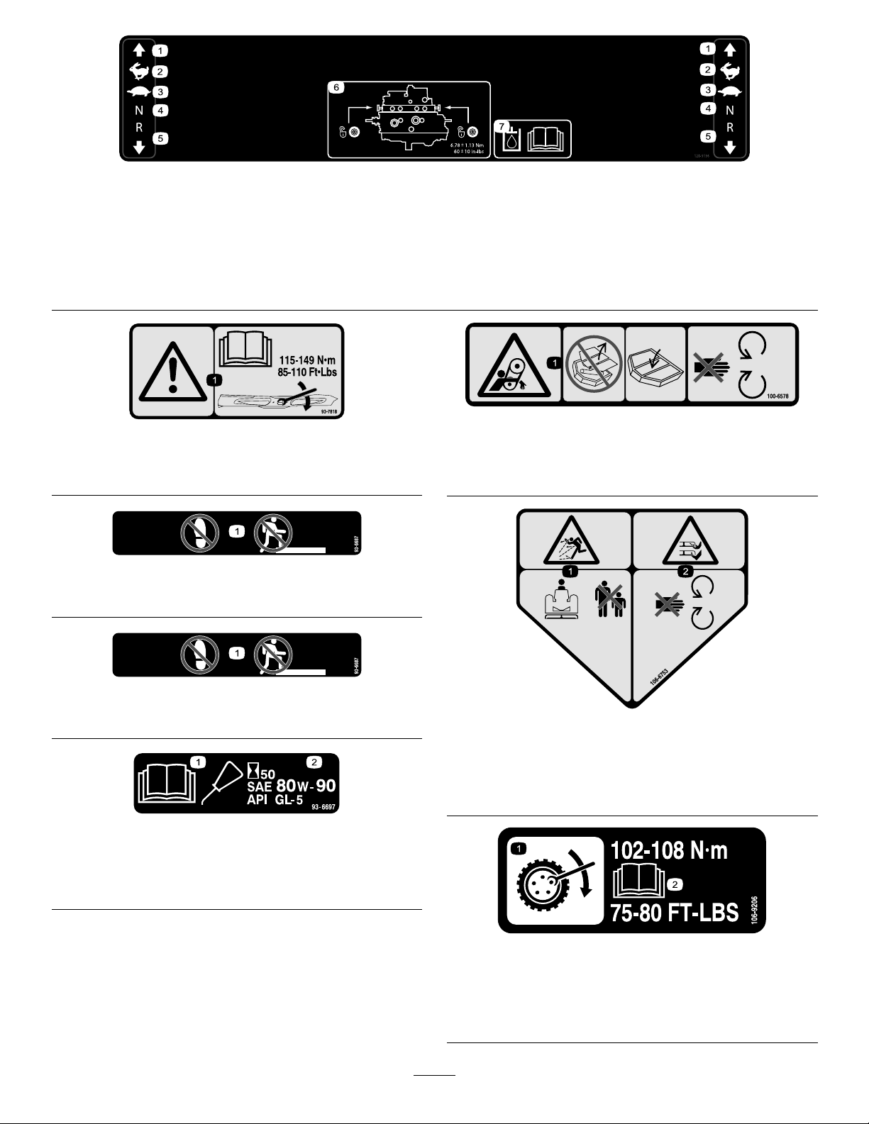
120-9196
1.Forward
2.Fast4.Neutral6.Towvalvelocation;torque
3.Slow
5.Reverse
thetowvalvesto6.78±
1.13N⋅m(60±10in-lbs).
93-7818
1.Warning—readtheOperator'sManualforinstructionson
torquingthebladebolt/nutto115-149N-m(85-110ft-lb).
1.Entanglementhazard,belt—donotoperatethemachine
withtheshieldsorguardsremoved;alwayskeeptheshields
andguardsinplace;stayawayfrommovingparts.
93–6696
1.Storedenergyhazard—readtheOperator'sManual.
7.ReadtheOperator's
Manualformore
informationonthehydraulic
oil.
100-6578
1.Donotstephere.
1.ReadtheOperator's
Manual.
93-6687
106-6753
1.Thrownobjecthazard—keepbystandersasafedistance
fromthemachine.
2.Cutting/dismembermenthazardofhandorfoot,mower
blade—stayawayfrommovingparts.
93-6697
(Model30631)
2.AddSAE80w-90(API
GL-5)oilevery50hours.
106-6755
1.Enginecoolantunder
pressure.
2.Explosionhazard—read
theOperator'sManual.
3.Warning—donottouchthe
hotsurface.
4.Warning—readthe
Operator'sManual.
11
Page 12
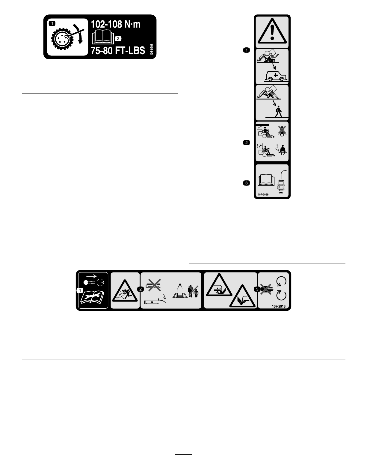
106-9206
1.Wheeltorquespecications
2.ReadtheOperator'sManual.
107-3069
1.Warning–thereisnorolloverprotectionwhentherollbaris
down.
2.Toavoidinjuryordeathfromarolloveraccident,keepthe
rollbarintheraisedandlockedpositionandweartheseat
belt.Lowertherollbaronlywhenabsolutelynecessary;do
notwearthetheseatbeltwhentherollbarisdown.
3.ReadtheOperator'sManual;driveslowlyandcarefully .
1.Removetheignitionkeyandreadthe
Operator'sManualbeforeservicingor
performingmaintenance.
107-2916
2.Thrownobjecthazard—donotoperate
themowerwiththedeectorupor
removed,keepthedeectorinplace;
keepbystandersasafedistancefrom
themachine.
12
3.Cutting/dismembermenthazardof
handorfoot,mowerblade—stayaway
frommovingparts.
Page 13

106-9290
1.Inputs5.Inseat
2.Notactive
3.Hightemperatureshutdown
6.PowerTake-off(PTO)10.PowerTakeOff(PTO)
7.ParkingbrakeOff11.Start
4.Hightemperaturewarning8.Neutral
9.Outputs13.Start
12.EnergizetoRun(ETR)
110-9781
1.Warning—readtheOperator'sManual.
2.Poisonandcausticliquid/chemicalburnhazard—keepchildrenasafedistancefromthebattery.
3.Warning—donottouchthehotsurface.
4.Cutting/dismembermenthazard,fanandentanglementhazard,belt—stayawayfrommovingparts.
5.Hydraulicoilinsystemunderpressure,escapinghydraulicoilpenetratingskinhazard,brokenhydrauliclineshazard—wear
protectivehandprotectionwhenhandlinghydraulicsystemcomponents.
14.Power
106-6754
1.Warning—donottouchthehotsurface.
2.Cutting/dismembermenthazard,fanandentanglement
hazard,belt—stayawayfrommovingparts.
112-1689
CEMarkedModelsOnly(WiththeCEKitInstalled)
safetydecalincludesaslopewarningrequiredonthemachineforcompliancetothe
EuropeanLawnMowerSafetyStandardEN836:1997.Theconservativemaximum
slopeanglesindicatedforoperationofthismachineareprescribedbyandrequiredby
thisstandard.
1.Tippinghazard—donotoperateonslopesgreaterthan14
degrees.
13
*This
Page 14
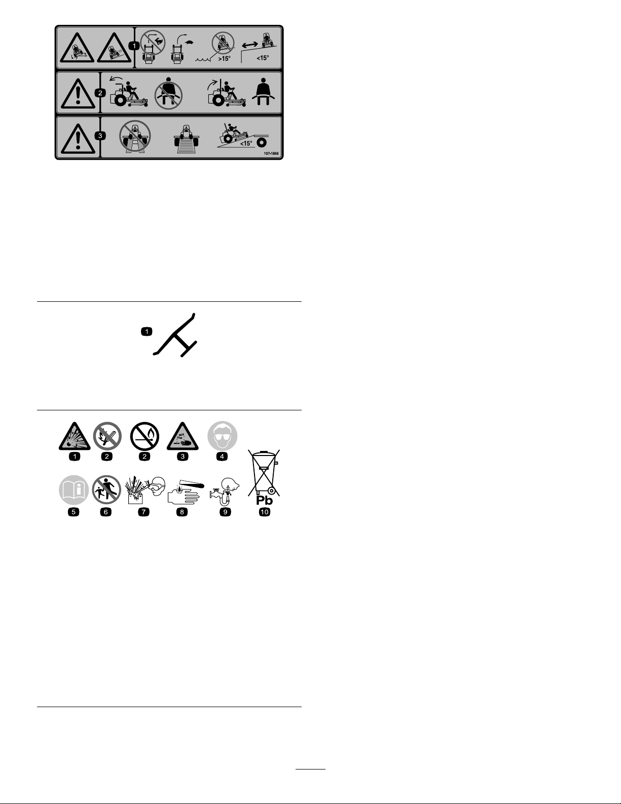
107-1866
1.Tippinghazardandslidingorlossofcontrolhazard,
drop-offs—donotturnsharplywhiletravelingfast,instead,
slowdownandturngradually ,donotoperatethemachine
neardrop-offs,slopesgreaterthan15degrees,orwater;
keepasafedistancefromdrop-offs.
2.Warning—iftherollbarislowered,donotweartheseat
belt,iftherollbarisraised,weartheseatbelt.
3.Warning—donotusesplitramps,useafullrampswhen
transportingmachine,onlyuserampswithinclinesless
than15degrees.
Manufacturer'sMark
1.Indicatesthebladeisidentiedasapartfromtheoriginal
machinemanufacturer.
BatterySymbols
Someorallofthesesymbolsareonyourbattery
1.Explosionhazard
2.Nore,opename,or
smoking.
3.Causticliquid/chemical
burnhazard
4.Weareyeprotection9.Flusheyesimmediately
5.ReadtheOperator's
Manual.
6.Keepbystandersasafe
7.Weareyeprotection;
8.Batteryacidcancause
10.Containslead;donot
distancefromthebattery.
explosivegasescan
causeblindnessandother
injuries
blindnessorsevereburns.
withwaterandgetmedical
helpfast.
discard.
14
Page 15
Setup
G004634
1
2
3
4
5
LooseParts
Usethechartbelowtoverifythatallpartshavebeenshipped.
ProcedureDescription
1
2
3
4
5
6
Nopartsrequired
Nopartsrequired
Nopartsrequired
Nopartsrequired
MowerDeckorPolarTracKit(sold
separately)
Operator'sManual
EngineOperator'sManual
PartsCatalog
OperatorTrainingMaterial
Pre-deliveryInspectionSheet
Enginewarranty1
CEcerticate
Qty.
Use
–
–
–
–
1
1
1
1
1
1
1
AdjusttheROPS.
Installweights.
Checkthehydraulicuid,engineoil,
andcoolantlevels.
Activateandchargethebattery.
Installthemowerdeck/polartrac.
Readthemanualsandviewthe
trainingmaterialsbeforeoperatingthe
machine.Usetheremainingpartsfor
theinstallationofattachments.
AdjustingtheROPS
NoPartsRequired
Procedure
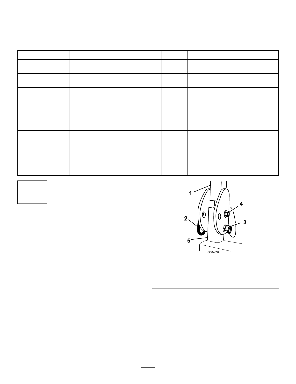
1.Removethehairpincotterpinsandremovethe2pins
1
fromtherollbar(Figure4).
Figure4
RightSideShown
1.Rollbar3.Hairpincotterpin
2.Pin
2.Raisetherollbartotheuprightpositionandinstallthe
2pinsandsecurethemwiththehairpincotterpins
(Figure4).
Note:Ifyoumustlowertherollbar,pushthebar
forwardtorelievepressureonthepins,removethe
pins,lowerthebarslowly,andsecureitwiththepinsso
thatitdoesnotdamagethehood.
15
Page 16

2
InstallingWeights(forCECompliance)
NoPartsRequired
Procedure
Machineswith72-inchdecksinstalledandnootherattachments,donotneedaddedweighttomeetCEstandards.However,
youmayneedtopurchaseandinstalladditionalweightdependingonthemowerdecksize/typeandtheattachmentsthat
youinstallonthemachine.Thefollowingtableliststhevariousattachmentcongurationsandtheadditionalfrontweight
neededforeachmodel:
AttachmentConguration
Groundsmaster7200/7210
TractionUnitwithnoAdded
Attachments
Groundsmaster7200/7210
TractionUnitandHardCanopy
Groundsmaster7200/7210
TractionUnit,HardCanopy ,and
RoadLightKit
Groundsmaster7200/7210
TractionUnit,HardCanopy ,
RoadLightKit,andJackStand
Groundsmaster7200/7210
TractionUnit,HardCanopy ,and
JackStand
Groundsmaster7200/7210
TractionUnit,RoadLightKit,
andJackStand
Groundsmaster7200/7210
TractionUnitandRoadLightKit
Groundsmaster7200/7210
TractionUnitandJackStand
WeightRequiredwitha62
inch(157.5cm)Guardian
Mower
22lb(10kg)0lb(0kg)0lb(0kg)
75lb(34kg)21lb(9.5kg)33lb(15kg)
71lb(32.2kg)63lb(28.5kg)22lb(10kg)
40lb(18kg)37lb(17kg)22lb(10kg)
31lb(14kg)22lb(10kg)22lb(10kg)
0lb(0kg)0lb(0kg)0lb(0kg)
25lb(11.3kg)0lb(0kg)0lb(0kg)
0lb(0kg)0lb(0kg)0lb(0kg)
WeightRequiredwitha72
inch(183cm)GuardianMower
inch(183cm)Side-discharge
WeightRequiredwitha72
Mower
ContactyourAuthorizedToroDistributortoobtaintheappropriatekitsandweightsforyourmachine.
16
Page 17

3
CheckingFluidLevels
NoPartsRequired
Procedure
1.Checkthehydraulicuidlevelbeforestartingthe
engine;refertoCheckingtheHydraulicSystem(page
30).
2.Checktheengineoillevelbeforeandafterstartingthe
engine;refertoCheckingtheEngineOilLevel(page
.
30)
3.Checkthecoolingsystembeforestartingtheengine;
refertoCheckingtheCoolingSystem(page53).
3.Carefullylleachcellwithelectrolyteuntiltheplates
arecoveredwithabout6mm(1/4inch)ofuid(Figure
6).
Figure6
4.Allowapproximately20to30minutesforthe
electrolytetosoakintotheplates.
4
ActivatingandChargingthe Battery
NoPartsRequired
Procedure
Useonlyelectrolyte(1.265SpecicGravity)tollbattery
initially.
1.Removethebatteryfromthemachine.
Important:Donotaddelectrolytewhilethe
batteryisinthemachine.Y oucouldspillit,
causingcorrosion.
2.Cleanthetopofthebatteryandremovetheventcaps
(Figure5).
WARNING
Chargingthebatteryproducesgassesthat
canexplode,andcouldcauseseriousinjury
ordeath.
Neversmokenearthebatteryandkeepsparks
andamesawayfrombattery.
5.Rellasnecessarytobringtheelectrolytetowithin
about6mm(1/4inch)ofthebottomofthellwell
(Figure6).
6.Connecta3-to-4ampbatterychargertothebattery
posts.Chargethebatteryatarateof3to4amps
untilthespecicgravityis1.25orhigherandthe
temperatureisatleast16°C(60°F)withallcells
gassingfreely.
7.Whenthebatteryischarged,disconnectthecharger
fromtheelectricaloutletandbatteryposts.
Note:Afterthebatteryhasbeenactivated,add
onlydistilledwatertoreplacenormalloss,although
maintenance-freebatteriesshouldnotrequirewater
undernormaloperatingconditions.
1.Ventcaps
Figure5
17
Page 18
WARNING
CALIFORNIA
Proposition65Warning
Note:Ensurethatthebatterycablesareroutedaway
fromanysharpedgesormovingparts.
Batteryposts,terminals,andrelated
accessoriescontainleadandleadcompounds,
chemicalsknowntotheStateofCalifornia
tocausecancerandreproductiveharm.
Washhandsafterhandling.
WARNING
Batteryterminalsormetaltoolscouldshort
againstmetaltractorcomponentscausing
sparks.Sparkscancausethebatterygassesto
explode,resultinginpersonalinjury.
•Whenremovingorinstallingthebattery,
donotallowthebatteryterminalstotouch
anymetalpartsofthemachine.
•Donotallowmetaltoolstoshortbetween
thebatteryterminalsandmetalpartsof
themachine.
8.Installthebatteryintothemachineandsecureit.
5
InstallingtheMower Deck/PolarTrac
Partsneededforthisprocedure:
1
MowerDeckorPolarTracKit(soldseparately)
InstallingaMowerDeckKit
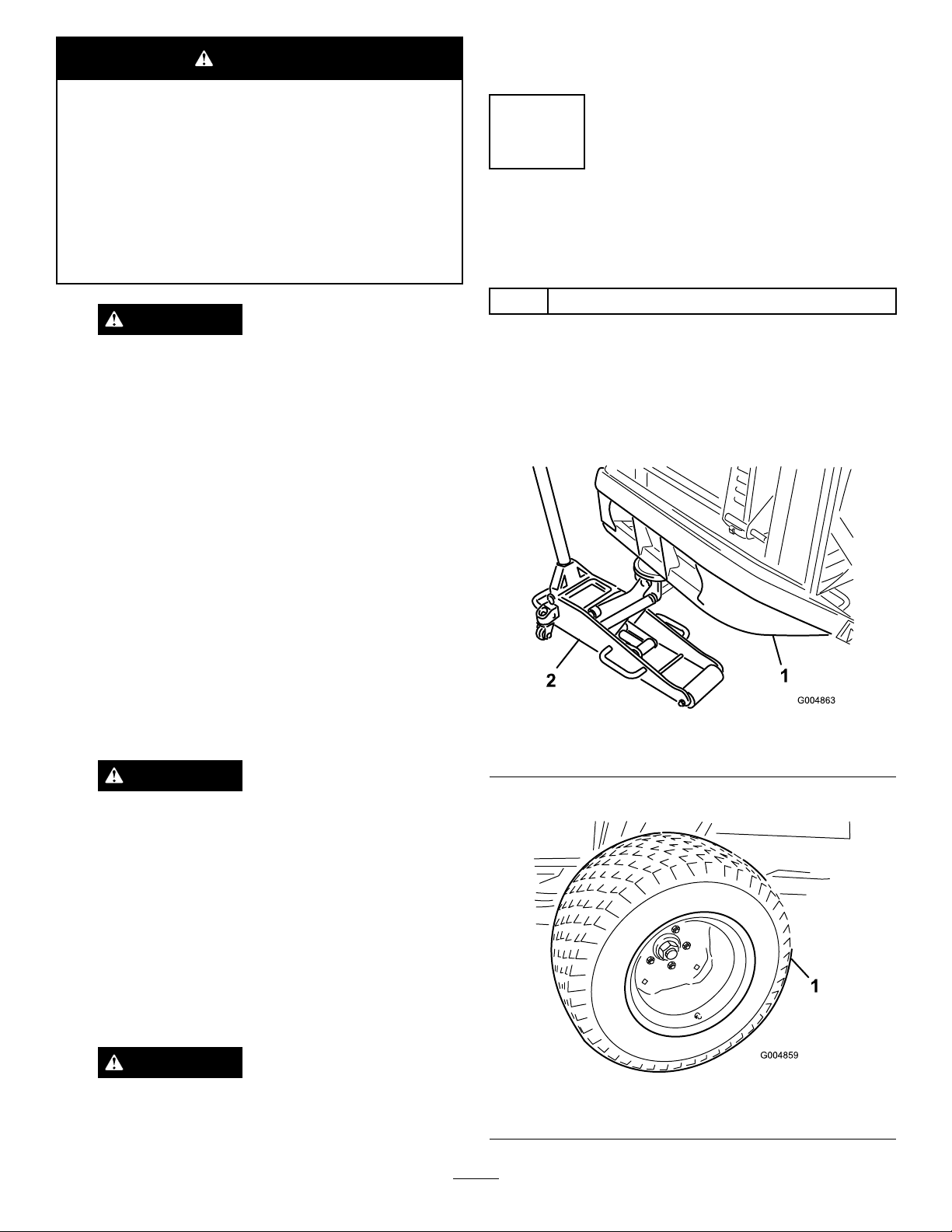
1.Removethetractionunitfromtheshippingpallet.
2.Placeajackstandundereachwheelmotorandaoor
jackundertherearbumper(Figure7),orsuspendfrom
aover-headhoist.
Note:Thebatteryshouldnotmoveorwigglewhen
pushed.
9.First,installthepositivecable(red)tothepositive(+)
terminalandthenthenegativecable(black)tothe
negative(-)terminalofthebattery.Slidetherubber
bootoverthepositiveterminaltopreventapossible
shortfromoccurring.
WARNING
Incorrectbatterycableroutingcoulddamage
themachineandcablescausingsparks.
Sparkscancausethebatterygassesto
explode,resultinginpersonalinjury.
•Alwaysdisconnectthenegative(black)
batterycablebeforedisconnectingthe
positive(red)cable.
•Alwaysconnectthepositive(red)battery
cablebeforeconnectingthenegative
(black)cable.
Figure7
1.Rearbumper2.Floorjack
3.Installthedrivetires(Figure8).
WARNING
Connectingcablestothewrongpostcould
damagetheelectricalsystemandresultin
personalinjury.
Figure8
1.Drivetire
18
Page 19
4.Rollthedeckandframeintopositionandinstallthe
5bolts(3/4inch),washersandnutsthatconnectthe
deckframetotherearframe.
5.Removethemountingbracketandsupporttubetogain
accesstotheboltsontheright-handside(Figure9).
Figure9
1.Mountingbracket
2.Supporttube
6.Torquetheboltsto265ft-lbs(359N-m).
7.Removetheclevispinsandthe8mm(5/16
inch)self-tappingscrewpinretainerssecuringthe
vertical-tubesupportassembliestotherearofthedeck
frame.
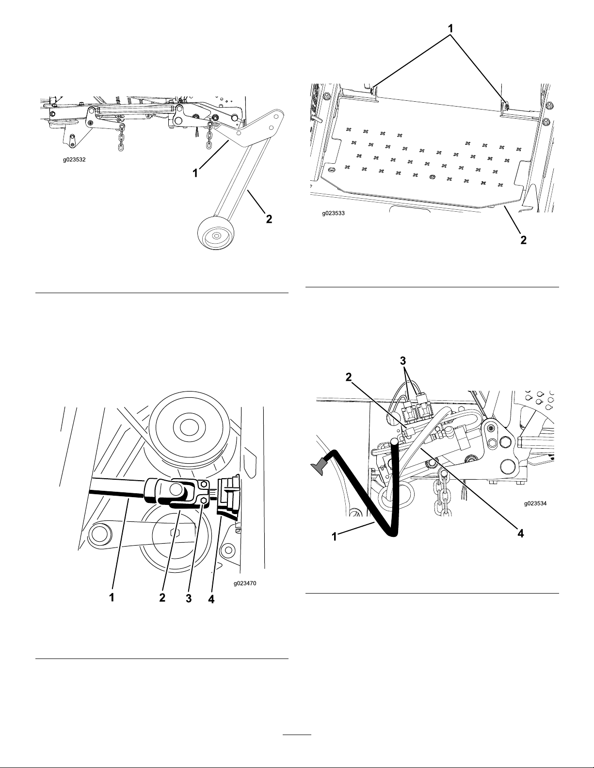
8.Slidethedriveshaftontothegearboxshaft(Figure10).
Figure11
1.Clevispins
2.Floorplate
11.Routeandconnectthehydraulic-pressurehoseand
tankhosetothecontrolvalve(Figure12).
12.Connecttheelectricalwirestotheelectricalconnectors
(Figure12).
Figure10
1.Driveshaft3.Bolt(5/16inch)
2.Rollpin
4.Gearbox
9.Installtherollpin,andtorquetheboltsto175to225
inch-lbs(20to25N-m).
10.Installtheoorplateusingthe2clevispins(Figure11).
Figure12
1.Tankhose3.Electricalconnectors
2.Controlvalve
4.Pressurehose
13.Installtherearofthedeck-liftcylinderontothepivot
pinandsecureitwiththeretainingring(Figure13).
14.Securethefrontoftheliftcylindertothemowerframe
withthecylinderpinandscrew(Figure13).
19
Page 20
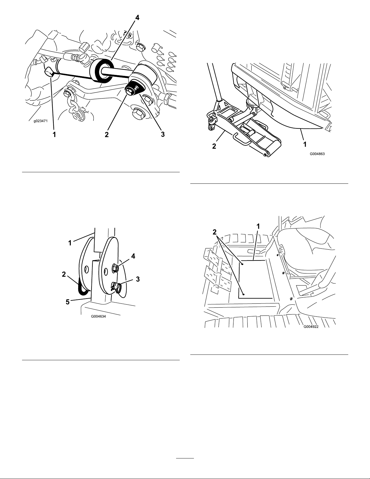
Figure13
G004634
1
2
3
4
5
InstallingthePolarTracKit
1.Removethetractionunitfromtheshippingpallet.
2.Placeajackstandundereachwheelmotorandaoor
jackundertherearbumper(Figure15)orsuspendthe
tractionunitfromanoverheadhoist.
1.Retainingring
2.Screw4.Deck-liftcylinder
3.Cylinderpinandscrew
15.PositiontheROPSassemblyontotheROPSposts.
16.Installthebolt,nut,hairpincotterandpinsecuring
eachROPSassemblytotheROPSposts(Figure14).
Note:Ifinstallinganalliedsuppliersmowerdeck,
installROPSKit,partno.117–9179.
Figure14
1.ROPS
2.Pin
3.Cotterpin
4.Boltandnut
5.ROPSpost
Figure15
1.Rearbumper2.Floorjack
3.Removethe2screwssecuringthewinterframe
oor-platecovertotheoor,andremovetheplate
(Figure16).
Figure16
1.Floor-platecover2.Mountingscrews
17.Startthemachine,raiseandlowerthedeck,checkfor
leaks,andensurethatthehosesdonotrubagainstthe
whileroutingthedriveshaftthroughtheframetube
(Figure17).
frame.
4.Carefullyrollthewinter-frameassemblyintoposition
20
Page 21

Figure17
5.Routethehosesasfollows:
A.Routethetankhoseundertheliftcylinderand
betweenthecylinder-mountingbracketstothe
valve(Figure19).
B.RoutethepressurehosealongsidethePTOshaft
tothevalve(Figure19).
Note:Toemphasizethehoserouting,thehoses
areshownwithoutthehosecoversinstalled.
1.Driveshaft
2.Frametube
Note:Iftherearofthecabisnothighenoughtoclear
thecontrolhandles,evenlytightenthejackingbolts
oneachsideofthecabjacktubetoraisetherearof
thecab(Figure18).
Figure19
1.Tankhose2.Pressurehose
6.Connectthedriveshafttothegear-boxshaftinthe
winterframe,andtorquethebolts(5/16inch)to175
to225inch-lbs(20to25N-m).
7.Installtherollpin(Figure20).
1.Jackingbolts
Figure18
21
Page 22
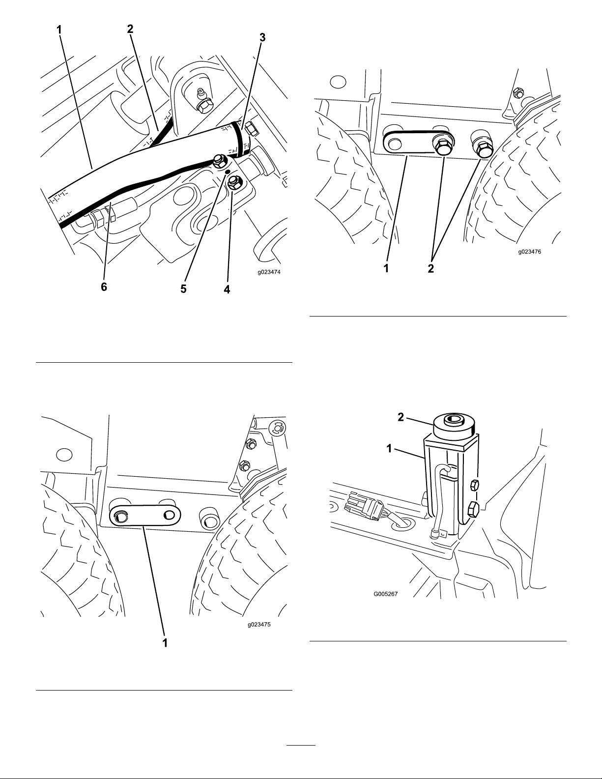
9.Adjusttheoorjacktoinstallthebolts(3/4inch)on
eachside(Figure22).Torquetheboltsto265ft-lb
(359N-m).
Figure22
Figure20
1.Tankhose
2.Pressurehose5.Rollpin
3.Cabletie
4.Bolt(5/16inch)
6.Hosecover
8.Adjusttheoorjacktolineupthe25mm(1inch)
holesintheframe,andinstallacouplerpinoneach
side(Figure21).
1.Couplerpin2.Bolt(3/4inch)
Note:Thereartireswillneedtoberemovedtotorque
therearbolts(3/4inch).Aftertorquingtheframe
bolts,installthereartiresandtorquethelugnutsto65
to85ft-lbs(88to115N-m).
10.Insertarubbermountontoeachcabmountatthe
rear-mountinglocations(
Figure23).
1.Couplerpin
Figure21
Figure23
1.Cabmount
2.Rubbermount
11.Lowerthecabintopositionbyslowlyandevenly
looseningthejackingboltsoneachendofthejacking
tube(Figure24).
22
Page 23
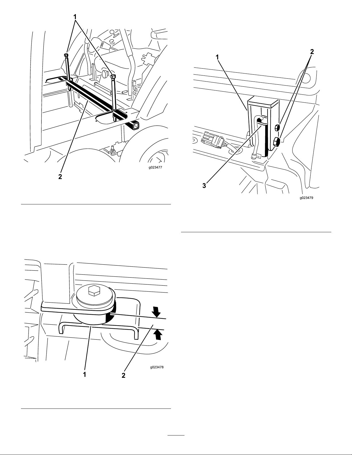
Figure24
14.Tightentheboltsandnutssecuringtherear-cab
mountstotheROPSposts(Figure26).
15.Adjusttheoorjackiftheboltsarebindingand
difculttoremove.
1.Jackingbolts
2.Cab-jacktube
12.Attherear-mountingpoints,securethecabtothe
machinewithabolt(1/2x3inch),steelwasher(1/2x
2–1/2inch),rubberwasher(1/2x2–1/2inches)and
nut(1/2inch)asshowninFigure25.
13.Tightenallfourcab-mountingboltsuntiltherubber
mountsarecompressedtoathicknessof7/8inch.
Figure26
1.Cabmount3.ROPSpost
2.Boltsandnuts
16.Loosenthejackingboltsandremovethecab-jacktube
fromthecutoutsinthecaboor(Figure27).
Figure25
1.Rubbermount2.Measurementarea—22
mm(7/8inch)
23
Page 24
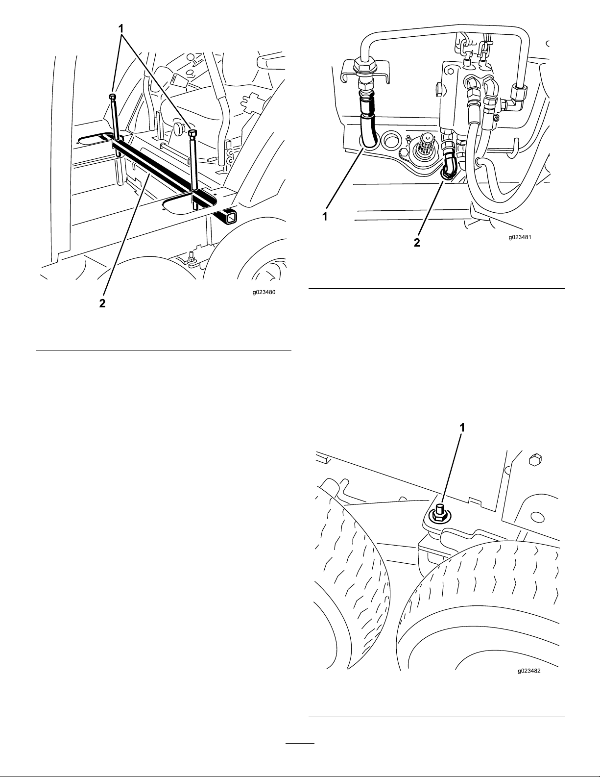
1.Jackingbolts
Figure27
2.Cab-jacktube
Figure28
1.Pressurehose2.Tankhose
18.Raisetherearofthemachineuntil2jackstandscanbe
positionedunderthereartubeataheightthatsupports
thereartires25to76mm(1to3inches)offofthe
ground.
17.Connectthehydraulic-pressurehosetothevalvehard
lineandthetankhosetothevalve(Figure28).
Retainthehoseplugsforthesummerchangeover.
Note:Makesurethehosesarenotekinkedorare
rubbingagainstanymovingparts.
Note:Adjusttheangleofthettingstoaccommodate
theroutingofthehoses.
19.Lowertheoorjacksotherearframerestsonthejack
stands.Positiontheoorjackunderthecenterofthe
frontliftarmpivottube.
20.Removethe1/2inchatwasherandthe1/2inchnut
installedonthestudonthebogiepivot(Figure29).
Figure29
1.1/2inchnutandatwasheronthebogie-pivotstud
24
Page 25
21.Raisetheoorjackuntilthefronttiresareoffofthe
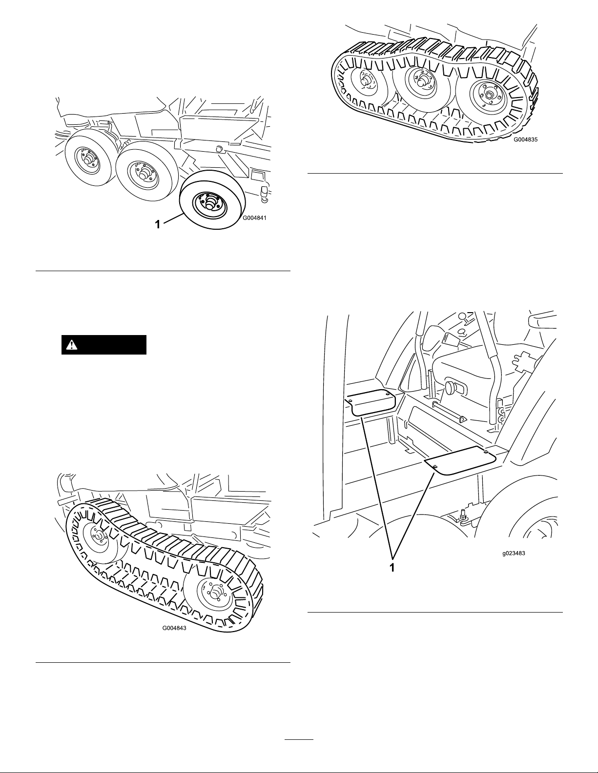
groundhighenoughtoinstallthetrackbeneaththem,
andsupporttheframewithjackstands.
22.Removethefrontandcentertiresfromthewinter
assembly(Figure30).
Figure30
1.Fronttire
Figure32
26.Lowertheoorjackuntilthefrontwheelssupportthe
frame.Installtheatwashers(1/2inch)andlocknuts
onthebogie-pivotstud(Figure29)andtorqueto75
ft-lbs(102N-m).
Note:Youmayneedtomovetheoorjacktotherear
bumpertoraisetherearofthemachinehighenoughto
installtheatwasherandlocknut.
23.Carefullyliftthetracksovertherearwheelandfront
hubs.Thedirectionofthetrackrotationisprinted
onthetrack.The‘V’designintherubbertrackmust
pointforward.
CAUTION
Thetrackguideshavemanypinchpoints.
Carefullygrasptherubbertrackontheouter
edgesoutboardofthesteelguideswhen
movingthetrack.
24.Adjusttheoorjacktoasuitableheighttoinstallthe
fronttire.Withanotherperson,liftthefrontofthe
trackenoughtocarefullyinstallthefronttires(Figure
31).
27.Installthesideaccesscoverswiththescrewspreviously
removed(Figure33).
Figure31
25.Adjusttheoorjacktoasuitableheighttoinstallthe
centertire.Liftthecenterofthetrackenoughtoinstall
thecentertire(Figure32).T orquethelugnutsto65to
85ft-lbs(88to115N-m).
Figure33
1.Accesscovers
28.Installthewinterframeoor-platecovertotheoor
withthescrewspreviouslyremoved(Figure34).
25
Page 26
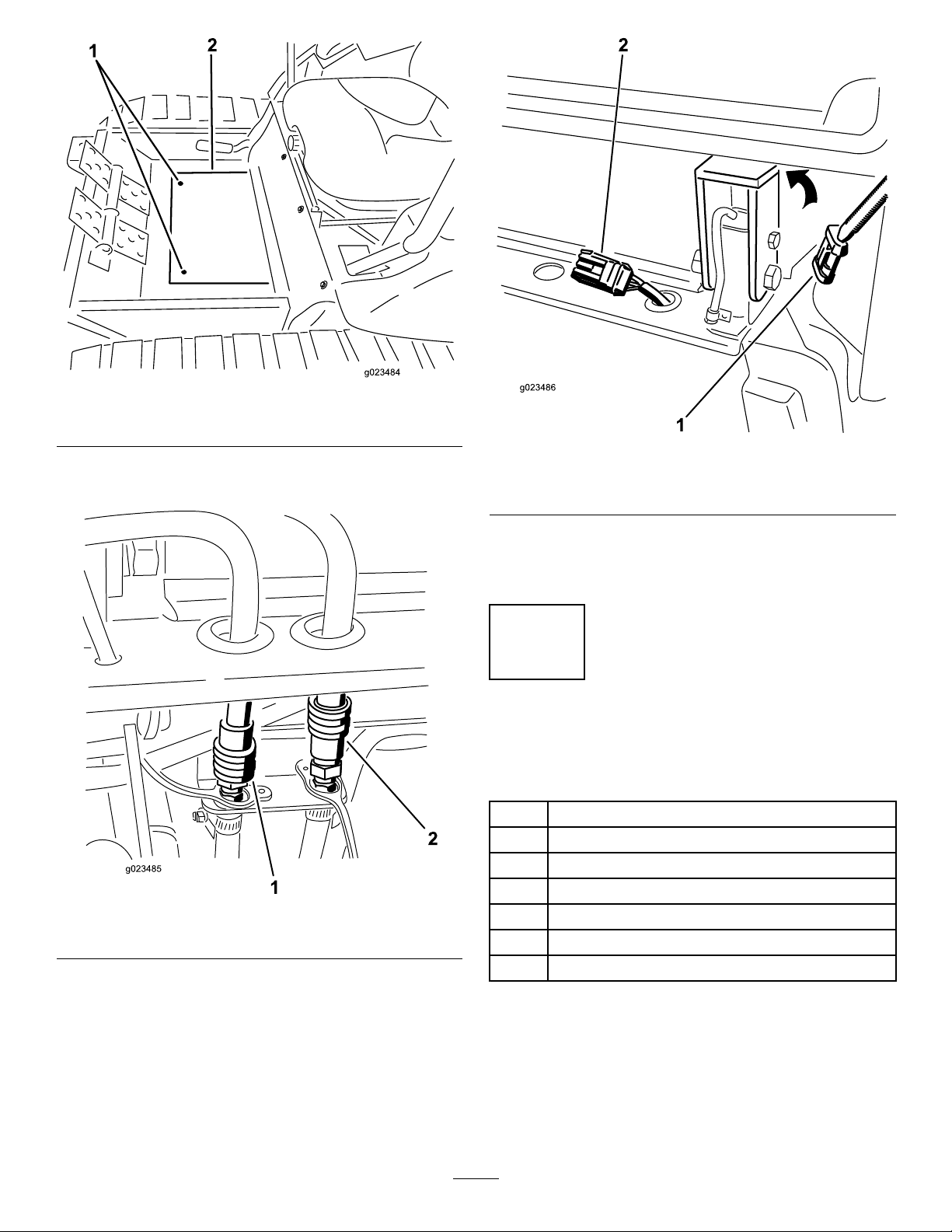
Figure34
1.Mountingscrews2.Floor-platecover
29.Connectthecabpressureandreturnhosestothequick
couplersontherearframemount(Figure35).
Figure35
1.Returnhose2.Pressurehose
30.Removethecapandplugthecabwireharness
connectorintotheharnessontherear-framemount
(
Figure36).
Figure36
1.Cabwireharness
connector
31.Startthemachine.Runtheliftarmupanddownand
checkforhydraulicleaks.Checktheantifreezelevel
andreplenishasrequired.
2.Harnessconnectoronthe
rear-framemount
6
ReadingtheManualsand ViewingtheTrainingMaterials
Partsneededforthisprocedure:
1
Operator'sManual
1
EngineOperator'sManual
1
PartsCatalog
1
OperatorTrainingMaterial
1
Pre-deliveryInspectionSheet
1Enginewarranty
1
CEcerticate
Procedure
1.Readthemanuals.
2.Viewtheoperatortrainingmaterials.
26
Page 27
ProductOverview
1
2
3
4
5
6
4
G020877
G020866
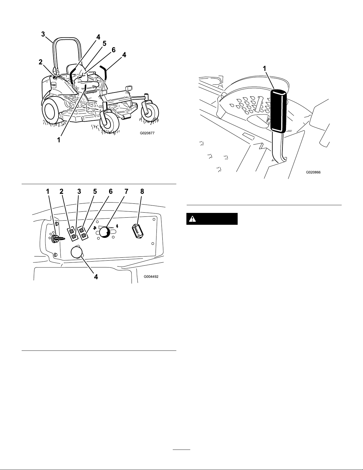
Figure37
1.Parkingbrakelever4.Motioncontrollever
2.Fuelcap(bothsides)5.Seat
3.Rollbar
6.Seatbelt
ParkingBrakeLever
Whenevertheengineisshutoff,engagetheparkingbraketo
preventaccidentalmovementofthemachine.Toengagethe
parkingbrake,pulltheparkingbrakeleverrearwardandup
(Figure39).Toreleasetheparkingbrake,pushtheparking
brakeleverforwardanddown.
Figure39
1.Parkingbrakelever
CAUTION
Donotparkthetractionunitonaslope.
IgnitionSwitch
Theignitionswitchhas3positions:Off,On/Preheat,and
Start.
Figure38
1.Ignitionswitch
2.Enginecoolant
temperaturewarning
light
3.Glowpluglight
4.Powertakeoff(PTO)
Switch
Controls
Becomefamiliarwithallthecontrolsbeforeyoustartthe
engineandoperatethemachine(Figure37andFigure38).
5.Oilpressurewarninglight
6.Chargeindicatorlight
7.Throttlelever
8.Hourmeter
ThrottleLever
Thethrottlelevercontrolsthespeedoftheengine.Moving
thethrottleleverforwardtowardtheFastpositionincreases
theenginespeed.MovingitrearwardtowardtheSlow
positiondecreasestheenginespeed.Thethrottlecontrolsthe
speedofthebladesand,inconjunctionwithmotioncontrol
levers,controlsgroundspeedofthemachine.Alwaysrunthe
machinewiththethrottleintheFastpositionwhencutting
grass.
PowerTakeOff(PTO)Switch
Thepowertake-off(PTO)switchstartsandstopsthemower
blades.
MotionControlLevers
Themotioncontrolleverscontroltheforwardandrearward
motionsaswellastheturningofthemachine.Referto
DrivingtheMachine(page33).
HourMeter
Thehourmeterrecordsthenumberofhourstheengine
hasoperated.ItoperateswhenthekeyswitchisintheRun
position.Usethesetimesforschedulingregularmaintenance.
27
Page 28
Glow-PlugLight(OrangeLight)
Specications
Theglow-plugindicatorlightturnsonwhentheignition
switchisturnedtotheOnposition.Itremainslitfor6
seconds.Whenthelightturnsoff,theengineisreadytostart.
Engine-Coolant-TemperatureWarning
Light
Thislightglowsandthecuttingbladesstopiftheengine
coolanttemperatureishigh.Ifthemachineisnotstopped
andthecoolanttemperaturerisesanother20°F,theengine
willstop.
Important:Ifthemowerdeckshutsdownandthe
temperaturewarninglightison,pushPTOknobdown,
drivetoasafeatarea,movethethrottlelevertothe
Slowposition,movethemotioncontrolleversintothe
neutrallockedposition,andengagetheparkingbrake.
Allowtheenginetoidleforseveralminuteswhileitcools
toasafelevel.Stoptheengineandcheckthecooling
system;refertoCheckingtheCoolingSystem(page30).
TheChargeIndicator
Illuminateswhenthesystemchargingcircuitmalfunctions.
Note:Specicationsanddesignaresubjecttochange
withoutnotice.
Length
Width(RearWheels)57inches(144.8cm)
Height(RollBarUp)72inches(182.9cm)
Height(RollBarDown)48inches(121.9cm)
Weight,Model30360,30363,
30363TE,30363TC
Weight,Model30461and
30464
Weight,Model30462and
30465
Weight,Model30467and
30468
97inches(246.4cm)
2230lb(101 1kg)
2206lb(1000kg)
2151lb(975kg)
2140lb(971kg)
Attachments/Accessories
AselectionofToroapprovedattachmentsandaccessoriesis
availableforusewiththemachinetoenhanceandexpand
itscapabilities.ContactyourAuthorizedServiceDealeror
Distributororgotowww .Toro.comforalistofallapproved
attachmentsandaccessories.
Oil-PressureWarningLight
Theoil-pressurewarninglightglowswhentheoilpressure
inenginedropsbelowasafelevel.Iflowoilpressureever
occurs,stoptheengineanddeterminethecause.Repairthe
damagebeforestartingtheengineagain.
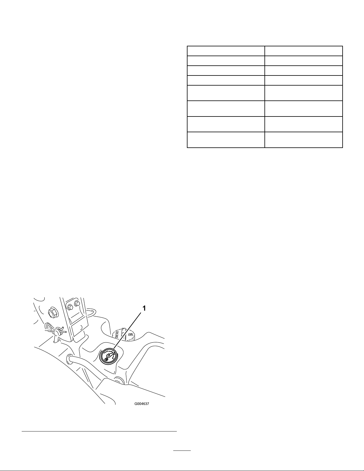
FuelGauge
Thefuelgauge(Figure40)indicatesthequantityoffuel
remaininginthefueltanks.
1.Fuelgauge
Figure40
28
Page 29

Operation
Note:Determinetheleftandrightsidesofthemachine
fromthenormaloperatingposition.
CAUTION
Thismachineproducessoundlevelsinexcessof85
dBAattheoperator’searandcancausehearingloss
throughextendedperiodsofexposure.
Wearhearingprotectionwhenoperatingthis
machine.
AddingFuel
Useonlyclean,freshdieselfuelwithultralow(<15
ppm)sulfurcontentmeetingASTMD975orEN590
specications.Theminimumcetaneratingshouldbe40.
Purchasefuelinquantitiesthatcanbeusedwithin180days
toensurefuelfreshness.
Important:Useofnon-ultralowsulfurfuelwillcause
damagetotheengineemissionsystem.
Fueltankcapacity:43.5liters(11.5USgallons)
Usesummergradedieselfuel(No.2-D)attemperatures
above20°F(-7°C)andwintergrade(No.1-DorNo.
1-D/2-Dblend)belowthattemperature.Useofwintergrade
fuelatlowertemperaturesprovideslowerashpointand
coldowcharacteristicswhichwilleasestartingandreduce
fuellterplugging.
Useofsummergradefuelabove20°F(-7°C)willcontribute
towardlongerfuelpumplifeandincreasedpowercompared
towintergradefuel.
Important:Donotusekeroseneorgasolineinsteadof
dieselfuel.Failuretoobservethiscautionwilldamage
theengine.
WARNING
Fuelisharmfulorfatalifswallowed.Long-term
exposuretovaporscancauseseriousinjuryand
illness.
•Avoidprolongedbreathingofvapors.
•Keepfaceawayfromnozzleandfueltankor
conditioneropening.
•Keepfuelawayfromeyesandskin.
•Paintedsurfacesmaybedamagedbybiodieselblends.
•Monitorseals,hoses,gasketsincontactwithfuelasthey
maybedegradedovertime.
•Fuellterpluggingmaybeexpectedforatimeafter
convertingtobiodieselblended.
•Contactyourdistributorifyouwishmoreinformation
onbiodiesel.
DANGER
Incertainconditions,fuelisextremelyammable
andhighlyexplosive.Areorexplosionfromfuel
canburnyouandothersandcandamageproperty.
•Fillthefueltankoutdoors,inanopenarea,when
theengineiscold.Wipeupanyfuelthatspills.
•Neverllthefueltankinsideanenclosedtrailer.
•Neversmokewhenhandlingfuel,andstayaway
fromanopenameorwherefuelfumesmaybe
ignitedbyaspark.
•Storefuelinanapprovedcontainerandkeepit
outofthereachofchildren.Neverbuymore
thana180-daysupplyoffuel.
•Donotoperatemachinewithoutentireexhaust
systeminplaceandinproperworkingcondition.
DANGER
Incertainconditionsduringfueling,static
electricitycanbereleasedcausingasparkwhich
canignitethefuelvapors.Areorexplosionfrom
fuelcanburnyouandothersandcandamage
property.
•Alwaysplacefuelcontainersonthegroundaway
fromyourvehiclebeforelling.
•Donotllfuelcontainersinsideavehicleoron
atruckortrailerbedbecauseinteriorcarpets
orplastictruckbedlinersmayinsulatethe
containerandslowthelossofanystaticcharge.
•Whenpractical,removeequipmentfromthe
truckortrailerandrefueltheequipmentwithits
wheelsontheground.
BiodieselReady
Thismachinecanalsouseabiodieselblendedfuelofupto
B7(7%biodiesel,93%petrodiesel).Thepetrodieselportion
mustbeultralowsulfur.Observethefollowingprecautions:
•Thebiodieselportionofthefuelmustmeetspecication
ASTMD6751orEN14214.
•TheblendedfuelcompositionshouldmeetASTMD975
orEN590.
•Ifthisisnotpossible,thenrefuelsuch
equipmentonatruckortrailerfromaportable
container,ratherthanfromafueldispenser
nozzle.
•Ifafueldispensernozzlemustbeused,keepthe
nozzleincontactwiththerimofthefueltank
orcontaineropeningatalltimesuntilfuelingis
complete.
29
Page 30
FillingtheFuelTank
UsingtheRolloverProtection
1.Parkthemachineonalevelsurface.
Important:Thefueltanksareconnected,butthe
fueldoesnottransferquicklyfromonetanktothe
other.Itisimportantwhenllingthatyoupark
onalevelsurface.Ifyouparkonahill,youmay
inadvertentlyoverllthetanks.
2.Shuttheengineoffandsettheparkingbrake.
3.Cleanaroundeachfueltankcapandremovethecap.
Important:Donotopenthefueltankswhen
parkedonahill.Thefuelcouldspillout.
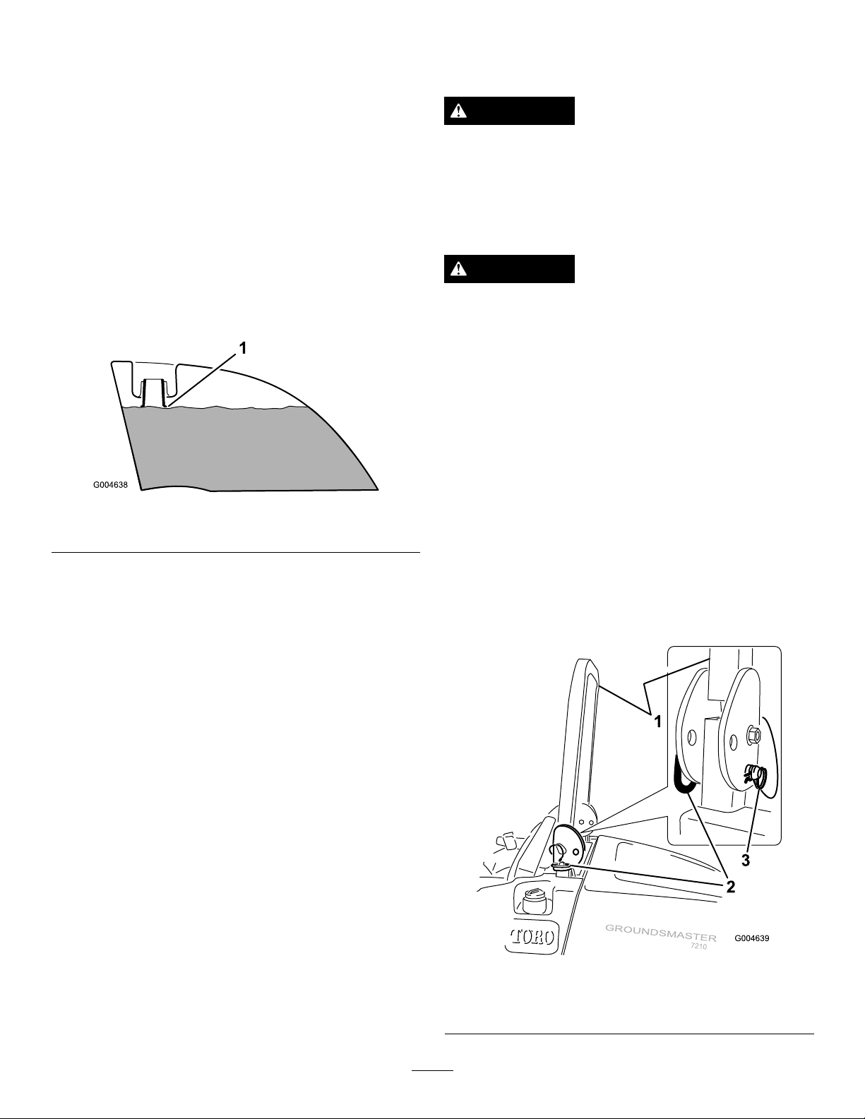
4.Addfueltobothfueltanks,untilthelevelisevenwith
thebottomofthellerneck(Figure41).Donotover
llthefueltanks.
Figure41
1.Bottomofthellerneck
5.Installthefueltankcapssecurely.Wipeupanyfuel
thatmayhavespilled.
Note:Ifpossible,llthefueltanksaftereachuse.This
willminimizepossiblebuildupofcondensationinsidethe
fueltank.
System(ROPS)
WARNING
Toavoidinjuryordeathfromrollover:keepthe
rollbarintheraisedlockedpositionandusethe
seatbelt.
Ensurethattherearpartoftheseatissecuredwith
theseatlatch.
WARNING
Thereisnorolloverprotectionwhentherollbaris
inthedownposition.
•Lowertherollbaronlywhenabsolutely
necessary.
•Donotweartheseatbeltwhentherollbaris
inthedownposition.
•Driveslowlyandcarefully.
•Raisetherollbarassoonasclearancepermits.
•Checkcarefullyforoverheadclearances(i.e.
branches,doorways,electricalwires)before
drivingunderanyobjectsanddonotcontact
them.
Important:Lowertherollbaronlywhenabsolutely
necessary.
1.Tolowertherollbar,removethehairpincotters,push
therollbarforwardagainstthesprings,andremove
the2pins(Figure42).
CheckingtheEngineOilLevel
Beforeyoustarttheengineandusethemachine,checktheoil
levelintheenginecrankcase;refertoCheckingtheEngine
OilLevelintheMaintenanceSection.
CheckingtheCoolingSystem
Beforeyoustarttheengineandusethemachine,checkthe
coolingsystem;refertoCheckingtheCoolingSysteminthe
MaintenanceSection.
CheckingtheHydraulic System
Beforeyoustarttheengineandusethemachine,checkthe
hydraulicsystem;refertoCheckingtheHydraulicSystemin
theMaintenanceSection.
Figure42
1.Rollbar3.Hairpincotter
2.Pin
30
Page 31
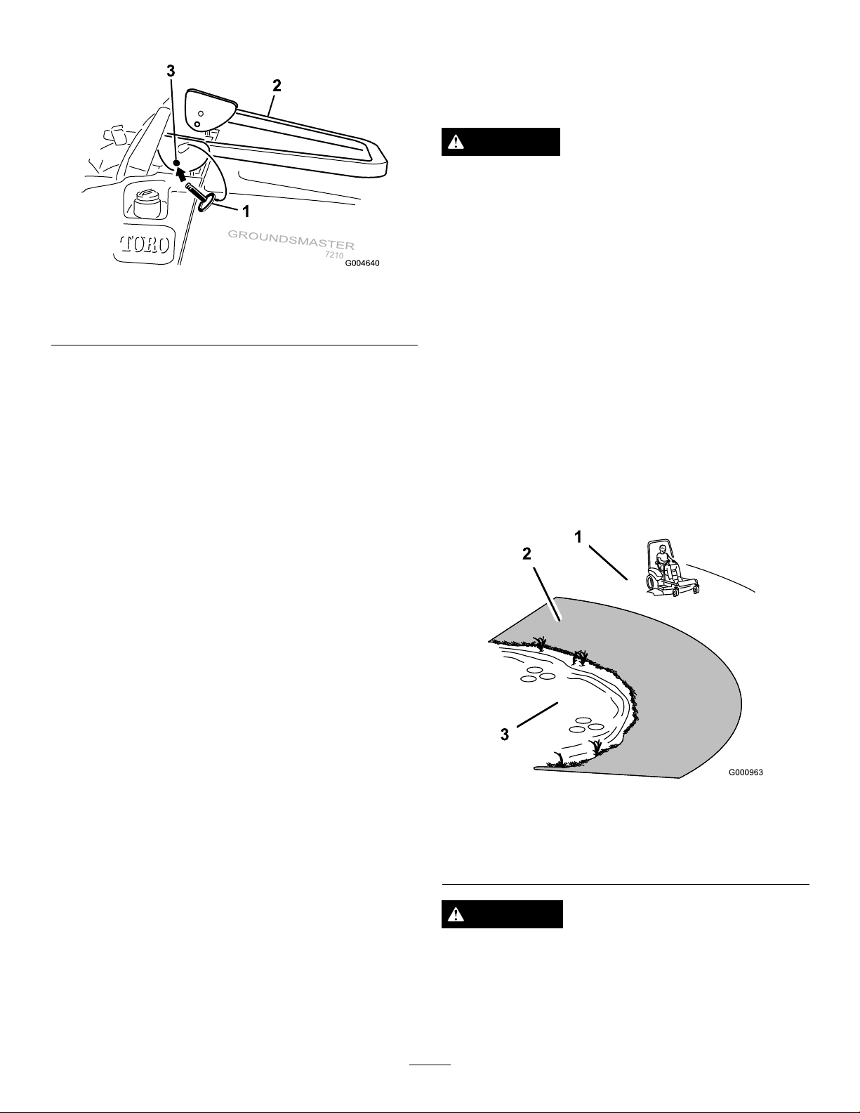
2.Lowertherollbartothedownposition(Figure43).
ThinkSafetyFirst
Pleasereadallsafetyinstructionsandsymbolsinthesafety
section.Knowingthisinformationcouldhelpyouor
bystandersavoidinjury.
DANGER
Operatingonwetgrassorsteepslopescancause
slidingandlossofcontrol.
Wheelsdroppingoveredgescancauserollovers,
whichmayresultinseriousinjury,deathor
drowning.
Figure43
1.Pin3.Mountinghole
2.Rollbar
3.Installthe2pinsandsecurethemwiththehairpin
cotterpins(Figure42).
Important:Ensurethattherearpartoftheseatis
securedwiththeseatlatch.
4.Toraisetherollbar,removethehairpincotterpinsand
removethe2pins(Figure42).
5.Raisetherollbartotheuprightpositionandinstallthe
twopinsandsecurethemwiththehairpincotterpins
(Figure42).
Important:Alwaysusetheseatbeltwhentherollbar
isintheraisedandlockedposition.Donotusetheseat
beltwhentherollbarisintheloweredposition.
Thereisnorolloverprotectionwhentherollbaris
down.
Alwayskeeptherollbarintheraisedandlocked
positionandusetheseatbelt.
Readandfollowtherolloverprotectioninstructions
andwarnings.
Toavoidlossofcontrolandpossibilityofrollover:
•Donotoperateneardrop-offsornearwater.
•Reducespeedanduseextremecautionon
slopes.
•Avoidsuddenturnsorrapidspeedchanges.
Figure44
1.SafeZone
2.Usewalkbehindmower
and/orhandtrimmernear
drop-offsandwater.
3.Water
CAUTION
Thismachineproducessoundlevelsinexcessof
85dBAattheoperatorsearandcancausehearing
lossthroughextendedperiodsofexposure.
Wearhearingprotectionwhenoperatingthis
machine.
31
Page 32
Theuseofprotectiveequipmentforeyes,ears,feetandhead
G020868
1
G020869
1
isrecommended.
OperatingtheParkingBrake
Alwayssettheparkingbrakewhenyoustopthemachineor
leaveitunattended.
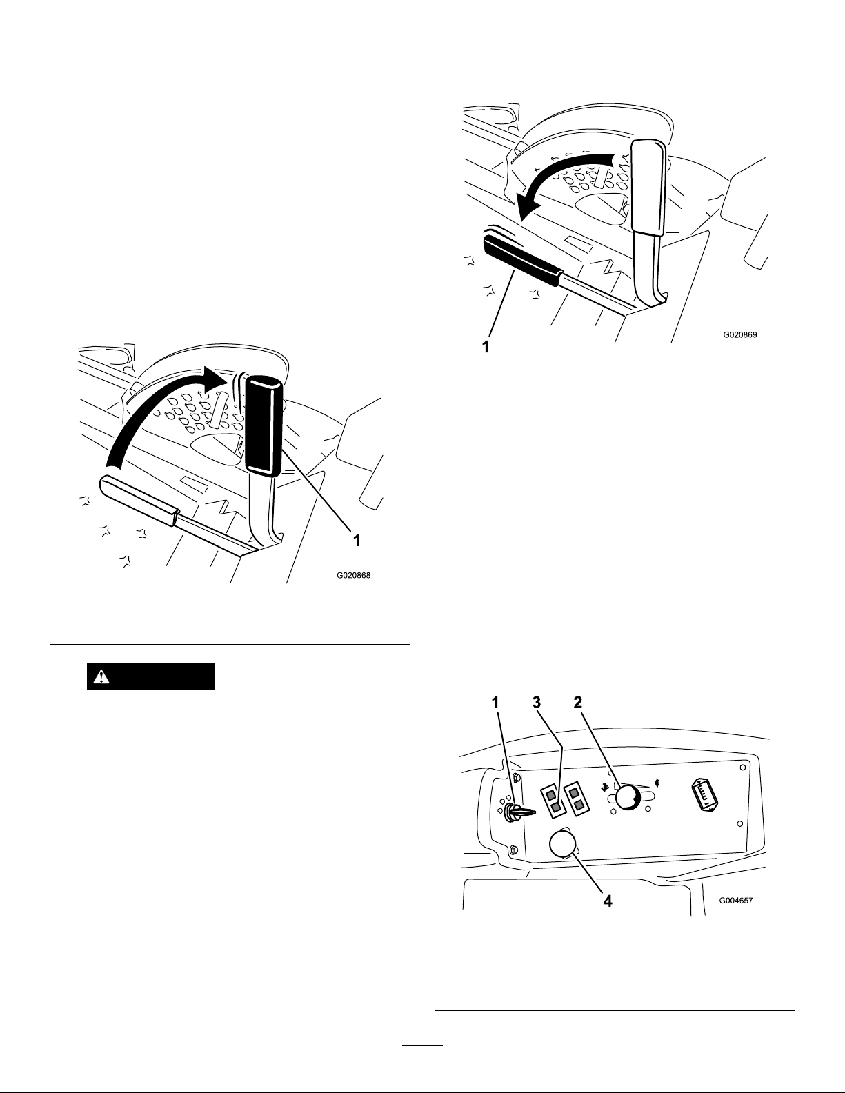
SettingtheParkingBrake
1.Movethemotioncontrollevers(Figure49)outtothe
neutrallockedposition.
2.Pullupandbackontheparkingbrakelevertosetthe
parkingbrake(Figure45).
Note:Theparking-brakelevershouldstayrmlyin
theengagedposition.
ReleasingtheParkingBrake
Pushforwardanddownontheparkingbrakelevertorelease
theparkingbrake(Figure46).
Figure46
1.Parking-brakelever
Figure45
1.Parking-brakelever
WARNING
Theparkingbrakemaynotholdthemachine
parkedonaslopeandcouldcausepersonal
injuryorpropertydamage.
Donotparkthemachineonslopesunlessthe
wheelsarechockedorblocked.
StartingandStoppingthe Engine
StartingtheEngine
1.Raisetherollbarupandlockitintoplace,sitonthe
seat,andfastentheseatbelt.
2.Ensurethatthemotioncontrolsareintheneutral
lockedposition.
3.Settheparkingbrake;referto
Brake(page32).
4.MovethePTO(powertake-off)switchtotheoff
position(Figure47).
SettingtheParking
Figure47
1.Ignitionswitch
2.Throttlecontrol
32
3.Glowpluglight
4.Powertakeoffswitch
(PTO)
Page 33
5.MovethethrottlelevermidwaybetweentheFastand
Slowpositions(Figure47).
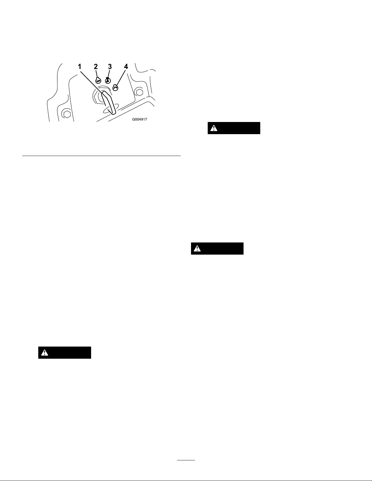
6.TurntheignitionkeyclockwisetotheRunposition
(Figure48).
Theglowpluglightwillturnonfor6seconds.
StoppingtheEngine
1.DisengagethePTO ,movethemotioncontrolleversto
theneutrallockedposition,settheparkingbrake,and
movethethrottlelevertotheSlowposition.
2.Lettheengineidlefor60seconds.
3.TurntheignitionkeytotheOffposition(Figure48).
Waitforallmovingpartstostopbeforeleavingthe
operatingposition.
4.Removethekeybeforetransportingorstoringmachine.
Important:Makesuretoremovethekeyasthe
fuelpumporaccessoriesmayrunandcausethe
batterytolosecharge.
Figure48
1.Ignitionswitch
2.Off4.Start
7.Aftertheglowplugindicatorlightgoesout,turnthe
keytotheStartposition.Whentheenginesstarts
releasethekey.
Important:Usestartingcyclesofnomorethan
15secondsperminutetoavoidoverheatingthe
startermotor.
Note:Additionalstartingcyclesmayberequired
whenstartingtheengineforthersttimeafterthefuel
systemhasbeencompletelydrained.
8.LeavethethrottlemidwaybetweentheSlowandFast
positionsuntiltheengineandhydraulicsystemwarm
up.
Important:Whentheengineisstartedfortherst
time,orafteranengineoilchange,oranoverhaul
oftheengine,transmission,orwheelmotor,
operatethemachinewiththethrottleleverinthe
Slowpositioninboththeforwardandreverse
directionsfor1to2minutes.Alsooperatethelift
leverandPTOlevertoensureproperoperation
ofallparts.Thenshuttheengineoffandcheck
uidlevels,checkforoilleaks,looseparts,and
anyothernoticeablemalfunctions.
3.Run/glowplug
CAUTION
Shuttheengineoffandwaitforallmoving
partstostopbeforecheckingforoilleaks,
looseparts,orothermalfunctions.
CAUTION
Childrenorbystandersmaybeinjuredifthey
moveorattempttooperatethetractorwhile
itisunattended.
Alwaysremovetheignitionkeyandsetthe
parkingbrakewhenleavingthemachine
unattended,evenifjustforafewminutes.
DrivingtheMachine
Thethrottlecontrolregulatestheenginespeedasmeasured
inrpm(revolutionsperminute).Placethethrottlecontrolin
theFastpositionforbestperformance.Alwaysoperateinthe
Fastthrottlepositionwhenmowing.
CAUTION
Themachinecanturnveryrapidly.Youmaylose
controlofitandcausepersonalinjuryordamage
tomachine.
•Usecautionwhenmakingturns.
•Slowthemachinedownbeforemakingsharp
turns.
1.Releasetheparkingbrake;refertoReleasingthe
ParkingBrake(page32).
Note:Theenginewillkillifthetractioncontrollevers
aremovedwiththeparkingbrakeengaged.
2.Movetheleverstothecenter,unlockedposition.
3.Drivethemachineasfollows:
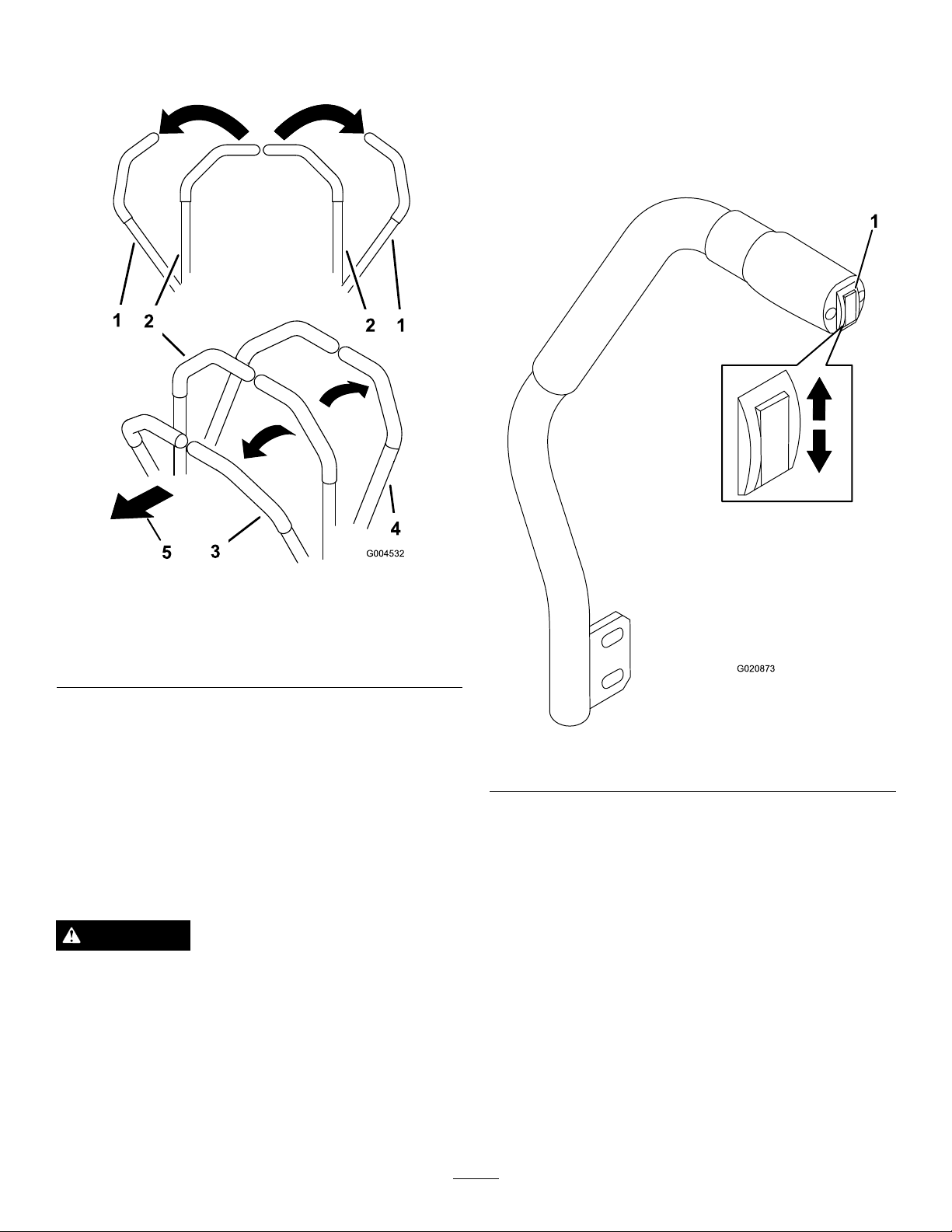
•Togostraightforward,slowlypushthemotion
controlleversforward(
•TogoStraightbackward,slowlypullthemotion
controlleversrearward(Figure49).
•Toturn,slowthemachinebypullingbackonboth
leversandthenpushforwardontheleveronthe
oppositesidefromwhichyouwanttoturn(
49).
•Tostop,pullthemotioncontrolleverstothe
neutralposition.
Figure49).
Figure
33
Page 34
Note:Thefartheryoumovethetractioncontrol
1
G020873
leversineitherdirection,thefasterthemachinewill
moveinthatdirection.
OperatingtheMower
RaisingandLoweringtheMowerwith
theDeckLiftSwitch
Thedeck-liftswitchraisesandlowersthemowerdeck(Figure
50).Theenginemustberunningforyoutousethislever.
Figure49
1.Motioncontrol
lever-neutrallocked
position
2.Centerunlockposition
StoppingtheMachine
Tostopthemachine,movethetraction-controlleversto
neutralandtothelockedposition,disengagethepowertake
off(PTO),movethethrottletotheSlowposition,andstop
theengine.
Settheparkingbrakewhenyouleavethemachine;referto
SettingtheParkingBrake.Remembertoremovethekeyfrom
theignitionswitch.
3.Forward
4.Backward
CAUTION
Childrenorbystandersmaybeinjuredifthey
attempttomoveoroperatethetractorwhileitis
unattended.
Figure50
1.Deck-liftswitch
•Tolowerthemowerdeck,pushthedeck-liftswitchdown
(Figure50).
Important:Whenthemowerdeckislowered,itwill
besetinaoat/idleposition.
•Toraisethemoverdeck,pushthedeck-liftswitchup
(Figure50).
Important:Donotcontinuetoholdtheswitchupor
downafterthemowerhasfullyraisedorlowered.Doing
sowilldamagethehydraulicsystem.
Alwaysremovetheignitionkeyandsettheparking
brakewhenleavingthemachineunattended,even
ifjustforafewminutes.
34
Page 35
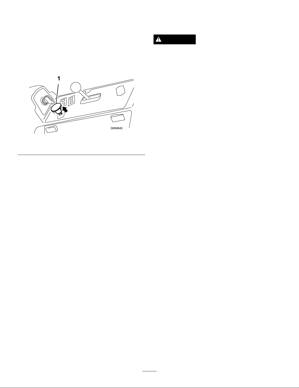
EngagingthePowerTakeOff(PTO)
UsingtheSafetyInterlock
Thepowertakeoff(PTO)switchstartsandstopsthemower
bladesandsomepoweredattachments.
1.Iftheengineiscold,allowtheenginetowarmup5to
10minutesbeforeengagingthePTO .
2.Whileseatedintheseat,releasethepressureonthe
tractioncontrolleversandplacetheminneutral.
3.PulluponthePTOswitchtoengageit(
Figure51
1.PTOswitch
Figure51).
DisengagingthePTO
Todisengage,pushthePTOswitchtotheoffposition.
System
CAUTION
Ifthesafetyinterlockswitchesaredisconnectedor
damagedthemachinecouldoperateunexpectedly
causingpersonalinjury.
•Donottamperwiththeinterlockswitches.
•Checktheoperationoftheinterlockswitches
dailyandreplaceanydamagedswitchesbefore
operatingthemachine.
UnderstandingtheSafetyInterlock
System
Thesafetyinterlocksystemisdesignedtopreventtheengine
fromstartingunless:
•Youaresittingontheseatortheparkingbrakeisengaged.
•Thepowertake-off(PTO)isdisengaged.
•Themotion-controlleversareintheneutrallocked
position
•Theenginetemperatureisbelowthemaximumoperating
temperature.
Thesafetyinterlocksystemalsoisdesignedtostoptheengine
whenthetractioncontrolsaremovedfromtheneutrallocked
positionwiththeparkingbrakeengaged.Ifyourisefromthe
seatwhenthePTOisengagedthereisa1-seconddelayand
thentheenginestops.
35
Page 36

TestingtheSafetyInterlockSystem
ServiceInterval:Beforeeachuseordaily
Testthesafetyinterlocksystembeforeyouusethemachine
eachtime.Ifthesafetysystemdoesnotoperateasdescribed
below,haveanAuthorizedServiceDealerrepairthesafety
systemimmediately.
1.Sittingontheseat,engagetheparkingbrakeandmove
thePTOtoon.Trystartingtheengine;theengine
shouldnotcrank.
2.Sittingontheseat,engagetheparkingbrakeandmove
thePTOtooff.Moveeithermotioncontrollever(out
ofneutrallockedposition).Trystartingtheengine;the
engineshouldnotcrank.Repeatforothercontrollever.
3.Sittingontheseat,engagetheparkingbrake,movethe
PTOswitchtooffandmovethemotioncontrollevers
totheneutrallockedposition.Nowstarttheengine.
Whiletheengineisrunning,releasetheparkingbrake,
engagethePTOandriseslightlyfromtheseat;the
engineshouldstopwithin2seconds.
4.Withoutanoperatorontheseat,engagetheparking
brake,movethePTOswitchtooffandmovethe
motioncontrolleverstotheneutrallockedposition.
Nowstarttheengine.Whiletheengineisrunning,
centereithermotioncontrol;theengineshouldstop
within2seconds.Repeatfortheothermotioncontrol.
5.Withoutanoperatorontheseat,disengagetheparking
brake,movethePTOswitchtooff,andmovethe
motioncontrolleverstotheneutrallockedposition.
Trystartingtheengine;theengineshouldnotcrank.
36
Page 37
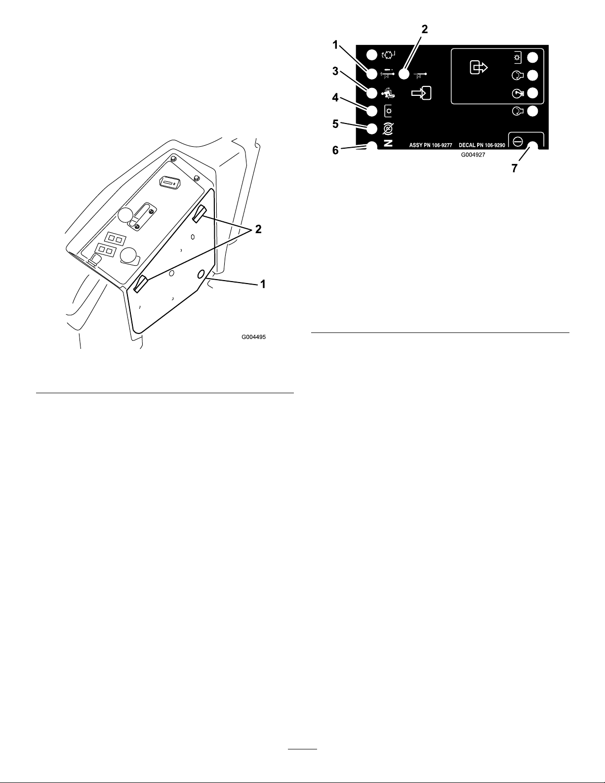
UsingtheSCMtoDiagnoseSystem
Problems
Themachineisequippedwithastandardcontrolmodule
(SCM)monitoringsystemthattracksthefunctionofvarious
keysystems.TheSCMislocatedundertherightcontrol
panel.Accessitthroughthesidepanelcover(Figure52).
Toopenthesidepanelcover,releasethe2latchesandpull
outonit.
Figure53
1.Hightemperatureshutdown—theenginetemperaturehas
exceededsafelevelsandtheenginehasbeenshutdown.
Checkthecoolingsystem.
2.Hightemperaturewarning—theenginetemperatureis
approachingunsafelevelsandthemowerdeckhasbeen
shutdown.Checkthecoolingsystem.
3.Operatorisintheseat
4.ThePTOisOn
5.Theparkingbrakeisnotengaged
6.ControlsareinNeutral
7.TheSCMisreceivingpowerandisoperational
Figure52
1.Sidepanelcover
2.Latches
OnthefaceoftheSCMare11LEDsthatilluminateto
indicatevarioussystemconditions.Sevenoftheselightscan
beusedbytheoperatorforsystemdiagnosis.RefertoFigure
53foradescriptionofwhateachlightmeans.Fordetails
onusingtherestoftheSCMfunctions,refertotheService
Manual,availablethroughyourAuthorizedToroDistributor.
37
Page 38
PositioningtheSeat
G020871
1
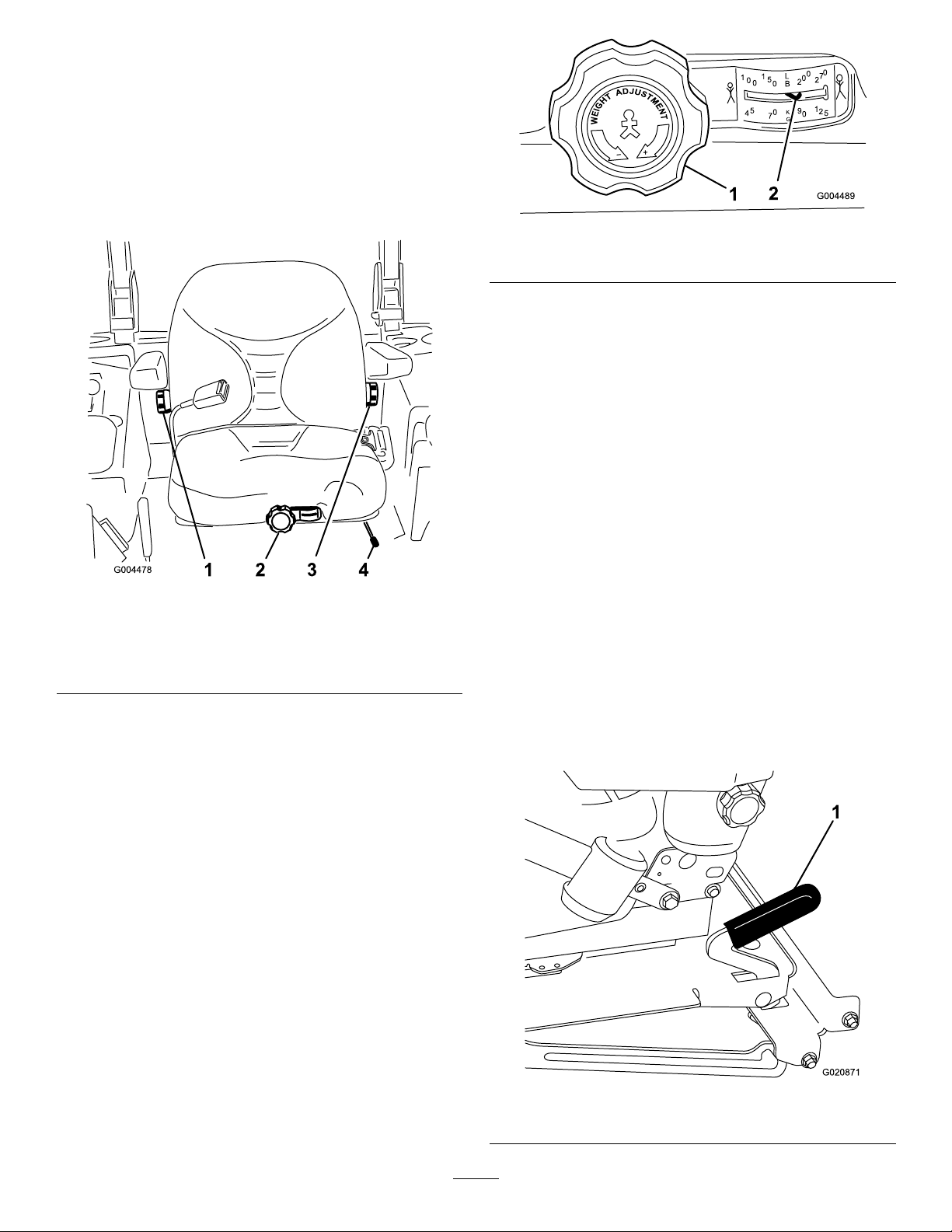
ChangingtheSeatPosition
Theseatcanmoveforwardandbackward.Positiontheseat
whereyouhavethebestcontrolofthemachineandaremost
comfortable.
1.Toadjust,movetheleversidewaystounlocktheseat
(Figure54).
Figure55
1.Seatsuspensionknob2.Operatorweightsetting
ChangingtheBackPosition
Thebackoftheseatcanbeadjustedtoprovideacomfortable
ride.Positionthebackoftheseatwhereitismost
comfortable.
Toadjustit,turntheknob,undertheright-sidearmrest,in
eitherdirectiontoprovidethebestcomfort(Figure54).
ChangingtheLumbarSupport
Thebackoftheseatcanbeadjustedtoprovideacustomized
lumbarsupportforyourlowerback.
Figure54
1.Backrestknob3.Lumbarsupport
2.Seatsuspensionknob4.Seatpositionadjustment
2.Slidetheseattothedesiredpositionandreleaselever
tolockinposition.
3.Verifythattheseathaslockedintoplacebyattempting
tomoveitbackandforth.
adjustmentknob
lever
ChangingtheSeatSuspension
Theseatcanbeadjustedtoprovideasmoothandcomfortable
ride.Positiontheseatwhereyouaremostcomfortable.
Withoutsittingontheseat,turntheknobinfronteither
directiontoprovidethebestcomfort(
Figure54).
Toadjustit,turntheknob,undertheleft-sidearmrest,in
eitherdirectiontoprovidethebestcomfort(Figure54).
UnlatchingtheSeat
Toaccessthehydraulicandothersystemsundertheseat,
unlatchtheseatandswingitforward.
1.Usetheseatpositionadjustmentlevertoslidetheseat
allthewayforward.
2.Pulltheseatlatchforwardandliftuptounlatchthe
Figure56).
seat(
Figure56
1.Seatlatch
38
Page 39
PushingtheMachinebyHand
LoadingMachines
Important:Nevertowthemachinebecausehydraulic
damagemayoccur.
PushingtheMachine
1.Disengagethepowertake-off(PTO)andturnthe
ignitionkeytooff.Movetheleverstotheneutral
lockedpositionandapplytheparkingbrake.Remove
thekey.
2.Lifttheseat.
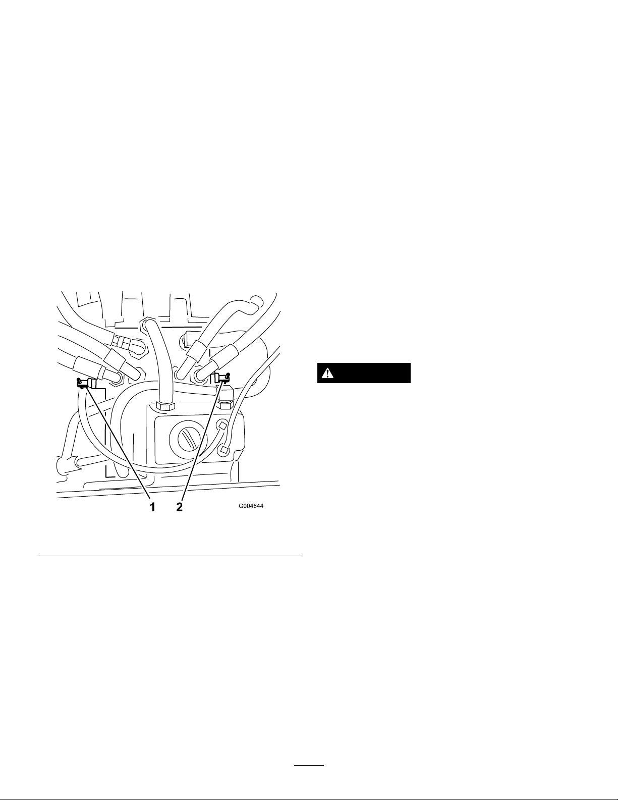
3.Rotateeachby-passvalvecounterclockwise1turn
(Figure57).
Thisallowshydraulicuidtoby-passthepump
enablingthewheelstoturn.
Important:Donotrotatetheby-passvalvesmore
than1turn.Thispreventsvalvesfromcomingout
ofthebodyandcausinguidtorunout.
Useextremecautionwhenloadingunitsontrailersortrucks.
Onefull-widthrampthatiswideenoughtoextendbeyond
thereartiresisrecommendedinsteadofindividualrampsfor
eachsideoftheunit(Figure58).Thelowerrearsectionof
thetractorframeextendsbackbetweentherearwheelsand
servesasastopfortippingbackward.Havingafull-width
rampprovidesasurfacefortheframememberstocontactif
theunitstartstotipbackward.Ifitisnotpossibletouseone
full-widthramp,useenoughindividualrampstosimulatea
full-widthcontinuousramp.
Therampshouldbelongenoughsothattheanglesdonot
exceed15degrees(
mowercomponentstogetcaughtastheunitmovesfrom
ramptotrailerortruck.Steeperanglesmayalsocausethe
unittotipbackward.Ifloadingonornearaslope,position
thetrailerortrucksoitisonthedownsideoftheslopeand
therampextendsuptheslope.Thiswillminimizetheramp
angle.Thetrailerortruckshouldbeaslevelaspossible.
Important:Donotattempttoturntheunitwhileonthe
ramp;youmaylosecontrolanddriveofftheside.
Avoidsuddenaccelerationwhendrivinguparampand
suddendecelerationwhenbackingdownaramp.Both
maneuverscancausetheunittotipbackward.
Figure58).Asteeperanglemaycause
Figure57
1.Rightby-passvalve
4.Disengagetheparkingbrakebeforepushing.
2.Leftby-passvalve
ChangingtoMachineOperation
Rotateeachby-passvalveclockwise1turnandhandtighten
them(torqueofapproximately71in-lb(8N-m)(Figure57).
Note:Donotovertightentheby-passvalves.
WARNING
Loadingaunitontoatrailerortruckincreasesthe
possibilityofbackwardtip-overandcouldcause
seriousinjuryordeath.
•Useextremecautionwhenoperatingauniton
aramp.
•Useonlyasingle,full-widthramp;Donotuse
individualrampsforeachsideoftheunit.
•Ifindividualrampsmustbeused,useenough
rampstocreateanunbrokenrampsurfacewider
thantheunit.
•Donotexceeda15degreeanglebetweenramp
andgroundorbetweenrampandtrailerortruck.
•Avoidsuddenaccelerationwhiledrivingunitup
aramptoavoidtippingbackward.
•Avoidsuddendecelerationwhilebackingunit
downaramptoavoidtippingbackward.
Themachinewillnotdriveunlesstheby-passvalvesare
turnedinward.
39
Page 40
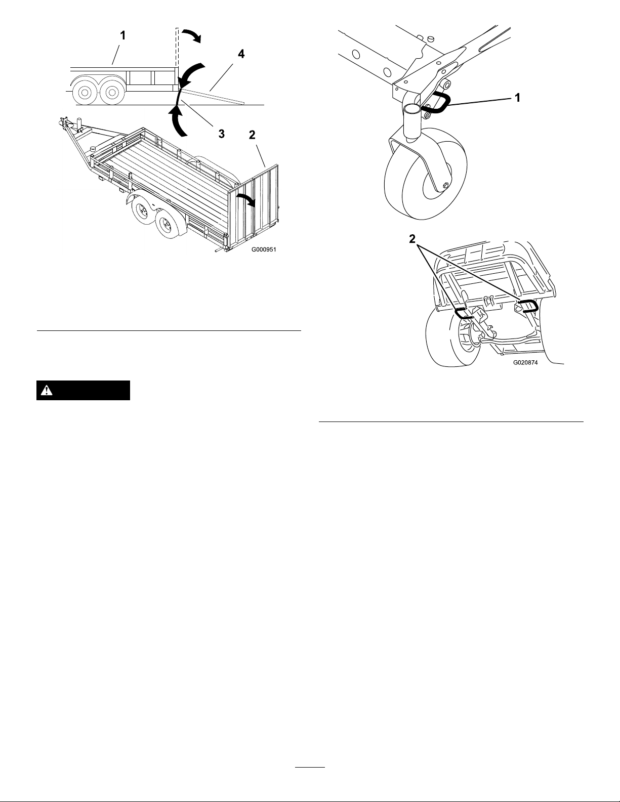
Figure58
1
G020874
1.Trailer3.Notgreaterthan
2.Full-widthramp4.Full-widthramp—side
15degrees
view
TransportingtheMachine
WARNING
Drivingonthestreetorroadwaywithoutturn
signals,lights,reectivemarkings,oraslow
movingvehicleemblemisdangerousandcanlead
toaccidentscausingpersonalinjury.
Donotdrivethemachineonapublicstreetor
roadwaywithoutsigns,lights,and/ormarkings
requiredbylocalregulations.
Useaheavy-dutytrailerortrucktotransportthemachine.
Ensurethatthetrailerortruckhasallnecessarylightingand
markingasrequiredbylaw.Pleasecarefullyreadallthesafety
instructions.Knowingthisinformationcouldhelpyouor
bystandersavoidinjury.
1.Fronttie-down(leftside
shown)
Figure59
2.Reartie-downs
Totransportthemachine:
•Ensurethatyourvehicle,hitch,safetychains,andtrailer
areadequatefortheloadyouarepullingandthatthey
meetalllocaltrafcregulationsforyourarea.
•Lockthebrakeandblockthewheels.
•Securelyfastenthemachinetothetrailerortruckwith
straps,chains,cable,orropesasrequiredbylocaltrafc
regulationsinyourarea(
Figure59).
40
Page 41

Maintenance
Note:Determinetheleftandrightsidesofthemachinefromthenormaloperatingposition.
RecommendedMaintenanceSchedule(s)
MaintenanceService
Interval
Aftertherst10hours
Aftertherst50hours
Aftertherst200hours
Beforeeachuseordaily
Every50hours
Every100hours
Every150hours
Every200hours
MaintenanceProcedure
•Torquetheframemountingbolts.
•Torquewheellugnuts.
•Changethemowerdeckgearboxlubricant.
•Changetheengineoilandlter.
•Changethehydraulicoilandlter.
•Testthesafetysystem.
•Checktheengineoillevel.
•Checktheenginecoolantlevel.
•Cleantheradiatorwithcompressedair(donotusewater).
•Checkthehydraulicuidlevel.
•Cleanthemowerdeck.
•Greasethebearingandbushinggreasettings.
•Checkbatterycableconnections.
•Checkthetirepressure.
•Checktheconditionofthebladedrivebeltsonthemowerdeck.
•Checkthealternatorbelttension.
•Checkthelubricantinthemowerdeckgearbox.
•Changetheengineoilandlter.
•Inspectcoolingsystemhosesandseals.Replacethemifcrackedortorn.
•Torquewheellugnuts.
•Changethemowerdeckgearboxlubricant.
•Servicetheaircleaner.
Every400hours
Every800hours
Every1,500hours
Every2years
Important:Refertoyour
•Replacethefuelltercanisterforthewaterseparator.
•Drainwaterorothercontaminantsfromthewaterseparator.
•Checkthefuellinesandconnections.
•Changethehydraulicoilandlter.
•Inspectenginevalveclearance.RefertoyourEngineOperator'sManual.
•Replacemovinghoses.
•Drainandcleanthefueltank.
•Flushandreplacecoolingsystemuid.
Engine Operator's Man ual
foradditionalmaintenanceprocedures.AdetailedService
ManualisalsoavailableforpurchasefromyourAuthorizedToroDistributor.
41
Page 42
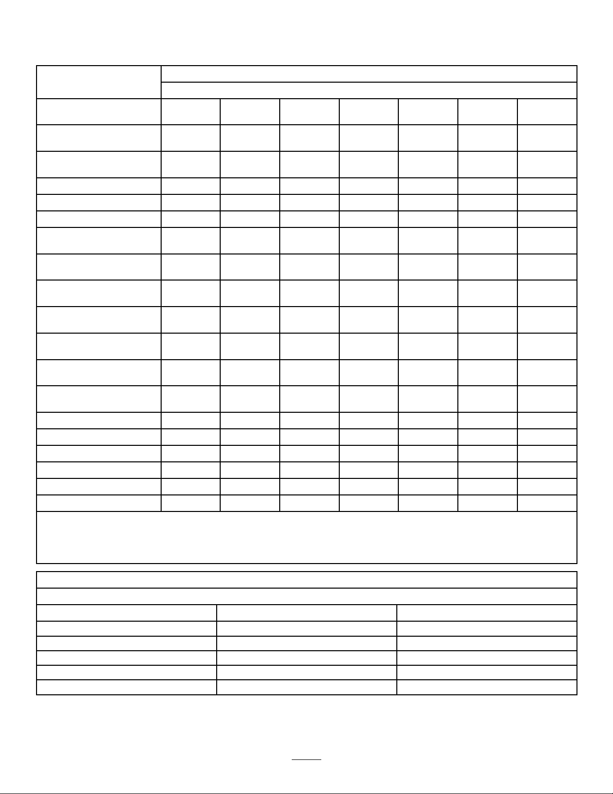
DailyMaintenanceChecklist
Duplicatethispageforroutineuse.
Fortheweekof: MaintenanceCheckItem
Mon.Tues.Wed.Thurs.Fri.
CheckSafetyInterlock
Operation
CheckGrassDeectorin
DownPosition(ifapplicable)
CheckParkingBrake
Operation
CheckFuelLevel
CheckHydraulicOilLevel
CheckEngineOilLevel
CheckCoolingSystemFluid
Level
CheckDrainWater/Fuel
Separator
CheckAirFilterRestriction
Indicator
CheckRadiator&Screenfor
Debris
CheckUnusualEngine
Noises
CheckUnusualOperating
Noises
CheckHydraulicHosesfor
Damage
CheckFluidLeaks
CheckTirePressure
CheckInstrumentOperation
CheckConditionofBlades
LubricateAllGreaseFittings
Touch-upDamagedPaint
1.Checkglowplugandinjectornozzles,ifhardstarting,excesssmokeorroughrunningisnoted.
3
1
2
Sat.Sun.
2.Immediatelyaftereverywashing,regardlessoftheintervallisted.
3.Ifindicatorshowsred
NotationforAreasofConcern
Inspectionperformedby:
ItemDate
Information
42
Page 43
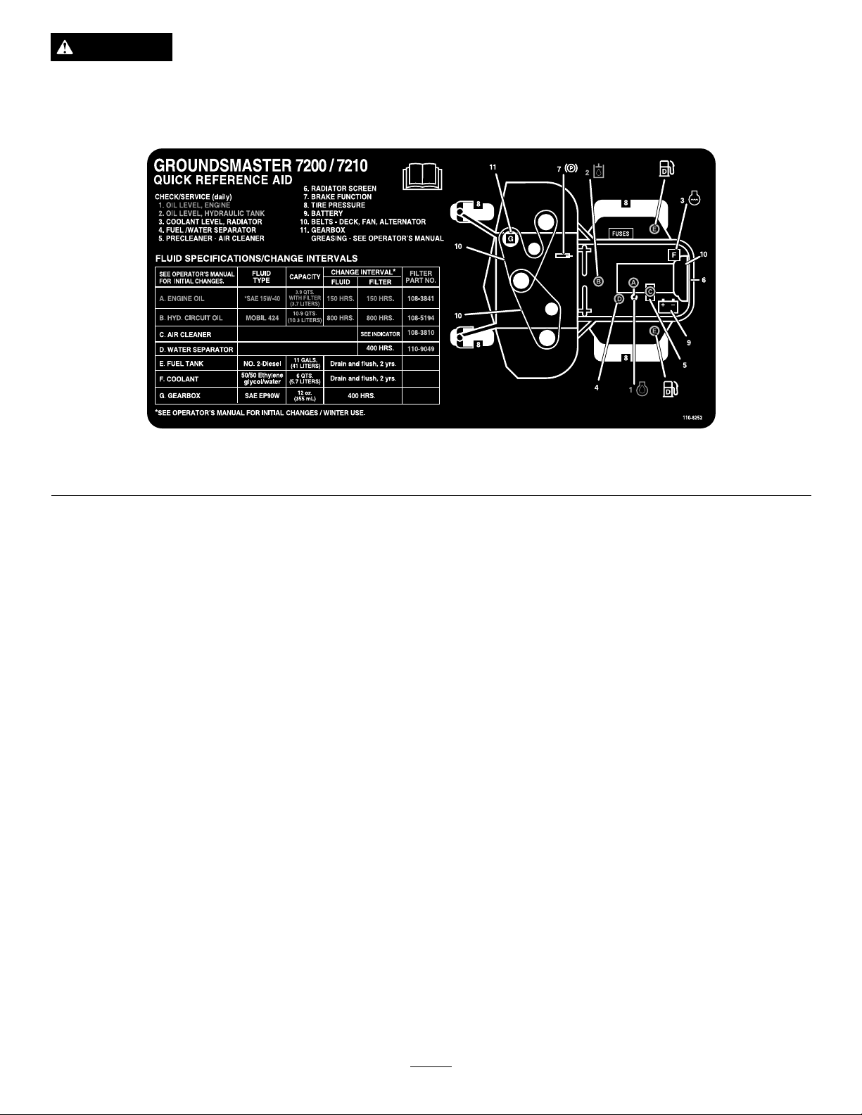
CAUTION
Ifyouleavethekeyintheignitionswitch,someonecouldaccidentlystarttheengineandseriouslyinjure
youorotherbystanders.
Removethekeyfromtheignitionbeforeyoudoanymaintenance.
Figure60
ServiceIntervalChart
Premaintenance
Procedures
Important:Thefastenersonthecoversofthismachine
aredesignedtoremainonthecoverafterremoval.
Loosenallofthefastenersoneachcoverafewturnsso
thatthecoverisloosebutstillattached,thengoback
andloosenthemuntilthecovercomesfree.Thiswill
preventyoufromaccidentallystrippingtheboltsfree
oftheretainers.
Lubrication
GreasingtheBearingsand Bushings
ServiceInterval:Every50hours
Themachinehasgreasettingsthatmustbelubricated
regularlywithNo.2general-purpose,lithium-basedgrease.If
themachineisoperatedundernormalconditions,lubricate
allbearingsandbushingsafterevery50hoursofoperation.
Lubricatingbearingsandbushingsdailywhenoperating
conditionsareextremelydustyanddirty.Dustyanddirty
operatingconditionscouldcausedirttogetintothebearings
andbushings,resultinginacceleratedwear.Lubricatethe
greasettingsimmediatelyaftereverywashing,regardlessof
intervalspecied.
1.Wipethegreasettingscleansothatforeignmatter
cannotbeforcedintothebearingorbushing.
2.Pumpgreaseintothettings.
3.Wipeoffexcessgrease.
Figure61andFigure62illustratethelocationsofthegrease
ttings.
Important:Thettingsontheaxlesofthecasterwheels
arenotillustrated.Ensurethatyougreasethesettings
aswell.
43
Page 44
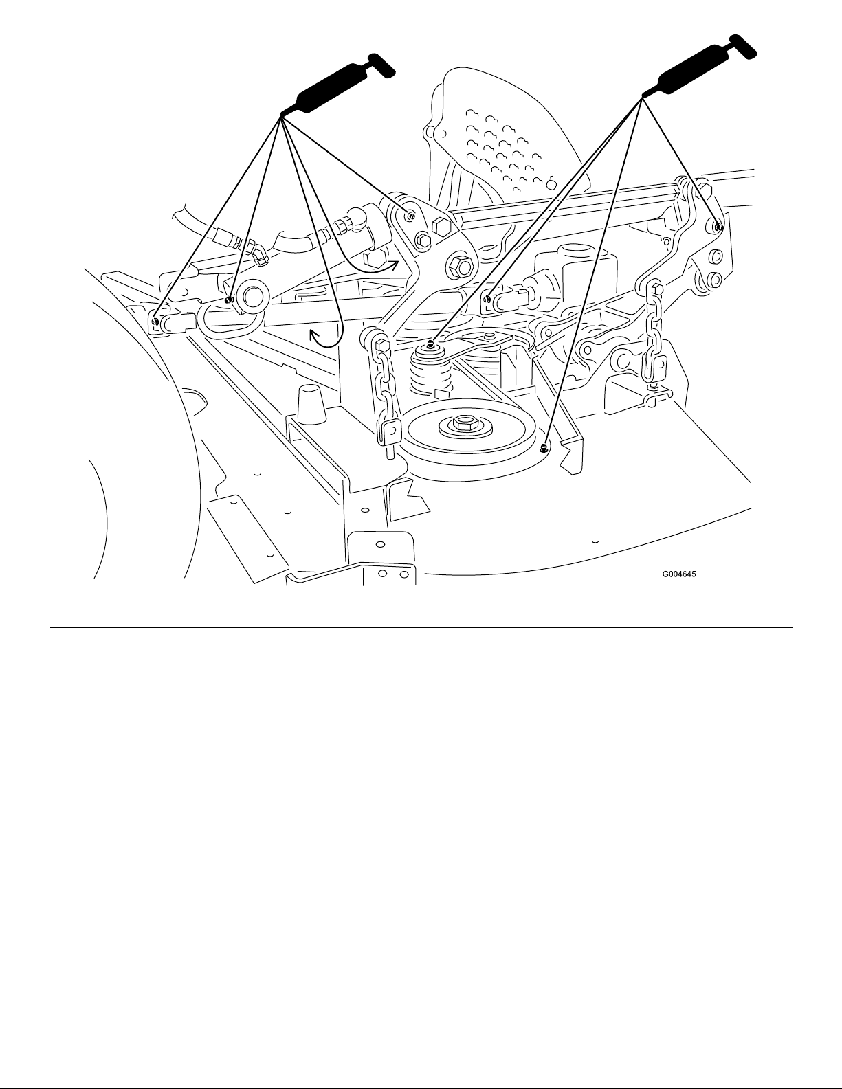
Figure61
44
Page 45
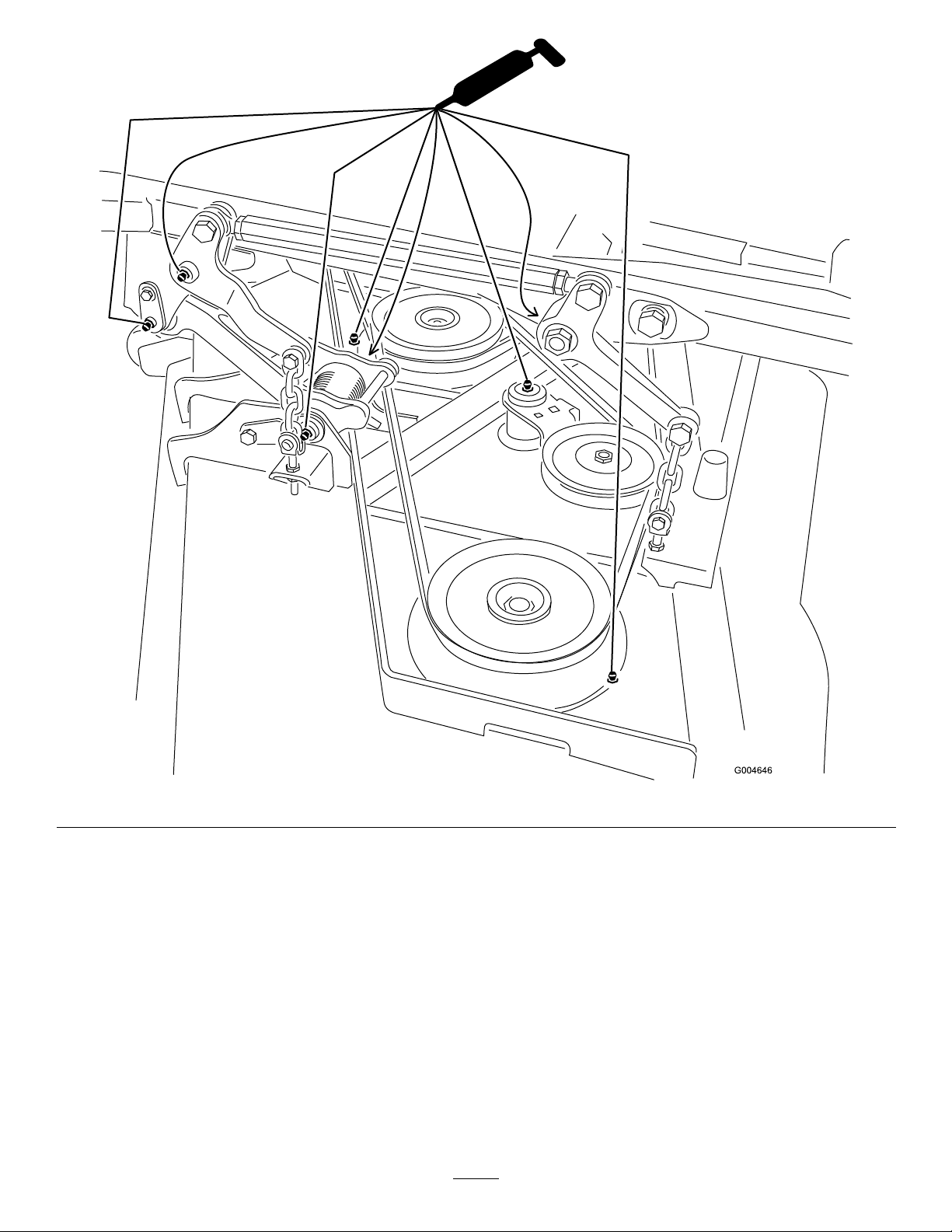
Figure62
Note:Bearinglifecanbenegativelyaffectedbyimproper
washdownprocedures.Donotwashdowntheunitwhenit
isstillhotandavoiddirectinghigh-pressureorhighvolume
sprayatthebearingsorseals.
ServicingtheMowerDeck GearBoxLubricant
ThegearboxisdesignedtooperatewithSAE80-90gear
lube.Althoughthegearboxcomesfromthefactorywith
lubricant,checkthelevelofthelubricantinthecutting
unitbeforeoperatingitandasrecommendedintheDaily
MaintenanceChecklist(page42)
.
CheckingtheMowerDeckGearBox
Lubricant
ServiceInterval:Every150hours
1.Positionthemachineandcuttingunitonalevelsurface.
2.Lowerthemowerdecktothe2.5cm(1inch)height
ofcut.
3.DisengagethePTO ,movethemotioncontrolleversto
theneutrallockedposition,andsettheparkingbrake.
4.MovethethrottlelevertotheSlowposition,stopthe
engine,removethekey,andwaitforallmovingpartsto
stopbeforeleavingtheoperatingposition.
5.Liftthefootrest,exposingthetopofthemowerdeck.
45
Page 46
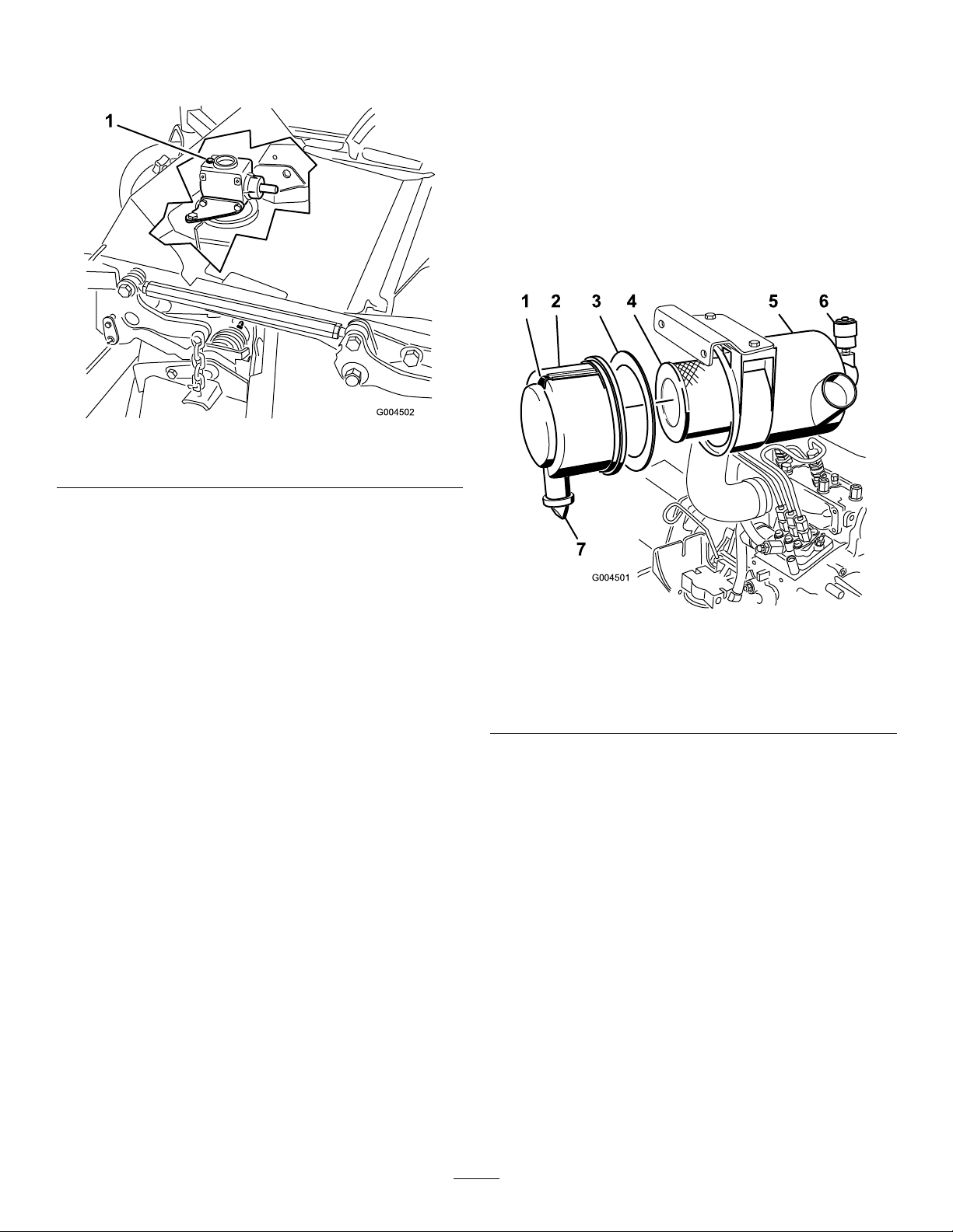
6.Removethedipstick/llplugfromthetopofthegear
G004501
123456
7
box(Figure63)andmakesurethatthelubricantis
betweenthemarksonthedipstick.
Figure63
1.Fillpluganddipstick
EngineMaintenance
CheckingtheAirCleaner
1.Checktheaircleanerbodyfordamage,whichcould
possiblycauseanairleak.Replaceadamagedair
cleanerbody.Checkthewholecleanairintakesystem
forleaks,damage,orloosehoseclamps.
2.Servicetheaircleanerlterwhentheaircleaner
indicator(
hours(morefrequentlyinextremelydustyordirty
conditions).Donotoverservicetheairlter.
Figure64)showsredorevery400
7.Ifthelubricantlevelislow,addenoughlubricantuntil
thelevelisbetweenthemarksonthedipstick.
Note:Donotoverllgearbox;overllingthegear
boxmaydamageit.
ChangingtheMowerDeckGearBox
Lubricant
ServiceInterval:Aftertherst50hours
Every400hours
1.Positionthemachineandcuttingunitonalevelsurface.
2.Lowerthemowerdecktothe2.5cm(1inch)height
ofcut.
3.DisengagethePTO ,movethemotioncontrolleversto
theneutrallockedposition,andsettheparkingbrake.
4.MovethethrottlelevertotheSlowposition,stopthe
engine,removethekey,andwaitforallmovingpartsto
stopbeforeleavingtheoperatingposition.
5.Liftthefootrest,exposingthetopofthemowerdeck.
6.Removethedipstick/llplugfromthetopofthegear
Figure63).
box(
7.Placeafunnelanddrainpanunderthedrainplug
locatedunderthefrontofthegearboxandremovethe
plug,drainingthelubricantintothepan.
8.Replacethedrainplug.
9.Addenoughlubricant,approximately283ml(12oz),
untilthelevelisbetweenthemarksonthedipstick.
Note:Donotoverllgearbox;overllingthegear
boxmaydamageit.
Figure64
1.Aircleanercover5.Aircleanerindicator
2.Gasket
3.Filter7.Rubberoutletvalve
4.Aircleanerbody
3.Besurethecoverisseatedcorrectlyandsealswiththe
aircleanerbody.
6.Aircleanerlatch
ServicingtheAirCleaner
ServiceInterval:Every400hours
1.Pullthelatchoutwardandrotatetheair-cleanercover
counter-clockwise(
2.Removethecoverfromtheair-cleanerbody(
64
).
3.Beforeremovingthelter,uselowpressureair(40psi,
cleananddry)tohelpremovelargeaccumulationsof
debrispackedbetweenoutsideofprimarylterand
thecanister.
Thiscleaningprocesspreventsdebrisfrommigrating
intotheintakewhentheprimarylterisremoved.
Important:Avoidusinghigh-pressureairwhich
couldforcedirtthroughthelterintotheintake
tract.
Figure64).
Figure
46
Page 47
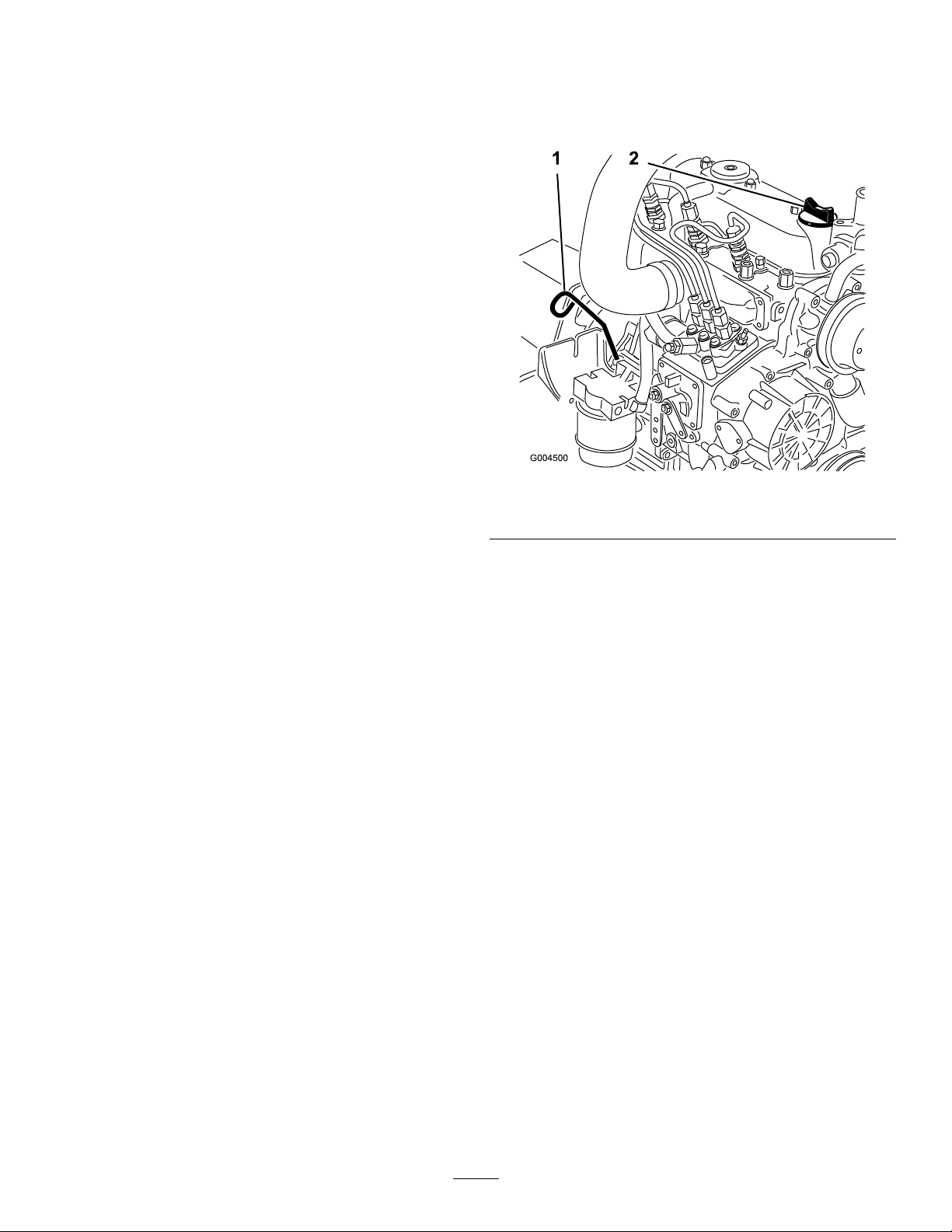
4.Removeandreplacetheprimarylter(Figure64).
Important:Donotcleantheusedelementto
avoiddamagetotheltermedia.
5.Inspectthenewlterforshippingdamage,checking
thesealingendofthelterandthebody.
Important:Donotuseadamagedelement.
6.Ensurethatthefoamgasketisinplaceinthecoverand
thatitisnottornordamaged(Figure64).
Note:Ifitisdamaged,replaceit.
7.Insertthenewlterbyapplyingpressuretotheouter
rimoftheelementtoseatitinthecanister.
Important:Donotapplypressuretotheexible
centerofthelter.
8.Cleanthedirtejectionport(locatedintheremovable
cover)asfollows:
A.Removetherubberoutletvalvefromthecover
(Figure64).
B.Cleanthecavity.
C.Replacetheoutletvalve.
9.Installthecoverorientingtherubberoutletvalveina
downwardposition—betweenapproximately5:00to
7:00whenviewedfromtheend.
10.Resettheindicator(
Figure64)ifshowingred.
3.Removethedipstick(
installthedipstick.Removethedipstickandcheckthe
oillevel.
TheoillevelshouldbeuptotheFullmarkonthe
dipstick.
1.Dipstick
4.IftheoillevelisbelowtheFullmark,removethell
Figure65)andaddoiluntilthelevelreachesthe
cap(
Fullmarkonthedipstick.
Figure65),wipeitclean,and
Figure65
2.Oilll
ServicingtheEngineOil
CheckingtheEngineOilLevel
ServiceInterval:Beforeeachuseordaily
Theengineisshippedwithoilinthecrankcase;however,the
oillevelmustbecheckedbeforeandaftertheengineisrst
started.Checkoillevelbeforeeachday'soperationoreach
timeyouusethemachine.
Thecrankcasecapacityisapproximately4qt(3.8L)withthe
lter.Usehigh-qualityengineoilthatmeetsthefollowing
specications:
•APIClassicationLevelRequired:CH-4,CI-4orhigher.
•Preferredoil:SAE15W-40(above0°F(-17°C)
•Alternateoil:SAE10W-30or5W-30(alltemperatures)
Note:T oroPremiumEngineoilisavailablefromyour
distributorineither15W-40or10W-30viscosity.Seethe
partscatalogforpartnumbers.
1.Parkthemachineonalevelsurface,lowerthemower
deck,movethethrottlelevertotheSlowposition,
stoptheengine,andremovethekeyfromtheignition
switch.
Important:Donotoverll.
Note:Useacleanfunneltopreventspills.
5.Installtheoilllcap.
6.Closethehood.
2.Openthehood.
47
Page 48
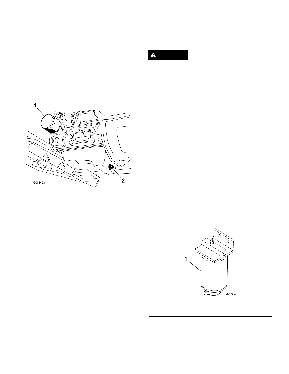
ChangingtheEngineOilAndFilter
ServiceInterval:Aftertherst50hours
Every150hours
Changetheoilandlterinitiallyafterrst50hoursof
operationandthenevery150hoursofoperationthereafter.If
possible,runtheenginejustbeforechangingtheoilbecause
warmoilowsbetterandcarriesmorecontaminantsthan
coldoil.
1.Positionthemachineonalevelsurface.
2.Openthehood.
3.Setadrainpanundertheoilpanandinlinewiththe
drainplug(
Figure66).
FuelSystem
Maintenance
Note:RefertoAddingFuel(page29)forproperfuel
recommendations.
DANGER
Undercertainconditions,dieselfuelandfuel
vaporsarehighlyammableandexplosive.Are
orexplosionfromfuelcanburnyouandothersand
cancausepropertydamage.
•Useafunnelandllthefueltankoutdoors,in
anopenarea,whentheengineisoffandiscold.
Wipeupanyfuelthatspills.
•Donotllthefueltankcompletelyfull.Addfuel
tothefueltankuntilthelevelistothebottom
ofthellerneck.
•Neversmokewhenhandlingfuel,andstayaway
fromanopenameorwherefuelfumesmaybe
ignitedbyaspark.
•Storefuelinaclean,safety-approvedcontainer
andkeepthecapinplace.
Figure66
1.Oillter
4.Cleantheareaaroundthedrainplug.
5.Removethedrainplugandallowtheoiltoowinto
drainpan.
6.Removeandreplacetheoillter(
7.Aftertheoilisdrained,installthedrainplugandwipe
upanyoilthatisspilled.
8.Fillthecrankcasewithoil;refertoCheckingtheEngine
OilLevel(page30).
2.Drainplug
Figure66).
ServicingtheWaterSeparator
ServiceInterval:Every400hours
Every400hours
Drainwaterorothercontaminantsfromwaterseparator
(
Figure67)daily.
1.Placeacleancontainerunderthefuellter.
2.Loosenthedrainplugonthebottomofthelter
canister.
Figure67
1.Waterseparatorltercanister
3.Cleantheareawheretheltercanistermounts.
4.Removetheltercanisterandcleanthemounting
surface.
5.Lubricatethegasketontheltercanisterwithcleanoil.
48
Page 49
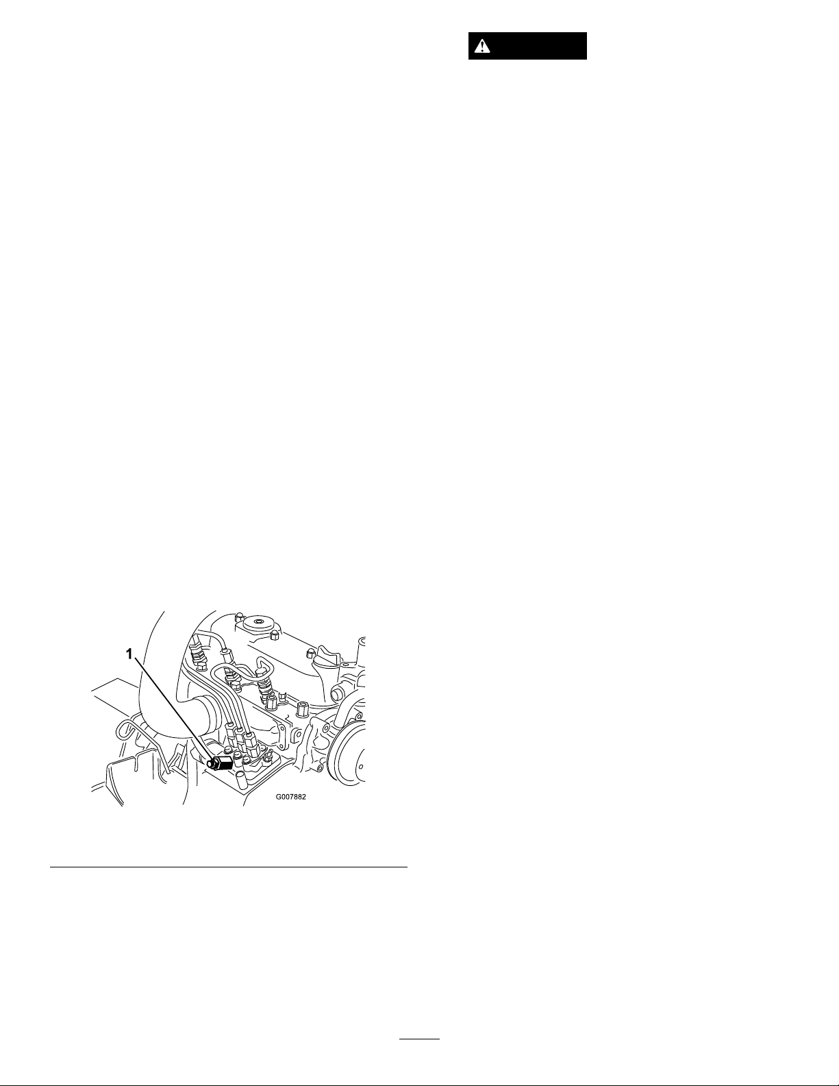
6.Installtheltercanisterbyhanduntilthegasket
contactsmountingsurface,thenrotateitanadditional
1/2turn.
7.Tightenthedrainplugonthebottomofthelter
canister.
CleaningtheFuelTank
ServiceInterval:Every2years
Drainandcleanfueltankevery2years.Also,removeand
cleanthein-linestrainersafterdrainingthetank.Useclean
dieselfueltoushoutthetank.
CAUTION
Theenginemaystartduringthisprocedure.
Movingfansandbeltsinarunningenginecan
severelyinjureyouorbystanders.
Keephands,ngers,looseclothing/jewelry,
andhairawayfromtheenginefanandbelt
duringthisprocedure.
5.LeavethekeyintheOnpositionuntilasolidstream
offuelowsoutaroundthescrew .
6.TightenthescrewandturnkeytotheOffposition.
Important:Drainandcleanthetankifthefuelsystem
becomescontaminatedorifthemachineistobestored
foranextendedperiod.
FuelLinesandConnections
ServiceInterval:Every400hours
Checkthefuellinesandconnections.Inspectthemfor
deterioration,damage,chafng,orlooseconnections.
BleedingtheFuelSystem
1.Parkthemachineonalevelsurface.Ensurethatthe
fueltankisatleasthalffull.
2.Unlatchandraisethehood.
3.Placearagundertheair-bleedscrewonthe
fuel-injectionpumpandopenit(Figure68).
Note:Normally,theengineshouldstartafterabove
bleedingproceduresarefollowed.However,ifengine
doesnotstart,airmaybetrappedbetweeninjection
pumpandinjectors;refertoBleedingAirfromthe
Injectors(page50).
Figure68
1.Fuel-injectionpumpbleedscrew
4.TurnthekeyintheignitionswitchtotheOnposition.
Theelectricfuelpumpwillbeginoperation,thereby
forcingairoutaroundtheairbleedscrew .
49
Page 50
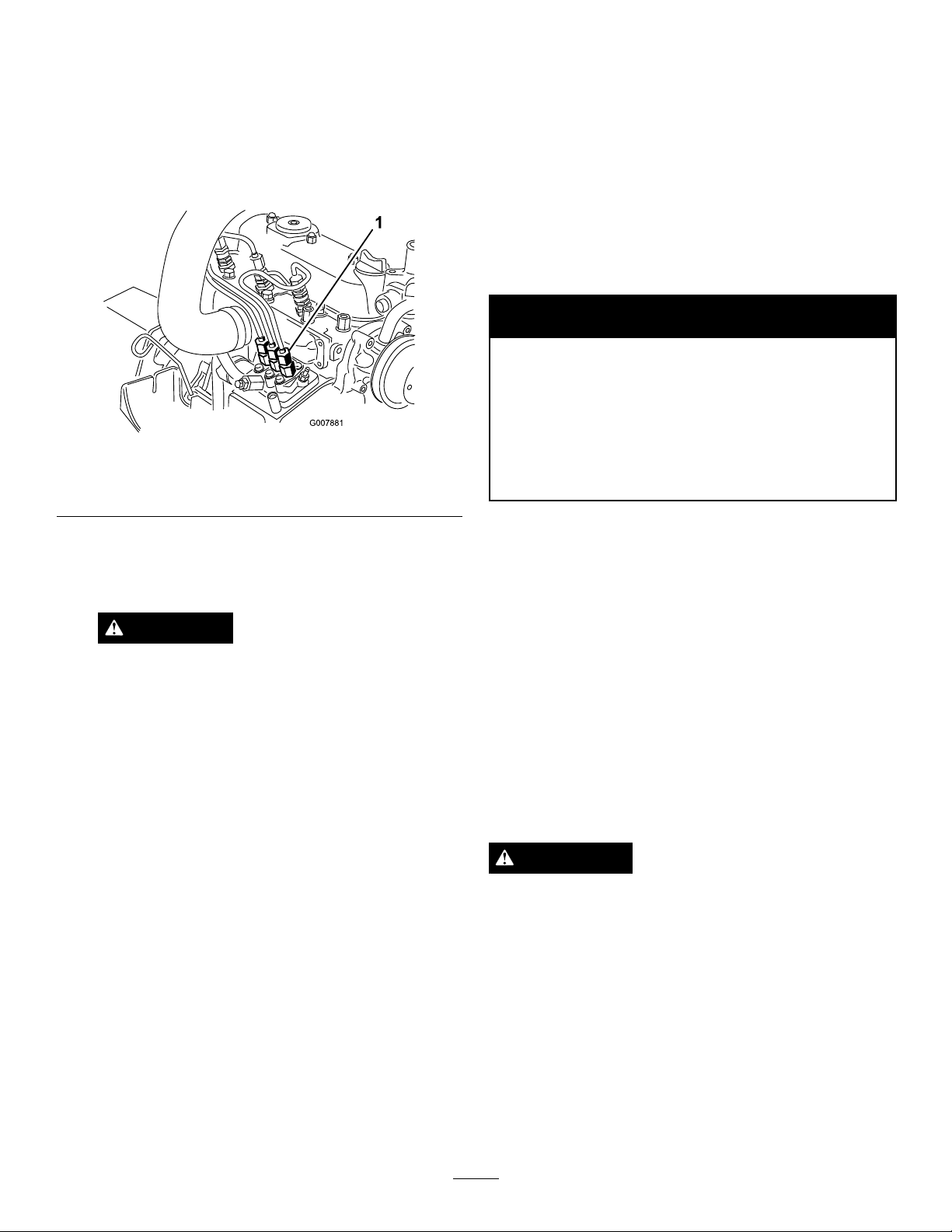
BleedingAirfromtheInjectors
ElectricalSystem
Note:Usethisprocedureonlyifthefuelsystemhasbeen
purgedofairthroughnormalprimingproceduresandengine
willnotstart;refertoBleedingtheFuelSystem(page49).
1.Placearagunderthepipeconnectioncomingfrom
theinjectionpumptotheNo.1injectornozzleas
illustratedin
1.PipeconnectionfromtheinjectionpumptotheNo.1
injectornozzle
Figure69.
Figure69
Maintenance
Important:Wheneverworkingwiththeelectrical
system,alwaysdisconnectthebatterycables,negative
(-)cablerst,topreventpossiblewiringdamagefrom
short-outs.
ServicingtheBattery
ServiceInterval:Every50hours
WARNING
CALIFORNIA
Proposition65Warning
Batteryposts,terminals,andrelated
accessoriescontainleadandleadcompounds,
chemicalsknowntotheStateofCalifornia
tocausecancerandreproductiveharm.
Washhandsafterhandling.
2.MovethethrottletotheFastposition.
3.TurntheignitionkeytheStartposition,andwatchthe
fuelowaroundtheconnector.
CAUTION
Theenginemaystartduringthisprocedure.
Movingfansandbeltsinarunningenginecan
severelyinjureyouorbystanders.
Keephands,ngers,looseclothing/jewelry,
andhairawayfromtheenginefanandbelt
duringthisprocedure.
4.Tightenthepipeconnectorsecurelywhenitattainsa
solidow .
5.TurnthekeytotheOffposition.
6.Repeatthisprocedurefortheremainingnozzles.
Keepthetopofthebatteryclean.Ifyoustorethemachinein
alocationwheretemperaturesareextremelyhigh,thebattery
willrundownmorerapidlythanifthemachineisstoredina
locationwherethetemperatureiscool.
Keepthetopofthebatterycleanbywashingitperiodically
withabrushdippedinammoniaorbicarbonateofsoda
solution.Flushthetopsurfacewithwateraftercleaningit.
Donotremovethellcapswhilecleaningthebattery.
Thebatterycablesmustbetightontheterminalstoprovide
goodelectricalcontact.
Ifcorrosionoccursattheterminals,disconnectthecables,
negative(-)cablerst,andscrapetheclampsandterminals
separately.Connectthecables,positive(+)cablerst,and
coattheterminalswithpetroleumjelly.
WARNING
Batteryterminalsormetaltoolscouldshortagainst
metalmachinecomponentscausingsparks.Sparks
cancausethebatterygassestoexplode,resulting
inpersonalinjury.
•Whenremovingorinstallingthebattery,donot
allowthebatteryterminalstotouchanymetal
partsofthemachine.
•Donotallowmetaltoolstoshortbetween
thebatteryterminalsandmetalpartsofthe
machine.
50
Page 51
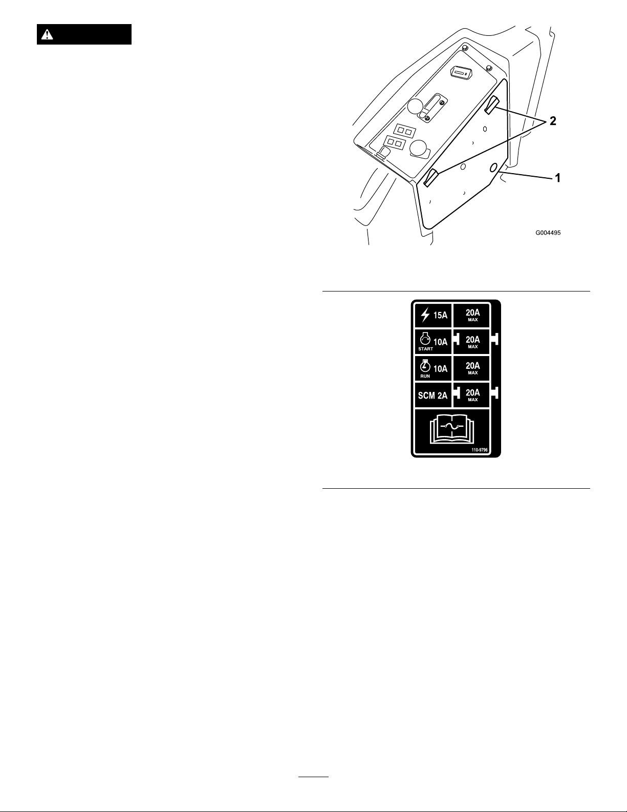
WARNING
Incorrectbatterycableroutingcoulddamagethe
machineandcablescausingsparks.Sparkscan
causethebatterygassestoexplode,resultingin
personalinjury.
•Alwaysdisconnectthenegative(black)battery
cablebeforedisconnectingthepositive(red)
cable.
•Alwaysconnectthepositive(red)batterycable
beforeconnectingthenegative(black)cable.
StoringtheBattery
Ifthemachinewillbestoredmorethan30days,removethe
batteryandchargeitfully .Eitherstoreitonashelforonthe
machine.Leavethecablesdisconnectedifitisstoredonthe
machine.Storethebatteryinacoolenvironmenttoprevent
thebatteryfromdischargingrapidly.Topreventthebattery
fromfreezing,makesureitisfullycharged.Thespecic
gravityofafullychargedbatteryis1.265to1.299.
1.Sidepanelcover
Figure70
2.Latches
CheckingtheFuses
Thefusesarelocatedunderthecontrolpanel.Accessthem
throughthesidepanelcover(Figure70).T oopentheside
panelcover,releasethe2latchesandpulloutonit.
Ifthemachinestopsorhasotherelectricalsystemissues,
checkthefuses.Graspeachfuseinturnandremovethem
oneatatime,checkingtoseeifanyareblown.Ifyouneed
toreplaceafuse,alwaysusethesametypeandamperage
ratedfuseastheoneyouarereplacing,otherwiseyoucould
damagetheelectricalsystem(refertothedecalnexttothe
fuses(Figure71)foradiagramofeachfuseanditsamperage).
Note:Ifafuseblowsfrequently,youprobablyhaveashort
intheelectricalsystemandshouldhaveitservicedbya
qualiedservicetechnician.
Figure71
51
Page 52
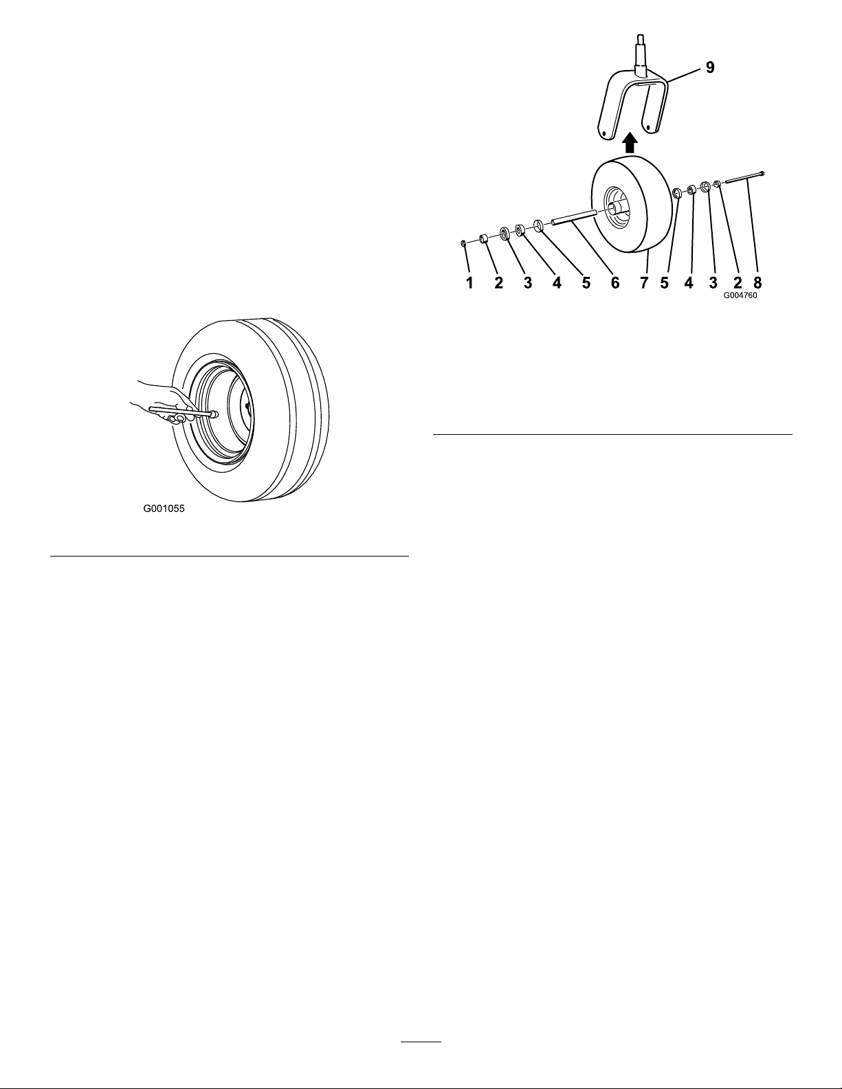
DriveSystem
Maintenance
CheckingtheTirePressure
ServiceInterval:Every50hours
Checkthepressureafterevery50operatinghoursormonthly,
whicheveroccursrst(Figure72).
Maintaintheairpressureinthefrontandreartires.The
correctairpressureis124kPa(18psi)inthereartiresand
172kPa(25psi)inthecasterwheels.Uneventirepressure
cancauseanunevencut.Checkthetireswhentheyarecold
togetthemostaccuratepressurereading.
Figure73
Figure72
ReplacingtheCasterWheels andBearings
1.Obtainanewcasterwheelassembly,conebearings,and
bearingsealsfromyourAuthorizedToroDistributor.
2.Removethelocknutfromtheboltholdingthecaster
wheelassemblybetweenthecasterfork(Figure73).
1.Nut
2.Bearingspacer
3.Outerbearingseal
4.Conebearing9.Casterfork
5.Innerbearingseal
3.Graspthecasterwheel,andslidetheboltoutofthe
forkorpivotarm.
4.Discardtheoldcasterwheelandbearings.
5.Assemblethecasterwheelbypushingthecone
bearingsandseals,packedwithgrease,intothewheel
hub,positionedasshowninFigure73.
6.Slidethespacerintothewheelhubthroughthe
bearings,captivatingthespacerinsidethewheelhub
with2bearingspacers.
Important:Ensurethattheseallipsarenot
foldedinward.
7.Installthecaster-wheelassemblybetweenthecastor
forkandsecureitinplacewiththeboltandlocknut.
8.Tightenthenutuntilthewheelnolongerspinsfreely,
thenbackitoffjustuntilthewheelspinsfreely.
6.Spacer
7.Casterwheel
8.Axlebolt
9.Attachagreaseguntothegreasettingonthe
casterwheelandllitwithNo.2general-purpose,
lithium-basedgrease.
52
Page 53
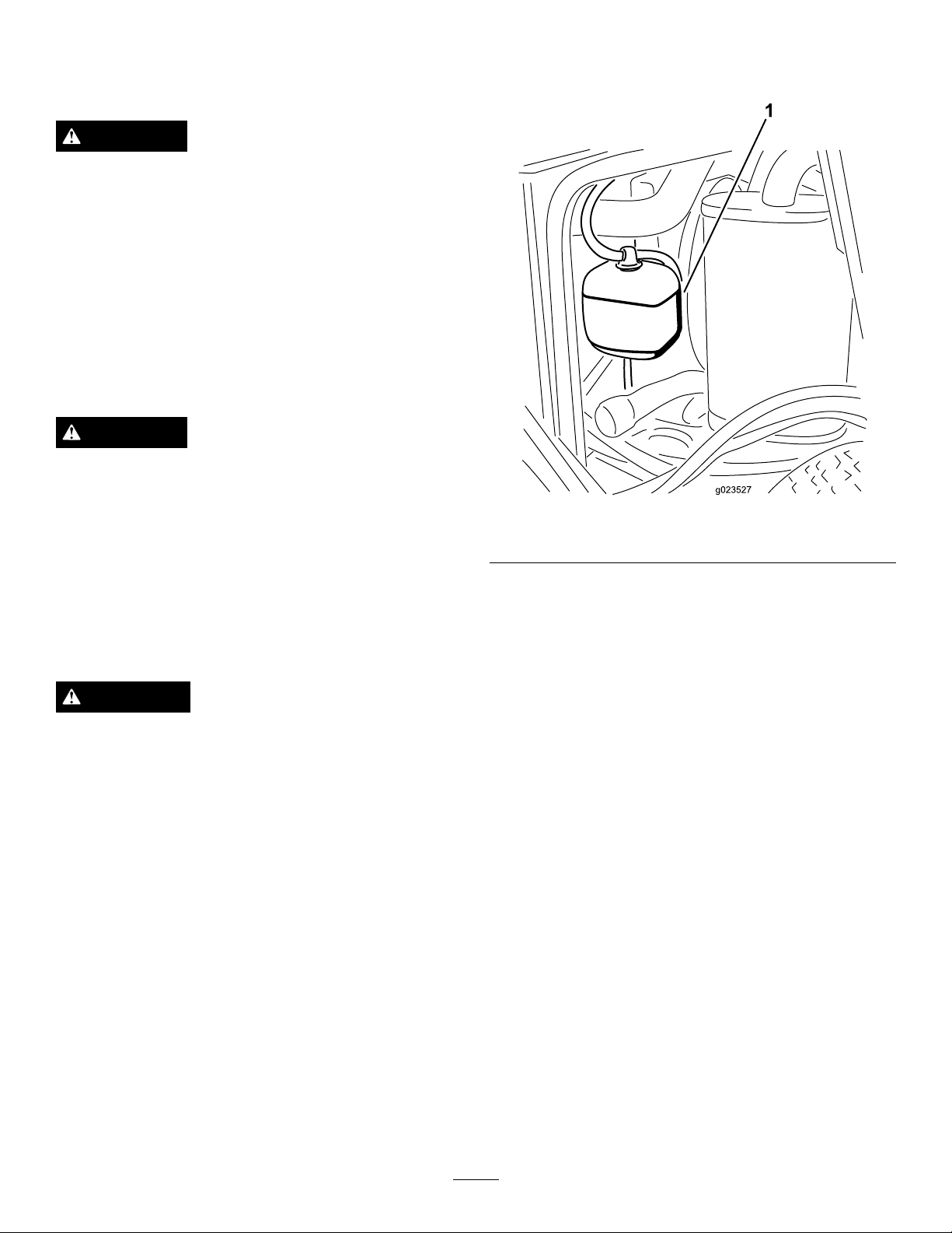
CoolingSystem
Maintenance
DANGER
Discharginghotpressurizedcoolantortouching
hotradiatorandsurroundingpartscancausesevere
burns.
•Donotremovetheradiatorcapwhentheengine
ishot.Alwaysallowtheenginetocoolatleast
15minutesoruntiltheradiatorcapiscool
enoughtotouchwithoutburningyourhand
beforeremovingtheradiatorcap.
•Donottouchradiatorandsurroundingparts
thatarehot.
DANGER
Therotatingfananddrivebeltcancausepersonal
injury.
•Donotoperatethemachinewithoutthecovers
inplace.
1.Checkthelevelofthecoolantintheexpansiontank
(
Figure74).Thecoolantlevelshouldbebetweenthe
marksonthesideofthetank.
Figure74
1.Expansiontank
•Keepngers,handsandclothingclearof
rotatingfananddrivebelt.
•Shutofftheengineandremovetheignitionkey
beforeperformingmaintenance.
CAUTION
Swallowingenginecoolantcancausepoisoning.
•Donotswallowenginecoolant.
•Keepoutofreachfromchildrenandpets.
CheckingtheCoolingSystem
ServiceInterval:Beforeeachuseordaily
Thecoolingsystemislledwitha50/50solutionofwater
andpermanentethyleneglycolantifreeze.Checkthelevelof
thecoolantintheexpansiontankatthebeginningofeachday
beforestartingtheengine.Thecapacityofthecoolingsystem
is6quarts(7.5l).
2.Ifcoolantlevelislow ,removetheexpansiontankcap
andreplenishthesystem.Donotoverll.
3.Installtheexpansiontankcap.
CleaningtheRadiator
ServiceInterval:Beforeeachuseordaily
Every1,500hours—Replacemovinghoses.
Every200hours—Inspectcoolingsystemhosesand
seals.Replacethemifcrackedortorn.
Every2years—Flushandreplacecoolingsystemuid.
Topreventtheenginefromoverheating,theradiatormust
bekeptclean.Normally,checktheradiatordailyand,if
necessary,cleananydebrisofftheseparts.However,itwill
benecessarytocheckandcleantheradiatorfrequentlyin
extremelydustyanddirtyconditions.
Note:Ifthemowerdeckorengineshutsoffdueto
overheating,rstchecktheradiatorforexcessivebuildupof
debris.
Cleantheradiatorasfollows:
1.Openthehood.
2.Workingfromthefansideoftheradiator,blowout
debriswithlowpressure(50psi)compressedair(do
notusewater).Repeatthestepfromthefrontofthe
radiatorandagainfromthefanside.
53
Page 54
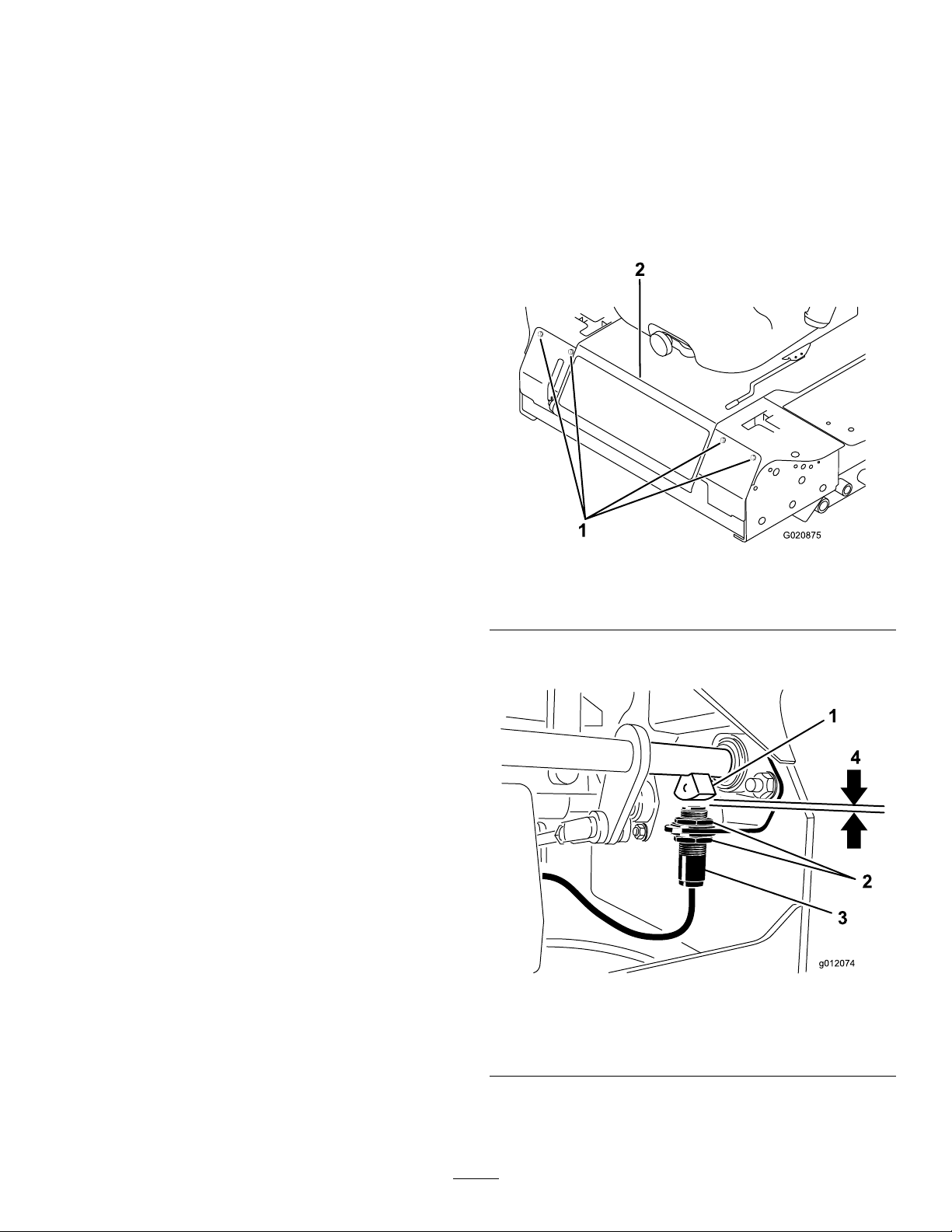
3.Aftertheradiatoristhoroughlycleaned,cleanout
1
2
G020875
debristhatmayhavecollectedinthechannelatthe
radiatorbase.
4.Closethehood.
BrakeMaintenance
AdjustingtheParkingBrake InterlockSwitch
1.Stopthemachine,movethedeckliftswitchfullyinto
theneutral-lockedposition,settheparkingbrake,and
removetheignitionkey.
2.Removetheboltssecuringthefrontpanelandremove
thepanel(
Figure75).
Figure75
1.Bolts
2.Controlpanel
3.Loosenthe2jamnutssecuringtheparkingbrake
interlockswitchtothemountingbracket.
Figure76
1.Brake-shaftsensor
2.Jamnuts
4.Movetheswitchupordownonthebracketuntilthe
distancebetweenthebrakeshaftsensorandtheswitch
plungeris5/32inch(3.9mm)(Figure76).
54
3.Parking-brake-interlock
switch
4.5/32inch(3.9mm)
Page 55
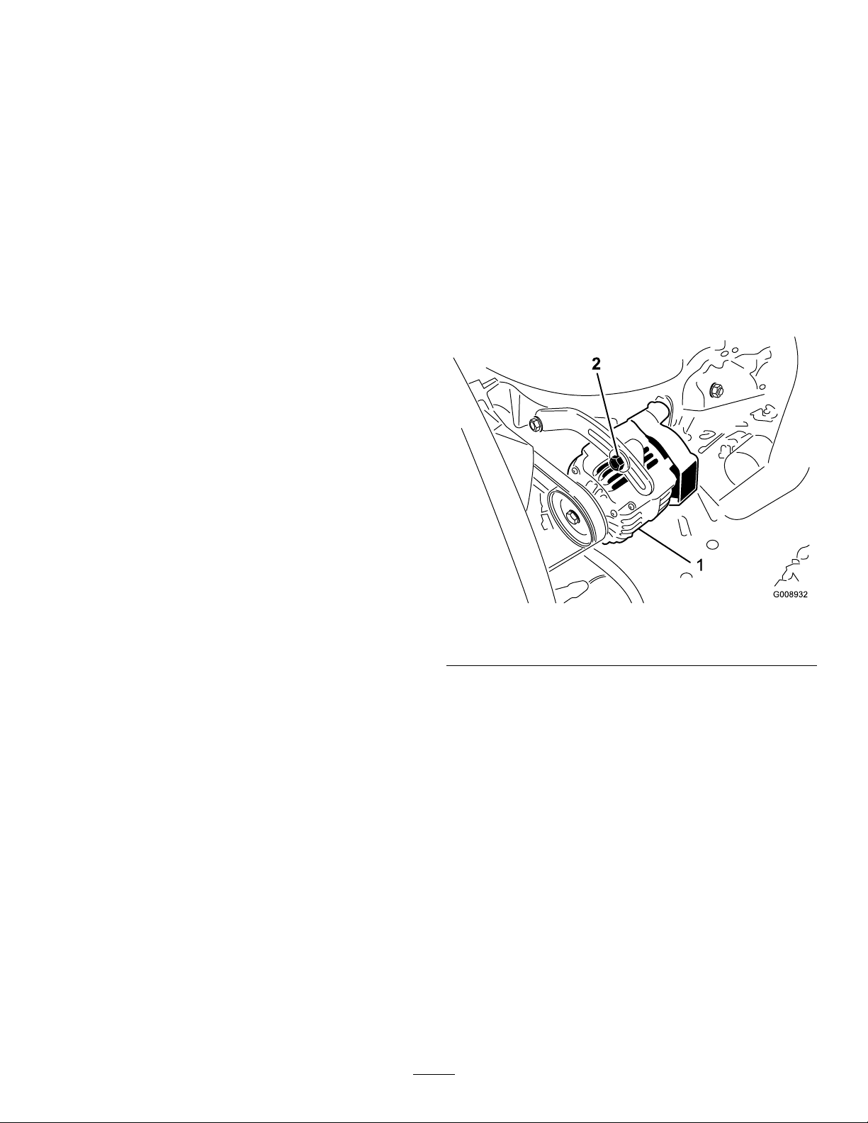
Note:Makesurethatthebrake-shaftsensordoesnot
contacttheswitchplunger.
BeltMaintenance
5.Securetheswitchjamnuts.
6.Testtheadjustmentasfollows:
A.Ensurethattheparkingbrakeisengagedandyou
arenotsittingontheseat,thenstarttheengine.
B.Movethecontrolleversoutoftheneutrallocked
position.
Theengineshouldstop.Ifnot,recheckthe
adjustmentyoumadetotheswitch.
7.Installthefrontpanel.
CheckingtheAlternatorBelt
ServiceInterval:Every100hours
Checktheconditionandtensionofthebelts(Figure77)after
every100operatinghours.
1.Propertensionwillallow10mm(3/8inch)deection
whenaforceof44N(10lb.)isappliedonthebelt
midwaybetweenthepulleys.
2.Ifthedeectionisnot10mm(3/8inch),loosenthe
alternatormountingbolts(
decreasethealternatorbelttensionandtightenthe
bolts.Checkthedeectionofthebeltagaintoensure
thatthetensioniscorrect.
Figure77).Increaseor
Figure77
1.Mountingbolt2.Alternator
ReplacingtheBladeDrive Belts
ServiceInterval:Every50hours
Thebladedrivebelts,tensionedbythespringloadedidler
pulleys,areverydurable.However,aftermanyhoursofuse,
thebeltswillshowsignsofwear.Signsofawornbeltare:
squealingwhenbeltisrotating,bladesslippingwhencutting
grass,frayededges,burnmarksandcracks.Replacethebelts
ifanyoftheseconditionsareevident.
1.Lowerthecuttingunittothe1inchheight-of-cut
setting,movethethrottlelevertotheSlowposition,
stoptheengine,settheparkingbrake,andremovethe
ignitionkey .
2.Removethebeltcoversfromthetopofthecuttingunit
andsetthecoversaside.
3.Usingabreakerbarorsimilartool,movetheidler
pulleyforthetopbelt(Figure78)awayfromthetop
55
Page 56
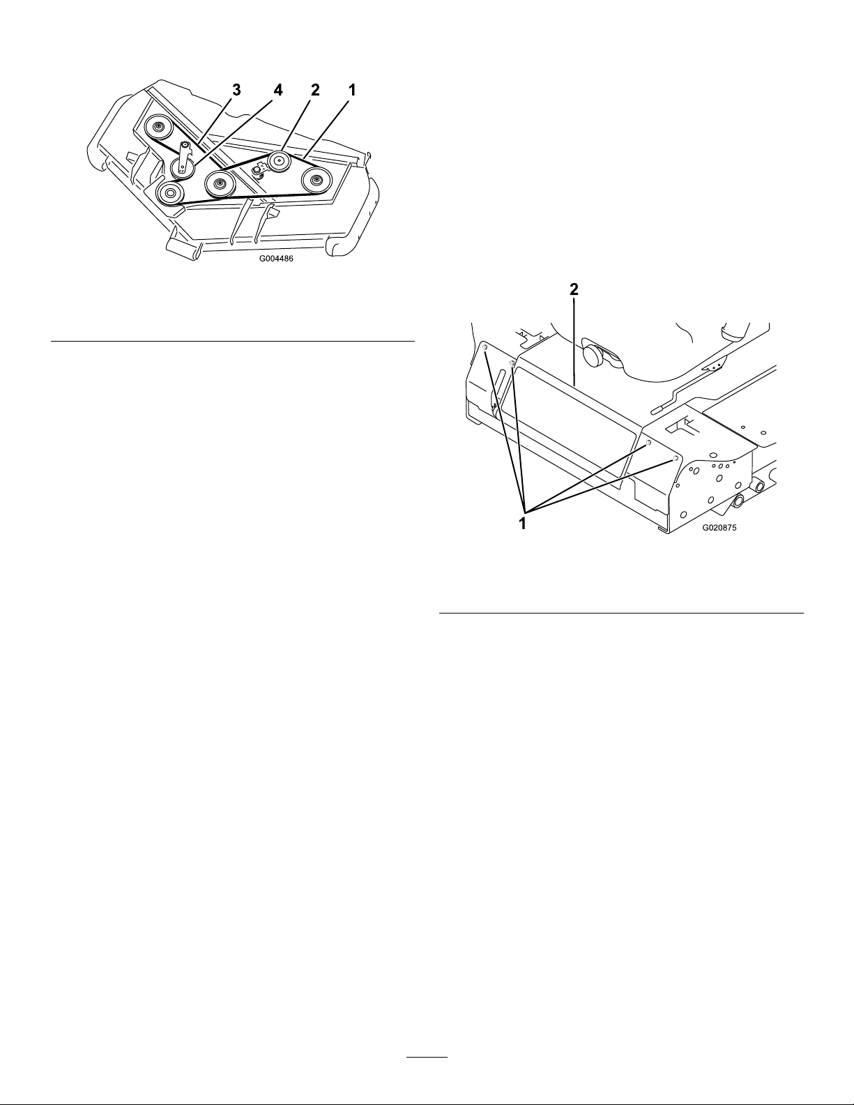
drivebelttoreleasethebelttensionandallowthebelt
1
2
G020875
tobeslippedoffthepulleys.
Figure78
1.Topbelt3.Bottombelt
2.Top-idlerpulley4.Bottom-idlerpulley
4.Usingabreakerbarorsimilartool,movetheidler
pulleyforthebottombelt(Figure78)awayfromthe
bottomdrivebelttoreleasethebelttensionandallow
thebelttobeslippedoffthepulleys.
5.Routeanewbeltaroundthegearboxpulley,bottom
spindlepulleys,andidlerpulleyassemblyasshownin
Figure78.
ControlsSystem
Maintenance
AdjustingtheControlLever NeutralInterlockSwitch
1.Stopthemachine,movethedeckliftswitchfullyinto
theneutral-lockedposition,settheparkingbrake,and
removetheignitionkey.
2.Removetheboltssecuringthefrontpanelandremove
thepanel(Figure79).
6.Routeanewbeltaroundthetopspindlepulleysand
idlerpulleyassemblyasshowninFigure78.
7.Installthebeltcovers.
Figure79
1.Bolts
2.Controlpanel
3.Loosenthe2screwssecuringtheinterlockswitch
(Figure80).
56
Page 57
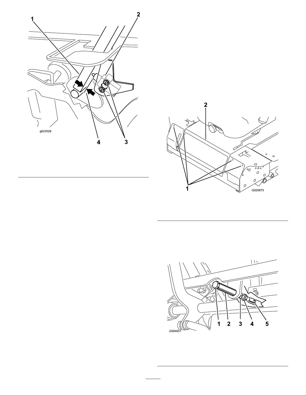
Figure80
1
2
G020875
1.Controllever3.Screws
2.Neutralinterlockswitch
4.0.015to0.045inch(0.4to
1mm)
AdjustingtheControlLever NeutralReturn
Ifthemotioncontrolleversdonotalignwiththeneutralslots
whenreleasedfromthereversedriveposition,adjustmentis
required.Adjusteachlever,spring,androdseparately.
1.DisengagethePTO,movethecontrollevertothe
neutrallockedposition,andsettheparkingbrake.
2.MovethethrottlelevertotheSlowposition,stopthe
engine,removethekey,andwaitforallmovingpartsto
stopbeforeleavingtheoperatingposition.
3.Removetheboltssecuringthefrontpanelandremove
thepanel(
Figure81).
4.Holdingthecontrolleveragainsttheframe,movethe
switchtowardtheleveruntilthedistancebetweenlever
andswitchbodyis0.015to0.045inch(0.4to1mm)
(Figure80).
5.Securetheswitch.
6.Repeatsteps3to5fortheotherlever.
7.Installthefrontpanel.
Figure81
1.Bolts
2.Controlpanel
4.Movethecontrollevertotheneutralpositionbutnot
locked(Figure83).
5.Pulltheleverbackuntiltheclevispin(onanarm
abovethepivotshaft)contactstheendoftheslot(just
beginningtoputpressureonthespring)(
Figure82).
Figure82
1.Clevispin
2.Slot
3.Jamnuts
57
4.Adjustmentbolt
5.Yoke
Page 58
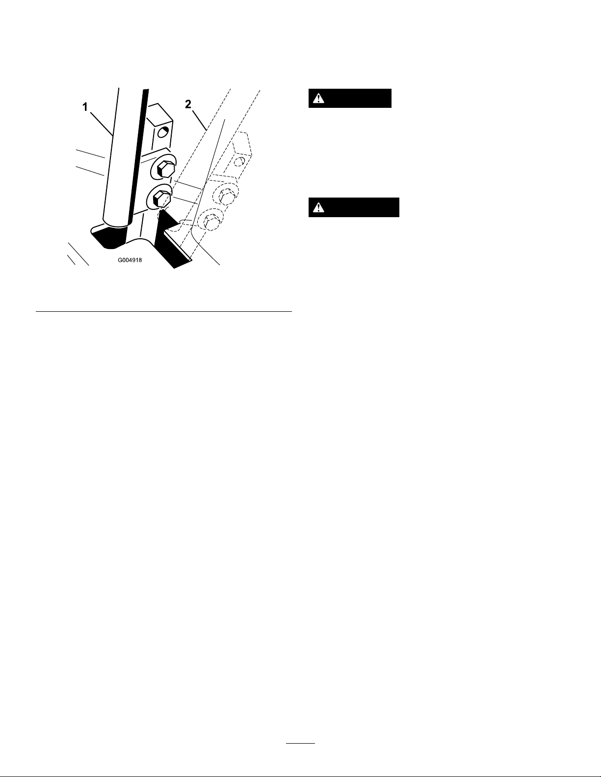
6.Checkwherethecontrolleverisrelativetonotchin
console(Figure83).
Note:Itshouldbecenteredallowinglevertopivot
outwardtotheneutrallockposition.
AdjustingtheTractionDrive forNeutral
Thisadjustmentmustbemadewithdrivewheelsturning.
DANGER
Mechanicalorhydraulicjacksmayfailtosupport
themachineandcauseaseriousinjury.
•Usejackstandswhensupportingthemachine.
•Donotusehydraulicjacks.
WARNING
Theenginemustberunningtoperformthis
adjustment.Contactwithmovingpartsorhot
surfacesmaycausepersonalinjury.
Figure83
1.Neutralposition2.Neutrallockedposition
7.Ifadjustmentisneeded,loosenthenutandjamnut
againsttheyoke(Figure82).
8.Applyingslightrearwardpressureonthemotion
controllever,turntheheadoftheadjustmentbolt
intheappropriatedirectionuntilthecontrolleveris
centeredintheneutrallockposition(
Note:Keepingrearwardpressureontheleverwill
keepthepinattheendoftheslotandallowthe
adjustmentbolttomovethelevertotheappropriate
position.
9.Tightenthenutandjamnut(Figure82).
10.Repeatsteps4through9fortheothercontrollever.
11.Installthefrontpanel.
Figure82).
Keephands,feet,face,clothing,andotherbody
partsawayfromrotatingparts,mufer,andother
hotsurfaces.
1.Raisetheframeontostablejackstandssothatthedrive
wheelscanrotatefreely.
2.Slideseatforward,unlatchit,andswingitupand
forward.
3.Disconnecttheelectricalconnectorfromtheseat
safetyswitch.
4.Temporarilyinstallajumperwireacrossterminalsin
thewiringharnessconnector.
5.Starttheengine,ensurethatthethrottleleverismidway
betweentheFastandSlowpositions,andreleasethe
parkingbrake.
Note:Themotioncontrolleversmustbeinthe
neutrallockedpositionwhilemakinganyadjustments.
6.Adjustthepumprodlengthononesidebyrotating
thehexshaft,intheappropriatedirection,untilthe
correspondingwheelisstillorslightlycreepingin
reverse(Figure84).
58
Page 59
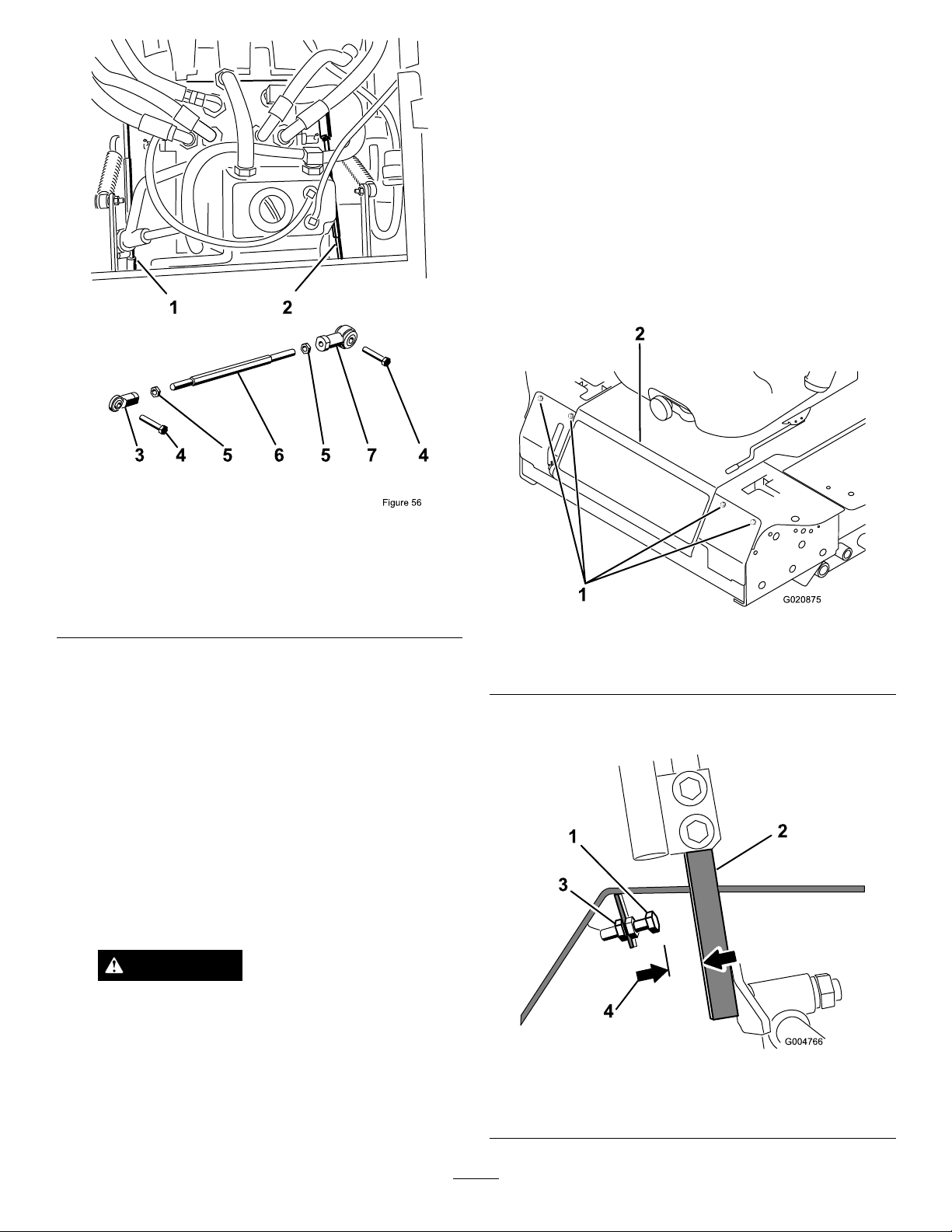
13.Lowertheseatintoposition.
1
2
G020875
14.Removethejackstands.
AdjustingtheMaximum GroundSpeed
1.DisengagethePTO ,movethemotioncontrolleversto
theneutrallockedposition,andsettheparkingbrake.
2.MovethethrottlelevertotheSlowposition,stopthe
engine,removethekey,andwaitforallmovingpartsto
stopbeforeleavingtheoperatingposition.
3.Removetheboltssecuringthefrontpanelandremove
thepanel(
Figure85).
Figure84
1.Rightpumprod5.JamNut
2.Leftpumprod6.Hexshaft
3.Balljoint7.Balljoint
4.Bolt
7.Movethemotioncontrolleverforwardandreverse,
thenbacktoneutral.Thewheelmuststopturningor
slightlycreepinreverse.
8.MovethethrottlelevertotheFastposition.Makesure
thatthewheelremainsstoppedorslightlycreepsin
reverse;adjustitifnecessary.
9.Repeatsteps6through8fortheothersideofthe
machine.
10.Tightenthejamnutsattheballjoints(
Figure82).
11.MovethethrottlelevertotheSlowpositionandstop
theengine.
12.Removethejumperwirefromthewireharness
connectorandplugtheconnectorintotheseatswitch.
WARNING
Figure85
1.Bolts
2.Controlpanel
4.Loosenthejamnutonthestopboltforoneofthe
controllevers(Figure86).
Electricalsystemwillnotperformproper
safetyshutoffwithjumperwireinstalled.
•Removejumperwirefromwireharness
connectorandplugconnectorintoseat
switchwhenadjustmentiscompleted.
•Neveroperatethisunitwithjumper
installedandseatswitchbypassed.
Figure86
1.Stopbolt
2.Controllever4.0.060inch(1.5mm)
59
3.Jamnut
Page 60
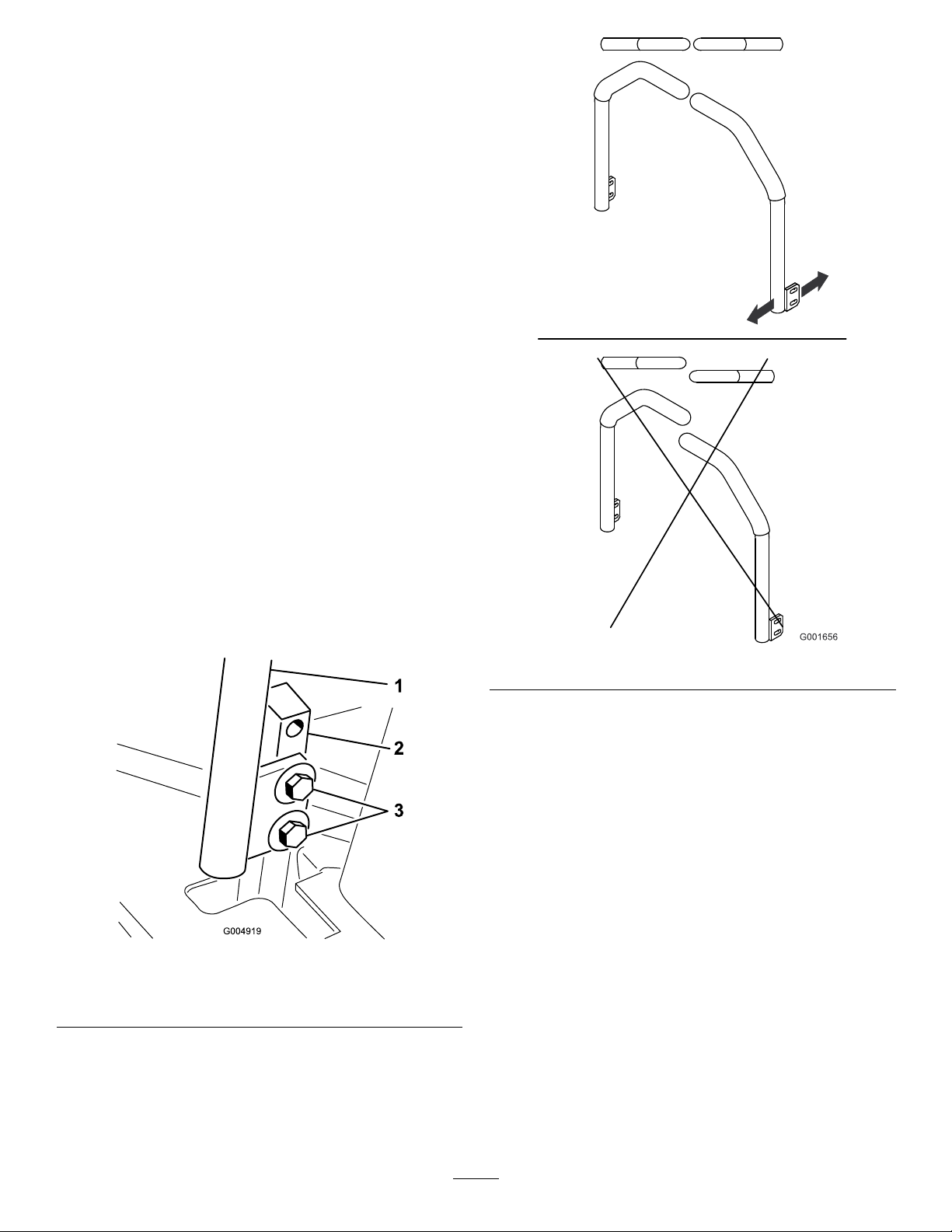
5.Threadthestopboltallthewayin(awayfromthe
controllever).
6.Pushthecontrolleverallthewayforwarduntilitstops
andholditthere.
7.Threadthestopboltout(towardthecontrollever)
untilthereisagapof0.060inch(1.5mm)betweenthe
headofthestopboltandthecontrollever.
8.Tightenthejamnuttosecurethestopboltinplace.
9.Repeatsteps4through8fortheothercontrollever.
10.Installthefrontpanel.
Note:Ifyouwishtoreducethemaximummachinespeed,
setthespeedforbothcontrolleversasdirectedabove,then
backeachstopboltoutanequalamounttowardthecontrol
leveruntilyoureachthemaximumspeedyoudesire(youwill
likelyhavetotestyouradjustmentseveraltimes).Ensurethat
themachinedrivesstraightanddoesnotturnwhenboth
controlleversarepushedallthewayforward.Ifthemachine
turns,youdonothavethestopboltsevenlysetandwillneed
toadjustthemfurther.
AdjustingtheTracking
1.DisengagethePTO ,movethemotioncontrolleversto
theneutrallockedpositionandsettheparkingbrake.
2.MovethethrottlelevertotheSlowposition,stopthe
engine,removethekey,andwaitforallmovingpartsto
stopbeforeleavingtheoperatingposition.
3.Loosentheboltssecuringthecontrollevers(Figure87)
Figure87
Figure88
1.Controllever
2.Control-leverpost
3.Bolts
4.Havesomeonepushthecontrol-leverposts(notthe
controllevers)allthewayforwardintothemaximum
speedpositionandholdthemthere.
5.Adjustthecontrolleverssothattheylineup(
andtightenthebolts,securingtheleverstotheposts.
Figure88)
60
Page 61
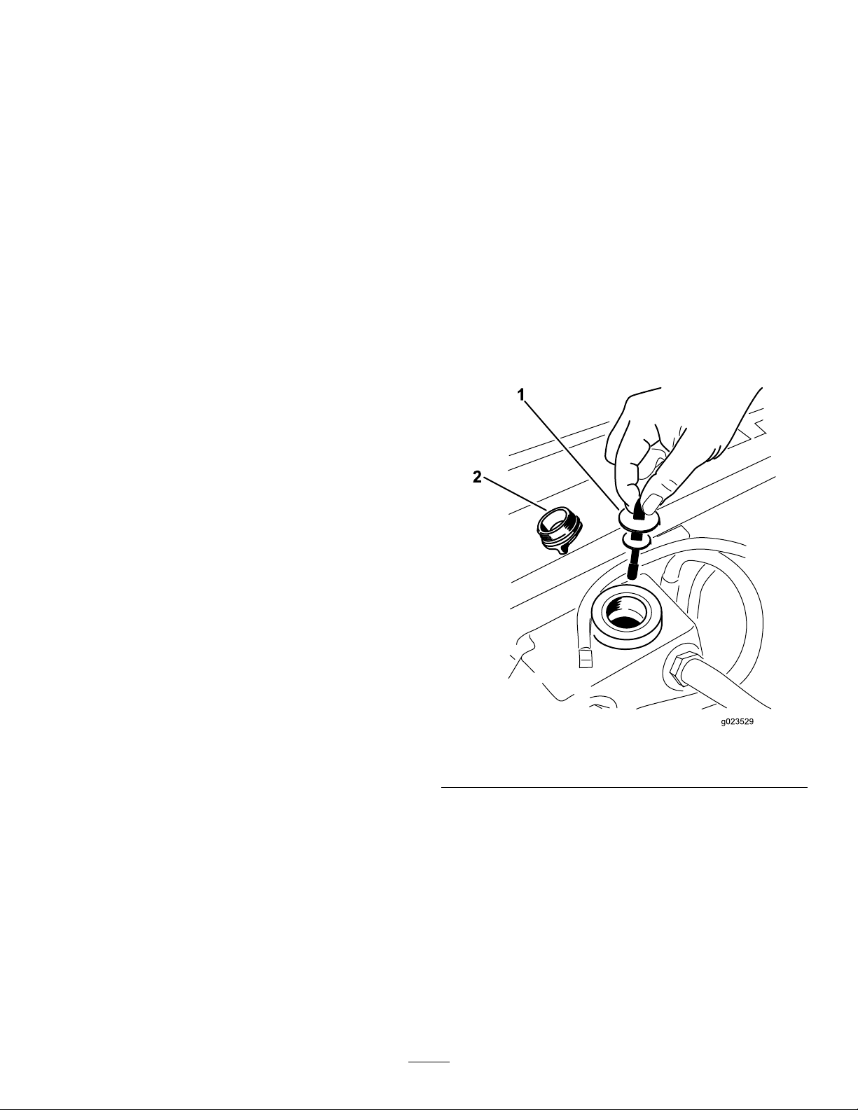
HydraulicSystem
Maintenance
Thehydraulicsystemislledatthefactorywithapproximately
4.7L(5USqt)ofhigh-qualitytransmission/tractorhydraulic
uid.Thebesttimetocheckthehydraulicuidiswhenitis
cold.Themachineshouldbeinthetransportconguration.
IftheuidlevelisbelowtheAddmarkonthedipstick,add
uidtobringtheleveltothemiddleoftheacceptablerange.
Donotoverllthesystem.Iftheuidlevelisbetweenthe
FullmarkandtheAddmark,noadditionaluidisrequired.
Therecommendedreplacementuidis:
ToroPremiumTransmission/HydraulicTractorFluid
(Availablein5USgallonpailsor55USgallondrums.
SeethepartsdocumentationorT orodistributorforpart
numbers.)
CheckingtheHydraulic System
ServiceInterval:Beforeeachuseordaily
Checkthelevelofthehydraulicuidbeforetheengineisrst
startedanddailythereafter.
1.Positionthemachineonalevelsurface.
2.Placethecontrolsintheneutrallockedpositionand
starttheengine.
Note:RunengineatlowestpossibleRPMtopurge
thesystemofair.DonotengagethePTO.
3.Raisethedecktoextendliftcylinders,stoptheengine,
andremovethekey.
4.Raisetheseattoaccessthehydraulicuidtank.
Alternativeuids:IftheTorouidisnotavailable,youcan
useMobil®424hydraulicuid.
Note:Torowillnotassumeresponsibilityfordamagecaused
byimpropersubstitutions.
Note:Manyhydraulicuidsarealmostcolorless,makingit
difculttospotleaks.Areddyeadditiveforthehydraulic
systemoilisavailablein20ml(2/3oz)bottles.Onebottle
issufcientfor15to22L(4to6USgallons)ofhydraulic
oil.Orderpartnumber44-2500fromyourAuthorizedToro
Distributor.
5.Removethehydraulicllcap(
neck.
Figure89
Figure89)fromtheller
1.Dipstick2.Fillcap
6.Removethedipstickandwipeitwithacleanrag
(Figure89).
7.Placethedipstickintothellerneck;thenremoveit
andchecklevelofuid(Figure89).
Note:Iflevelisnotwithinnotchedareaofthe
dipstick,addenoughhighqualityhydraulicuidto
raiseleveltowithinthenotchedarea.Donotoverll.
8.Replacethedipstickandthreadthellcapnger-tight
ontollerneck.
9.Checkallhosesandttingsforleaks.
61
Page 62
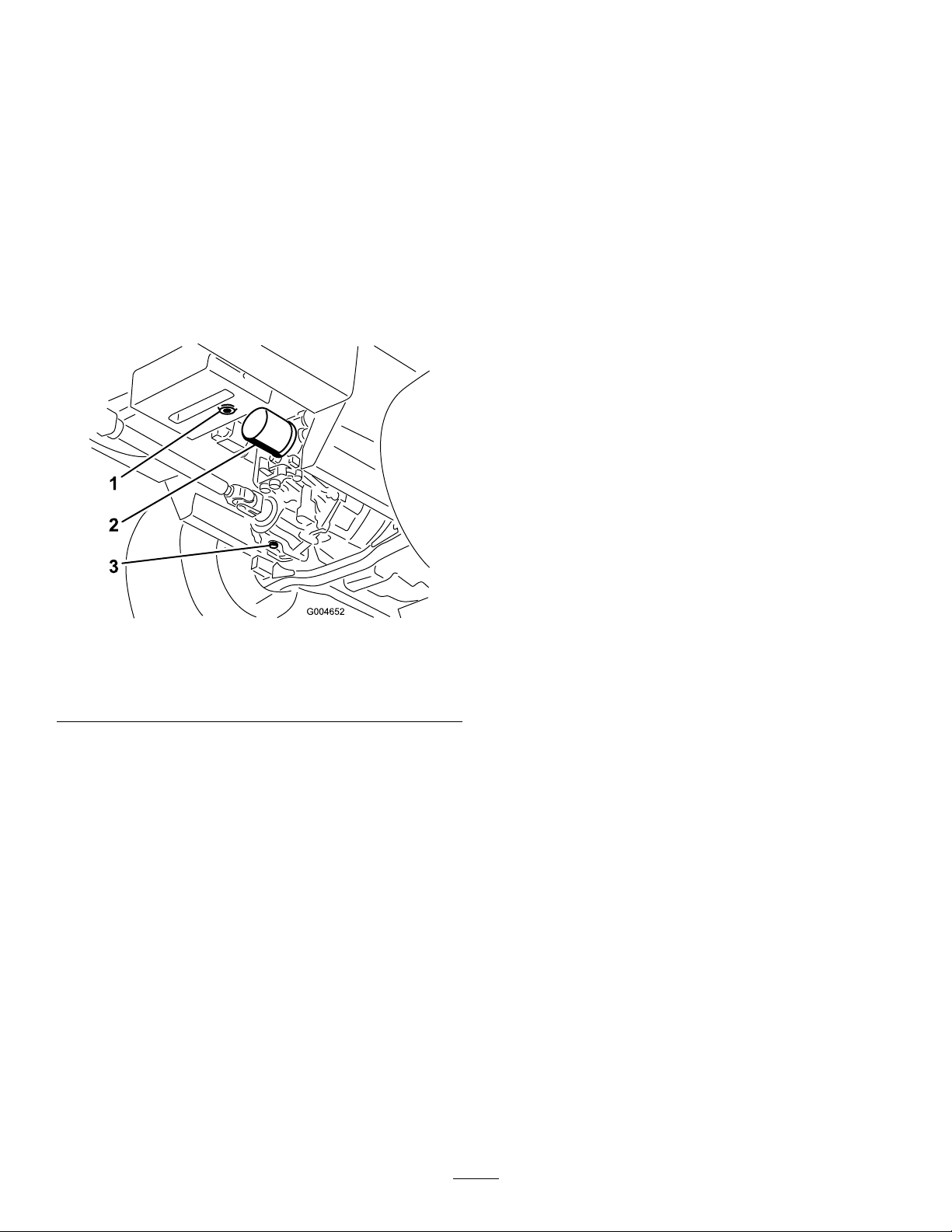
ChangingtheHydraulicOil AndFilter
Cleaning
ServiceInterval:Aftertherst200hours
Every800hours
1.DisengagethePTO ,movethemotioncontrolleversto
theneutrallockedposition,andsettheparkingbrake.
2.MovethethrottlelevertotheSlowposition,stopthe
engine,removethekey,andwaitforallmovingpartsto
stopbeforeleavingtheoperatingposition.
3.Placealargepanunderthehydraulicreservoirand
transmissioncaseandremovetheplugs,drainingallof
thehydraulicuid(
Figure90).
CleaningUndertheMower
ServiceInterval:Beforeeachuseordaily
Removethegrassbuildupunderthemowerdaily.
1.DisengagethePTO ,movethemotioncontrolleversto
theneutrallockedposition,andsettheparkingbrake.
2.MovethethrottlelevertotheSlowposition,stopthe
engine,removethekey,andwaitforallmovingpartsto
stopbeforeleavingtheoperatingposition.
3.Raisethemowertothetransportposition.
4.Raisethefrontofthemachinebyusingjackstands.
5.Thoroughlycleantheundersideofthemowerwith
water.
WasteDisposal
Engineoil,batteries,hydraulicoil,andenginecoolantare
pollutants.Disposeoftheseaccordingtoyourstateandlocal
regulations.
Figure90
1.Hydraulicreservoirdrain
plug
2.Filter
4.Cleantheareaaroundthehydraulicoillterand
removeit(Figure90).
5.Immediatelyinstallanewhydraulicoillter.
6.Installthehydraulicreservoirandtransmissioncase
drainplugs.
7.Fillthereservoirtotheproperlevel(approximately6
quarts);referto
30).
8.Starttheengineandcheckforoilleaks.Allowthe
enginetorunforaboutveminutes,thenshutitoff.
9.After2minutes,checkthelevelofthehydraulicuid;
referto
CheckingtheHydraulicSystem(page30).
CheckingtheHydraulicSystem(page
3.Transmissioncasedrain
plug
62
Page 63
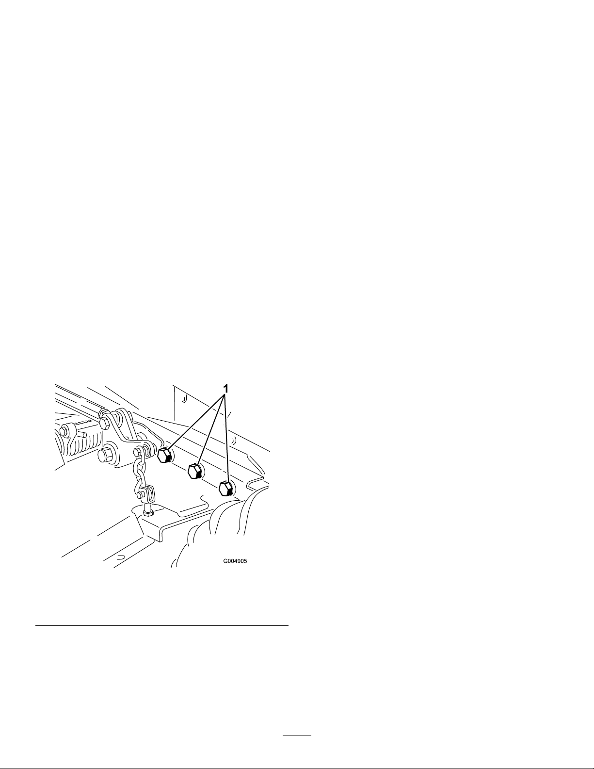
Storage
Machine
1.Thoroughlycleanthemachine,deckandtheengine,
payingspecialattentiontotheseareas:
•Radiatorandradiatorscreen
•Underneaththedeck
•Underthedeckbeltcovers
•Counterbalancesprings
7.Servicethebatteryandcablesasfollows:
A.Removethebatteryterminalsfromthebattery
posts.
B.Cleanthebattery,terminals,andpostswithawire
brushandbakingsodasolution.
C.Coatthecableterminalsandbatterypostswith
Grafo112Xskin-overgrease(ToroPartNo.
505-47)orpetroleumjellytopreventcorrosion.
D.Slowlyrechargethebatteryfor24hoursevery60
daystopreventleadsulfationofthebattery.
•PTOshaftassembly
•Allgreasettingsandpivotpoints
•Removethecontrolpanelandcleanoutinsideof
thecontrolbox
•Beneaththeseatplateandtopofthetransmission
2.Checkandadjustfrontandreartractortirepressure;
referto
3.Remove,sharpen,andbalancethemowerblades.
Installthebladesandtorquethebladefastenersto
115-149N-m(85-110ft-lb).
4.Checkallfastenersforloosenessandtightenthemas
necessary.Especiallytorquethe6boltssecuringthe
mowerdeckframetothetractionunit(
359N-m(265ft-lb).
CheckingtheTirePressure(page52).
Figure91)to
Engine
1.Draintheengineoilfromtheoilpanandreplacethe
drainplug.
2.Replacetheoillter.
3.Filltheenginewiththerecommendedmotoroil.
4.Starttheengineandrunitatidlespeedfor2minutes.
5.Drainthefuelfromthefueltank,fuellines,pump,
lter,andseparator.Flushthefueltankwithclean
dieselfuelandconnectallfuellines.
6.Thoroughlycleanandservicetheaircleanerassembly.
7.Sealtheaircleanerinletandtheexhaustoutletwith
weatherproofmaskingtape.
8.Checktheoilllercapandfueltankcaptoensurethat
theyaresecurelyinplace.
Figure91
Rightsidenotshown.
1.Bolts
5.Greaseoroilallgreasettings,pivotpoints,and
transmissionby-passvalvepins.Wipeoffanyexcess
lubricant.
6.Lightlysandandusetouchuppaintonpaintedareas
thatarescratched,chippedorrusted.Repairanydents
inthemetalbody.
63
Page 64

Notes:
64
Page 65

Notes:
65
Page 66

Notes:
66
Page 67

InternationalDistributorList
Distributor:
AgrolancKft
BalamaPrimaEngineeringEquip.HongKong85221552163
B-RayCorporation
CascoSalesCompany
CeresS.A.CostaRica
CSSCTurfEquipment(pvt)Ltd.SriLanka
CyrilJohnston&Co.
CyrilJohnston&Co.RepublicofIreland
EquiverMexico525553995444ParklandProductsLtd.NewZealand6433493760
FemcoS.A.Guatemala
ForGarderOU
G.Y .K.CompanyLtd.
GeomechanikiofAthensGreece
GolfinternationalTurizm
GuandongGoldenStarChina
HakoGroundandGardenSweden
HakoGroundandGarden
HayterLimited(U.K.)
HydroturfInt.CoDubai
HydroturfEgyptLLC
IrrimacPortugal351212388260T oroEuropeNVBelgium3214562960
IrrigationProductsInt'lPvtLtd.India00914424494387ValtechMorocco212537663636
JeanHeybroekb.v.Netherlands31306394611VictusEmakPoland48618238369
Country:
Hungary3627539640
Korea82325512076
PuertoRico7877888383
NorthernIreland442890813121
Estonia3723846060
Japan81726325861
Turkey902163365993Riversa
Norway4722907760
UnitedKingdom441279723444
UnitedArabEmirates97143479479T-MarktLogisticsLtd.Hungary3626525500
Egypt2025194308ToroAustraliaAustralia61395807355
PhoneNumber:Distributor:
5062391138
94112746100
442890813121
5024423277
30109350054
862087651338
4635100000
MaquiverS.A.Colombia
MaruyamaMfg.Co.Inc.
Mountelda.s.CzechRepublic
Mountelda.s.Slovakia
MunditolS.A.
NormaGarden
OslingerTurfEquipmentSA
OyHakoGroundandGardenAb
Perfetto
PratoverdeSRL.
Prochaska&Cie
RTCohen2004Ltd.
LelyTurfcare
SolvertS.A.S.
SpyprosStavrinidesLimitedCyprus
SurgeSystemsIndiaLimited
Country:
Japan81332522285
Argentina541148219999
Russia749541 16120
Ecuador59342396970
Finland35898700733
Poland48618208416
Italy390499128128
Austria4312785100
Israel97298617979
Spain
Denmark4566109200
France33130817700
India911292299901
PhoneNumber:
5712364079
420255704220
420255704220
34952837500
35722434131
EuropeanPrivacyNotice
TheInformationToroCollects
ToroWarrantyCompany(Toro)respectsyourprivacy.Inordertoprocessyourwarrantyclaimandcontactyouintheeventofaproductrecall,weaskyou
tosharecertainpersonalinformationwithus,eitherdirectlyorthroughyourlocalT orocompanyordealer.
TheT orowarrantysystemishostedonserverslocatedwithintheUnitedStateswhereprivacylawmaynotprovidethesameprotectionasapplies
inyourcountry.
BYSHARINGYOURPERSONALINFORMATIONWITHUS,YOUARECONSENTINGTOTHEPROCESSINGOFYOURPERSONALINFORMA TION
ASDESCRIBEDINTHISPRIVACYNOTICE.
TheWayT oroUsesInformation
Toromayuseyourpersonalinformationtoprocesswarrantyclaims,tocontactyouintheeventofaproductrecallandforanyotherpurposewhichwetell
youabout.ToromayshareyourinformationwithT oro'safliates,dealersorotherbusinesspartnersinconnectionwithanyoftheseactivities.Wewillnot
sellyourpersonalinformationtoanyothercompany.Wereservetherighttodisclosepersonalinformationinordertocomplywithapplicablelawsand
withrequestsbytheappropriateauthorities,tooperateoursystemsproperlyorforourownprotectionorthatofotherusers.
RetentionofyourPersonalInformation
Wewillkeepyourpersonalinformationaslongasweneeditforthepurposesforwhichitwasoriginallycollectedorforotherlegitimatepurposes
(suchasregulatorycompliance),orasrequiredbyapplicablelaw.
Toro'sCommitmenttoSecurityofYourPersonalInformation
Wetakereasonableprecautionsinordertoprotectthesecurityofyourpersonalinformation.Wealsotakestepstomaintaintheaccuracyandcurrent
statusofpersonalinformation.
AccessandCorrectionofyourPersonalInformation
Ifyouwouldliketorevieworcorrectyourpersonalinformation,[email protected].
AustralianConsumerLaw
AustraliancustomerswillnddetailsrelatingtotheAustralianConsumerLaweitherinsidetheboxoratyourlocalT oroDealer.
374-0269RevH
Page 68

TheToroTotalCoverageGuarantee
ALimitedWarranty
ConditionsandProductsCovered
TheToroCompanyanditsafliate,ToroWarrantyCompany ,pursuant
toanagreementbetweenthem,jointlywarrantyourToroCommercial
product(“Product”)tobefreefromdefectsinmaterialsorworkmanship
fortwoyearsor1500operationalhours*,whicheveroccursrst.This
warrantyisapplicabletoallproductswiththeexceptionofAerators
(refertoseparatewarrantystatementsfortheseproducts).Wherea
warrantableconditionexists,wewillrepairtheProductatnocosttoyou
includingdiagnostics,labor,parts,andtransportation.Thiswarranty
beginsonthedatetheProductisdeliveredtotheoriginalretailpurchaser.
*Productequippedwithanhourmeter.
InstructionsforObtainingWarrantyService
YouareresponsiblefornotifyingtheCommercialProductsDistributoror
AuthorizedCommercialProductsDealerfromwhomyoupurchasedthe
Productassoonasyoubelieveawarrantableconditionexists.Ifyouneed
helplocatingaCommercialProductsDistributororAuthorizedDealer,or
ifyouhavequestionsregardingyourwarrantyrightsorresponsibilities,
youmaycontactusat:
ToroCommercialProductsServiceDepartment
ToroWarrantyCompany
811 1LyndaleAvenueSouth
Bloomington,MN55420-1196
952–888–8801or800–952–2740
E-mail:[email protected]
OwnerResponsibilities
AstheProductowner,youareresponsibleforrequiredmaintenance
andadjustmentsstatedinyourOperator'sManual.Failuretoperform
requiredmaintenanceandadjustmentscanbegroundsfordisallowinga
warrantyclaim.
ItemsandConditionsNotCovered
Notallproductfailuresormalfunctionsthatoccurduringthewarranty
periodaredefectsinmaterialsorworkmanship.Thiswarrantydoesnot
coverthefollowing:
•Productfailureswhichresultfromtheuseofnon-Tororeplacement
parts,orfrominstallationanduseofadd-on,ormodiednon-T oro
brandedaccessoriesandproducts.Aseparatewarrantymaybe
providedbythemanufactureroftheseitems.
•Productfailureswhichresultfromfailuretoperformrecommended
maintenanceand/oradjustments.Failuretoproperlymaintainyour
ToroproductpertheRecommendedMaintenancelistedinthe
Operator’sManualcanresultinclaimsforwarrantybeingdenied.
•ProductfailureswhichresultfromoperatingtheProductinan
abusive,negligent,orrecklessmanner.
•Partssubjecttoconsumptionthroughuseunlessfoundtobe
defective.Examplesofpartswhichareconsumed,orusedup,
duringnormalProductoperationinclude,butarenotlimitedto,brake
padsandlinings,clutchlinings,blades,reels,rollersandbearings
(sealedorgreasable),bedknives,sparkplugs,castorwheelsand
bearings,tires,lters,belts,andcertainsprayercomponentssuchas
diaphragms,nozzles,andcheckvalves,etc.
•Failurescausedbyoutsideinuence.Conditionsconsideredtobe
outsideinuenceinclude,butarenotlimitedto,weather,storage
practices,contamination,useofunapprovedfuels,coolants,
lubricants,additives,fertilizers,water,orchemicals,etc.
•Failureorperformanceissuesduetotheuseoffuels(e.g.gasoline,
diesel,orbiodiesel)thatdonotconformtotheirrespectiveindustry
standards.
•Normalnoise,vibration,wearandtear,anddeterioration.
•Normal“wearandtear”includes,butisnotlimitedto,damageto
seatsduetowearorabrasion,wornpaintedsurfaces,scratched
decalsorwindows,etc.
Parts
Partsscheduledforreplacementasrequiredmaintenancearewarranted
fortheperiodoftimeuptothescheduledreplacementtimeforthatpart.
Partsreplacedunderthiswarrantyarecoveredforthedurationofthe
originalproductwarrantyandbecomethepropertyofT oro.T orowill
makethenaldecisionwhethertorepairanyexistingpartorassemblyor
replaceit.T oromayuseremanufacturedpartsforwarrantyrepairs.
DeepCycleandLithium-IonBatteryWarranty:
DeepcycleandLithium-Ionbatterieshaveaspeciedtotalnumberof
kilowatt-hourstheycandeliverduringtheirlifetime.Operating,recharging,
andmaintenancetechniquescanextendorreducetotalbatterylife.Asthe
batteriesinthisproductareconsumed,theamountofusefulworkbetween
chargingintervalswillslowlydecreaseuntilthebatteryiscompletelyworn
out.Replacementofwornoutbatteries,duetonormalconsumption,
istheresponsibilityoftheproductowner.Batteryreplacementmaybe
requiredduringthenormalproductwarrantyperiodatowner’sexpense.
Note:(Lithium-Ionbatteryonly):ALithium-Ionbatteryhasapartonly
proratedwarrantybeginningyear3throughyear5basedonthetime
inserviceandkilowatthoursused.RefertotheOperator'sManualfor
additionalinformation.
MaintenanceisatOwner’sExpense
Enginetune-up,lubrication,cleaningandpolishing,replacementoflters,
coolant,andcompletingrecommendedmaintenancearesomeofthe
normalservicesT oroproductsrequirethatareattheowner’sexpense.
GeneralConditions
RepairbyanAuthorizedT oroDistributororDealerisyoursoleremedy
underthiswarranty.
NeitherTheToroCompanynorToroWarrantyCompanyisliablefor
indirect,incidentalorconsequentialdamagesinconnectionwiththe
useoftheToroProductscoveredbythiswarranty ,includingany
costorexpenseofprovidingsubstituteequipmentorserviceduring
reasonableperiodsofmalfunctionornon-usependingcompletion
ofrepairsunderthiswarranty.ExceptfortheEmissionswarranty
referencedbelow,ifapplicable,thereisnootherexpresswarranty .
Allimpliedwarrantiesofmerchantabilityandtnessforuseare
limitedtothedurationofthisexpresswarranty .
Somestatesdonotallowexclusionsofincidentalorconsequential
damages,orlimitationsonhowlonganimpliedwarrantylasts,sothe
aboveexclusionsandlimitationsmaynotapplytoyou.Thiswarranty
givesyouspeciclegalrights,andyoumayalsohaveotherrightswhich
varyfromstatetostate.
Noteregardingenginewarranty:
TheEmissionsControlSystemonyourProductmaybecoveredby
aseparatewarrantymeetingrequirementsestablishedbytheU.S.
EnvironmentalProtectionAgency(EPA)and/ortheCaliforniaAir
ResourcesBoard(CARB).Thehourlimitationssetforthabovedonot
applytotheEmissionsControlSystemWarranty.RefertotheEngine
EmissionControlWarrantyStatementsuppliedwithyourproductor
containedintheenginemanufacturer’sdocumentationfordetails
CountriesOtherthantheUnitedStatesorCanada
CustomerswhohavepurchasedT oroproductsexportedfromtheUnitedStatesorCanadashouldcontacttheirT oroDistributor(Dealer)toobtain
guaranteepoliciesforyourcountry ,province,orstate.IfforanyreasonyouaredissatisedwithyourDistributor'sserviceorhavedifcultyobtaining
guaranteeinformation,contacttheT oroimporter.
374-0253RevB
 Loading...