

Page 1
FormNo.3389-750RevA
HeavyDutyBackhoe125
RT600TractionUnit
ModelNo.25432—SerialNo.313000001andUp
ModelNo.25432E—SerialNo.313000001andUp
Registeratwww.T oro.com.
OriginalInstructions(EN)
*3389-750*A
Page 2
WARNING
CALIFORNIA
Proposition65Warning
Thisproductcontainsachemicalorchemicals
knowntotheStateofCaliforniatocausecancer,
birthdefects,orreproductiveharm.
Introduction
Thisattachmentisdesignedtodiginsoiltoburycablingand
pipingforvariousapplications.Itisnotintendedtocutrock,
wood,oranyothermaterialotherthansoil.
Readthisinformationcarefullytolearnhowtooperateand
maintainyourproductproperlyandtoavoidinjuryand
productdamage.Youareresponsibleforoperatingthe
productproperlyandsafely.
YoumaycontactTorodirectlyatwww.Toro.comforproduct
andaccessoryinformation,helpndingadealer,ortoregister
yourproduct.
Thismanualidentiespotentialhazardsandhassafety
messagesidentiedbythesafetyalertsymbol(Figure2),
whichsignalsahazardthatmaycauseseriousinjuryordeath
ifyoudonotfollowtherecommendedprecautions.
Figure2
1.Safetyalertsymbol
Thismanualuses2wordstohighlightinformation.
Importantcallsattentiontospecialmechanicalinformation
andNoteemphasizesgeneralinformationworthyofspecial
attention.
Wheneveryouneedservice,genuineT oroparts,oradditional
information,contactanAuthorizedToroServiceDealer
orToroCustomerServiceandhavethemodelandserial
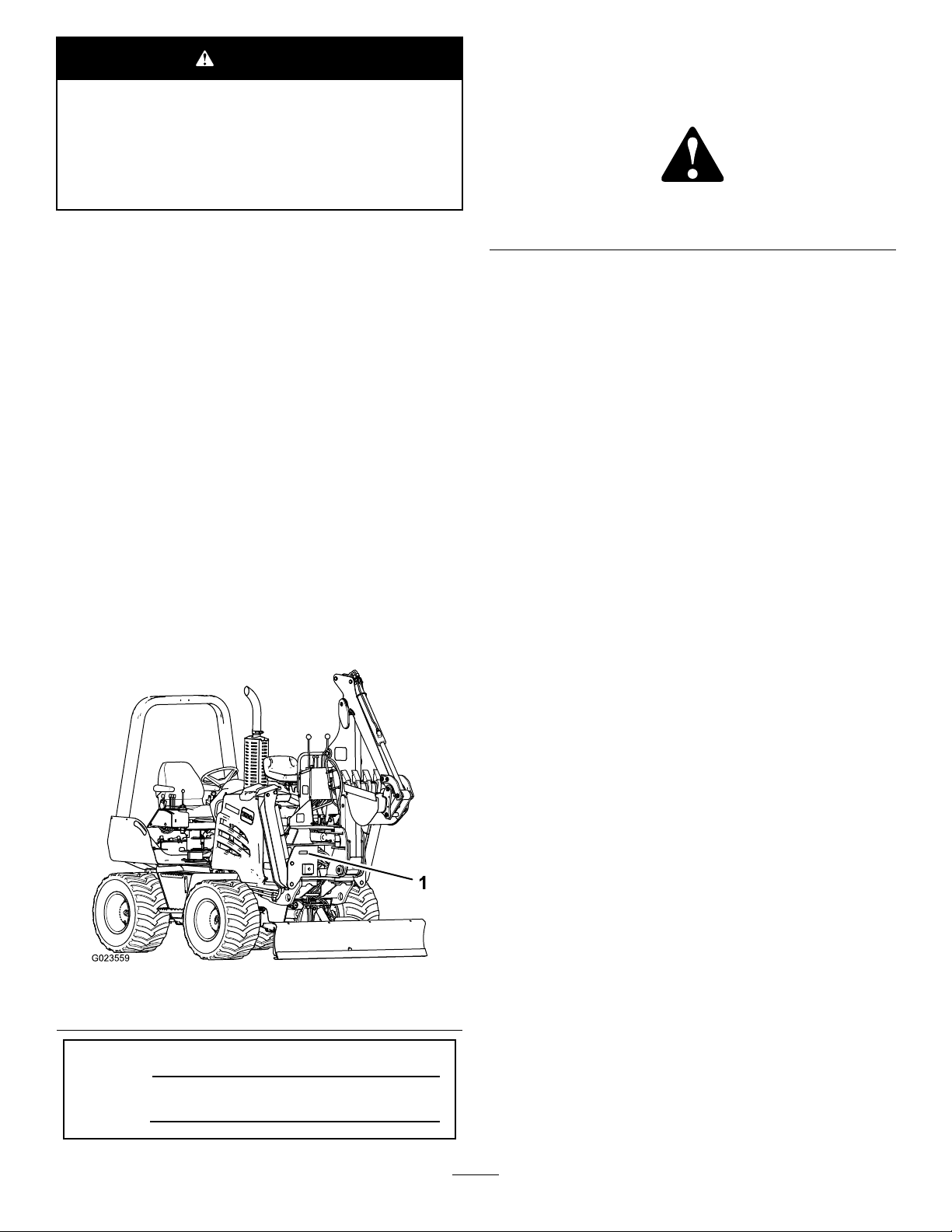
numbersofyourproductready.Figure1illustratesthe
locationofthemodelandserialnumbersontheproduct.
Writethenumbersinthespaceprovided.
Figure1
1.Locationofthemodelandserialnumberplate
ModelNo.
SerialNo.
©2014—TheToro®Company
8111LyndaleAvenueSouth
Bloomington,MN55420
Contactusatwww.Toro.com.
2
PrintedintheUSA
AllRightsReserved
Page 3

Contents
Safety...........................................................................3
SafetyandInstructionalDecals.................................5
Setup............................................................................8
1PreparingtoInstalltheAttachmentontothe
TractionUnit......................................................9
2InstallingtheBackhoeWiringHarness.....................9
3InstallingtheMountingPlatestothe
Machine............................................................11
4InstallingtheBackhoeandtheBracketsontothe
Machine............................................................11
5InstallingtheWalkwaytotheMachine.....................13
6InstallingtheHandRailandtheSeat.......................15
7InstallingtheStabilizers........................................15
8InstallingtheStabilizerActuatorsand
Hoses................................................................16
9InstallingtheHydraulicPressureandReturn
Hoses................................................................18
10RoutingandConnectingtheWiringHarness
ontotheBackhoe................................................19
11InstallingtheE-StopSwitch.................................21
12InstallingtheControlsCoverandthe
Panels...............................................................22
13BleedingtheHydraulicSystem.............................23
14TestingtheOperator-PresenceSwitchandthe
E-StopSwitch....................................................26
15LubricatingtheStabilizers....................................27
ProductOverview.........................................................27
Controls...............................................................27
BoomControls...................................................27
DipperandBucketControls.................................28
Swing-LockPedalandBoom-LockHandle.............28
Specications........................................................29
Operation....................................................................30
UsingtheStabilizers................................................30
UsingtheBoomandSwingLocks.............................31
PreparingtoUsetheBackhoe..................................33
ControllingtheBackhoe..........................................34
DiggingwiththeBackhoe........................................35
MovingtheBackhoeandtheMachine.......................36
TransportingtheMachine........................................36
OperatingTips......................................................37
Maintenance.................................................................38
LubricatingtheBackhoe..........................................38
RaisingandLoweringtheSeat..................................39
Storage........................................................................40
Safety
DANGER
Theremaybeburiedpower,gas,and/ortelephone
linesintheworkarea.Anelectricshockoran
explosionmayoccurifyoudigintoautilityline.
Havethepropertyorworkareamarkedforburied
linesanddonotdiginmarkedareas.Contactyour
localmarkingserviceorutilitycompanytohavethe
propertymarked(forexample,intheUnitedStates,
call811forthenationwidemarkingservice).
WARNING
Whengoingupordownhill,themachinecould
overturniftheheavyendistowardthedownhill
side.Someonemaybepinnedorseriouslyinjured
bythemachineifitoverturns.
Operateupanddownslopeswiththeheavyendof
themachineuphill.Anattachedbackhoewillmake
thefrontendheavy.
WARNING
Lightningcancausesevereinjuryordeath.
Iflightningisseenorthunderisheardinthearea,
donotoperatethemachine;seekshelter.
CAUTION
Hydraulicuidescapingunderpressurecan
penetrateskinandcauseinjury.Fluidinjectedinto
theskinmustbesurgicallyremovedwithinafew
hoursbyadoctorfamiliarwiththisformofinjury;
otherwise,gangrenemayresult.
•Keepyourbodyandhandsawayfrompin-hole
leaksornozzlesthatejecthigh-pressure
hydraulicuid.
•Usecardboardorpapertondhydraulicleaks;
neveruseyourhands.
3
Page 4

CAUTION
Hydraulicttings,hydrauliclines/valves,and
hydraulicuidmaybehotandcanburnyouifyou
touchthem.
•Weargloveswhenmaintaininghydraulic
components.
•Allowthetractionunitandtrenchertocool
beforetouchinghydrauliccomponents.
•Donottouchhydraulicuidspills.
4
Page 5
SafetyandInstructionalDecals
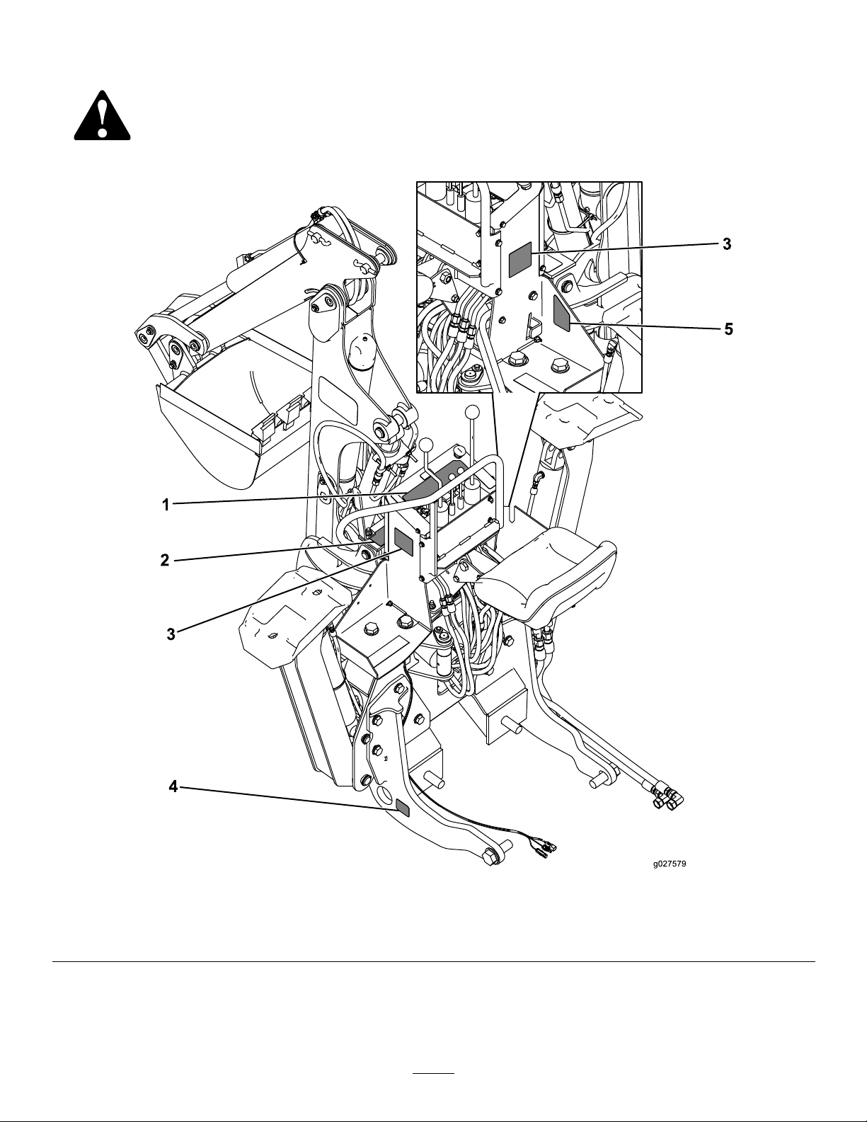
Safetydecalsandinstructionsareeasilyvisibletotheoperatorandarelocatednearanyareaofpotential
danger.Replaceanydecalthatisdamagedorlost.
Figure3
1.Decal125-84744.Decal125-6694
2.Decal125-84765.Decal125-8477
3.Decal125-6690
5
Page 6
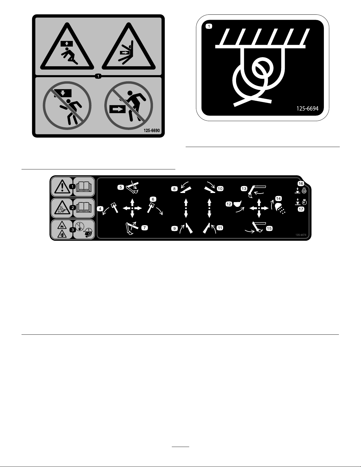
125-6694
125-6690
1.Tie-downpoint
1.Wholebodycrushinghazard—keepawayfromthemachine
wheninoperation.
125-8474
1.Warning—readtheOperator’sManual.
2.Tipping/crushinghazard—readtheOperator’sManual.
3.Explosionhazard;electricshockhazard—donotdiguntilyou
havecalledlocalutilities.
4.Movethebackhoeboomtotheleft.13.Movethebackhoearmforward.
5.Lowerthebackhoeboom.14.Dumpthebucket.
6.Movethebackhoeboomtotheright.15.Movethebackhoearmrearward.
7.Raisethebackhoeboom.
8.Lowertheleftstabilizer.17.Starttheengine.
9.Raisetheleftstabilizer.
10.Lowertherightstabilizer.
11.Raisetherightstabilizer .
12.Raisethebucket.
16.Stoptheengine.
6
Page 7
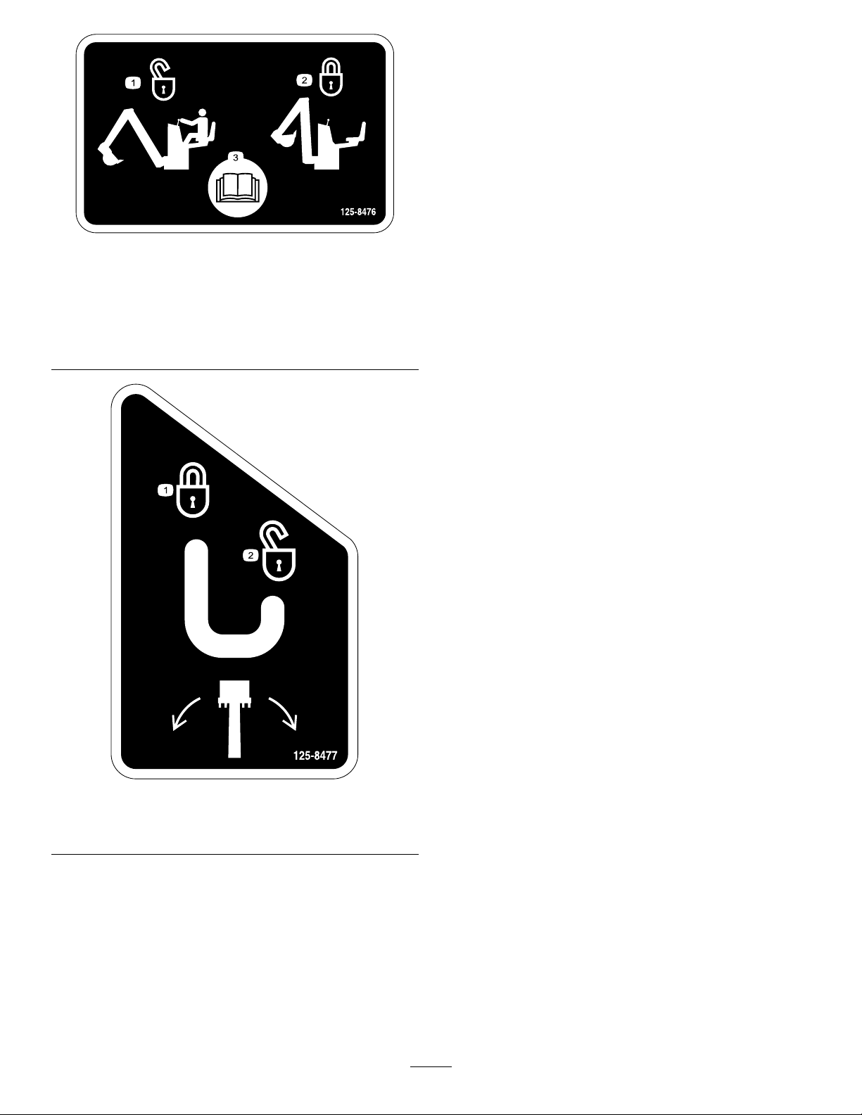
125-8476
1.Unlocktheboomonly
whenintheoperating
position.
2.Locktheboombefore
leavingtheoperating
position.
3.ReadtheOperator’s
Manual.
1.Lockthebackhoeboom
position.
125-8477
2.Unlockthebackhoeboom
position.
7
Page 8

Setup
LooseParts
Usethechartbelowtoverifythatallpartshavebeenshipped.
ProcedureDescription
1
2
3
4
5
6
7
8
Nopartsrequired
Backhoewiringharness1
Cabletie
Leftmountingplate
Rightmountingplate1
Bolt(1-1/4x3-1/2inch)
Washer(1-1/4inch)
Bracket,walkwaysupport1
Bracket,hydraulictube1
Bolt(3/4x2inch)
Bolt(3/4x2-1/2inch)
Bolt(3/4x2-3/4inch)
Washer(3/4inch)
Locknut(3/4inch)
Walkway1
Pivotbracket1
Cable
Pin1
Greasetting
Bolt(12x40mm)
Locknut(12mm)
Bolt(3/8x1inch)
Washer(3/8inch)
Locknut(3/8inch)
Washer(13/16inch)
Handrail1
Seat
Flangebolts(8x25mm)
Flangenuts(8mm)
Bolts(5/16x7/8inch)
Lockwasher(5/16inch)
Stabilizer
Pin(1-1/2x8inch)
Snapring(1-1/4inch)
Cylinder
Pin(1-1/4x8inch)
Bushing4
Pin(1-1/4x6inch)
Washer(1-3/8inch)
Snapring(1-1/8inch)
90°hydraulictting(3/8inch)
Cabletie
Qty.
14
14
12
Use
–
2
1
4
4
8
4
2
1
1
3
3
1
2
1
1
1
2
2
4
4
2
2
4
2
2
2
8
2
4
Preparetoinstalltheattachmentonto
thetractionunit.
Installthebackhoewiringharness.
Installthemountingplatestothe
machine.
Installthebackhoeandthebrackets
ontothemachine.
Installthewalkway.
Installthehandrailandtheseat.
Installthestabilizers.
Installthestabilizeractuatorsand
hoses.
8
Page 9

ProcedureDescription
9
10
Clamp
Bolt(3/8x1inch)
Washer(3/8inch)
Locknut(3/8inch)
Hose(3/4x40-1/2inch)
90°hydraulictting(3/4inch)
Nopartsrequired
Qty.
Use
2
1
2
1
2
2
–
Installthehydraulic-pressureand
hydraulic-returnhoses.
Routeandconnectthebackhoewiring
harness.
11
12
13
14
15
Important:Ensurethatthereisadequatespacetomove
thestabilizersandthebackhoearmtofullextension
andthatthemachineandtheattachmentsareclearof
obstructions.
Note:Forillustrationsoftheattachmentinstalledonthe
tractionunit,referto(page).
E-stopswitch1InstalltheE-stopswitch.
Nopartsrequired
Nopartsrequired
Nopartsrequired
Nopartsrequired
1
PreparingtoInstallthe
–
–
–
–
Installthecontrolscoverandthepanels.
Bleedthehydraulicsystem.
Testtheoperator-presenceswitchand
theE-stopswitch.
Lubricatethestabilizers.
2
InstallingtheBackhoeWiring Harness
Partsneededforthisprocedure:
1Backhoewiringharness
2
Cabletie
AttachmentontotheTraction
Unit
NoPartsRequired
Procedure
1.Parkthemachineonalevelsurface.
2.Lowertheattachment(s)totheground.
3.Turnofftheengineandremovetheignitionkey .
ConnectingtheBackhoeWiring
HarnesstotheMachine
1.Removetheleft-andright-sidepanelsandthenose
panel;refertothetractionunitOperator’sManual.
2.RotatethebatterydisconnecttotheOffposition;refer
tothetractionunitOperator’sManual.
3.Onthebackhoewiring-harness,locatethebranchof
theharnessthathasa1-pinconnector,a1-socket
connector,anda2-pinconnector(Figure4).
9
Page 10
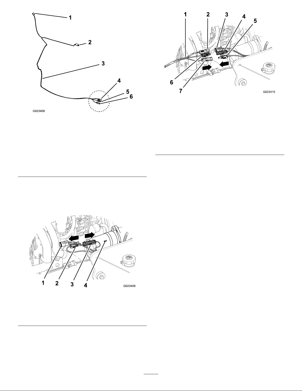
Figure6
Figure4
1.Forkedterminal(E-stop
switch)
2.Two-socketconnector
(operator-presence
switch)
3.Backhoe-wiringharness
4.Two-pinconnector
(machineharness
connection)
5.One-socketconnector
(machineharness
connection)
6.One-pinconnector
(machineharness
connection)
4.Gototheleftsideoftheenginecompartment,locate
thebranchofthemachinewiringharness(nextto
thestarter)thathasthe1-socketconnectorandthe
1-pinconnector(connectedtogether),andthe2-socket
connector(Figure5).
1.Backhoe-wiringharness
2.Two-pinconnector
(backhoeharness,E-stop)
3.Two-socketconnector
(machineharness,E-stop)
4.One-pinconnector
(machineharness,E-stop)
5.One-socketconnector
(machineharness,E-stop)
6.One-socketconnector
(backhoeharness,E-stop)
7.One-pinconnector
(backhoeharness,E-stop)
7.Connectthe1-socketconnectorofthebackhoewiring
harnesstothe1-pinconnectorofthemachinewiring
harness(Figure6).
8.Connectthe2-socketconnectorofthebackhoewiring
harnesstothe2-pinconnectorofthemachinewiring
harness(Figure6).
RoutingtheBackhoeWiringHarness
ontheMachine
1.Routethebackhoewiringharnessforward,alongthe
framerailandbelowthetopangeoftherail.
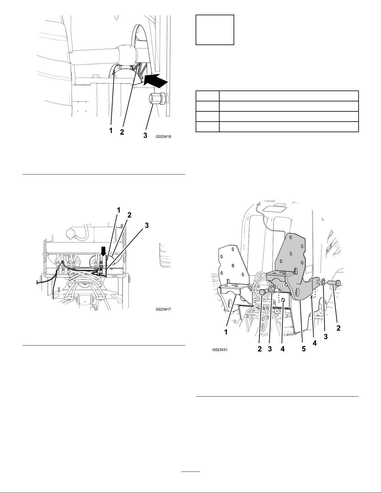
2.Routethewiringharnessovertheforwardaxleand
throughtheleftholeinthebulkheadplate(Figure7).
Figure5
1.Two-socketconnector
(operator-presence
switch)
2.Socketconnector(E-stop)4.Starter
3.Pinconnector(E-stop)
5.Separatethe1-socketconnectorandthe1-pin
connector(Figure4).
6.Connectthe1-pinconnectorofthebackhoewiring
harnesstothe1-socketconnectorofthemachine
wiringharness(Figure6).
Note:Routetheharnessinboardofthelefttilt
cylinderforthebackllblade.
10
Page 11
3
InstallingtheMountingPlates totheMachine
Partsneededforthisprocedure:
1
Leftmountingplate
1Rightmountingplate
4
Bolt(1-1/4x3-1/2inch)
4
Washer(1-1/4inch)
Figure7
1.Bulkheadplate3.Engine-oildraincap
2.Backhoewiringharness
3.Routethewiringharnessupthroughthehorizontal
accessholeinthepivotplateforthebackllblade,
whichislocatedinfrontoftheradiator(Figure8).
Figure8
Procedure
Note:Theweightofeachmountingplateweightis40.4kg
(89lb).
1.Aligntheleftandrightmountingplatestotheir
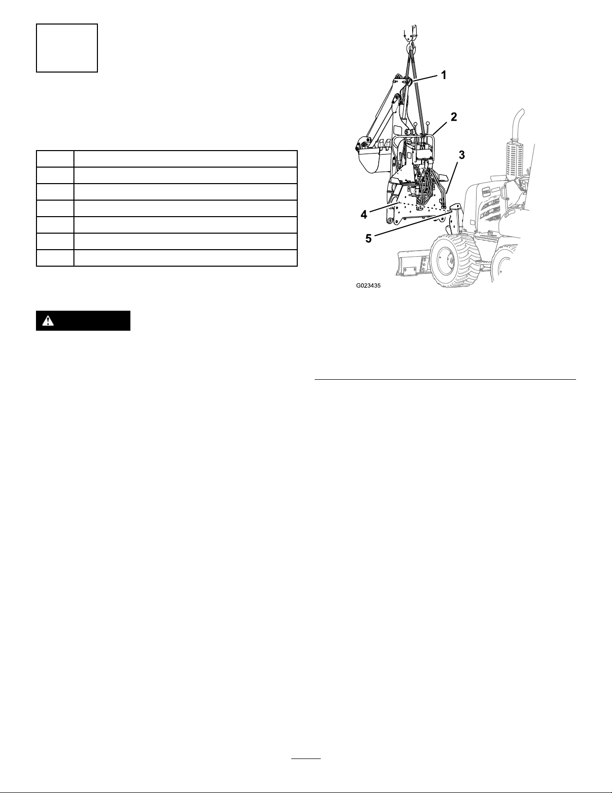
respectivefrontattachmentmountingpointsonthe
frameofthemachine(Figure9).
1.Backhoewiringharness3.Hydraulicbulkheadplate
2.Accesshole
4.Routethewiringharnessforwardthroughthehydraulic
bulkheadplateandthenforward(Figure8).
5.Installthenosepanelandtheleftandrightsidepanels;
refertothetractionunitOperator’sManual.
Note:Ensurethatthebackhoewiringharnessis
locatedunderthebottomofthenosepanelandin
frontofthepanel.
6.Laythebackhoewiringharnessoverthefrontandtop
ofthenosepanel,andtemporarilysecuretheharness
ontothepanelwithapieceofadhesivetape.
Figure9
1.Rightmountingplate4.Mountingpoint
2.Bolt(1-1/4x3-1/2inch)5.Leftmountingplate
3.Washer(1-1/4inch)
2.Attacheachmountingplatetothemachinewith2bolts
(1-1/4x3-1/2inch)and2washers(1-1/4inch),and
tightenthefastenersbyhand(Figure9).
Note:Youwilltorquetheboltsthatsecurethe
mountingplatestothemachineinstep9of4Installing
theBackhoeandtheBracketsontotheMachine(page
11).
11
Page 12
4
InstallingtheBackhoeandthe
BracketsontotheMachine
Partsneededforthisprocedure:
1Bracket,walkwaysupport
1Bracket,hydraulictube
8
Bolt(3/4x2inch)
4
Bolt(3/4x2-1/2inch)
2
Bolt(3/4x2-3/4inch)
14
Washer(3/4inch)
14
Locknut(3/4inch)
Procedure
WARNING
Liftingheavymachinesandattachmentsimproperly
couldresultinseriousinjuryorevendeath.
Whenliftingheavymachinesandattachments,use
liftingequipment,suchaschainsandstraps,thatis
ratedfortheweightoftheequipment.
Note:Theweightoftheattachmentis606.6kg(1,337lb).
1.Attachtheliftingequipmenttothehandlebarandthe
dipperactuatormountingpoint(Figure10).
Figure10
1.Dipper-actuatormounting
point
2.Handlebar5.Mounting-platehole
3.Pressureandreturn
hydraulictubes
2.Aligntheholesinthebackplateofthebackhoewith
themountingholesinthe2mountingplates(Figure
10).
Note:Usecarewhenaligningthehydraulic-pressure
andhydraulic-returntubesrearwardoftheright
mountingplateofthebackhoe.
3.Aligntheholesinthewalkway-supportbracketwith
holesatthebacksideoftheleftmountingplate(Figure
11).
4.Back-platemountinghole
12
Page 13
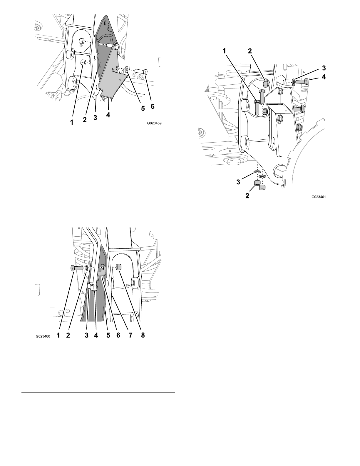
Figure11
7.Installthe7horizontalbolts(3/4x2inch),the7
washers,andthe7locknutsintheremainingholesat
thebacksideoftherightandleftmountingplates,and
tightenthesefastenersbyhand(Figure13).
1.Locknut(3/4inch)
2.Mountingplate
3.Backplateofthebackhoe6.Bolt(3/4x2-3/4inch)
4.Walkway-supportbracket
5.Washer(3/4inch)
4.Insertthe2bolts(3/4x2-3/4inch)throughthe2
washers,thewalkway-supportbracket,themounting
plate,andthebackhoeframe;install2locknuts(3/4
inch)onthebolts;andtightenthelocknutsbyhand
(Figure11).
5.Aligntheholeinthehydraulic-tubebracketwithhole
atthebacksideoftherightmountingplate(Figure12).
Figure13
1.Bolt(3/4x2-1/2inch)3.Washer(3/4inch)
2.Locknut(3/4inch)4.Bolt(3/4x2inch)
8.Insertthe4verticalbolts(3/4x2-1/2inch)through
theholesinthelowerpivotplate(insidethepocketsfor
thestabilizermountingpoints),andsecurethemwith4
washersand4locknutsasshowninFigure13.
9.Torquethe4bolts(1-1/4x3-1/4inch)thatsecurethe
mountingplatestothemachineto915to1119N-m
(675to825ft-lb).
10.Torquethe10horizontalbolts(3/4inchdiameter)that
securethebackhoetothemachineto525to655N-m
(387to483ft-lb).
Figure12
1.Bolt(3/4x2inch)
2.Washer(3/4inch)
3.Hydraulic-pressuretube
4.Hydraulic-returntube
5.Mountingplate
6.Hydraulic-tubesupport
bracket
7.Backplateofthebackhoe
8.Locknut(3/4inch)
6.Insertthebolt(3/4x2inch)andwasher(3/4inch)
throughthehydraulic-tubesupportbracket,the
mountingplate,andthebackhoeframe;installa
locknutonthebolt;andtightenthelocknutbyhand
(Figure12).
11.Torquethe4verticalbolts(3/4x2-1/2inch)that
securethebackhoetothemachineto525to655N-m
(387to483ft-lb).
13
Page 14
5
InstallingtheWalkwaytothe
Machine
Partsneededforthisprocedure:
1Walkway
1Pivotbracket
1
Cable
1Pin
1
Greasetting
3
Bolt(12x40mm)
3
Locknut(12mm)
1
Bolt(3/8x1inch)
2
Washer(3/8inch)
1
Locknut(3/8inch)
1
Washer(13/16inch)
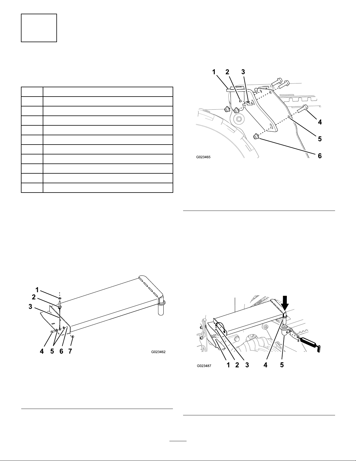
InstallingtheLockingPinandCableon
theWalkway
1.Securethecabletotheoutboardholeontheforward,
verticalangeofthewalkwaywithabolt(3/8x1
inch),2washers(3/8inch),andalocknut(3/8inch)as
showninFigure14.
Note:Ensurethatthecableisverticallyalignedtothe
angeofthewalkway .
3.Slipthewasher(13/16inch)overtheendofthelocking
pinandpastthespring-loadedball(Figure14).
InstallingtheWalkwayPivotBracket
1.Threadthegreasettingintotheholeinthecylindrical
partofthepivotbracket(Figure15).
Figure15
1.Pivotbracket
2.Holeforthegreasetting5.Forwardangeofthefuel
3.Greasetting6.Flangelocknut(12mm)
4.Flange-headbolt(12x40
mm)
tank
2.Aligntheholesinthepivotbracketwiththeholesin
theforwardangeofthefueltank(Figure15).
3.Looselysecurethebrackettothefueltankwith3bolts
(12x40mm)and3locknuts(12mm)asshownin
Figure15.
InstallingtheWalkway
Figure14
1.Washer(13/16inch)5.Washer(3/8inch)
2.Lockingpin
3.Cable
4.Bolt(3/8x1inch)
6.Verticalangeofthe
walkway
7.Locknut
2.Threadthesplitringofthelockingpinthroughthe
loopinthecable(Figure14).
1.Alignthepivotpinofthewalkwaywiththeholeinthe
pivotbracketcylinder(Figure16).
Figure16
1.Walkwaysupportbracket4.Pivotpin
2.Horizontalangeofthe
walkway
3.Lockingpin
5.Pivotbracketcylinder
2.Fullyseatthepivotpinintothecylinder(Figure16).
14
Page 15
3.Applygreasetothegreasetting.
Note:Usealithium-basegrease.
Note:Cleanupanyexcessgreaseonthewalkway
pivotwitharag.
4.Rotatethewalkwayclockwiseuntiltheholeinthe
forward,horizontalangeofthewalkwayisaligned
withtheholeinthehorizontalangeofthewalkway
supportbracket(Figure16).
Note:Raiseorlowerthepivotbracketasneededto
alignthewalkwaywiththewalkwaysupportbracket.
5.Tightentheboltsandnutsthatsecurethepivotsupport
brackettothefuel-tankange(Figure16).
6.Securethewalkwaytothewalkwaysupportbracket
withthelockingpin(Figure16).
6
InstallingtheHandRailand theSeat
Partsneededforthisprocedure:
1Handrail
1
Seat
2
Flangebolts(8x25mm)
2
Flangenuts(8mm)
4
Bolts(5/16x7/8inch)
4
Lockwasher(5/16inch)
Procedure
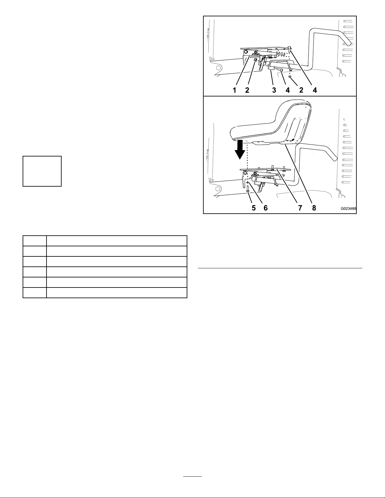
1.Aligntheholesinthebracketforthehandrailwiththe
holesintheseatpost(Figure17).
Figure17
1.Seatpost5.Bolt—5/16x7/8inch(4)
2.Flangenut(8mm)6.Lockwasher(5/16inch)
3.Handrail
4.Flangebolt(8x25mm)8.Seat
2.Securethehandrailtothebracketoftheseatpostwith
2angebolts(8x25mm)and2angenuts(Figure17).
3.Aligntheholesofthebottomoftheseatwiththeholes
inthebracketontheseatarm(Figure17).
4.Applymedium-grade(serviceremovable)
thread-lockingcompoundtothe4bolts(5/16x7/8
inch)fromlooseparts.
5.Securetheseattothesupportoftheseatpostwith4
bolts(5/16x7/8inch)and4lockwashers;referto
Figure17.
7.Seatsupport
15
Page 16
7
InstallingtheStabilizers
Partsneededforthisprocedure:
2
Stabilizer
2
Pin(1-1/2x8inch)
4
Snapring(1-1/4inch)
Procedure
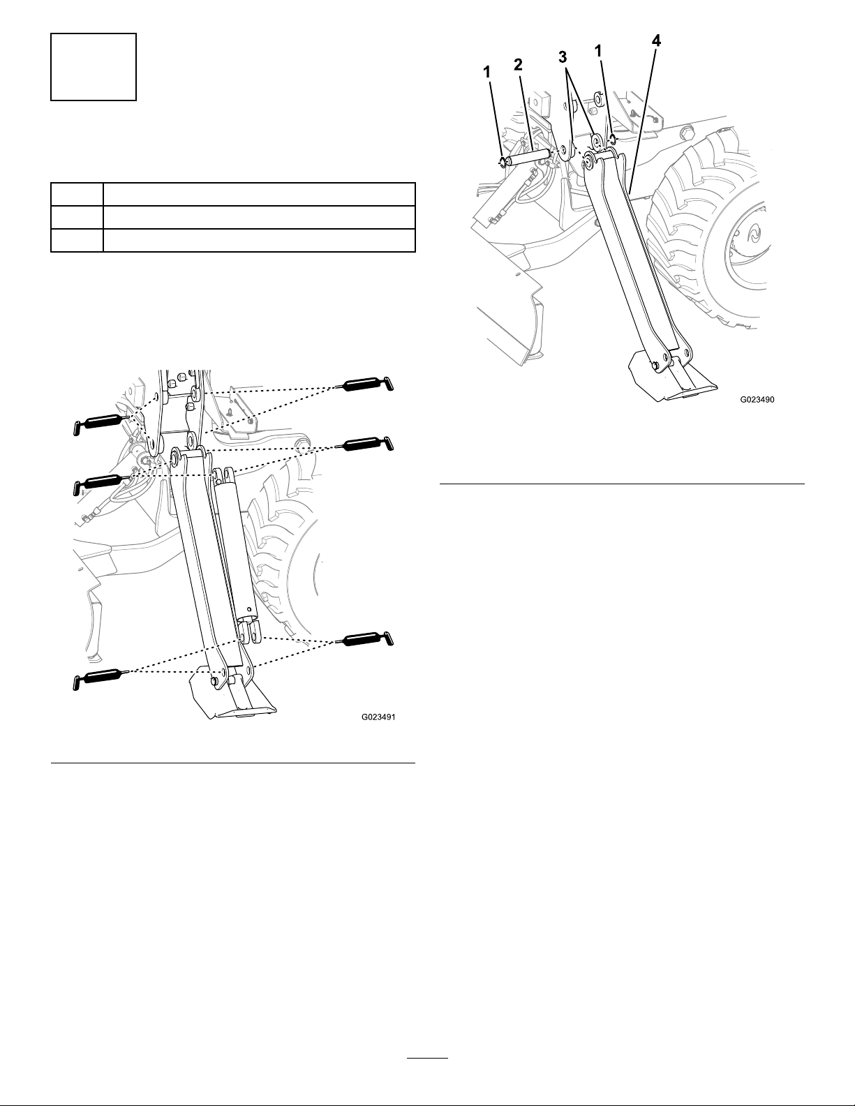
1.Lubricatetheinsidediameterofthe1-1/4-inchand
1-1/2-inchbushingsofthestabilizerswithgreaseatthe
frontandbackplatesofthebackhoe(Figure18).
Figure19
Figure18
2.Lubricatetheinsidediameterofthe1-1/4-inchand
1-1/2-inchpivotpointwithgreaseatthefrontand
backsideplatesofthestabilizers(Figure18).
3.Lubricatetheinsidediameterofthe1-1/4-inchholes
withgreaseatbothendsofthehydraulicactuators
(Figure18).
1.Snapring(1-1/4inch)
2.Pin(1-1/2x8inch)4.Stabilizer
5.Insertapin(1-1/2x8inch)throughtheholesinthe
backhoeframeandthestabilizer(Figure19).
6.Securethepinwith2snaprings(1-1/4inch)asshown
inFigure19.
7.Repeatsteps4through6toinstalltheotherstabilizer
totheothersideofthebackhoeframe.
3.Lowerbushings
4.Alignthepivotpointatthefrontandbacksideplates
ofoneofthestabilizerstothelowerbushingsinthe
backhoeframe(Figure19).
16
Page 17
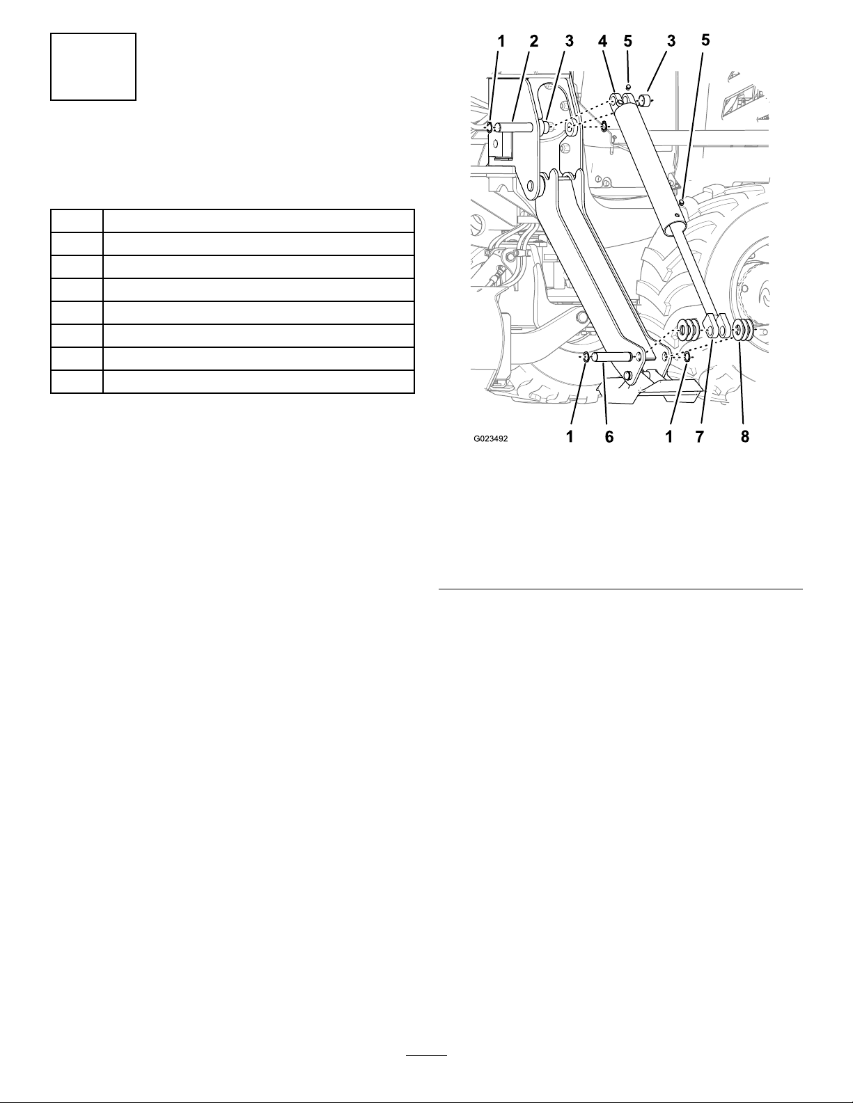
8
InstallingtheStabilizer
ActuatorsandHoses
Partsneededforthisprocedure:
2
Cylinder
2
Pin(1-1/4x8inch)
4Bushing
2
Pin(1-1/4x6inch)
12
Washer(1-3/8inch)
8
Snapring(1-1/8inch)
2
90°hydraulictting(3/8inch)
4
Cabletie
InstallingtheHydraulicActuators
Note:Theweightofeachcylinderis31.6kg(69.6lb).
1.Attachthehydraulicactuatortothebackhoeasfollows:
A.Ensurethatthestabilizerisrestingonthefoot
pad.
B.Insertapin(1-1/4x8inch)throughtheupper
bushingintheforwardplateofthebackhoeframe
(Figure20).
Note:Allowthepintoextendabout25mm(1
inch)beyondthebushing.
Figure20
1.Snapring(1-1/8inch)
2.Pin(1-1/4x8inch)partially
insertedintotheforward
plate
3.Bushing
4.Cylindertting8.Washer(1-3/8inch)
C.Slipabushing(fromthekit)overtheshort
segmentofthepin(Figure20).
D.Alignthemountingholesofthecylindertting
(nearthehydraulicport)ofthehydraulicactuator
tothepin(1-1/4x8inch),andmovethepin
throughthemountingholes(Figure20).
5.Plug
6.Pin(1-1/4x6inch)
7.Pistontting
Note:Ensurethatthehydraulicportsofthe
cylinderarepositionedupward.
E.Continueinsertingthepinthroughthecylinder
tting(Figure20).
Note:Theactuatorshouldbepartiallysupported
bythepin.
F.Alignabushing(fromthekit)betweentherear
mountingholeofthecylinderttingandthe
bushinginthebackplatesofthebackhoe(Figure
20).
G.Continueinsertingthepinthroughthebushing
andthebushinginthebackplatesofthebackhoe
(Figure20).
2.Attachthehydraulicactuatortothestabilizerasfollows:
A.Insertapin(1-1/4x6inch)throughthepivot
pointofthestabilizer(Figure20).
17
Page 18
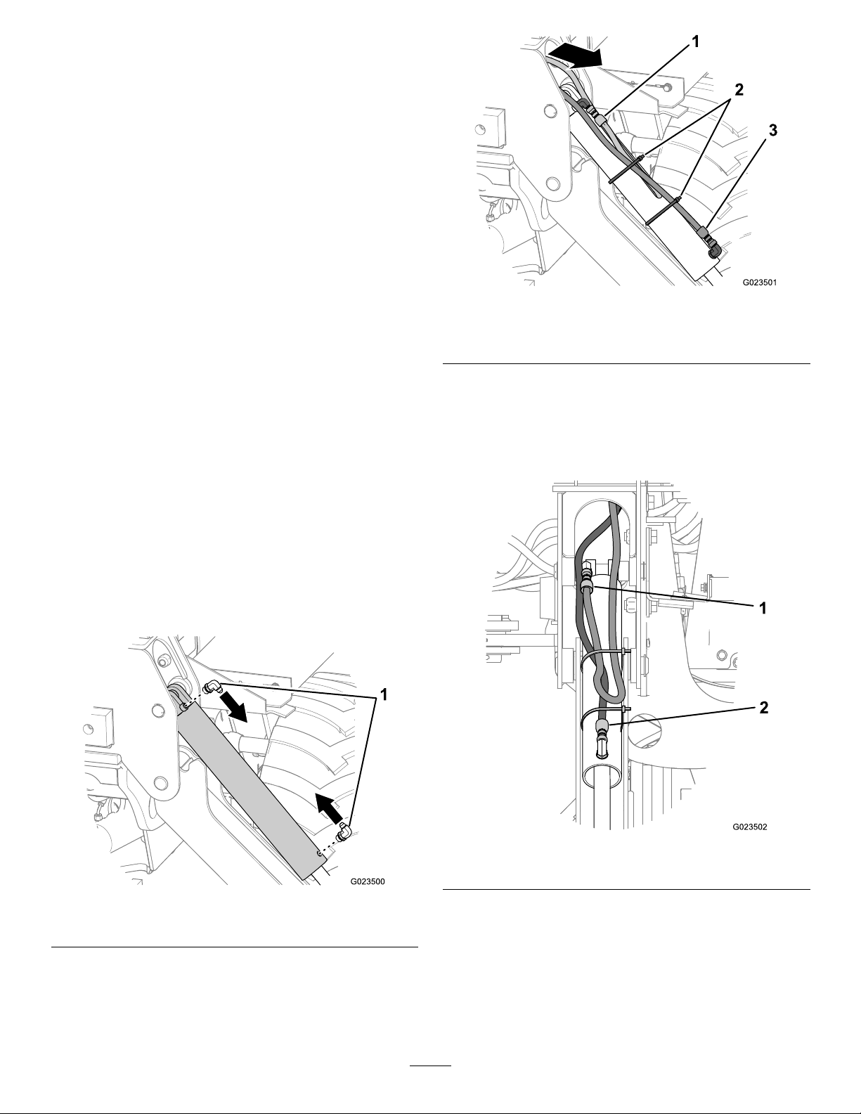
Note:Allowthepintoextendslightlythrough
thepivotpoint.
B.Slipa3washers(1-3/8inch)overtheshort
segmentofthepin(Figure20).
C.Removetheplugsfromtheportsofthecylinder
andcovertheholeswithacleanrag(Figure20).
D.Extendthepistonttingofthecylindertothe32
mm(1-1/4inch)pivotpointofthestabilizer.
Note:Residualhydraulicuidmayejectfrom
thecylinderports.
E.Continueinsertingthepinthroughthepiston
ttingofthecylinder(Figure20).
F.Align3washers(1-3/8inch)betweenthepiston
ttingofthecylinderandtheotherpivotpointof
thestabilizer(Figure20).
G.Continueinsertingthepinthroughthewashers
andthepivotpointofthestabilizer(Figure20).
3.Securethe2pin(1-1/4x8inch)with4snaprings
(1-1/8inch)asshowninFigure20.
4.Repeatsteps1through3forthehydrauliccylinderfor
theotherstabilizer.
Figure22
1.Extendhose3.Retracthose
2.Cableties
3.Routetheextendandretracthosestothettingsthat
youinstalledinstep1.
4.Connecttheextendhosetothettingintheextend
port,andconnecttheretracthosetothettinginthe
retractport(Figure23).
AttachingtheHosestotheHydraulic
Actuators
1.Installthe2hydraulicttings(3/8inch,90°)intothe
hydraulicportsoftheactuator(Figure21).
Note:Ensurethatthettingspointtowardeachother
(Figure21).
Figure21
1.90°hydraulicttings
2.Removethehosesfrominsidethepocketsforthe
stabilizermountingpoint(Figure22).
Figure23
1.Extendhose2.Retracthose
5.Securethehydraulichosestothecylinderofthe
actuatorwithcabletiesasshowninFigure22and
Figure23.
6.Repeatsteps1through5fortheothersideofthe
backhoe.
18
Page 19
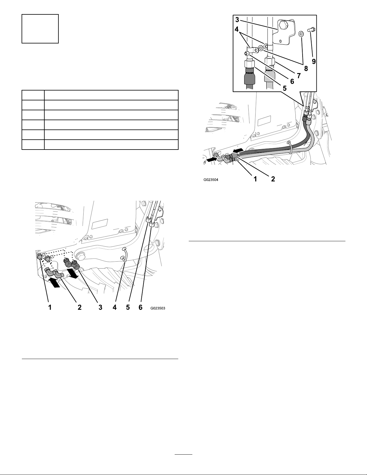
9
InstallingtheHydraulic
PressureandReturnHoses
Partsneededforthisprocedure:
2
Clamp
1
Bolt(3/8x1inch)
2
Washer(3/8inch)
1
Locknut(3/8inch)
2
Hose(3/4x40-1/2inch)
2
90°hydraulictting(3/4inch)
Procedure
1.Placeadrainpanunderthehydraulic-shunttting
thatconnectsthebulkheadttingsforthehydraulic
pressureandreturncircuitsofthemachine(Figure24).
Figure25
1.Hydraulic-pressurehose
2.Hydraulic-returnhose7.Hydraulic-returntube
3.Hydraulic-tubebracket
4.Clamps9.Bolt(3/8x1inch)
5.Hydraulic-pressuretube
6.Locknut(3/8inch)
8.Washers(3/8inch)
Figure24
1.Bulkheadtting
2.90°hydraulictting(3/4
inch)
3.Shunttting
2.Removetheshuntttingandlooselyinstallthe2
hydraulicttings(3/4inch,90°)ontothebulkhead
ttings(Figure24).
Note:Retaintheshuntttingsothatyoucaninstallit
whenyouremovethebackhoe.
3.Routethe2hydraulichosesthroughthehosesupport
ontherightbackhoemountingplateasshownin
Figure25.
4.Hosesupport
5.Hydraulic-pressuretube
6.Hydraulic-returntube
4.Connectandtightenthe2hosestothehydraulic
pressureandsupplytubesthatalignverticallyrearward
oftheright-mountingplateforthebackhoe(Figure25).
5.Assemblethe2tubeclampstothehydraulicpressure
andsupplytubes,andsecurethemtothetubebracket
withabolt(3/8x1inch)andlocknut(3/8inch)as
showninFigure25.
6.Connectandtightenthefreeendsofthehosestothe
90°hydraulicttingthatyouinstalledinstep2.
7.Alignandtightenthe2elbowttingsatthebulkhead
ttings.
8.Tightenthettingsofthehosesatthepressuretube,
thereturntube,andthe2elbowttings.
19
Page 20
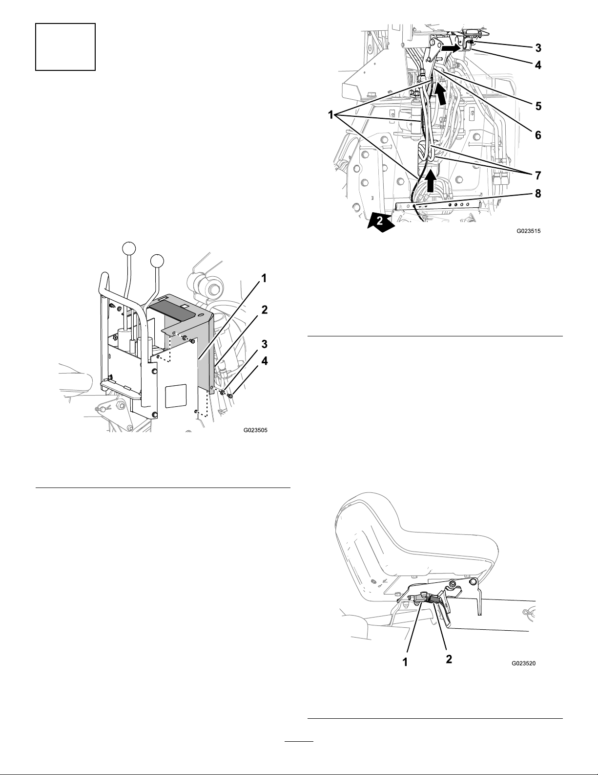
10
RoutingandConnectingthe
WiringHarnessontothe
Backhoe
NoPartsRequired
Procedure
1.Removethe4boltsand4washersthatsecurethe
controlscovertotheoperatorpedestalofthebackhoe,
andremovethecover(Figure26).
Figure27
Figure26
1.Operatorpedestal
2.Controlscover
2.Routethebackhoeharnessupwardandalongthe
2leftmosthydraulichosesatthebackplateofthe
backhoe(Figure27).
3.Washer
4.Bolt
1.Backhoewiringharness
2.Forward
3.Two-socketconnector7.Hydraulichoses
4.Seat-posttube
3.Routetheharnessupwardandbetweentheleftand
rightconsole-supportplatesoftheoperatorpedestal
(Figure27).
4.Routethebranchoftheharnesswitha2-socket
connectorthroughthetubeoftheseatpost(Figure27).
5.Connectthe2-socketconnectorofthebackhoewiring
harnesstothe2-pinconnectoroftheoperatorpresence
switch(Figure28).
Note:Ensurethatthereisenoughslackinthebranch
oftheharnessfortheoperator-presenceswitchatthe
forwardendoftheseatpost.
5.Console-supportplate
(left)
6.Console-supportplate
(right)
8.Hydraulic-bulkheadplate
1.Operator-presenceswitch
20
Figure28
2.Two-pinconnector,
backhoewiringharness
Page 21
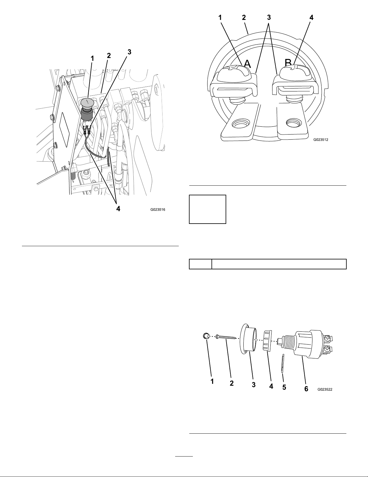
6.Routethebranchofthewiringharnesswiththe
1
3
42
G023512
G023522
1
2
3
4
5
6
2-forkedelectricalterminalsforwardofthehydraulic
manifoldandhoses,andthenrouteittotheright
(Figure28).
Figure30
Bottomview
Figure29
1.E-stopswitch3.Forkedterminals
2.Hydraulicmanifold
7.Connectthe2-forkedelectricalterminalstoterminals
AandBwiththeterminalscrewsandthesaddle
washersoftheE-stopswitch,andtightenthescrews
(Figure30).
4.Backhoe-wiringharness
1.TerminalscrewA
2.E-stopswitch4.TerminalscrewB
3.Saddlewashers
11
InstallingtheE-StopSwitch
Partsneededforthisprocedure:
1E-stopswitch
Procedure
1.DisassembletheE-stopswitchasfollows:
A.RemovethebuttoncoverfromtheE-stopbutton
().
Figure31
1.Buttoncover4.Jamnut
2.Screw5.C-clip
3.E-stopbutton6.E-stopswitch
21
Page 22
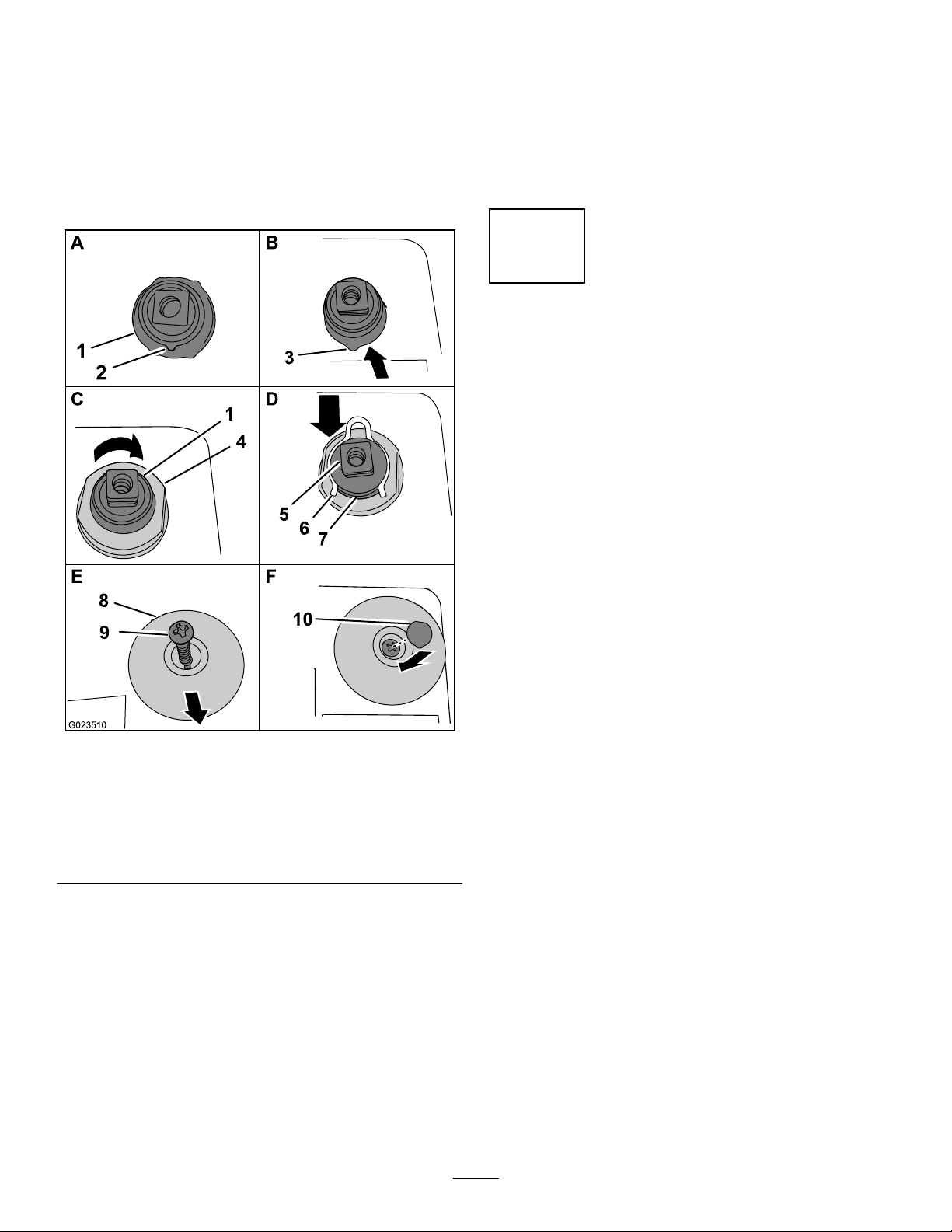
B.RemovethescrewthatsecurestheE-stopbutton
totheE-stopswitch,andremovethebutton
(Figure31).
C.RemovetheC-clipandthejamnutfromthebody
oftheE-stopswitch(Figure31).
2.InstalltheE-stopswitchasfollows:
A.Locatethealignmenttangonthebodyofthe
E-stopswitch(Figure32).
E.AlignthesquarerecessinthebackoftheE-stop
buttontothesquarettingoftheE-stopswitch.
F.SecuretheE-stopbuttontotheswitchwiththe
screw(Figure32)thatyouremovedinstep1-B.
G.Installthebuttoncover(Figure32)thatyou
removedinstep1-Aintothescrewpocketinthe
E-stopbutton.
12
InstallingtheControlsCover andthePanels
NoPartsRequired
Procedure
1.Aligntheholesofthecontrolscoverwiththeholesin
theoperatorpedestalofthebackhoe(Figure26).
Figure32
1.E-stopswitch
2.Alignmenttang
3.Notchinthehole8.E-stopbutton
4.Jamnut
5.Squaretting
B.Aligntheswitchfromtheinsideofthecontrol
coverandthroughtheholeintheupperright
corner(Figure32).
6.C-clip
7.Groove
9.Screw
10.Buttoncover
2.Addmedium-grade(serviceremovable)thread-locking
compoundtothe4boltsthatyouremovedinstep1of
10RoutingandConnectingtheWiringHarnessonto
theBackhoe(page19).
3.Securethecovertothepedestalwiththe4boltsand4
washers(Figure26)thatyouremovedinstep1of10
RoutingandConnectingtheWiringHarnessontothe
Backhoe(page19).
4.RotatethebatterydisconnecttotheOnposition;refer
tothetractionunitOperator’sManual.
5.Installtheleft-andright-sidepanelsandthenose
panel;refertothetractionunitOperator’sManual.
Note:Ensurethatthealignmenttangonthe
E-stopswitchalignswiththenotchinthehole
fortheswitch.
C.Securetheswitchtothepanelwiththejamnut
(Figure32)thatyouremovedinstep1-C.
D.InstalltheC-clip(Figure32)thatyouremoved
instep1-Cintothegrooveinthebodyofthe
E-stopswitch.
22
Page 23
13
BleedingtheHydraulicSystem
NoPartsRequired
Procedure
WARNING
Co-workersandbystandersnearthemoving
attachmentpartscomeintocontactwithan
attachmentpart,causingseriousinjuryordeath.
Beawareofwhereotherworkersareinthearea
whileyouarebleedingthehydraulicsystem,and
keepothersawayfromthearea.
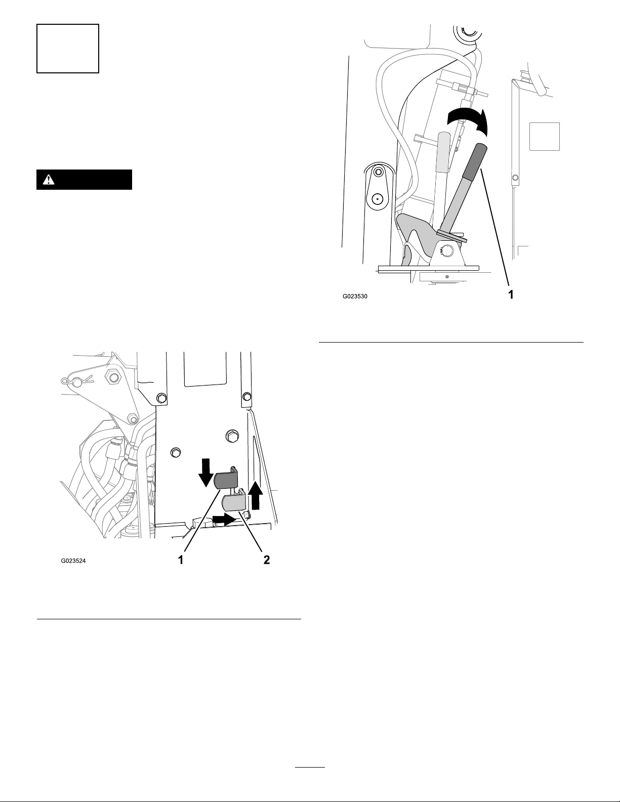
1.Iftheswinglockforthebackhoeboomisset,release
thelockbypushingtheswing-lockpedaldown,
pushingthepedalforward,andallowingthepedalto
riseupintotheforwardnotch.
Figure33
1.Swing-lockpedal(locked
position)
2.Swing-lockpedal
(unlockedposition)
Figure34
1.Boom-latchhandle
3.Carefullylowertheliftingequipmentandremoveit
fromthebackhoe.
4.Settheparkingbrakeandensurethatallthecontrols
areintheNeutralposition(theneutralindicatorlamp
isilluminated).
5.Startthemachine,andsettheenginespeedissetto
1/4throttle.
6.Movetotheoperatorseatofthebackhoe.
7.Moveeachstabilizercontrolupanddownseveral
timestomovethestabilizersthroughitsfullrangeof
movement(Figure35).
2.Iftheboomlockforthebackhoeboomisset,release
thelockbypullingtheboom-latchhandlerearward.
23
Page 24
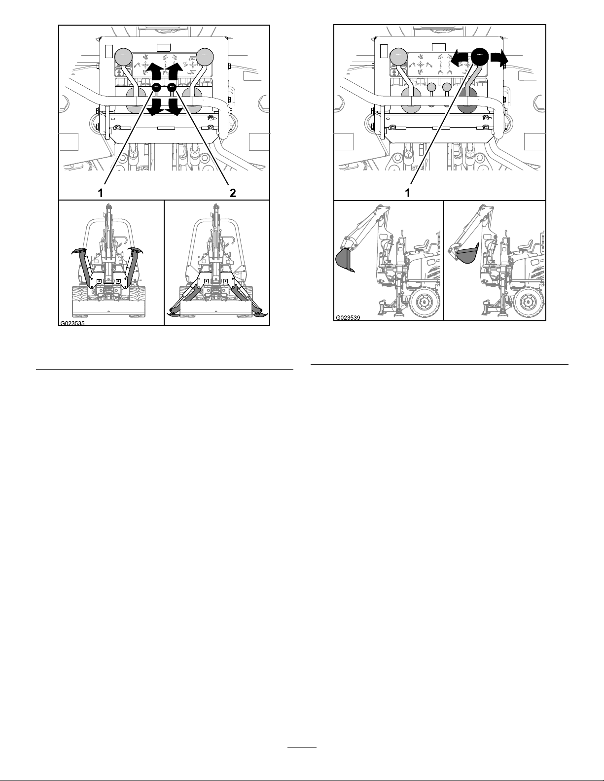
1.Left-stabilizercontrol
Figure35
2.Right-stabilizercontrol
Figure36
1.Bucketanddippercontrol(bucketmovement)
8.Movebothstabilizerstothedownposition(Figure35).
9.Movethebackhoecontrolsasfollows:
•Movethebucketcontroltocurlandextendthe
bucketseveraltimestomovethebucketthrough
itsfullrangeofmovement.
•Movethedippercontroltoextendandretractthe
dipperseveraltimestomovethedipperthroughits
fullrangeofmovement.
24
Page 25
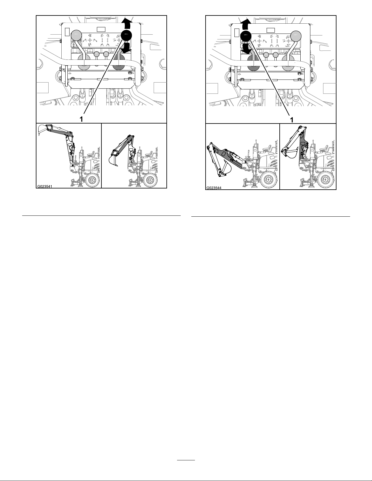
1.Bucketanddippercontrol(dippermovement)
Figure37
Figure38
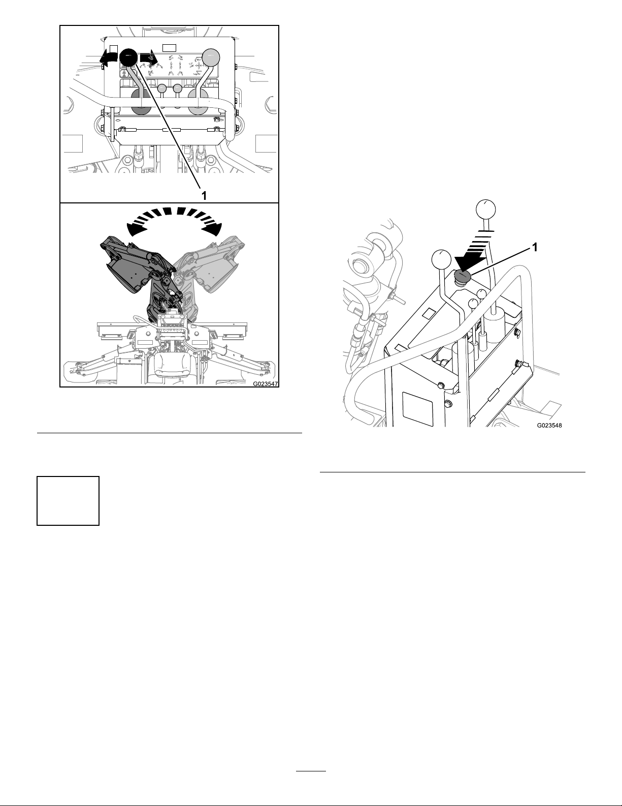
1.Boomcontrol(elevationmovement)
•Movetheboomelevationcontrolupanddown
severaltimestomovetheboomthroughitsfull
rangeofmovement.
•Movetheboomswingcontrolleftandrightseveral
timestomovetheboomthroughitsfullrangeof
movement.
25
Page 26
andthentotheright(extendor“crowdout”the
bucket);refertoFigure36.
Note:Thebucketshouldnotmove.
C.Sitinthebackhoeoperatorseat.
D.Movethebucketanddippercontroltotheleft
andthentotheright(Figure36).
Note:Thebucketshouldcurlandthenextend.
E.PresstheE-stopbutton(Figure40).
Note:Theengineofthetractionunitshould
stop.
Figure39
1.Boomcontrol(swingmovement)
10.Movetheboomtothetransportposition;refertothe
TransportingtheMachine(page36).
14
TestingtheOperator-Presence SwitchandtheE-StopSwitch
NoPartsRequired
Procedure
Important:Ifyourmachinefailsanyofthefollowing
tests,donotoperatethemachine;contactanAuthorized
ServiceDealer.
1.Atthebackhoeoperatorpanel,performthefollowing
tests:
Figure40
1.E-stopbutton
2.ReleasetheenginestopswitchbypullinguptheE-stop
button.
3.RotatethekeyswitchonthemachinetotheOff
position.
A.Standonthewalkway.
B.Movethebucketanddippercontrol(theleftmost
control)totheleft(curlor“crowdin”thebucket)
26
Page 27
15
LubricatingtheStabilizers
NoPartsRequired
Procedure
1.Raisethestabilizers.
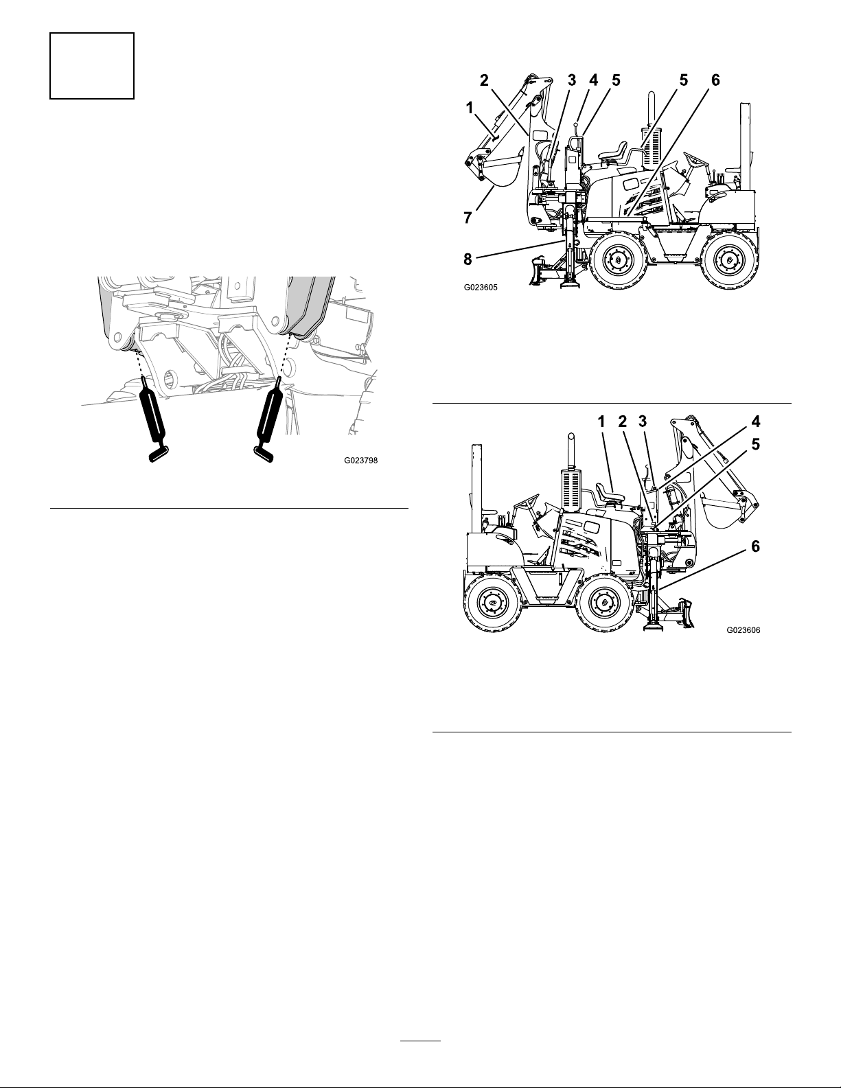
2.Cleanthegreasettings(Figure41)witharag.
ProductOverview
Figure42
1.Dipper5.Handrail
2.Boom6.Walkway
3.Boom-latchhandle7.Bucket
4.Controls8.Leftstabilizer
Figure41
3.Connectthegreaseguntothegreasettings,andapply
2or3pumpsofgreasetoeachtting.
4.Wipeupanyexcessgrease.
5.Lowerthestabilizers.
Figure43
1.Seat4.Operatorconsole
2.Swing-lockpedal
3.E-stopbutton6.Rightstabilizer
5.Foothold
Controls
BoomControls
BoomExtensionControlLever
•Movetheleverforwardtolowertheboom(Figure44).
•Movetheleverrearwardtoraisetheboom(Figure44).
27
Page 28
E-StopSwitch
Usetheremoteengineshutoffcontrolknobtostopthe
enginewhenyouareinthebackhoeoperator’sseat.
•Pushdownonthecontrolknobtostoptheengine
(Figure44).
•Pulluponthecontrolknobbeforere-startingtheengine
(Figure44).
Note:Theenginewillnotstartifthecontrolknobisnot
pulledupintheResetposition.
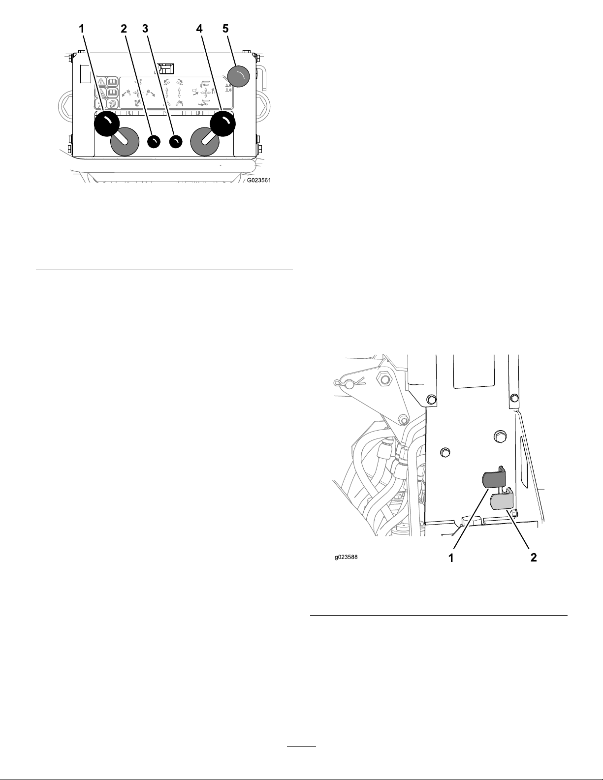
Figure44
1.Boomextensionandswing
controllever
2.Leftstabilizercontrollever
3.Rightstabilizercontrol
lever
BoomSwingControlLever
4.Dipperextensionand
bucketcontrollever
5.E-stopswitch
•Movethelevertothelefttoswingtheboomtotheleft
(Figure44).
•Movethelevertotherighttoswingtheboomtotheright
(Figure44).
StabilizerControls
•Movetheleft-stabilizerleverforwardtolowertheleft
stabilizer(Figure44).
•Movetheleft-stabilizerleverrearwardtoraisetheleft
stabilizer(Figure44).
•Movetheright-stabilizerleverforwardtolowertheright
stabilizer(Figure44).
Swing-LockPedalandBoom-Lock Handle
Swing-LockPedal
Usetheswing-lockpedaltolocktheboom,thedipper,and
thebuckettothetransport(straightforward)position(Figure
45).Usetheswing-lockpedaltounlocktheswinglockafter
transportingthemachineorbeforeoperatingthebackhoe.
•Tolocktheswinglock,movethepedaldown,rearward,
andthenup.
•Tounlocktheswinglock,movethepedaldown,forward,
andthenup.
•Movetheright-stabilizerleverrearwardtoraisetheright
stabilizer(Figure44).
DipperandBucketControls
DipperExtensionControlLever
•Movetheleverforwardtomovethedipperout(Figure
44).
•Movetheleverrearwardtomovethedipperin(Figure
44).
BucketControlLever
•Movethelevertothelefttocurl(load)thebucket(Figure
44).
•Movethelevertotherighttodump(unload)thebucket
(Figure44).
1.Swing-lockpedal(locked
28
Figure45
position)
2.Swing-lockpedal
(unlockedposition)
Page 29
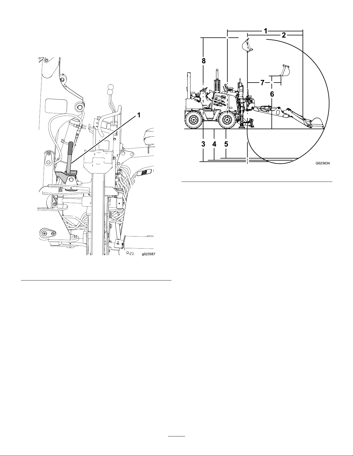
Boom-LockHandle
Usetheboom-lockhandletoreleasethelockfortheboom
andallowtheboomtomovefromthetransport(upright)
position(Figure46).Pulltheboom-lockhandlerearwardto
unlocktheboomlock.
Specications
Figure47
1.Boomlock
Figure46
1.
Reachfromcenterlineof
frontaxleofthemachine
2.
Diggingreachfromswing
pivot
3.
Diggingdepth(maximum)222cm(87in)
4.
Diggingdepth,0.6m(2foot)
atbottomtrench
5.
Diggingdepth,2.4m(8foot)
atbottomtrench
6.Loadingheight
7.
Loadingreach
8.
Overallheight(maximum)422cm(166in)
Weightofbackhoeattachment:938.5kg(2069lb)
429cm(169in)
34cm(136in)
215cm(85in)
203cm(80in)
224cm(88in)
155cm(61in)
29
Page 30
Operation
Determinetheleftandrightsidesofthemachinefromthe
normaloperatingposition.
Thebackhoecontrolsconsistsof4leversand1button.The
leftlevercontrolstheboomandtheswing;the2middle
leverscontroltheleftandrightstabilizers,andtherightlever
controlsthedipperandthebucket.Thefartheryoumovea
leverbeyondtheNeutralposition,thefasterthecomponent
responds.TheE-stopknobisusedtoshutdownthemachine
inanemergency.
UsingtheStabilizers
ControllingtheStabilizerArms
Youcancontrolthestabilizerarmsbymovingtheleft
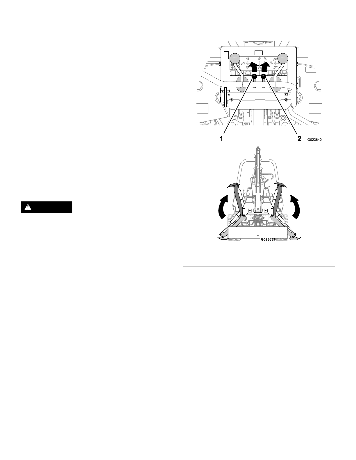
andrightlevers;refertoRaisingtheStabilizers(page30)
andLoweringtheStabilizers(page30).Movingthelevers
downwardlowersthestabilizerarms;movingthelevers
upwardraisesthestabilizerarms.
3.Pushthestabilizercontrolforwarduntilthestabilizers
hasremovedtheweightofthemachinefromthefront
wheelsslightly(Figure48).
PositioningtheStabilizerArms
CAUTION
Whenexcavatingwithabackhoeonaslope,one
stabilizermaybelowerthantheother,causing
anunstablesetupthatcouldresultinatip-over
accident.
Alwaysdumpthebucketandplacethespoilonthe
uphillsideoftheexcavation.
•Lowerthestabilizerarmstoremovetheweightofthe
backhoefromthefrontwheels,butkeepatleast1wheel
inlightcontactwiththeground.Thisallowsthewidest
stanceandalowercenterofgravityforoperatingthe
backhoe.
•Keepingthefrontwheelslowallowsyoutodigatagreater
depthandreducesthestressonthebackhoecomponents.
•Onsteepslopes,levelthesurfacewithaloaderandplace
thespoilpileonthedownhillsideoftheslope.Packthe
spoilsothatitsupportsthestabilizerarmgoingintoit.
Usecanalsousethistechniquewhenyouareexcavating
nearanobstruction,suchasawall,thatisontheuphill
sideoftheexcavation.
Figure48
1.Leftstabilizercontrol
4.Asnecessary,adjusteachstabilizerindividuallytolevel
themachine.
5.Releasethestabilizercontrols.
2.Rightstabilizercontrol
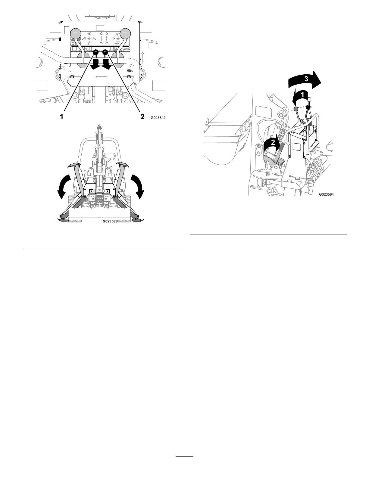
LoweringtheStabilizers
1.Settheenginespeedofthemachineto1/2to3/4
throttle.
2.Movetothebackhoeoperator’sseat.
3.Pullthestabilizercontrolbackwarduntilthestabilizer
hasmovedtothefullyuprightposition(Figure49).
RaisingtheStabilizers
Raisethestabilizersasfollows:
1.Settheenginespeedofthemachineto1/4throttle
orhigher.
2.Movetothebackhoeoperator’sseat.
30
Page 31
UsingtheBoomandSwing Locks
UnlockingtheBoomLock
1.Pushtheboomcontrolforward(Figure50).
Figure49
1.Leftstabilizercontrol
4.Releasethestabilizercontrols.
2.Rightstabilizercontrol
Figure50
1.Boomcontrolforward
2.Boom-latchhandle
rearward
2.Pulltheboom-latchhandlerearward(Figure50).
3.Pulltheboomcontrolrearward;thebackhoewillmove
outofthetransportlockedposition(Figure50).
Important:Alwaysoperatethebackhoewhile
seatedinthebackhoeoperator’sseat.
3.Boomcontrolrearward
LockingtheBoomLock
Note:Youmustlocktheboom,thedipper,andthebucket
beforeyoucansafelytransportthebackhoe.Referto
UnlockingtheSwingLock(page32).
1.Rotatethebucketup(crowdedin)completely;referto
ControllingtheDipperandtheBucket(page35).
2.Retractthedipper(crowdedin)completely;referto
ControllingtheDipperandtheBucket(page35).
3.Pulltheboom/swingcontrolrearward(Figure51).
Note:Thebackhoeboomwillmovetowardyou(past
theverticalposition).
31
Page 32
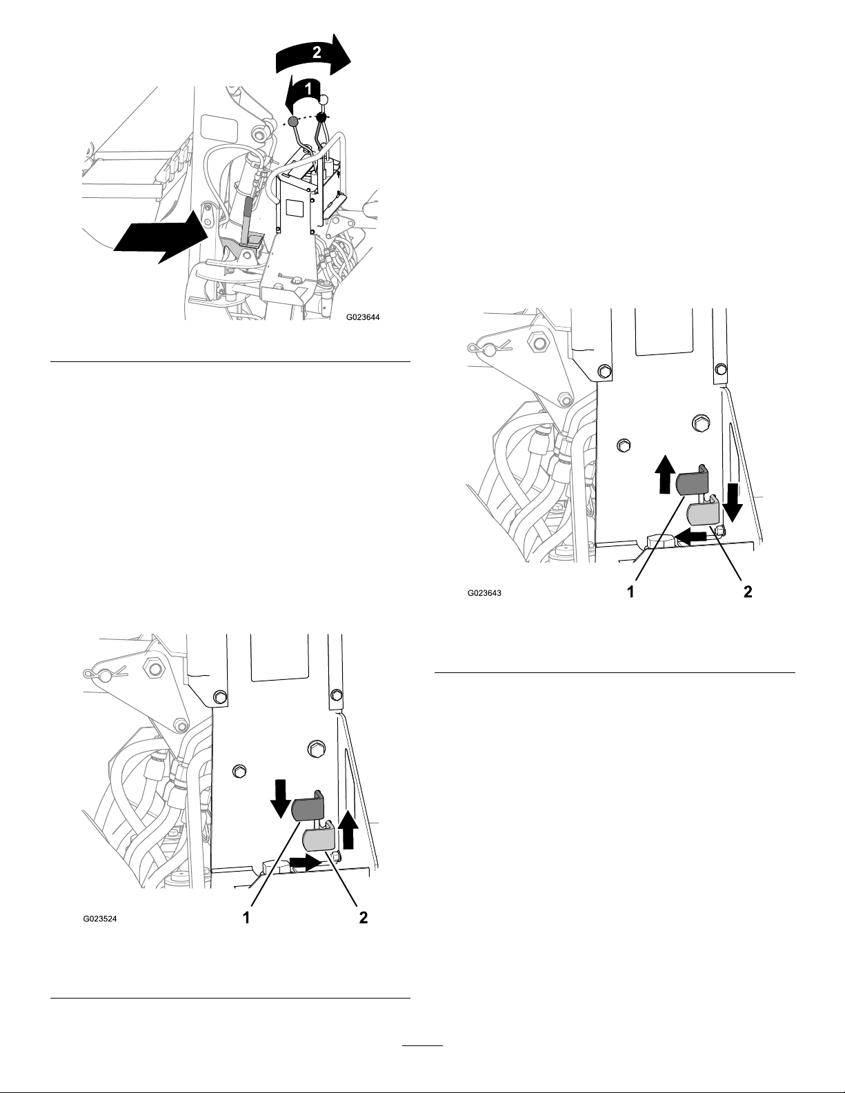
Figure51
4.Whentheboomreachestheverticalposition,rapidly
movetheboom/swingcontrolstraightforward(Figure
51).
2.Movetheswing-lockpedalforwardandreleasethe
pedal(Figure52).
LockingtheSwingLock
Note:Youmustcentertheboom,thedipper,andthebucket
lefttorightandlockthembeforeyoucansafelytransportthe
backhoe.RefertoLockingtheBoomLock(page31).
1.Raiseandcentertheboom,thedipper,andthebucket;
refertoControllingtheDipperandtheBucket(page
35).
2.Swingtheboom,thedipper,andthebuckettothe
centerpoint,betweenleftandright.
3.Pushtheswing-lockpedaldown(Figure53).
Note:Theboomwillmovetowardyouuntilitreaches
themechanicalstop.
Note:Theboomlockwillautomaticallyengagethe
boom.
5.Releasetheboom/dippercontrol(Figure51).
UnlockingtheSwingLock
1.Pushtheswing-lockpedaldowntoreleasethe
swing-lockcontrol(Figure52).
Figure53
1.Swing-lockpedal(locked
position)
2.Swing-lockpedal
(unlockedposition)
4.Movetheswing-lockpedalrearwardandreleasethe
pedal(Figure53).
1.Swing-lockpedal(locked
position)
Figure52
2.Swing-lockpedal
(unlockedposition)
32
Page 33
PreparingtoUsetheBackhoe
BeforeDiggingwiththeBackhoe
BeforeOperatingtheBackhoe
ServiceInterval:Beforeeachuseordaily
Important:Thebackhoeisnotacraneandshouldnot
beusedasone.Donotusethebackhoeasalifting
device.
WARNING
Bystandersunseenbytheoperatormaybetooclose
tothemachine,andthemachineordebristhrown
fromthemachinemaycauseseriousinjuryordeath.
Beforeoperatingthemachineinanareawith
reducedvisibility,installaguardrailandwarning
signstokeepothersawayfromthemachine.
WARNING
Operatingthemachinewhilenotseatedis
dangerousandcouldresultinseriousinjuryor
death.
WARNING
Co-workersandbystandersneartheworkingsite
couldcomeintocontactwiththemachineorthrown
debris,causingseriousinjuryordeath.
Beawareofwhereotherworkersareinthearea,
andkeepothersawayfromtheworkarea.
Stayintheoperator’sseatwheneveryouoperatethe
machine.
Thebackhoecandigmorematerialinlesstimewhenyouuse
asmooth,shortdigcycle;keepeachdigcyclesmooth.
Note:Beforeyouoperatethebackhoeforthersttime,read
andunderstandtheseinstructions.Thenmovethemachine
toanopenarea,runtheengineat1/3throttle,andactuate
eachbackhoecontrolleveruntileachmovementissmooth.
1.Checkthehydraulicsystem.
Note:Thebackhoeoperatesbymeansofthe
hydraulicsystemonthetractionunit.Forinformation
oncheckingthehydraulicuidlevelandthepressure
andreturnlters,refertoyourtractionunitOperator’s
Manual.
2.Checkallhardware,andtorqueanyloosefastenersas
needed.
3.Whiletheengineisoffandthebucketisontheground,
checkallhydraulichosesfordamageorwear.
Note:Checkforanyhydraulicuidleaksandensure
thatallhosettingsaretight.
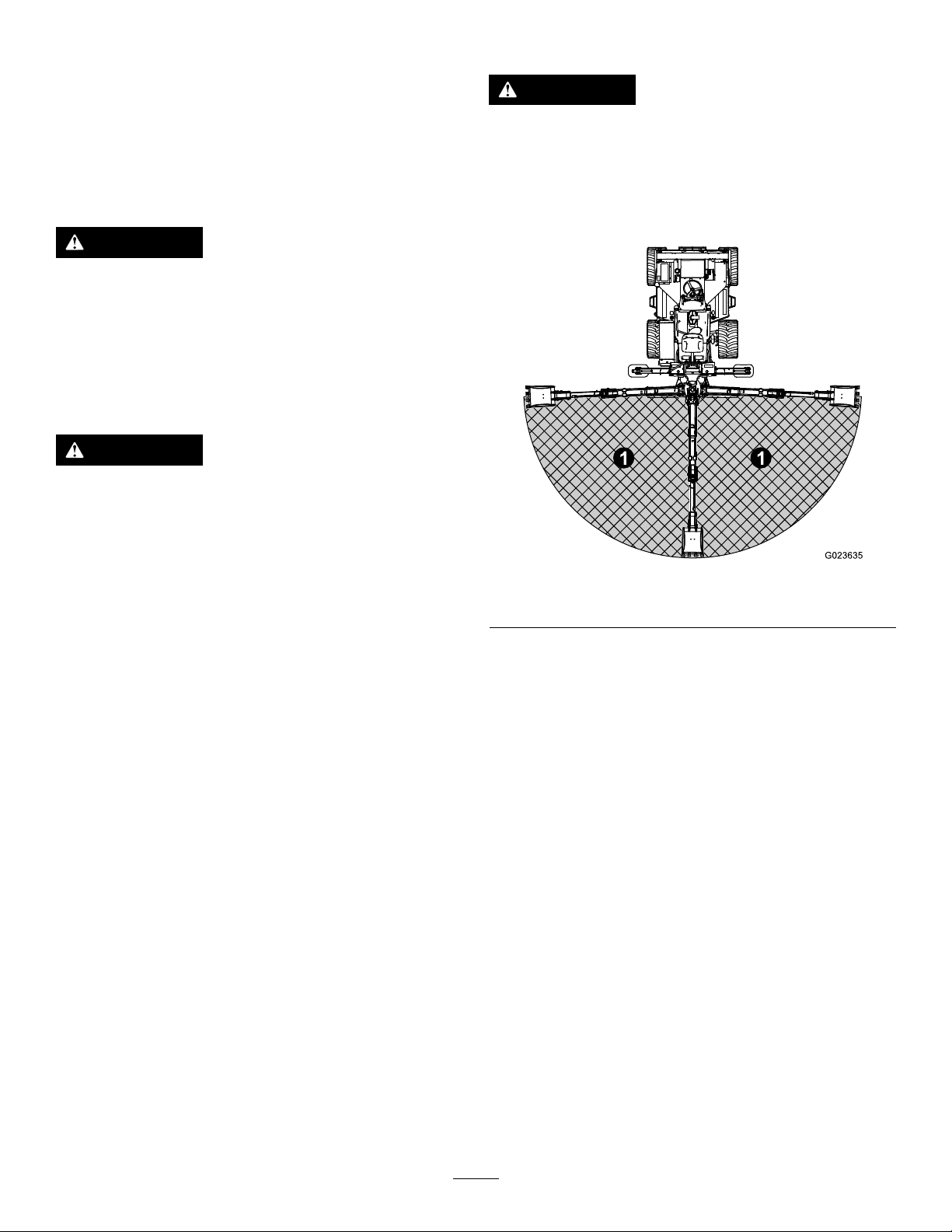
Figure54
1.Dangerarea
Important:Beforeyouoperatethebackhoe,ensurethat
eachcontrolisfunctioningproperly;makeallnecessary
repairsoradjustmentsbeforeyouoperatethebackhoe.
1.Identifythelocationofallundergroundcables,
pipelines,andoverheadelectriclinesinthearea.
2.Removealllargerocks,stumps,orotherobstructions
beforeyoubegindigging.
3.Alignthemachinewiththenewdiggingarea.
4.Beforeleavingtheoperator’sseatforthemachine,
performthefollowing:
A.Putthegrounddriveandattachmentcontrolsin
theNeutralposition.
Note:Theneutralindicatorlightshould
illuminate.
B.Settheparkingbrake.
Note:Theparkingbrakelightshouldilluminate.
C.Adjusttheenginespeedbetween1/2to3/4
throttle,andsetthethrottlelock.
5.Holdontothehandrailsandusethewalkway(Figure
55)togotothebackhoeoperator’sseat.
33
Page 34
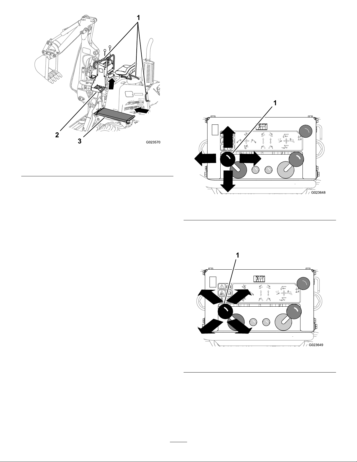
Figure55
1.Handrails3.Walkway
2.Foothold
6.Lowerthestabilizerstotheground,andlifttheweight
ofthemachineoffthefronttires;refertoLowering
theStabilizers(page30).
ControllingtheBackhoe
ControllingtheBoomandtheSwing
Youcancontroltheboomandtheswingofthebackhoeby
operatingtheleftlever(Figure56)asfollows:
•Pushthisleverforwardtolowertheboom;pullit
rearward(towardyou)toraisetheboom.
•Movethislevertothelefttoswingthebuckettotheleft;
moveittotherighttoswingthebuckettotheright.
Figure56
7.Unlocktheswinglockofthebackhoe;referto
UnlockingtheSwingLock(page32).
8.Takethebackhoeoutofthetransportlockedposition;
refertoMovingtheBackhoeintotheTransport
Position(page36).
1.Boomextensionandswingcontrollever
Note:Bymovingtheleverinan“X”patternratherthan
merelya“+”pattern,youcanraiseorlowerandswing
thebackhoeatthesametime(Figure57).
Figure57
1.Boomextensionandswingcontrollever
34
Page 35
ControllingtheDipperandtheBucket
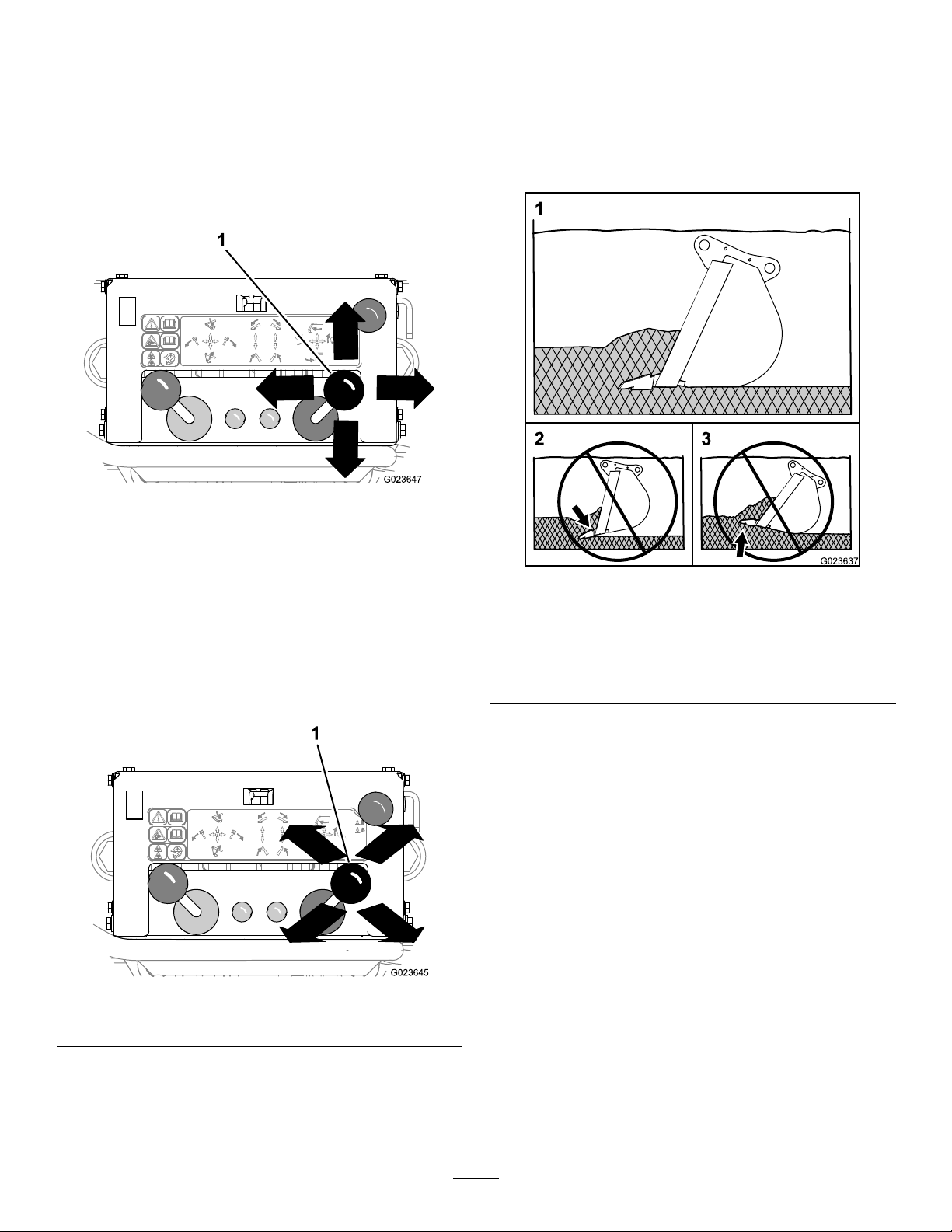
Youcancontrolthedipperandthebucketbyoperatingthe
rightlever(Figure58)asfollows:
•Pushthisleverforwardtoextend(“crowdout”)the
dipperandtheboom;pullitrearward(towardyou)tocurl
(“crowdin”)thedipperandtheboom.
•Movethislevertothelefttocurl(“crowdin”)thebucket
tollit;movethelevertotherighttodumpthebucket.
Figure58
DiggingwiththeBackhoe
FillingtheBucket
Fillthebucketbyoperatingthedipper,theboom,andthe
bucketasnecessarytokeepthebottomofthebucketparallel
withthecut(Figure60).
1.Dipper/bucketcontrol
Note:Bymovingtheleverinan“X”patternratherthan
merelya“+”pattern,youcancurlinandfullthebucketor
extend(“crowdout”)anddumpthebucketatthesametime
(Figure59).
Note:Withexperience,youwillbeabletousebothleversat
thesametimewithease,liftingorlowering;swingingleftor
right;andllingordumpingallinonesmoothmotion.
Figure60
1.Correct(thebucketis
parallelwiththecut)
2.Wrong(thebucketwilldig
inandcauseastall)
3.Wrong(thebucketis
pushedup,resultingina
slowcycletime)
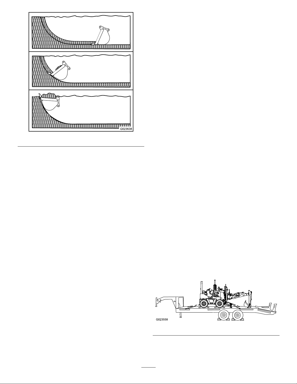
Allowthebucketteethandcuttingedgetocutthroughthe
groundlikeaknifeblade(Figure61).Thetypeofmaterial
thatyouarediggingdeterminesthedepthofthecut.
Note:Donotbackllatrenchbyswingingthebackhoe
bucketagainstthesoil;instead,usethebackllblade.
1.Dipper/bucketcontrol
Figure59
35
Page 36
3.Raisetheswing-lockpedaltolockit;refertoLocking
theSwingLock(page32).
4.Rotatethebucketcompletelyinandretractthedipper;
refertoControllingtheDipperandtheBucket(page
35).
5.Locktheboomtotheuprightposition;referto
LockingtheBoomLock(page31).
Note:Thebackhoeboomwillmovetowardyou(past
verticalposition)duringthisprocedure.
6.Raisethestabilizerscompletely;refertoRaisingthe
Stabilizers(page30).
MovingtheMachineRearwardwhile
DiggingwithaBackhoe
1.Raisethestabilizersandthebucketabovetheground;
refertoRaisingtheStabilizers(page30).
2.Gobacktothemachineoperator’sseat.
Figure61
DiggingaStraightWall
1.Stripthetopsoiloffthegroundwithintheboundaries
markedforastraightholeorgrave.
2.Removeasmuchmaterialwithintheboundariesas
possibleusingtheusualdiggingtechniques.
3.Makeaverticalfarwallbycrowdingoutthebucket
whileforcingitdownwiththeboom.
4.Curlthebuckettoensurethatthebottomofthebucket
remainsverticalwhenyoumakethedownwardcut.
5.Makeaverticalnearwallbyraisingtheboomwhile
crowdingitin.
Note:Curlthebucketinwardtokeepthecuttingedge
horizontalwiththenearwallasyouraisethebucket
andremovethesoil.
Note:Whenyouarenishingastraightwallinsandy
soil,useaplatformunderthereartiresandstabilizers
todistributetheweightofthebackhoeoveralarger
areatoreducethechanceofacave-in.
Note:Youmustbeseatedintheoperator’sseatbefore
movingthemachine;otherwise,theenginewillstop
in1second.
3.Releasetheparkingbrake.
4.EnsurethatthetransmissionisintheW orkposition.
5.Movethemachinerearwardtoanewposition.
6.EnsurethatthegrounddrivecontrolisintheNeutral
positionandthattheneutralindicatorlightison.
7.Settheparkingbrake.
8.Returntothebackhoeoperator’sseat.
9.Lowerthestabilizerstotheground,andremovethe
weightofthemachineoffthetires;refertoLowering
theStabilizers(page30).
TransportingtheMachine
LoadingandUnloadingtheMachine
Important:Ensurethatthetrailerandtherampcan
supporttheweightofboththetractionunitandthe
attachment(938.5kgor2069lb).
1.Blockthefrontandrearwheelsofthetransportvehicle.
MovingtheBackhoeandthe Machine
MovingtheBackhoeintotheTransport
Position
1.Decreasetheenginespeedto1/4throttle,andensure
thatthestabilizersareontheground.
2.Swingtheboomtothecenter.
Figure62
2.Movethebackhoeandthestabilizerstothetransport
position;refertoMovingtheBackhoeintothe
TransportPosition(page36).
36
Page 37

3.Slowlydrivethemachineontothetransportvehicle.
4.Settheparkingbrakeonthemachine.
5.Atthebackhoeconsole,releasetheboomlockand
lowertheboomandthedipperuntilthebucketis
restingonthedeckofthetransportvehicle(Figure62).
6.Stoptheengineandremovethekey.
SecuringtheMachinetotheTransport
Vehicle
1.Fastenthebackhoetothetrailerusingchainsand
binders(Figure62).
Note:Usethetiedownpointsonthemountingplates
forthebackhoe.
2.Fastenthebackofthemachinetothetrailerusing
chainsandbinders(Figure62)
Note:Usetherearaxletosecuretherearofthe
machine.
3.Secureblockingtothedeckofthetransportvehiclein
frontofthetiresandbehindthetiresofthemachine
(Figure62).
theboom,anddumpthebucketinthespoilareaonthe
highside(ifthereisone)ofthetrenchorexcavation.
•Carefullyplanwhereyouwilldepositthespoilthatyou
removefromtheexcavation.Thelocationofthespoil
pilewilldependonwhattypeofexcavationyouare
conducting.
•Tokeeptheheightofthespoilpilelow ,movethefull
buckettowardthespoilpile,lowerthebucketintothe
topofthepile,anddumpthecontentsandcrowdoutat
thesametime.Asthebucketdumps,thebottomofthe
bucketwillpushthetopofthepileoffandbehind,safely
awayfromtheexcavation.
•Whenyouaretransportingthemachinewithanattached
backhoeorwhenyouareusingthebackllblade,lock
theboomandswingofthebackhoetopreventitfrom
moving.
•Wheneveryouloadthemachinewiththebackhoeontoa
trailer,releasetheboomlock,lowerthebackhoebucket
ontotheoorbedofthetrailer,shuttheengineoff,and
removethekey.
OperatingTips
CAUTION
Diggingunderthestabilizerarms,diggingunder
thetractionunit,ordigginginsoftand/orwet
groundmaydisturbthestabilityoftheground
beneaththemachine,whichcouldresultina
tip-overaccident.
•Donotusethebackhoetodigunderthe
stabilizerarmsorunderthetractionunit.
•Donotdiginsoftorwetsoilconditions.
CAUTION
Placingalarge,heavyspoilpiletooclosetheedge
oftheexcavationcouldcauseacave-in,resulting
inpossiblepersonalinjuryanddamagetothe
equipment.
Donotplacethespoilpiletooclosetothe
excavation.
•Lowerthebuckettotheground,thencurlthebucket
untiltheteethareatontheground,retractthedipper,
dragthebucketthroughthetrenchuntilitthebucket
abouthalffull.Thencurlthebucketasyoucrowditin
untilthebucketiscompletelyfull;raisethebucket,swing
37
Page 38
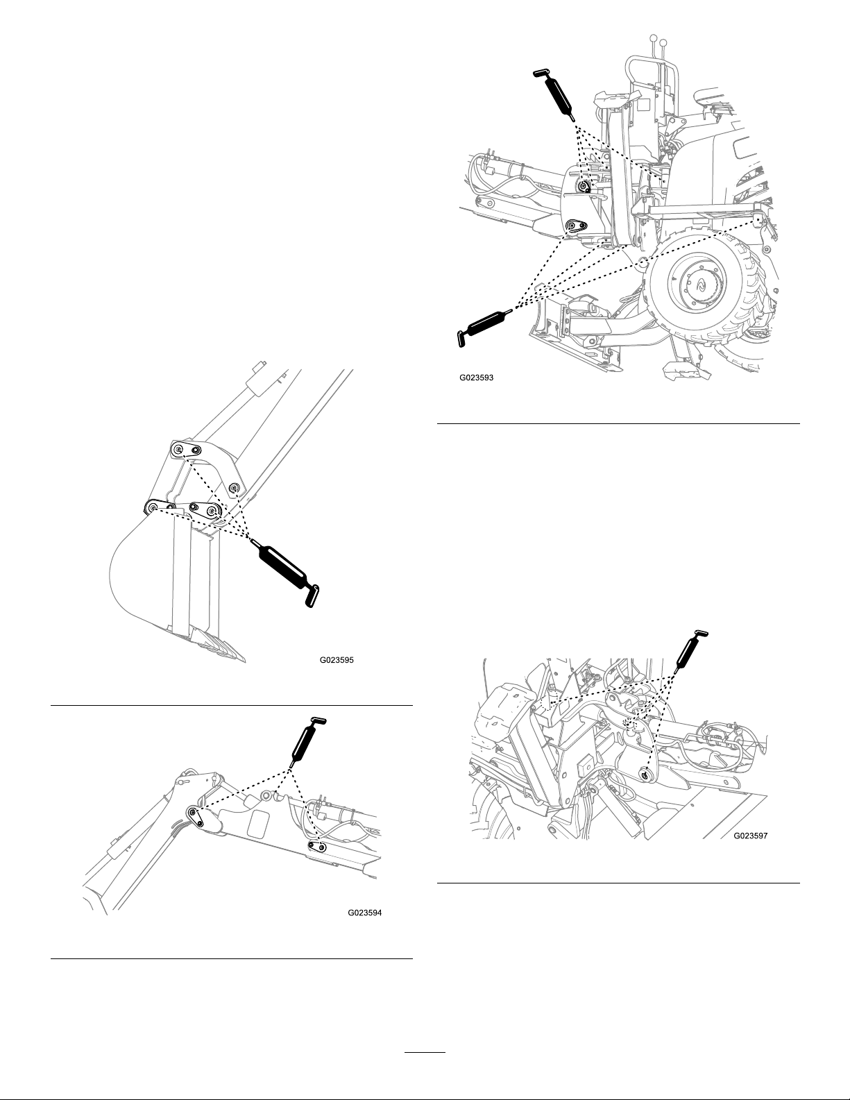
Maintenance
LubricatingtheBackhoe
ServiceInterval:Beforeeachuseordaily
GreaseType:Lithium-basedgrease.
GreasingtheFittingontheRightSide
oftheBackhoe
1.Cleanthegreasettingswitharag(Figure63,Figure
64,andFigure65).
2.Connectthegreaseguntothegreasettingsforthe
upperandlowerpivots;apply2or3pumpsofgrease
toeachtting(Figure63,Figure64,andFigure65).
3.Wipeupanyexcessgrease.
Figure65
Figure63
GreasingtheFittingontheLeftSideof
theBackhoe
1.Cleanthegreasettingswitharag(Figure66,Figure
67,andFigure68).
2.Connectthegreaseguntothegreasettingsforthe
upperandlowerpivots;apply2or3pumpsofgrease
toeachtting(Figure66,Figure67,andFigure68).
3.Wipeupanyexcessgrease.
Figure66
Figure64
38
Page 39
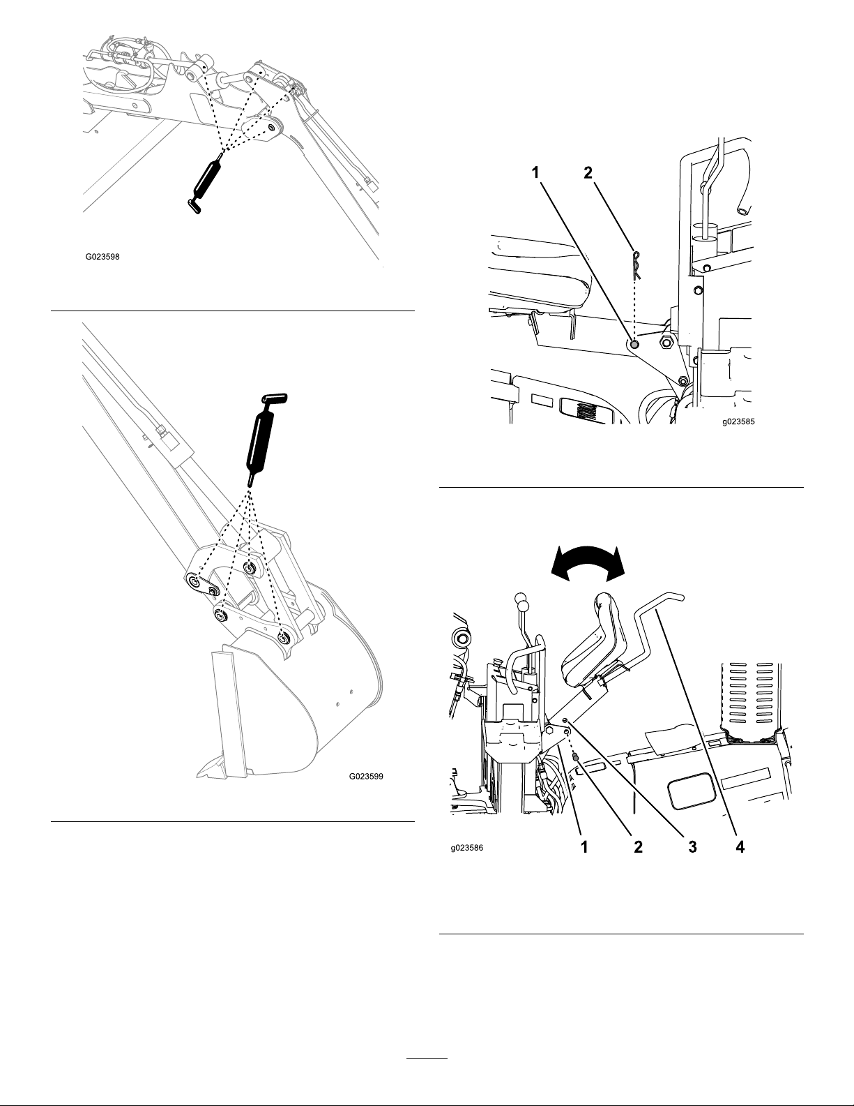
Figure67
RaisingandLoweringtheSeat
RaisingtheSeat
1.Removethehairpinfromtheseat-lockpin(Figure69).
Figure69
Figure68
1.Seat-lockpin
2.Hairpin
2.Removetheseat-lockpinfromthemountingplates
andtheseatpost(Figure70).
Figure70
1.Mountingplate
2.Seat-lockpin
3.Seatpost
4.Handrail
3.Liftuponthehandrailthatisattachedtotheback
oftheseat,andpivottheseatupandforwarduntil
thebottomoftheseatpostisabovetheholesinthe
mountingplates(Figure70).
39
Page 40

4.Fullyinserttheseat-lockpinthroughtheholesinthe
mountingplates(Figure70).
Storage
5.Installthehairpinintotheholeintheseat-lockpin
(Figure69).
LoweringtheSeat
1.Removethehairpinfromtheseat-lockpin(Figure69).
2.Removetheseat-lockpinfromthemountingplates
(Figure70).
3.Movethehandrail(attachedtothebackoftheseat)
downuntiltheholeintheseatpostisalignedwiththe
holesinthepivotbrackets(Figure70).
4.Installtheseat-lockpinandthehairpin(Figure69).
•Whenyouarenotusingthebackhoe,storeitindoorsina
cleananddryplace.
Note:Ifyouarenotabletostorethebackhoeindoors,
coverthebackhoetokeepmoisture,dirt,anddebris.
•Greaseallexposedcylinderrodstopreventthemfrom
rusting.
•Repairorreplaceanyworn,damage,ormissingpartson
thebackhoe.
•Installdustcapsontothehydraulicnipplestopreventthe
hydraulicsystemfromcontamination.
40
Page 41

Notes:
41
Page 42

Notes:
42
Page 43

Notes:
43
Page 44

TheToroUndergroundWarranty
ALimitedWarranty
Underground
Equipment
ConditionsandProductsCovered
TheToroCompanyanditsafliate,ToroWarrantyCompany,pursuant
toanagreementbetweenthem,jointlywarrantyourToroUnderground
Equipment(“Product”)tobefreefromdefectsinmaterialsorworkmanship.
Whereawarrantableconditionexists,wewillrepairtheProduct
atnocosttoyouincludingdiagnostics,labor,andparts.
ThefollowingwarrantyappliesfromthedatetheProductisdeliveredtothe
originalretailpurchaserorrentalowner.
ProductsWarrantyPeriod
EnginePoweredUnits&FluidMixers
AllSerializedAttachments
RockHammer6months
Engines
1yearor1000operatinghours,
whicheveroccursrst
1year
Throughenginemanufacturers:
2yearsor2000operatinghours,
whicheveroccursrst
InstructionsforObtainingWarrantyService
YouareresponsiblefornotifyingtheUndergroundDealerfromwhomyou
purchasedtheProductassoonasyoubelieveawarrantablecondition
exists.IfyouneedhelplocatingaUndergroundDealer ,orifyouhave
questionsregardingyourwarrantyrightsorresponsibilities,youmay
contactusat:
ToroCustomerCare
ToroWarrantyCompany
811 1LyndaleAvenueSouth
Bloomington,MN55420-1196
TollFreeat855-493-0088(U.S.Customers)
1-952-948-4318(InternationalCustomers)
OwnerResponsibilities
AstheProductowner,youareresponsibleforrequiredmaintenanceand
adjustmentsstatedinyourOperator'sManual.Failuretoperformrequired
maintenanceandadjustmentscanbegroundsfordisallowingawarranty
claim.
ItemsandConditionsNotCovered
Notallproductfailuresormalfunctionsthatoccurduringthewarranty
periodaredefectsinmaterialsorworkmanship.Thiswarrantydoesnot
coverthefollowing:
•Productfailureswhichresultfromtheuseofnon-T ororeplacement
parts,orfrominstallationanduseofadd-on,ormodiednon-Toro
brandedaccessoriesandproducts.Aseparatewarrantymaybe
providedbythemanufactureroftheseitems.
•Productfailureswhichresultfromfailuretoperformrecommended
maintenanceand/oradjustments.Failuretoproperlymaintainyour
ToroproductpertheRecommendedMaintenancelistedinthe
Operator’sManualcanresultinclaimsforwarrantybeingdenied.
•ProductfailureswhichresultfromoperatingtheProductinanabusive,
negligent,orrecklessmanner.
•Partssubjecttoconsumptionthroughuseunlessfoundtobedefective.
Examplesofpartswhichareconsumed,orusedup,duringnormal
Productoperationinclude,butarenotlimitedto:brakes,lters,lights,
bulbs,belts,tracksortires,diggingteeth,diggingbooms,digging,
drive,ortrackchains,trackpads,drivesprockets,idlers,rollers,
blades,cuttingedges,orothergroundengagingcomponents.
•Failurescausedbyoutsideinuence.Conditionsconsideredtobe
outsideinuenceinclude,butarenotlimitedto,weather,storage
practices,contamination,useofunapprovedfuels,coolants,lubricants,
additives,water,orchemicals,etc.
•Failureorperformanceissuesduetotheuseoffuels(e.g.gasoline,
diesel,orbiodiesel)thatdonotconformtotheirrespectiveindustry
standards.
•Normalnoise,vibration,wearandtear ,anddeterioration.
•Normal“wearandtear”includes,butisnotlimitedto,damagetoseats
duetowearorabrasion,wornpaintedsurfaces,scratcheddecals,etc.
•Haulingexpenses,traveltime,mileage,orovertimeassociatedwith
transportingproducttotheauthorizedT orodealer.
Parts
Partsscheduledforreplacementasrequiredmaintenanceinthe
Operator’sManual,arewarrantedfortheperiodoftimeuptothescheduled
replacementtimeforthatpart.Partsreplacedunderthiswarrantyare
coveredforthedurationoftheoriginalproductwarrantyandbecomethe
propertyofT oro.Torowillmakethenaldecisionwhethertorepairany
existingpartorassemblyorreplaceit.Toromayuseremanufacturedparts
forwarrantyrepairs.
MaintenanceisatOwner’sExpense
Enginetune-up,lubrication,cleaningandpolishing,replacementoflters,
coolant,andcompletingrecommendedmaintenancearesomeofthe
normalservicesT oroproductsrequirethatareattheowner’sexpense.
GeneralConditions
RepairbyanAuthorizedToroUndergroundDealerisyoursoleremedy
underthiswarranty.
NeitherTheToroCompanynorToroWarrantyCompanyisliablefor
indirect,incidentalorconsequentialdamagesinconnectionwiththe
useoftheToroProductscoveredbythiswarranty,includingany
costorexpenseofprovidingsubstituteequipmentorserviceduring
reasonableperiodsofmalfunctionornon-usependingcompletion
ofrepairsunderthiswarranty.ExceptfortheEmissionswarranty
referencedbelow,ifapplicable,thereisnootherexpresswarranty.All
impliedwarrantiesofmerchantabilityandtnessforusearelimitedto
thedurationofthisexpresswarranty.
Somestatesdonotallowexclusionsofincidentalorconsequential
damages,orlimitationsonhowlonganimpliedwarrantylasts,sotheabove
exclusionsandlimitationsmaynotapplytoyou.Thiswarrantygivesyou
speciclegalrights,andyoumayalsohaveotherrightswhichvaryfrom
statetostate.
Noteregardingenginewarranty:
TheEmissionsControlSystemonyourProductmaybecoveredby
aseparatewarrantymeetingrequirementsestablishedbytheU.S.
EnvironmentalProtectionAgency(EP A)and/ortheCaliforniaAirResources
Board(CARB).Thehourlimitationssetforthabovedonotapplytothe
EmissionsControlSystemWarranty.RefertotheEngineEmissionControl
WarrantyStatementsuppliedwithyourproductorcontainedintheengine
manufacturer’sdocumentationfordetails.
CountriesOtherthantheUnitedStatesorCanada
CustomerswhohavepurchasedT oroproductsexportedfromtheUnitedStatesorCanadashouldcontacttheirT oroDistributor(Dealer)toobtain
guaranteepoliciesforyourcountry ,province,orstate.IfforanyreasonyouaredissatisedwithyourUndergroundDealer’sserviceorhavedifculty
obtainingguaranteeinformation,contacttheToroimporter.
AustralianConsumerLaw:AustraliancustomerswillnddetailsrelatingtotheAustralianConsumerLaweitherinsidetheboxoratyourlocalT oro
Dealer.
374-0292RevB
 Loading...