

Page 1
FormNo.3374-144RevB
g019060
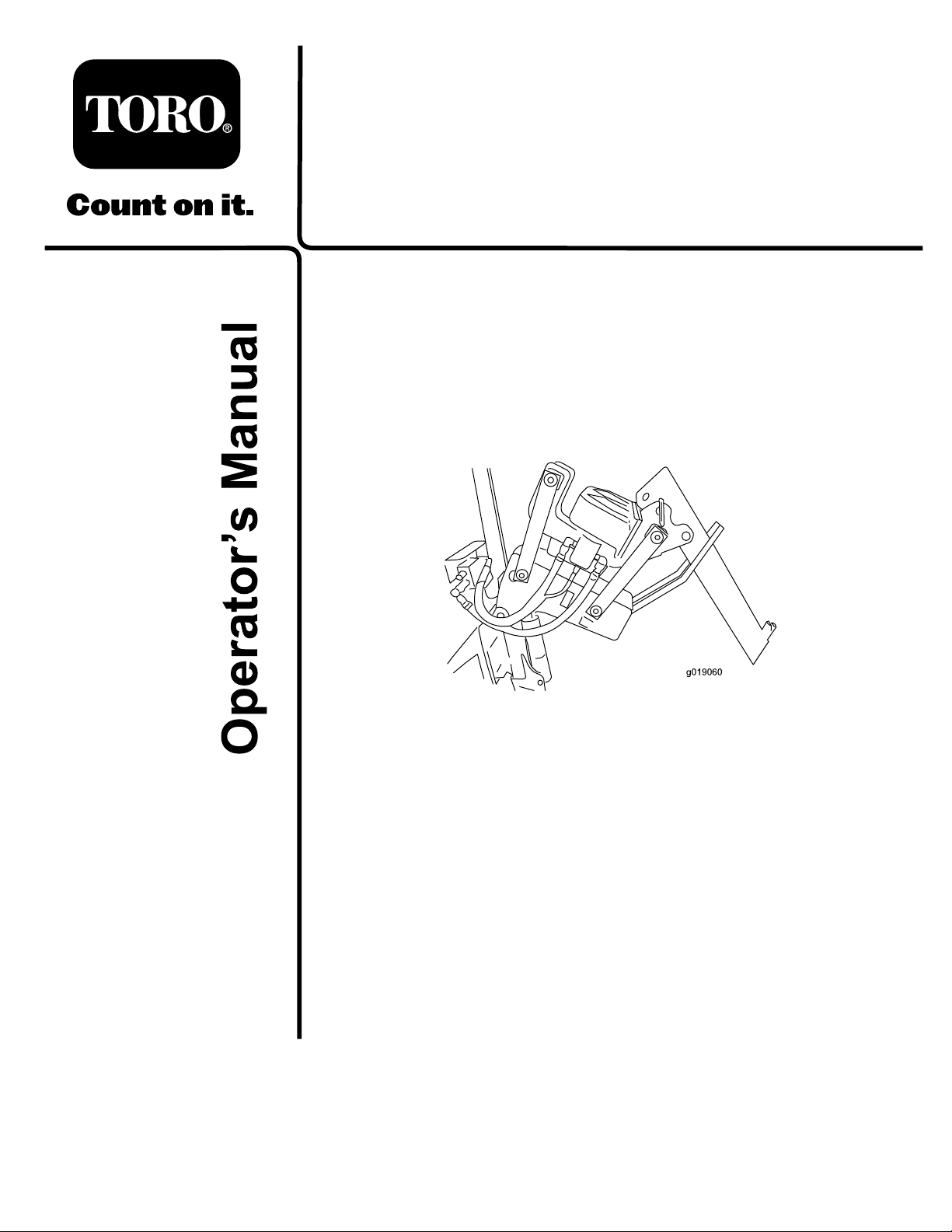
P40VibratoryPlow
ProSneak360VibratoryPlow
ModelNo.25402—SerialNo.313000001andUp
ModelNo.25402E—SerialNo.313000001andUp
Registeratwww.T oro.com.
OriginalInstructions(EN)
*3374-144*B
Page 2
WARNING
g019062
1
CALIFORNIA
Proposition65Warning
Thisproductcontainsachemicalorchemicals
knowntotheStateofCaliforniatocausecancer,
birthdefects,orreproductiveharm.
Theengineexhaustfromthisproduct
containschemicalsknowntotheStateof
Californiatocausecancer,birthdefects,
orotherreproductiveharm.
DANGER
Theremaybeburiedpower,gas,and/ortelephone
linesintheworkarea.Ifyoudigintothem,ashock
oranexplosionmayoccur.
Havethepropertyorworkareamarkedforburied
linesanddonotdiginmarkedareas.Contactyour
localmarkingserviceorutilitycompanytohavethe
propertymarked(intheUnitedStates,call811for
thenationwidemarkingservice).
Introduction
Thevibratoryplowisanattachmentdesignedforuseon
theT oroProSneakmachinetopullexiblepipeandcable
intoandthroughsoil.Itisdesignedtobeusedbytrained
operatorsprimarilyforroutingirrigationandutilitylines
undergroundwithouthavingtodigatrenchfortheentire
lengthofthepipeorcable.
Readthisinformationcarefullytolearnhowtooperateand
maintainyourproductproperlyandtoavoidinjuryand
productdamage.Youareresponsibleforoperatingthe
productproperlyandsafely.
YoumaycontactTorodirectlyatwww .Toro.comforproduct
andaccessoryinformation,helpndingadealer,ortoregister
yourproduct.
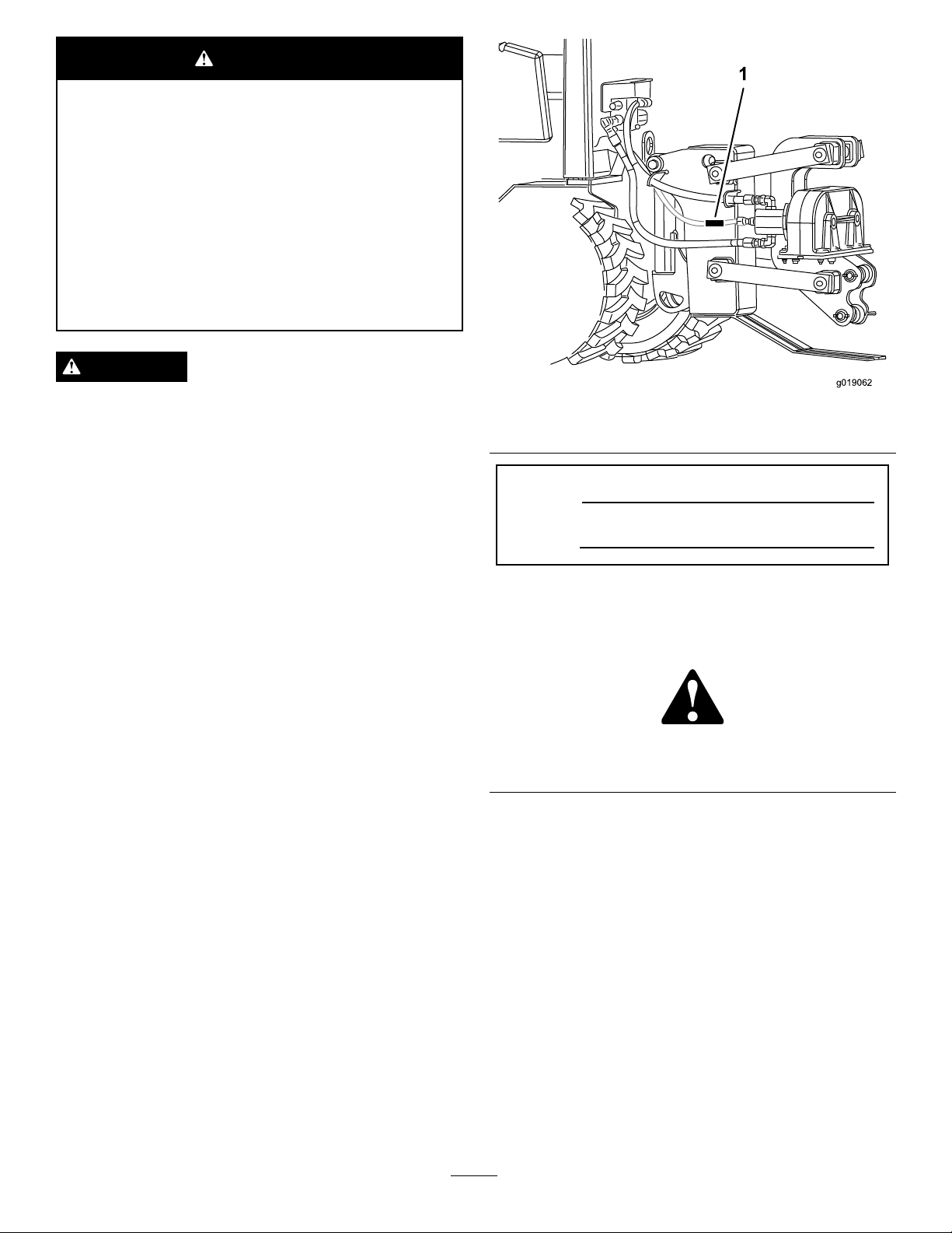
Figure1
1.Modelandserialnumberlocation
ModelNo.
SerialNo.
Thismanualidentiespotentialhazardsandhassafety
messagesidentiedbythesafetyalertsymbol(Figure2),
whichsignalsahazardthatmaycauseseriousinjuryordeath
ifyoudonotfollowtherecommendedprecautions.
Figure2
1.Safetyalertsymbol
Thismanualuses2wordstohighlightinformation.
Importantcallsattentiontospecialmechanicalinformation
andNoteemphasizesgeneralinformationworthyofspecial
attention.
Wheneveryouneedservice,genuineT oroparts,oradditional
information,contactanAuthorizedServiceDealerorToro
CustomerServiceandhavethemodelandserialnumbersof
yourproductready.
modelandserialnumbersontheproduct.Writethenumbers
inthespaceprovided.
©2014—TheToro®Company
8111LyndaleAvenueSouth
Bloomington,MN55420
Figure1identiesthelocationofthe
Contactusatwww.Toro.com.
2
PrintedintheUSA.
AllRightsReserved
Page 3

Contents
Safety
Introduction..................................................................2
Safety...........................................................................3
SafetyandInstructionalDecals.................................4
Setup............................................................................5
1AttachingthePlow................................................5
2RoutingtheHoses.................................................6
ProductOverview..........................................................7
Controls................................................................7
Specications.........................................................8
Operation.....................................................................8
Plowing..................................................................8
ChangingthePlowBlade..........................................9
RemovingandInstallingtheSkidShoes......................9
Maintenance.................................................................10
RecommendedMaintenanceSchedule(s)......................10
GreasingthePlow..................................................10
Storage........................................................................11
Troubleshooting...........................................................12
Improperuseormaintenancebytheoperatororowner
canresultininjury.Toreducethepotentialforinjury,
complywiththesesafetyinstructionsandthoseinthe
machine
safetyalertsymbol,whichmeans
Danger
withtheinstructionmayresultinpersonalinjuryor
death.
Operator's Man ual
—personalsafetyinstruction.Failuretocomply
.Alwayspayattentiontothe
Caution
,
W ar ning
DANGER
Contactwiththemovingplowcancutoramputate
hands,feet,orotherbodyparts.
•Keepyourhands,feet,andanyotherpartofyour
bodyorclothingawayfrommovingparts.
•Beforeadjusting,cleaning,repairing,and
inspectingtheplow,lowerittotheground,stop
theengine,removethekey,andwaitforall
movingpartstostop.
WARNING
Whentheengineisoff,attachmentsintheraised
positioncangraduallylower.Someonenearbymay
bepinnedorinjuredbyanattachmentasitlowers.
,or
Alwayslowertheattachmentswheneveryoushut
offthemachine.
WARNING
Theplowisveryloudduringoperation;overtime,
yourhearingmaybeimpairedifunprotected.
Wearhearingprotectionduringoperation.
WARNING
Lightningcancausesevereinjuryordeath.If
lightningisseenorthunderisheardinthearea,do
notoperatethemachine;seekshelter.
WARNING
Whentheplowisoutoftheground,bystanders
couldbeinjuredbytheswingingplow,and/orthe
machinecouldbeoverturnedbytheinertiaofthe
swingingplow,crushingyouorbystanders.
•Keeptheplowlowatalltimes.
•Usecautionwhenturning,anddonotturn
quickly.
•Keepallbystandersatleast2meters(6ft)away
whileoperating.
3
Page 4
CAUTION
WARNING
Hydrauliccouplers,hydrauliclines/valves,and
hydraulicuidmaybehotandcanburnyouifyou
touchthem.
•Weargloveswhenoperatingthehydraulic
couplers.
•Allowthemachinetocoolbeforetouching
hydrauliccomponents.
•Donottouchhydraulicuidspills.
SafetyandInstructionalDecals
Hydraulicuidescapingunderpressurecan
penetrateskinandcauseinjury.Fluidaccidentally
injectedintotheskinmustbesurgicallyremoved
withinafewhoursbyadoctorfamiliarwiththis
formofinjuryorgangrenemayresult.
•Ifequipped,makesureallhydraulicuid
hosesandlinesareingoodconditionandall
hydraulicconnectionsandttingsaretight
beforeapplyingpressuretohydraulicsystem.
•Keepbodyandhandsawayfrompinholeleaksor
nozzlesthatejecthighpressurehydraulicuid.
•Usecardboardorpaper,notyourhands,tond
hydraulicleaks.
•Safelyrelieveallpressureinthehydraulicsystem
byplacingthemotioncontrolleversinneutral
andshuttingofftheenginebeforeperforming
anyworkonthehydraulicsystem.
Safetydecalsandinstructionsareeasilyvisibletotheoperatorandarelocatednearanyareaofpotential
danger.Replaceanydecalthatisdamagedorlost.
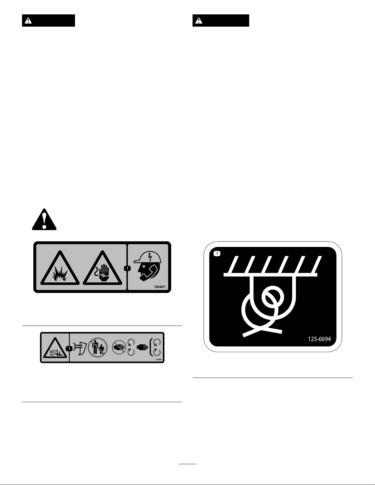
125-6671
1.Explosionhazard;electricshockhazard—calllocalutilities
beforedigging.
125–6684
1.Cutting/dismembermenthazard,plow—keepbystanders
awayfromtheplow;stayawayfrommovingparts;keepall
guardsandsafetiesinplace.
125–6694
1.Tiedownlocation
4
Page 5
Setup
1
2
3
g023248
LooseParts
Usethechartbelowtoverifythatallpartshavebeenshipped.
ProcedureDescription
1
2
1
AttachingthePlow
Partsneededforthisprocedure:
4Locknuts
4Bolts
1
Swinglock
10Washers
2Lynchpin
2Pivotpin
1
Liftpin
4
Snapring
1
Clevispin
Locknuts4
Bolts4
Swinglock
Washers10
Lynchpin2
Pivotpin2
Liftpin
Snapring
Clevispin
Nopartsrequired
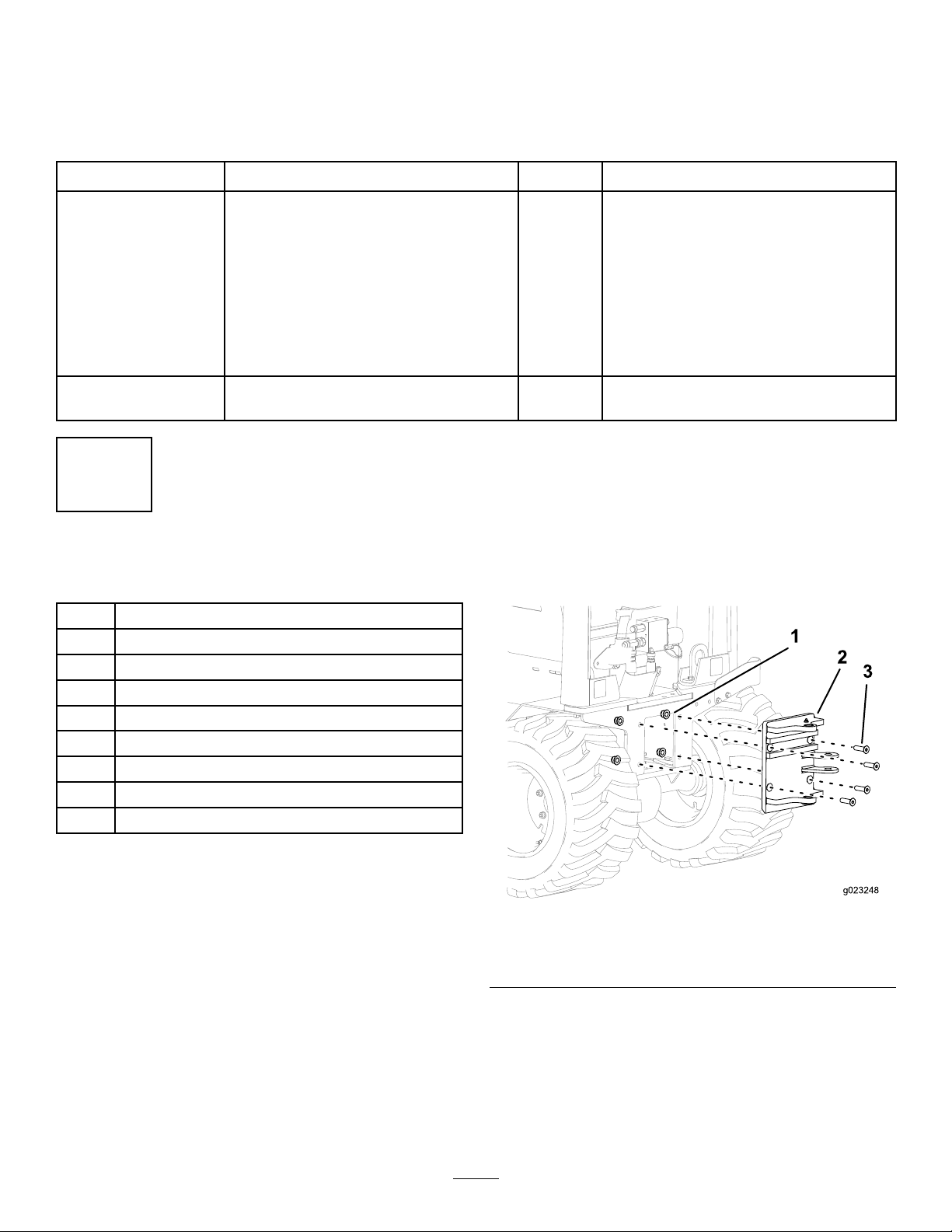
AttachingthePlowAttachmentPlate
Securetheattachmentplatetothemachineusing4bolts
and4locknutsandtorqueto321-392N-m(237-289ft-lb)
(Figure3).
Qty.
Use
1
Attachtheplow.
1
4
1
–
Routethehoses.
Figure3
1.Locknut(4)3.Bolt(4)
2.Attachmentplate
5
Page 6
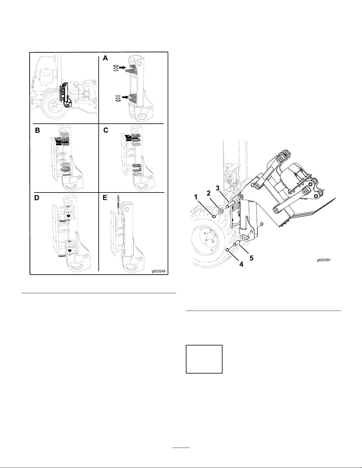
AttachingthePlowPivotAssembly
A
g023249
B
C
D
E
1
2
3
4
g022391
5
1.Place1washer(1inch)betweentherstandsecond
platesandbetweenthefourthandfthplatesonthe
plowassemblyasshowninFigure4;BoxA.
andsecondplatesontheplowassemblyandthe
bottomledgeoftheattachmentplateisbetween
thefourthandfthplatesontheplowassembly
(
Figure4;BoxC).
4.Placethe2plowpivotpinsthroughtheholeonthe
platesontheplowassembly,andsecurethemusingthe
2lockpins(Figure4;BoxD).
5.Placetheswinglockpinthroughtheholeonthe
attachmentplateandtheholeonthesecondplateof
theplowassembly(Figure4;BoxE).
AttachingthePlowAssembly
1.Attachtheplowassemblytothetopofthepivot
assembly,andsecurethemusingtheliftpin,2washers,
and2snaprings(Figure5).
Figure5
Figure4
2.Placeadditionalwashersbelowtherstwashertoshim
theextraspaceallowingagapfrom0to1washer
clearance.
Note:Thenumberofatwasherswillvarydepending
onthesizeofthetiresinstalled.
3.Placethepivotassemblyontotheattachmentplateas
follows:
1.Snapring4.Snapring
2.Washer
3.Liftpin
2.Securethebottomoftheplowassemblytothepivot
assemblyusingtheclevispinand2snaprings(Figure
5).
5.Clevispin
•Ifthe23inchtiresareinstalled,placethepivot
assemblyontotheattachmentplatesothatthe
topledgeontheattachmentplateisbetweenthe
secondandthirdplatesontheplowassembly
andthebottomledgeoftheattachmentplateis
betweenthefthandsixthplatesontheplow
assembly(
Figure4;BoxB).
•Ifthe26inchtiresareinstalled,placethepivot
assemblyontotheattachmentplatesothatthetop
ledgeontheattachmentplateisbetweentherst
2
RoutingtheHoses
NoPartsRequired
ConnectthehosefromportAtoportAandrepeatforport
BtoportB(
Figure6).
6
Page 7
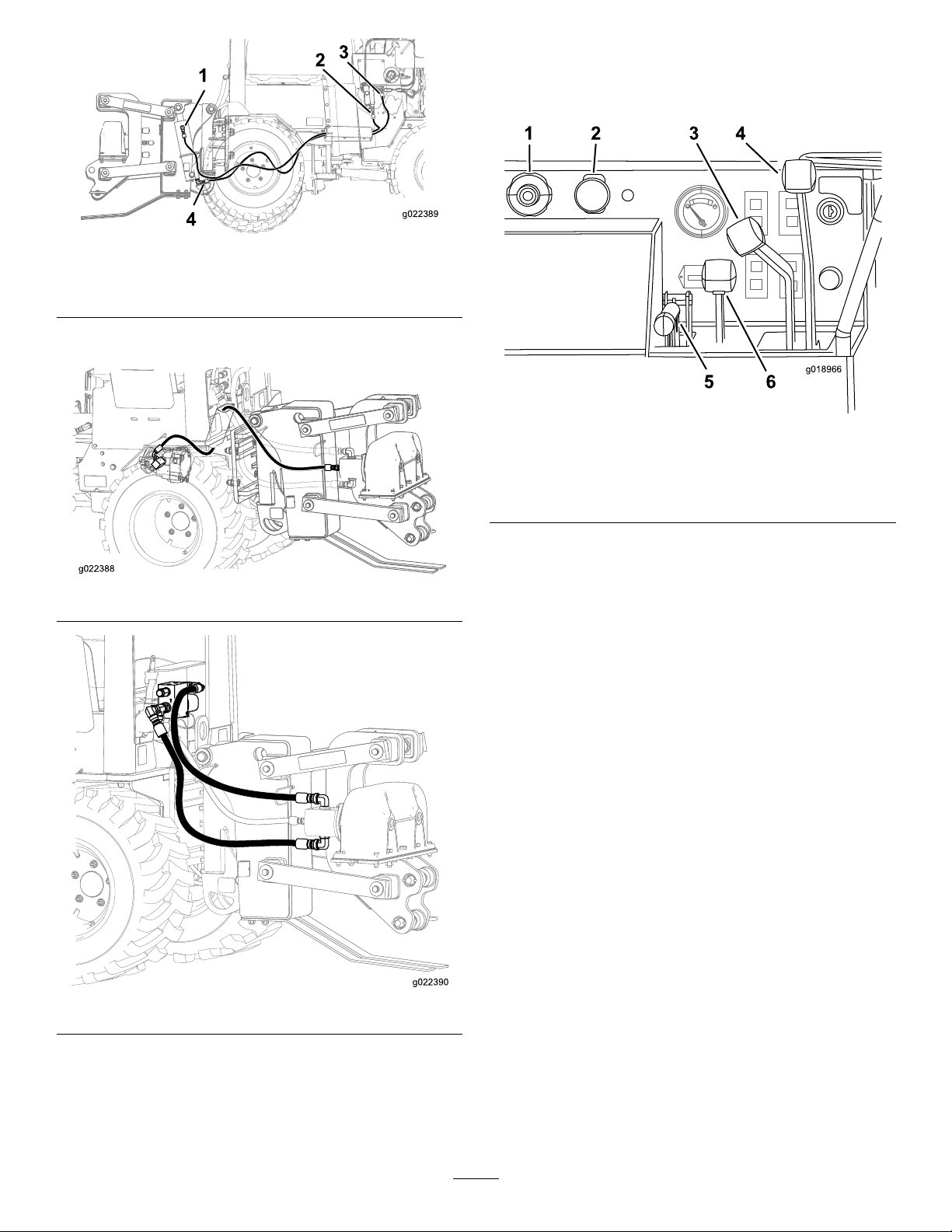
1
2
3
4
g022389
Figure6
g022388
g022390
1 2 3 4
5 6
g018966
1.PortA3.PortA
2.PortB4.PortB
ConnecttheexistinghosesasshowninFigure7andFigure8.
ProductOverview
Controls
Figure9
1.Throttle4.Directionalcontrollever
2.PTO
3.Creepcontrollever
5.Parkingbrake
6.Attachmentcontrollever
Figure7
Figure8
Throttle
Pushthebuttonatthecenteroftheknob,andpulltheknob
toincreasetheenginespeed(Figure9).
Pushthebuttonatthecenteroftheknob,andpushtheknob
intodecreaseenginespeed.
Note:Youcanrotatetheknobtomakesmalladjustments
totheenginespeed.Rotatetheknobcounterclockwiseto
increaseenginespeedandclockwisetodecreaseenginespeed.
PTOSwitch
ThePTOswitchcontrolsthevibratoryplow .
Pulltheswitchtostartthevibratoryplow.
Pushtheswitchtostopthevibratoryplow.
CreepControlLever
Thislevercontrolstheforwardandreversedirectionsandthe
machinespeedduringoperation.Thisleverhas5positions:
forward,reverse,neutral,right,andleft.Themachinewill
moveinthedirectionthatyoumovethelever.Thefarther
youpushorpullthelever,thefasterthemachinewillmove.
Theleverwilllockinpositionwhenyoureleaseit.
7
Page 8
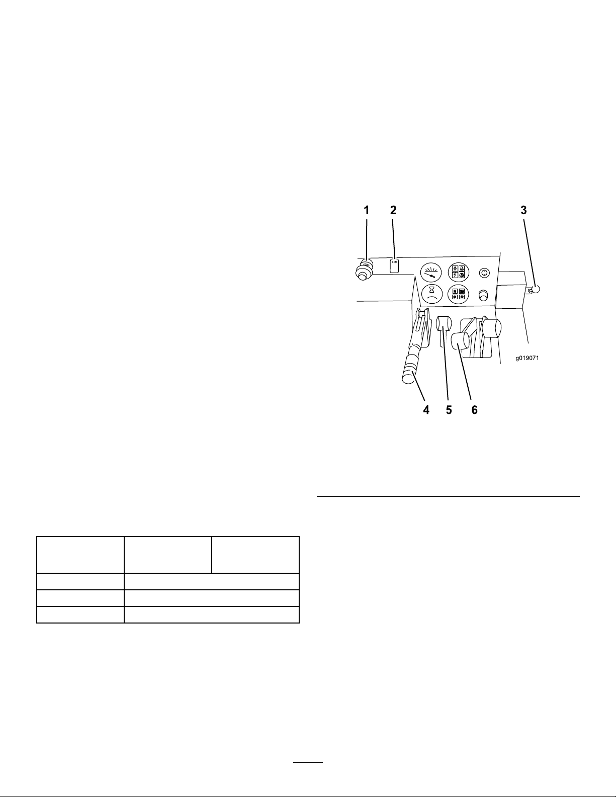
DirectionControlLever
1 2 3
g019071
N
SEAT
BELT
4 5 6
Thislevercontrolsthedirectionandspeedofthemachine.
Thisleverhas5positions:forward,reverse,neutral,right,
andleft.
Themachinewillmoveinthedirectionthatyoumovethe
lever.Thefartheryoupushorpullthelever,thefasterthe
machinewillmove.
•Movethelevertotheneutralpositiontostopthemachine.
•Fromtheneutralposition,pushtheleverslightlyfor
forwardgroundtravel.Pushtheleverfarthertoincrease
theforwardgroundspeed.Pulltheleverslightlyto
decreasetheforwardgroundspeed.
•Fromtheneutralposition,pulltheleverslightlyfor
reversegroundtravel.Pulltheleverfarthertoincreasethe
reversegroundspeed.Pushtheleverslightlytodecrease
thereversegroundspeed.
•Whilethemachineisinmotionpushtheleverslightlyleft
orrighttoturnthemachine.
Note:Thedirectionalcontrollevercannotbeusedtogo
forwardorreversewhenusingthecreepcontrollever.
Operation
RefertoyourmachineOperator’sManualformoreinformation
oninstallingandremovingtheattachmentsonyourmachine.
Important:Alwaysusethemachinetoliftandmove
theattachment.
Plowing
1.Starttheengine.
2.Whentheengineiswarm,pullthethrottleouttofull
throttle(Figure10).
ParkingBrakeLever
Tosettheparkingbrake,pulltheleverupandpushitforward.
Toreleasetheparkingbrake,pulltheleverbackanddown.
AttachmentControlLever
Theattachmentcontrolleverhas2positions:raiseandlower.
Pullthelevertolowertheattachment.Pushthelevertoraise
theattachment.
Specications
Note:Thespecicationsanddesignaresubjecttochange
withoutnotice.
Width
Length
Height
Weight
92cm(36inches)
wheelsmounted
narrow
295cm(1 16inches)
211cm(83inches)
1331kg(2934lb)
117cm(46inches)
wheelsmounted
wide
Figure10
1.Throttle5.Parkingbrake
2.PTO
3.Creep-controllever
4.Directional-controllever8.Attachment-selectorlever
6.Attachment-controllever
7.Trencher-controllever
3.Ifthemachineisequippedwithatrencher,movethe
attachmentselectorlevertothecableplowposition
(Figure10).
4.Usetheattachmentcontrollevertolowertheplowto
theground.
Note:Theenginewillturnoffin1secondifthe
operatorsseatisemptyandthedirection-control,
trencher-digging-control,orcreep-controlleversare
movedfromtheNeutralposition.
5.Releasetheparkingbrake.
Note:Donotstarttheplowvibrationuntiltheblade
tiphasenteredtheground.
6.PullthePTOswitchtostartthecableplowvibration.
7.Slowlylowertheplowbladeintothegroundasthe
machinemovesforward.
8
Page 9
8.Usethecreepcontrollevertocontrolthedirectionand
g022277
1
2
1
2
3
4
g021986
5
speedofthemachineduringplowing.Themachinewill
moveinthesamedirectionthatyoumovethelever.
Note:Themoreyoupushtheleverfromtheneutral
position,thefasterthemachinewilltravel.Thelever
willstayinthispositionwhenyoureleasethelever.
MovethelevertotheNeutralpositiontostopthe
machinetravel.
9.Usethedirectionorcreepcontrolleverstosteerthe
machinetotheleftorright.
Important:Donotreversethemachinewiththe
plowbladeintheground.
Important:Slowlylifttheplowbladeoutofthe
groundasthemachinemovesforward.
Note:Decreasethemachinespeedifthetiresslip
orthebladeraisesoutofthegroundduringplow
operation.
10.ReducethespeedofthemachineandpressthePTO
switchtostoptheplowvibrationbeforeraisingthe
bladeoutoftheground.
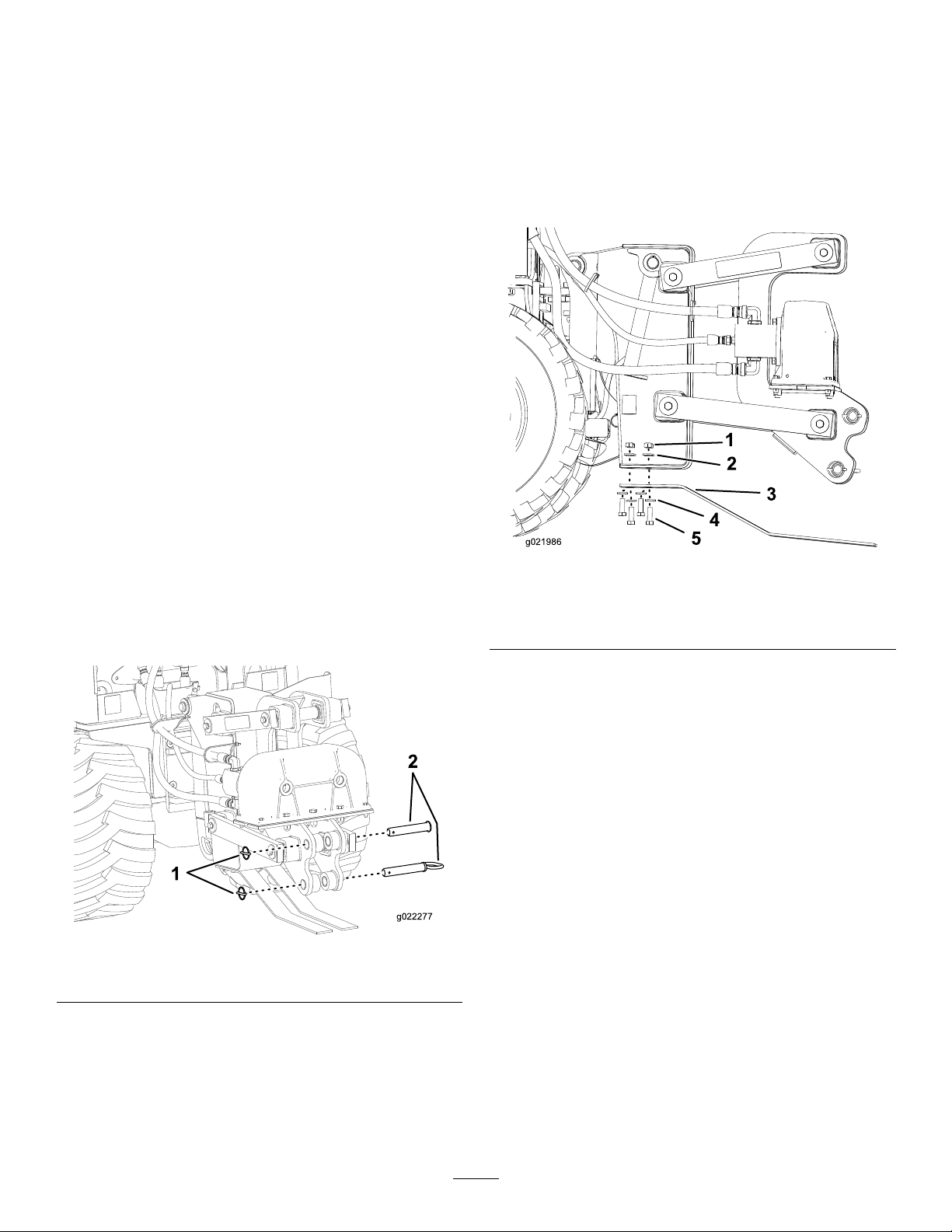
RemovingandInstallingthe SkidShoes
1.Raisetheplowabout91.4cm(36inches)offthe
ground.
2.Stoptheengineandremovethekey.
3.Removethe4bolts,4nuts,and8washersfromthe
skidshoes(Figure12).
ChangingthePlowBlade
Theplowbladesareheavy;use2peopletocompletethis
procedure.
1.Parkthemachineonalevelsurface,lowerany
attachments,andstoptheengine.
2.Flipthe2circularsnapringsoverandremovethe
snap-ringpin(Figure11).
Figure11
Figure12
1.Nut4.Washer
2.Washer5.Bolt
3.Skidshoes
4.Installthenewskidshoesandsecurethemwiththe
previouslyremovedhardware(Figure12).
1.Snap-ringpin
3.Pullthe2pinsoutoftheblade.
Note:Theplowbladesareheavy.Makesurethat1
personisholdingthebladewhiletheotherpersonis
removingthepins.
4.Placethenewbladeintotheplowbladeassemblyand
secureitwith2pinsand2snap-ringpins.
2.Pin
9
Page 10
Maintenance
g019061
g023247
RecommendedMaintenanceSchedule(s)
MaintenanceService
Interval
Beforeeachuseordaily
Beforestorage
MaintenanceProcedure
•Greasetheplow.
•Greasetheplow.
CAUTION
Ifyouleavethekeyintheignitionswitch,someonecouldstarttheengine.Accidentalstartingofthe
enginecouldseriouslyinjureyouorotherbystanders.
Removethekeyfromtheignitionswitchbeforeyoudoanymaintenance.
GreasingthePlow
ServiceInterval:Beforeeachuseordaily
Beforestorage
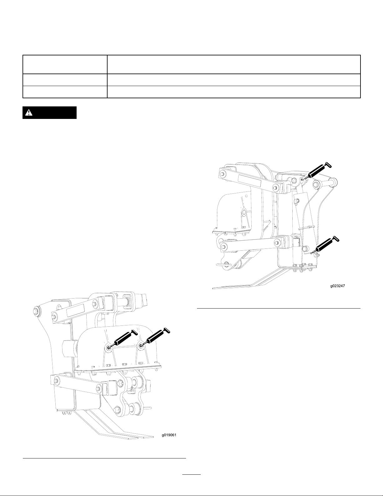
Greasethe4ttingsevery8operatinghours;refertoFigure
13andFigure14.
GreaseT ype:General-purposegrease
1.Stoptheengineandremovethekey.
2.Cleanthegreasettingswitharag.
3.Connectagreaseguntoeachtting.
4.Pumpgreaseintothettings.
5.Wipeupanyexcessgrease.
Figure14
Figure13
10
Page 11

Storage
1.Stoptheengineandremovethekey.
2.Removedirtandgrimefromtheexternalpartsofthe
attachmentwithamilddetergentandwater.
Important:Donotpressurewashtheattachment.
High-pressurewashingcandamagetheelectrical
systemandhydraulicvalvesordepletegrease.
3.Greasetheattachment;refertoGreasingthePlow
(page10).
4.Checkandtightenallbolts,nuts,andscrews.Repairor
replaceanypartthatisdamaged.
5.Checkthehydraulichosesforleaks,loosettings,
kinkedlines,loosemountingsupports,wear,weather
andchemicaldeterioration.Makenecessaryrepairs.
WARNING
Hydraulicuidescapingunderpressurecan
penetrateskinandcauseinjury.
•Ifhydraulicuidisinjectedintotheskinit
mustbesurgicallyremovedwithinafew
hoursbyadoctorfamiliarwiththistype
ofinjury.Gangrenemayresultifthisis
notdone.
•Keepyourbodyandhandsawayfrom
pinholeleaksornozzlesthateject
high-pressurehydraulicuid.
•Usecardboardorpapertondhydraulic
leaks.
•Safelyrelieveallpressureinthehydraulic
systembeforeperforminganyworkonthe
hydraulicsystem.
•Makesurethatallofthehydraulicuid
hosesandlinesareingoodconditionand
allhydraulicconnectionsandttingsare
tightbeforeapplyingpressuretohydraulic
system.
6.Paintallscratchedorbaremetalsurfaces.Paintis
availablefromyourAuthorizedServiceDealer.
7.Replaceallwornormissingdecals.Decalsareavailable
fromyourAuthorizedServiceDealer.
8.Covertheattachmenttoprotectitandkeepitclean.
11
Page 12

Troubleshooting
Theplowdoesnotoperate.
Problem
1.Thereisanobstructioninahydraulic
hose.
2.Ahydraulichoseiskinked.2.Replacethekinkedhose
3.Theauxiliaryvalveonthemachineis
notopening.
PossibleCauseCorrectiveAction
1.Findandremovetheobstruction.
3.Repairthevalve.
12
Page 13

Notes:
13
Page 14

Notes:
14
Page 15

Notes:
15
Page 16

ToroCompactUtilityEquipmentWarranty
AOne-Y earLimitedWarranty
CompactUtilityEquipment
(CUE)Products
ConditionsandProductsCovered
TheT oroCompanyanditsafliate,T oroWarrantyCompany,pursuantto
anagreementbetweenthem,jointlywarrantyourT oroCompactUtility
Equipment(“Product”)tobefreefromdefectsinmaterialsorworkmanship.
Thefollowingtimeperiodsapplyfromthedateofpurchase:
ProductsWarrantyPeriod
ProSneak
CompactUtilityLoaders,
Trenchers,StumpGrinders,
andAttachments
KohlerEngines3years
AllotherEngines2years
Whereawarrantableconditionexists,wewillrepairtheProductatnocost
toyouincludingdiagnosis,labor,andparts.
*
SomeenginesusedonToroProductsarewarrantedbytheenginemanufacturer.
1yearor1000operatinghours,
whicheveroccursrst
*
*
InstructionsforObtainingWarrantyService
IfyouthinkthatyourT oroProductcontainsadefectinmaterialsor
workmanship,followthisprocedure:
1.ContactanyAuthorizedToroCompactUtilityEquipment(CUE)
ServiceDealertoarrangeserviceattheirdealership.T olocatea
dealerconvenienttoyou,accessourwebsiteatwww.T oro.com.
YoumayalsocallourT oroCustomerCareDepartmenttollfreeat
thenumberbelow.
2.Bringtheproductandyourproofofpurchase(salesreceipt)tothe
ServiceDealer.
3.IfforanyreasonyouaredissatisedwiththeServiceDealer’s
analysisorwiththeassistanceprovided,contactusat:
SWSCustomerCareDepartment
ToroWarrantyCompany
811 1LyndaleAvenueSouth
Bloomington,MN55420-1196
TollFree:888-384-9940
OwnerResponsibilities
YoumustmaintainyourToroProductbyfollowingthemaintenance
proceduresdescribedintheOperator’sManual.Suchroutine
maintenance,whetherperformedbyadealerorbyyou,isatyourexpense.
Partsscheduledforreplacementasrequiredmaintenance(“Maintenance
Parts”),arewarrantedfortheperiodoftimeuptothescheduled
replacementtimeforthatpart.Failuretoperformrequiredmaintenance
andadjustmentscanbegroundsfordisallowingawarrantyclaim.
ItemsandConditionsNotCovered
Notallproductfailuresormalfunctionsthatoccurduringthewarranty
periodaredefectsinmaterialsorworkmanship.Thisexpresswarranty
doesnotcoverthefollowing:
•Productfailureswhichresultfromtheuseofnon-Tororeplacement
parts,orfrominstallationanduseofadd-on,modied,orunapproved
accessories
•Productfailureswhichresultfromfailuretoperformrequired
maintenanceand/oradjustments
•ProductfailureswhichresultfromoperatingtheProductinan
abusive,negligentorrecklessmanner
•Partssubjecttoconsumptionthroughuseunlessfoundtobe
defective.Examplesofpartswhichareconsumed,orusedup,during
normalproductoperationinclude,butarenotlimitedto,belts,wipers,
sparkplugs,tires,lters,gaskets,wearplates,seals,O-rings,drive
chains,clutches.
•Failurescausedbyoutsideinuence.Itemsconsideredtobeoutside
inuenceinclude,butarenotlimitedto,weather,storagepractices,
contamination,useofunapprovedcoolants,lubricants,additives,or
chemicals,etc.
•Normal“wearandtear”items.Normal“wearandtear”includes,butis
notlimitedto,wornpaintedsurfaces,scratcheddecals,etc.
•Repairsnecessaryduetofailuretofollowrecommendedfuel
procedure(consultOperator'sManualformoredetails)
–Removingcontaminantsfromthefuelsystemisnotcovered
–Useofoldfuel(morethanonemonthold)orfuelwhichcontains
morethan10%ethanolormorethat15%MTBE
–Failuretodrainthefuelsystempriortoanyperiodofnon-use
overonemonth
•Anycomponentcoveredbyaseparatemanufacturer’swarranty
•Pickupanddeliverycharges
GeneralConditions
RepairbyanAuthorizedT oroCompactUtilityEquipment(CUE)Service
Dealerisyoursoleremedyunderthiswarranty .
NeitherTheToroCompanynorToroWarrantyCompanyisliablefor
indirect,incidentalorconsequentialdamagesinconnectionwith
theuseoftheToroProductscoveredbythiswarranty ,including
anycostorexpenseofprovidingsubstituteequipmentorservice
duringreasonableperiodsofmalfunctionornon-usepending
completionofrepairsunderthiswarranty.Allimpliedwarranties
ofmerchantabilityandtnessforusearelimitedtotheduration
ofthisexpresswarranty.Somestatesdonotallowexclusionsof
incidentalorconsequentialdamages,orlimitationsonhowlong
animpliedwarrantylasts,sotheaboveexclusionsandlimitations
maynotapplytoyou.
Thiswarrantygivesyouspeciclegalrights,andyoumayalsohaveother
rightswhichvaryfromstatetostate.
ExceptfortheenginewarrantycoverageandtheEmissionswarranty
referencedbelow,ifapplicable,thereisnootherexpresswarranty .The
EmissionsControlSystemonyourProductmaybecoveredbyaseparate
warrantymeetingrequirementsestablishedbytheU.S.Environmental
ProtectionAgency(EPA)ortheCaliforniaAirResourcesBoard(CARB).
ThehourlimitationssetforthabovedonotapplytotheEmissions
ControlSystemWarranty.RefertotheCaliforniaEmissionControl
WarrantyStatementsuppliedwithyourProductorcontainedintheengine
manufacturer’sdocumentationfordetails.
CountriesOtherthantheUnitedStatesorCanada
CustomerswhohavepurchasedT oroproductsoutsidetheUnitedStatesorCanadashouldcontacttheirT oroDistributor(Dealer)toobtainguarantee
policiesforyourcountry,province,orstate.IfforanyreasonyouaredissatisedwithyourDistributor'sserviceorhavedifcultyobtainingguarantee
information,contacttheT oroimporter.Ifallotherremediesfail,youmaycontactusatT oroWarrantyCompany.
AustralianConsumerLaw:AustraliancustomerswillnddetailsrelatingtotheAustralianConsumerLaweitherinsidetheboxoratyourlocalT oro
Dealer.
374-0261RevE
 Loading...