

Page 1
FormNo.3402-234RevA
2024DirectionalDrill
ModelNo.23800—SerialNo.313000001andUp
ModelNo.23800A—SerialNo.314000001andUp
ModelNo.23800C—SerialNo.314000001andUp
ModelNo.23800W—SerialNo.314000001andUp
Registeratwww.T oro.com.
OriginalInstructions(EN)
*3402-234*A
Page 2
ThisproductcomplieswithallrelevantEuropeandirectives;
fordetails,pleaseseetheseparateproductspecicDeclaration
ofConformity(DOC)sheet.
YoumaycontactTorodirectlyatwww .Toro.comforproduct
andaccessoryinformation,helpndingadealer,ortoregister
yourproduct.
WARNING
CALIFORNIA
Proposition65Warning
Thisproductcontainsachemicalorchemicals
knowntotheStateofCaliforniatocausecancer,
birthdefects,orreproductiveharm.
Dieselengineexhaustandsomeofits
constituentsareknowntotheStateof
Californiatocausecancer,birthdefects,
andotherreproductiveharm.
Becauseinsomeareastherearelocal,state,orfederal
regulationsrequiringthatasparkarresterbeusedonthe
engineofthismachine,asparkarresterisavailableas
anoption.Ifyourequireasparkarrester,contactyour
AuthorizedToroServiceDealer.
GenuineT orosparkarrestersareapprovedbytheUSDA
ForestryService.
Important:ItisaviolationofCaliforniaPublic
ResourceCodeSection4442touseoroperatetheengine
onanyforest-covered,brush-covered,orgrass-covered
landwithoutasparkarrestermufermaintainedin
workingorder,ortheengineconstricted,equipped,and
maintainedforthepreventionofre.Otherstatesor
federalareasmayhavesimilarlaws.
Theenclosed
Engine Owner's Man ual
informationregardingtheUSEnvironmentalProtection
Agency(EPA)andtheCaliforniaEmissionControl
Regulationofemissionsystems,maintenance,and
warranty.Replacementsmaybeorderedthroughthe
enginemanufacturer.
issuppliedfor
Wheneveryouneedservice,genuineT oroparts,oradditional
information,contactanAuthorizedServiceDealerorToro
CustomerServiceandhavethemodelandserialnumbersof
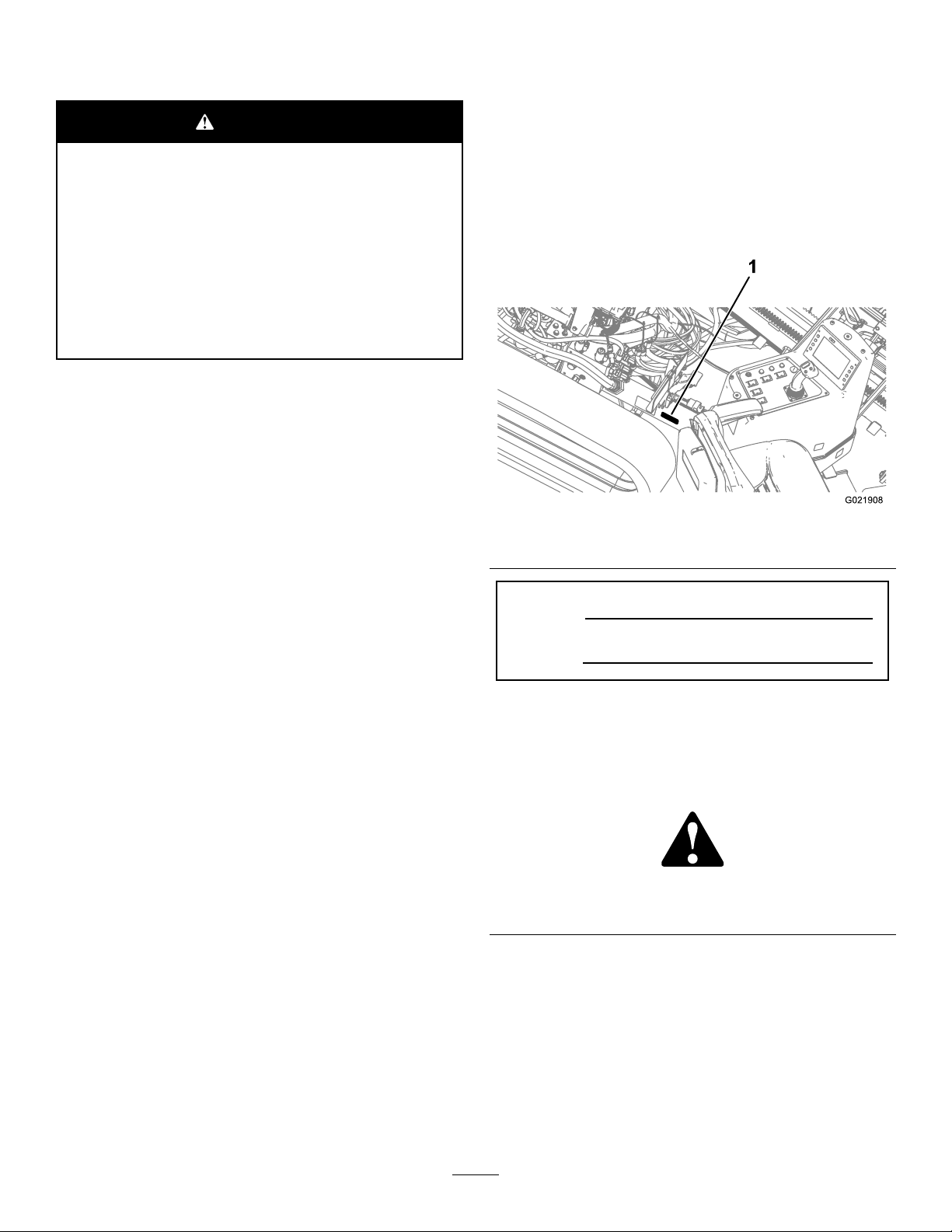
yourproductready.Figure1identiesthelocationofthe
modelandserialnumbersontheproduct.Writethenumbers
inthespaceprovided.
Figure1
1.Modelandserialnumberlocation
ModelNo.
SerialNo.
Thismanualidentiespotentialhazardsandhassafety
messagesidentiedbythesafetyalertsymbol(Figure2),
whichsignalsahazardthatmaycauseseriousinjuryordeath
ifyoudonotfollowtherecommendedprecautions.
Forradiofrequencycomplianceinformation,referto
your
Compliance Statement Addendum
thatpertains
toyourcountry.
Introduction
Thismachineisadirectionaldrillintendedforunderground
drillingandpullbackoperationforutilitylinesincluding:
electrical,gas,communication,water,etc.Itisdesignedto
operateawidevarietyofattachmentseachofwhichperform
aspecializedfunction.
Readthisinformationcarefullytolearnhowtooperateand
maintainyourproductproperlyandtoavoidinjuryand
productdamage.Youareresponsibleforoperatingthe
productproperlyandsafely.
©2016—TheToro®Company
8111LyndaleAvenueSouth
Bloomington,MN55420
Figure2
1.Safetyalertsymbol
Thismanualuses2wordstohighlightinformation.
Importantcallsattentiontospecialmechanicalinformation
andNoteemphasizesgeneralinformationworthyofspecial
attention.
Contactusatwww.Toro.com.
2
PrintedintheUSA.
AllRightsReserved
Page 3

Contents
Safety...........................................................................4
Training.................................................................4
Preparation.............................................................4
GeneralOperation..................................................4
DrivingSafety.........................................................5
DrillingSafety.........................................................6
MaintenanceandStorage..........................................8
NoiseandVibrationLevels.......................................8
SafetyandInstructionalDecals.................................9
ProductOverview.........................................................18
Controls...............................................................21
OperatorPlatform..............................................21
ControlPanel.....................................................31
LeftJoystick—ModeI.........................................32
LeftJoystick—ModeII........................................33
RightJoystick—ModeI.......................................34
RightJoystick—ModeII......................................35
RearControlPanel..............................................36
DrillFrameandStabilizerControls........................37
DrivePendant....................................................37
DrillPendant......................................................38
Stake-DownLevers.............................................38
Specications........................................................39
Attachments/Accessories........................................39
Operation....................................................................40
UnderstandingHorizontalDirectionalDrilling
........................................................................40
GatheringSiteInformation......................................41
PlanningtheBorePath............................................43
UnderstandingandUsingtheExit-side-lockout
System(StandardRange).....................................48
UnderstandingandUsingtheExit-side-lockout
System(LongRange)..........................................50
PreparingtheJobSiteandtheMachine......................52
DrillingtheBore....................................................63
BackreamingandPullback.......................................66
FinishingtheJob....................................................68
UsingtheTJCApplicator........................................68
MovingaDisabledMachine.....................................70
Maintenance.................................................................71
RecommendedMaintenanceSchedule(s)......................71
PremaintenanceProcedures........................................72
OpeningtheFrontHood.........................................72
OpeningtheRearHood..........................................73
UsingtheCylinderLock..........................................74
Lubrication...............................................................75
GreasingtheMachine.............................................75
EngineMaintenance..................................................77
CleaningtheCrankcase-ventTube............................77
ServicingtheAir-cleaningSystem.............................78
ServicingtheEngineOilandFilter............................80
AdjustingtheValveClearance..................................82
ServicingtheSparkArrestor(IfEquipped).................83
FuelSystemMaintenance...........................................83
DrainingWaterfromtheFuelFilter...........................83
DrainingWaterfromtheFuelTank...........................84
PrimingtheFuelSystem..........................................84
ReplacingtheFuelFilters.........................................85
CheckingFuelLinesandConnections.......................86
DrainingandCleaningtheFuelTank.........................86
ElectricalSystemMaintenance....................................86
ServicingtheBattery...............................................86
ChargingtheBattery...............................................87
Jump-startingtheMachine.......................................88
DriveSystemMaintenance.........................................89
CheckingtheOilLevelforthePlanetary
Drive................................................................89
ChangingtheOilforthePlanetaryDrive....................89
CheckingtheOilfortheGearboxDrive.....................89
ChangingtheOilfortheGearboxDrive.....................90
ServicingtheTracks................................................91
CoolingSystemMaintenance......................................92
CheckingtheCoolantLevelintheReservoir...............92
CheckingtheCoolantLevelintheRadiator................92
CheckingtheConditionofCooling-system
Components......................................................93
CheckingtheConcentrationoftheCoolant................93
CleaningtheCoolingSystem....................................93
BeltMaintenance......................................................95
ServicingtheEngine-driveBelt................................95
HydraulicSystemMaintenance....................................97
ServicingtheHydraulicFluid...................................97
Drilling-uidPumpMaintenance...............................100
ServicingtheDrilling-uid-pumpOil......................100
PreparingtheDrilling-uidSystemforCold
Weather...........................................................101
Cleaning.................................................................102
CleaningwiththeSpray-hoseAttachment................102
CleaningPlasticandResinParts..............................103
Storage......................................................................103
Troubleshooting.........................................................104
Index........................................................................107
3
Page 4

Safety
Improperuseormaintenancebytheoperatororowner
canresultininjury.Toreducethepotentialforinjury,
complywiththesesafetyinstructions,andpayattentionto
thesafetyalertsymbol,whichmeansCaution,Warning,or
Danger—“personalsafetyinstruction.”Failuretocomply
withtheinstructionsmayresultinpersonalinjuryor
death.
Important:Thismachinewasmanufacturedaccording
totheappropriateregulatorystandardsineffectatthe
timeofmanufacture.Modifyingthismachineinany
waymaycauseittobeoutofcompliancewiththose
standardsandwiththeinstructionsinthis
Man ual
madebyeitherthemanufactureroranAuthorizedToro
Dealer.
.Modicationstothismachineshouldonlybe
Operator’ s
Preparation
•Evaluatetheterraintodeterminewhataccessoriesand
attachmentsareneededtoproperlyandsafelyperform
thejob.Onlyuseaccessoriesandattachmentsapproved
bythemanufacturer.
•Wearappropriateclothing;includingahardhat,safety
glasses,longpants,safetyshoes,andhearingprotection.
Important:Longhair,looseclothingorjewelrymay
gettangledinmovingparts.
•Inspecttheareawheretheequipmentistobeusedand
ensurethatallobjectsareremovedfromthemachine
beforeuse.
•Useextracarewhenhandlingfuels.Theyareammable
andvaporsareexplosive.
–Useonlyanapprovedcontainer.
Thisproductiscapableofamputatinghandsandfeet.Follow
allsafetyinstructionstoavoidseriousinjuryordeath.
Theowner/usercanpreventandisresponsibleforaccidents
orinjuriesoccurringtopeople,ordamagetoproperty.
Important:Beforeoperatinginanareawith
high-voltagelinesorcables,contacta“One-Call
SystemDirectory”service.IntheUSA,call811or
yourlocalutilitycompany .Ifyoudonotknowyour
localutilitycompany’sphonenumber,callthenational
number(USAandCanadaonly)at1-888-258-0808.Also,
contactanyutilitycompaniesthatarenotparticipants
ofthe“One-CallSystemDirectory”service.Please
refertoDrillingNearUtilityLines(page6)formore
information.
Training
•ReadtheOperator'sManualandothertrainingmaterial.
Note:Iftheoperator(s)ormechanic(s)cannotread
English,itistheowner'sresponsibilitytoexplainthis
materialtothem.
•Becomefamiliarwiththesafeoperationoftheequipment,
operatorcontrols,andsafetysigns.
•Alloperatorsandmechanicsshouldbetrained.The
ownerisresponsiblefortrainingtheusers.
•Donotletchildrenoruntrainedpeopleoperateorservice
theequipment.Localregulationsmayrestricttheageof
theoperator.
–Donotremovethefuelcaporaddfuelwiththe
enginerunning.Allowtheenginetocoolbefore
refueling.Donotsmokenearthemachinewhenthe
engineisrunning.
–Donotrefuelordrainthemachineindoors.
•Checkthattheoperator'spresencecontrols,safety
switches,andshieldsareattachedandfunctioning
properly.Donotoperatethemachineunlesstheyare
functioningproperly.
GeneralOperation
•Donotruntheengineinanenclosedarea.
•Donotoperatewithouttheguardssecurelyinplace.Be
sureallinterlocksareattached,adjusted,andfunctioning
properly.
•Donotchangetheenginegovernorsettingoroverspeed
theengine.
•Keepawayfrommovingmachinepartsandpipes.
•Donotoperatethemachinewhenundertheinuence
ofalcoholordrugs.
•Donotleavethemachinerunningunattended.Stopthe
engineandremovethekeybeforeleaving.
•Locatethepinch-pointareasmarkedonthemachineand
attachmentsandkeephandsandfeetawayfromthese
areas.
•Lightningcancausesevereinjuryordeath.Iflightning
isseenorthunderisheardinthearea,donotoperate
themachine;seekshelter.
4
Page 5
DrivingSafety
1
2
3
3
G021 118
X
1
1
4
4
4
Youdrivethemachinetoandfromtheworksitewiththeuse
ofatetheredremote.Whendrivingthemachine,observethe
followingsafetyprecautions:
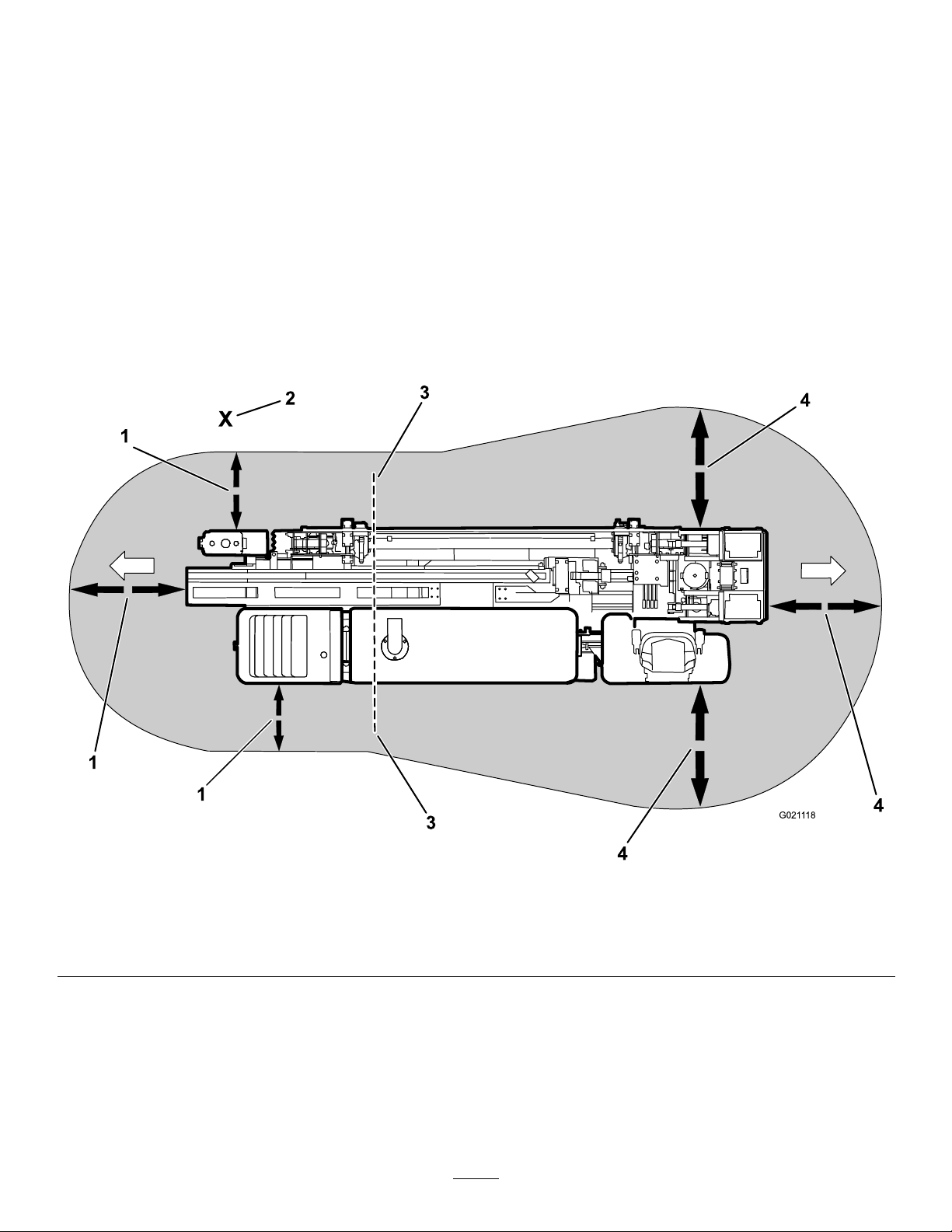
•Operatethedrivependantalongsidethemachineoutside
ofthedangerzone(Figure3).
•Keepallbystandersawaywhilemovingthemachine.
•Donotcarrypassengersonthemachine.
•Watchfortheturning-radiussweepofthedrillframe,as
thecenteroftheturningradiusistheendofthetrack.
•Movingthemachinewiththetetheredremotecan
beerratic;moveslowlywhenusingtheremotefor
movement.
•Usecarewhenloadingorunloadingthemachineontoa
trailer.
•Watchfortrafcwhencrossingroadways.
•Checkforoverheadclearances(i.e.branches,doorways,
electricalwires)beforedrivingunderanyobjectsanddo
notcontactthem.
•Whendrivingonaslope,theoperatorshouldbeup-slope
fromthemachine.
Thefollowingillustrationdisplaysthesafedistancethatall
individualsmustmaintainwhilemovingthemachine.
Figure3
DrivingDangerZone
1.1.8m(6ft)safetydistance
2.Operator4.2.4m(8ft)safetydistance
3.Turning-radiuscenter
5
Page 6
DrillingSafety
1
2
3
1
G021 117
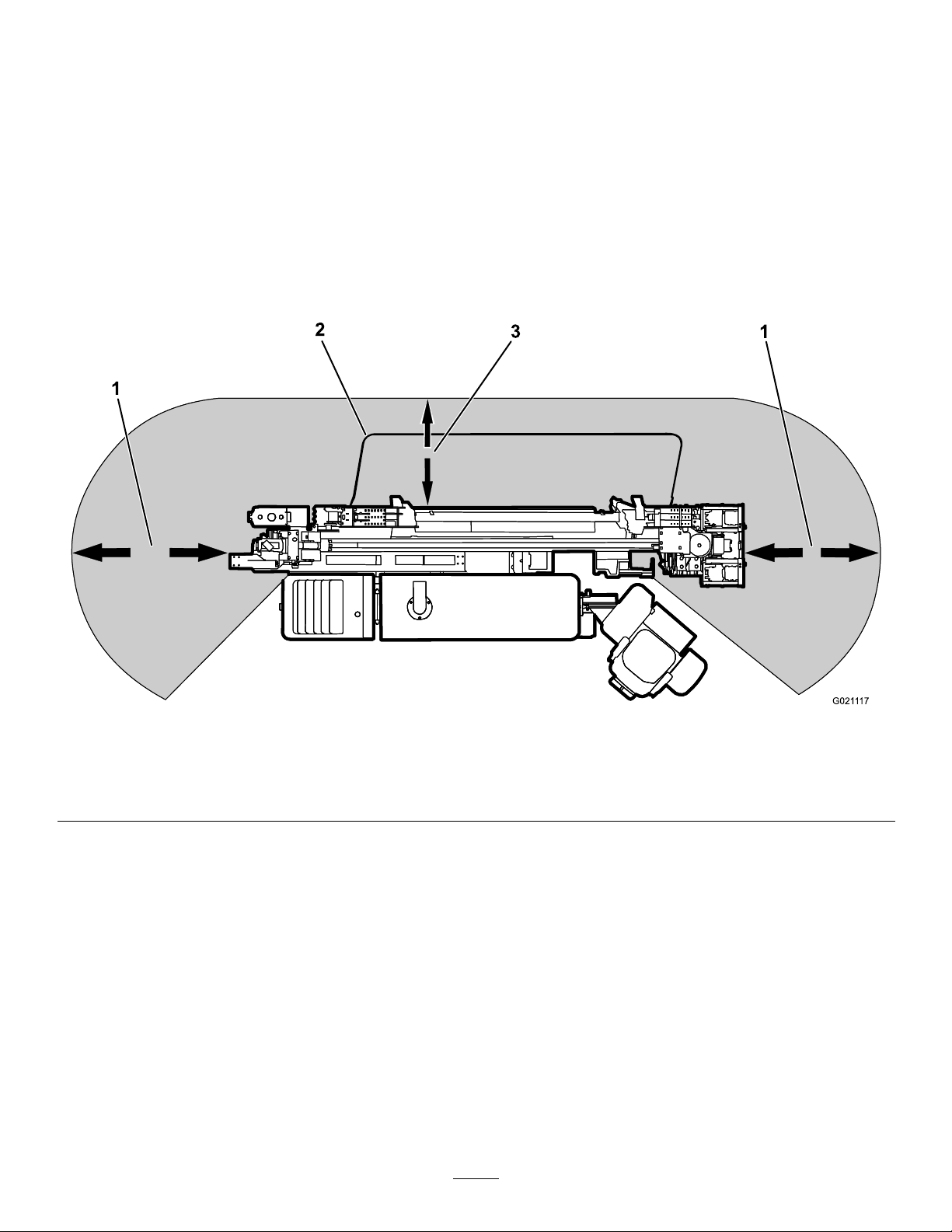
•Alwayslowerthesafetybarbeforedrilling(Figure4).
•Ensurethatnooneapproachesapipewhileitisspinning.
Thepipecansnagonclothingandcauseamputation
ordeath.AlwaysengagetheExit-sideLockoutbefore
anyoneapproachesthefrontofthemachine,bit,reamer,
orpipe.
DrillingDangerZone
Thedangerzoneistheareawithinandaroundthemachine
whereapersonisexposedtotheriskofinjury.Thisproximity
includeswhereapersoncanbereachedbyoperational
movementofthemachine,itsworkingdevices,auxiliary
equipment,orswinging/fallingequipment.
Note:Thedangerzonedenestheamountofspace
neededforsafedrillingoperation,includingmovementof
thecarriage.
Thefollowingillustrationdisplaysthesafedistancethatmust
bekeptbyallindividualswhiledrilling.
Figure4
DrillingDangerZone
1.3m(10ft)safetydistance3.1.8m(6ft)safetydistance
2.Safetybar
DrillingNearUtilityLines
Whenworkingnearburiedutilitylines,safetyprecautions
mustbetaken.
Important:Beforeoperatinginanareawith
high-voltagelinesorcables,contacta“One-Call
SystemDirectory”service.IntheUSA,call811or
yourlocalutilitycompany .Ifyoudonotknowyour
localutilitycompany’sphonenumber,callthenational
number(USAandCanadaonly)at1-888-258-0808.Also,
contactanyutilitycompaniesthatarenotparticipants
ofthe“One-CallSystemDirectory”service.Please
refertoDrillingNearUtilityLines(page6)formore
information.
6
Page 7
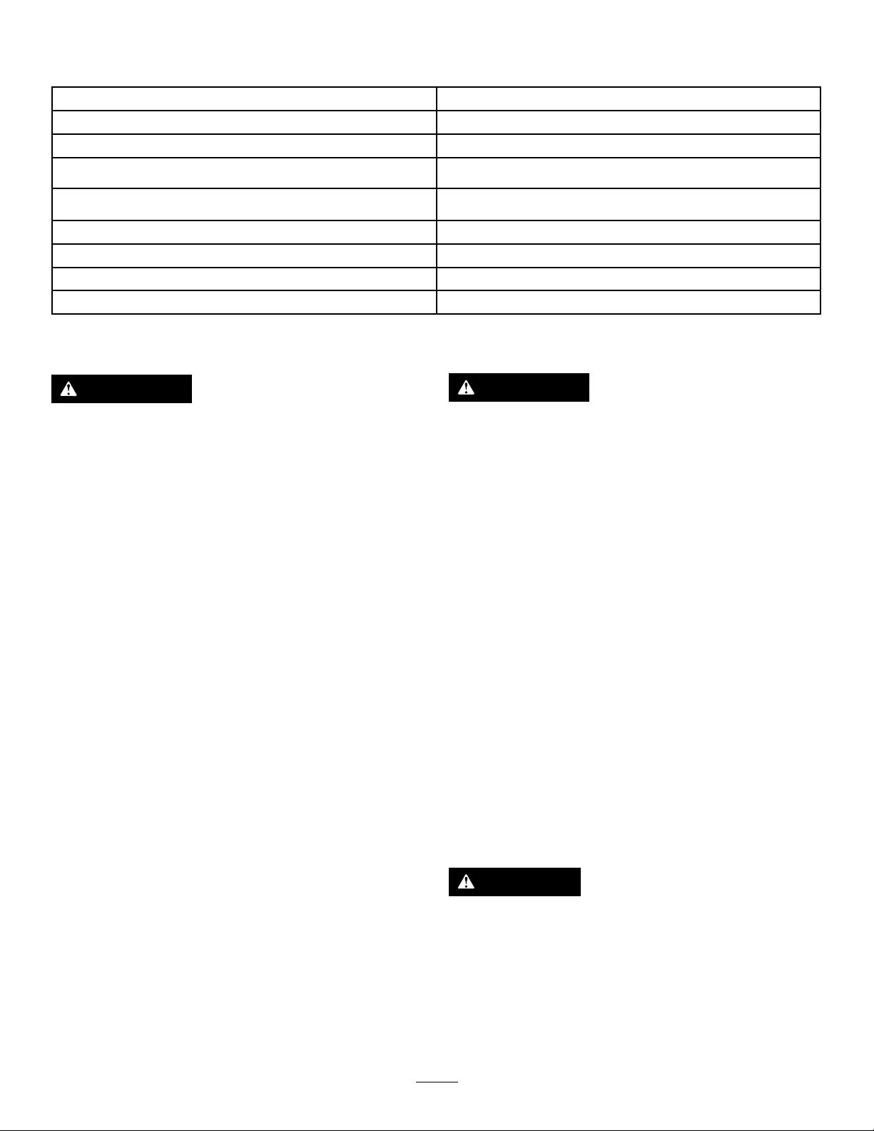
UtilityLineColor
Refertothefollowingtablefortheproperutilitylineandthecorrespondingutilitylinecolor(USAandCanada).
UtilityLine
ElectricRed
Telecommunication,alarmorsignal,cables,orconduit
Naturalgas,oil,steam,petroleum,orothergaseousorammable
material
SeweranddrainGreen
DrinkingwaterBlue
Reclaimedwater,irrigation,andslurrylinesPurple
TemporarysurveymarkingsPink
ProposedexcavationlimitsWhite
ElectricalLineSafety
WARNING
Ifyouleavetheseatofthemachineortouch
anypartofthemachinewhenitischargedwith
electricity,seriousinjuryordeathcouldresult.
Donotleavetheseatofthemachineifthemachine
ischargedwithelectricity .
Intheeventofanelectricstrikethatchargesthemachine,the
Zap-AlertElectricStrikealarmsystemwillsoundforaslong
asthemachineischargedwithpower.
Note:Immediatelycontacttheproperemergencyandutility
authoritiestosecuretheareainthecasethatthemachineis
chargedandyoucannotleavetheseatofthemachine.
Note:Itispossibletostrikeautilitylinewithoutthemachine
becomingcharged.
•Thealarmwillsoundifthedrillcontactsanelectrical
powersource.
•Itislikely(butnotalwaysthecase)thatthepower-source
interrupterorbreakerwilltrip,buttoensureyoursafety,
considerthatthemachinemaybeconductingelectricity.
•Donotattempttoleavethemachine.
Note:Youwillbesafeaslongasyoudonotleavethe
seatofthemachine.
UtilityLineColor
Orange
Yellow
GasLineSafety
WARNING
Ifyoudamageagasline,animmediateexplosion
andrehazardcouldoccur.Leakinggasisboth
ammableandexplosiveandmaycauseserious
injuryordeath.
•Donotsmokewhileoperatingthemachine.
•Shutoffthemachineandremovethekey.
•Removeallindividualsfromtheworkarea.
•Immediatelycontacttheproperemergencyand
utilityauthoritiestosecurethearea.
WaterLineSafety
Ifyoudamageawaterline,apotentialoodhazard
couldoccur.
•Shutoffthemachineandremovethekey .
•Removeallindividualsfromtheworkarea.
•Immediatelycontacttheproperemergencyand
utilityauthoritiestosecurethearea.
CommunicationLineSafety
Important:RefertoElectricalLineSafety(page7)ifa
communicationlineisdamaged.
•Touchinganypartofthemachinemaygroundyou.
•Donotallowanotherindividualtotouchorapproach
themachinewhencharged.
•Thealarmmaysoundifacommunicationlineisbroken,
butuntilyouarecertain,youmustconsiderthealarmto
beanelectricstrike.
CAUTION
Ifyoudamagetheber-opticcableandlookinto
theexposedhighly-intenselight,youmayharm
youreyes.
•Shutoffthemachineandremovethekey.
•Removeallindividualsfromtheworkarea.
•Immediatelycontacttheproperemergencyand
utilityauthoritiestosecurethearea.
7
Page 8

MaintenanceandStorage
•Donottouchpartswhichmaybehotfromoperation.
Allowthemtocoolbeforeattemptingtomaintain,adjust,
orservice.
•Lowerthethrustframe,stoptheengine,andremove
thekey.Waitforallmovementtostopbeforeadjusting,
cleaning,orrepairing.
•Cleandebrisfromattachments,drives,mufers,and
enginetohelppreventres.Cleanupoilorfuelspillage.
•Lettheenginecoolbeforestoringanddonotstorenear
ame.
•Donotstorefuelnearamesordrainindoors.
•Parkthemachineonlevelground.
•Donotallowuntrainedpersonneltoservicethemachine.
•Carefullyreleasepressurefromcomponentswithstored
energy.
–Donotrefuelthemachineindoors.
–Donotstorethemachineorfuelcontainerinside
wherethereisanopename,suchasnearawater
heaterorfurnace.
–Donotllacontainerwhileitisinsideavehicle,
trunk,pick-upbed,oranysurfaceotherthanthe
ground.
–Keepcontainernozzleincontactwiththetankduring
lling.
•UseonlygenuineTororeplacementpartstoensurethat
originalstandardsaremaintained.
•Keepyourbodyandhandsawayfrompinholeleaks
ornozzlesthatejecthighpressurehydraulicuid.Use
cardboardorpapertondhydraulicleaks;donotuse
yourhands.Hydraulicuidescapingunderpressurecan
penetrateskinandcauseinjuryrequiringsurgerywithina
fewhoursbyaqualiedsurgeonorgangrenemayresult.
•Keephandsandfeetawayfrommovingparts.Ifpossible,
donotmakeadjustmentswiththeenginerunning.
•Disconnectthebatterybeforemakinganyrepairs.
Disconnectthenegativeterminalrstandthepositive
last.Reconnectpositiverstandnegativelast.
•Chargebatteriesinanopen,wellventilatedarea,away
fromsparkandames.Unplugthechargerbefore
connectingordisconnectingitfromthebattery.W ear
protectiveclothinganduseinsulatedtools.
•Batteryacidispoisonousandcancauseburns.Avoid
contactwithskin,eyes,andclothing.Protectyourface,
eyes,andclothingwhenworkingwithabattery.
•Batterygasescanexplode.Keepcigarettes,sparksand
amesawayfromthebattery.
•Keepallpartsingood-workingconditionandallhardware
tightened.Replaceallwornordamageddecals.
•Ifanymaintenanceorrepairrequirestheframetobe
intheraisedposition,securetheframeintheraised
positionwiththehydrauliccylinderlock;refertoUsing
theCylinderLock(page74).
•Keepnutsandboltstight.
NoiseandVibrationLevels
WARNING
Theoperatormustwearhearingprotectionwhen
operatingthemachine.Failuretowearhearing
protectionmaycausehearingimpairment.
SoundPressureLevel
Thisunithasasoundpressurelevelattheoperator’searof92
dBA,whichincludesanUncertaintyValue(K)of1dBA.
Soundpressurelevelwasdeterminedaccordingtothe
proceduresoutlinedinEN791.
SoundPower
Thisunithasaguaranteedsoundpowerlevelof113dBA,
whichincludesanUncertaintyValue(K)of3.75dBA.
Thesoundpowerlevelwasdeterminedaccordingtothe
proceduresoutlinedinISO4871.
•Keepequipmentingoodcondition.
•Donottamperwithsafetydevices.
•Keepthemachinefreeofgrass,leaves,orotherdebris
build-up.Cleanupoilorfuelspillage.Allowthemachine
tocoolbeforestoring.
•Useextracarewhenhandlingfuels.Theyareammable
andvaporsareexplosive.
–Useonlyanapprovedcontainer.
–Donotremovethefuelcaporaddfuelwhenthe
engineisrunning.Allowtheenginetocoolbefore
refueling.Donotsmoke.
VibrationLevel
Measuredvibrationlevelforrighthand=0.3m/s
Measuredvibrationlevelforlefthand=0.8m/s
Measuredvibrationlevelforwholebody=0.17m/s
UncertaintyValue(K)=0.08m/s
Measuredvaluesweredeterminedaccordingtotheprocedures
outlinedinENISO20643.
8
2
2
2
2
Page 9
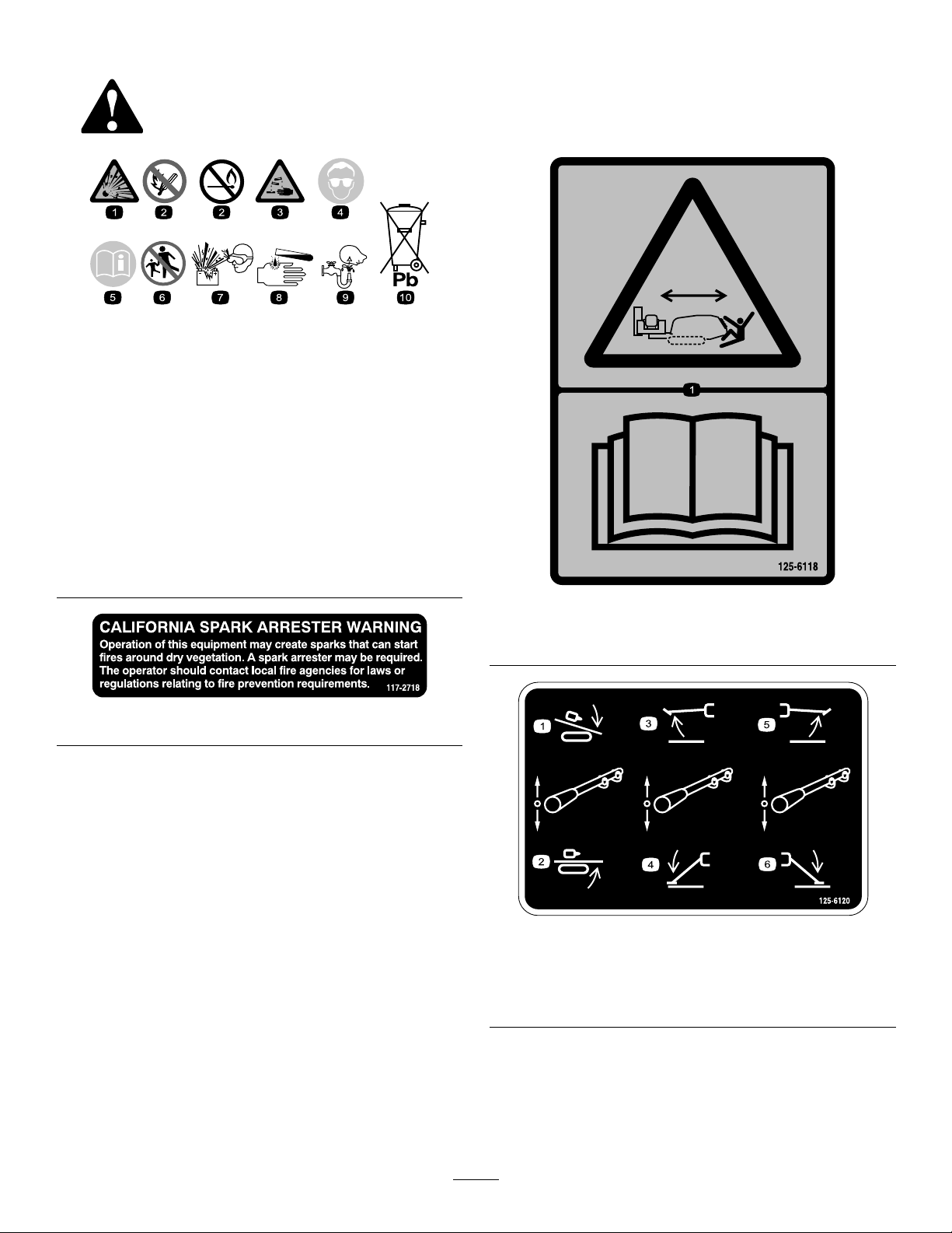
SafetyandInstructionalDecals
Safetydecalsandinstructionsareeasilyvisibletotheoperatorandarelocatednearanyareaofpotential
danger.Replaceanydecalthatisdamagedorlost.
BatterySymbols
Someorallofthesesymbolsareonyourbattery
1.Explosionhazard
2.Nore,opename,or
smoking.
3.Causticliquid/chemical
burnhazard
4.Weareyeprotection9.Flusheyesimmediately
5.ReadtheOperator's
Manual.
6.Keepbystandersasafe
7.Weareyeprotection;
8.Batteryacidcancause
10.Containslead;donot
117-2718
distancefromthebattery.
explosivegasescan
causeblindnessandother
injuries
blindnessorsevereburns.
withwaterandgetmedical
helpfast.
discard.
125-6118
1.Crushinghazard,machinemovement—readtheOperator’s
Manual.
125-6120
1.Raisedrillcarriage
2.Lowerdrillcarriage5.Raiserightstabilizer
3.Raiseleftstabilizer
9
4.Lowerleftstabilizer
6.Lowerrightstabilizer
Page 10
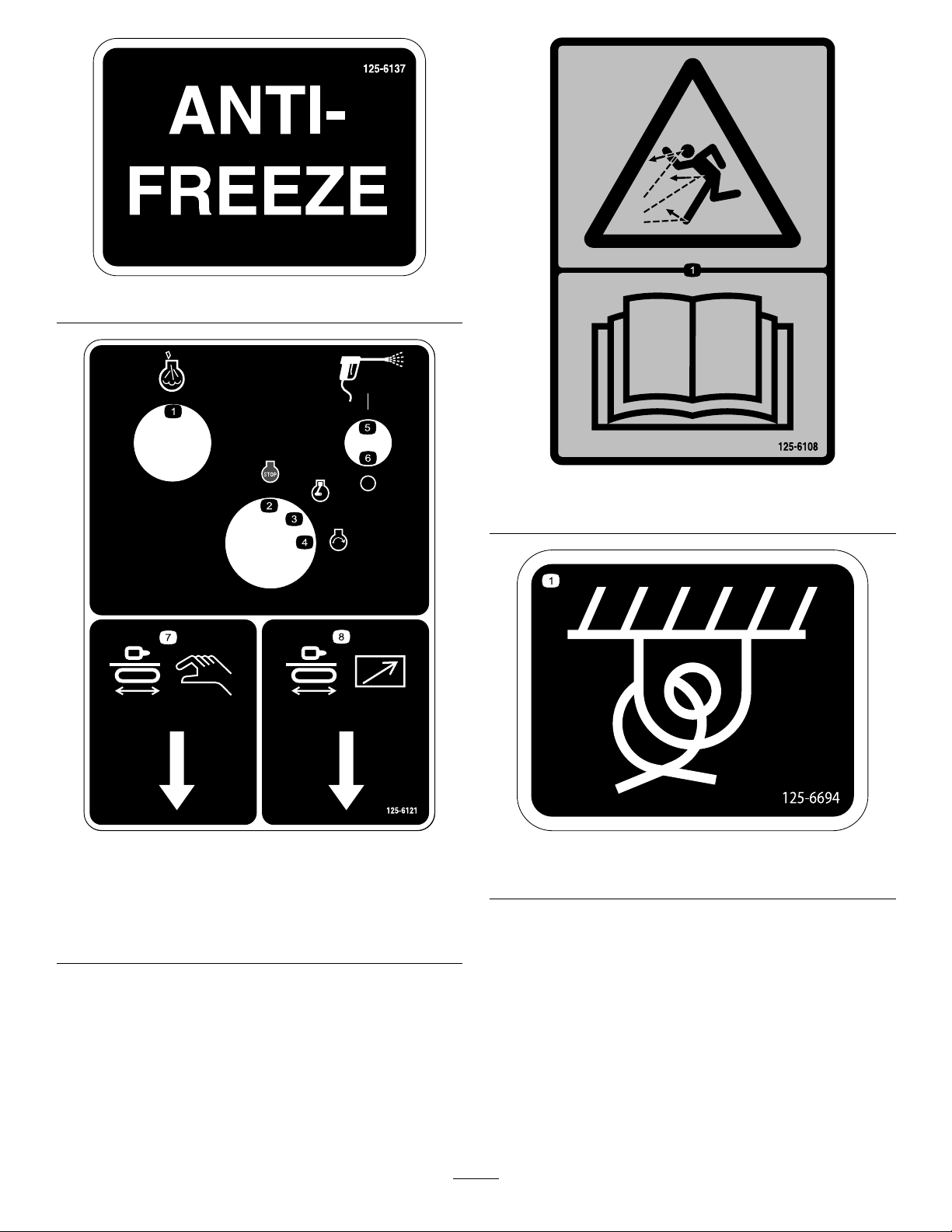
125-6137
125-6108
1.Thrownobjecthazard—readtheOperator’sManual.
125-6121
1.Engine—heatinglight5.Fluidpumpon
2.Engine—stop
3.Engine—run7.Drill-pendantreceptacle
4.Engine—start8.Drive-pendantreceptacle
6.Fluidpumpoff
125-6694
1.Tie-downpoint
10
Page 11
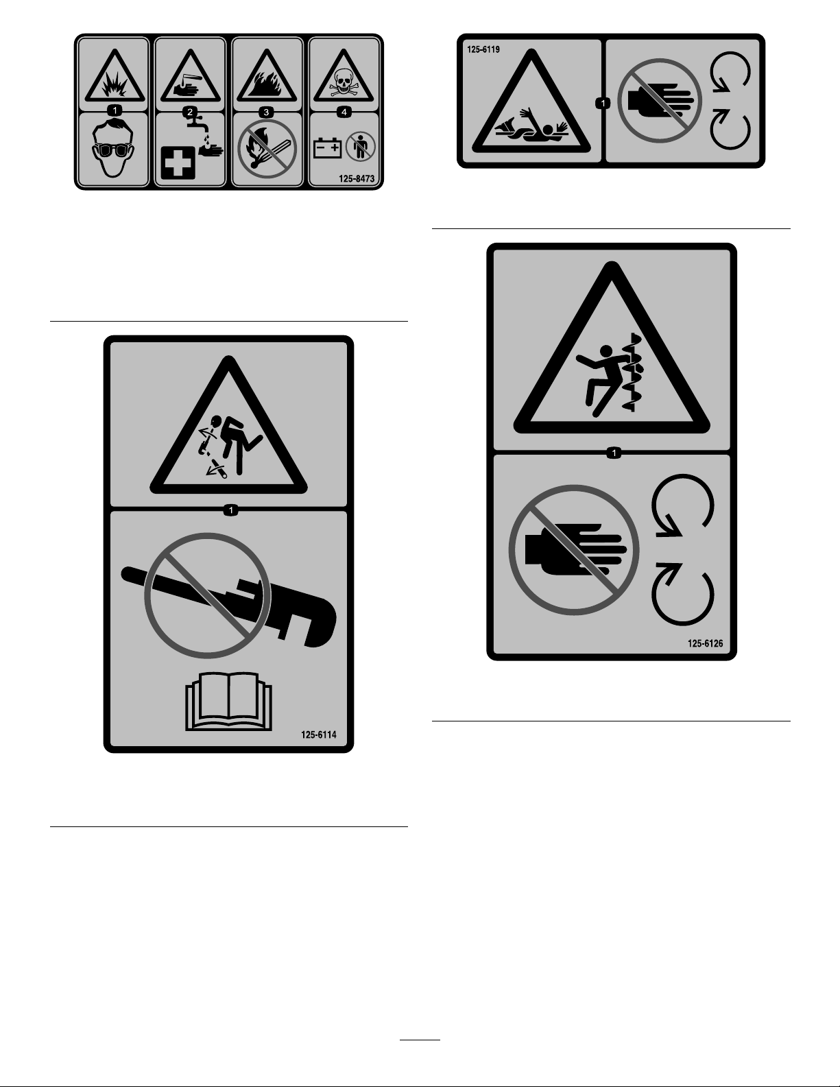
1.Explosionhazard—wear
eyeprotection.
2.Causticliquid/chemical
burnhazard—rinse
affectedareaandseek
medicalassistance.
125-8473
3.Firehazard—keepopen
amesaway.
4.Poisonhazard—donot
tamperwiththebattery.
125-6119
1.Entanglementhazard—keepawayfrommovingobjects.
125-6114
1.Storedenergyhazard—donotusetools;readthe
Operator’sManual.
125-6126
1.Entanglementhazard—keepawayfrommovingparts.
11
Page 12
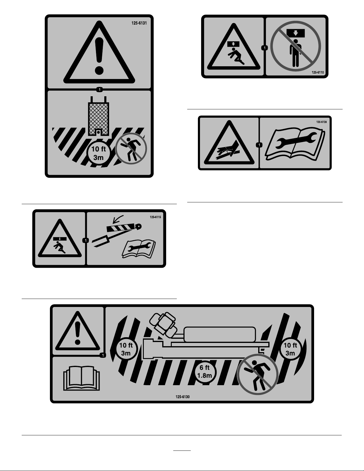
125-6131
1.Warning—stayatleast3m(10ft)awayfromthemachine.
125-6110
1.Crushinghazard—donotstandunderanypartofthe
machine.
125-6128
1.Highpressureuidhazard,injectionintothebody—read
theOperator’sManualbeforeperformingmaintenance.
125-6115
1.Crushinghazard—deploycylinderlocksbeforeperforming
maintenance.
125-6130
1.Warning—readtheOperator’sManual;stayatleast3m(10ft)awayfromthefrontandrearofthemachineand1.8m(6ft)
awayfromthesidesofthemachine.
12
Page 13
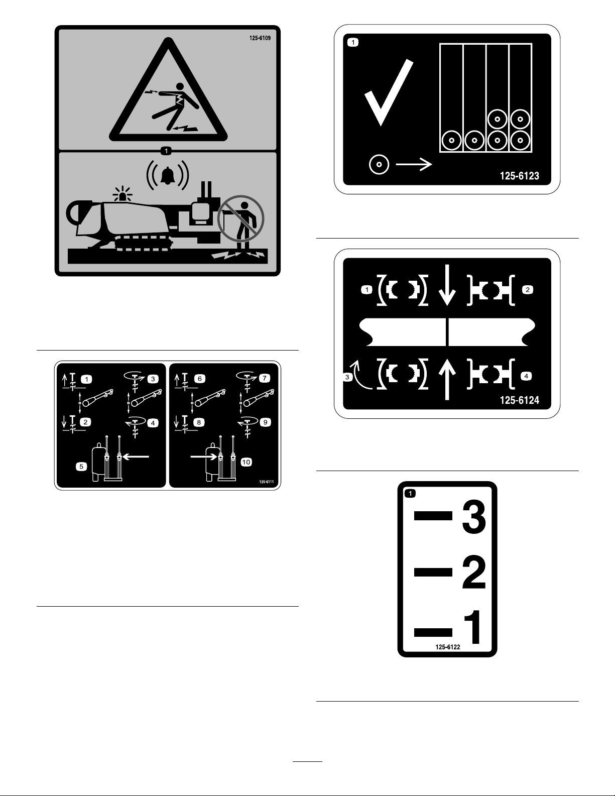
125-6109
1.Electricalshockhazard—whentheZap-Alertsystemis
activatedbyapowerstrike,donotleavetheoperator’s
positionortouchthegroundandthemachineatthesame
time;themachinewillbeenergizedwithelectricalpower .
125-6123
1.Loadpipesfrombackrowrst.
125-6124
1.Centerthepipejointbetweentheupperandlower
wrenches.
125-6111
1.Stakeup6.Stakeup
2.Stakedown7.Stakespin
3.Stakespin
counterclockwise
4.Stakespinclockwise9.Stakespinclockwise
5.Leftstake
counterclockwise
8.Stakedown
10.Rightstake
125-6122
1.Piperow
13
Page 14
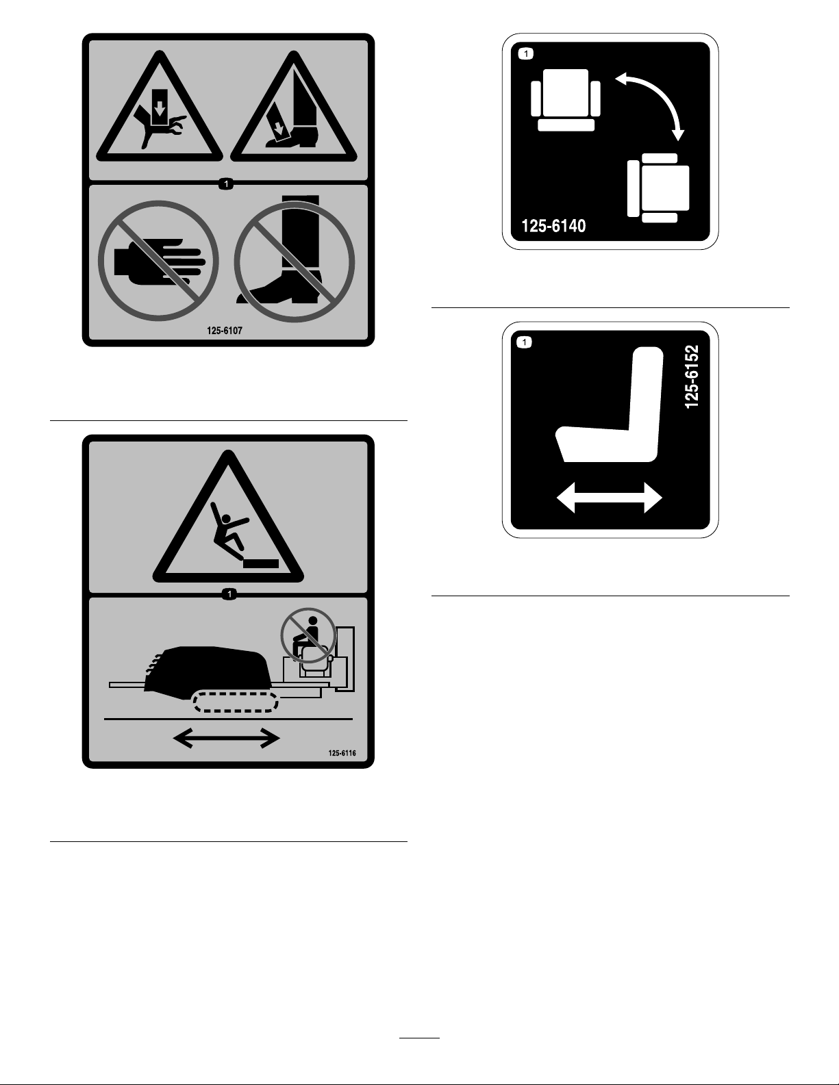
125-6107
1.Crushinghazardofhandandfoot—keephandsandfeet
away.
125-6140
1.Rotatethechair.
125-6152
1.Moveseatforwardsandbackwards.
125-6116
1.Fallinghazard—donotmovethemachinewhensomeone
isintheoperator’sposition.
14
Page 15
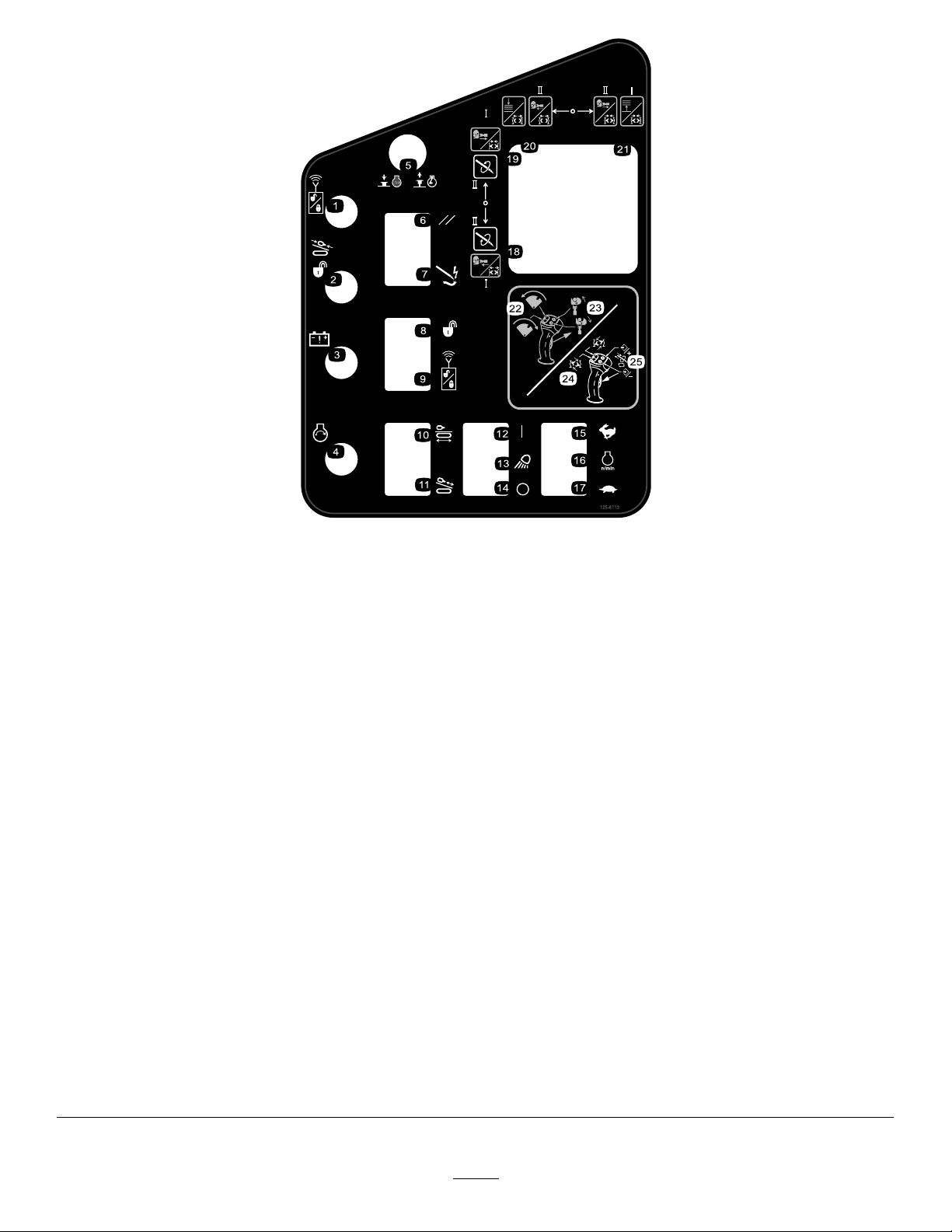
125-6112
1.Exit-sidelockout—resetlight
2.Exit-sidelockout—drill-enabledlight15.Pressandholdtoincreaseenginespeed.
3.Receiver-battery-statuslight16.Enginespeed
4.Engine—start17.Pressandholdtodecreaseenginespeed.
5.Pressdowntostoptheengine;pulluptostarttheengine.
6.ResetZap-Alertsystem
7.Zap-Alertsystemtriggered
8.Unlockexit-sidelockout
9.Resetexit-sidelockout
10.Engagedrivemovementandsetupfunctions
11.Engagedrillcarriagemovementandotherdrillfunctions24.Withtriggerpressed,rockforwardtorotatetheupperwrench
12.Worklights—On25.Withtriggerpressed,pressfrontorrearbuttontoresume
13.Worklights
14.Worklights—Off
18.ModeI—lefttriggerreleased,extendspipegrippertoward
drillframe;lefttriggerpressed,openslowerwrench.Mode
II—spindrillspindleclockwise.
19.ModeI—lefttriggerreleased,extendspipegrippertoward
pipeholder;lefttriggerpressed,closeslowerwrench.Mode
II—spindrillspindlecounterclockwise.
20.ModeI—lefttriggerreleased,lowerspipeelevator;lefttrigger
pressed,opensupperwrench.ModeII—lefttriggerreleased,
extendspipegrippertowarddrillframe;lefttriggerpressed,
opensupperwrench.
21.ModeI—lefttriggerreleased,raisespipeelevator;lefttrigger
pressed,closesupperwrench.ModeII—lefttriggerreleased,
extendspipegrippertowardpipeholder;lefttriggerpressed,
closesupperwrench.
22.Withtriggerreleased,rockforwardtorotatepipeloader
towardpipecam,rockbackwardtorotatepipeloadertoward
drillframe.
23.Withtriggerreleased,upperbuttonclosespipegripper,lower
buttonopenspipegripper.
counterclockwisetoloosenajoint;rockrearwardtorotatethe
upperwrenchclockwisetotightenajoint.
thepreviouslysetauto-drillspeed;pressandholdthefront
buttontoincreasetheauto-drillspeed;pressandholdthe
rearbuttontodecreasetheauto-drillspeed.
15
Page 16
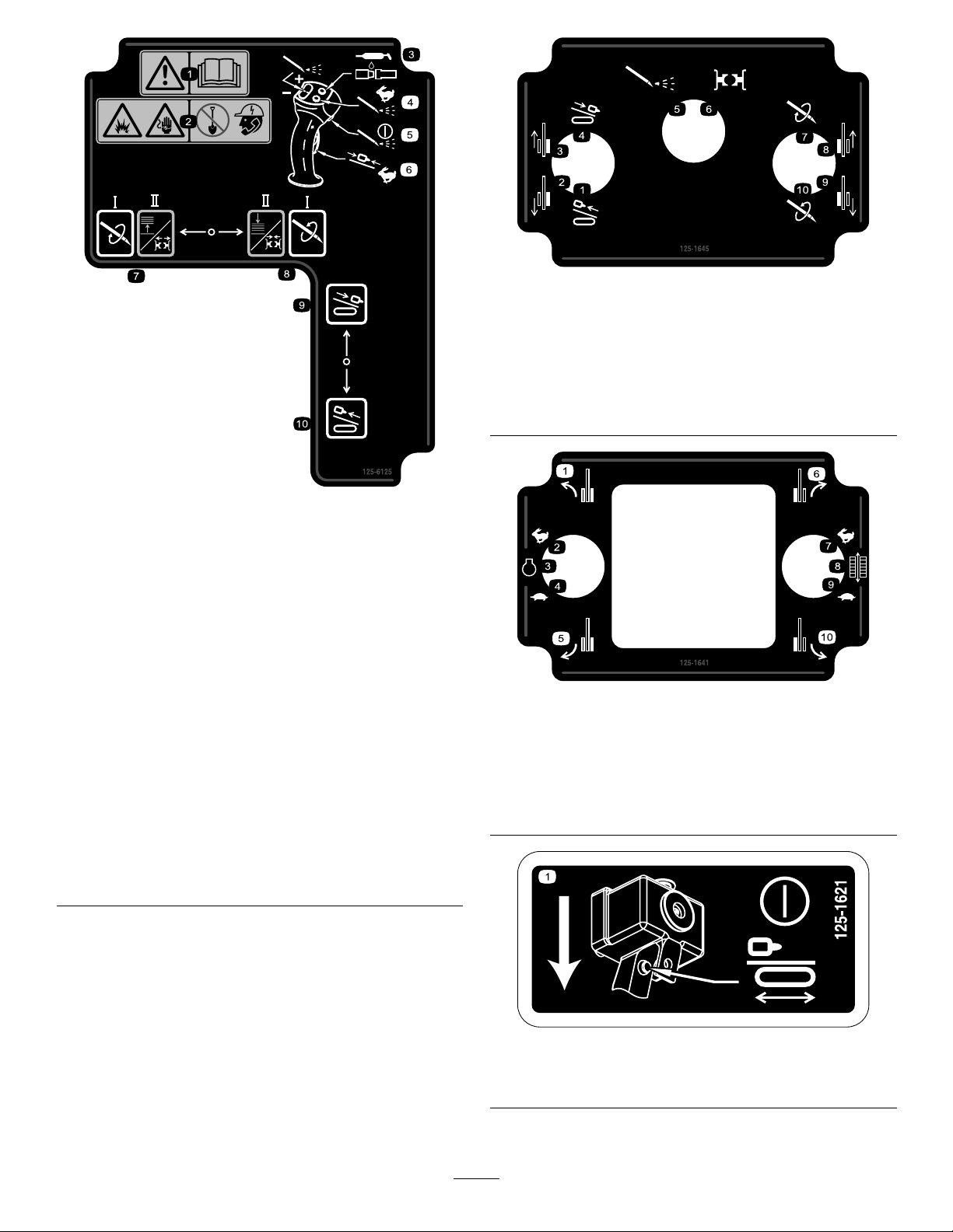
125-1645
1.Pullbackdrillcarriage6.Wrenchcontrolson
2.Reverselefttrack
3.Forwardlefttrack
4.Forwarddrillcarriage9.Reverserighttrack
5.Drilluidpumpon
7.Drillspindleclockwisespin
8.Forwardrighttrack
10.Drillspindle
counterclockwisespin
125-6125
1.Warning—readthe
Operator’sManual.
2.Explosionhazard;
electricalshock
hazard—donotdigbefore
callinglocalservices.
3.Presstoapplytread-joint
compound.
4.Pressandholdfor
maximumdrillinguid
pressure;releasetostop
theow .
5.Presstoturnthe
drilling-uidpumpon
oroff.
6.Pressandholdtomove
thedrillcarriageathigh
speedupordownthedrill
frame.
7.ModeI—spindrillspindle
clockwise.ModeII—left
triggerpressed,openthe
lowerwrench;lefttrigger
released,raisethepipe
elevator.
8.ModeI—spindrillspindle
counterclockwise.Mode
II—lefttriggerpressed,
closethelowerwrench;
lefttriggerreleased,lower
thepipeelevator .
9.Thrustthedrillcarriage
forward.
10.Pullthedrillcarriage
rearward.
125-1641
1.Forwardleft
2.Increaserpm7.High
3.Enginespeed8.Trackspeed
4.Decreaserpm9.Low
5.Reverseleft
6.Forwardright
10.Reverseright
125-1621
1.Presstheoperatorpresenceswitchtoenablemachine
movement.
16
Page 17
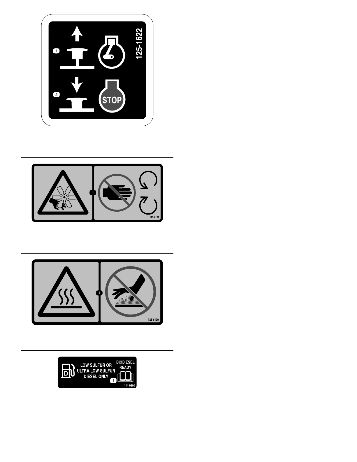
125-1622
1.Pulluptostarttheengine.2.Pushdowntostopthe
engine.
125-6127
1.Cutting/dismembermenthazard,fan—keepawayfrom
movingparts.
125-6129
1.Hotsurface—keepawayfromhotsurfaces.
114-9600
1.ReadtheOperator'sManual.
17
Page 18
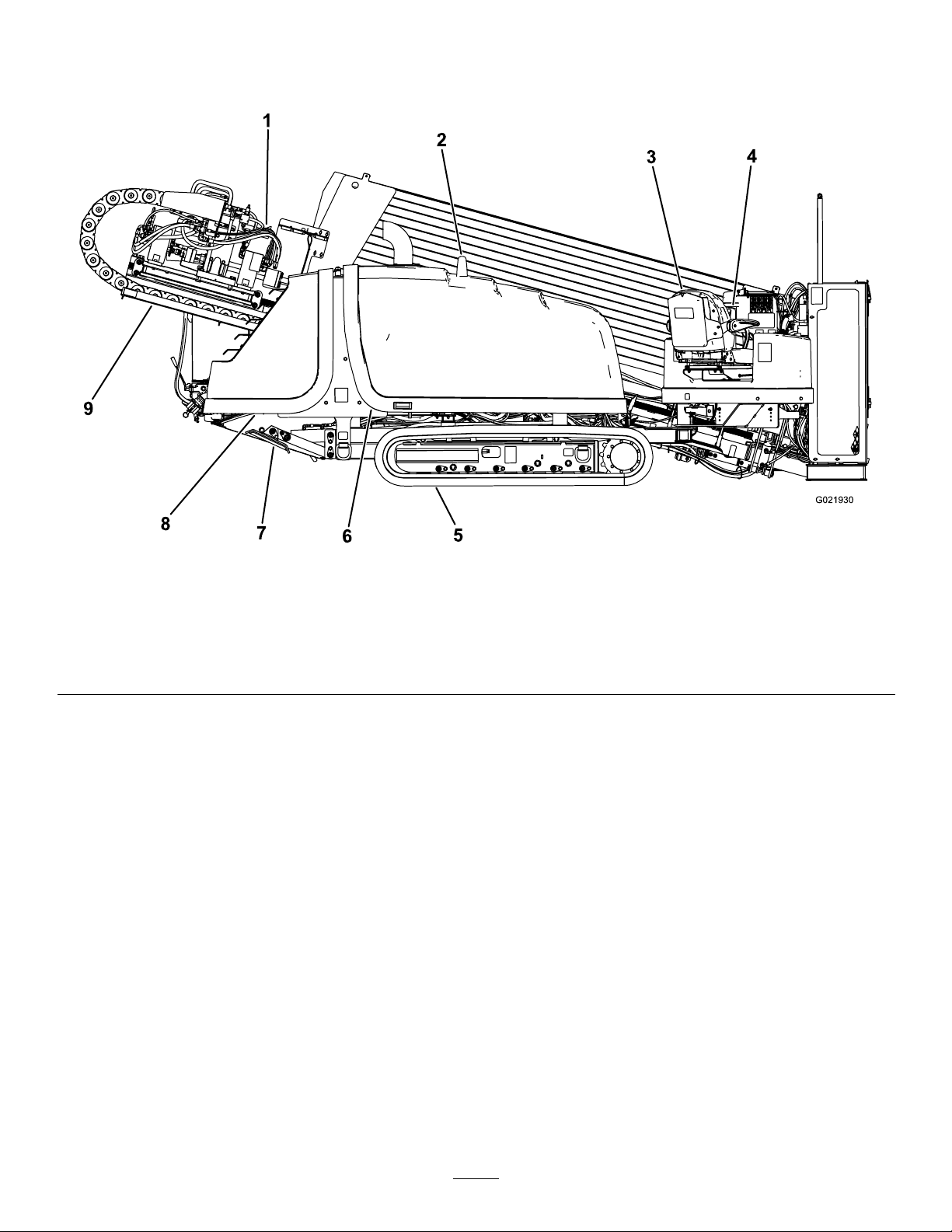
ProductOverview
Figure5
1.Drillcarriage6.Fronthood
2.Zap-alertstrobe7.Rightstabilizer
3.Operatorseat
4.Controlpanel9.Thrustframe
5.Track
8.Rearhood
18
Page 19

Figure6
1.Stake-downcage
2.Pipeholder
3.Safetybar7.Stake-downplate
4.Drilling-uid-pumpinlet
5.Rear-controlpanel
6.Leftstabilizer
19
Page 20
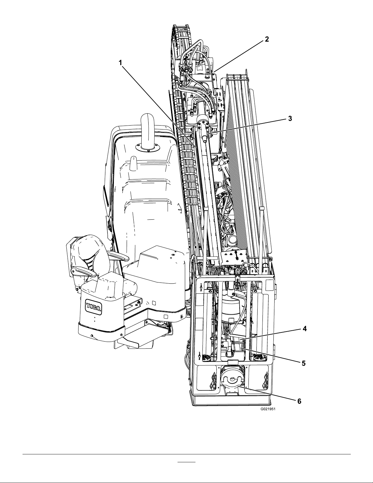
Figure7
1.Thrustframe
2.Drillcarriage5.Lowerwrench
3.Drillspindle6.Pipewiper
4.Upperwrench
20
Page 21

Controls
Refertothefollowingsectionsfortheappropriatemachine
controls:
•OperatorPlatform
•Monitor
•ControlPanel
•LeftJoystick—ModeI
•LeftJoystick—ModeII
•RightJoystick—ModeI
•RightJoystick—ModeII
•Exit-Side-LockoutSystem(StandardRange)
•Exit-Side-LockoutSystem(LongRange)
•RearControlPanel
•DrillFrameandStabilizerControls
•DrivePendant
•DrillPendant
•Stake-DownLevers
Operator-ControlsCovers
Thecoversprotecttheoperatorcontrolsfromadverse
weatherconditions,suchasrain,wind,sunlight,etc.Remove
thembeforeusingthemachineandreplacethembefore
leavingthemachinefortheday.Eachcoverissecuredwith2
screwsasshowninFigure9.
•Battery-DisconnectSwitch
OperatorPlatform
Theoperatorplatform,locatedontheright,frontcornerof
themachine,containsmostofthecontrolsyouusetooperate
thedrillingfunctionsofthemachine.
Figure8
Figure9
1.Screws2.Covers
Operator-PlatformLatch
Theoperatorplatformswingsoutawayfromthemachine,
makingroomforyoutosit.Ithas4positions:travel(swung
allthewayintothemachine),full-out,and2intermediate
positions.ReturntheplatformtotheTRA VELpositionbefore
movingthemachine.
Toreleasetheplatformandswingitoutorin,pressdownon
therearplatformlatch(Figure10).
1.Operatordisplay
2.Leftcontrolpaneland
joystick
3.Rightjoystick
Figure10
1.Rearplatformlatch
21
Page 22
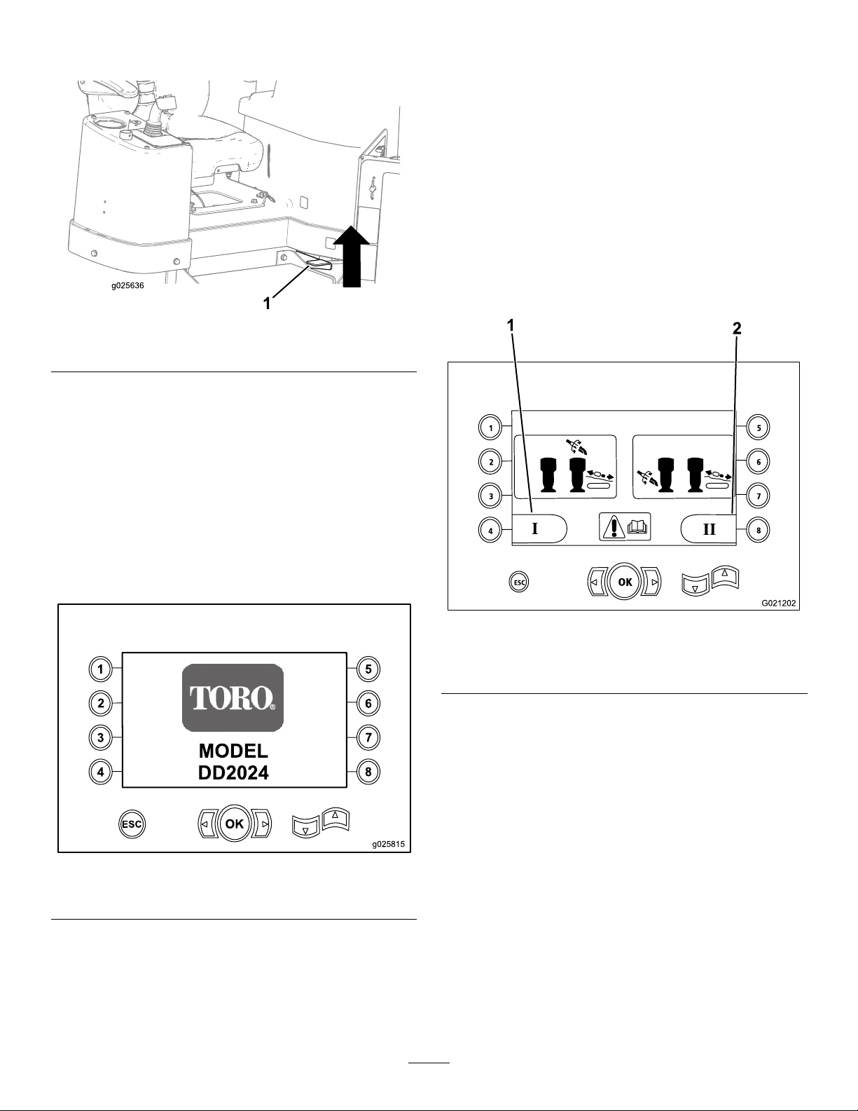
Toreleasetheplatformandswingitoutorin,pressuponthe
1
2
3
4
5
6
7
8
OK
ESC
DD2024
g025815
frontplatformlatch(Figure11).
Figure11
1.Frontplatformlatch
Monitor
Start-upScreen
Control-selectScreen
Whenyoupowerupthemachine,thisisthescreenthat
appearsafterthestart-upscreen.
The2controllayoutsthattheoperatorcanchoosefrom
consistofthefollowing:
•ModeI—Placesthedrillingfunctionsonrightjoystick,
whiletheleftjoystickoperatesthepipeloaderandthe
wrenchfunctions(Figure13)
Pressbuttonnumber4toselectthisfunction(Figure13).
•ModeII—Thisfunctionsplitsthedrilling,wrench,and
pipeloadingbetweentheleftandrightjoysticks(Figure
13)
Pressbuttonnumber8toselectthisfunction(Figure13).
Whenyoupowerupthemachine,thisistherstscreenthat
appears(Figure12).
Thestart-upscreenappearswheneveryoupresstheESC
button(foundinthebottom-leftcornerofthescreen)from
therst3pagesofthedisplay.
Note:Nokeysareactivefromthisscreen.
Figure12
Start-upScreen
Figure13
Control-selectScreen
1.ModeI2.ModeII
Note:Ifaselectionisnotmadewithin5seconds,thescreen
willdefaulttotheprevioussettingandwillgototheMain
OperatingScreen(page23).
22
Page 23
Machine-informationScreen
1
ESC
2
3
4
5
6
7
8
OK
6
12
18
24
30
n/min
x 100
G0 2124 6
4
1
2
3
5
MainOperatingScreen
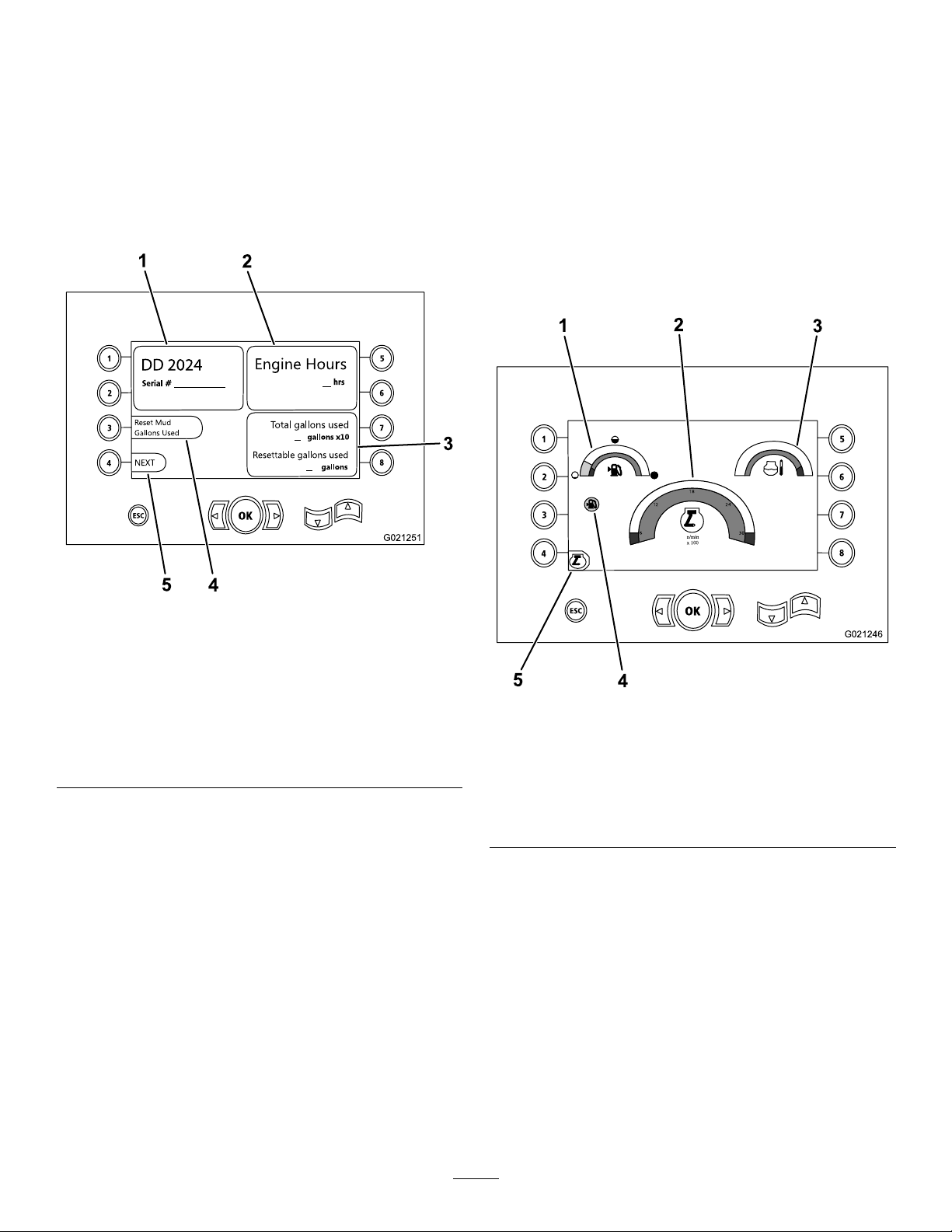
Thisscreencontainsthefollowinginformation:
•Themachinemodelandserialnumber(Figure14).
•Thenumberofenginehoursforthemachine(Figure14).
•Thenumberofdrillinguid-gallonsusedandthenumber
ofre-settabledrilling-uidgallonsused(Figure14).
Note:Pressbutton3toresetthenumberofdrilling-uid
gallonssincethelastreset(Figure14).
Toaccessthisscreen,pressbutton4orthedownarrowon
theMachine-informationScreen(page23).
Themainoperatingscreendisplaystheengine-rpmgauge,
thefuel-quantitygauge,andtheengine-temperaturegauge
(Figure15).
Thelow-fuelindicatorlightsuponthemainoperatingscreen
whenthemachineisrunninglowonfuel(Figure15).
Pressbuttonnumber4toselectthehorsepowercontrol
(Figure15).
1.Modelandmachineserial
number
2.Numberofenginehours
3.Totalnumberof
drilling-uidgallonsused
andresettabledrilling-uid
gallonsused
Machine-informationScreen
Figure14
4.Resetdrilling-uidgallons
used
5.Nextscreen
1.Fuelgauge
2.Engine-speed(rpm)gauge
3.Coolant-temperature
gauge
Figure15
MainOperatingScreen
4.Low-fuelindicator
5.Horsepowercontrol
23
Page 24
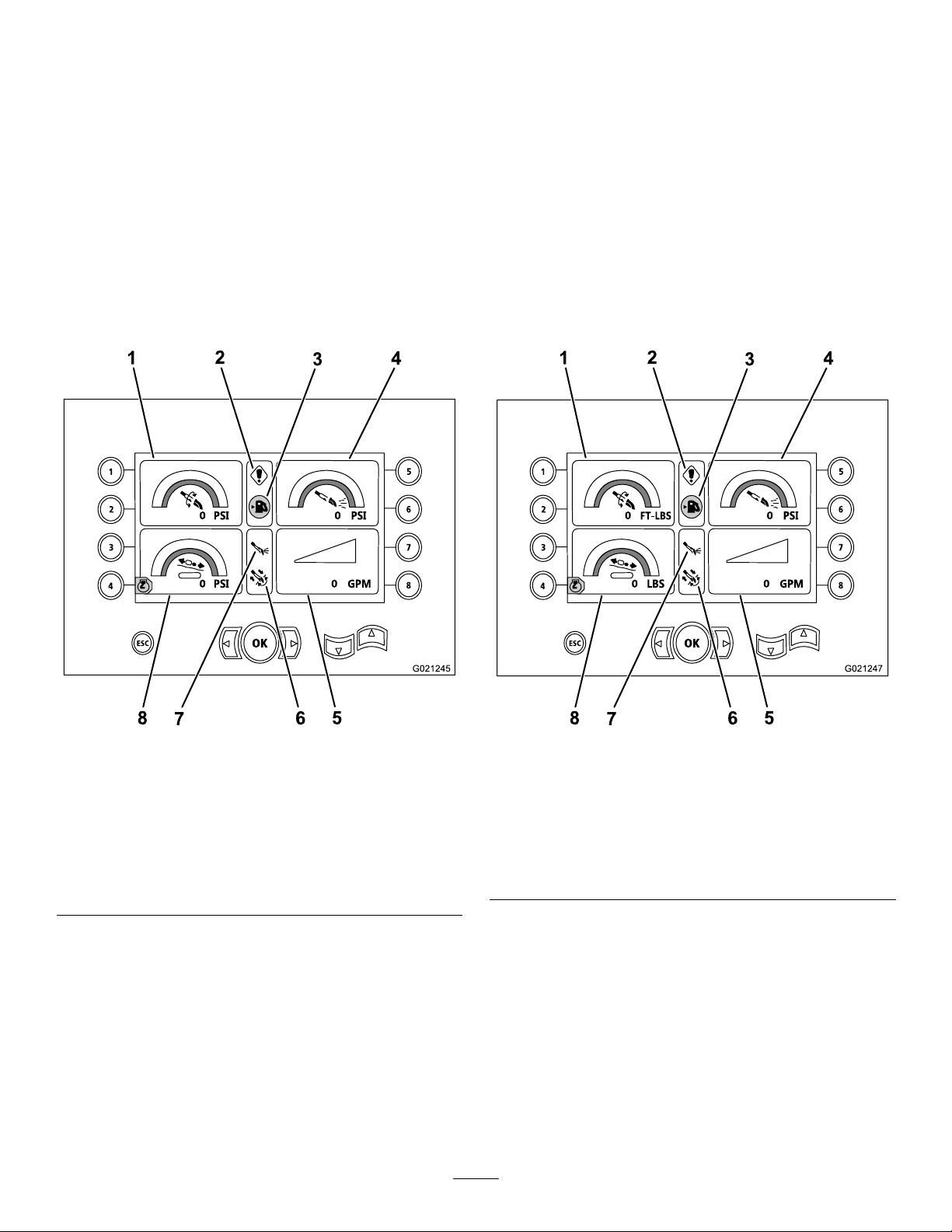
MainDrillFunctionsDisplayedinPressureScreen
MainDrillFunctionsDisplayedinTorqueScreen
Toaccessthisscreen,pressthedownarrowontheMain
OperatingScreen(page23).
Thisscreenprovidesmeasurementsonrotarypressureinpsi,
drilling-uidpressureinpsi,carriagepressureinpsi,and
drilling-uidowrateingpm(Figure16).
Therearealso4indicators(listedfromtoptobottominthe
middleofthescreen),whichindicatethefollowing:
•Drillingand/orengine-errorcodewarning(Figure16)
•Low-fuelwarning(Figure16)
•DrillinguidisintheOnposition(Figure16)
•AutodrillingisintheOnposition(Figure16)
Toaccessthisscreen,pressthedownarrowontheMainDrill
FunctionsDisplayedinPressureScreen(page24).
Thisscreenprovidesmeasurementsonrotarytorquein
ft-lbs,drilling-uidpressureinpsi,carriageforceinlbs,and
drilling-uidowrateingpm(Figure17).
Therearealso4indicators(listedfromtoptobottominthe
middleofthescreen),whichindicatethefollowing:
•Drillingand/orengine-errorcodewarning(Figure17)
•Low-fuelwarning(Figure17)
•DrillinguidisintheOnposition(Figure17)
•AutodrillingisintheOnposition(Figure17)
Figure16
MainDrillFunctionsDisplayedinPressureScreen
1.Rotarypressure(psi)5.Drilling-uidowrate
2.Drilling-faultindicator
3.Low-fuelindicator7.Drilling-uidindicator
4.Drilling-uidpressure(psi)8.Carriage-pressuregauge
(gpm)
6.Auto-drillingindicator
(psi)
Figure17
MainDrillFunctionsDisplayedinTorqueScreen
1.Rotarytorque(ft-lbs)5.Drilling-uidowrate
2.Drilling-faultindicator
3.Low-fuelindicator7.Drilling-uidindicator
4.Drilling-uidpressure(psi)8.Carriage-forcegauge(lb)
(gpm)
6.Auto-drillingindicator
24
Page 25
Drill-rotation-speedScreen
1
2
3
4
5
6
7
8
OK
ESC
6
12
18
24
30
n/min
x 100
1
2
3
4
g025794
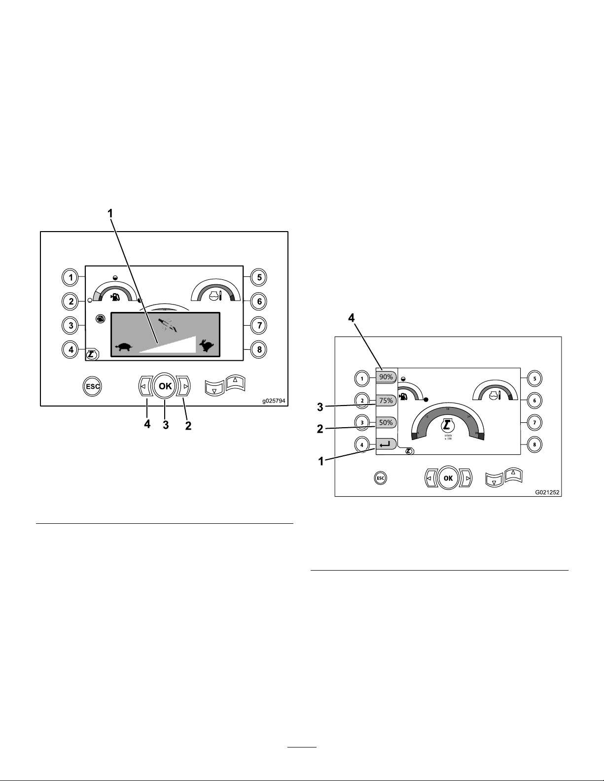
Horsepower-controlScreen
Toaccessthisscreen,simultaneouslypresstheOKbutton
andtheleftandrightarrowbuttonsontheMainOperating
Screen(page23).
Thisscreenallowstheusertoincreaseordecreasethe
rotationspeedofthedrill.
Tochangetherotationspeedofthedrill,performthe
following:
1.PresstheLeftarrowtodecreasethespeed,orpressthe
Rightarrowtoincreasethespeed(Figure18).
2.PresstheOKbuttontosetthedrill-rotationspeed
(Figure18).
Thehorsepowercontrolallowstheusertochangethe
engine-speed(rpm)settingthattheenginecandroopto
beforethehorsepower-controlsystemcanactivate.
Thehorsepowercontrolallowstheoperatortofunctionthe
unitatlowrpmlevels,sothattheenginecanstallunderheavy
loads.
Note:Forexample,atthe50%engine-speed(rpm)setting,
theenginecanstallunderheavyloads.
Afterselectingthehorsepowercontrol(Figure15),selectone
ofthefollowingoptions:
•Pressbuttonnumber1toactivate90%enginespeed
(rpm)asshowninFigure19.
•Pressbuttonnumber2toactivate75%enginespeed
(rpm)asshowninFigure19.
•Pressbuttonnumber3toactivate50%enginespeed
(rpm)asshowninFigure19.
•Pressbuttonnumber4toreturntothemain-operating
screen(Figure19).
1.Drill-rotationspeedmeter
2.Rightarrow(increase
speed)
Drill-rotation-speedScreen
Figure18
3.OKbutton(setsthe
4.Leftarrow(decrease
drill-rotationspeed)
speed)
Figure19
Horsepower-controlScreen
1.Returntopreviousscreen
2.50%enginespeed(rpm)4.90%enginespeed(rpm)
3.75%enginespeed(rpm)
25
Page 26
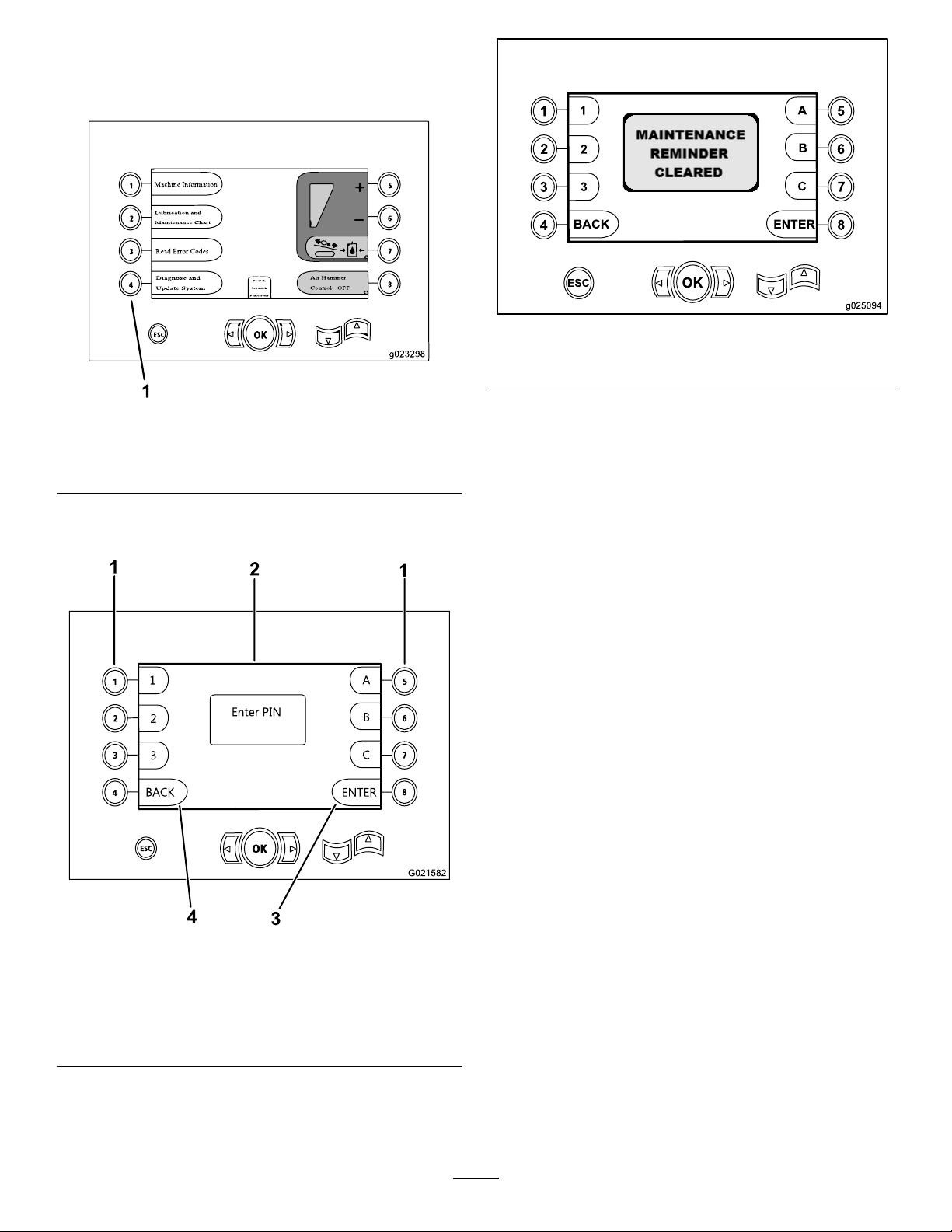
Clear-service-reminderScreen
1
2
3
4
5
6
7
8
OK
ESC
1
2
3
BACK
ENTER
A
B
C
Enter PIN
g025094
Toaccessthisscreen,pressbuttonnumber4asshownin
Figure20.
Figure20
Access-PINScreen
1.Buttonnumber4(diagnoseandupdatesystem)
Figure22
Maintenance-clearedScreen
Toclearaservicereminder,enterthe8-digitPIN(16527316)
intothisscreen(Figure21):
Figure21
Enter-PINScreen
1.Buttonsforcorresponding
PINnumbers
2.PINentryappearshere4.Returntotheprevious
Afterenteringthe8-digitPIN,thefollowingscreenwill
appearstatingthatthemaintenancereminderhasbeen
cleared(Figure22).
3.EnterPIN
screen
26
Page 27
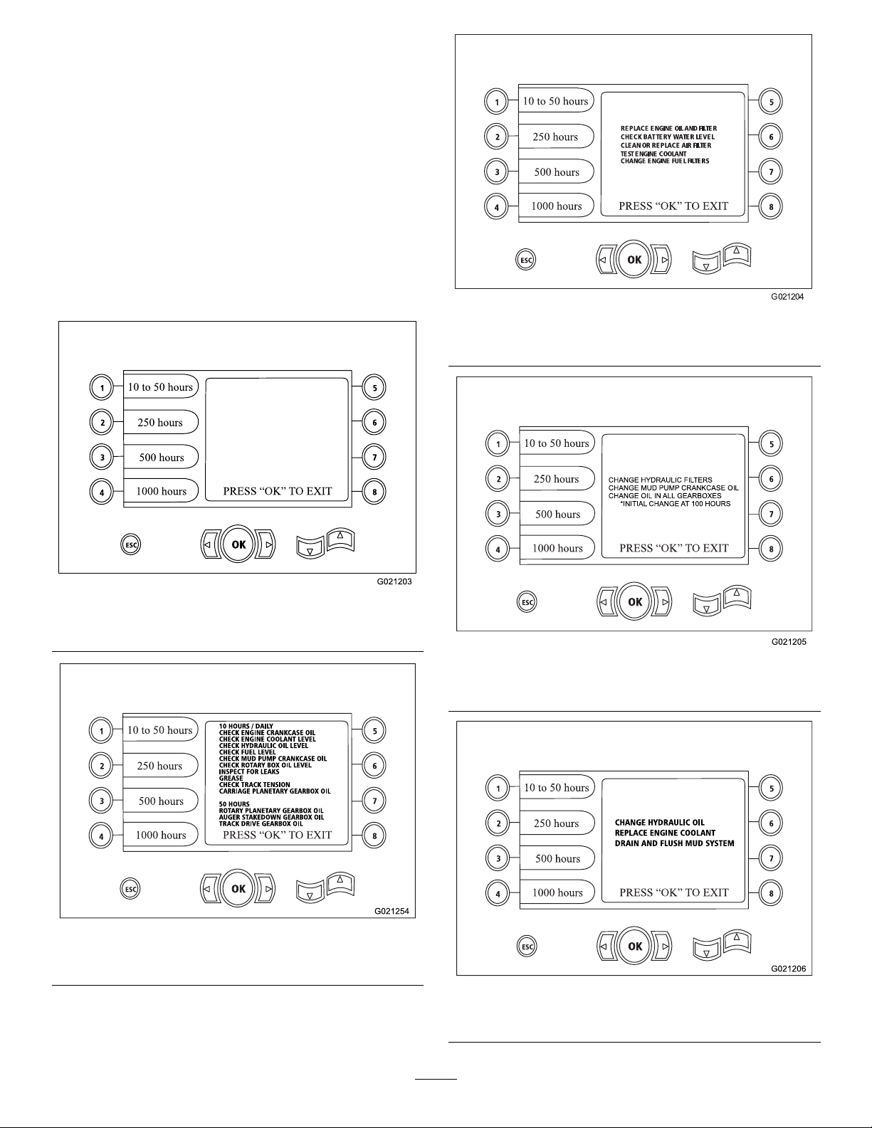
LubricationandMaintenanceScreens
Thesescreensprovidetheuserwithmaintenanceschedules
at10-hour,50-hour,250-hour,500-hour,and1,000-hour
increments.
Note:PresstheOKbuttontoexitthisscreen.
Pressthefollowingbuttontoattainthesubsequent
maintenanceschedule:
•Button1—10-hourand50-hourmaintenanceschedule
(Figure24)
•Button2—250-hourmaintenanceschedule(Figure25)
•Button3—500-hourmaintenanceschedule(Figure26)
•Button4—1,000-hourmaintenanceschedule(Figure27)
Figure23
MainMaintenanceScreen
Figure25
250-HourMaintenanceScreen
Figure26
500-HourMaintenanceScreen
Figure24
10-Hourand50-HourMaintenanceScreen
Figure27
1000-HourMaintenanceScreen
27
Page 28

ErrorCodesScreen
Thisscreendisplaysthenumberofdrillerrorsthathave
occurred.
Ifmorethan1drillerrorisshownonthescreen,pressbutton
6toseethenextdrillingerror(Figure28).
Note:Iftherearenodrillingerrors,presstheOKbuttonto
exitthisscreen(Figure28).
Thefollowinggureisanexampleofhowanerrorcode
appears.
Noticethatthetextbeforetheoccurrencecountentailswhat
theactualerroris.
Figure30
1.Totalnumberofdrilling
errors
Stored/ResetErrorCodesScreen
Figure28
2.Nextdrillingerror
1.Numberoferrorsand
numberofreseterrors
2.Nexterror
3.Reseterror
Carriage-pressureScreen
Whenthisscreenappears,thecarriage-pressureselectionis
intheOnposition(green)orOffposition(red),asshown
inFigure31.
1.Numberoferrorsand
numberofreseterrors
2.Reseterror
Figure29
3.Nexterror
1.Carriage-pressuregauge
2.Carriagepressureinthe
Off(red)position
3.Increasecarriagepressure
28
Figure31
4.Decreasecarriage
pressure
5.Air-hammercontrol
6.Switchjoystickfunctions
Page 29
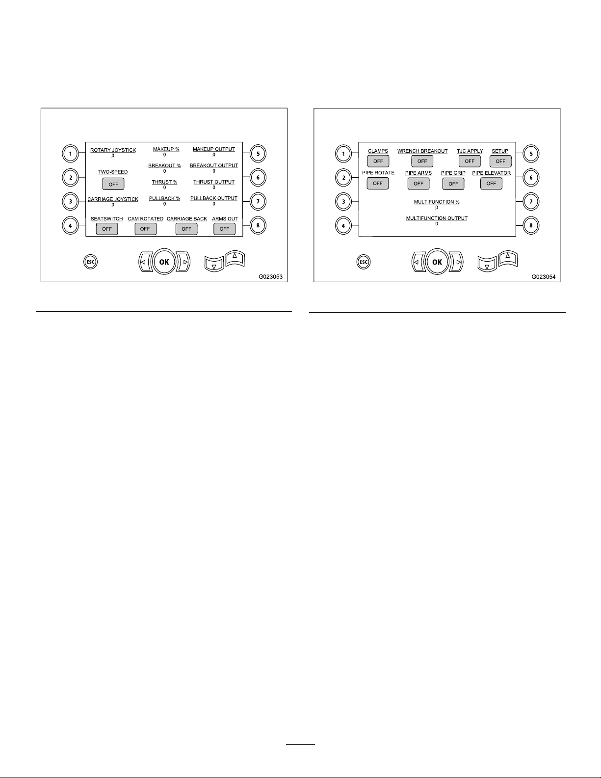
RotaryandCarriage-serviceScreen
Auxiliary-activationsScreen
FromtheMainOperatingScreen(page23),pressbutton
numbers1and5simultaneouslytoaccessthisscreen.
Therotaryandcarriageservicescreen(Figure32)provides
thefollowinginformation:
Figure32
•Rotaryandcarriagejoystickoutput
•Makeuppercentageandoutput
•Breakoutpercentageandoutput
•Thrustpercentageandoutput
PressthedownarrowontheRotaryandCarriage-service
Screen(page29)toaccessthisscreen.
Theauxiliary-activationsscreen(Figure33)providesthe
followinginformation:
Figure33
•OnandOffindicatorsforclamps,wrenchbreakout,TJC
applicator,setup,piperotation,pipearms,pipegrip,and
pipeelevator
•Multifunctionpercentageandoutput
•Pullbackpercentageandoutput
•OnandOffindicatorsfortwo-speed,seatsswitch,cam
rotation,carriageback,andarmsout
29
Page 30
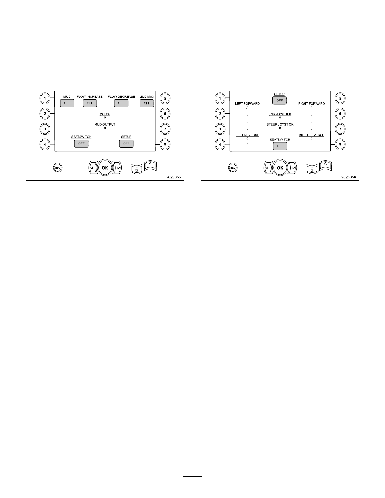
Drilling-uid-informationScreen
Track-drive-informationScreen
PressthedownarrowontheAuxiliary-activations
Screen(page29)toaccessthisscreen.
Thedrilling-uid-informationscreen(Figure34)providesthe
followinginformation:
Figure34
•OnandOffindicatorsfordrillinguid,owincrease,
owincrease,andmudmax
PressthedownarrowontheDrilling-uid-information
Screen(page30)toaccessthisscreen.
Thetrack-drive-informationscreen(Figure35)providesthe
followinginformation:
Figure35
•Outputforleftforward,leftreverse,rightforward,and
rightreversemovementsofthetrackdrive
•OnandOffindicatorsforseatswitchandsetup
•Drillinguidpercentageandoutput
•Front-Neutral-Reverse(FNR)andsteerjoystickoutput
•OnandOffindicatorsforsetupandseatswitch
30
Page 31
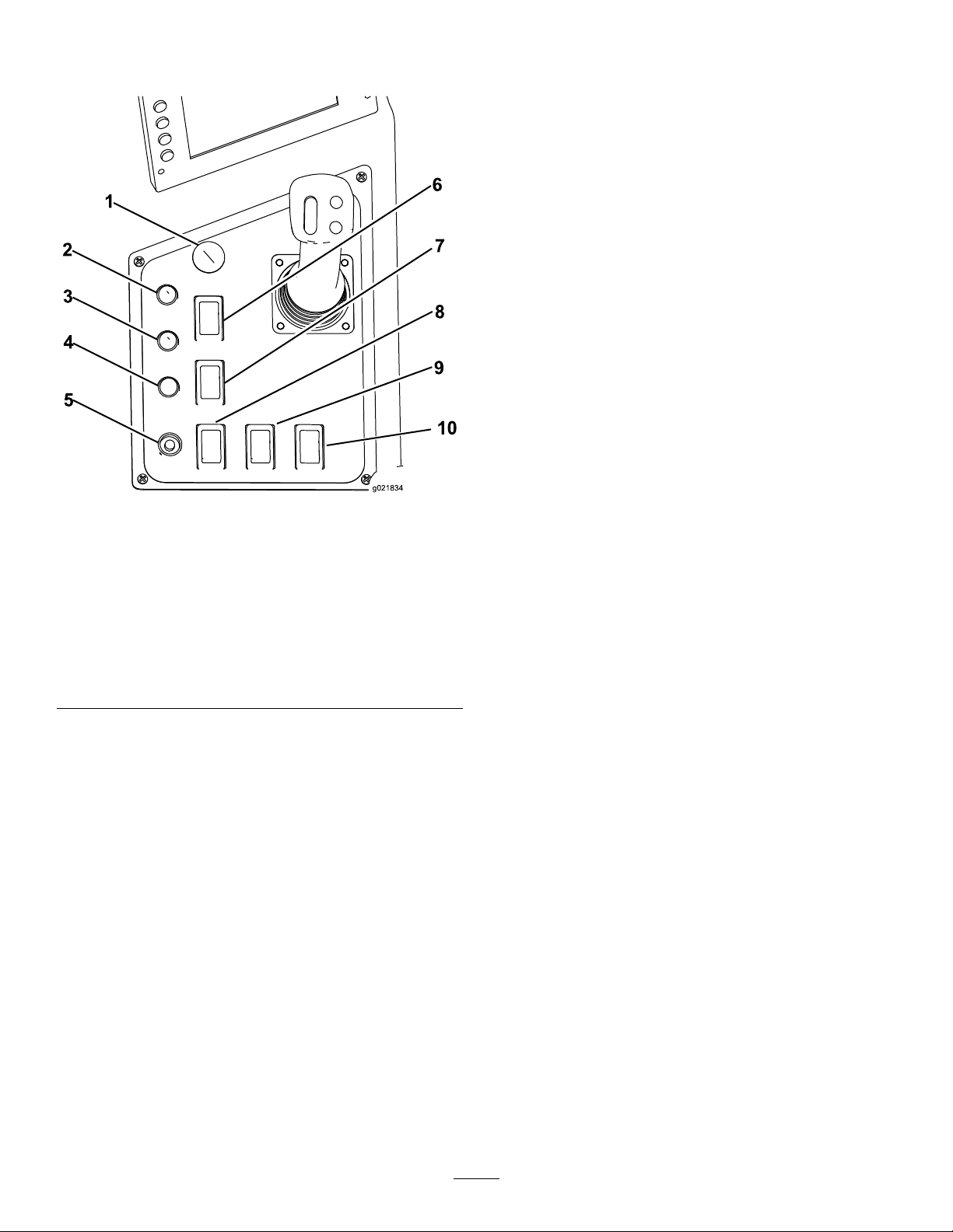
ControlPanel
g021834
1
2
3
4
5
6
7
8
9
10
Engine-StartButton
Pressthisbutton(Figure36)tostarttheengine.Thekey
switchontherear,controlpanelmustbeintheONposition.
Engine-StopButton
Pressthisbutton(Figure36)toimmediatelystoptheengine
andalldrillingoperations.Youmustpullthisbuttonout
beforeyoucanstarttheengineagain.
Ground-Strike-ResetSwitch
Pressthisswitch(Figure36)toresettheZap-Alertsystem
afteragroundstrikehasoccurredandbeenxed;referto
DeployingtheZap-AlertSystem(page62).
Drive/DrillSwitch
Pressthetopofthisswitch(Figure36)toenablethedriveand
setupcontrolsorthebottomtoenabledrillandpipe-loader
functions.
LightsSwitch
Figure36
1.Engine-stopbutton
2.Exit-sidelockout—reset
light
3.Exit-side
lockout—drill-enabled
light
4.Receiver-battery-status
light
5.Engine-startbutton10.Engine-speedswitch
Exit-SideLockout—ResetLight
6.Ground-strike-resetswitch
7.Exit-side-lockout—reset
switch
8.Drive/drillswitch
9.Lightsswitch
Thislight(Figure36)illuminatesyellowwhentheexit-side
lockoutfunctionisturnedoffonexit-side-lockouttransmitter,
indicatingthatyoumayresetthesystem.
Exit-SideLockout—Drill-enabledLight
Thislight(Figure36)illuminatesgreenwhenthe
exit-side-lockoutfeaturehasbeenturnedoffandresetand
themachineisreadytodrill.
Exit-SideLockout—ResetSwitch
Pressthetopofthisswitch(Figure36)toturnthemachine
lightsonorthebottomtoturnthemoff.
Engine-SpeedSwitch
•Pressandholdthetopofthisswitchtoincreasethe
enginespeed.
•Pressandholdthebottomofthisswitchtodecreasethe
enginespeed.
•Releasetheswitchtomaintainthecurrentenginespeed.
Pressthisswitch(Figure36)toenabledrillingoperationwhen
theresetlightilluminates.
Transmitter-Battery—StatusLight
Thislight(Figure36)illuminatesredwhenthebatteryon
theexit-side-lockouttransmitteristoolowtotransmit.Stop
drillingoperationsandxtheproblemwiththetransmitter
beforecontinuing.
31
Page 32
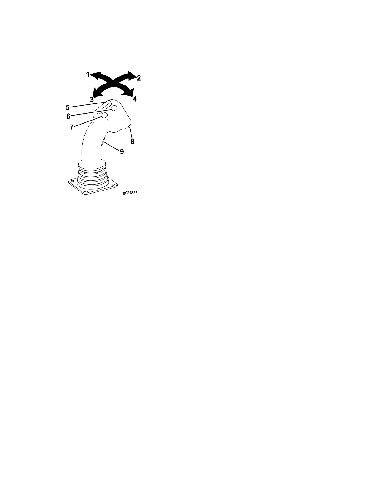
LeftJoystick—ModeI
g021833
5
6
7
8
9
4
2
3
1
FrontButton
Note:Thejoystickcontrolsvarydependingonthecontrol
modeyouselectwhenpoweringupthemachine.There
are2controlmodes:ModeIandModeII;refertothe
Control-SelectScreenintheSoftwareGuideforinformation
onsettingthecontrolmode.
Figure37
1.Joystick—moveleft
2.Joystick—moveforward
3.Joystick—moverearward8.Lowerbutton
4.Joystick—moveright9.Trigger
5.Toggleswitch
6.Frontbutton
7.Rearbutton
•Lefttriggerpressed—pressthisbuttontoresumethe
previouslysetauto-drillspeed.Pressandholdthisbutton
toincreasetheauto-drillspeed.
•Lefttriggerreleased—pressthisbuttontoclosethepipe
gripper.
RearButton
•Lefttriggerpressed—pressthisbuttontosettheauto
drillspeed.Pressandholdthisbuttontodecreasethe
auto-drillspeed.
•Lefttriggerreleased—pressthisbuttontoopenthepipe
gripper.
LowerButton
Intheeventofasensorfailure,usethisbuttontooverridethe
pipecampresetsandmanuallymovethecam.Onlyoperate
inthismodeifabsolutelynecessary;youcoulddamagethe
pipecamorpipesifyoudonotalignthemcorrectly.Ifthe
sensorfails,contactyourAuthorizedToroDealerforrepair.
Joystick—Forward
•Lefttriggerpressed—closesthelowerwrench.
•Lefttriggerreleased—retractsthepipegrippertoward
thepipeholder.
Joystick—Rearward
•Lefttriggerpressed—opensthelowerwrench.
Trigger
Thetriggerchangestheotherjoystickcontrolsfrompipe
loadercontrolstowrenchoperationcontrols.
•Pressthetriggertoenablethewrenchcontrols.
•Releasethetriggertoenablethepipeloadercontrols.
ToggleSwitch
•Lefttriggerpressed—rocktheswitchforwardto
rotatetheupperwrenchclockwisetoloosenajoint;
rocktheswitchrearwardtorotatetheupperwrench
counterclockwisetotightenajoint.
•Lefttriggerreleased—rocktheswitchforwardtorotate
thepipecamouttowardsthepipeloader;rocktheswitch
rearwardtorotatethepipecamtowardsthedrillframe.
•Lefttriggerreleased—extendsthepipegrippertoward
thedrillframe.
Joystick—Left
•Lefttriggerpressed—openstheupperwrench.
•Lefttriggerreleased—lowersthepipeelevator.
Joystick—Right
•Lefttriggerpressed—closestheupperwrench.
•Lefttriggerreleased—raisesthepipeelevator.
32
Page 33
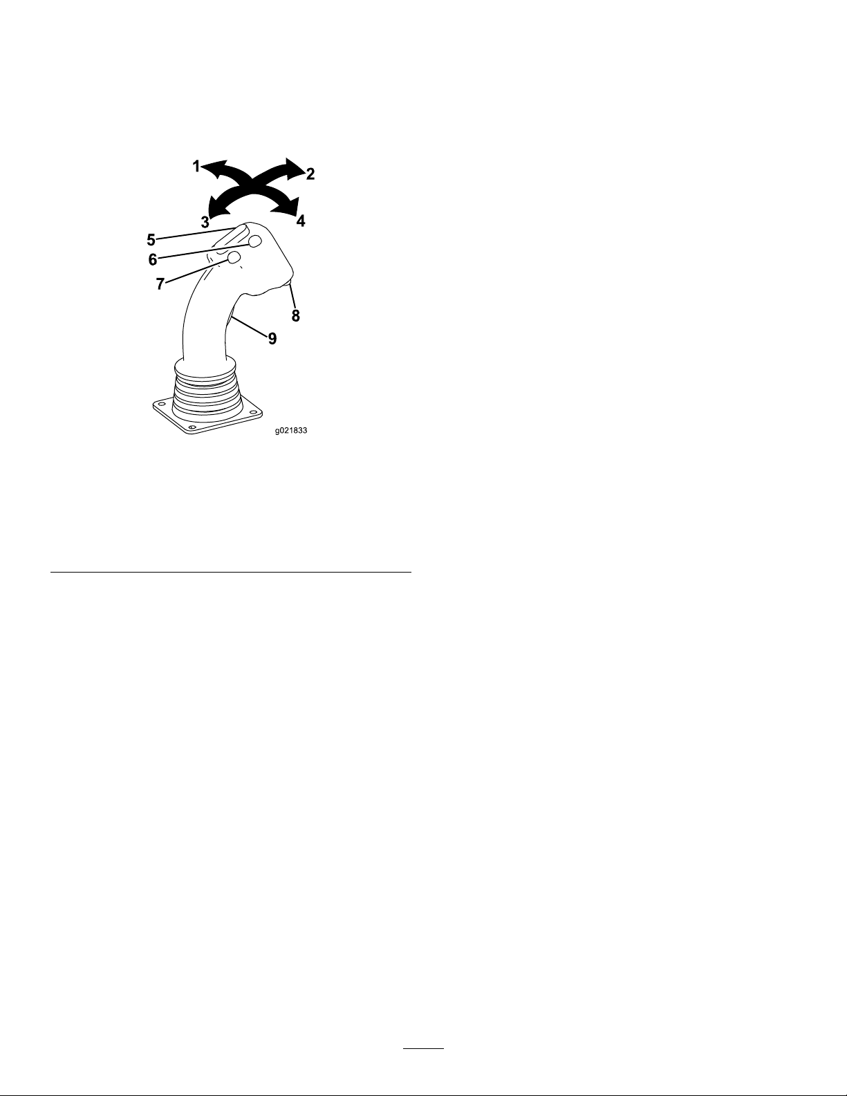
LeftJoystick—ModeII
g021833
5
6
7
8
9
4
2
3
1
FrontButton
Note:Thejoystickcontrolsvarydependingonthecontrol
modeyouselectwhenpoweringupthemachine.There
are2controlmodes:ModeIandModeII;refertothe
Control-SelectScreenintheSoftwareGuideforinformation
onsettingthecontrolmode.
Figure38
1.Joystick—moveleft
2.Joystick—moveforward
3.Joystick—moverearward8.Lowerbutton
4.Joystick—moveright9.Trigger
5.Toggleswitch
6.Frontbutton
7.Rearbutton
•Lefttriggerpressed—pressthisbuttontoresumethe
previouslysetauto-drillspeed.Pressandholdthisbutton
toincreasetheauto-drillspeed.
•Lefttriggerreleased—pressthisbuttontoclosethepipe
gripper.
RearButton
•Lefttriggerpressed—pressthisbuttontosettheauto
drillspeed.Pressandholdthisbuttontodecreasethe
auto-drillspeed.
•Lefttriggerreleased—pressthisbuttontoopenthepipe
gripper.
LowerButton
Intheeventofasensorfailure,usethisbuttontooverridethe
pipecampresetsandmanuallymovethecam.Onlyoperate
inthismodeifabsolutelynecessary;youcoulddamagethe
pipecamorpipesifyoudonotalignthemcorrectly.Ifthe
sensorfails,contactyourAuthorizedToroDealerforrepair.
Joystick—Forward
Pushthejoystickforwardtospinthedrillspindle
counterclockwise.
Joystick—Rearward
Pullthejoystickrearwardtospinthedrillspindleclockwise.
Trigger
Joystick—Left
•Lefttriggerpressed—openstheupperwrench.
Thetriggerchangestheotherjoystickcontrolsfrompipe
loadercontrolstowrenchoperationcontrols.
•Lefttriggerreleased—extendsthepipegrippertoward
thedrillframe.
•Pressthetriggertoenablethewrenchcontrols.
•Releasethetriggertoenablethepipeloadercontrols.
Joystick—Right
•Lefttriggerpressed—closestheupperwrench.
ToggleSwitch
•Lefttriggerreleased—retractsthepipegrippertoward
•Lefttriggerpressed—rocktheswitchforwardto
rotatetheupperwrenchclockwisetoloosenajoint;
rocktheswitchrearwardtorotatetheupperwrench
counterclockwisetotightenajoint.
•Lefttriggerreleased—rocktheswitchforwardtorotate
thepipecamouttowardsthepipeloader;rocktheswitch
rearwardtorotatethepipecamtowardsthedrillframe.
thepipeholder.
33
Page 34
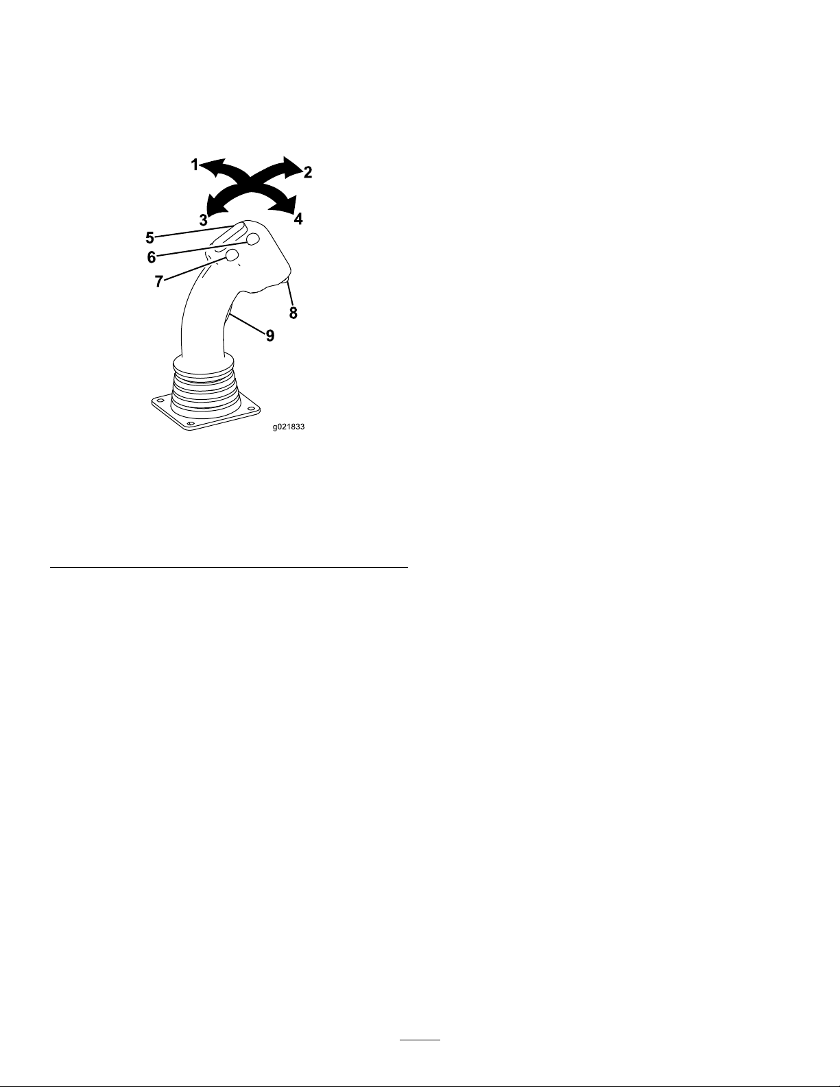
RightJoystick—ModeI
g021833
5
6
7
8
9
4
2
3
1
LowerButton
Note:Thejoystickcontrolsvarydependingonthecontrol
modeyouselectwhenpoweringupthemachine.There
are2controlmodes:ModeIandModeII;refertothe
Control-SelectScreenintheSoftwareGuideforinformation
onsettingthecontrolmode.
Figure39
1.Joystick—moveleft
2.Joystick—moveforward
3.Joystick—moverearward8.Lowerbutton
4.Joystick—moveright9.Trigger
5.Toggleswitch
6.Frontbutton
7.Rearbutton
Pressthisbuttontoturnthedrilling-uidpumponoroff.
Trigger
Pressandholdthetriggertomovethedrillcarriageathigh
speedupordownthedrillframe.
Joystick—Forward
Pushthejoystickforwardtothrustthedrillcarriageforward.
Joystick—Rearward
Pullthejoystickrearwardtopullthedrillcarriagerearward.
Joystick—Left
Pushthejoysticklefttospinthedrillspindleclockwise.
Joystick—Right
Pushthejoystickrighttospinthedrillspindle
counterclockwise.
ToggleSwitch
Rocktheswitchforwardtoincreasetherateofowofthe
drillinguid;rocktheswitchrearwardtodecreasetherate
ofowofthedrillinguid.
Note:Beforeusingthisfeatureyoumustrstturnon
thedrilling-uidpumpusingthelowerbuttonontheright
joystick.
FrontButton
Pressthisbuttontoapplytread-jointcompound.
RearButton
Pressandholdthisbuttonformaximumdrillinguid
pressure;usethistoquicklyllthepipewithdrillinguid
afteraddingorremovingapipe.Releasethebuttontostop
theoworreturntothepreviouslysetowrate.
34
Page 35
RightJoystick—ModeII
g021833
5
6
7
8
9
4
2
3
1
LowerButton
Note:Thejoystickcontrolsvarydependingonthecontrol
modeyouselectwhenpoweringupthemachine.Thereare2
controlmodes:ModeIandModeII;refertoControl-Select
ScreenintheSoftwareGuideforinformationonsettingthe
controlmode.
Figure40
1.Joystick—moveleft
2.Joystick—moveforward
3.Joystick—moverearward8.Lowerbutton
4.Joystick—moveright9.Trigger
5.Toggleswitch
6.Frontbutton
7.Rearbutton
Pressthisbuttontoturnthedrilling-uidpumponoroff.
Trigger
Pressandholdthetriggertomovethedrillcarriageathigh
speedupordownthedrillframe.
Joystick—Forward
Pushthejoystickforwardtothrustthedrillcarriageforward.
Joystick—Rearward
Pullthejoystickrearwardtopullthedrillcarriagerearward.
Joystick—Left
•Lefttriggerpressed—opensthelowerwrench.
•Lefttriggerreleased—raisesthepipeelevator.
Joystick—Right
•Lefttriggerpressed—closesthelowerwrench.
•Lefttriggerreleased—lowersthepipeelevator.
ToggleSwitch
Rocktheswitchforwardtoincreasetherateofowofthe
drillinguid;rocktheswitchrearwardtodecreasetherate
ofowofthedrillinguid.
Note:Beforeusingthisfeatureyoumustrstturnon
thedrilling-uidpumpusingthelowerbuttonontheright
joystick.
FrontButton
Pressthisbuttontoapplytread-jointcompound.
RearButton
Pressandholdthisbuttonformaximumdrillinguid
pressure;usethistoquicklyllthepipewithdrillinguid
afteraddingorremovingapipe.Releasethebuttontostop
theoworreturntothepreviouslysetowrate.
35
Page 36
Exit-Side-LockoutSystem(Standard
g021837
1
2
3
4
5
1
2
3
G0221 15
Range)
Theexit-side-lockoutsystemprovidestheindividualsworking
aroundthemachinewithameanstodisablethedrillpipe
fromrotatingandthrusting.
Formoreinformationandinstructions,refertotheOperator’s
ManualfortheExit-side-lockoutsystem.
Exit-Side-LockoutSystem(Long
Range)
Theexit-side-lockoutsystemprovidestheindividualsworking
aroundthemachinewithameanstodisablethedrillpipe
fromrotatingandthrusting.
Formoreinformationandinstructions,refertotheOperator’s
ManualfortheExit-side-lockoutsystem.
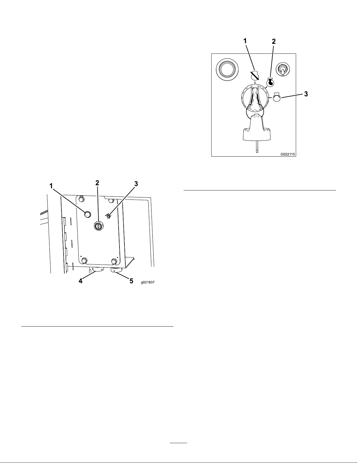
Engine,KeySwitch
Thekeyswitchhas3positionsasfollows(Figure42):
RearControlPanel
Figure41
1.Engine-heatinglight4.Drill-pendantreceptacle
2.Engine,keyswitch5.Drive-pendantreceptacle
3.Fluid-pumpswitch
Figure42
1.Engine-offposition
2.Engine-runposition
3.Engine-startposition
•Engine-offposition—turnthekeytothispositionto
stoptheengine.Theenginecannotbestartedfromthe
operatorplatformwhenthekeyisinthisposition.
•Engine-runposition—turnthekeytothispositionafter
startingtheengine.Turningthekeytothisposition
alsoenablestheenginestartbuttonfromtheoperator
platform.
•Engine-startposition—turnthekeytothispositionto
starttheengine.ReleasethekeytotheRUNpositiononce
theenginehasstarted.
Fluid-PumpSwitch
Usethisswitchtoturnontheuidpumptousethespraygun
whencleaningthemachine.
Drill-PendantReceptacle
Engine-HeatingLight
Whentheengineiscold,theheaterwarmstheintakeairto
enableeasierstarting.Thislightilluminateswhiletheheateris
on.Waituntilthislightturnsoffbeforestartingtheengine.
Plugthedrillpendantintothisreceptacletoattachittothe
machine(Figure41).
Drive-PendantReceptacle
Plugthedrivependantintothisreceptacletoattachittothe
machine(Figure41).
36
Page 37
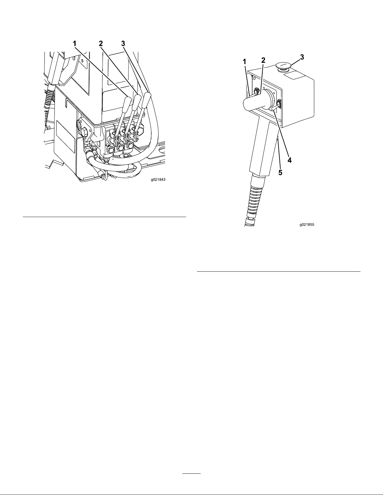
DrillFrameandStabilizerControls
g021843
1 2 3
g021855
1
2
4
3
5
DrivePendant
RefertoFigure41forlocation.
Figure43
1.Drill-frametiltlever
2.Left-stabilizerlever
StabilizerLevers
Usethestabilizerleverstoraiseandlowerthestabilizers.
Note:TheDRIVE/DRILLswitchontheoperatorpanelmust
beswitchedtotheDRIVEpositionforthisfunctiontowork.
Drill-FrameTiltLever
3.Right-stabilizerlever
Figure44
1.Engine-speedswitch4.Drive-speedswitch
2.Drive-directionjoystick
3.Engine-stopbutton
Engine-StopButton
5.Operator-presenceswitch
Usethedrill-frametiltlevertotiltthedrillframetoplace
thestake-downplateonthegroundortoreturntheframe
tothetravelposition.
Pressthisbuttontoimmediatelystoptheengineandall
movement/drillingoperations.Youmustpullthisbuttonout
beforeyoucanstarttheengineagain.
Note:TheDRIVE/DRILLswitchontheoperatorpanelmust
beswitchedtotheDRIVEpositionforthisfunctiontowork.
Engine-SpeedSwitch
•Pressandholdthetopofthisswitchtoincreasethe
enginespeed.
•Pressandholdthebottomofthisswitchtodecreasethe
enginespeed.
•Releasetheswitchtomaintainthecurrentenginespeed.
Drive-DirectionJoystick
Usethejoysticktocontrolthedirectionofthemachine.The
machinewilltravelinthedirectionyoumovethejoystick.
37
Page 38
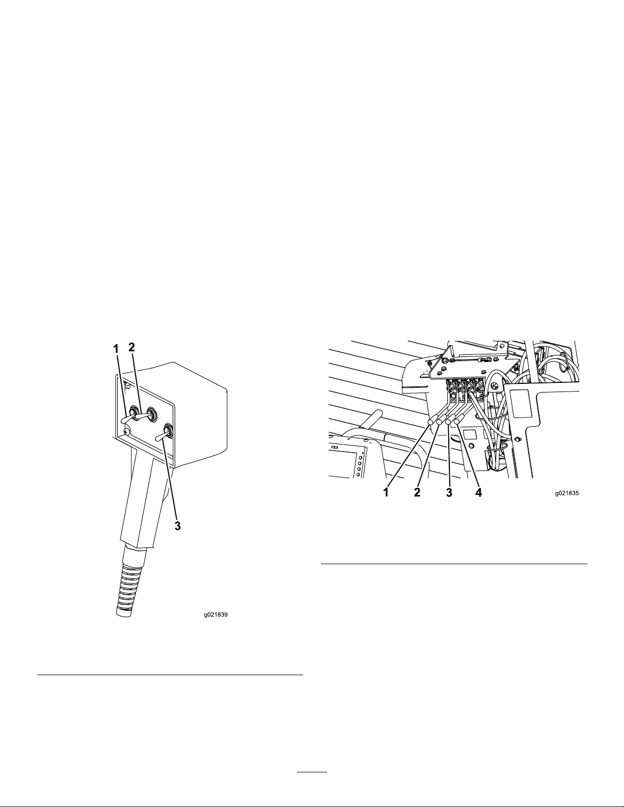
Drive-SpeedSwitch
g021839
1
2
3
g021835
1
2
3 4
LeftSwitch
Theswitchsetsthespeedatwhichthemachinewilltravel.
Movetheswitchupforhighspeedordownforlowspeed.
Operator-PresenceSwitch
Pressandholdthisbuttontoenabletheothercontrolsonthe
drivependant.Themachinewillstopmovingifyourelease
thisbutton.
DrillPendant
Thedrillpendant(alsoreferredtoasthelife-jacket
pendant)isdesignedtoallowyourudimentarycontrol
overonlythedrillingfeatureswhenconnectedtothefront
receptacle,shouldtheoperatorplatformcontrolsbecome
non-responsive.Youcanalsoplugthispendantintotherear
drill-pendantreceptacleintheeventthatthedrivependant
malfunctionstoobtainbasicmovementfunctionsatslow
speed.
Onlythedrivefunctionscanbeoperatedfromtherear
drill-pendantreceptacle.
RefertoFigure41forlocation.
•Whenconnectedtothedrill-pendantreceptacle,move
thisswitchuptomovethedrillcarriageforwardordown
tomovethedrillcarriagerearward.
•Whenconnectedtothedrive-pendantreceptacle,move
thisswitchuptomovethelefttrackforwardordownto
movethelefttrackrearward.
CenterSwitch
Movethisswitchtothelefttoenablethepipeloaderand
wrenchoperation;movetheswitchtothecentertoturnoff
thedrillinguid.
RightSwitch
•Whenconnectedtothefrontdrill-pendantreceptacle,
movethisswitchuptorotatethedrillspindleclockwise
ordowntorotatethedrillspindlecounterclockwise.
•Whenconnectedtothereardrill-pendantreceptacle,
movethisswitchuptomovetherighttrackforwardor
downtomovetherighttrackrearward.
Stake-DownLevers
Figure46
1.Left-stake-raise/lower
lever
2.Left-stake-spinlever
Stake-Raise/LowerLevers
3.Right-stake-raise/lower
lever
4.Right-stake-spinlever
Pushdownontheseleverstolowerthestakesintotheground.
Pullupontheseleverstoraisethestakesoutoftheground.
Note:TheDRIVE/DRILLswitchontheoperatorpanelmust
beswitchedtotheDRIVEpositionforthisfunctiontowork.
Stake-SpinLevers
1.Leftswitch
2.Centerswitch
Figure45
3.Rightswitch
Pushdownontheseleverstospinthestakesclockwise.Pull
upontheseleverstospinthestakescounterclockwise.
Note:TheDRIVE/DRILLswitchontheoperatorpanelmust
beswitchedtotheDRIVEpositionforthisfunctiontowork.
38
Page 39
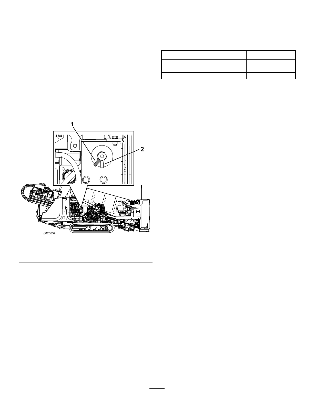
Battery-DisconnectSwitch
Specications
OpenthefronthoodtoaccesstheBATTERY-DISCONNECT
switch;refertoOpeningtheFrontHood(page72).
TheBATTERY-DISCONNECTswitchislocatedtotherightof
theengine;itisusedtoelectricallydisconnectthebattery
fromthemachine.
TurntheBATTERY-DISCONNECTswitchtotheONorOFF
positiontoperformthefollowing:
•Toenergizethemachineelectrically,rotatethe
BATTERY-DISCONNECTswitchclockwisetotheON
position(Figure47).
•Tode-energizethemachineelectrically,rotatethe
BATTERY-DISCONNECTswitchcounterclockwisetothe
OFFposition(Figure47).
Note:Specicationsanddesignaresubjecttochange
withoutnotice.
Machine
Width
Length
Height
Weight
131cm(51.5inches)
525cm(207inches)
188cm(74inches)
4,765kg(10,500lbs)
Attachments/Accessories
AselectionofToroapprovedattachmentsandaccessoriesis
availableforusewiththemachinetoenhanceandexpand
itscapabilities.ContactyourAuthorizedServiceDealeror
Distributororgotowww .Toro.comforalistofallapproved
attachmentsandaccessories.
Important:UseonlyToroapprovedattachments.
Otherattachmentsmaycreateanunsafeoperating
environmentordamagethetractionunit.
1.Battery-disconnectswitch
(Onposition)
Figure47
2.Battery-disconnectswitch
(Offposition)
39
Page 40

Operation
Note:Determinetheleftandrightsidesofthemachine
fromthenormaloperatingposition.
RefertoPreparingtheJobSiteandtheMachine(page
52)forinstructionsonpreparingthejobsiteandthe
machine.
4.Drillthebore.
Youdrilltheboreinthreestages:
UnderstandingHorizontal
DirectionalDrilling
Horizontaldirectionaldrillingisaprocessusedfordrillinga
horizontalborethroughthesoilandunderobstructionssuch
asroads,buildings,bodiesofwater,etc.Onceyoudrillthe
bore,youpullbacktheutilitylinesorpipesthroughthebore
andconnectthemasneeded.Becauseitdoesnotrequire
verymuchdisturbanceofthesurface,installationofutilities
usingdirectionaldrillingpreservestheenvironmentandsaves
bothtimeandmoneyovertraditionalinstallationmethods
suchastrenching.
Wheninstallingcablingorpipeusingadirectionaldrill,you
completethefollowingsteps:
1.Gathersiteinformation.
Beforeoperatinginanareawithhigh-voltagelinesor
cables,contacta“One-CallSystemDirectory”service.
IntheUSA,call811oryourlocalutilitycompany.If
youdonotknowyourlocalutilitycompany’ sphone
number,callthenationalnumber(USAandCanada
only)at1-888-258-0808.Also,contactanyutility
companiesthatarenotparticipantsofthe“One-Call
SystemDirectory”service.PleaserefertoDrilling
NearUtilityLines(page6)formoreinformation.
Beforefullyplanningthebore,youmustgather
informationaboutthejobsitesuchasthelocationof
otherutilities,obstaclesatthesite,andwhatregulations
andpermitsyouwillneedtocompletethejob;referto
GatheringSiteInformation(page41).
2.Planthebore.
Beforeyoucandrill,youmustrstplantheborepath
basedontheinformationyougathered.Referto
PlanningtheBorePath(page43).
3.Preparethejobsiteandthemachine.
Beforedrilling,youpreparethejobsitewithanentry
point,depth-gaugehole(optional),andanexithole.
Youalsoneedtodrivetheunittothesite,setitupfor
drilling,andconnectittoadrilling-uidmixer.
A.Entry
Intheentryphaseofthebore,youpushthedrill
bitandheadintothegroundatanangleofupto
16degrees.Afterpushinginoneormorepipes,
youbegindrillingdownandforwarduntilyou
reachthedesireddepthordepth-gaugehole(if
used).
B.HorizontalReach
Afterreachingthedesireddepth,youpushthe
bitforward,steeringthebittoahorizontaldepth.
Thedrillbitemitsaradiosignalfromthesonde
housing,whichallowsacrewmemberonthe
surfacetotrackthelocationanddepthofthehead
usingthesondereceiverasyoudrillandsteerit
alongaplannedroute.
C.Exit
Onceyouhaveattainedtheplannedhorizontal
reach,yousteertheheadupatananglesimilar
toyourentryanglebringingthebitintotheexit
holeortrench.
RefertoDrillingtheBore(page63).
5.Backreamtheboreandpullbackthecablingor
pipe.
Afterenteringtheexithole,theendcrewdetachesthe
drillbitandsondehousingfromthedrillpipe.Inits
place,theyattachareamingbitandtheendofthecable
orpipetobepulledthroughthebore.Thereaming
bitisdesignedtoenlargetheboreasyoupullitback.
Asbefore,youpumpdrillinguidthroughthepipe
tothereamingbitasyoupullthecableorpipeback
throughtheboretolubricatethereamerandallow
thecableorpipetoslideeasilythroughthebore.You
continuepullingthepipebackuntilthereamerreaches
thedepth-gaugeholeorexitsattheentrypoint.There
youremovethereamerandproductfromthedrillpipe,
pullingthepipetherestofthewaybacktothemachine.
RefertoBackreamingandPullback(page66)for
instructionsonbackreamingandpullingcableorpipe.
Note:Whendrilling,youconnectthemachinetoa
drilling-uidmixerthatmixeswaterwithbentonite
clayandotheringredients.Themachinepumpsthis
mixture,referredtoasdrillinguidor“Mud”,through
thedrillpipeandoutthedrillbit.Thedrillinguid
lubricatesthebit,helpstoholdtheboreopenwhile
drilling,andmixeswiththespoils,ushingthemout
oftheborethroughtheentrypoint.
6.Finishtheboreandleavethejobsite.
Aftercompletingtheoperation,youneedtodisconnect
andcleanthemachineandloaditonthetrailer;referto
CleaningwiththeSpray-hoseAttachment(page102).
40
Page 41

GatheringSiteInformation
PlanningtheInitialRoute
Beforeyoucanbeginboring,youneedtoplantherouteyou
willboreandprepareasfollows:
•Createabasicplanforthebore,mappingoutthe
proposedroute.
–Noteanyobstacleswhichmayaffecttheboresuchas
largetrees,bodiesofwater,buildings,etc.
–Plantherouteoftheboretoavoidasmanyobstacles
aspossible.
–Determinethedepthofanybodiesofwatertobe
crossedtoensurethatyoucangetdeepenoughunder
them.
•Determinethedepthyouneedtoinstallthematerialat
andtheminimumbendradiusbothofthedrillpipeand
ofthematerialbeinginstalled.Thiswillseriouslyaffect
howlongtheboreneedstobeandatwhatangleyoucan
beginandend;refertoPlanningtheBorePath(page43).
•Havetheareaoftheboremarkedforutilitylines(inthe
UScall811).Ensurethatalllinesaremarkedonyour
blueprints/boreplanaswell.
•Contactthelocalauthoritiestoarrangeforanypermits
andtrafccontrolthatyouwillneedtoconductthejob.
InspectingtheProposedJobSite
Physicallyinspectthesiteasfollows:
•Notetheterrain,slopes,valleys,hills,andanyfeatures
notplannedforpreviously.
Determinethedegreeofslopeatboththeproposedentry
pointandexitpoint.
•Determinewhatthesoiltypesareintheareaand,if
possible,whattheyareatthedepthyouwillbeboring.
Youmayneedtodigtestholesatintervalsalongthebore
pathtofullydeterminethis.
•Walktheareaoftheborelookingforanypossible
unmarkedobstructions.Lookformanholes,pedestals,
oldfoundations,etc.
•Identifyallhazardsofwhichyouwillbepassingwithin
3m(10ft).
DANGER
Contactingundergroundhazardswiththe
machinewhiledrillingorreamingcancause
explosion,electrocution,breathingproblems,
severetrauma,anddeathtoyouorbystanders.
–Ensurethatallpersonnelatthejobsitewear
personalprotectiveequipmentincluding
ahardhat,eyeprotection,andhearing
protection.
–Keepbystandersandspectatorsawayfrom
thejobsite,includingthecompletebore
path.
–Locateandexposeallelectricandgaslines
thatyouwillbecrossingbycarefulhand
digging.
–EnsurethatyouusetheZap-Alertsystem
wheneveroperatingthemachine.
Commonhazardsincludethefollowing:
–Gaslines
DANGER
Drillingintoagaslinecancauseanexplosion
orre,burning,injuring,orkillingyouor
othersinthevicinityofthebreak.
◊Donotsmokeorhaveanysourceofame
neargaslinesorateitherendofabore
thatwillbecrossingagasline.
◊Keepbystandersandspectatorsaway
fromthejobsite,includingthecomplete
borepath.
◊Locateandexposeallgaslinesthatyou
willbecrossingbycarefulhanddigging.
◊Havethegascompanyturnoffthegas
toanylinesyouwillbecrossingbefore
drilling.
◊Usethereceivertotracktheexactposition
ofthedrillheadwhenapproachinggas
lines.
41
Page 42

–Electricalpowerlines
DANGER
Drillingintoanelectricpowerlinewillcause
themachinetobecomeelectriedandmay
electrocuteyouoranybystanders.
–Crystallinesilicaandotherdust
Ifyouwillbedrillingthroughorcuttingconcrete,
sand,orothersubstancesthatcreatedustsorfumes,
youneedtoensurethatyouandallworkerswear
breathingprotectiontoprotectyourlungsfromthe
dust.
◊Keepbystandersandspectatorsaway
fromthejobsite,includingthecomplete
borepath.
◊Locateandexposeallelectriclinesthat
youwillbecrossingbycarefulhand
digging.
◊Havetheelectriccompanyturnoffthe
powertoanylinesyouwillbecrossing
beforedrilling.
◊Usethereceivertotracktheexact
positionofthedrillheadwhen
approachingelectriclines.
◊Beforedrilling,setupandusethe
Zap-Alertsystemwhichisdesignedto
notifyinthecaseofanelectricstrikeand
electricallyisolatethemachineoperator
fromthemachine.IftheZap-Alertalarm
triggers,stopwhatyouaredoinganddo
notleavetheoperator’sposition.Refer
toDeployingtheZap-AlertSystem(page
62)fordetailedinstructionsonusingthe
Zap-Alertsystem.
WARNING
Machiningorhandlingstone,masonry,
concrete,metal,andothermaterialscan
generatedust,mists,andfumescontaining
chemicals,suchassilica,knowntocause
seriousorfatalinjuryorillness,suchas
respiratorydisease,silicosis,cancer,birth
defects,orotherreproductiveharm.
◊Controldust,mist,andfumesatthe
sourcewherepossible.Watershouldbe
usedfordustsuppressionwhenfeasible.
◊Usegoodworkpracticesandfollowthe
recommendationsofthemanufactureror
suppliers,OSHA,andotheroccupational
andtradeassociations.
◊Whenthehazardsfrominhalationcannot
beeliminated,theoperatorandany
bystandersshouldweararespirator
approvedbyOSHAforthematerialbeing
handled.
WARNING
Silicosis W ar ning:
drillingstone,masonry,concrete,metal,
andothermaterialswithsilicaintheir
compositionmaygiveoffdustormist
containingcrystallinesilica.Silicaisa
basiccomponentofsand,quartz,brick,
clay,granite,andnumerousotherminerals
androcks.Repeatedand/orsubstantial
inhalationofairbornecrystallinesilicacan
causefatalrespiratorydiseases,including
silicosis.Inaddition,someotherauthorities
havelistedrespirablecrystallinesilicaasa
substanceknowntocausecancer.When
cuttingsuchmaterials,followrespiratory
precautions.
Grinding,cutting,or
42
Page 43
PlanningtheBorePath
1
2
3
4
5
g021764
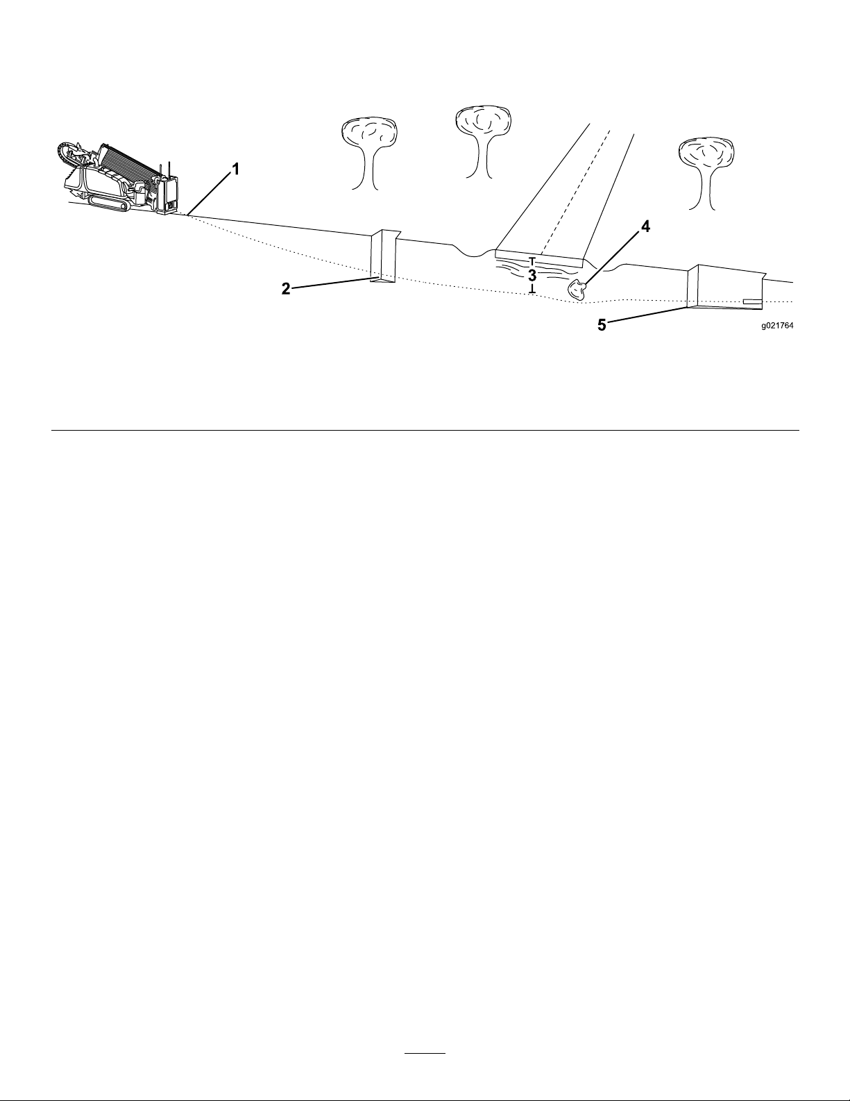
Beforesettingupthejobsite,youneedtoplantheborepath,
includingthefollowing:
Figure48
1.Boreentry
2.Beginning-of-bore-at-depthpoint5.End-of-bore-at-depthpointandboreexit
3.Boredepth
•Boreentry
Theisthelocationwhereyousetupthemachineandthe
drillbitenterstheground.Dependingonconditions,this
willtypicallybesetback9to15m(30to50ft)fromthe
beginning-of-the-bore-at-depthpoint.
•Beginning-of-bore-at-depthpoint
Thisisthepointwhereyouwanttheutilitylineorpipeto
endafterinstallationiscomplete.Itistypicallythepointat
whichtheborelevelsoutandbeginstoborehorizontally.
Thismaybethesameastheentrypoint,oryoumaydiga
separatedepth-gaugeholeatthispoint(Figure48).
•Boredepth
Thisthedepthatwhichyouwanttoinstalltheutility
lineorpipe.Thismachineisdesignedprimarilyfor
installationsbetween1and3m(3.5to10ft).
•Obstaclesinthepath
Itisimportanttoknowwheretheknownobstaclesare
thatyouwillneedtosteeraroundorunderbeforestarting
sothatyoucanplanwheretobeginsteeringpriorto
reachingtheobstacle.
•End-of-bore-at-depthpoint
Thisisthepointwhereyouwanttheutilitylineorpipe
tobeginafterinstallationiscomplete.Oftenthiswillalso
betheboreexit.
4.Obstacle
neededforsteeringthedrilltothesurface,typically9to15
m(30to50ft)fromtheend-of-the-bore-at-depthpoint.
DeterminingtheBoreEntryPoint
Oneofthemorechallengingaspectsofplanningthebore
pathistodeterminetheentrypointofthebore.Youneedto
takethefollowingtraitsintoaccountwhendeterminingthe
locationoftheentrypoint:
•Boredepth
Thisthedepthatwhichyouwanttoinstalltheutility
lineorpipe.Thismachineisdesignedprimarilyfor
installationsbetween1and3m(3.5to10ft).
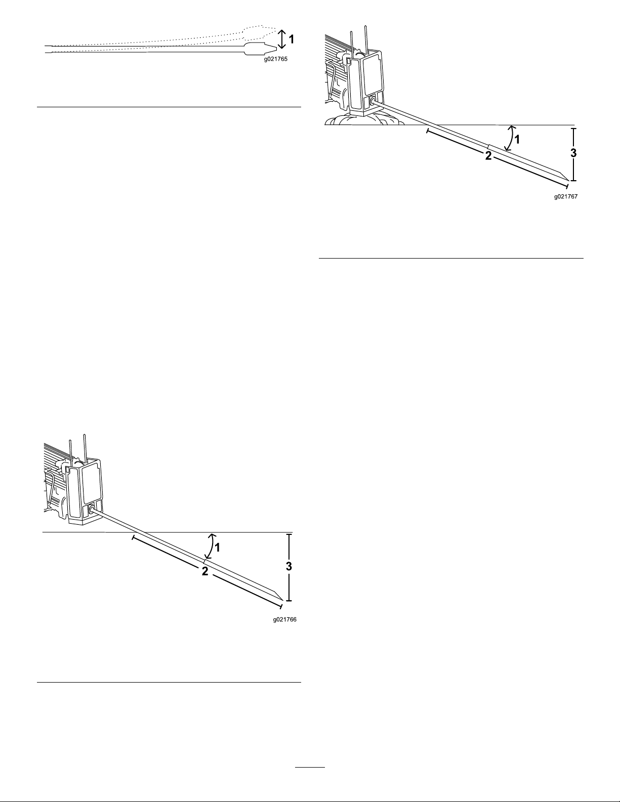
•Pipeandmaterialexibility
The3m(10ft)pipesusedonthismachinecanextoan
8%pitchoverthelengthofthepipe;thisequatestoa
bendofnomorethan20cm(8inches)offofastraight
path(Figure49).
Important:Ifyousteerthepipetobendsharper
than20cm(8inches)perpipe,youmaydamagethe
pipesandtheirconnections.Youmustalsomake
steeringchangesgraduallyovertheentirelengthof
eachpipe.Ifyousteerthewhole20cm(8inches)
inonly25to50cm(1to2ft)oftravel,youwill
permanentlydamagethepipes.
•Boreexit
Thisisthelocationwherethedrillheadwillexitthe
groundandthepointatwhichyouwillpulltheutilitylines
orpipeintothebore.Ifthispointwillbeatthesurface
insteadofatinstallationdepth,youwillneedtodetermine
thedistancefromtheend-of-bore-at-depthlocation
43
Page 44
1
g021765
Figure49
1
2
3
g021766
2
3
g021767
1
1.20cm(8inches)
Thisexibilityisoftenratedinmaterialsasaminimum
bendradius,whichistheradiusofthecircleformedifthe
materialorpipes,connectedtogether,werebenttoform
agiantcircle.Theminimumradiusofacirclemadewith
thepipeusedwiththismachineis36.6m(102ft).
•Entrypitch
Theentrypitchistheangleatwhichthemachine
enterstheground.Withthetracksonlevelground,the
stabilizersdown,andthestake-downplateontheground,
thedrillframeangleisabout15degreesora27%pitch.
Thispitchwillchangedependingontheslopeofthe
groundandotherfactorsofthejobsite.Youcanalso
reducethispitchabitbybuildingupthegroundunder
thestake-downplatebeforepositioningthemachine.
Youcandeterminetheactualpitchofthedrillframeby
placingthedrillbitandsondehousingontheframeand
thenusethereceivertodisplaythepitch.
Thesteeperyourentrypitchis,thedeeperyourborewill
havetobeduetothelimitationsofthepipeexibility.
Typicallyyouneedtoinsertthedrillandatleast1/3ofa
pipeintothegroundbeforeyoucanstartsteeringtoward
thebeginningoftheborepoint.Figure50,Figure51,
andthefollowingtableillustratetherelationshipbetween
entrypitchanddepth.
Figure51
1.18%pitch3.53cm(21inches)
2.3m(10ft)
Figure50
1.26%pitch3.76cm(30inches)
2.3m(10ft)
44
Page 45

Note:Thedepthsgiveninthefollowingtablearefor3m(10ft)ofcombineddrillheadandpipe.Asyousteerup,the
pitchofthesteeredsectionwillchangeandcanbemonitoredwiththereceiver.Usethefollowingtabletoidentifyhow
manylengthsofpipewillbenecessarytoinsertandsteertothebeginningpointandhelpyouchooseanentrypoint.
Pitch
1%2cm(1inch)26%76cm(30inches)
2%5cm(2inches)27%79cm(31inches)
3%10cm(4inches)28%81cm(32inches)
4%13cm(5inches)29%84cm(33inches)
5%15cm(6inches)30%86cm(34inches)
6%18cm(7inches)31%91cm(36inches)
7%20cm(8inches)32%94cm(37inches)
8%25cm(10inches)33%97cm(38inches)
9%28cm(11inches)34%99cm(39inches)
10%30cm(12inches)35%102cm(40inches)
11%33cm(13inches)36%104cm(41inches)
12%36cm(14inches)37%107cm(42inches)
13%39cm(15inches)38%109cm(43inches)
14%43cm(17inches)39%112cm(44inches)
15%46cm(18inches)40%114cm(45inches)
16%48cm(19inches)41%117cm(46inches)
17%51cm(20inches)42%117cm(46inches)
18%53cm(21inches)43%119cm(47inches)
19%56cm(22inches)44%122cm(48inches)
20%61cm(24inches)45%124cm(49inches)
21%64cm(25inches)46%127cm(50inches)
22%66cm(26inches)47%130cm(51inches)
23%69cm(27inches)48%133cm(52inches)
24%71cm(28inches)49%135cm(53inches)
25%74cm(29inches)50%137cm(54inches)
Allmeasurementsareapproximateandwillvarydependingonsoilconditions.
DepthChangeper10feet
Pitch
DepthChangeper10feet
Note:ThesevaluesandmorecanbefoundintheDriller’ sHandbook&DailyLogbyDigitalControlIncorporated.
45
Page 46
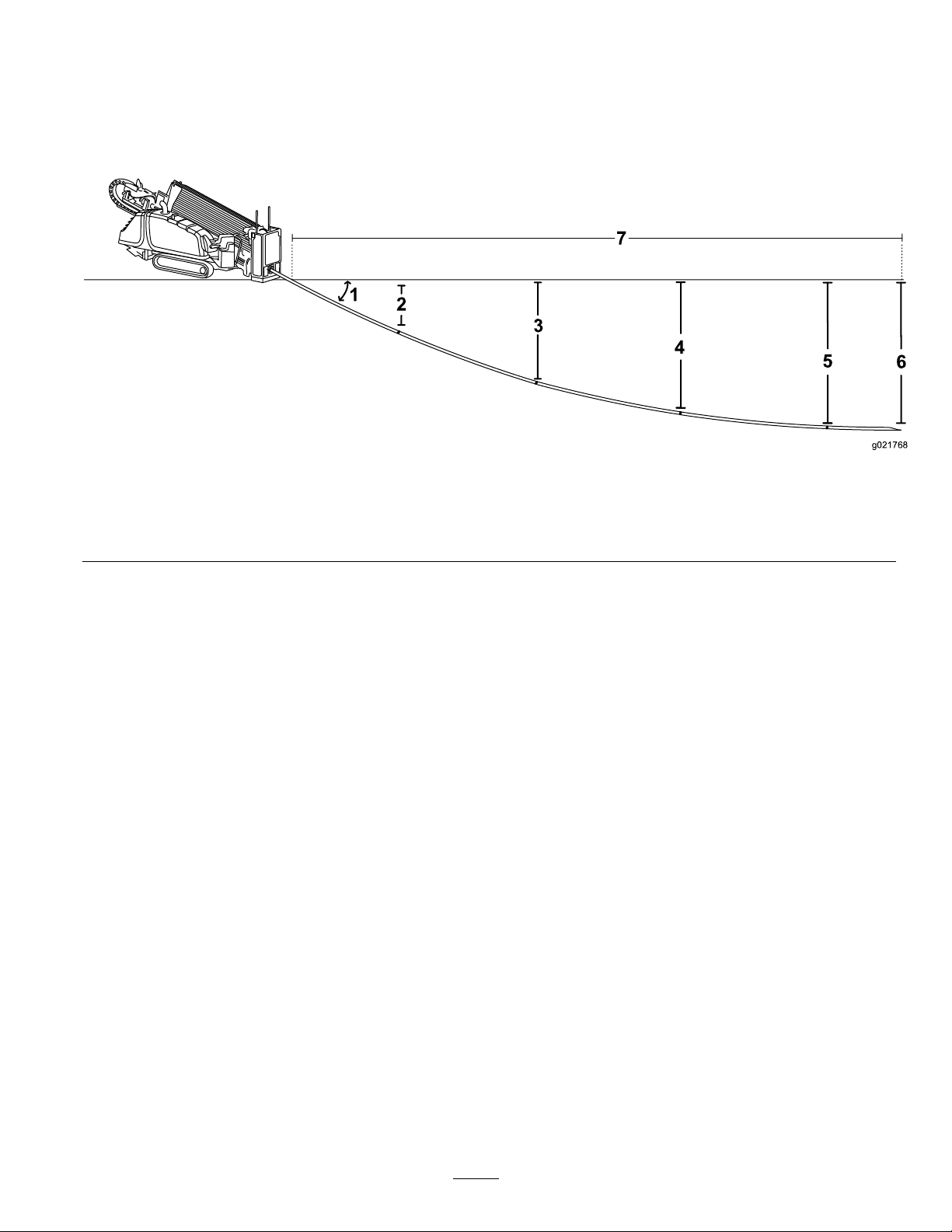
Giventheaboveinformation,youcancalculatethenumberof
1
4
2
3
5
g021768
7
6
rodsrequiredtoreachyourbeginningpointattheappropriate
depth.Tororecommendsthatyoustarttheentrypointa
distancebackfromyourbeginning-at-depthpointbythe
samedistanceasthelengthofpipesyouwillneedtoreach
thatpoint.Thiswillensurethatyouhaveenoughextraspace
soyouwillnotneedtoover-steeranddamagethepipes.
1.26%pitch4.185cm(73inches)7.14.7m(45ft)
2.76cm(30inches)5.203cm(80inches)
3.142cm(56inches)6.208cm(82inches)
Thefollowingexampleillustratestheprocessgivenan
installationusingthemaximumentrypitchofthemachine
(26%)onlevelground:
•Youinserttherst3m(10ft)ofdrillbit/pipeintothe
groundwithnosteering.Theendofthedrillbitwillbe
76cm(30inches)deep(Figure49).
Figure52
•Youbeginsteeringupforthenext3m(10ft),pushingthe
pipesinatthemaximumpitchchangeof8%.Thisresults
inachangeofpitchfrom26%atthebeginningofthe3m
(10ft)to18%attheendofthe3m(10ft)foranaverage
pitchof22%.Giventhat,thedrillheadlowersanother66
cm(26inches)andisnow142cm(56inches)deep.
•Continuingsteeringupforthenext3m(10ft)atan8%
pitchchange,yourpitchwillchangefrom18%to10%
foranaveragepitchof14%.Giventhat,thedrillhead
lowersanother43cm(17inches)andisnow185cm(73
inches)deep.
•Continuingsteeringupforthenext3m(10ft)atan8%
pitchchange,yourpitchwillchangefrom10%to2%for
anaveragepitchof6%.Giventhat,thedrillheadlowers
another18cm(7inches)andisnow203cm(80inches)
deep.
•Levelingthedrillheadfrom2%to0%takeslessthan1.5
m(5ft)moreforanaldepthof208cm(82inches).
Reachingthisnalpointtookfourandahalf,3m(10ft)
pipes.Soforthisexampleyourentrypointshouldbe
14.7m(45ft)backfromthebeginning-at-depthpointof
yourinstallation.
46
Page 47
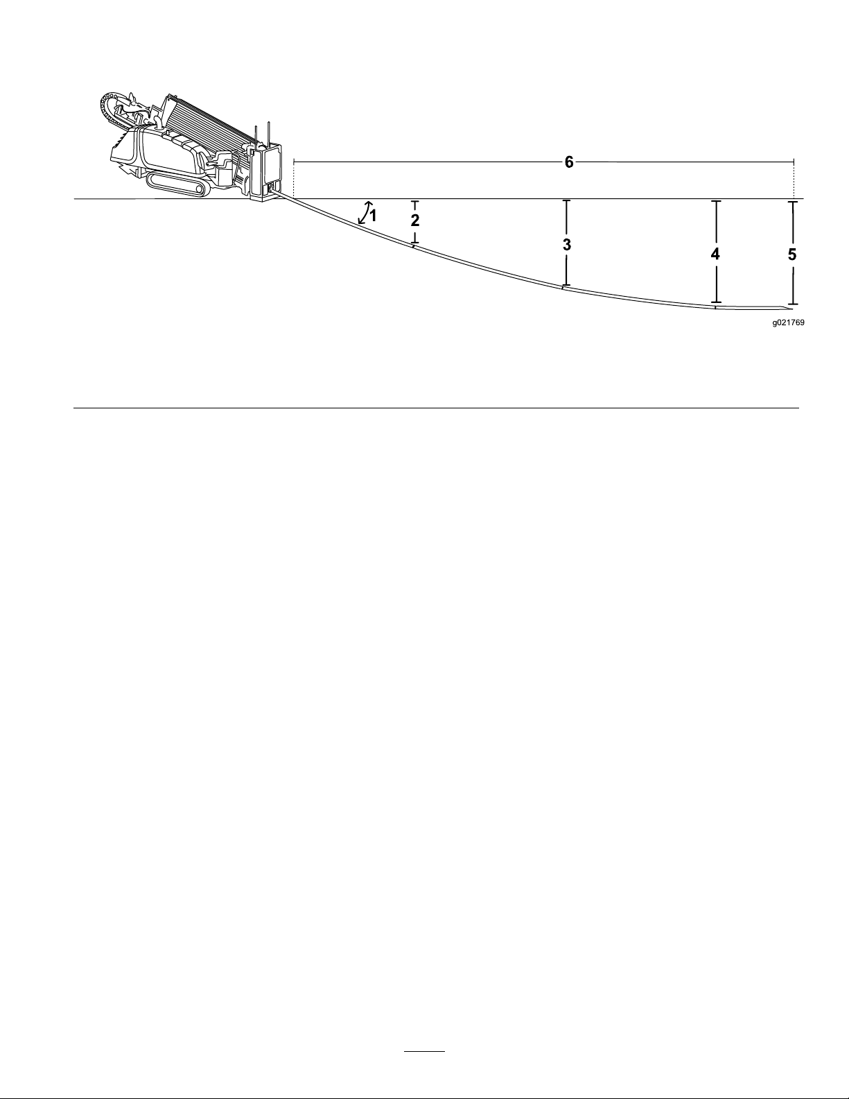
Thefollowingexampleillustratestheprocessgivenan
1
2
3
4
g021769
6
5
installationusingthemachineatan18%pitchonlevel
ground:
1.18%pitch3.96cm(38inches5.119cm(47inches)
2.53cm(21inches)4.114cm(45inches)6.10.6m(35ft)
•Youinserttherst3m(10ft)ofdrillbit/pipeintothe
groundwithnosteering.Theendofthedrillbitwillbe
53cm(21inches)deep(Figure53).
Figure53
•Youbeginsteeringupforthenext3m(10ft),pushingthe
pipesinatthemaximumpitchchangeof8%.Thisresults
inachangeofpitchfrom18%atthebeginningofthe3m
(10ft)to10%attheendofthe3m(10ft)foranaverage
pitchof14%.Giventhat,thedrillheadlowersanother43
cm(17inches)andisnow96cm(38inches)deep.
•Continuingsteeringupforthenext3m(10ft)atan8%
pitchchange,yourpitchwillchangefrom10%to2%for
anaveragepitchof6%.Giventhat,thedrillheadlowers
another18cm(7inches)andisnow114cm(45inches)
deep.
•Levelingthedrillheadfrom2%to0%takeslessthan1.5
m(5ft)moreforanaldepthof119cm(47inches).
Reachingthisnalpointtookthreeandahalf,3m(10
ft)pipes.Soforthisexampleyourentrypointshouldbe
10.6m(35ft)backfromthebeginning-at-depthpointof
yourinstallation.
Important:Youcanusetheinformationcontainedin
thissectiontodetermineboththespaceneededtosteer
uptotheexitpointifneededandalsotosteeraround
obstacles.
MappingtheBore
Withtheinformationyougatheredpreviously,mapoutthe
routeofthebore,identifyingthefollowingsothatyoucan
markthesitelater:
•Entrypoint
•Locationofthemachineandsupportingequipment
•Beginningofboreatdepth
•Anyobstaclesthatyouneedtosteeraroundandthe
locationswhereyouneedtostartsteeringtogetaround
orunderthem
•Anyutilitylinesyouwillneedtocross
•Slopeandsoilchangesalongthepaththatwillaffectthe
bore
•Endoftheboreatdepth
•Exitlocationifdifferentthantheendofthebore
47
Page 48
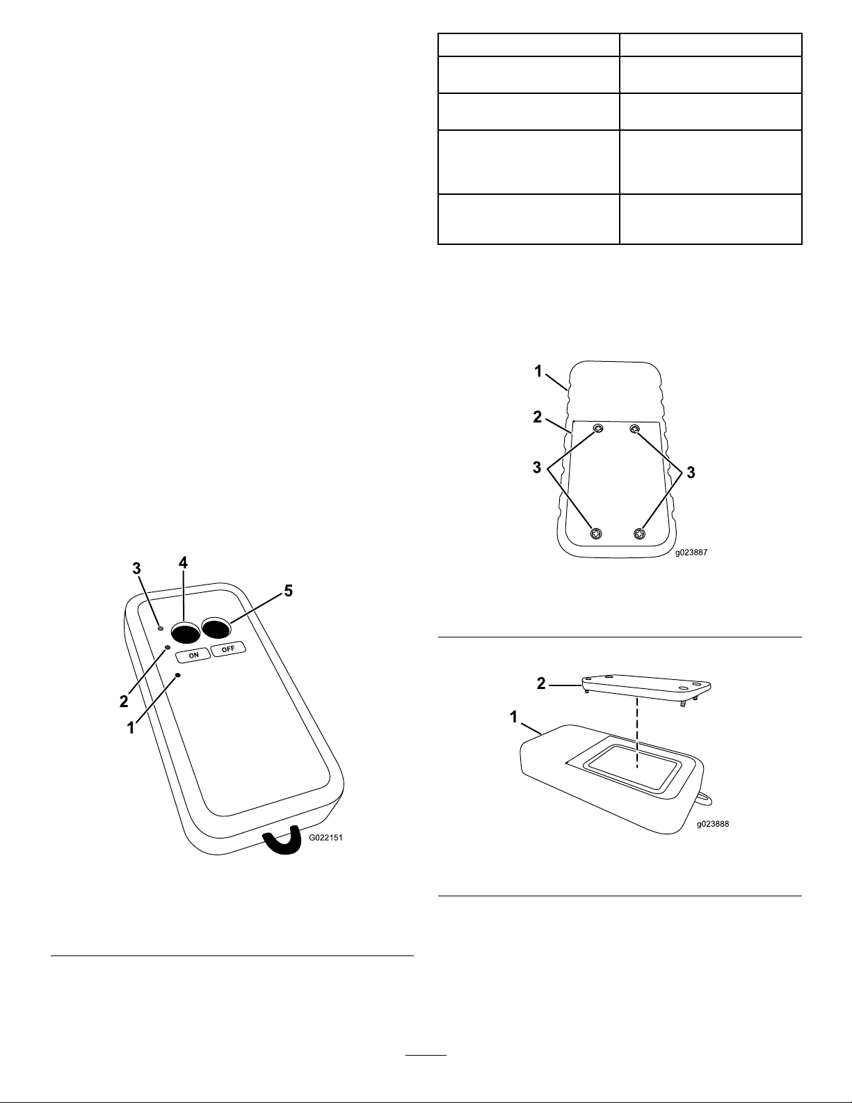
UnderstandingandUsing
ON
OFF
1
2
3
4
5
G022151
theExit-side-lockoutSystem
(StandardRange)
UnderstandingandUsingtheHandheld
Transmitter(StandardRange)
TheindividualholdingthetransmittercanpushtheLock
Drill(Off)buttontostopthedrillrotationandthrust.This
isprimarilyusedtostop/lockoutthedrilloperationsinthe
followingsituations:
IndicatorLightState
Greenlightisblinkingrapidly
Greenlightisilluminated
withoutblinking
YellowlightisblinkingslowlyThebatteriesarelow;change
RedlightisblinkingThetransmitterisactively
Meaning
Thetransmitteristransmitting
tothebaseunit
Abuttononthetransmitteris
currentlypressed
thebatteries.Ifyoudonot
changethebatteriessoon,the
handheldwillpowerdown.
receivingmessagesfromthe
baseunit.
•Wheninstallingorremovingadrillheadorreamer
•Wheneversomeoneneedstoapproachthedrillpipeor
headanywhereinfrontofthemachine
•Placingawiperonthedrillpipe
•Whenthelocationreceiveroperatoridentiesaproblem
requiringimmediateshutdownofdrilling
Whenitissafetoresumedrilling,theindividualholdingthe
transmittercanpresstheUnlockDrill(On)button.This
buttonsendsasignaltothereceiverthatallowsthemachine
operatortoresetthesystemandrestorethethrustandrotary
functions.
Thefollowingtableliststhevariousstatesoftheindicator
lightsonthehandheldtransmitter(Figure54)andtheir
meanings:
ReplacingtheHandheldTransmitter
Batteries(StandardRange)
1.Loosenthe4screwssecuringthebatterycover(Figure
55).
Figure55
1.Handheldtransmitter
2.Batterycover
2.Removethecover(Figure56).
3.Screws
1.Redindicatorlight
2.Yellowindicatorlight
3.Greenindicatorlight
Figure54
4.Onbutton
5.Offbutton
1.Handheldtransmitter2.Batterycover
3.Removetheexistingbatteries.
Figure56
4.Install3new,AAAbatteriesintheorientationshown
inFigure57.
Important:Ensurethatyouinstallthebatteries
inthecorrectpolarityorientationoryoucould
damagethetransmitter.
48
Page 49
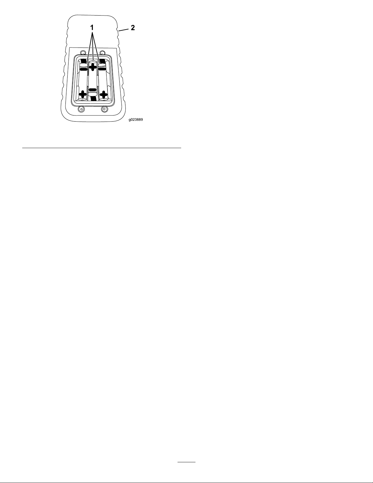
8.ReleasetheOnbutton.
TheRedlightturnsoffandtheGreenlightashesfor
afewseconds.
DisassociatingallHandheld
TransmittersfromtheBaseUnit
(StandardRange)
Important:Completingthisprocedurewilldisassociate
alltransmittersfromthebaseunit,whichwillneedtobe
associatedagainbeforetheywillfunction.
1.Ensurethatthemachineisturnedoff.
Figure57
1.Handheldtransmitter2.AAAbatteries
5.Replacethecoverandsecureitwiththescrewremoved
previously.
Tightenthescrewsenoughtoensurethatthesealing
gasketiscompressed,butdonotovertightenthem.
AssociatingtheHandheldTransmitter
withtheBaseUnit(StandardRange)
Ifthehandheldtransmittereverstopscommunicatingwith
thebaseunit,orifyoureplaceitwithanewtransmitter,you
needtoassociatethetransmittertothebaseunitasfollows:
1.Ensurethatthemachineisturnedoff.
2.Ensurethatthehandheldtransmitterisnotactive(i.e.,
nolightsareon).
3.Standneartherearcontrolpanelofthemachine.
4.SimultaneouslypressandholdtheOnandOffbuttons.
TheGreenlightilluminates.
5.ContinueholdingthebuttonsuntiltheYellowlight
beginsashing,thenreleasethebuttons.
TheRedlightbeginsashingallowingyou2seconds
topressthenextbutton.
6.PressandholdtheOnbutton
TheRedlightturnsoffandtheGreenandYellow
lightsilluminate.
2.Ensurethatthehandheldtransmitterisnotactive(i.e.,
nolightsareon).
3.Standneartherearcontrolpanelofthemachine.
4.SimultaneouslypressandholdtheOnandOffbuttons.
TheGreenlightilluminates.
5.ContinueholdingthebuttonsuntiltheYellowlight
beginsashing,thenreleasethebuttons.
TheRedlightbeginsashingallowingyou2seconds
topressthenextbutton.
6.PressandholdtheOffbutton
TheRedlightturnsoffandtheGreenandYellow
lightsilluminate.
Important:Ifyoudonotpressthisbuttonwithin
2seconds,youwillhavetostartthisprocedure
overagain.
7.ContinueholdingtheOffbuttonandturnonthe
machinetopowerthebaseunit.
Thebaseunitandhandheldestablishacommunication
linkwhileyouholdthebutton.Oncetheprocessis
complete,theY ellowlightturnsoff,theRedlight
beginsashing,andtheGreenlightilluminates.All
lightsremainasmentioneduntilyoureleasethebutton.
8.ReleasetheOffbutton.
TheRedlightturnsoffandtheGreenlightashesfor
afewseconds.
Important:Ifyoudonotpressthisbuttonwithin
2seconds,youwillhavetostartthisprocedure
overagain.
7.ContinueholdingtheOnbuttonandturnonthe
machinetopowerthebaseunit.
Thebaseunitandhandheldestablishacommunication
linkwhileyouholdthebutton.Oncetheprocessis
complete,theY ellowlightturnsoff,theRedlight
beginsashing,andtheGreenlightilluminates.All
lightsremainasmentioneduntilyoureleasethebutton.
49
Page 50
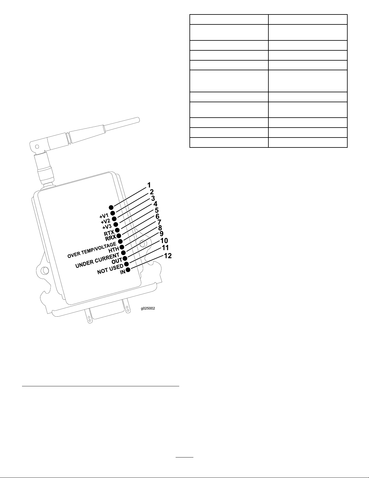
UnderstandingandUsing theExit-side-lockoutSystem (LongRange)
UnderstandingtheBase-unit
TransmitterIndicatorLights(Long
Range)
Thefollowingtableliststhevariousstatesoftheindicator
lightsonthebase-unittransmitter(Figure58)andtheir
meanings:
IndicatorLightMeaning
UnmarkedindicatorlightInputpowerpolarityreverse
+V1to+V3
RTXBlinkingwhentransmitting
RRXActivewhenreceiving
Overtemp/voltage
HTH
UndercurrentLightsupwhenthecurrentis
OutOutputisactivewhenlit
NotusedUnused
InInputisactivewhenlit
whenlit
OKandactivewhensolid
Lightsupwhenthe
temperatureorvoltageis
exceeded
OKwhenblinking
toolow
Figure58
1.Polarity-reversalindicator
2.+V18.HTH
3.+V29.Undercurrent
4.+V3
5.RTX11.Notused
6.RRX12.In
7.Overtemperature/voltage
10.Out
50
Page 51
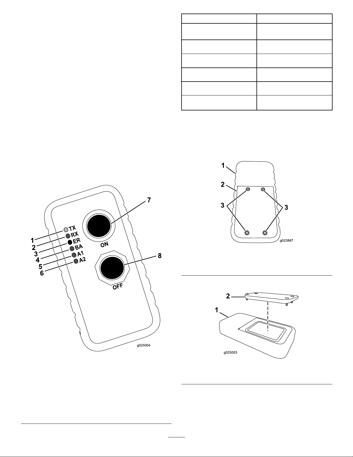
UnderstandingandUsingtheHandheld
TransmitterIndicatorLights(Long
Range)
TheindividualholdingthetransmittercanpushtheLock
Drill(Off)buttontostopthedrillrotationandthrust.This
isprimarilyusedtostop/lockoutthedrilloperationsinthe
followingsituations:
•Wheninstallingorremovingadrillheadorreamer
•Wheneversomeoneneedstoapproachthedrillpipeor
headanywhereinfrontofthemachine
•Placingawiperonthedrillpipe
•Whenthelocatoroperatoridentiesaproblemrequiring
immediateshutdownofdrilling
IndicatorLightState
Thegreentransmit(TX)light
isblinkingrapidlyandisdim.
Thegreentransmit(TX)light
isblinkingrapidlyandisbright.
Theyellowreceive(RX)light
isblinkingrapidlyandisbright.
Therederror(ER)lightis
solidlylit.
Theyellowlowbattery(BA)
lightisslowlyblinking.
Theyellowauxiliary1and2
(A1andA2)lightsarelit.
Meaning
Thehandheldistransmitting
tothebaseunit.
Thebuttonsonthehandheld
arenowactive.
Thehandheldisreceiving.
Anerrorisoccurring.
Thebatteriesforthehandheld
arerunninglow.
Themachineandhandheld
areunused.
Whenitissafetoresumedrilling,theindividualholdingthe
transmittercanpresstheUnlockDrill(On)button.This
buttonsendsasignaltothereceiverthatallowsthemachine
operatortoresetthesystemandrestorethethrustandrotary
functions.
Thefollowingtableliststhevariousstatesoftheindicator
lightsonthehandheldtransmitter(Figure59)andtheir
meanings:
ReplacingtheHandheldTransmitter
Batteries(LongRange)
1.Loosenthe4screwssecuringthebatterycover(Figure
55).
Figure60
1.Handheldtransmitter
2.Batterycover
2.Removethecover(Figure61).
3.Screws
1.Transmit(TX)—green
indicatorlight
2.Receive(RX)—yellow
indicatorlight
3.Error(ER)—redindicator
light
4.Lowbattery(BA)—yellow
indicatorlight
Figure59
5.Auxiliary1(A1)—yellow
6.Auxiliary2(A2)—yellow
7.Onbutton
8.Offbutton
indicatorlight
indicatorlight
Figure61
1.Handheldtransmitter2.Batterycover
3.Removetheexistingbatteries.
4.Install3new,AAAbatteriesintheorientationshown
inFigure57.
51
Page 52
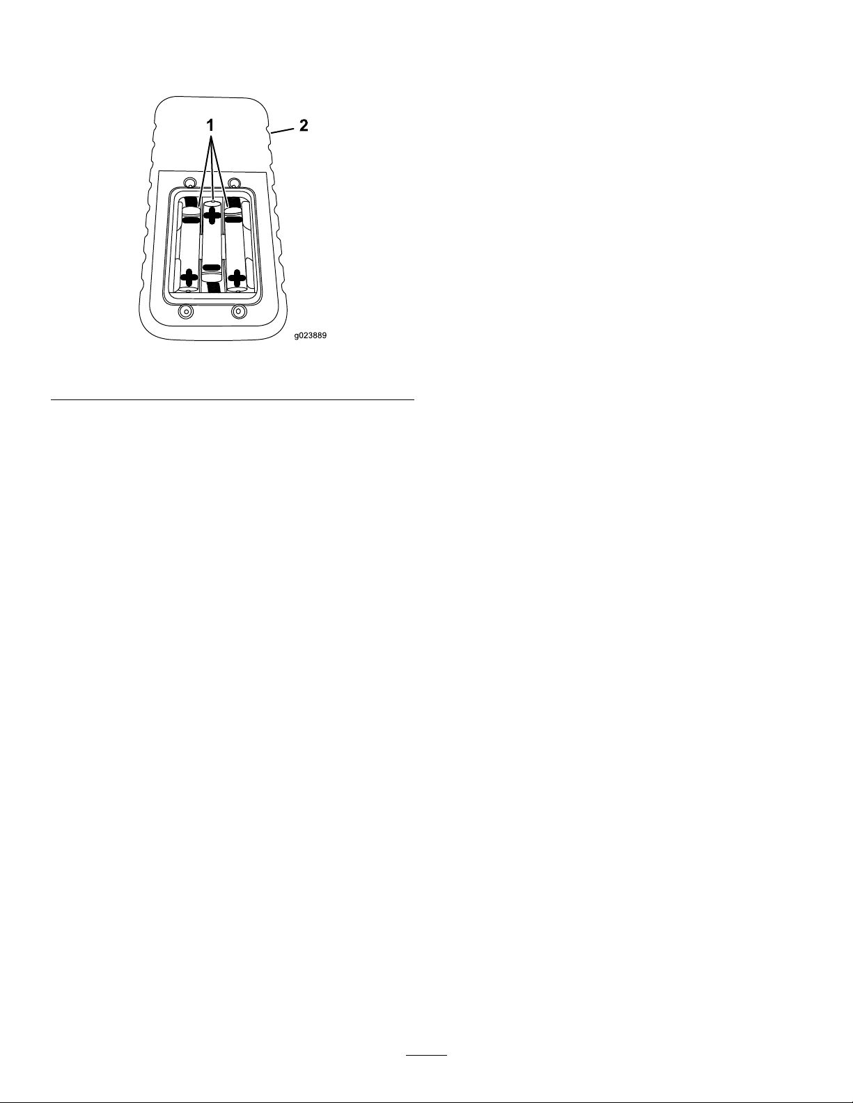
Important:Ensurethatyouinstallthebatteries
inthecorrectpolarityorientationoryoucould
damagethetransmitter.
Figure62
1.Handheldtransmitter2.AAAbatteries
5.Replacethecoverandsecureitwiththescrewremoved
previously.
Tightenthescrewsenoughtoensurethatthesealing
gasketiscompressed,butdonotovertightenthem.
AssociatingtheHandheldTransmitter
withtheBaseUnit(LongRange)
PreparingtheJobSiteandthe
Machine
Beforedrilling,preparethejobsiteandmachineasfollows:
•MarkandpreparetheborepathMarkingandPreparing
theBorePath(page52).
•TesttheZap-Alertsystem;refertoTestingtheZap-Alert
System(page53).
•Loadthedrillpipesintothepipeholderifneeded;refer
toLoadingDrillPipesintothePipeHolder(page55).
•Addfueltothemachine;refertoAddingFuel(page55).
•Checktheoillevelintheengine;refertoCheckingthe
Engine-oilLevel(page81)
•Checktheenginecoolantlevel;refertoCheckingthe
CoolingSystem(page57).
•Checkthehydraulicoillevel;refertoCheckingthe
HydraulicFluid(page97).
•Checktheoillevelinthedrilling-uidpump;referto
CheckingtheDrilling-uid-pumpOilLevel(page100).
•Load/unloadthemachine;refertoLoadingand
UnloadingtheMachine(page58).
•Drivethemachinetotheentrypoint;referto
UnderstandingHorizontalDirectionalDrilling(page40).
•Connectthemachinetoadrilling-uidsource;referto
ConnectingtoaDrilling-uidSource(page61).
Ifthehandheldtransmittereverstopscommunicatingwith
thebaseunit,orifyoureplaceitwithanewtransmitter,you
needtoassociatethetransmittertothebaseunitasfollows:
1.Ensurethatthemachineisturnedoff.
2.Ensurethatthehandheldtransmitterisnotactive(i.e.,
nolightsareon).
3.Whileholdingthehandheldtransmitter,standnearthe
baseunitwithanunobstructed,clearline-of-sight.
4.SimultaneouslypressandholdtheOnandOffbuttons
(Figure59).
Note:AlloftheLEDlightsactivate.
5.ContinuouslyholdbothOnandOffbuttonsuntil
thegreentransmit(TX)indicatorlightbeginstoash
(Figure59).
6.TurnthemachineonwhilecontinuingtoholdOnand
Offbuttons(Figure59).
Note:TheTX,RX,ER,andBAindicatorlights
shouldash.
7.ReleasetheOnandOffbuttons(Figure59).
Note:TheTXandRXindicatorlightsshouldash.
•Setupthedrillbit(s)andtrackingelectronics;referto
SettingUptheDrillHeadandTrackingSystem(page58).
•Setupthemachinefordrilling;refertoSettingupthe
MachineforDrilling(page60).
•DeploytheZap-Alertsystem;refertoDeployingthe
Zap-AlertSystem(page62)
MarkingandPreparingtheBorePath
1.Walktheborepath,markingitonthegroundwith
markingpaintsothatthereceiveroperatorwillbeable
tofollowtheplan.
2.Handdigtoexposeanyburiedutilitylinesmarked
previouslythattheborepathwillbecrossing.This
willallowthereceiveroperatortoknowexactlywhere
theyare.
3.Ifyouareexitingtheboreatgroundlevelandnotinan
existingtrench,diganangledholeintowhichthebit
willenterattheendofthebore.
4.Ifdesired,digaholetothebeginning-of-the-borepoint
whereyoucandisconnectthepipeorlinesafterpulling
themback.
52
Page 53
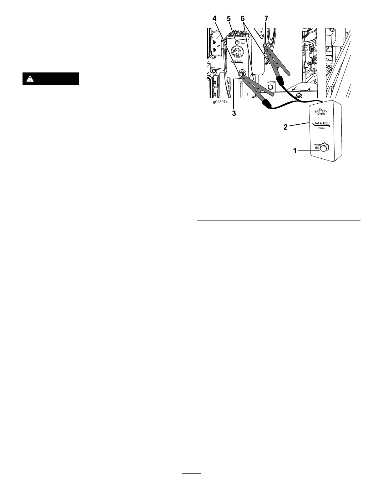
TestingtheZap-AlertSystem
TheZap-Alertsystemisanelectricstrikesensingdeviceon
themachinethattriggersastrobelightandaudiblealarmin
theeventthatthedrillbit,reamer,orstakebreaksintoan
energizedpowerline.Intheeventofanelectricstrike,the
machinewillbecomeenergized,settingoffthealarm.
DANGER
IftheZap-Alertsystemactivateswhiledrilling,the
machine,exceptfortheoperator’splatform,will
becomeenergized.Ifyoustepofftheoperator
platformorifsomeonetouchesthemachineorwet
groundnearthemachineorinthebore,youor
theycouldbeelectrocutedcausingseriousinjury
ordeath.
•TesttheZap-Alertsystembeforedrilling.
•Deploythegroundingstakebeforedrilling.
Ensurethatthestakeisfullyinsertedintomoist
soil.
•IftheZap-Alertistriggered:
–Stayintheseatanddonottouchtheground
oranyotherpartofthemachineuntilthe
powerhasbeenturnedoff.Donotpour
liquidsorurinatefromtheoperatorplatform
ontotheground.
–Stopdrilling,stopthedrilling-uidow,and
retractthedrilloutoftheground.
–Keepeveryoneawayfromthemachine.
–Keepstandingorrunningwateranddrilling
uidcontainedclosetothemachine.Keep
wateranddrillinguidsourcesawayfrom
thebrokenline.
–Contacttheutilitycompanytohavepower
shutofftothebrokenline.Donotresetthe
Zap-Alertsystemuntilthepowerhasbeen
turnedoff.
Figure63
1.Testbutton5.Resetbutton
2.Zap-alerttester6.Alligatorclips
3.Zap-alertsystem7.Machinegroundingpoint
4.Zap-alertsystem
groundingstud
4.Connecttheotheralligatorcliptoametalcomponent
ofthemachineframe.
5.PresstheTestbuttonontheZap-Alerttester(Figure
63).
TheZap-Alertalarmshouldsound,andthestrobeon
topofthefronthoodshouldash.
6.PresstheZap-Alertresetbuttontostopthealarm
(Figure63).
TesttheZap-Alertsystembeforeusingthedrilleachday,as
follows:
1.Openthefronthood;refertoOpeningtheFront
Hood(page72).
2.Laythegroundingstakeatonthegroundawayfrom
themachine.Donotdrivethestakeintotheground.
Important:Donotallowthestaketotouchany
partofthemachine.
3.ConnectanalligatorclipfromtheZap-Alerttesterto
thegroundingstudontheZap-Alertsystem(Figure
63).
53
Page 54
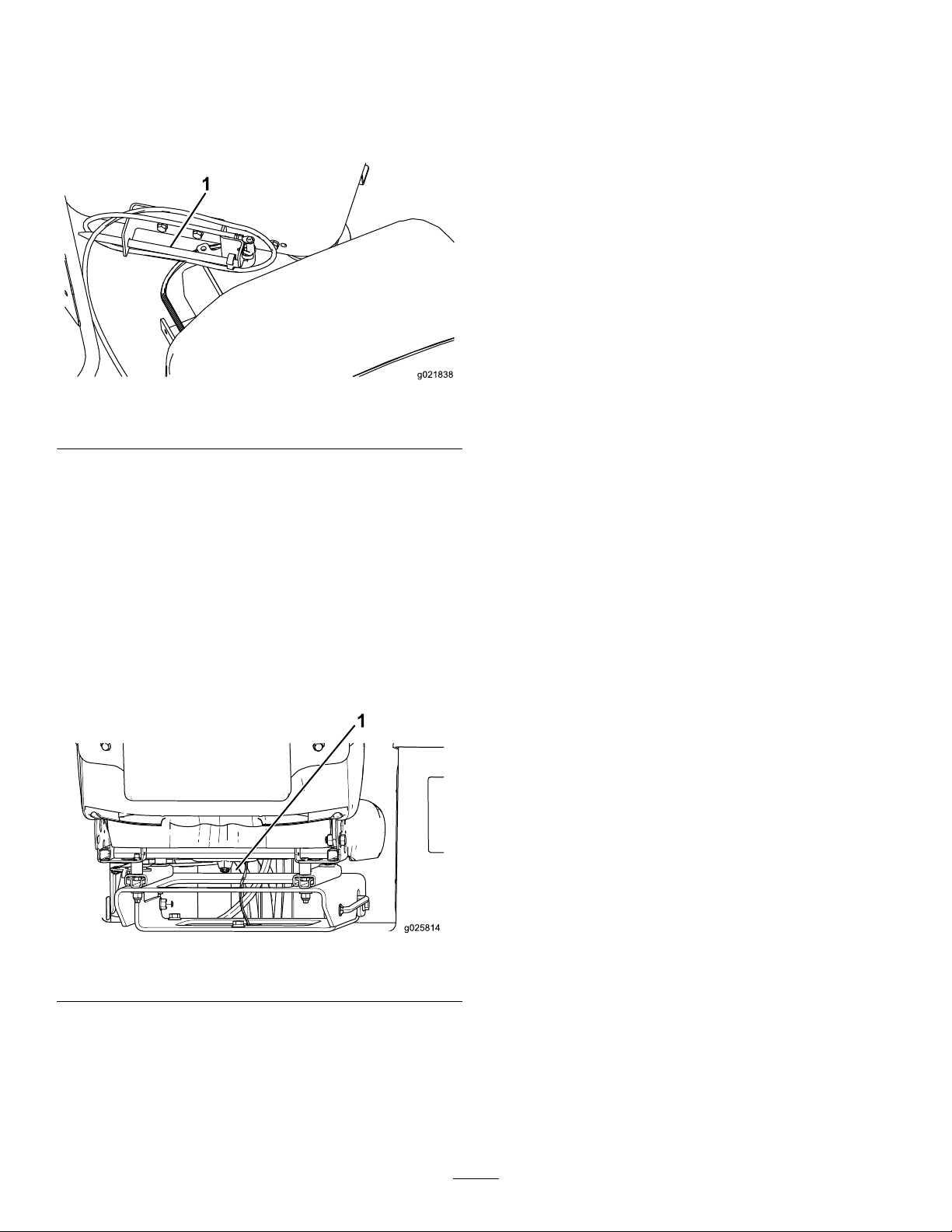
7.Disconnectthealligatorclipsfromthegroundingstud
g021838
1
andthemachine.
8.Storethegroundingstakeintheholderontheoperator
platformasshowninFigure64.
Figure64
1.Groundingstake
Ifeithertheaudiblealarmorthestrobelightfailedto
triggerwhenyoupressedthetestbutton,havethem
repairedbeforedrillingwiththemachine.
MountingaFireExtinguisher
Mountyourreextinguisherbelowtheoperatorseat(Figure
65).
Note:Areextinguisherisnotprovidedwiththemachine.
Therecommendedreextinguisherisadrychemicalre
extinguisherapprovedforclassBandCres.
Figure65
1.Mountinglocation
54
Page 55
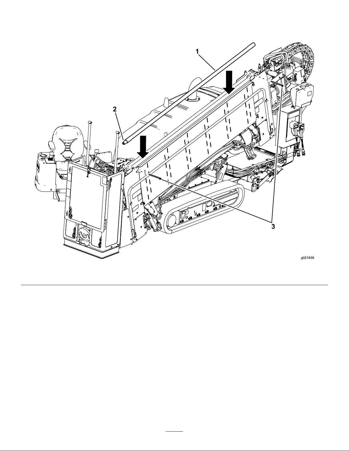
LoadingDrillPipesintothePipeHolder
Beforeusingthemachine,llthepipeholderwithupto40
drillpipes.
1.Pipe2.Maleend
1.Removetheclevispinsfromthepipeholder(Figure
66).
2.Insertthepipesfromthetopwiththemalethreaded
pipeendstowardthefrontofthemachine(Figure66).
3.Installtheclevispinsbeforedrilling.
Note:Beforedrilling,checktheconditionofthepipesand
replaceanythatarebentordamaged.
Figure66
3.Clevispins
AddingFuel
ServiceInterval:Beforeeachuseordaily—Checkthefuel
level.
Useonlyclean,freshdieselfuelorbiodieselfuelswithlow
(<500ppm)orultralow(<15ppm)sulfurcontent.The
minimumcetaneratingshouldbe40.Purchasefuelin
quantitiesthatcanbeusedwithin180daystoensurefuel
freshness.
Fueltankcapacity:114L(30USgallons)
Usesummergradedieselfuel(No.2-D)attemperatures
above-7°C(20°F)andwintergrade(No.1-DorNo.
1-D/2-Dblend)belowthattemperature.Useofwintergrade
fuelatlowertemperaturesprovideslowerashpointand
coldowcharacteristicswhichwilleasestartingandreduce
fuellterplugging.
55
Page 56
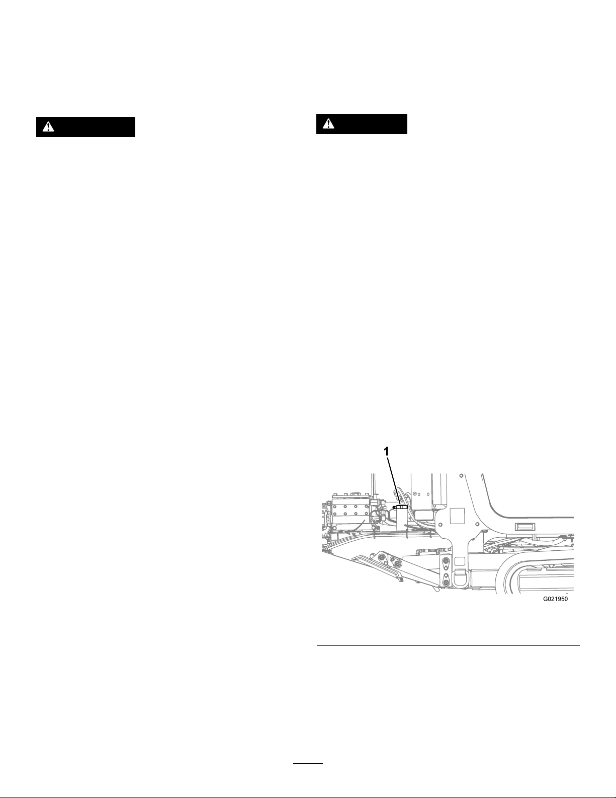
Useofsummergradefuelabove-7°C(20°F)willcontribute
towardlongerfuelpumplifeandincreasedpowercompared
towintergradefuel.
•Ifthisisnotpossible,thenrefuelsuchequipmenton
atruckortrailerfromaportablecontainer,ratherthan
fromafueldispensernozzle.
Important:Donotusekeroseneorgasolineinsteadof
dieselfuel.Failuretoobservethiscautionwilldamage
theengine.
WARNING
Fuelisharmfulorfatalifswallowed.Long-term
exposuretovaporscancauseseriousinjuryand
illness.
•Avoidprolongedbreathingofvapors.
•Keepfaceawayfromnozzleandgastankor
conditioneropening.
•Keepfuelawayfromeyesandskin.
BiodieselReady
Thismachinecanalsouseabiodieselblendedfuelofup
toB20(20%biodiesel,80%petrodiesel).Thepetrodiesel
portionshouldbeloworultralowsulfur.Observethe
followingprecautions:
•Thebiodieselportionofthefuelmustmeetspecication
ASTMD6751orEN14214.
•TheblendedfuelcompositionshouldmeetASTMD975
orEN590.
•Paintedsurfacesmaybedamagedbybiodieselblends.
•UseB5(biodieselcontentof5%)orlesserblendsincold
weather.
•Ifafueldispensernozzlemustbeused,keepthenozzlein
contactwiththerimofthefueltankorcontaineropening
atalltimesuntilfuelingiscomplete.
DANGER
Incertainconditions,fuelisextremelyammable
andhighlyexplosive.Areorexplosionfromfuel
canburnyouandothersandcandamageproperty.
•Fillthefueltankoutdoors,inanopenarea,when
theengineiscold.Wipeupanyfuelthatspills.
•Donotllthefueltankinsideanenclosedtrailer.
•Donotsmokewhenhandlingfuel,andstay
awayfromanopenameorwherefuelfumes
maybeignitedbyaspark.
•Storefuelinanapprovedcontainerandkeepit
outofthereachofchildren.Donotbuymore
thana30-daysupplyoffuel.
•Donotoperatewithoutentireexhaustsystemin
placeandinproperworkingcondition.
1.Parkthemachineonalevelsurface.
2.Opentherearhood;refertoOpeningtheRear
Hood(page73).
3.Usingacleanrag,cleantheareaaroundfueltankcap.
4.Removethecapfromthefueltank(Figure67).
•Monitorseals,hoses,gasketsincontactwithfuelasthey
maybedegradedovertime.
•Fuellterpluggingmaybeexpectedforatimeafter
convertingtobiodieselblended.
•Contactyourdealerifyouwishformoreinformation
onbiodiesel.
Incertainconditionsduringfueling,staticelectricitycanbe
releasedcausingasparkwhichcanignitethefuelvapors.A
reorexplosionfromfuelcanburnyouandothersandcan
damageproperty.
•Placefuelcontainersonthegroundawayfromyour
vehiclebeforelling.
•Donotllfuelcontainersinsideavehicleoronatruck
ortrailerbedbecauseinteriorcarpetsorplastictruckbed
linersmayinsulatethecontainerandslowthelossofany
staticcharge.
•Whenpractical,removeequipmentfromthetruckor
trailerandrefueltheequipmentwithitstracksonthe
ground.
Figure67
1.Fuel-tankcap
5.Fillthetankuntilthelevelistothebottomoftheller
neckwithdieselfuel.
6.Installfueltankcaptightly .
Note:Ifpossible,llthefueltankaftereachuse.This
willminimizepossiblebuildupofcondensationinside
thefueltank.
56
Page 57

AdjustingtheCarriagePressure
1
ESC
2
3
4
5
6
7
8
OK
Machine Information
Lubrication and
Maintenance Chart
Read Error Codes
Diagnose and
Update System
Switch
Joystick
Functions
+
Air Hammer
Control: OFF
1
2
3
4
G021581
CheckingtheEngine-oilLevel
Tohydraulicallyadjustthecarriagepressure,dothefollowing:
1.Pressbutton7onthescreentoturnthecarriage
pressuretotheOnposition(green),asshowninFigure
68.
Figure68
1.Carriage-pressuregauge
2.Carriagepressureinthe
On(green)position
3.Increasecarriagepressure
4.Decreasecarriage
pressure
2.Increaseordecreasethecarriagepressureas
follows:(Figure69).
•Pressbutton5onthescreentodecreasethe
carriagepressure(Figure69).
•Pressbutton6onthescreentoincreasethe
carriagepressure(Figure69).
Note:Thecarriage-pressuregauge(Figure69)will
uctuateupordownbasedonhowmuchyouincrease
ordecreasethecarriagepressure.
Beforeyoustarttheengineandusethemachine,checktheoil
levelintheenginecrankcase;refertoCheckingtheEngine-oil
Level(page81)inEngineMaintenance.
CheckingtheCoolingSystem
Beforeyoustarttheengineandusethemachine,checkthe
coolingsystem;refertoCoolingSystemMaintenance(page
92).
CheckingtheHydraulic-uidLevel
Beforeyoustarttheengineandusethemachine,check
thehydraulicuidlevel;refertoCheckingtheHydraulic
Fluid(page97)inHydraulicSystemMaintenance.
Starting/StoppingtheEngine
Tostarttheengine,completethefollowing:
1.Openthefronthood;refertoOpeningtheFront
Hood(page72).
2.TurnthebatterydisconnectswitchtotheOnposition;
refertoBattery-DisconnectSwitch(page39).
3.Closeandlatchthehood.
4.Openthedoorontherearcontrolpanel.
5.TurntheignitionkeytotheRunposition.
IftheWait-to-Startlightilluminates,waituntilitturns
offbeforeproceeding.
6.TurntheignitionkeytotheStartpositionuntilthe
enginestarts,thenreleaseit.
Tostoptheengine,turntheignitionkeytotheOffposition.
Inanemergency,youcanalsostoptheengineandall
processesbypressingtheEngine-stopbuttononeitherthe
drivependantorthecontrolpanel.
1.Carriage-pressuregauge
2.Carriagepressureinthe
On(green)position
DrivingtheMachine
1.Walkaroundthemachinetoensurethatnooneisnear
it.Ensurethatallbystandersareclearoftheareawhere
youwillbemovingthemachine.
2.Connectthedrivependanttotherightreceptacleon
thebottomoftherearcontrolpanel.
3.Withthependantinhand,walkatleast6feettothe
sideofthemachine.Besuretokeepthissafedistance
Figure69
3.Increasecarriagepressure
4.Decreasecarriage
pressure
57
whenevermovingthemachine.
4.Pressandholdtheoperatorpresencebuttononthe
drivependant.
5.Usethespeedswitchonthependanttoincreaseor
decreasetheenginespeedasdesired.
6.Setthedesiredtravelspeed,usingthespeedswitch.
7.Usethejoysticktomovethemachineasdesired.
Note:Formoreinformationonthedrivependant,refer
toDrivePendant(page37).
Page 58
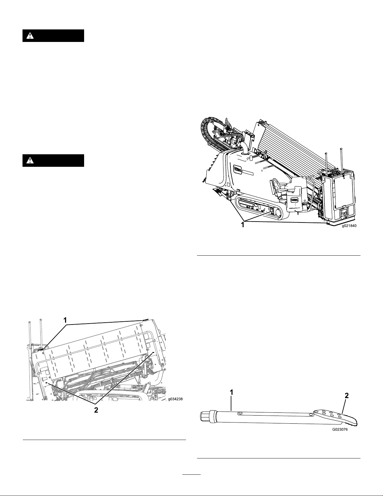
LoadingandUnloadingtheMachine
WARNING
Movingamachineofthissizeonatrailerover
publicroadscarriesriskstothosearoundthe
machineifitshouldcomeloose,beinvolvedinan
accident,hitalowhangingstructure,etc.
•Followthetie-downproceduresdescribedin
thissectionwhenmovingthemachine.
•Followalllocaltrafcregulationsgoverningthe
haulingoflargeequipment.Thismanualcannot
adequatelycoveralllawsandsafetyregulations;
itisyourresponsibilitytoknowandfollowthe
lawsandregulationsthatpertaintoyou.
WARNING
Themachinecanslipandfallfromatrailerorramp,
crushinganyonecaughtbeneathitandcausing
seriousinjuryordeath.
•Keepallbystandersawayfromthemachineand
trailer.
4.Usingthedrivependant,settheenginespeedtoslow
andthedrivespeedtoslow.
5.Usingthedrivependant,carefullydrivethemachine
forwardorrearwarduptherampandintopositionon
thetrailer.
6.Lowerthestake-downplatetothedeckofthetrailer.
7.Turnofftheengine.
8.Useappropriatelyratedchainsandbinderstosecure
theringsontheleftandrighttrackframesandthe
stake-downplatetothetrailer(Figure71).
•Ensurethatthetrailerandramparenotslippery
andarefreeofice,grease,oil,etc.
•Movethemachineontotherampatslowspeed
withtheengineatslowspeed.
•Ensurethatyouhavethemachinecenteredon
therampandtrailer.
1.Ensuretherampandthetrailerortruckbedcan
supporttheweightofthemachine.
2.Ensurethattheupperandrearpipe-holderpinsare
installedFigure70.
Figure71
1.Tie-downpoints(onlyrightsideshown)
9.Measurethedistancefromthegroundtothehighest
pointonthemachineforreferencetoensurethatyou
donotcollidewithlowhangingobstacles.
10.Removetheblockfromthetrailertires,andstowthem
withthemachineforusewhenunloadingit.
11.Afterdrivingafewmiles,pulloverandchecktoensure
thatallchainsarestilltightandthatthemachinehas
notmoved.
Tounloadthemachine,reversetheaboveprocedure.
SettingUptheDrillHeadandTracking
System
Thedrillheadconsistsoftwoparts,thedrillbitandthesonde
housing(Figure72).
Figure70
1.Upperpins2.Lowerpins
3.Placeablockatthefrontandrearofthetrailerand/or
trucktires.
Figure72
1.Sondehousing
58
2.Drillbit
Page 59
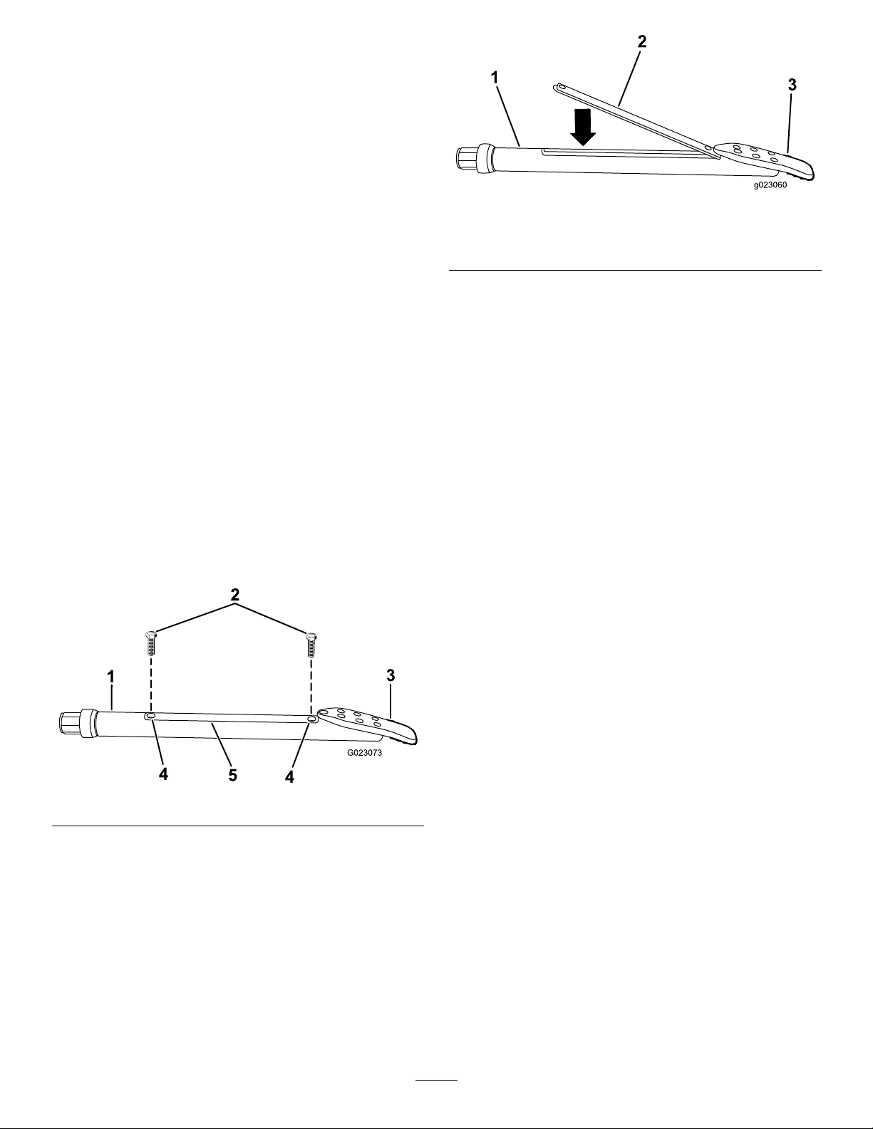
Drillbitsvaryinsizeandtypetomeetthevarioussoil
conditionsyoumayneedtodrillthrough.Someofthe
possibilitiesareasfollows:
•Straightblade—Usedinawiderangeofmediumdensity
soils.
•Bentblade—Usedinmediumtosoftsoils.Thisbithas
anadded20°bendtoincreasesteeringperformancein
softsoils.
•Trianglepointblade—Useinhardandrockysoils.This
bithascarbideedgestoreducewear.
Alloftheabovebitscomeinvaryingwidths.Awiderblade
increasesyourabilitytosteerinsoftsoils.Anarrowerblade
movesthroughhardsoilsbetter.ContactyourAuthorized
ToroDealerforacompletelistofavailableblades.
Thesondesandreceiversareessentialtotracktheposition
ofthedrillheadthroughoutthedrillingoperation.The
sondehousingonthedrillheadopensuptoacceptthesonde
beaconwhichworkswiththereceivertotrackthelocation,
pitch,direction,headorientation,andmoreofthedrillhead.
RefertotheTrackingSystemOperator’sManualforinstructions
onusingthesystem.
Figure74
1.Sondehousing
2.Sondebeacon
3.Drillbit
4.Installthehousingcoverandsecureitwiththescrews
(Figure73).
Toinstallthesondebeaconintothesondehousingonthe
drillhead,completethefollowing:
1.Replacethebatteriesinthesondebeaconasdescribed
intheTrackingSystemOperator’sManual.
2.Loosenthescrewssecuringthehousingcovertothe
housingandremovethecover(Figure73).
Figure73
3.Insertthesondebeaconwiththeforwardendtoward
thedrillbitintothesondehousing(Figure74).
59
Page 60
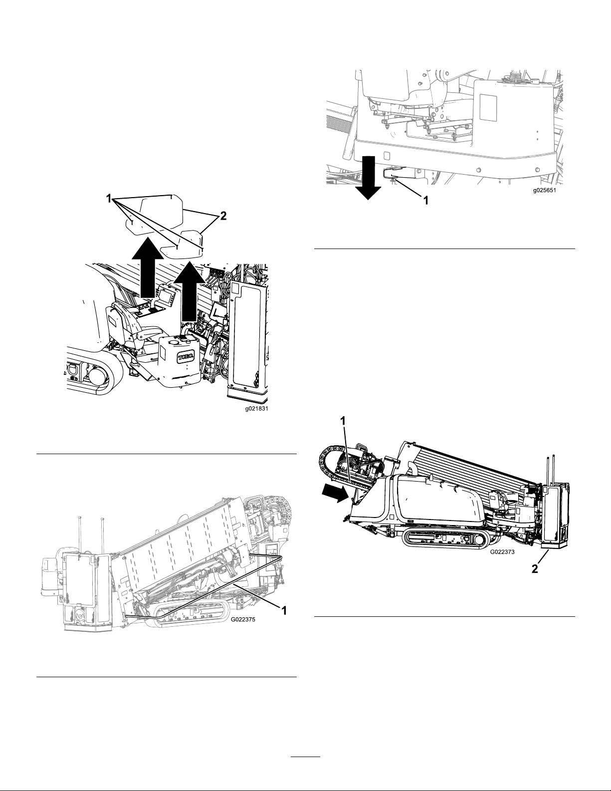
SettinguptheMachineforDrilling
1.Usingthedrivependant,drivethemachinetothe
locationthatyouhavepreparedforit,ensuringthat
thefrontofthemachineistheproperdistanceback
fromentrypointandthedrillframeisinlinewiththe
borepath.
2.Driveuptothelocationandmakesurethatallutilities
arelocatedandmarkedpriortodrilling.
3.Loosenthe4screwsthatsecurethecoversoverthe
operatorconsolesandremovethecovers(Figure75).
Note:Storethemsomeplacesafefortheday.
Note:Theoperatorplatformhas4positions:travel
(swungallthewayintothemachine),full-out,and2
intermediatepositions.
Figure77
1.Rearplatformlatch
6.Movetheoperatorstationtothedesiredangle,switch
theDrill/DriveswitchtotheDrillposition,andraise
thepipeelevators,sothatthepipeisrestingonthe
elevators;refertoStartingtheFirstPipe(page63).
7.Loadtherstpipeandinstallthesondeandthedrill
head;refertoStartingtheFirstPipe(page63).
Figure75
1.Cover2.Screw
4.Lowerthepedestriansafetybarandsecureitinplace
(Figure76).
Figure76
1.Pedestriansafetybar(loweredpositionshown)
5.Pushdownontherearplatformlatchsecuringthe
operatorplatform,andswingitouttothedesired
position,ensuringthatitlocksinplace(Figure77).
8.Placethedrillheadonthedrillframe,andtakeapitch
readingusingthereceiver;refertotheTrackingSystem
Operator’sManual.
9.Lowerthethrustframe,tiltingthedrillframeuntilthe
platecontactstheground(Figure78).
Figure78
1.Thrustframe2.Stake-downplate
10.Lowertherearstabilizersuntiltheycontacttheground
rmly,oruntilthedesiredentryangleisachieved
(Figure79).
Note:Therearofthetracksshouldjuststarttolift
offtheground.
Note:Ifthegroundissoft,placetimberbelowthe
stabilizers,andlowerthestabilizers.
60
Page 61
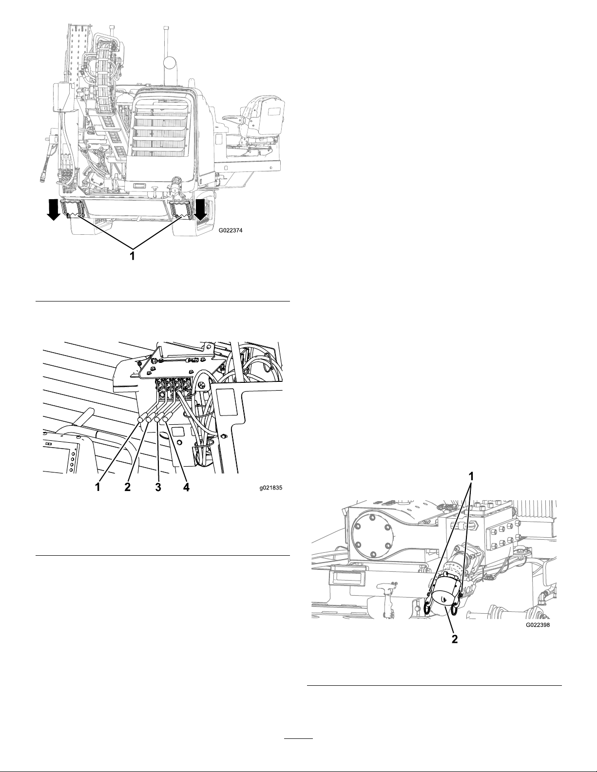
Figure79
g021835
1
2
3 4
1.Rearstabilizers
11.Pressthe2rightstakeleversintolowerandspinthe
rightstakeaugeruntilitseatsfully(Figure80).
ConnectingtoaDrilling-uidSource
Whendrillingandreaming,youpumpamixtureofbentonite
clay,water,andsometimesotheringredients,collectively
calleddrillinguidor“Mud”,throughthepipeandintothe
bore.Thisdrillinguid,or“Mud”,doesthefollowingfor
yourbore:
•Lubricatesthedrillhead
•Loosensthesoilintowhichthedrilliscutting
•Penetratesandbindsloosesoiltokeepthemfrom
collapsingontheborepipe.
Thespecicmixtureyouneedwillvarydependingonyour
soiltypeandtheoperationyouareperforming;refertoyour
mixingsystemOperator’sManualfordetails.
Conversely,forsomejobs(dependingonthesoiltypeand
distance),youcanpumpscreenedwaterfromanaturalwater
source,suchasalakeorriver,throughthedrillinlieuof
mixeddrillinguid.
•Toconnectthemachinetoamixingsystem,referto
SettingUptheMixingSystem(page61)
•Toconnectthemachinetoanaturalwatersource,referto
SettingUpthePumptoUseaNaturalWaterSource(page
62)
SettingUptheMixingSystem
Figure80
1.Left-stake-raise/lower
lever
2.Left-stake-spinlever
3.Right-stake-raise/lower
lever
4.Right-stake-spinlever
12.Repeatstep11fortheleft-sidestake.
Setupyourmixingsystemnearthedirectionaldrilllocation,
preferablydownwindsofumesfromthemixingsystem
enginewillnotbotheryouwhiledrilling.Followthe
instructionsprovidedinthemixingsystemOperator’ sManual
forsettingitupandusingit.
Completethefollowingtoconnecttheexithosefromthe
mixingsystemtothedrilling-uidpumponthemachine:
1.Raisethecam-lockleversonthepump-inletcapand
removethecap(Figure81).
Figure81
1.Cam-locklevers
2.Pump-inletcap
2.Insertthehosefromthemixingsystemoverthepump
inletandsecureitwiththecam-locklevers.
61
Page 62
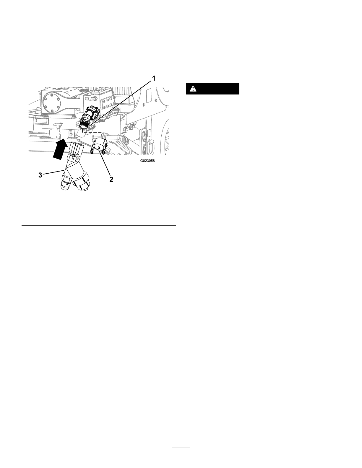
SettingUpthePumptoUseaNaturalWaterSource
DeployingtheZap-AlertSystem
Tosetupapumptouseanaturalwatersource,youmust
ensurethatyouusetheY-screentolterallmaterialsother
thanwater.
ToinstalltheY -screenperformthefollowingtasks:
1.Removethepump-inletcap(Figure82).
Figure82
TheZap-Alertsystemisanelectricstrikesensingdeviceon
themachinethattriggersastrobelightandaudiblealarmin
theeventthatthedrillbit,reamer,orstakebreaksintoan
energizedpowerline.Intheeventofanelectricstrike,the
machinewillbecomeenergized,settingoffthealarm.The
operator’splatformiselectricallyisolatedfromtherestof
themachinetoprotectyou.
DANGER
IftheZap-Alertsystemactivateswhiledrilling,the
machine,exceptfortheoperator’splatform,will
becomeenergized.Ifyoustepofftheoperator
platformorifsomeonetouchesthemachineorwet
groundnearthemachineorinthebore,youor
theycouldbeelectrocutedcausingseriousinjury
ordeath.
•TesttheZap-Alertsystembeforedrilling.
•Deploythegroundingstakebeforedrilling.
Ensurethatthestakeisfullyinsertedintomoist
soil.
•IftheZap-Alertistriggered:
1.Pumpthreads3.Y-screen
2.Pump-inletcap
2.AligntheY-screenwiththethreadsonthepump
(Figure82).
3.RotateandtightentheY -screenontothepump.
4.AttachthehosetotheY-screen,andbeginpumping
fromthenaturalwatersource.
–Stayintheseatanddonottouchtheground
oranyotherpartofthemachineuntilthe
powerhasbeenturnedoff.Donotpour
liquidsorurinatefromtheoperatorplatform
ontotheground.
–Stopdrilling,stopthedrilling-uidow,and
retractthedrilloutoftheground.
–Keepeveryoneawayfromthemachine,
wetgroundnearthemachineorrunning
fromthemachine,andanyopensourcesof
water/mudthatisintheboreandcontacting
thebrokenline.
–Contacttheutilitycompanytohavepower
shutofftothebrokenline.Donotresetthe
Zap-Alertsystemuntilthepowerhasbeen
turnedoff.
1.Removethegroundingstakefromtheholderonthe
sideoftheoperatorplatform(Figure83).
62
Page 63
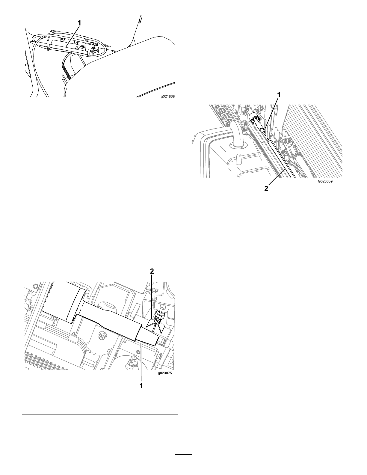
g021838
1
Figure83
1.Groundingstake
2.Movethestakedirectlyawayfromthemachine,
perpendiculartothedrillframeanddriveitintothe
grounduntilthehandletouchestheground.
3.Ifthegroundisdrywhereyouputthestake,soakit
withwaterbeforeusingthemachinetoensuregood
electricalcontact.
4.Lowerthepipeelevatorstoloadapipeintothepipe
gripper.
5.Rotatethepipegripperwiththepipetowardthedrill
frame,andextendthepipeuntilthepipeiscentered
overtheframeandinfrontofthespindleonthedrill
carriage.
6.Rotatethedrillspindleclockwiseandmovethecarriage
slowlyforwardtoinsertthespindleintothefemaleend
ofthepipe(Figure85).
DrillingtheBore
StartingtheFirstPipe
1.Ensurethatallbystandersareawayfromthemachine
andthattheexit-sidelockoutisOn.
2.Movethedrillcarriagefullydownthedrillframeand
spraythespindlethreadswiththreadjointcompound,
thenreturnthedrillcarriagetotheupperendofthe
frame(Figure83).
Figure85
1.Drillspindle2.Pipe
7.Continuetomovethedrillcarriageslowlydownthe
frameuntilthemalethreadsonthepipeareunder
thethread-joint-compoundapplicatorandapply
thread-jointcompoundtothethreads.
8.Releaseandretractthepipegripper,rotatingitallthe
wayouttothethirdrowofpipes.
Important:Ensurethatyoufullyretractthe
pipegripperandrotateitallthewayoutorthe
carriagemaycollidewiththegripper,damaging
themachine.
9.Continuetorotatethedrivespindleclockwise,until
themalepipethreadsarefullyseatedintothesonde
housingortheleadbar.
Note:Torquethethreadsto2305N-m(1700ft-lb).
Figure84
1.Drillspindle
2.TJC-applicatornozzle
3.Rotatethepipegrippertotherstrowofpipesin
thepipeholderbyaligningtherowindicatortorow
number1.
63
Page 64
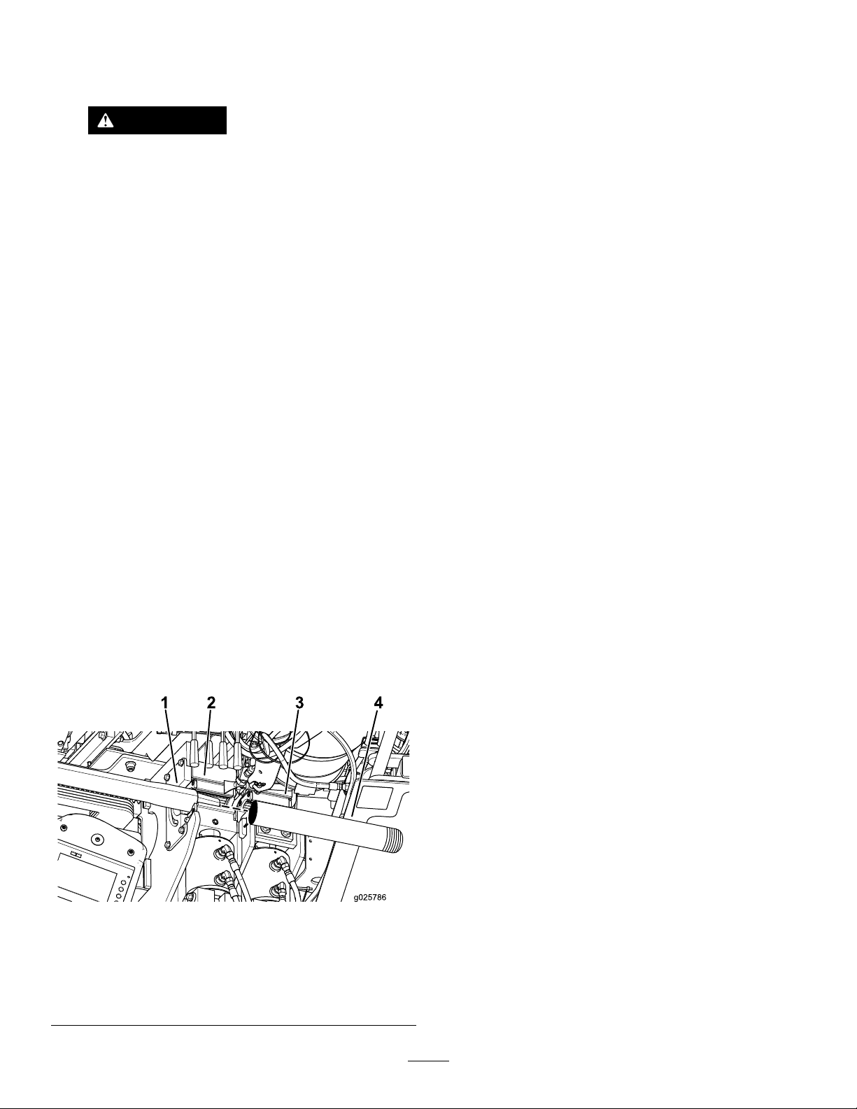
InstallingtheDrillHead
1.Usingtheexit-side-lockouttransmitter,enabletheexit
sidelockout.
WARNING
Ifthedrillrotatesorextendswhileyouor
othersaremanuallyworkingonthedrillbitor
pipeinfrontofthemachine,theworkercould
getcaughtinthebitorpipecausingserious
injury,amputation,ordeath.
•Enabletheexit-sidelockoutonthe
exit-side-lockouttransmitterbefore
approachingthedillbitorpipewhen
attachedtothemachine.Thiswilldisable
thedrillcarriage.
•Donotwearlooseclothingorjewelrywhen
workingonadrillbitorpipeattachedto
themachine.Tielonghairupandoutof
theway.
5.Usingtheupperwrench,clamptheleadbarandtighten
ittofullmachinetorque.
6.Usingtheexit-side-lockouttransmitter,enablethe
exit-sidelockout.
7.Doublecheckthedrillheadandbittoensurethatthe
uidportsarecleanandfreefromobstructions.
8.Installthedrillheadontotheendoftheleadbaras
directedbythedrillheadmanufacturer,thenclearaway
fromthefrontofthemachine.
Important:Donotpullthedrillheadintothe
pipeguideoryoumaydamagethemachineorthe
drillhead.
BoringtheEntryShaft
Therstboringstepistocreatetheentryshaft.Inthisstep,
youpushandborethedrillbitandrstfewpipesintothe
groundatananglefrom0to16degrees(withthetracksat
ontheground)untilyoureachthedesireddepthofyour
installation.
2.Handthreadtheleadbarontothepipethreadsthen
clearawayfromthefrontofthemachine.
3.Whentheareaisclearofpeople,disabletheexit-side
lockoutusingtheexit-side-lockouttransmitter
(theOK-to-Drilllightonthecontrolpanelshould
illuminate);presstheexit-side-lockout,resetswitchon
thecontrolpanel.
4.Pullthedrillpipeandleadbarbackthroughthepipe
guideandintothewrenches,aligningthethickened
upperjointoftheleadbarwiththeupperwrench
(Figure86).
Important:Donotclampthewrenchonthebody
ofapipeoritmaydamagethepipe.Gripthepipes
onthethickenedareanearthejoint.
Important:Drillandreaminaclockwiserotation.
Ifyouuseacounterclockwiserotationthepipewill
disconnectfromeachotherandmaybedisconnected
underground.
1.Whentheareaisclearofpeople,disabletheexit-side
lockoutusingtheexit-side-lockouttransmitter
(theOK-to-Drilllightonthecontrolpanelshould
illuminate);presstheexit-side-lockout,resetswitchon
thecontrolpanel.
2.Turnonthedrillinguidpumpswitchandallowthe
uidpressuretobuildto200to300psi.
3.Rotatethedrillheaduntilthebitisatthe6o’clock
position.
4.Movethecarriageforwarddrivingthebitstraightinto
thegrounduntiltheentiredillhousingisunderground.
5.Continuepushingforwardandbeginrotatingthedrill
spindleclockwisetoinitiatethedrillingaction.
6.Drillforwarduntilthecarriagereachestheendofthe
frame,thenretractitabout6mm(1/4inch).
AddingDrillPipes
1.Drillpipe
2.Upperwrench
1.Alignthepipejointinthewrenchassembly.
2.Closethelowerwrench(stationarywrench)ontothe
rstpipe.
Figure86
3.Lowerwrench(stationary
wrench)
4.Leadbar
(makeup/breakout
wrench)
64
Note:Thedrillinguidwillautomaticallyshutoff
whenyouactivatetheupperwrench(makeup/breakout
wrench).
3.Pullbackthecarriageapproximately12.7mm(0.5
inch).
Page 65
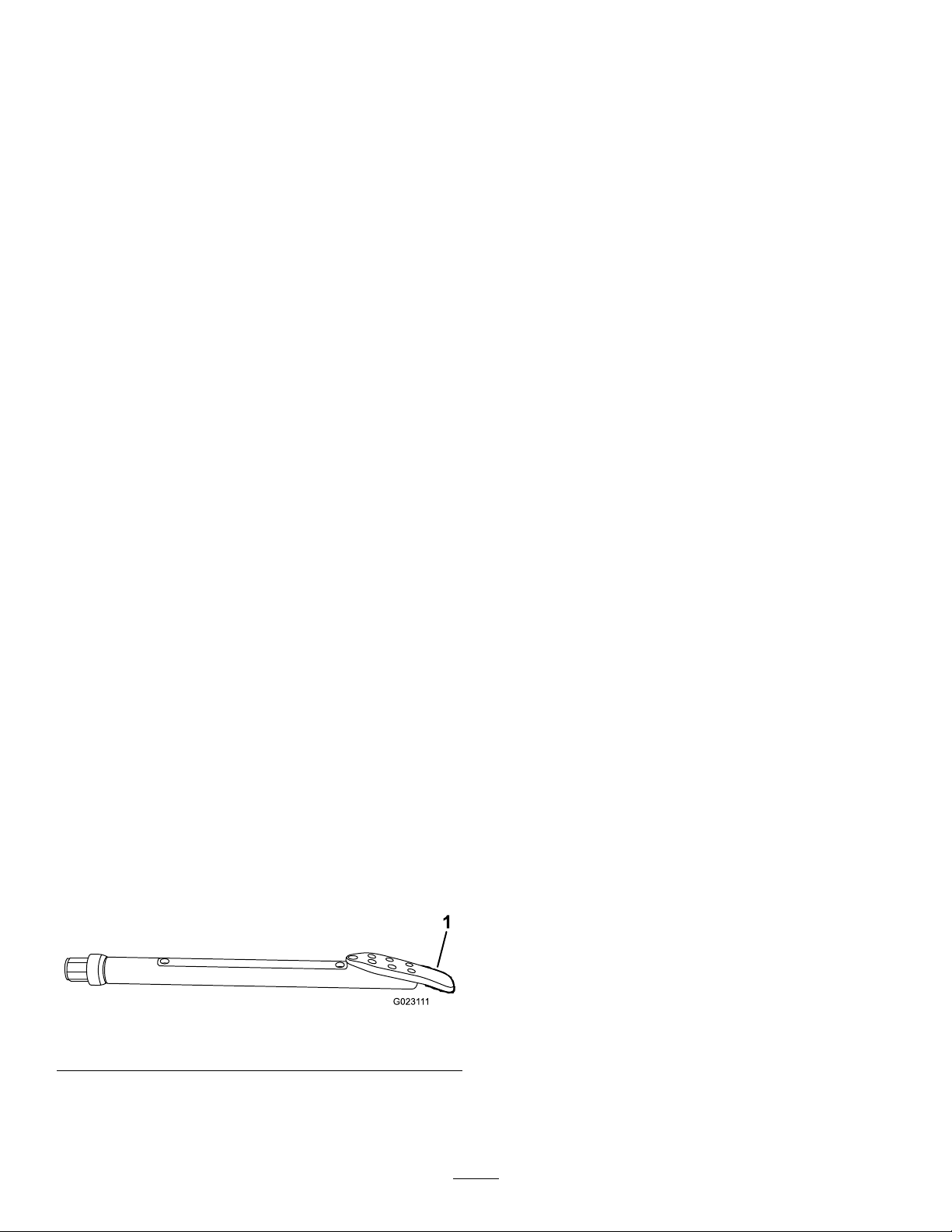
Note:Thiswillallowthecarriagetooat,andwillnot
damagethepipethreads.
4.Rotatethedrillheadcounterclockwiseuntilthespindle
iscompletelyremovedfromthepipe.
5.Spraythespindlewiththreadjointcompound,then
returnthedrillcarriagetotheupperendoftheframe.
6.Rotatethepipegrippertotheclosestrowofpipesin
thepipeholder.
7.Lowerapipeintothepipegripperandgripitinplace.
8.Rotatethepipegrippertowardthethrustframe,and
extendituntilthepipeiscenteredovertheframeand
infrontofthespindleonthedrillcarriage.
9.Rotatethedrillspindleclockwiseandmovethecarriage
slowlyforwardtoinsertthespindleintothefemaleend
ofthepipe(Figure85).
Note:Tightenthejointuntilthepipeisrotatingwith
thespindle.
10.Movethedrillcarriageslowlydowntheframe
untilthemalethreadsonthepipeareunder
thethread-joint-compoundapplicatorandapply
thread-jointcompoundtothethreads.
11.Rotatethedrillspindleclockwiseandmovethecarriage
slowlyforwardtoinsertthemaleendofthepipeinto
thefemaleendofthepreviouspipe.Tightenthejoint
untilyoureachnomorethan2,304N-m(1,700ft-lb).
12.Releaseandretractthepipegripper,rotatingitallthe
wayoutpastthethirdrowofpipes.
transmittertemperature,andorientationinthesoil.The
remoteconsoleisascreenthatremainsnearyou(thedrill
operator)toshowyoutheinformationfromthereceiver
whiledrillingsoyoucanmakesteeringdecisions.
Fordetailedinformationonusingthereceiverandremote
consoletoguidethedrillhead,refertotheOperator’ sManual
thatcamewithyourreceiver.
Important:Donotsteerthedrillheadmorethan20cm
(8inches)offcenterforevery10feetofforwardtravel.If
yousteermorethanthisyouwilldamagethedrillpipes.
BoringtheHorizontalShaft
Aftercreatingtheentryshaft,yougraduallysteerthedrill
headupwhilepushingforward,followingtheplannedbore
path.Whenyoureachthedesireddepth,leveloutthedrill
headandborethehorizontalshaft,addingpipesasyougo.
Whileboring,paycloseattentiontotheinformationrelayed
backtoyoubythereceiveroperatoraboutthestatusand
locationofthedrillheadtoensurethatyouarefollowingthe
plannedpath.
Important:Whiledrilling,watchthesondetemperature.
Allsondeshaveamaximumtemperatureabovewhich
theywillbedamaged.Frictionbetweenthedrillhead
andthesoilwillcausethetemperaturetoraise.To
reducethetemperature,slowdown,decreaseforward
pressure,andincreasethedrillinguidow.Ifthedrill
headisenteringasoiltypeotherthanwhatitisdesigned
for,thatcanalsoraisetemperature.Assessthesituation
andpulloutthedrillheadandchangeitifnecessary.
Important:Ensurethatyoufullyretractthe
pipegripperandrotateitallthewayoutorthe
carriagemaycollidewiththegripper,damaging
themachine.
13.Releasethewrenchandcontinuethedrillingoperation.
SteeringtheDrillHead
Thedrillbitisshapedlikeawedge,angledfromonesideof
thebittotheother.Whenyoupushthebitthroughthesoil
withoutrotatingit,itwillveertowardthedirectionthewedge
ispointing.Whenyourotatethepipeanddrillheaditbores
throughthesoilinastraightpath.
Figure87
1.Drillbit
Whendrilling,thereceiveroperatorfollowsthedrillheadasit
progresses.Thereceiverreceivessignalsfromthesondein
thedrillheadidentifyingitsposition,depth,pitch,direction,
Ifyourunintoanobstruction,dothefollowing:
1.Increasetheowofthedrillinguidforafewseconds
withoutdrilling,thenattempttocontinuedrilling
forward.
Thismayloosentheobstructionandallowyoutopush
pastit.
2.Iftheobstructionpersists,tryoneormoreofthe
followingoptions:
•Iftheobstructionisinanareawhereyoucandig,
stopthedrillheadwiththeExitSideLockout
anddigdowntotheobstructiontoidentifyitand
removeitifpossible.
•Pullthedrillheadback15m(50ft)ormoreand
steerthedrillheadtotheside,markinganewdrill
patharoundtheobstacle.
Important:Donotsteerthedrillheadmore
than20cm(8inches)offcenterforevery10
feetofforwardtravel.Ifyousteermorethan
thisyouwilldamagethedrillpipes.
•Iftheobstructionisactuallyachangeinsoiltypes,
suchasazoneofrockysoil,pullthedrillheadall
thewaybackandchangetoadrillbitappropriate
fordrillingthroughthenewsoiltype.
65
Page 66

ExitingtheGround
BackreamingandPullback
Asyouapproachtheendofthebore,steerthedrillheadto
theexitpoint,keepingthesteeringlimitsinmindasyoudo
so.Beforeexitingtheground,ensurethateveryoneisaway
fromtheexitpoint.Assoonasyoubreakthrough,stopthe
drilling-uidow .Extendthedrillforwarduntiltheentire
drillheadisoutoftheground.
Afterdrillingtheinitialbore,youattachareamertothepipe
whichisthenconnectedtoatheproductyouareinstalling.
Thereamerisdesignedtowidenthebore,packthewallsand
lubricatethepassageoftheproductintothebore.
ThefollowingreamersareavailablefromyourAuthorized
ToroDealerinvarioussizestomeetyourneedsandsoil
conditions:
•Carbidestep-wingcutter—Usethisreamerinsandy
andmediumclaysoilconditionstomixthedrillinguid
withthesoil,makingamixturethatowseasilyaround
theproductbeingpulled.
•Castconepacker—Usethisreamerinsoilsthatpack
easily,suchassoftclay,peat,andloam,topackthesides
ofthebore,maintainingtheboreopening.
•Flutedreamer—Usethisreamerinhardclayandrocky
soils;itcombinesthefeaturesoftheothertworeamers.
ConnectingtheReamerandProduct
WARNING
Ifthedrillrotatesorextendswhileyouorothersare
manuallyworkingonthedrillbitorpipeinfrontof
themachine,theworkercouldgetcaughtinthebit
orpipecausingseriousinjury,amputation,ordeath.
•Enabletheexit-sidelockoutonthe
exit-side-lockouttransmitterbeforeapproaching
thedillbitorpipewhenattachedtothemachine.
Thiswilldisablethedrillcarriage.
•Donotwearlooseclothingorjewelrywhen
workingonadrillbitorpipeattachedtothe
machine.Tielonghairupandoutoftheway .
1.Usingtheexit-side-lockouttransmitter,enabletheexit
sidelockout.
2.Removethedrillheadfromtheleadbar.
3.Doublecheckthereamertoensurethattheuidports
arecleanandfreefromobstructions.
4.Installthereamerandswivelontotheendofthelead
barasdirectedbythereamermanufacturer
5.Connecttheproducttothereamerusinganappropriate
pullingconnection;refertoyourAuthorizedToro
Dealertoacquiretheappropriatepullertomeetyour
requirements.
66
Page 67
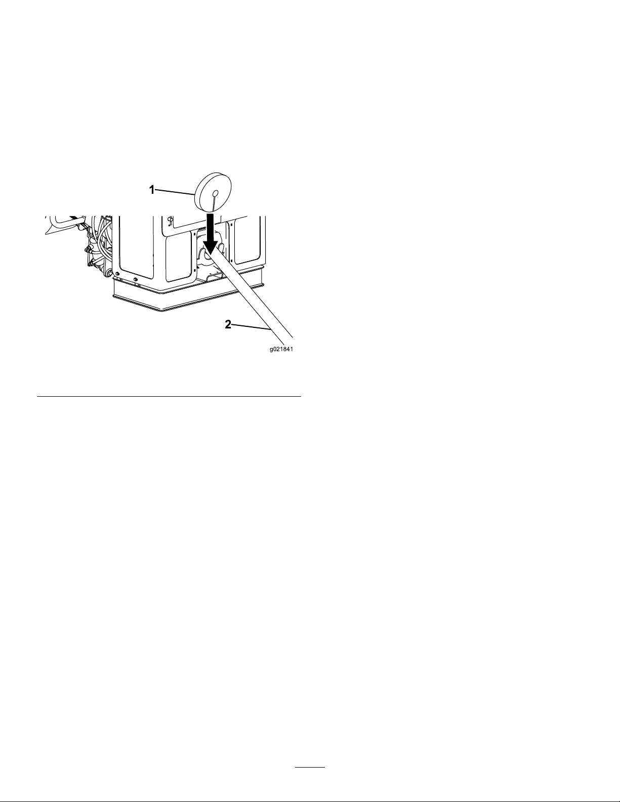
RemovingDrillPipes
g021841
1
2
1.Usingtheexit-side-lockouttransmitter,enabletheexit
sidelockout.
2.Installadrill-pipewiperaroundthepipeandintothe
retainingbracketonthefrontofthemachine.
Thiswillremovemostofthedirtandmudfromthe
pipeasyoupullitbackintothemachine,keepingthe
machineclean.ContactyourAuthorizedToroDealer
topurchasedrill-pipewipers.
13.Movethedrillcarriagebackuntilthemale-pipethreads
justclearthefemaleendofthelowerpipe,thenclose
theupperwrenchontothepipeend,butnotonthe
threads.
14.Rotatethedrillspindlecounterclockwiseuntilthe
upper-pipejointisloosebutnotseparated.
15.Releasetheupperwrench.
16.Movethedrillcarriagebackuntilthepipeislinedup
withthepipeholder.
17.Rotatethedrillspindlecounterclockwisemoving
rearwardslowlyuntilthespindlefullyseparatesfrom
thepipe.
18.Retractthepipegripperarms.
19.Rotatethepipecamtothedesiredrow.
Note:Filltheoutsiderowsrst.
20.Releasethepipegripperandraisethepipeintothe
holderrow .
21.Raisethepipeintothepipebasketwiththepipe
elevators.
22.Rotatethepipegripperpastthethirdrowofpipes.
Figure88
1.Drill-pipewiper2.Drillpipe
3.Disengagetheexit-sidelockoutandresetthesystem.
4.Beginrotatingthedrillspindleclockwiseandslowly
retractthedrillcarriagetopullthepipebackintothe
machine
5.Whenthejointbetweenthepipesiscenteredbetween
thetwowrenches,thedrillcarriagewillstop,anda
greenlightwillilluminatebelowthesprayvalve.
6.Closethelowerwrenchontothepipejoint.
Note:Thedrillinguidwillautomaticallyshutoff
whenyouclosethelowerwrench.
7.Rotatethepipegrippertothedrillframe,extendthe
pipe-gripperarmstothepipe,andgripthepipeto
supportit.
8.Closetheupperwrenchontothepipejoint.
9.Rotatetheupperwrenchcounterclockwiseuntilthe
jointisloosened.
10.Releasetheupperwrench.
11.Pullbackthecarriageapproximately12.7mm(0.5
inch).
Important:Ensurethatyoufullyretractthe
pipegripperandrotateitallthewayoutorthe
carriagemaycollidewiththegripper,damaging
themachine.
23.Movethedrillspindledowntheframeunderthe
thread-joint-compoundapplicator,andspraythe
spindlewiththreadjointcompound.
24.Rotatethedrillspindleclockwiseandmovethecarriage
slowlyforwardtoinsertthespindleintothefemaleend
ofthepipesecuredinthelowerwrench.
Note:Tightenthejointuntilyoureachnomorethan
2,304N-m(1,700ft-lb).
25.Releasethewrenchandcontinuereaming/retraction
asneeded.
RemovingtheLastPipeandtheReamer
Important:Donotpullthedrillheadintothepipe
guideoryoumaydamagethemachineorthedrillhead.
1.Usingtheexit-side-lockouttransmitter,enabletheexit
sidelockout.
2.Afterthereamerhasclearedtheground,ifyouhave
notalreadydoneso,disconnecttheproductbeing
installedfromthereamer.
3.Connectthedrillinguidpumptoasourceofclean
water.
Note:Thiswillallowthecarriagetooat,andwillnot
damagethepipethreads.
12.Rotatethedrillspindlecounterclockwisemoving
rearwardslowlyuntilthepipesareseparated.
4.Turnthepumpontoushcleanwaterthroughthe
pump,spindle,andreameruntilthewaterrunsclear.
5.Removeandstorethelastpipe;refertoRemovingDrill
Pipes(page67).
67
Page 68
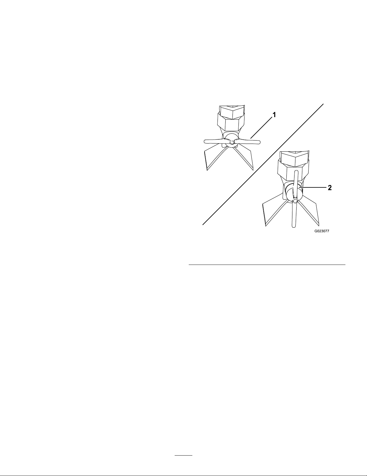
6.Leavetheleadbarclampedinthelowerwrench,butdo
notconnectthedrillspindletotheleadbar.
UsingtheTJCApplicator
7.Removethereamerfromtheendoftheleadbaras
directedbythereamermanufacturer.
8.Releasethelowerwrenchandpulltheleadbaroutof
thepipeguide.
FinishingtheJob
Completethefollowingaftereachdayofuse:
•Connectthehandsprayguntothepumpandcleanthe
machinewithcleanwater;refertoCleaningwiththe
Spray-hoseAttachment(page102).
•Addgreasetothegreasettings;refertoGreasingthe
Machine(page75).
•Iftheairtemperatureisbelowfreezingorwillbebefore
thenextuse,refertoPreparingtheDrilling-uidSystem
forColdWeather(page101).
•Installthecontrolscovers;refertoOperator-Controls
Covers(page21).
•Flushthedrillinguidoutofthedrilling-uidpumpwith
waterorantifreeze.
AdjustingtheApplicatorNozzle
Youcanadjusttheapplicatornozzletospraythread-joint
compound(TJC)eitherinafan-shapedsprayorasastream.
•Forfan-shapedspray—turnthesprayvalveontheside
ofthenozzlehorizontal(Figure89).
•Forastream—turnthesprayvalveonthesideofthe
nozzlevertical(Figure89).
Note:Thedrilling-uidpumpmaybedamagedifthe
drilling-uiddriesupinthepump.
Figure89
1.Sprayvalve—fan-shaped
spray(horizontal)
2.Sprayvalve—stream
(vertical)
68
Page 69
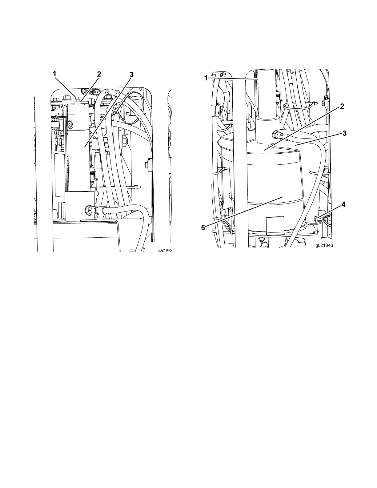
AdjustingtheTJC-sprayVolume
g021845
1
2
3
g021846
1
2
3
5
4
FillingtheTJCApplicator
Toadjustthevolumeofthread-jointcompoundthatis
deliveredbytheapplicator,completethefollowing:
1.Loosenthejamnutontheadjustmentboltlocatedon
topoftheTJC-applicatorpiston(Figure90).
1.Stopthemachineandstoptheengine.
2.Openthestake-down-guarddoor.
3.Loosenthewingnutssecuringthecoverstrapstothe
machine(Figure91).
Figure90
1.Adjustmentbolt
2.Jamnut
3.TJC-applicatorpiston
2.Adjusttheboltasfollows:
•Toincreasetheappliedvolumeofcompound,
threadtheboltout(up).
•Todecreasetheappliedvolumeofcompound,
threadtheboltin(down).
3.Whenyouhaveattainedthedesiredapplicationvolume,
tightenthejamnuttosecuretheadjustment.
1.TJC-applicatorpiston
2.Cover5.TJCbucket
3.Strap
4.Rotatethecoverandpullthecoverstrapsoffthe
retainingbolts(Figure91).
5.Liftthecoverassemblyoffandoutoftheempty
thread-joint-compoundbucket(Figure91).
6.Replacetheemptybucketwithanewfullbucket.
7.Placetheplungerintothenewbucketandlowerthe
coverassemblyontothebucket(Figure91).
Figure91
4.Wingnut
8.Slidethecoverstrapsovertheretainingboltsandrotate
thecovertoseatthestrapsonthebolts(Figure91).
9.Tightenthewingnuts.
69
Page 70
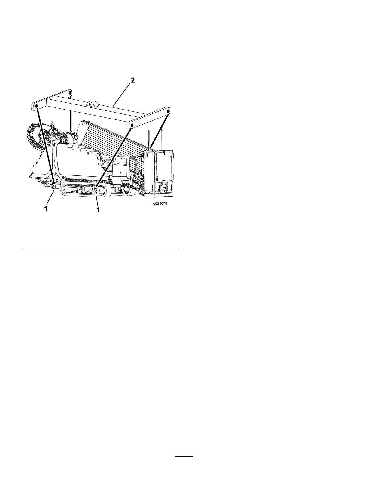
MovingaDisabledMachine
Wheneverthemachineisstoppedandtheengineisnot
running,thehydrostaticbrakesautomaticallyengage.Donot
attempttotowthemachineifitcannotmoveunderitsown
power.Ifpossible,repairthemachineatthesite.Ifthisisnot
possible,useacraneandaspreaderbartoliftthemachine
ontoatrailer,usingtheliftpointsshowninFigure92.
Figure92
Repeatliftpointsonotherside
1.Spreaderbar2.Liftpoint
70
Page 71

Maintenance
Note:Determinetheleftandrightsidesofthemachinefromthenormaloperatingposition.
RecommendedMaintenanceSchedule(s)
MaintenanceService
Interval
Aftertherst100hours
Aftertherst250hours
Beforeeachuseordaily
Every50hours
Every250hours
MaintenanceProcedure
•Checkthegearboxdriveoil.
•Changethegearbox-driveoil.
•Adjustthevalveclearance.
•Changetheplanetaryoil.
•Checkthefuellevel.
•Greasethemachine.(Greaseimmediatelyaftereverywashing).
•Checkthecrankcase-venttubeandcleanitifnecessary.
•Checktheindicatoronthedisplayscreenforarestrictedairlter.
•Checktheengine-oillevel.
•Checkthetracktension.
•Checkthecoolantlevelinthereservoirfortheradiator.
•Checkthehydraulicuidlevel.
•Checkthedrilling-uid-pumpoillevel.
•Cleanthemachinewiththespray-hoseattachment.
•Checkandcleanthedustvalve.
•Removeaircleanercoverandcleanoutdebris.Donotremovethelter.
•Checkthefuel-waterseparatorforwaterandsediment.
•Checkthebatterycondition
•Checktheplanetary-driveoillevel(Also,checkifexternalleakageisobserved).
•Checkthecoolantlevelintheradiator.
•Cleanorreplacetheair-cleanerlter.
•Changetheengine-oillter.
•Changetheengineoil.
•Clearthesparkarrestorinthemuferofcarbonbuildup.
•Replacetheprimaryandsecondary,fuellters.
•Checktheconditionoftheengine-drivebelt.
Every300hours
Every500hours
Every800hours
Every1,000hours
Every2,000hours
Yearlyorbeforestorage
Every2years
Important:Refertoyour
•Checktheconditionofthecoolantsystemcomponents.Cleandirtanddebrisfrom
themandrepairorreplacethecomponentsasnecessary.
•Inspectthefuellinesandconnections.
•Checkthegearboxdriveoil(oryearly,whichevercomesrst).
•Changethegearbox-driveoil(oryearly,whichevercomesrst).
•Changethehydraulic-uidreturnlter.
•Changethehydraulic-pressurelter.
•Changethedrilling-uidpumpoil.
•Changetheplanetaryoil(oryearly,whichevercomesrst).
•Drainandcleanthefueltank.
•Checktheconcentrationofthecoolantbeforethewinterseason.
•Cleanthecoolingsystem.(Cleanthecoolingsystemifthecoolantbecomesdirtyor
rustcolored.)
•Checkthetensionontheenginedrivebelt.
•Changethehydraulicuid.
•Adjustthevalveclearance.
•Touchupchippedpaint.
•Replacemovinghoses.
Engine Operator's Man ual
foradditionalmaintenanceprocedures.
71
Page 72
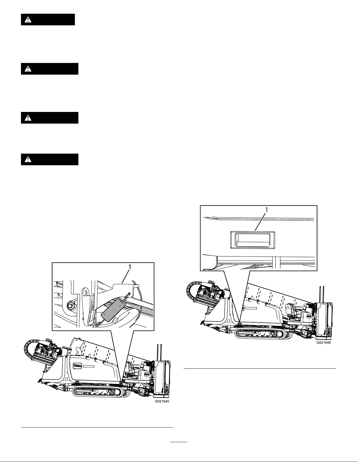
CAUTION
Ifyouleavethekeyintheignitionswitch,someonecouldaccidentlystarttheengineandseriouslyinjure
youorotherbystanders.
Removethekeyfromtheignitionbeforeyoudoanymaintenance.
WARNING
Improperlyservicingorrepairingthemachinemaycauseinjuryordeath.
Ifyoudonotunderstandtheserviceproceduresforthismachine,contactyourdealerorseetheservice
manualforthismachine.
WARNING
Raisedequipmentonthemachinewithoutanoperatormaycauseinjuryordeath.
Beforeyouleavetheoperator’scompartment,supportorlowertheequipmentandstoptheengine.
WARNING
Replaceallcoversandguardsafteryouserviceorcleanthemachine.Donotoperatethemachinewithout
thecoversorguardsinplace.
Premaintenance
Procedures
OpeningtheFrontHood
1.Parkthemachineonalevelsurface,stoptheengine,
andremovetheignitionkey.
2.PushdownonthehoodlatchasshowninFigure93.
3.LiftuponthehandleasshowninFigure94.
Figure94
1.Hoodhandle
1.Hoodlatch
Figure93
72
Page 73
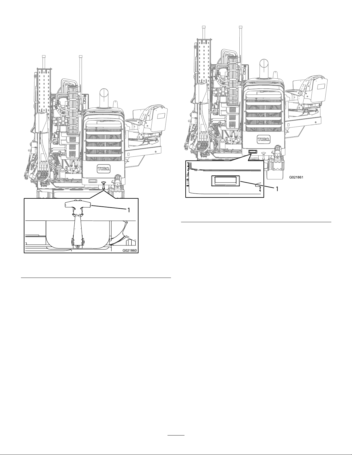
OpeningtheRearHood
1.Parkthemachineonalevelsurface,stoptheengine,
andremovetheignitionkey.
2.Pullthehoodlatchout(Figure95).
3.LiftupthehandleasshowninFigure96.
1.Hoodlatch
Figure96
1.Hoodhandle
Figure95
73
Page 74
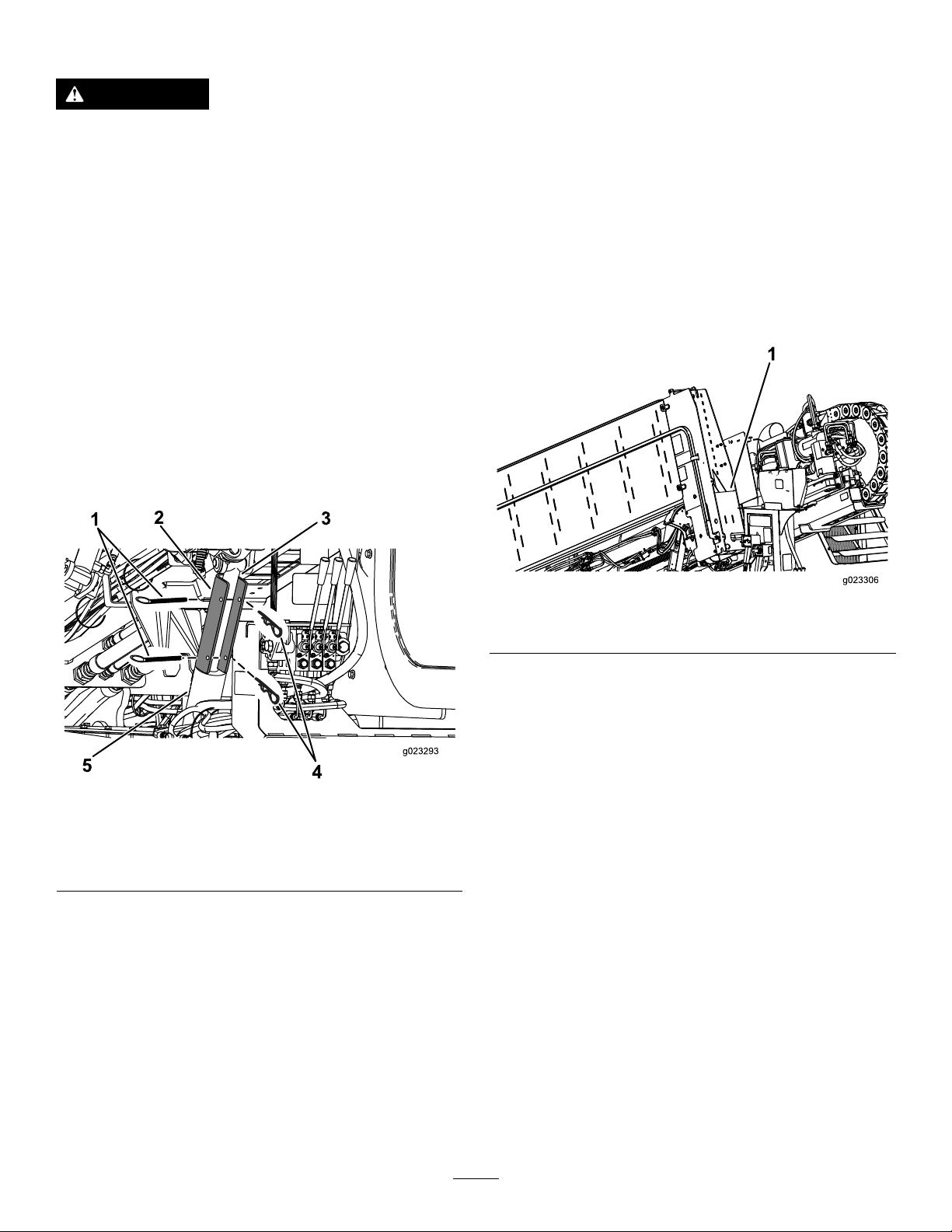
UsingtheCylinderLock
WARNING
Thethrustframemaylowerwhenitisintheraised
position,causingseriousinjuryordeath.
Installthecylinderlockbeforeperforming
maintenancethatrequiresthethrustframetobe
raised.
RemovingandStoringtheCylinder
Lock
1.Starttheengine.
2.Lowerthethrustframetothefullyloweredposition.
3.Stoptheengine.
4.Removethecotterpinandtheclevispinthatsecurethe
cylinderlock(Figure97).
5.Removethecylinderlock.
InstallingtheCylinderLock
1.Starttheengine.
2.Lowerthethrustframetothefully-loweredposition.
3.Stoptheengine.
4.Positionthecylinderlockoverthecylinderrod(Figure
97).
5.Securethecylinderlockwiththecotterpinandclevis
pin(Figure97).
6.TurntheenginetotheOnposition,andraisethethrust
frameuntilitrestsonthecylinderlock.
6.TurntheenginetotheOnposition,andraisethethrust
frame.
7.Storethecylinderlocknexttotheanti-freezetank
(Figure98).
Figure98
1.Locationbehindtherearofthepipeholder
Figure97
1.Cotterpin4.Clevispin
2.Cylinderlock5.Liftcylinder
3.Liftcylinderrod
74
Page 75
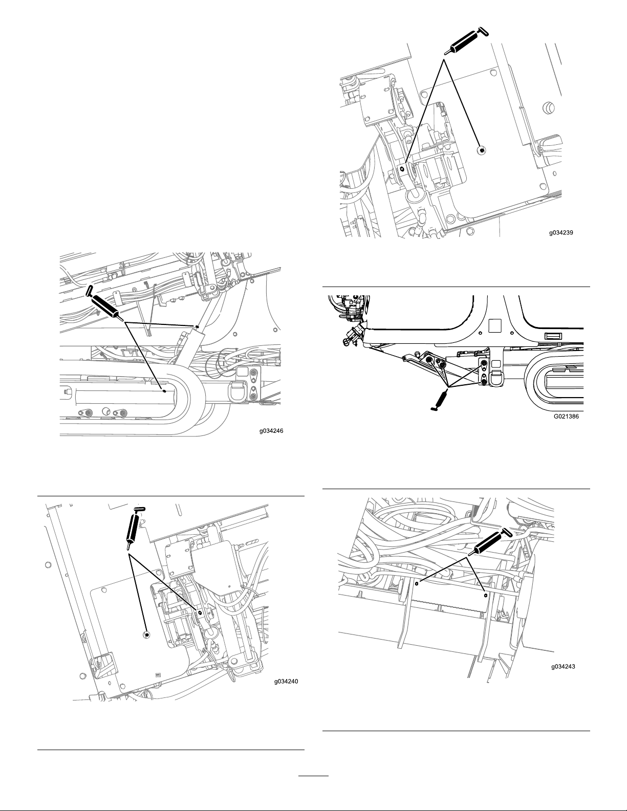
Lubrication
GreasingtheMachine
ServiceInterval:Beforeeachuseordaily(Grease
immediatelyaftereverywashing).
Greasetype:General-purposegrease.
1.Parkthemachineonalevelsurface,stoptheengine,
andremovetheignitionkey.
2.Cleanthegreasettingswitharag.
3.Connectagreaseguntoeachtting.
4.Pumpgreaseintothettingsuntilgreasebeginsto
oozeoutofthebearings(approximately3pumps).
5.Wipeupanyexcessgrease.
Figure99
Liftcylinder(drill/carriageside;lowergreasettingisbehind
thetrackroller)
Figure101
Rear-pipeelevatorandcamcylinder(drill/carriageside)
Figure102
Stabilizercylinderandfoot(drill/carriageside;repeaton
otherside)
Figure100
Front-pipeelevatorandcamcylinder(drill/carriageside)
Figure103
Thrust-framepivotpin(Undersideofmachine)
75
Page 76
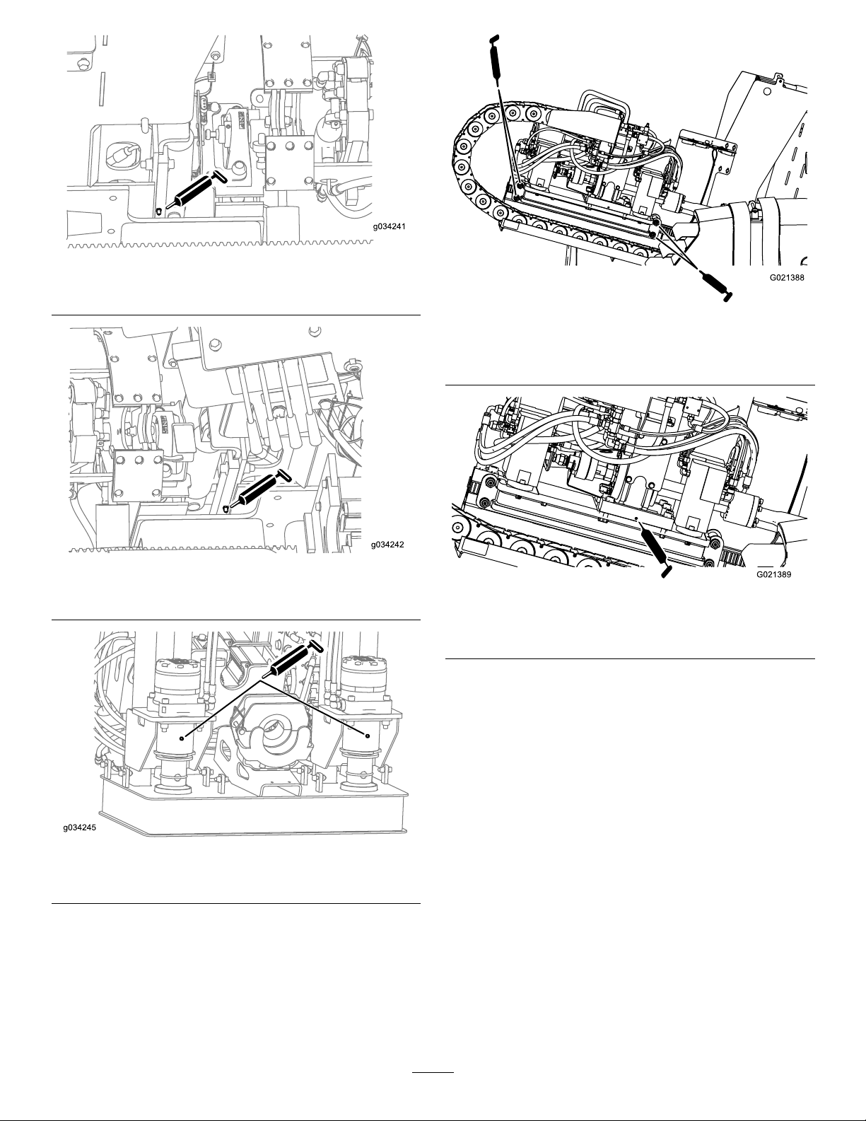
Figure104
Rear-pipeelevator(operator’sside)
Figure105
Front-pipeelevator(operator’sside)
Figure107
Carriage-rollerbearings(operator’ssideshown;repeaton
otherside)
Figure108
Gearboxoat(operator’ssideshown;repeatonotherside)
Stakedownmotors
Figure106
76
Page 77
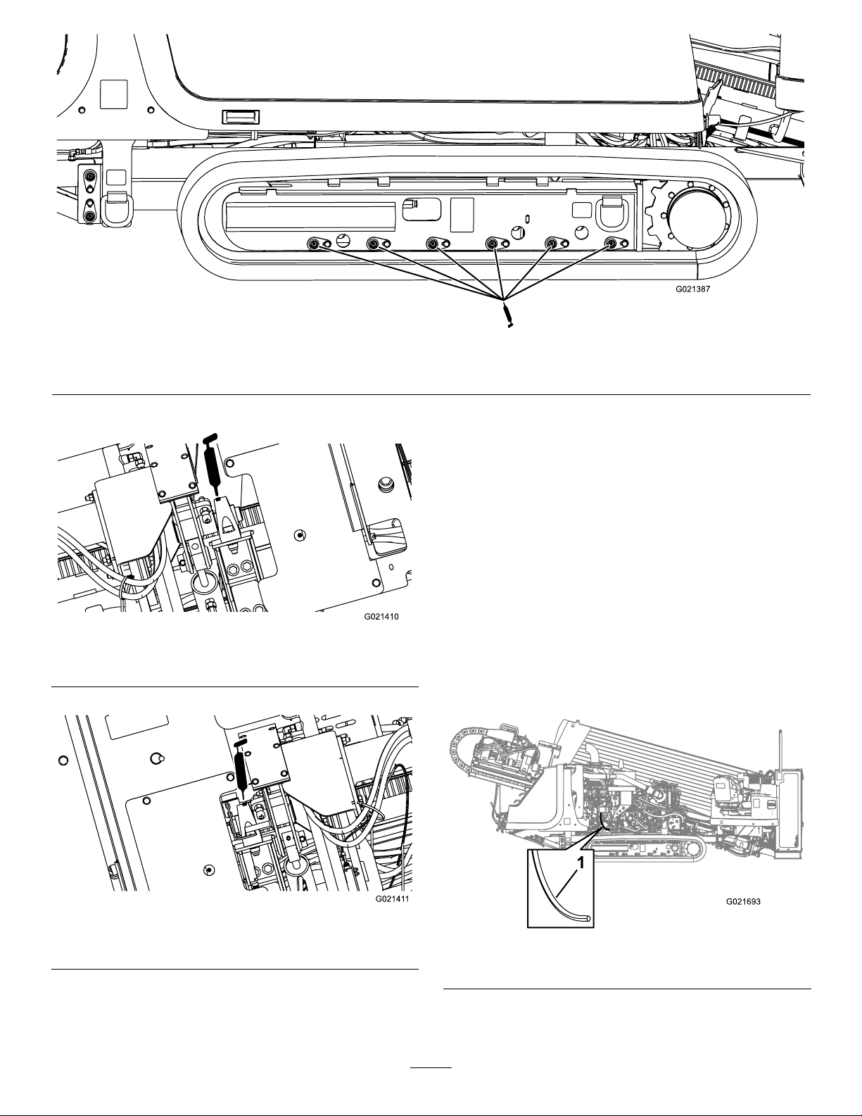
Figure109
Trackroller(operator’ssideshown;repeatonotherside)
EngineMaintenance
CleaningtheCrankcase-vent
Tube
ServiceInterval:Beforeeachuseordaily—Checkthe
1.Parkthemachineonalevelsurface,stoptheengine,
andremovetheignitionkey.
crankcase-venttubeandcleanitif
necessary.
Figure110
Rear-cambearing(operator’sside)
Figure111
Front-cambearing(drill/carriageside)
2.Openthefronthood;refertoOpeningtheFront
Hood(page72).
3.Gentlypullthecrankcase-venttubeout(Figure112).
4.Cleantheendofthecrankcase-venttube(Figure112).
Figure112
1.Crankcaseventtube
77
Page 78
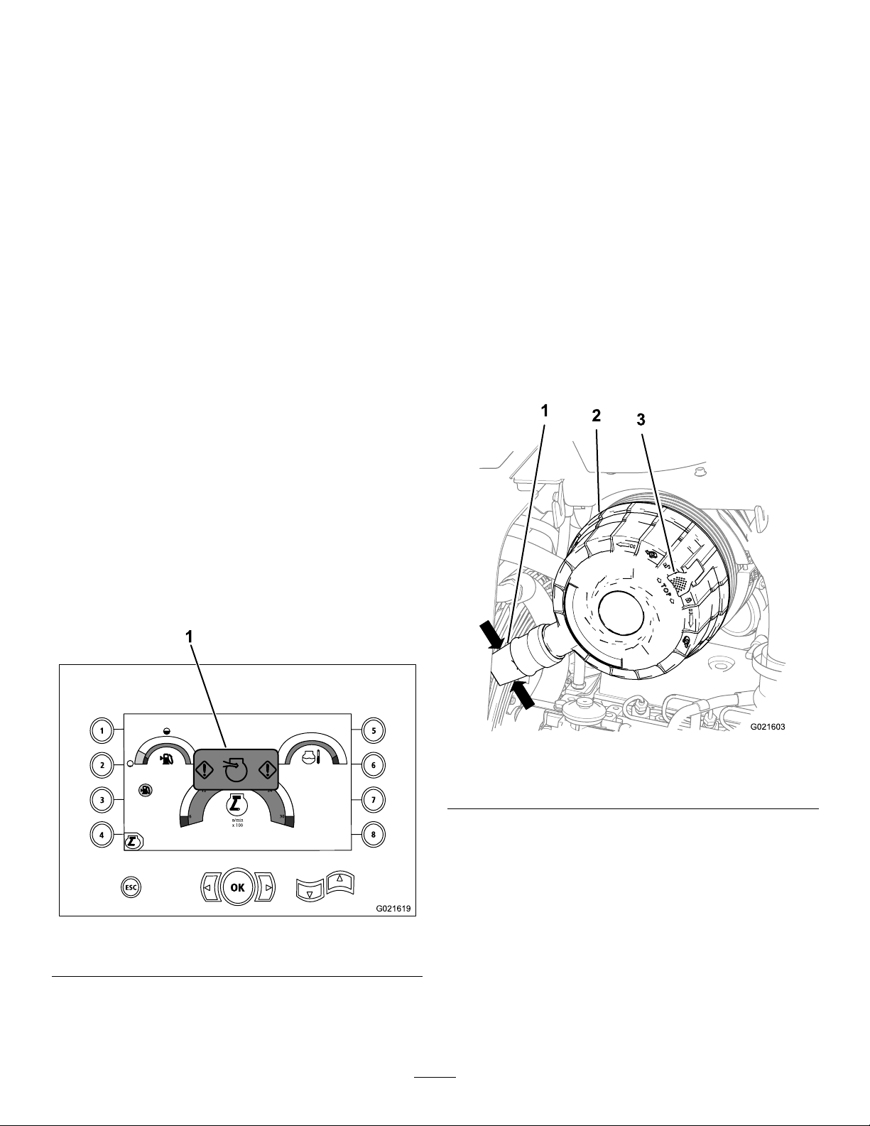
ServicingtheAir-cleaning
1
ESC
2
3
4
5
6
7
8
OK
6
12
18
24
30
n/min
x 100
G021619
1
System
Important:Donotremovetheelementsfromthe
machinetocheckfordirtylters;usethefollowing
procedureinstead.
Important:Donotreplacetheoldair-cleanerlterwith
alterthatismorethan5yearsold;checkthedateof
manufactureontheendcapoftheelement.
Note:Everytimeyouservicetheair-cleanersystem,ensure
thatallhoseconnectionsandangesareairtight.Replace
alldamagedparts.
•Checktheair-cleanerbodyfordamagewhichcouldcause
anairleak.Replaceitifitisdamaged.Checkthewhole
intakesystemforleaks,damageorloosehoseclamps.
Also,inspecttherubberintakehoseconnectionsatthe
aircleanerandturbotomakesuretheconnectionsare
complete.
•Servicetheair-cleanerlteronlywhen“CheckAirFilter”
isdisplayedonthescreen.Changingtheairlterbefore
itisnecessaryonlyincreasesthechanceofdirtentering
theenginewhenthelterisremoved.
•Besurethecoverisseatedcorrectlyandsealswiththe
air-cleanerbody .
B.Repeatsteps1and2;iftherestrictedair-cleaner
indicatorisstillshownonthedisplayscreen,
replacethesecondary,air-cleanerlter;referto
ServicingtheAir-cleanerFilter(page80).
CleaningtheDustValve
ServiceInterval:Every50hours
1.Parkthemachineonalevelsurface,stoptheengine,
andremovetheignitionkey.
2.Openthefronthood;refertoOpeningtheFront
Hood(page72).
3.Squeezethesidesofthedustvalveontheair-cleaner
covertoreleaseanycollectedwater,dust,ordirtfrom
thevalve.(Figure114).
Note:Ensurethattherearenoobstructionsinside
thedustvalve.
CheckingtheAir-cleanerIndicator
ServiceInterval:Beforeeachuseordaily
1.Starttheengine.
2.Checktherestricted,air-cleanerindicatoronthedisplay
screenasshowninFigure113.
Figure113
1.Restrictedair-cleanerindicator
3.Replacetheair-lterelement(s)asfollows:
A.Replacetheprimary,air-cleanerlter;referto
ServicingtheAir-cleanerFilter(page80).
Figure114
1.Dustvalve3.Air-cleanercover
2.Latch
ServicingtheAir-cleanerCover
ServiceInterval:Every50hours—Removeaircleanercover
andcleanoutdebris.Donotremovethe
lter.
RemovingtheAir-cleanerCover
1.Parkthemachineonalevelsurface,stoptheengine,
andremovetheignitionkey.
2.Openthefronthood;refertoOpeningtheFront
Hood(page72).
78
Page 79
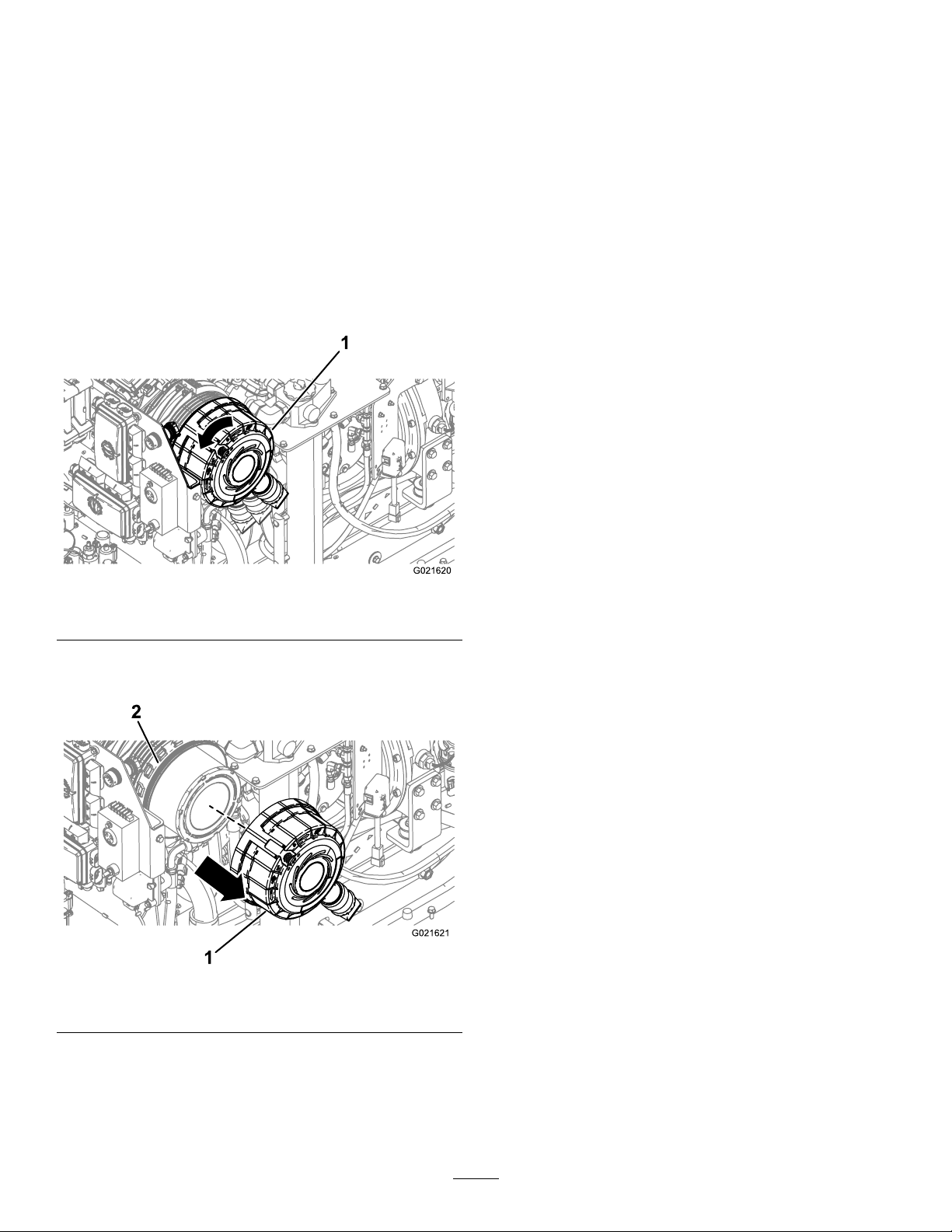
3.Cleantheoutsideoftheair-cleanercanisterwitha
clean,dampcloth.
4.Checktheair-cleanercanisterfordamagewhichcould
causeanairleak.Replaceadamagedaircleanerbody .
Important:Servicetheair-cleanerlteronlywhen
“CheckAirFilter”isdisplayedonthescreen.
Changingtheairlterbeforeitisnecessaryonly
increasesthechanceofdirtenteringtheengine
whenthelterisremoved.
5.Pullthelatchfortheair-cleanercoveroutward(Figure
114).
6.Rotatetheltercovercounterclockwisesothatthe
dustcapisatthe4o’clockposition(Figure115).
InstallingtheAir-cleanerCover
1.Parkthemachineonalevelsurface,stoptheengine,
andremovetheignitionkey.
2.Alignthedustcapontheaircleanerltercovertothe
5o’clockposition.
3.Aligntheaircleanerltercoverwiththelterhousing
(Figure116).
4.Rotatetheaircleanerltercoverclockwise,sothatthe
dustcapisatthe4o’clockposition(Figure115).
5.Pushthelatchontheaircleanerltercoverinward
untilitisfullyseated(Figure115).
Figure115
1.Air-cleanercover
7.Pulltheair-cleanercoverawayfromthelterhousing
andremovethecover(Figure116).
Figure116
1.Air-cleanercover2.Filterhousing
8.Cleananydebrisfrominsidethecover.
Important:If“CheckAirFilter”isnotdisplayed
onthescreen,donotremovetheairlters.
79
Page 80
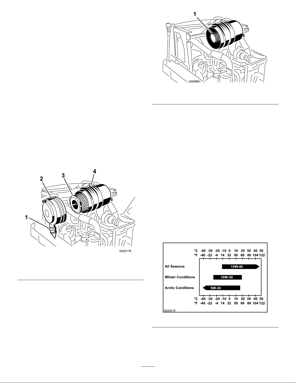
ServicingtheAir-cleanerFilter
2
3
4
G022176
°C°F-40
-30 -20 -10 0 10 20 30 40 50
-40 -22 -4 14 32 50 68 86 104 122
All Seasons
Winter Conditions
Arctic Conditions
°C°F-40
-30 -20 -10 0 10 20 30 40 50
-40 -22 -4 14 32 50 68 86 104 122
15W -40
10W -30
5W-30
G022415
ServiceInterval:Every250hours
Replacetheltersonlywhenthe“CheckAirFilter”
indicatorappearsonthedisplayscreen;referto
CheckingtheAir-cleanerIndicator(page78).
Note:ContactyourAuthorizedT oroDealertoorder
replacementlters.
1.Parkthemachineonalevelsurface,stoptheengine,
andremovetheignitionkey.
2.Openthefronthood;refertoOpeningtheFront
Hood(page72).
3.Beforeremovingthelter,cleanoutalldebrisfrom
theinsideofthelterbodyusinglow-pressureair(40
psi,cleananddry).
Important:Avoidusinghighpressureairwhich
couldforcedirtthroughthelterintotheintake
tract.Thiscleaningprocesspreventsdebrisfrom
migratingintotheintakewhentheprimarylter
isremoved.
4.Removetheprimarylter(Figure117).
Important:Donotcleantheusedlter.
Figure118
1.Safetylter
6.Insertthenewprimarylterbyapplyingpressureto
theouterrimoftheltertoseatitinthecanister.Do
notapplypressuretotheexiblecenterofthelter.
7.Removetherubberoutletvalvefromthecover,clean
thecavity,andreplacetheoutletvalve.
8.Installthecover;refertoInstallingtheAir-cleaner
Cover(page79).
ServicingtheEngineOiland
Filter
Theengineisshippedwithoilinthecrankcase;however,
checktheoillevelbeforeandafteryourststarttheengine.
Crankcasecapacity:7.5L(8USqt)withthelter.
Useonlyhigh-qualitySAE15W -40heavy-dutyengineoilwith
anAPIclassicationofCH-4orhigher.
WhileSAE15W-40oilwithanAPIclassicationofCH-4or
higherisrecommendedformostclimates,refertoFigure119
foroilviscosityrecommendationsforextremeclimates.
1.Rubber-outletvalve
2.Air-cleanerlatch4.Air-cleanerbody
Figure117
3.Air-cleaner,primarylter
5.Inspectthenewlterforshippingdamage,checking
thesealingendofthelterandthebody.Donotuse
adamagedelement.
Important:Donotcleantheusedsafetylter
(Figure118).Replacethesafetylterwithanew
oneafterevery3primarylterservices,orwhen
indicatedbythe“CheckAirFilter”onthedisplay
screen.Ifyouarenotreplacingit,donotremove
thesafetylter.
Figure119
Note:Limiteduseoflow-viscosityoilssuchasSAE10W-30
withanAPIclassicationofCH-4orhighercanbeusedfor
easierstartingandprovidingsufcientoilowatambient
temperaturesbelow-5°C(23°F).However,continuoususe
80
Page 81
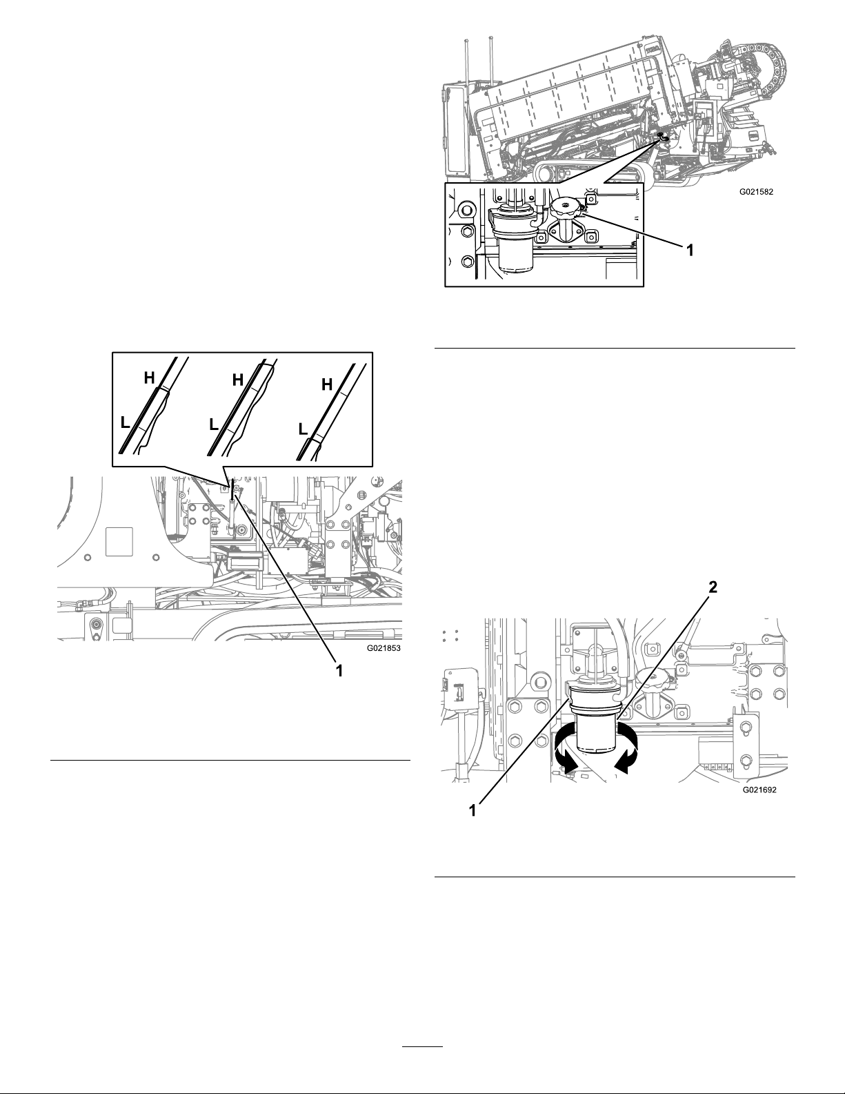
oflowviscosityoilcandecreaseenginelifebecauseofwear
G021582
1
(Figure119).
ToroPremiumEngineOilisavailablefromanAuthorized
ToroServiceDealerineither15W -40or10W-30viscosity
withAPIclassicationCH-4orhigher.Seethepartscatalog
forpartnumbers.
CheckingtheEngine-oilLevel
ServiceInterval:Beforeeachuseordaily—Checkthe
engine-oillevel.
1.Parkthemachineonalevelsurface,stoptheengine,
andremovetheignitionkey.
2.Openthefronthood;refertoOpeningtheFront
Hood(page72).
3.Removethedipstick(Figure120),andwipeitclean.
Figure120
Operator’sside
Figure121
1.Oil-llcap
B.Installtheoilllcapandthedipstick.
ChangingtheEngine-oilFilter
ServiceInterval:Every250hours
1.Parkthemachineonalevelsurface,stoptheengine,
andremovetheignitionkey.
2.Openthefronthood;refertoOpeningtheFront
Hood(page72).
3.Alignadrainpanorseveralragsundertheoillterand
theoil-lteradapter(Figure122).
1.Dipstick
4.Insertthedipstickintotheoillltube,pullthedipstick
outagain,andreadtheoillevelonthedipstick.
Note:Theoillevelonthedipstickshouldbeatthe
HighmarkorbetweentheLowandHighmarks.If
theoilisbelowtheLowmark,completethefollowing
procedure:
A.Removethellcap(Figure121)andaddoiluntil
thelevelreachestheHighmark.Donotoverll.
Important:Useanoilcanisterwitha
bendablehoseorafunneltollthemachine
withoil.
Figure122
1.Oil-lteradapter2.Oillter
4.Rotatetheoilltercounterclockwiseandremovethe
oillter(Figure122).
Note:Discardtheoillter.
5.Usingacleanrag,wipecleanthesurfaceoftheoil-lter
adapterwheretheoillterseatswithacleanrag.
6.Fillthenewoillterwiththespecied-engineoil.
81
Page 82
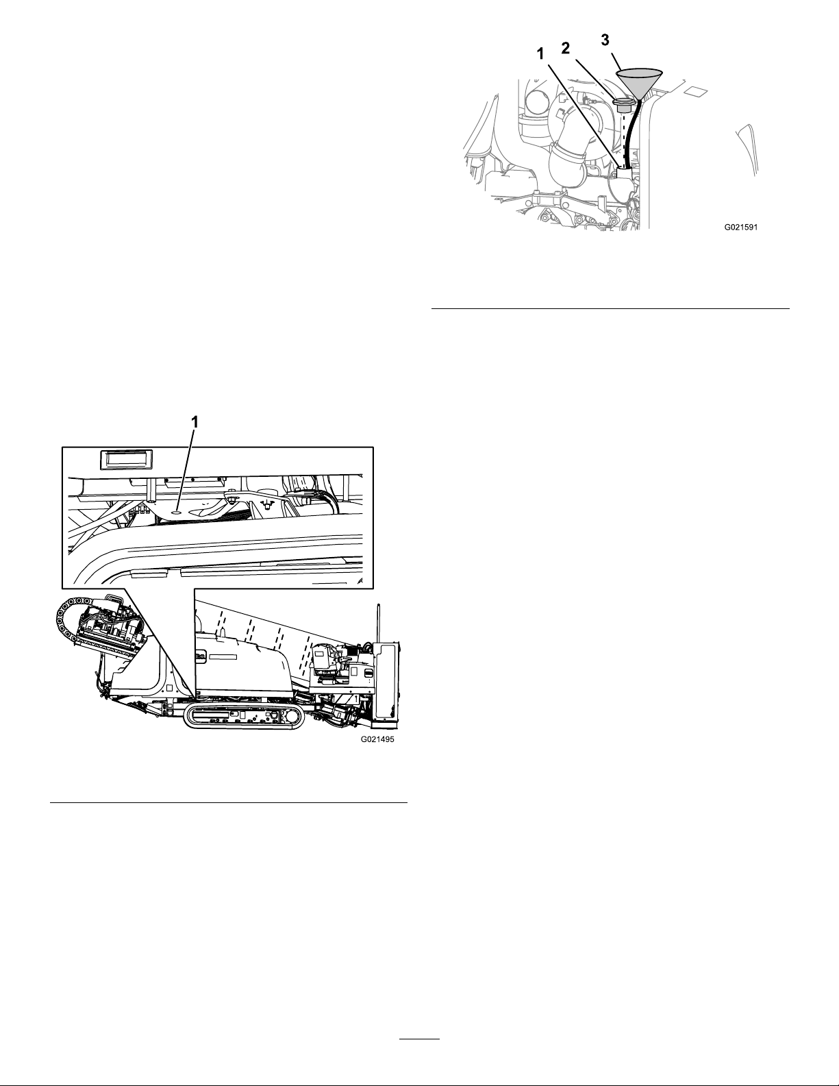
7.Applyathinlayerofthespecied-engineoiltotheseal
oftheoillter.
8.Aligntheoilltertotheoil-lteradapterandrotate
itclockwiseuntilthesealoftheoilltercontactsthe
oil-lteradapter(Figure122).
Note:Donotuseanoillterstrapwrenchtoinstall
thenewoillter.Thewrenchcandentanoillterand
thereforecausealeak.
9.Handtightentheoillteranadditional1/2turn
(Figure122).
10.Removetheoilpanorragsyouplacedinstep3and
disposeoftheusedoilaccordingtolocalcodes.
ChangingtheEngineOil
ServiceInterval:Every250hours
1.Parkthemachineonalevelsurface,stoptheengine,
andremovetheignitionkey.
2.Removethedrainplug(Figure123).
Figure124
1.Fillerneck3.Funnel
2.Oil-llcap
Note:Useafunnelwithaexible,attachedhoseto
directtheengineoilintotheengine.
9.Fillthecrankcasewithapproximately7.5L(8USqt)of
thespeciedengineoil;refertoServicingtheEngine
OilandFilter(page80).
10.Installtheoil-llcap.
11.Starttheengine,runitatidleforabout2minutes,and
checkforoilleaks.
12.Stoptheengineandremovethekey.
13.Waitfor2or3minutesandchecktheoillevel;referto
CheckingtheEngine-oilLevel(page81).
AdjustingtheValveClearance
ServiceInterval:Aftertherst250hours
Every2,000hours
Figure123
1.Engine-oildrainplug
3.Cleanthethreadsonthedrainplugandapply3layers
ofPTFEsealingtape.
4.Draintheoilintoadrainpan.
5.Whentheoilstops,installthedrainplug.
6.Changetheengine-oillter;refertoChangingthe
Engine-oilFilter(page81).
7.Installthedrainplugontothedraintting(Figure123).
8.Removetheoil-llcapfromthellerneckbypulling
thecapupward.
Refertotheengineowner’smanual,includedwiththe
machine,fortheadjustmentprocedure.
Ifyoucannotadjustthevalveclearance,contactyour
AuthorizedToroServiceDealerforvalveadjustment.
82
Page 83
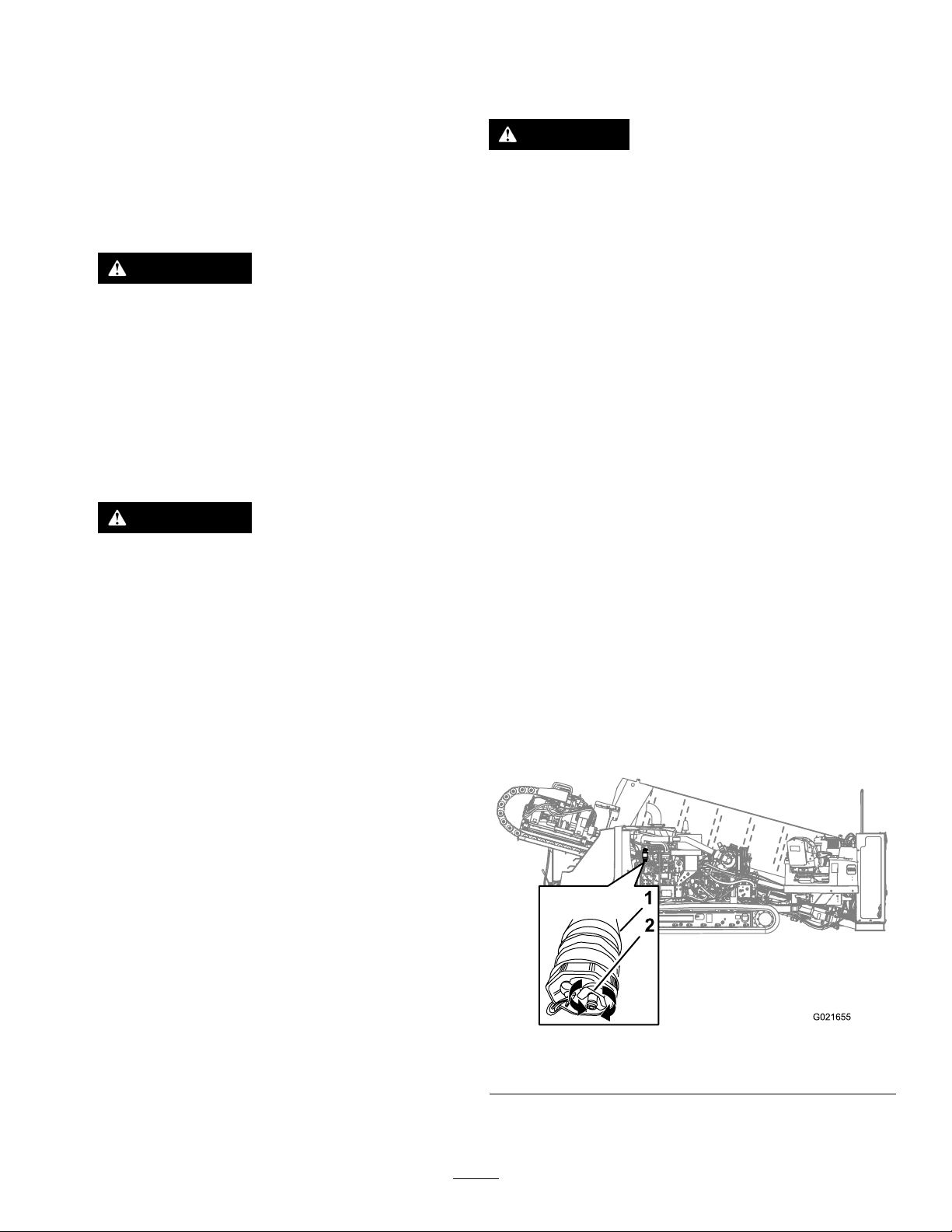
ServicingtheSparkArrestor
(IfEquipped)
ServiceInterval:Every250hours—Clearthesparkarrestor
inthemuferofcarbonbuildup.
1.Parkthemachineonalevelsurface,stoptheengine,
andremovetheignitionkey.
2.Removethepipeplugfromtheclean-outportatthe
lowersideofthemufer.
WARNING
Themufermaybehotandcouldcause
injury.
Becarefulnottotouchthehotmufer.
3.Starttheengine.
4.Plugthenormalmuferexitwithablockofwoodor
metalplatesothattheexhaustowwillbeforcedout
oftheclean-outport.Continuetoblocktheexituntil
carbondepositsceasecomingoutoftheport.
WARNING
Donotstandinlinewiththeclean-outport;
hotelementscouldcauseseriousinjury.
Wearsafetyglasses.
5.Stoptheengineandreplacethepipeplug.
FuelSystem
Maintenance
DANGER
Undercertainconditions,dieselfuelandfuel
vaporsarehighlyammableandexplosive.Are
orexplosionfromfuelcanburnyouandothersand
cancausepropertydamage.
•Useafunnelandllthefueltankoutdoors,in
anopenarea,whentheengineisoffandiscold.
Wipeupanyfuelthatspills.
•Donotllthefueltankcompletelyfull.Addfuel
tothefueltankuntilthelevelis25mm(1inch)
belowthebottomofthellerneck.Thisempty
spaceinthetankallowsthefueltoexpand.
•Neversmokewhenhandlingfuel,andstayaway
fromanopenameorwherefuelfumesmaybe
ignitedbyaspark.
•Storefuelinaclean,safety-approvedcontainer
andkeepthecapinplace.
DrainingWaterfromtheFuel
Filter
ServiceInterval:Every50hours—Checkthefuel-water
separatorforwaterandsediment.
1.Parkthemachineonalevelsurface,stoptheengine,
andremovetheignitionkey.
2.Openthefronthood;refertoOpeningtheFront
Hood(page72).
3.Alignadrainpanunderthesecondary-fuellter
(Figure125).
Figure125
1.Secondary-fuellter
4.Rotatethedrainvalveatthebottomofthe
secondary-fuellter2or3turnscounterclockwise,
83
2.Drainvalve
Page 84
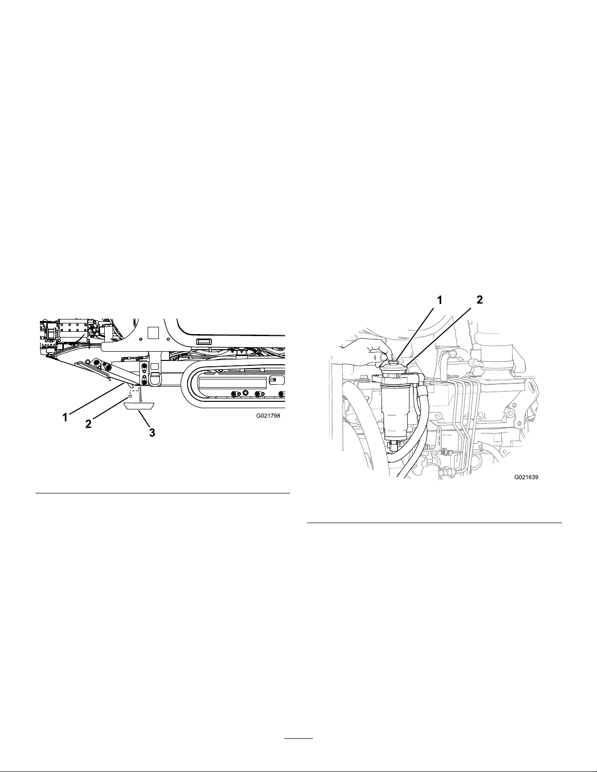
anddrainanywaterandsedimentfromthefuellter
1
2
3
G021798
(Figure125).
Note:Ifthefuel-waterseparatorhasanywateror
sediment,alsodrainthewaterandsedimentfrom
thefueltank;refertoDrainingWaterfromtheFuel
Tank(page84).
5.Whencleanfuelappears,rotatethedrainvalve
clockwiseuntilitisclosed.
Note:Donotovertightenthedrainvalve.
6.Primethefuelsystem;refertoPrimingtheFuel
System(page84).
PrimingtheFuelSystem
Note:Primethefuelsystemwheneveranyofthefollowing
occur:
•Youdrainedwaterfromthefuellter.
•Youreplacedthefuellter.
•Yourantheengineuntilthefueltankisemptyordrained
thefueltank.
1.Parkthemachineonalevelsurface,stoptheengine,
andremovetheignitionkey.
2.Openthefronthood;refertoOpeningtheFront
Hood(page72).
DrainingWaterfromtheFuel
Tank
1.Parkthemachineonalevelsurface,stoptheengine,
andremovetheignitionkey.
2.Placeadrainpanunderthedrainpluginthefueltank.
3.Loosenthedrainpluguntilthewaterandsediment
drainout(Figure126).
Figure126
1.Fueltank3.Drainpan
2.Drainplug
3.Ensurethattheengineandtheexhaustsystemarecool.
4.Ensurethatthefueltankisatleast1/4full.
5.Rotatethebattery-disconnectswitchclockwisetothe
Onposition.
6.Locatetheprimingbuttononthetopofthelter
adapterforthesecondary-fuellter(Figure127).
Figure127
4.Cleanthethreadsonthedrainplugandapply3layers
ofPTFEsealingtape.
5.Whencleanfuelappears,installthedrainplugand
tightenitsecurely.
6.Checkthefueltankdrainplugforleaks.
1.Primingbutton2.Filteradapter
7.Pressdownandreleasetheprimingbuttonrepeatedly
untilyoufeelresistancewhenpressingthepriming
button(Figure127).
8.Iftheenginedoesnotstartafterprimingthefuel
systemandmakingseveralattemptstostarttheengine,
bleedthehigh-pressurefuellines;refertoyourengine
owner’smanualorcontactyourAuthorizedToro
ServiceDealerforassistance.
84
Page 85
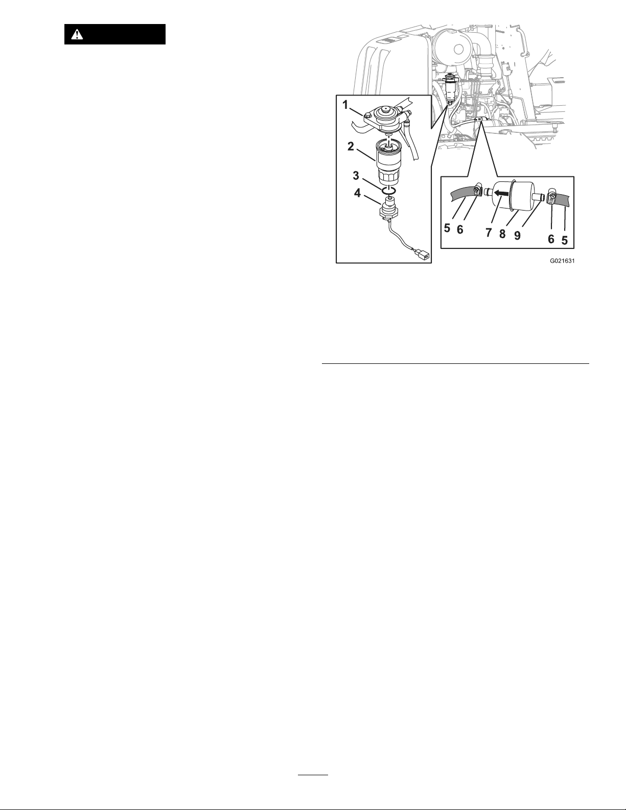
WARNING
Thefuelsystemisunderhighpressure.
Bleedingthesystemwithoutproper
precautionsandtrainingcouldresultininjury
toyoufrominjecteduidorreorexplosion.
Readtheengineowner’smanualforthe
properbleedingprocedureorcontactyour
AuthorizedT oroDealer.
ReplacingtheFuelFilters
ServiceInterval:Every250hours—Replacetheprimary
andsecondary,fuellters.
ReplacingthePrimary,FuelFilter
1.Parkthemachineonalevelsurface,stoptheengine,
andremovetheignitionkey.
2.Openthefronthood;refertoOpeningtheFront
Hood(page72).
3.Placecleanragsundertheprimary,fuellter.
4.Loosenthehoseclampsandseparatetheprimary,fuel
lterfromthefuelhoses(Figure128).
Figure128
1.Filteradapter6.Hoseclamp
2.Secondary-lterelement
3.O-ring8.Primaryfuellter
4.Watersensor9.Fitting
5.Fuelsensor
7.Arrow
Note:Donotremovethehoseclampsfromthehoses.
Note:Discardthefuellter.
5.Alignthenew,primary,fuelltertothehoseswiththe
arrowprintedonthelterpointingforward(Figure
128).
6.Slipthehosesoverthehosettingoftheprimary,fuel
lter,andtightenthehoseclamps(Figure128).
7.Replacethesecondary,fuellter;refertoReplacingthe
Secondary,FuelFilter(page85).
ReplacingtheSecondary,FuelFilter
1.Removethesecondary,fuellterasfollows:
A.Cleanthesecondary,fuel-lterassemblyandthe
surroundingarea.
B.Completelydrainwaterfromthelter;referto
DrainingWaterfromtheFuelFilter(page83).
C.Firmlygraspthesecondary-fuel-lterelement,
androtatethewatersensorcounterclockwise,and
removethewatersensor(Figure128).
Note:Retainthewatersensoranddiscardthe
O-ring.
D.Firmlygraspthesecondary-fuel-lterelement,
androtateitcounterclockwise,andremovethe
lterfromthelteradapter(Figure128).
Note:Discardthelterelement.
E.Cleanthelteradapterwithacleanrag.
2.Installthesecondary,fuellterasfollows:
A.Applyathinlmofcleanfueltothesealonthe
fuel-lterelement.
B.Alignthenewsecondary-lterelementtothe
lteradapter(Figure128).
C.Rotatethesecondary-lterelementuntiltheseal
contactsthelteradapter,thenrotatethelter
elementanadditional3/4turn.
Important:Donotusealterwrenchto
tightenthelter.Youcoulddamagethelter
andcausealeak.
D.AlignthenewO-ringoverthewatersensor
(Figure128).
E.Alignthewatersensortothebottomofthe
secondary,fuellter(Figure128).
F.Firmlygraspthesecondary-lterelementand
rotatethewatersensorclockwiseuntilhand-tight
(Figure128).
3.Primethefuelsystem;refertoPrimingtheFuel
System(page84).
4.Starttheengineandcheckforleaksatthefuellters.
85
Page 86

CheckingFuelLinesand
Connections
ServiceInterval:Every500hours/Yearly(whichever
comesrst)—Inspectthefuellinesand
connections.
ElectricalSystem
Maintenance
ServicingtheBattery
Inspectthefuellinesandconnectionsfordeterioration,
damage,orlooseconnections.
DrainingandCleaningtheFuel
Tank
ServiceInterval:Every1,000hours/Yearly(whichever
comesrst)—Drainandcleanthefuel
tank.
Drainandcleanthetankifthefuelsystembecomes
contaminatedorifthemachinewillbestoredforanextended
periodoftime.Usecleanfueltoushoutthetank.Referto
DrainingW aterfromtheFuelTank(page84)fordraining
instructions.
Note:Performthisprocedurewhenthefuellevelislow ,to
avoidtheneedtodrainlargevolumesoffuel.
ServiceInterval:Every50hours—Checkthebattery
condition
WARNING
CALIFORNIA
Proposition65Warning
Batteryposts,terminals,andrelated
accessoriescontainleadandleadcompounds,
chemicalsknowntotheStateofCalifornia
tocausecancerandreproductiveharm.
Washhandsafterhandling.
Important:Beforeweldingonthemachine,disconnect
thenegativecablefromthebatterytopreventdamageto
theelectricalsystem.Also,disconnecttheengineand
machinecontrollersbeforeweldingonthemachine.
Note:Checkthebatteryconditionweeklyorafterevery
50hoursofoperation.Keeptheterminalsandtheentire
batterycasecleanbecauseadirtybatterywilldischargeslowly.
Tocleanthebattery,washtheentirecasewithasolution
ofbakingsodaandwater.Rinsewithclearwater.Coat
thebatterypostsandcableconnectorswithGrafo112X
(skin-over)grease(ToroPartNo.505-47)orpetroleumjelly
topreventcorrosion.
WARNING
Exposuretobatteryacidorabatteryexplosioncan
causeseriouspersonalinjury.
Beforeyouserviceabattery,wearfaceprotection,
protectivegloves,andprotectiveclothing.
86
Page 87
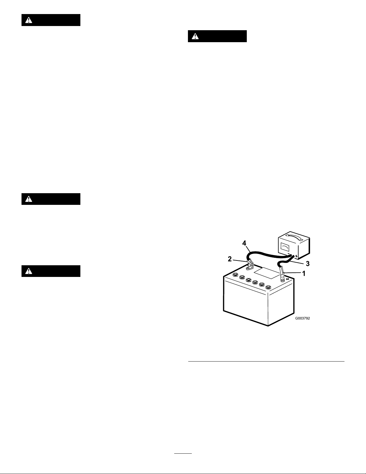
WARNING
1
2
3
4
G003792
ChargingtheBattery
Abatterycontainssulfuricacid,whichcancause
seriousburns;andtheycanproduceexplosive
gases.
•Avoidcontactwithskin,eyes,orclothing;ush
affectedareaswithwater.
•Iftakeninternally,drinklargequantitiesofwater
ormilk.
Do not
inducevomiting.Seekmedical
attentionimmediately.
•Keepsparks,ames,andlitcigarettesandcigars
awayfromthebattery.
•Ventilatethebatterywhenyouarechargingitor
usingitinanenclosedarea.
•Weareyeprotectionwhenworkingneara
battery.
•Washyourhandsafterhandlingabattery.
•Keepthebatteryoutofthereachofchildren.
WARNING
Ifyoutrytochargeorjumpstartafrozenbattery,it
couldbeexplosive,causingpersonalinjurytoyou
orothersinthearea.
WARNING
Chargingthebatteryproducesgassesthatcan
explode.
Donotsmokenearthebatteryandkeepsparksand
amesawayfrombattery.
Important:Keepthebatteryfullycharged.Thisis
especiallyimportanttopreventbatterydamagewhen
thetemperatureisbelow32°F(0°C).
1.Parkthemachineonalevelsurface,stoptheengine,
andremovetheignitionkey.
2.Openthefronthood;refertoOpeningtheFront
Hood(page72).
3.Cleantheexteriorofthebatterycaseandthebattery
posts.
Note:Connecttheleadsofthebatterychargerto
batterypostsbeforeconnectingthechargertothe
electricalsource.
4.Lookatthebatteryandidentifythepositiveand
negativebatteryposts.
5.Connectthepositiveleadofthebatterychargertothe
positivebatterypost(Figure129).
Topreventthebatteryelectrolytefromfreezing,
keepthebatteryfullycharged.
WARNING
•Sparksoraamecancausehydrogengasina
batterytoexplode.
•Whenyoudisconnectthebatterycables,
disconnectthenegative(-)cablerst.
•Whenyouconnectthebatterycables,connect
thenegative(-)cablelast.
•Donotshort-circuitthebatterypostswitha
metalobject.
•Donotweld,grind,orsmokenearabattery.
Note:Theelectricalsysteminthismachineis12volts.
Figure129
1.Positivebatterypost
2.Negativebatterypost
6.Connectthenegativeleadofthebatterychargertothe
negativebatterypost(Figure129).
7.Connectthebatterychargertotheelectricalsource.
Important:Donotoverchargethebattery.
Note:Chargethebatteryashowninbatterycharging
table.
3.Red(+)chargerlead
4.Black(-)chargerlead
87
Page 88
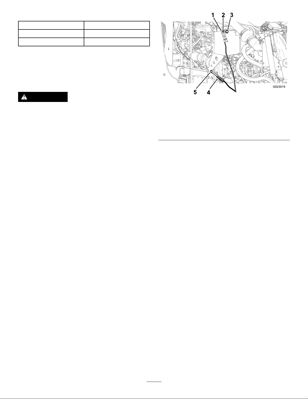
Battery-chargerTable
ChargersettingChargingtime
4to6amperes30minutes
25to30amperes10to15minutes
8.Whenthebatteryisfullycharged,unplugthecharger
fromtheelectricalsource,thendisconnectthecharger
leadsfromthebatteryposts(Figure129).
Jump-startingtheMachine
WARNING
Jump-startingthebatterycanproducegassesthat
canexplode.
Donotsmokenearthebatteryandkeepsparksand
amesawayfrombattery.
Note:Thisprocedurerequires2peopletoperform.Ensure
thatthepersonmakingtheconnectionswearstheproperface
protection,protectivegloves,andclothing.
1.Parkthemachineonalevelsurface,stoptheengine,
andremovetheignitionkey.
2.Openthefronthood;refertoOpeningtheFront
Hood(page72).
3.EnsurethatallcontrolsareintheNeutralposition.
4.Sitintheoperatorseatandhavetheotherpersonmake
theconnections.
Note:Ensurethatthejumperbatteryisa12-volt
battery.
Important:Ifyouareusinganothermachine
forpower,ensurethatthe2machinesarenot
touchingeachother.
5.Preparetostarttheengine;refertoStarting/Stopping
theEngine(page57).
Figure130
1.Jumper-cableclamp
(positive)
2.Jumppost5.Jumper-cableclamp
3.Cover
4.Groundpoint(unpainted
bolt)
(negative)
7.Connectthepositive(+)jumpercabletothejumppost
(Figure130).
8.Connectthenegative(-)jumpercabletoaground
point,suchasanunpaintedboltorchassismember
(Figure130).
9.Starttheengine;refertoStarting/Stoppingthe
Engine(page57).
Important:Iftheenginestartsandthenstops,
do not
motorstopsturning.
operatethestartermotoruntilthestarter
Do not
operatethestarter
motorformorethan30secondsatonetime.Wait
30secondsbeforeoperatingthestartermotorto
coolthemotorandtobuildupthechargeinthe
battery.
10.Whentheenginestarts,havetheotherperson
disconnectthenegative(-)jumpercablefromthe
frameandthendisconnectthepositive(+)jumper
cable(Figure130).
6.Removethecoverfromthejumppost(Figure130).
88
Page 89
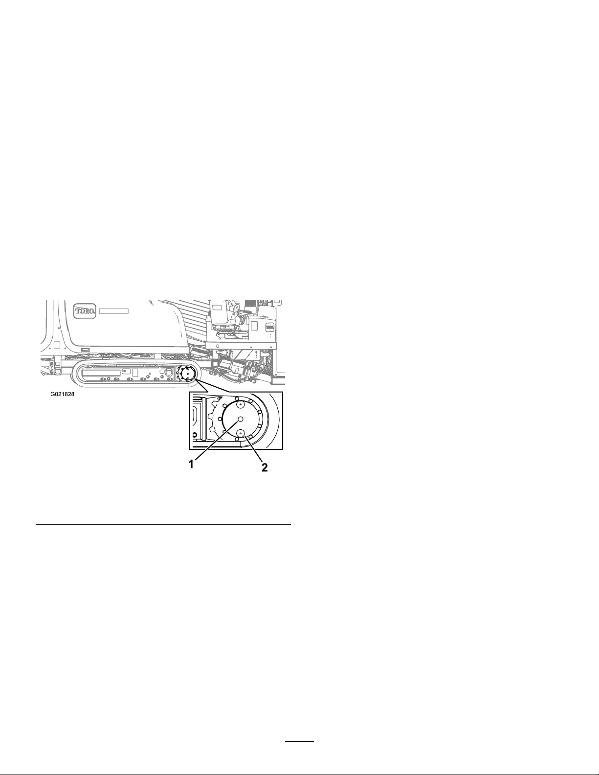
DriveSystem
Maintenance
CheckingtheOilLevelforthe
PlanetaryDrive
ChangingtheOilforthe
PlanetaryDrive
ServiceInterval:Aftertherst250hours—Changethe
planetaryoil.
Every800hours—Changetheplanetaryoil(oryearly,
whichevercomesrst).
ServiceInterval:Every50hours—Checktheplanetary-drive
oillevel(Also,checkifexternalleakage
isobserved).
Oilspecication:SAE85W -140APIclassicationlevelGL4
Planetarydriveoilcapacity:approximately1.4L(1.5USqt)
ToroPremiumGearOilisavailablefromanAuthorizedToro
ServiceDealer.Seethepartscatalogforpartnumbers.
1.Parkthemachineonalevelsurface,stoptheengine,
andremovetheignitionkey.
2.Cleantheareaaroundtheoil-levelplugwithacleaning
solvent(Figure131).
Note:Changetheoilwhenitiswarm,ifpossible.
1.Parkthemachineonalevelsurface.
2.Cleantheareaaroundtheoil-levelplug(Figure131).
3.Rotatetheplanetarydriveuntiltheoil-drainplugis
directlybelowtheoil-levelplug(Figure131).
4.stoptheengineandremovetheignitionkey.
5.Placeadrainpanundertheoil-drainplug.
6.Removetheoil-levelplugandtheoil-drainplug.
7.Installtheoil-drainplug.
8.Fillthechaindriveplanetarywithoiluntiltheoileven
withthebottomoftheoil-levelplughole.
9.Installtheoil-levelplug.
10.Repeatsteps1through9tochangetheplanetary-drive
oilontheothersideofthemachine.
CheckingtheOilforthe
GearboxDrive
Figure131
1.Oil-levelplug2.Oil-drainplug(6o’clock
position)
3.Rotatetheplanetarydriveuntiltheoillevelandthe
oil-drainplugsareverticaltotheground(atthe6
o’clockposition)asshowninFigure131.
4.Removetheoil-levelplug(Figure131).
Note:Theoilleveliscorrectwhenitisuptothe
bottomoftheoil-levelplughole.
5.Iftheoilisbelowthebottomofthehole,addthe
speciedoiluntiltheoilislevelwiththebottomof
thehole.
6.Installandtightentheoil-levelplug.
7.Repeatsteps1through6tochecktheplanetary-drive
oillevelontheothersideofthemachine.
ServiceInterval:Aftertherst100hours—Checkthe
gearboxdriveoil.
Every500hours—Checkthegearboxdriveoil(or
yearly,whichevercomesrst).
Oilspecication:SAE85W -140APIclassicationlevelGL4
Planetary-driveoilcapacity:approximately2.7L(5.75US
pt)
1.Parkthemachineonalevelsurface,stoptheengine,
andremovetheignitionkey.
2.Checktheoillevelonthesight-glassonthegearbox
drive(Figure132).
Note:Theoillevelshouldcoverhalfofthesight-glass.
89
Page 90
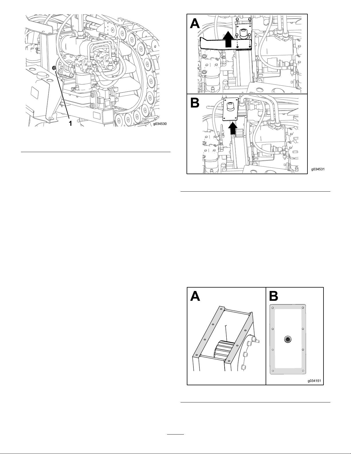
Figure132
1.Sight-glass
3.Removethebreathercapandaddtheoilintothe
gearboxdriveuntiltheoillevelonthesight-glassisat
leasthalffull(Figure132).
Figure133
ChangingtheOilforthe
GearboxDrive
ServiceInterval:Aftertherst100hours—Changethe
gearbox-driveoil.
Every500hours—Changethegearbox-driveoil(or
yearly,whichevercomesrst).
Note:Changetheoilwhenitiswarm,ifpossible.
1.Parkthemachineonalevelsurfaceandmovethe
carriageallthewaytotherearstop.
2.Stoptheengineandremovetheignitionkey.
3.Removethe4boltsontheguardplateandgearbox
(BoxAofFigure133).
4.Removetheguardplate(BoxAofFigure133).
5.Removethecoveronthegearboxandsyphontheoil
out(BoxBofFigure133).
6.Fillthegearboxwithoiluntiltheoillevelinthesight
glassismorethanhalffull(Figure132).
7.Cleanthesealantoffofthegearboxboxandcover
(Figure134).
Figure134
8.Putnewautomotive-gradeRTVsealantaroundthe
edgeofthecover(BoxBofFigure134).
90
Page 91

9.Placetheguardbackintoplaceandinstallthe2bolts
(BoxAofFigure133).
10.Installthe2otherboltssecuringthelidontothe
gearbox(BoxAofFigure133).
11.Torquetheboltsto23to29N∙m(17to21ft-lb).
ServicingtheTracks
ServiceInterval:Beforeeachuseordaily—Checkthetrack
tension.
5.Removeexcessgreasefromaroundthevalve.
6.Installthecoverandretainingbolts.
7.Repeatsteps2through6totightenthetracktension
ontheotherside.
LooseningtheTrackTension
Ifthetrackseemstight,loosenthetracktensionasfollows:
1.Parkthemachineonalevelsurface,stoptheengine,
andremovetheignitionkey.
WARNING
Greaseinthehydraulictrackishighlypressurized;
ensurethatthetrack-tensiongreasevalveisnot
loosenedmorethanonerevolutionatatime.
Ifyouremovethetrack-tensiongreasevalvefound
inthehydraulic-tracktensionerorloosenittoo
much,greasecanbereleasedandmaycause
seriousinjuryordeath.
TighteningtheTrackTension
Ifthetrackseemsloose,tightenthetracktensionasfollows:
1.Parkthemachineonalevelsurface,stoptheengine,
andremovetheignitionkey.
2.Removedirtanddebrisfoundaroundthetrack-tension
greasevalve(Figure135).
Important:Ensurethattheareasurrounding
thetrack-tensiongreasevalveiscleanbefore
beginningtoadjustthetracktension.
3.Removetheretainingboltsandcoverthathousethe
track-tensiongreasevalve.
2.Removedirtanddebrisfoundaroundthetrack-tension
greasevalve(Figure135).
Important:Ensurethattheentirearea
surroundingthetrack-tensiongreasevalveisclean
beforebeginningtoadjustthetracktension.
3.Removetheretainingboltsandcoverthathousethe
track-tensiongreasevalve.
4.Turnthetrack-tensiongreasevalvecounterclockwise
nomorethan1revolution(Figure135).
Note:Aone-revolutionturnwillreleasegreaseand
loosenthetrack.
5.Whenthetensionreaches3,200psi,turnthe
track-tensiongreasevalveclockwisetotightenit.
6.Removeexcessgreasefromaroundthevalve.
7.Installthecoverandretainingbolts.
8.Repeatsteps2through7toloosenthetracktensionon
theotherside.
4.Applygreasetothettinguntilthetensionreaches
22,063kPa(3,200psi)asshowninFigure135.
Figure135
Track-tensiongreasevalveshown
91
Page 92
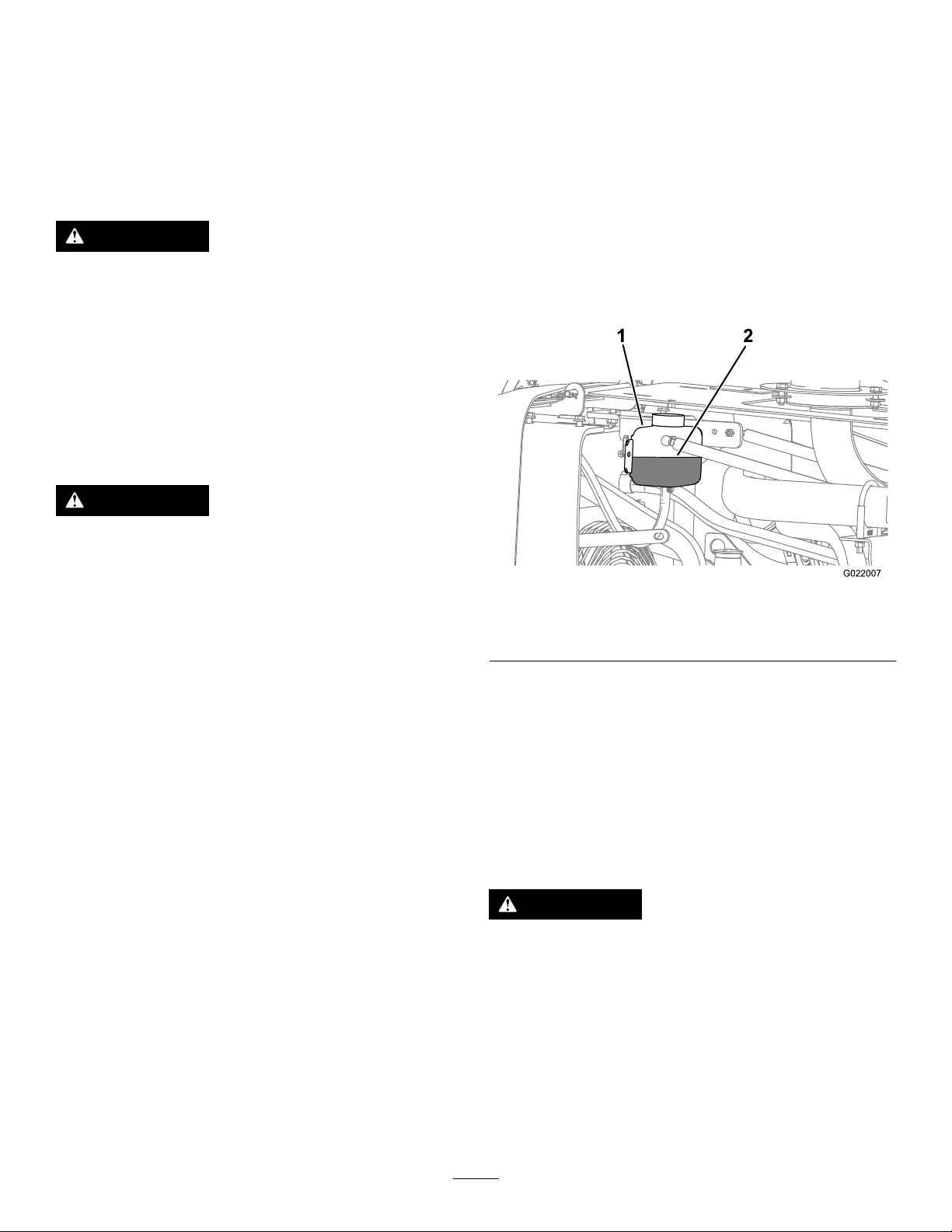
CoolingSystem
1
2
G022007
Maintenance
Coolantspecication:50/50solutionofethylene-glycol
antifreezeandwaterorequivalent
EngineandRadiatorcoolantcapacity:16.77L(17.7US
qt)
CheckingtheCoolantLevelin
theReservoir
ServiceInterval:Beforeeachuseordaily
Important:Donotremovetheradiatorllercapduring
thisprocedure.
1.Parkthemachineonalevelsurface,stoptheengine,
andremovetheignitionkey.
WARNING
Ifyouremovetheradiatorcapfromahotengine,
hotcoolantcouldspray,causingscalding.
•Wearfaceprotectionwhenopeningtheradiator
cap.
•Allowthecoolingsystemtocooldowntobelow
50°C(120°F)beforeremovingtheradiatorcap.
•Followtheinstructionsforcheckingthe
maintainingtheenginecoolingsystem.
WARNING
Coolantistoxic.
•Keepcoolantawayfromchildrenandpets.
•Ifyouarenotusingthesamecoolantagain,
disposeofitaccordingtolocalenvironmental
regulations.
2.Allowtheenginetocool.
3.Openthefronthood;refertoOpeningtheFront
Hood(page72).
4.Checkthecoolantlevelinthereservoir(Figure136).
Figure136
1.Reservoir
5.Addthespeciedcoolantuntilthecoolantlevelis1/2
thereservoircapacity .
2.Coolantlevel(1/2reservoir
height)
Note:Ensurethatthecoolantsolutionisthoroughly
mixedbeforellingthereservoir.
CheckingtheCoolantLevelin
theRadiator
ServiceInterval:Every50hours
WARNING
Iftheenginehasbeenrunning,theradiatorwillbe
pressurizedandthecoolantinsidewillbehot.If
youremovethecap,coolantmaysprayout,causing
severeburns.
•Donotremovetheradiatorcaptocheckcoolant
levels.
•Donotremovetheradiatorcapwhentheengine
ishot.Allowtheenginetocoolforatleast15
minutesoruntiltheradiatorcapiscoolenough
totouchwithoutburningyourhand.
92
Page 93
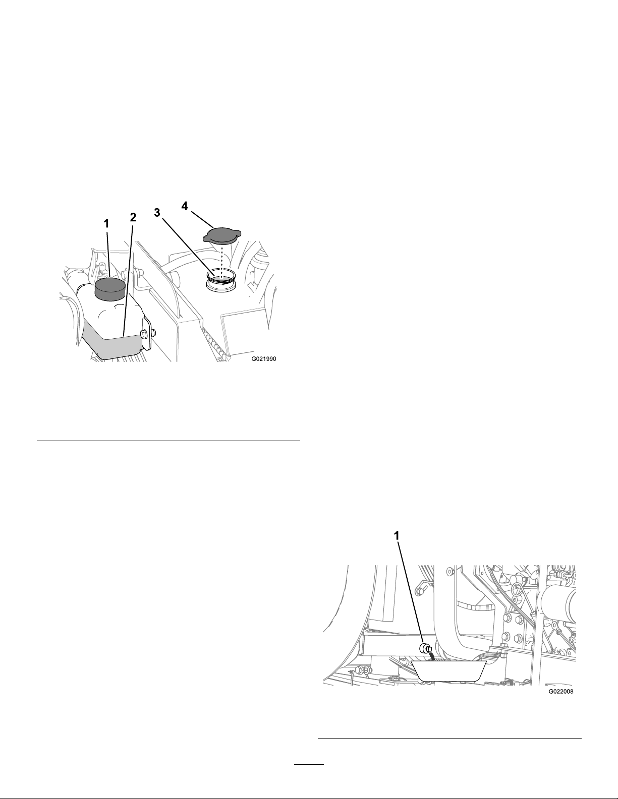
Note:Thecoolingsystemislledwitha50/50solutionof
waterandethylene-glycolantifreeze.
1.Parkthemachineonalevelsurface,stoptheengine,
andremovetheignitionkey.
2.Allowtheenginetocool.
3.Openthefronthoodandrearhood;refertoOpening
theFrontHood(page72)andOpeningtheRear
Hood(page73).
4.Removetheradiatorcapfromthellerneckofthe
radiatorandcheckthecoolantlevel(Figure136and
Figure137),
Note:Thecoolantshouldbeuptothellerneck.
CheckingtheConcentrationof
theCoolant
ServiceInterval:Every1,000hours/Yearly(whichever
comesrst)—Checktheconcentration
ofthecoolantbeforethewinterseason.
Testtheconcentrationofethyleneglycol-basedantifreeze
inthecoolant.Ensurethatthecoolanthasa50%ethylene
glycoland50%watermixtureorequivalent.
Note:A50%ethyleneglycoland50%watermixturewill
protecttheengineto-37°C(-34°F)throughouttheyear.
Usingaconcentrationtester,checktheconcentrationof
thecoolantmixturetoensurethatitis50%ethyleneglycol
and50%waterorequivalent;refertothemanufacturer’s
instructionsfortesting.
CleaningtheCoolingSystem
ServiceInterval:Every1,000hours/Yearly(whichever
comesrst)(Cleanthecoolingsystem
ifthecoolantbecomesdirtyorrust
colored.)
Figure137
1.Reservoir
2.Coolantlevel(1/2reservoir
height)
5.Ifthecoolantlevelislow,addcoolantuntilthelevelis
uptothebottomofthellerneck(Figure137).
Important:Donotoverlltheradiator.
Note:Iftheradiatorcoolantlevelislowandthe
coolantreservoirlevelisattheFullmark,checkforair
leaksinthehosebetweentheradiatorandthecoolant
reservoir.
6.Installtheradiatorllercap,ensuringthatitistightly
sealed(Figure137).
7.Iftheairtemperatureisbelow0°C(32°F),mixthe
ethyleneglycolandwatercompletelybyrunningthe
engineatoperatingtemperaturefor5minutes.
3.Coolantlevel(bottomof
radiatorneck)
4.Radiatorcap
DrainingtheCoolantfromtheSystem
Important:Donotpourcoolantontothegroundorinto
anunapprovedcontainerthatcanleak.
1.Parkthemachineonalevelsurface,stoptheengine,
andremovetheignitionkey.
2.Allowtheenginetocool.
3.Openthefronthood;refertoOpeningtheFront
Hood(page72).
4.Removetheradiatorcap(Figure137).
5.Placeadrainpanunderthedrainplug(Figure138).
Note:Thecoolantcapacityofboththeengineand
theradiatoris16.8L(17.7USqt).
CheckingtheConditionof
Cooling-systemComponents
ServiceInterval:Every300hours/Yearly(whichevercomes
rst)
Checktheconditionofthecoolingsystemforleaks,damage,
dirt,andloosehosesandclamps.Clean,repair,tighten,and
replacethecomponentsasnecessary.
Figure138
1.Radiatordrainplug
93
Page 94
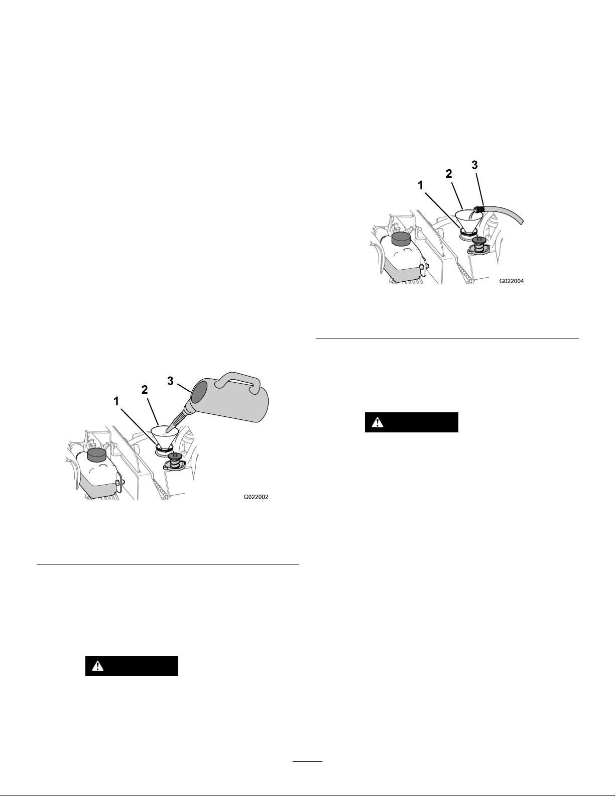
6.Openthedrainplugfortheradiatorandallowthe
coolantsystemtodraincompletely.
E.Openthedrainplugfortheradiator,anddrain
thecleaningsolutionintoadrainpan.
Note:Disposeoftheusedcoolantproperlyaccording
tolocalcodes.
7.Cleanthethreadsonthedrainplugandapply3layers
ofPTFEsealingtape.
8.Closethedrainplug(Figure138).
FlushingtheCoolingSystem
Engineandradiatorcoolantcapacity:16.8L(17.7USqt)
1.Parkthemachineonalevelsurface,stoptheengine,
andremovetheignitionkey.
2.Conditionthecoolingsystemasfollows:
A.Ensurethatthecoolantisdrainedfromthe
radiatorandthatthedrainplugisclosed;referto
CheckingtheCoolingSystem(page57).
B.Addacoolingsystemcleaningsolutiontotheto
theradiatorthroughthellerneck(Figure139).
Note:Usecleaningsolutionof21g(12ozdry)
ofsodiumcarbonateforevery17L(18USqt)
ofwater;otherwise,useacommerciallyavailable
equivalent.Followthedirectionsthatcomewith
thecleaningsolution.
F.Cleanthethreadsonthedrainplugandapply3
layersofPTFEsealingtape.
G.Closethedrainplug.
3.Flushthecoolingsystemasfollows:
A.Opentheller-neckcap.
B.Filltheradiatorwithcleanwater(Figure140).
Figure140
1.Fillerneck
2.Funnel
C.Closetheller-neckcap.
D.Operatetheenginefor5minutesoruntilthe
coolanttemperatureindicates82°C(180°F),and
thenstoptheengine.
3.Cleanwater
Figure139
1.Fillerneck(radiator)3.Coolantsystemcleaning
solution
2.Funnel
C.Closethedrainplug(Figure138).
Important:Donotinstalltheradiatorcap.
D.Operatetheenginefor5minutesoruntilthe
coolanttemperatureindicates82°C(180°F),and
thenstoptheengine.
CAUTION
Thecleaningsolutionishotandcan
causeburns.
CAUTION
Thewaterishotandcancauseburns.
Stayawayfromthedischargeendofthe
coolantdrainplug.
E.Openthedrainpluganddrainthewaterintoa
drainpan.
F.Cleanthethreadsonthedrainplugandapply3
layersofPTFEsealingtape.
G.Ifthewaterdrainedfromtheradiatorisdirty,
performsteps3-Athrough3-Euntilthewater
drainedfromtheradiatorisclean.
H.Closethedrainplug(Figure138).
Stayawayfromthedischargeendofthe
coolantdrain.
94
Page 95
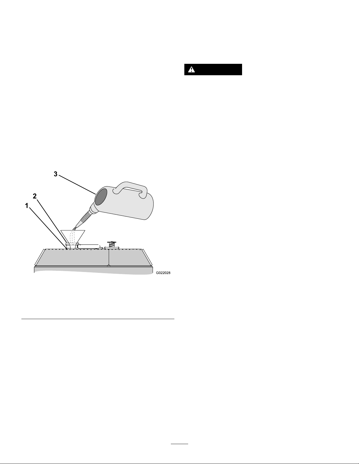
FillingtheSystemwithCoolant
G022028
1
2
3
Important:Youmustllthecoolingsystemproperlyto
preventairlocksinthecoolingpassages.Failingtovent
thecoolingsystemproperlycanseverelydamagethe
coolingsystemandengine.
Important:Useamixtureof50%ethyleneglycoland
50%watermixtureorequivalentinthemachine.The
lowestambientoperatingtemperatureforthismixture
isabove-37°C(-34°F).Iftheambienttemperatureis
lower,adjustthemixture.Useamixtureofethylene
glycolandwaterorequivalentinthemachineallyear.
1.Parkthemachineonalevelsurface,stoptheengine,
andremovetheignitionkey.
BeltMaintenance
ServicingtheEngine-drive
Belt
WARNING
Contactingarotatingbeltcancauseseriousinjury
ordeath.
Stoptheengineandremovetheignitionkeybefore
workingnearbelts.
2.Removetheradiatorcap(Figure137).
3.Filltheradiatorwithcoolantuntiltheuidlevelisup
tothebottomofthellerneck(Figure141).
Note:Thecoolantcapacityofboththeengineand
theradiatoris16.8L(17.7USqt).
Figure141
1.Coolantlevel(atthe
bottomofthellerneck)
2.Fillerneck
3.Coolant(50/50ethylene
glycolandwateror
equivalent)
CheckingtheConditionoftheBelt
ServiceInterval:Every250hours
1.Parkthemachineonalevelsurface,stoptheengine,
andremovetheignitionkey.
2.Openthefronthood;refertoOpeningtheFront
Hood(page72).
3.Inspectthebeltforcuts,cracks,loosecords,grease,oil,
twisting,orsignsofabnormalwear(Figure142).
Note:Replacethebeltifitisexcessivelywornor
damaged.
4.Installtheradiatorcap(Figure137).
5.Fillthecoolantreservoirwithcoolantuntilitisfull.
6.Installthecoolantreservoircap.
7.Starttheengineandrunitathalfthrottlefor5minutes.
8.Stoptheengineandremovethekey.
9.Wait30minutes,thenchecktheuidlevelinthe
coolantreservoir.Ifitislow,addcoolant.
95
Page 96
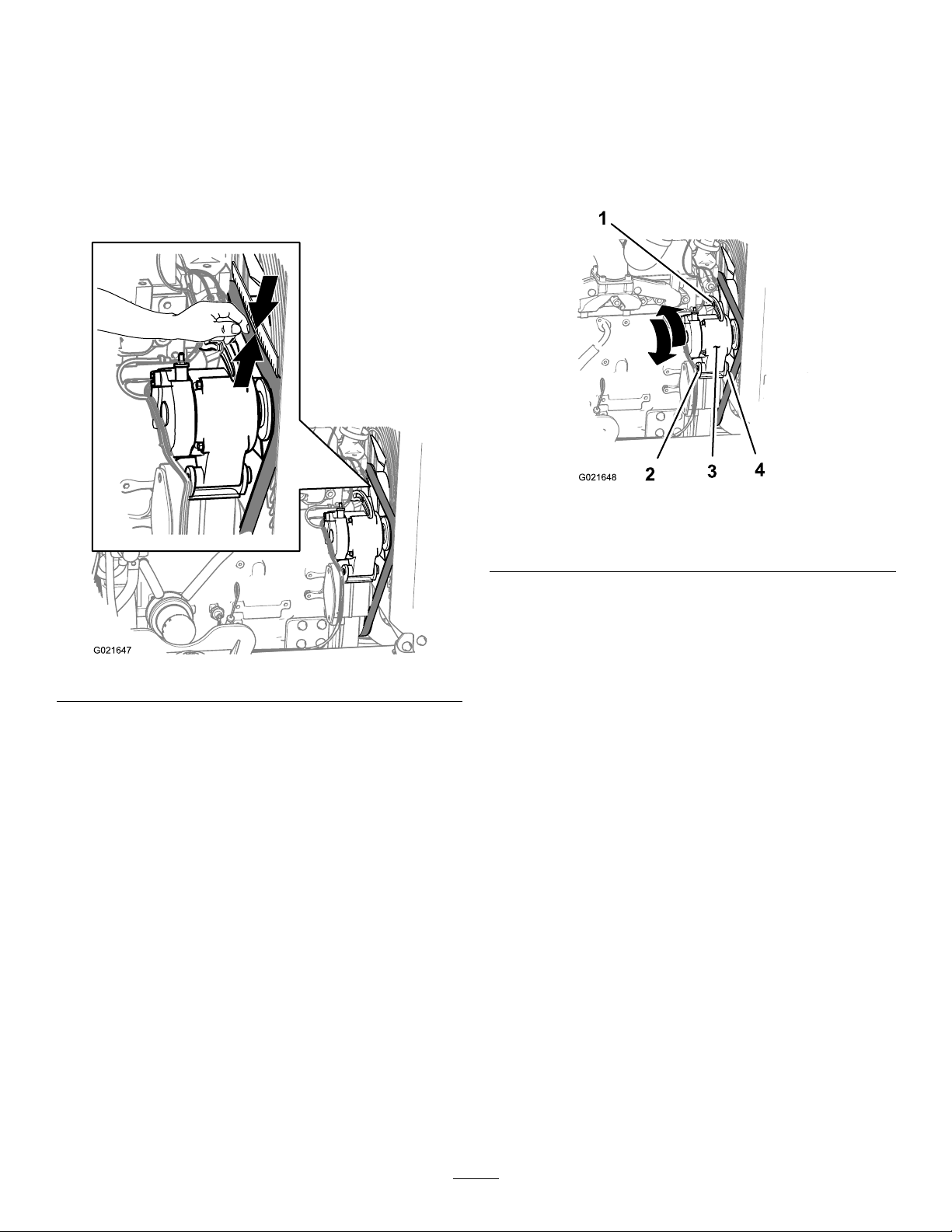
CheckingtheTensionoftheBelt
AdjustingtheTensionoftheBelt
ServiceInterval:Every1,000hours
1.Parkthemachineonalevelsurface,stoptheengine,
andremovetheignitionkey.
2.Openthefronthood;refertoOpeningtheFront
Hood(page72).
3.Alignastraightedgeoverthedrivebeltandacrossthe
pulleysasshowninFigure142.
1.Parkthemachineonalevelsurface,stoptheengine,
andremovetheignitionkey.
2.Openthefronthood;refertoOpeningtheFront
Hood(page72).
3.Loosenthenutandboltatthepivotpointforthe
alternator(Figure143).
Figure143
1.Adjustmentbolt3.Alternator
2.Nut(alternatorpivotpoint)4.Bolt(alternatorpivotpoint)
Figure142
4.Pressthebeltdownatthemidwaypointbetweenthe
fanpulleyandthealternatorpulleyasshowninFigure
142.
Note:Therangeofbeltdeectionbetweenthe
straightedgeandthebeltshouldbe7to9mm(0.28to
0.35inches),underaloadof10kg(22lb).
5.Ifthetensionofthebeltisaboveorbelowthespecied
range,adjustthedrivebelttension;refertoAdjusting
theTensionoftheBelt(page96).
4.Loosentheadjustmentboltonthealternator(Figure
143).
5.Movethealternatorawayfromtheenginetoincrease
thebelttension;movethealternatortowardtheengine
todecreasethebelttension(Figure143).
6.Tightenthealternatoradjustmentbolt(Figure143).
7.Checkthetensionofthebelt;refertoCheckingthe
TensionoftheBelt(page96).
8.Ifthebelttensioniscorrect,tightenthenutandbolt
atthepivotpointforthealternator(Figure143);
otherwiserepeatsteps4through7.
96
Page 97
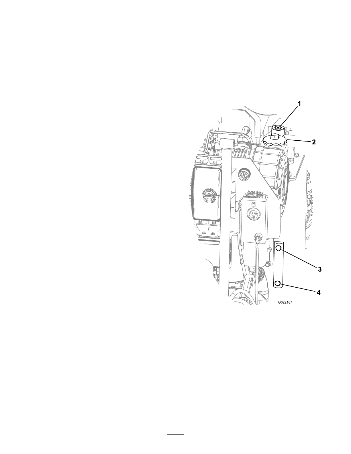
HydraulicSystem
1
2
3
4
G022167
Maintenance
CheckingtheHydraulicFluid
ServiceInterval:Beforeeachuseordaily
Checkthehydraulicuidasfollows:
ServicingtheHydraulicFluid
Thehydraulicreservoirislledatthefactorywith
approximately102L(27USgallons)ofhigh-qualityhydraulic
uid.Checkthelevelofthehydraulicuidbefore
theengineisrststartedanddailythereafter.The
recommendedreplacementuidfollows:
ToroPremiumAllSeasonHydraulicFluid(Availablein
5gallonpailsor55gallondrums.ContactyourAuthorized
ToroDealerforpartnumbers.)
Alternateuids:IftheTorouidisnotavailable,other
uidsmaybeusedprovidedtheymeetallthefollowing
materialpropertiesandindustryspecications.W edonot
recommendtheuseofsyntheticuid.Consultwithyour
lubricantdealertoidentifyasatisfactoryproduct.
Note:Torowillnotassumeresponsibilityfordamage
causedbyimpropersubstitutions,souseonlyproducts
fromreputablemanufacturerswhowillstandbehindtheir
recommendation.
HighViscosityIndex/LowPourPoint
Anti-wearHydraulicFluid,ISOVG46
1.Parkthemachineonalevelsurface,stoptheengine,
andremovetheignitionkey.
2.Openthefronthood;refertoOpeningtheFront
Hood(page72).
3.Lookatthesightgaugeonthehydraulictankandcheck
theleveloftheoil(Figure144).
MaterialProperties:
42.2cStat40°C(104°F) Viscosity,ASTMD445
7.8cStat100°C(212°F)
ViscosityIndexASTM
D2270
PourPoint,ASTMD97-6°C(-42°F)
IndustrySpecications:VickersI-286-S(QualityLevel),
Note:Manyhydraulicuidsarealmostcolorless,makingit
difculttospotleaks.Areddyeadditiveforthehydraulic
systemoilisavailablein20mL(2/3oz)bottles.Onebottle
issufcientfor15-22L(4-6gallons)ofhydraulicoil.Order
partno.505-150fromyourAuthorizedToroDealer.
Note:Ifambientoperatingtemperaturesexceed43°C(110°
F),contactToroforuidrecommendations.
VickersM-2950-S(Quality
Level),DenisonHF-0
158
Figure144
1.Hydraulic-tankbreather
2.Hydraulic-tankcap
3.Fulloillevel
4.Lowoillevel
4.Ifthelevelislow,openthehydraulic-tankcap,andadd
theappropriateuiduntilitreachesFullonthesight
gauge(Figure144).
5.Installcapontothellerneck.
97
Page 98
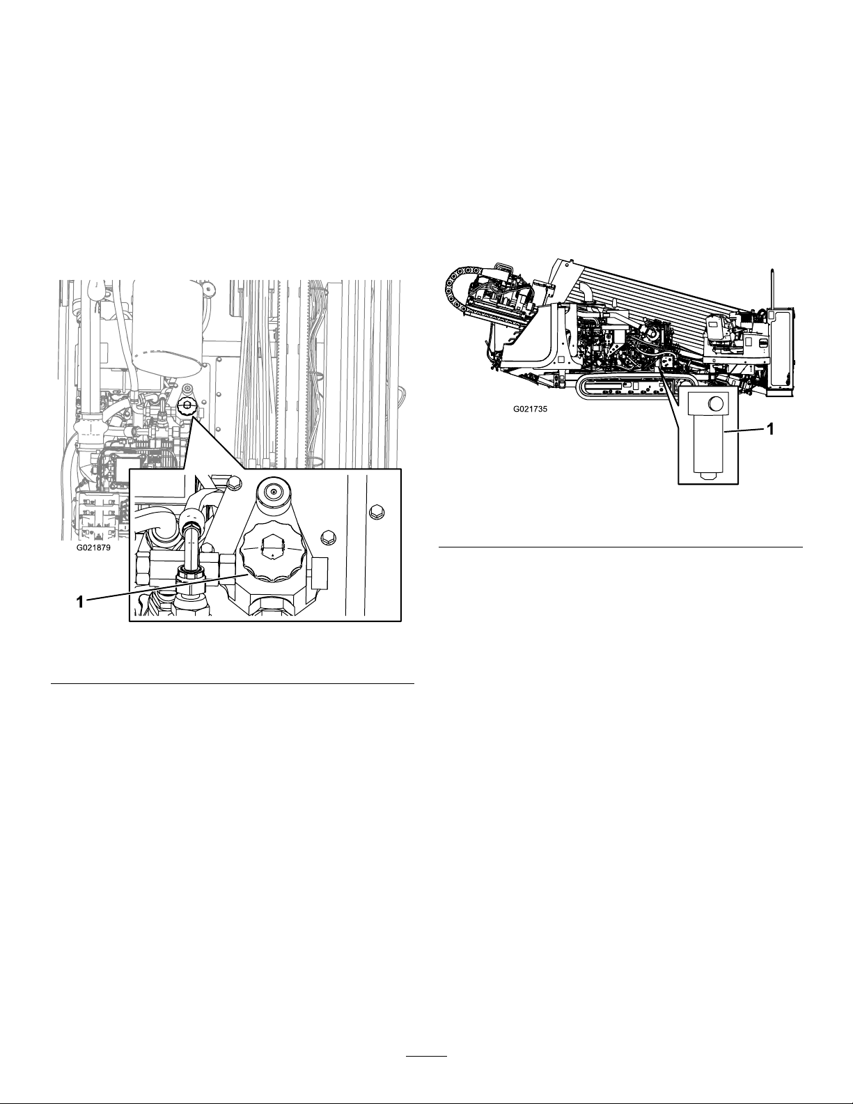
ChangingtheHydraulic-uidReturn
Filter
ServiceInterval:Every500hours/Every6months
(whichevercomesrst)
1.Parkthemachineonalevelsurface,stoptheengine,
andremovetheignitionkey.
2.Openthefronthood;refertoOpeningtheFront
Hood(page72).
3.Cleantheareaaroundthellerneckandcapofthe
hydraulictank.
4.Openthehydraulic-tankcap(Figure145).
ChangingtheHydraulic-pressureFilter
ServiceInterval:Every500hours/Every6months
(whichevercomesrst)
1.Parkthemachineonalevelsurface,stoptheengine,
andremovetheignitionkey.
2.Openthefronthood;refertoOpeningtheFront
Hood(page72).
3.Placeadrainpanunderthelter.
4.Usingalterwrench,removethehydraulic-pressure
lter(Figure146).
Figure145
1.Hydraulic-tankcap
5.Discardtheoldhydraulic-uidreturnlter.
6.Installanewhydraulic-uidreturnlter.
Figure146
1.Hydraulic-pressurelter
5.Discardtheoldlter.
6.Applyathinlayerofhydraulicoiltotheo-ringofthe
lter.
7.Installandtightenthenewlterwithalterwrench.
8.Starttheengine,letitrunidleforapproximately
1minute,thencheckforleaksaroundthe
hydraulic-pressurelter.
ChangingtheHydraulicFluid
ServiceInterval:Every1,000hours/Yearly(whichever
comesrst)
Important:Iftheuidbecomescontaminated,contact
yourAuthorizedToroDealer,becausethesystemmust
beushed.Contaminateduidlooksmilkyorblack
whencomparedtocleanoil.
Important:Useofanyotherltermayvoidthewarranty
onsomecomponents.
1.Parkthemachineonalevelsurface,stoptheengine,
andremovetheignitionkey.
2.Openthefronthood;refertoOpeningtheFront
Hood(page72).
3.Raisethemachineusingproperequipment.
98
Page 99

WARNING
Raisingtherearoftheunitrelyingsolely
onmechanicalorhydraulicjackscouldbe
dangerous.Themechanicalorhydraulic
jacksmaynotbeenoughsupportormay
malfunctionallowingtheunittofall,which
couldcauseinjuryordeath.
Do not
jacksforsupport.
Useadequatejackstandsorequivalent
support.
4.Placealargedrainingcontainerunderthehydraulic
uidtank.
5.Removethedrainplugfromthebottomofthetank.
6.Cleanthethreadsonthedrainplugandapply3layers
ofPTFEsealingtape.
7.Drainthehydraulicuidowintothecontainer.
Important:Thecapacityofthehydraulic-uid
tankis102L(27USgallons),soensurethatyou
haveacontainerofatleast114L(30USgallons)
todraintheuidinto.
8.Installthedrainplugwhenthehydraulicuidstops
draining.
9.Cleantheareaaroundtheltermountingareas.
relysolelyonmechanicalorhydraulic
Inspectthehydrauliclinesandhosesdailyforleaks,kinked
lines,loosemountingsupports,wear,loosettings,weather
deterioration,andchemicaldeterioration.Makeallnecessary
repairsbeforeoperating.
WARNING
Hydraulicuidescapingunderpressurecan
penetrateskinandcauseinjury.
•Makesurethatallhydraulicuidhosesand
linesareingoodconditionandallhydraulic
connectionsandttingsaretightbefore
applyingpressuretothehydraulicsystem.
•Keepyourbodyandhandsawayfrompin
holeleaksornozzlesthatejecthighpressure
hydraulicuid.
•Usecardboardorpapertondhydraulicleaks.
•Safelyrelieveallpressureinthehydraulicsystem
beforeperforminganyworkonthehydraulic
system.
•Seekimmediatemedicalattentionifuidis
injectedintoskin.
HydraulicSystemTestPorts
Thetestportsareusedtotestthepressureinthehydraulic
circuits.ContactyourAuthorizedToroDealerforassistance.
10.Placeadrainpanunderthelterandremovethelter
(Figure145).
11.Lubricatetheltergasketofeachnewlterandll
themwithhydraulicuid.
12.Ensurethattheltermountingareasareclean.
13.Screwtheltersonuntilthegasketscontactsthe
mountingplates;thentightenthelteranadditional
1/2turn.
14.Fillthereservoirwithhydraulicuid.
Important:Useonlythehydraulicuids
specied.Otheruidscouldcausesystem
damage.
15.Installthereservoircap.Starttheengineanduseall
ofthehydrauliccontrolstodistributehydraulicuid
throughoutthesystem.Alsocheckforleaks;thenstop
theengine.
16.Checktheuidlevelandaddenoughtoraiselevelthe
leveltotheFullmarkonthedipstick.Donotoverll.
CheckingtheHydraulicLinesand
Hoses
ServiceInterval:Every2years—Replacemovinghoses.
99
Page 100
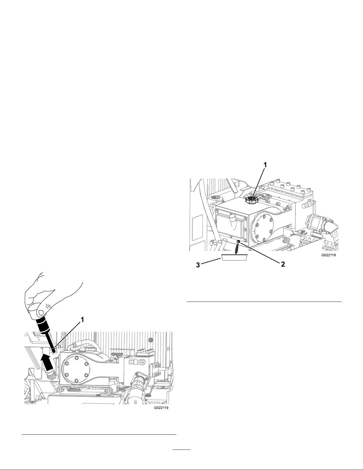
Drilling-uidPump
1
G0221 19
1
2
3
G0221 18
4.Ensurethattheoilisattheoil-lllineasshownin
Figure147.
Maintenance
Servicingthe
Drilling-uid-pumpOil
Thedrilling-uidpumpisshippedwithoilinthecrankcase;
however,checktheoillevelbeforeandafteryourststart
theengine.
Thecrankcasecapacityis1.9L(2USqt).
Useonlyhigh-qualityengineoilthatmeetsthefollowing
specications:
•APIClassicationLevelRequired:CH-4,CI-4or
higher
•Oil:SAE30-weight,non-detergentoilabove0°C(32°F)
ToroPremiumEngineOilisavailablefromyourdealer.See
thepartscatalogforpartnumbers.Also,refertotheEngine
Operator'sManual,includedwiththemachine,forfurther
recommendations.
CheckingtheDrilling-uid-pumpOil
Level
Note:Iftheoilisbelowtheoil-llline,refertostep
8ofChangingtheDrilling-uidPumpOil(page100)
andaddthenecessaryamountofoil.
ChangingtheDrilling-uidPumpOil
ServiceInterval:Every500hours—Changethedrilling-uid
pumpoil.
1.Parkthemachineonalevelsurface,stoptheengine,
andremovetheignitionkey.
2.Opentherearhood;refertoOpeningtheRear
Hood(page73).
3.Allowtheenginetocool.
4.Removethedrainplugandplaceadrainpanunderthe
drain-plughole(Figure148).
ServiceInterval:Beforeeachuseordaily—Checkthe
drilling-uid-pumpoillevel.
1.Parkthemachineonalevelsurface,stoptheengine,
andremovetheignitionkey.
2.Opentherearhood;refertoOpeningtheRear
Hood(page73).
3.Removetheoildipstick(Figure147).
Figure148
1.Oil-llercap
2.Drainplug
5.Cleanthethreadsonthedrainplugandapply3layers
ofPTFEsealingtape.
6.Allowalloftheoiltodrainfromdrainplugintothe
oilpan(Figure148).
7.Installthedrainplug.
8.Removetheoil-llercap(Figure148)andadd
approximately1.9L(2qt)ofoil,oruntiltheoilreaches
theoil-lllineonthedipstickasshowninFigure147.
3.Drainpan
Figure147
1.Oil-llline
100
 Loading...