

Trailer
TRXTrencherorSTXStumpGrinder
ModelNo.22979
ModelNo.22979HD
FormNo.3432-587RevA
SetupInstructions
Safety
Readandunderstandthefollowingbeforeusingthe
trailer.
•Beforeeveryuse:
–Inspectthecoupler,ball,andhitch.
–Alwaysusesafetychains.
–Verifythatalllightsarefunctioningproperly.
–Verifythatthetiresareproperlyinatedas
recommendedontires.
–Verifythatthelugnutsaretightandtorqued
properly.
–Verifythatthatthemachineisproperlysecured.
•Knowhowtoproperlycontrolyourtowing
vehicle/trailercombinationonthehighwayunder
SafetyandInstructionalDecals
allconditions.Rememberthattheloadedweight
ofthetrailerincreasesyourbrakingandstopping
distances.
•Youareresponsiblefordeterminingthetowing
capacityofyourvehicle.
•Cleanoffthemachinespriortoloadingthem
ontothetrailer.Keepthetrailercleanofloose
debristhatcouldfalloffduringtransport,causinga
hazard.
•Useproperloadingandunloadingprocedures
andsequences.Readallmanualsandfollowthe
instructionsprovided.
•Inspectthetrailerandmachineoftenduring
transport.
Safetydecalsandinstructionsareeasilyvisibletotheoperatorandarelocatednearanyarea
ofpotentialdanger.Replaceanydecalthatisdamagedormissing.
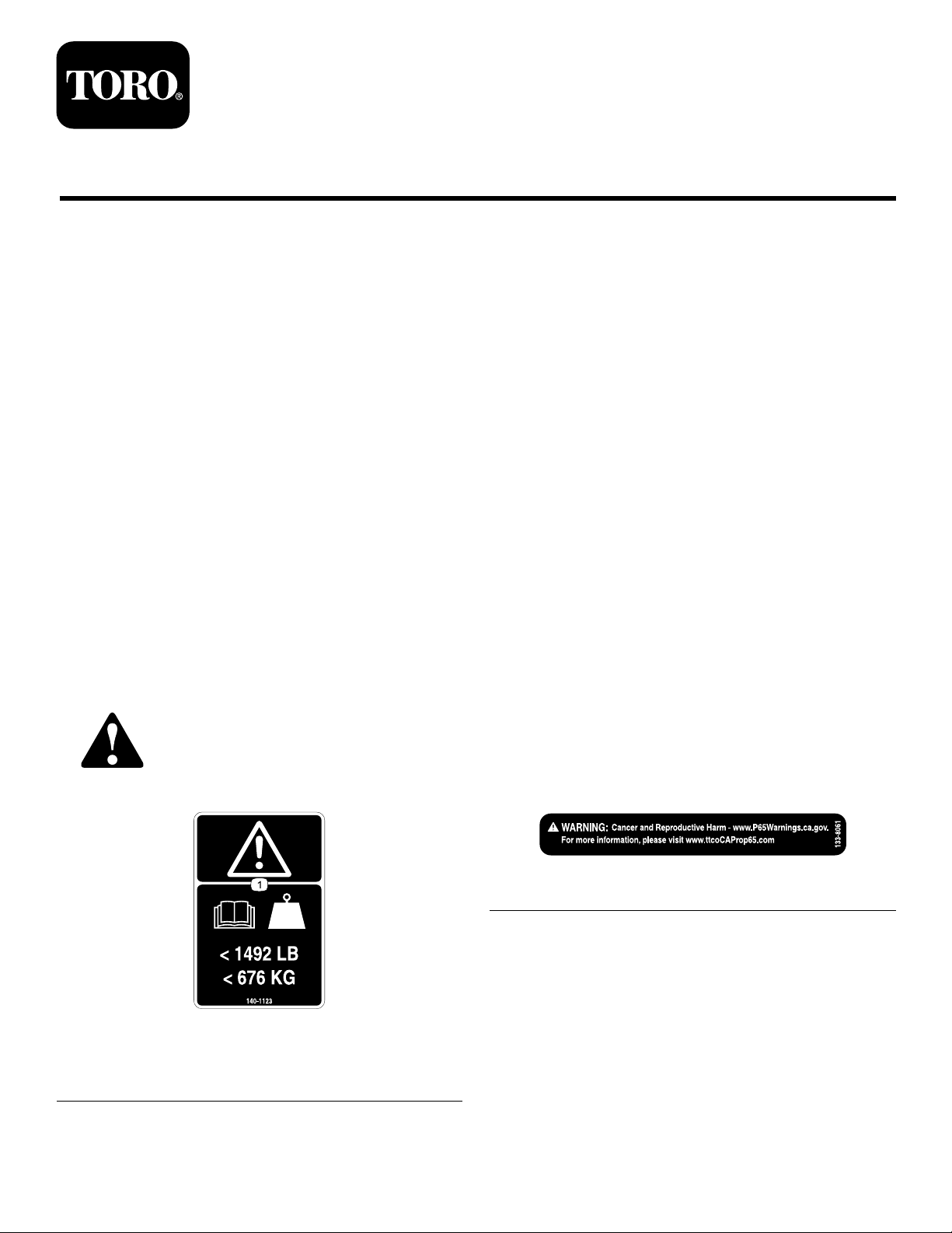
140-1123
1.Warning—readtheOperator’sManual;maximumweight
of676kg(1,492lb).
©2019—TheT oro®Company
8111LyndaleA venueSouth
Bloomington,MN55420
Registeratwww.T oro.com.
decal140-1123
133-8061
OriginalInstructions(EN)
PrintedintheUSA.
AllRightsReserved
decal133-8061
*3432-587*A

Setup
LooseParts
Usethechartbelowtoverifythatallpartshavebeenshipped.
ProcedureDescription
1
2
3
4
5
Trailerbed1
Wheel2
Lugnuts10
Tongue1
Bolt(5/8x3inches)
Nut(5/8inch)
Mountingstrap2
Jack1
Bolt4
Locknut4
Chain
Ramp1
Bolt(1/2x1-1/2inches)
Nut(1/2inch)
Rampstrap2
Cotterpin(1-1/4inch)
Nopartsrequired
Qty.
Use
Installthewheels.
2
2
1
2
2
2
–
Attachthetongue.
Installthetrailerjack.
Installtheramp.
Testthewireharness.
1
InstallingtheWheels
Partsneededforthisprocedure:
1Trailerbed
2Wheel
10Lugnuts
Procedure
1.Usingahoistormechanicaljack,raisethetrailer
bed.
2.Installthewheelsontothehubwiththevalve
stemfacingouttoallowaccess(Figure1).
g008362
Figure1
1.Lugnut4.Hub
2.Wheel5.Posts
3.Valvestem
3.Secureeachwheeltothehubusing5lugnuts.
Torquethenutsto68-102N∙m(50-75ft-lb).
4.Whilethebedisstillraised,removethefasteners
securingthepackingstandstothetrailerbed.
5.Lowerthebedtothegroundandverifythecold
pressureofthewheelsisatamaximumof551
kPa(80psi).
2

2
AttachingtheTongue
Partsneededforthisprocedure:
1Tongue
2
Bolt(5/8x3inches)
2
Nut(5/8inch)
Procedure
1.Laythetongueoutinfrontofthetrailerand
locateaexiblewirelongerthanthetongue.
2.Feedthewirethroughthelengthofthetongue
soaportionofthewireisvisibleatbothends
(Figure2).
g008364
Figure3
1.Tongue3.Wireharness
2.Opening4.Wire(securedtoharness)
5.Usingajackorhoist,raisethefrontendofthe
trailerbedtoallowtheinstallationofthetongue
(Figure4).
g008365
Figure4
Figure2
1.Tongue
2.Opening5.Harness(fromtrailer)
3.Wire
3.Removethefastenersecuringthehitchwiring
bundledtothetrailerbed.
4.Securethewireinthetonguetothewiring
harnessonthetrailerandpullthewiringharness
throughthelengthofthetongueusingthewire
(Figure3).Removethewirefromtheharness.
4.Tongue(trailerside)
1.Jack2.Trailer
6.Movethetongueintopositionunderthetrailer
bedandraiseittoaligntherearholesinthe
trailerbedwiththerearholesintongue.
g008363
7.Withthehelpofanotherperson,installabolt
(5/8x3inches)throughtheholes.Raisethe
frontendofthetonguetoalignthefrontholes
anduseabolt(5/8x3inches)toholdthetongue
inplace(Figure5).
3

3
InstallingtheTrailerJack
(Model22979)
Partsneededforthisprocedure:
Figure5
1.Trailer(underside)
2.Tongue
3.Boltholes
8.Atthefrontendofthetongue,pullthewire
harnessforwardtoremoveallslackinthe
harnessbeforecontinuingtheinstallation.
4.Wireharness
5.Bolt(5/8x3inches)
Important:Ensurethatthewireharnessis
notbeingpinchedorimpingedduringthe
installation.Damagedwirescancausethe
taillightstomalfunction.
9.Securetheboltswith2nuts(5/8inch)(Figure6).
Torquethenutsto103-135N∙m(76-100ft-lb).
g008366
2Mountingstrap
1Jack
4Bolt
4Locknut
Procedure
1.Placethejackagainstthetongue(Figure7).
Figure6
1.Trailerandtongue
2.Bolt(5/8x3inches)
10.Lowerthefrontendofthetrailer.
3.Nut(5/8inch)
g022032
Figure7
g008367
1.Locknuts(4)3.Bolts(4)
2.Mountingstraps
2.Positionthe2mountingstrapsontheotherside
ofthetongue(Figure7).
3.Securethejackandthe2mountingstrapstothe
tongueusing4boltsand4locknuts(Figure7).
4.Torquethelocknutsto33.9N∙m(25ft-lb).
4

4
InstallingtheRamp
Partsneededforthisprocedure:
1
Chain
1Ramp
2
Bolt(1/2x1-1/2inches)
2
Nut(1/2inch)
2Rampstrap
2
Cotterpin(1-1/4inch)
Procedure
1.Installtheretainingchainfromthebedofthe
trailertotheretainingpin(Figure8).
Figure8
1.Trailerbed4.Retainingpin
2.Loop
3.Chain
5.Keeper(attached)
2.Withthehelpofanotherperson,placetheramp
intopositionattheendofthetrailerbed.Usea
bolt(1/2x1-1/2inches)andanut(1/2inch)at
eachhingetoattachtheramptothetrailerbed
(Figure9).
g008369
Figure9
1.Trailerbed
2.Ramp
3.Bolt(1/2x1-1/2inches)
g008368
3.Tightentheboltuntilthereisapproximatelya
4.Nut(1/2inch)
5.0.16cm(1/16inch)gap
0.16cm(1/16inch)gapbetweenthebedand
ramphinges.Thisallowstheramptomove
freelywhilesecurelyfastenedtothetrailer.
Important:Donotovertightentheramp
pivotboltsorbindingwilloccur,causing
damagetothetrailer.
4.Installarampstraptoeachsideofthetraileras
showninFigure10.Installacotterpinandbend
backtheendstosecurethestrapstothetrailer.
5

Figure10
1.Lynchpin4.Ramp
2.Postonramp5.Postonbed
3.Rampstrap
5.Raisetherampandusethestrapsandlynch
pinstosecureitinthetransportposition(Figure
10).
6.Cotterpin
5
TestingtheWireHarness
NoPartsRequired
Procedure
g008372
g008371
1.Tongue3.Wiringharness
2.Holster
Figure11
Operation
OperatingtheJack
Turnthecrankclockwisetolowerthejack(Figure12).
1.Locatethewhitegroundwireonthewiring
harnessandgroundboltonthefrontofthe
tongue.Securethegroundwiretothetongueat
thegroundbolt.Donotovertightenthebolt.
2.Plugtheatconnectortoasuitablevehiclefor
testing.Checktomakesurethebrakelights
illuminateproperlywiththebrakepedalapplied
andthetaillightsashwhentheturningsignals
areuse.
3.Disconnectthewireconnectorandbundleitto
thetrailer.Storetheatconnectortotheholster
onthetongue(Figure1 1).
g022033
Figure12
Turnthecrankcounterclockwisetoraisethejack
(Figure13).
6

Figure13
Pulloutonthehandletorotatethejack(Figure14).
AttachingtheTrailer
Thistrailerusescouplersthatrequirea2inchball
forthehitch.
1.Rotatethejackintotheverticalposition(Figure
14).
2.Raisethetrailertoabovetheballhitch.
3.Liftthehandleonthetongue.
4.Lowerthetongueballsocketovertheballhitch
(Figure15).
g022034
g008373
Figure15
1.Tongue4.Auxiliarychains
2.Ballsocket
3.Handle,lockedposition
5.Lockingpin(notincluded
withthetrailer)
5.Closethehandle,makingsureitissecurely
locked.
6.Installapin(notincludedwiththetrailer)tolock
thehandle.
7.Attachthechainstoholesonthevehiclehitch.
Connectthewiringharnesstotheatconnector
onthehitch.
8.Raisethejackoffofthegroundandrotatethe
jackintothehorizontalposition.
g02211 1
Figure14
1.Handle
7
LoadingtheTrencher
CAUTION
Attemptingtoloadorunloadthemachine
fromatrailerthatisnotsecurelyhitchedto
asuitablevehiclecouldcausethetrailerto
becomeunstable,andtipcausinginjuryto
youorbystanders.
Makesurethetrailerissecurelyhitchedto
asuitablevehicleparkedonalevelsurface
beforeattemptingtoloadorunloadthe
machine.
1.Removetheretainingstrapsandlowertheramp
totheground.
2.Removethetiedownbarpinandslidethebars
apart(Figure16).
Important:Allowthepinandchaintolayon
thecenterofthebedtoavoidrunningoverit
withthemachineanddamagingit.
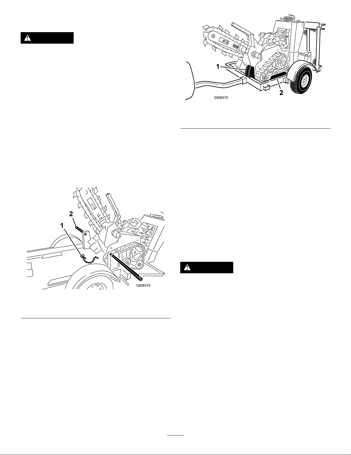
Figure17
1.Forwardstop
7.Turnthemachineoffandengagetheparking
brake.
8.Lowerthetrencherarmuntilitrestsonthefront
stop.
2.Guiderails
Note:Makesurethefrontcrosstubeofthe
trencherisfullyengagedtothefrontstopon
thetrailer.
g008375
Figure16
1.Tiedownbar2.Retainingpin
3.Startthetrencheraccordingtothedirectionsin
theOperator'sManualandruntheengineat
lowspeed.
4.Withthetrencherarmraisedinthetransport
positiondrivethemachineuptherampontothe
trailerbed.
5.Takecaretoloadthetrencherwiththetracks
betweenguiderailsonthetrailerbed(Figure
17).
9.Slidethetiedownbarstogetherthroughtherear
tiedownloops,aligningtheholestoallowfor
theretainingpin.Installthepin.
10.Raisetherampandusethestrapsandlynch
pinstosecureitinthetransportposition.
UnloadingtheTrencher
CAUTION
Attemptingtoloadorunloadthemachine
g008374
fromatrailerthatisnotsecurelyhitchedto
asuitablevehiclecouldcausethetrailerto
becomeunstable,andtipcausinginjuryto
youorbystanders.
Makesurethetrailerissecurelyhitchedto
asuitablevehicleparkedonalevelsurface
beforeattemptingtoloadorunloadthe
machine.
1.Removelynchpinssecuringtherampstraps.
Removethestrapsandslowlylowertheramp
totheground.
6.Movethetrencherforwardslowlyuntilthefront
ofthemachinemeetstheforwardstoponthe
trailerbed.
8

DANGER
Therampinthetransportposition
representsastoredenergyhazardand
ifnotsecuredcanfall;injuringyouor
bystanders.
Holdtherampinplacewhenremoving
strapsandusecaretolowertheramp
carefullytotheground.
2.Removethepinontheholddownbarandlay
thechainandpinonthecenterofthetrailerbed.
Slidetheholddownbarsapart.
3.StartthemachineaccordingtotheOperator's
Manualanddisengagetheparkingbrake.
4.Raisethetrencherarmintothetransport
position.
5.Slowly,whilelookingbehindyouanddown,
movethemachinedownandofftheramp.
RemovingtheTrailerHitch
1.Parkthemachineandtraileronalevelsurface.
2.Rotatethejackintotheverticalposition.
3.Disconnectthewiringharnessfromtheelectrical
connectoronthehitch.Placetheconnectorinto
theholsteronthetongue.
4.Removethechainsretainingthetonguetothe
hitch.
5.Removethepinandliftthehandleontopofthe
hitch.
6.WiththetonguehandleraisedCHECK.
7.Raisethetongueabovethehitchandlowerthe
handle
8.Installapin(notincluded)tolockthehandle.
9.Chockthetrailerwheels.
Maintenance
CheckingLugNuts
ServiceInterval:Aftertherst10hours/Monthly
(whichevercomesrst)
Torquethenutsto68-102N∙m(50-75ft-lb).
9

Notes:

Notes:

 Loading...