

Page 1
Form No. 3323-258
Hydraulic
Blade
Sitework Systems Attachment
Model No. 22414—890001 & Up
Operator’s Manual
English (CE)
Page 2
Contents
Page
Introduction 2.
Safety 2
Safety Decals3. . . . . . . . . . . . . . . . . . . . . . . . . . . . .
Specifications 3
Stability Ratings3. . . . . . . . . . . . . . . . . . . . . . . . . . .
Operation 3
T
ips for Using the Blade4. . . . . . . . . . . . . . . . . . . .
Blade Operation and Controls4. . . . . . . . . . . . . . . .
Maintenance 4
Service Interval Chart4. . . . . . . . . . . . . . . . . . . . . .
Checking the Blade Cutting Edge4. . . . . . . . . . . . .
Storage 4
Troubleshooting 5
. . . . . . . . . . . . . . . . . . . . . . . . . . . . . . . .
. . . . . . . . . . . . . . . . . . . . . . . . . . . . . . . . . . . . . .
. . . . . . . . . . . . . . . . . . . . . . . . . . . . . . . .
. . . . . . . . . . . . . . . . . . . . . . . . . . . . . . . . . . .
. . . . . . . . . . . . . . . . . . . . . . . . . . . . . . . . .
. . . . . . . . . . . . . . . . . . . . . . . . . . . . . . . . . .
. . . . . . . . . . . . . . . . . . . . . . . . . . . . . .
Introduction
W
e want you to be completely satisfied with your new
product, so feel free to contact your local Authorized
Service Dealer for help with service, genuine replacement
parts, or other information you may require.
Whenever you contact your Authorized Service Dealer or
the factory
your product. These numbers will help the Service Dealer
or Service Representative provide exact information about
your specific product. Y
number on a plate located on the blade pivot frame.
For your convenience, write the product model and serial
numbers in the space below
, always know the model and serial numbers of
ou will find the model and serial
.
Model No:
DANGER
serious injury or death if the recommended precautions
are not followed.
WARNING
or death if the recommended precautions are not followed.
CAUTION
moderate injury if the recommended precautions are not
followed.
wo other words are also used to highlight information.
T
“Important” calls attention to special mechanical
information and “Note” emphasizes general information
worthy of special attention.
The left and right side of the machine is determined by
standing in the normal operator’s position.
signals an extreme hazard that will cause
signals a hazard that may cause serious injury
signals a hazard that may cause minor or
Safety
Impr
oper use or maintenance by the operator or owner
can r
esult in injury
comply with the safety instructions in the traction unit
Operator’
safety alert
W
ARNING, or DANGER—“personal safety
instruction.” Failur
may r
POTENTIAL HAZARD
• Ther
WHA
•
HOW T
•
s Manual and always pay attention to the
esult in personal injury or death.
e may be buried power
telephone lines in the work ar
T CAN HAPPEN
Shock or explosion may occur
O AVOID THE HAZARD
Have the pr
buried lines and do not dig in marked ar
. T
o r
educe the potential for injury
symbol, which means CAUTION,
e to comply with the instruction
, gas, and/or
ea.
.
operty or work ar
ea marked for
eas.
,
Serial No.
The
warning system in this manual identifies potential
hazards and has special safety messages that help you and
others avoid personal injury
W
ARNING and CAUTION are signal words used to
identify the level of hazard. However
hazard, be extremely careful.
, even death. DANGER,
, regardless of the
The Toro Company – 1999
8111 Lyndale Ave. South
Bloomington, MN 55420–1196
2
All Rights Reserved
Printed in the USA
Page 3
POTENTIAL HAZARD
•
When the engine is off, attachments in the
raised position can gradually lower
WHA
T CAN HAPPEN
•
Someone nearby may be pinned or injur
the attachment as it lowers.
HOW T
•
O AVOID THE HAZARD
Always lower the attachment lift each time you
shut off the traction unit.
.
ed by
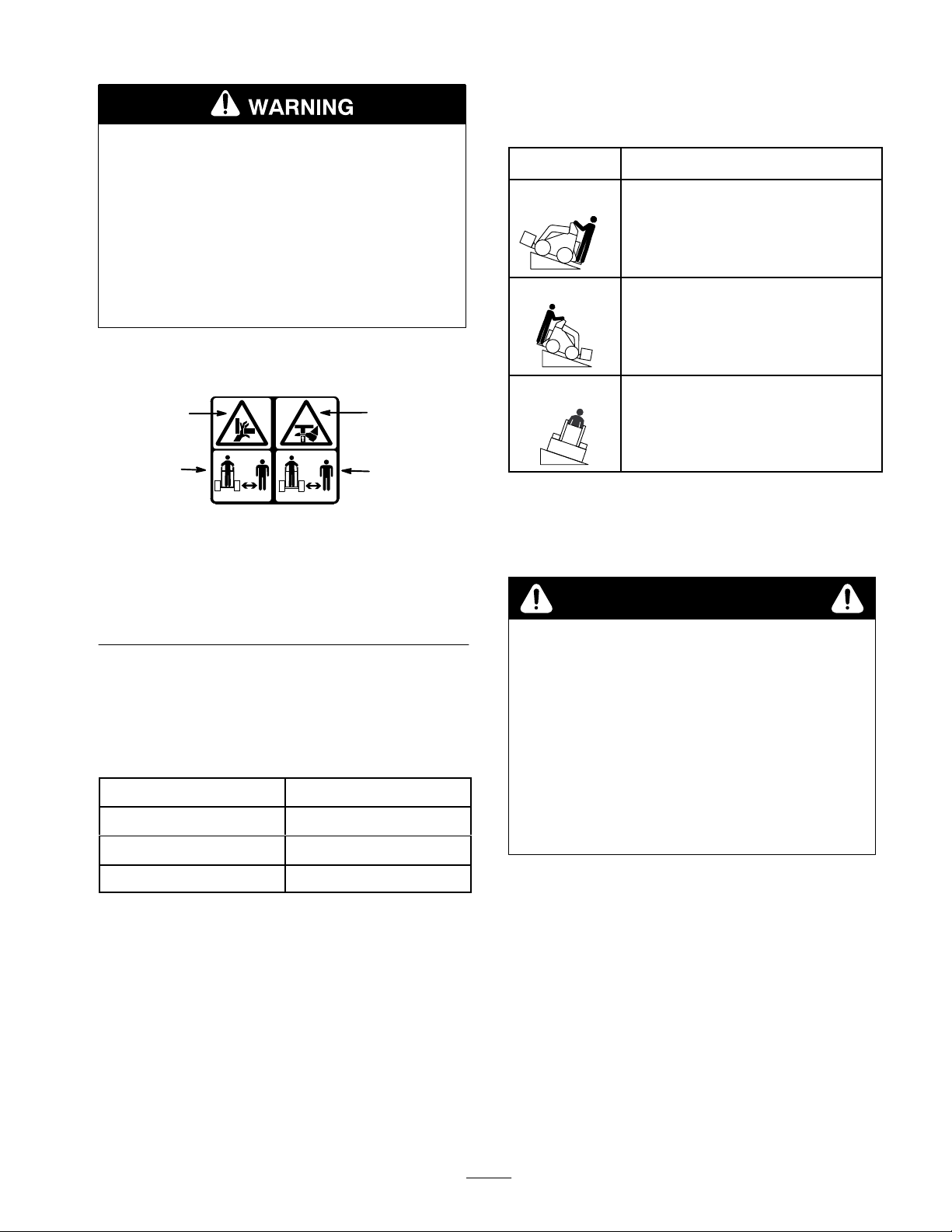
table, then find the degree of slope for the same rating and
hill position in the Stability Data section of the traction
unit operator’s manual.
Orientation
Front Uphill
Stability Rating
D
Rear Uphill
C
Safety
1. Pinching/crushing
hazard—hand
2. Pinching/crushing
hazard—foot
Decals
1
3
#
100–4650
Figure 1
3. Keep
Specifications
Note:
Specifications and design are subject to change
without notice.
Width 47.75
Length
Height
inches (121.3 cm)
25 inches (63.5 cm)
21 inches (53 cm)
2
3
bystanders away
Side Uphill
B
Note:
On traction units with a rear operator platform, the
blade is rated for use without the counterweight. If you
use the counterweight with the blade, the traction unit will
be less stable in the front and side uphill positions.
WARNING
POTENTIAL HAZARD
•
Exceeding the maximum r
can cause the traction unit to tip.
WHA
T CAN HAPPEN
•
If the traction unit tips, you or bystanders could
be crushed.
HOW T
•
O AVOID THE HAZARD
Do not drive the traction unit on a slope steeper
than the maximum r
determined in the pr
traction unit operator’s manual.
ecommended slope
ecommended slope, as
evious table and the
Weight
Stability
To
determine the degree of slope you can traverse with the
blade installed on a traction unit, find the stability rating
for the hill position you want to travel in the following
Ratings
212 lbs (96.2 Kg)
Operation
Note:
Refer to your traction unit operator’s manual for
complete instructions on installing/removing attachments
onto/from the traction unit and connecting/disconnecting
hydraulic hoses.
Note:
Always use the traction unit to lift and move the
attachment.
3
Page 4
Tips
for Using the Blade
Blade
Operation and Controls
• Clean
•
•
•
•
the area of trash, branches and rocks before
beginning work to prevent equipment damage.
Always begin with the slowest ground speed possible.
Increase speed if conditions permit.
Always use full throttle (maximum engine speed).
Never transport the blade with the loader arms raised.
Keep the arms lowered and the blade tilted up.
When scraping, leveling, and surface stripping, lower
the blade to the ground, ensuring that the cutting edge
makes contact. The blade will bite into the soil as you
move forward.
Maintenance
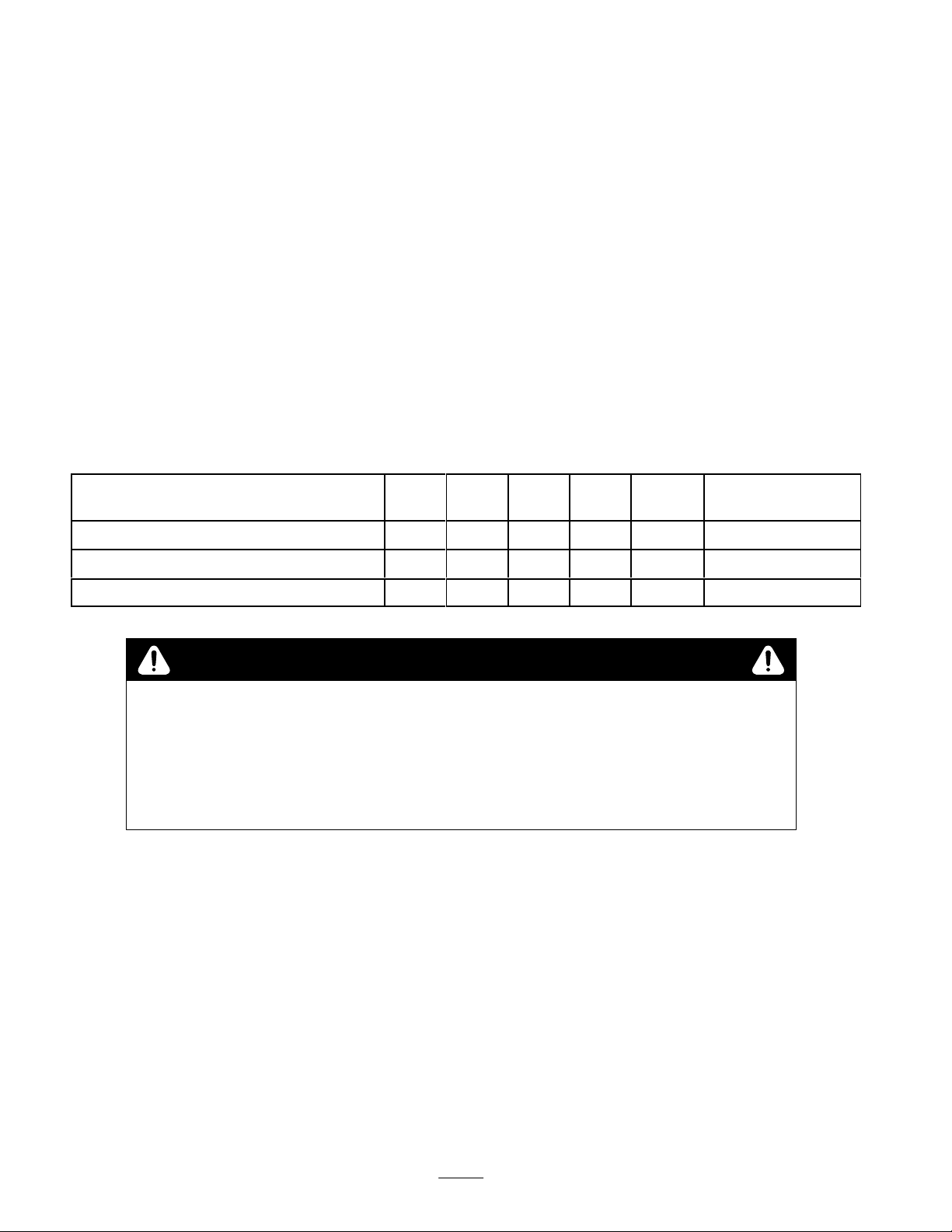
Service
Service
Blade cutting edge—check
Hydraulic hoses—inspect
Interval Chart
Operation
1. If
your traction unit has a speed selector
fast (rabbit) position.
2.
Pull the auxiliary hydraulics valve to the operator grip
to angle the blade to the right.
3.
Push the auxiliary hydraulics valve away from the
operator grip to angle the blade to the left.
Each
Use5Hours25Hours
200
Hours
X X
Storage
Service
X
, move it to the
Notes
Replace if damaged
Chipped surfaces—paint
POTENTIAL
•
If you leave the key in the ignition switch, someone could start the engine.
WHA
•
Accidental starting of the engine could seriously injur
HOW T
•
Remove the key fr
Checking
T CAN HAPPEN
the Blade Cutting
HAZARD
O AVOID THE HAZARD
om the ignition switch befor
Edge
Check
the blade cutting edge once a year for wear
blade is badly worn, complete the following procedure:
1.
Remove the pins securing the blade to the frame and
hydraulic cylinder and remove the blade.
2. T
urn the blade 180 degrees so the worn edge is on top,
then install it back on the mounting frame and
hydraulic cylinder
.
. If the
CAUTION
e you do any maintenance.
Storage
1.
2.
3.
4.
X
e you or other bystanders.
Before long term storage, wash the attachment with
mild deter
Check the condition of the cutting edge. Remove and
rotate the blade 180 degrees so the worn edge is on
top, if it is badly worn.
Check and tighten all bolts, nuts, and screws. Repair or
replace any part that is damaged or worn.
Ensure that all hydraulic couplers are connected
together to prevent contamination of the hydraulic
system.
gent and water to remove dirt and grime.
Paint all scratched or bare metal surfaces. Paint is
5.
available from your Authorized Service Dealer
4
.
Page 5

6.
Store the attachment in a clean, dry garage or storage
area. Cover it to protect it and keep it clean.
Troubleshooting
PROBLEM POSSIBLE
Blade will not change angle.
CAUSES
1.
Hydraulic coupler not
completely connected
2.
Defective hydraulic coupler
3.
An obstruction in a hydraulic
hose
4.
Auxiliary valve on the traction
unit is not opening.
5.
Defective hydraulic cylinder
CORRECTIVE ACTION
1.
Check and tighten all couplers.
2.
Check couplers and replace
any that are defective.
3.
Find and remove the
obstruction.
4.
Repair the valve.
5.
Replace or repair defective
cylinder.
5
Page 6

Page 7

Page 8

 Loading...