

Page 1

Backhoe
Sitework Systems Attachment
Model No. 22412—990001 & Up
Form No. 3321-518
Operator’s Manual
English (CE)
Page 2

Contents
Page
Introduction 2.
Safety 2
Safety Decals3. . . . . . . . . . . . . . . . . . . . . . . . . . . . .
Specifications 4
Stability Ratings4. . . . . . . . . . . . . . . . . . . . . . . . . . .
Installation 5
Loose Parts5. . . . . . . . . . . . . . . . . . . . . . . . . . . . . . .
Initial Assembly5. . . . . . . . . . . . . . . . . . . . . . . . . . .
Greasing the Backhoe6. . . . . . . . . . . . . . . . . . . . . .
Installing the Backhoe on the T
Installing a Bucket7. . . . . . . . . . . . . . . . . . . . . . . . .
Adjusting the Seat8. . . . . . . . . . . . . . . . . . . . . . . . .
Removing the Backhoe from the T
Operation 9
Operation Checklist9. . . . . . . . . . . . . . . . . . . . . . . .
Backhoe Overview10. . . . . . . . . . . . . . . . . . . . . . . . .
Controls 10
Operating the Backhoe10. . . . . . . . . . . . . . . . . . . . . .
Maintenance 12
Service Interval Chart13. . . . . . . . . . . . . . . . . . . . . .
Greasing and Lubrication13. . . . . . . . . . . . . . . . . . . .
Changing the Bucket Orientation13. . . . . . . . . . . . . .
Changing the Boom Speed14. . . . . . . . . . . . . . . . . . .
Storage 14
Troubleshooting 15
. . . . . . . . . . . . . . . . . . . . . . . . . . . . . . . .
. . . . . . . . . . . . . . . . . . . . . . . . . . . . . . . . . . . . . .
. . . . . . . . . . . . . . . . . . . . . . . . . . . . . . . .
. . . . . . . . . . . . . . . . . . . . . . . . . . . . . . . . . .
raction Unit6. . . . .
raction Unit8. . .
. . . . . . . . . . . . . . . . . . . . . . . . . . . . . . . . . . .
. . . . . . . . . . . . . . . . . . . . . . . . . . . . . . . . .
. . . . . . . . . . . . . . . . . . . . . . . . . . . . . . . . .
. . . . . . . . . . . . . . . . . . . . . . . . . . . . . . . . . .
. . . . . . . . . . . . . . . . . . . . . . . . . . . . . .
Introduction
For your convenience, write the product model and serial
numbers in the space below
Model No:
Serial No.
The
warning system in this manual identifies potential
hazards and has special safety messages that help you and
others avoid personal injury
W
ARNING and CAUTION are signal words used to
identify the level of hazard. However
hazard, be extremely careful.
DANGER
serious injury or death if the recommended precautions
are not followed.
WARNING
or death if the recommended precautions are not followed.
CAUTION
moderate injury if the recommended precautions are not
followed.
wo other words are also used to highlight information.
T
“Important” calls attention to special mechanical
information and “Note” emphasizes general information
worthy of special attention.
The left and right side of the machine is determined by
standing in the normal operator’s position.
signals an extreme hazard that will cause
signals a hazard that may cause serious injury
signals a hazard that may cause minor or
.
, even death. DANGER,
, regardless of the
W
e want you to be completely satisfied with your new
product, so feel free to contact your local Authorized
Service Dealer for help with service, genuine replacement
parts, or other information you may require.
Whenever you contact your Authorized Service Dealer or
the factory
your product. These numbers will help the Service Dealer
or Service Representative provide exact information about
your specific product. Y
number on a plate located on the product.
, always know the model and serial numbers of
ou will find the model and serial
The Toro Company – 1999
8111 Lyndale Ave. South
Bloomington, MN 55420–1196
Safety
Impr
oper use or maintenance by the operator or owner
can r
esult in injury
comply with the safety instructions in the traction unit
operator’
safety alert
W
ARNING, or DANGER—“personal safety
instruction.” Failur
may r
2
s manual and always pay attention to the
esult in personal injury or death.
. T
o r
educe the potential for injury
symbol, which means CAUTION,
e to comply with the instruction
All Rights Reserved
Printed in the USA
,
Page 3
DANGER
WARNING
POTENTIAL HAZARD
• Ther
WHA
•
HOW T
•
e may be buried power
telephone lines in the work ar
, gas, and/or
ea.
T CAN HAPPEN
Electric shock, death, or explosion may occur
O AVOID THE HAZARD
Have the pr
operty or work ar
ea marked for
buried lines and do not dig in marked ar
DANGER
POTENTIAL HAZARD
• Ther
WHA
•
HOW T
•
e may be overhead power lines in the work
area.
T CAN HAPPEN
Electric shock or death may occur if a power
line is touched by the backhoe.
O AVOID THE HAZARD
Survey and mark the ar
ea wher
e ther
e ar
overhead power lines, and dig with caution
under power lines, to ensur
e that you do not
touch them with the backhoe.
eas.
e
POTENTIAL HAZARD
•
When going up or down hill, the machine could
overturn if the heavy end is toward the
downhill side.
.
WHA
T CAN HAPPEN
•
Someone may be pinned or seriously injured by
the machine if it overturns.
HOW T
•
O AVOID THE HAZARD
Operate up and down slopes with the backhoe
uphill.
CAUTION
POTENTIAL HAZARD
•
The tir
es of the traction unit can be slippery
WHA
T CAN HAPPEN
•
If the tir
es ar
e used as a step to climb on to or
off of the backhoe, the operator could slip and
fall, causing injury
HOW T
•
O AVOID THE HAZARD
Use the step pr
.
ovided when climbing on to or
off of the backhoe and not the traction unit
tires.
.
Safety
1
9
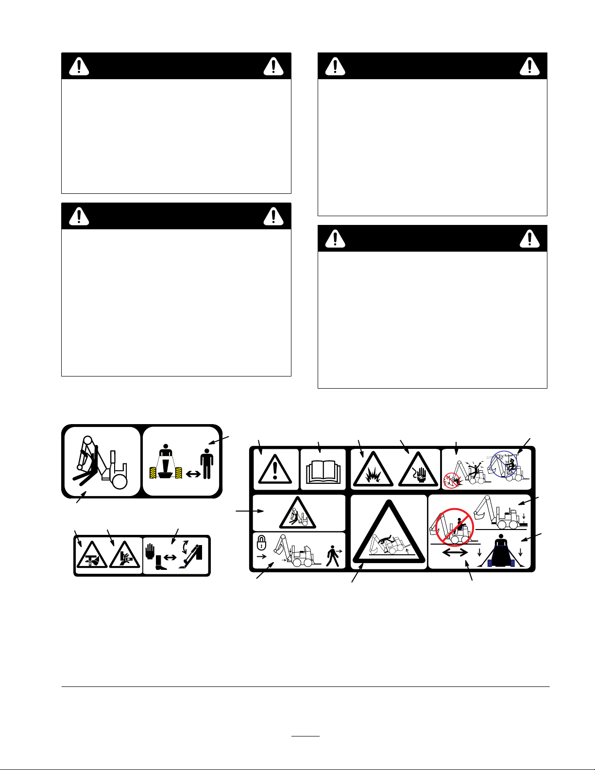
1. Crushing
body
2.
Keep bystanders away
3.
Safety alert symbol
4.
Read the operator’s manual
5.
Explosive hazard
Decals
# 100–4132
10
hazard—whole
2
1
11
6.
Electric shock hazard
7.
Do not dig in areas with
underground utilities
8.
Do not allow the backhoe to
contact
overhead power lines
9. Crushing
hazard—foot
12
3
4
5 6
7
8
16
15
Figure
13
# 100–4133# 100–4136
1
10.
Crushing hazard—hand
11.
Keep hands and feet away
from moving stabilizers
12.
Secure the boom before
leaving the machine
13. T
ipping hazard
14.
15.
16.
14
Do not move the traction unit
while seated on the backhoe
Lower the stabilizers before
beginning work
Use the counterweight
3
Page 4
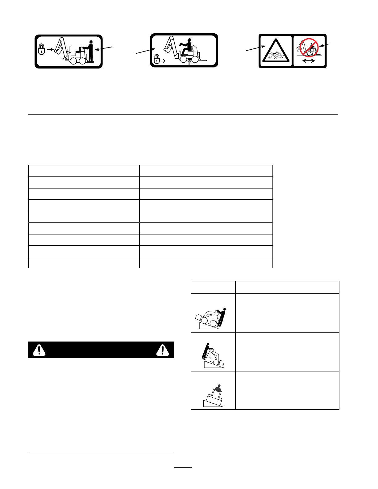
1
2
3
# 100–4137# 100–4134 # 100–4135
4
Figure
1. Secure
the boom before
transporting the backhoe
2.
Install and secure the side
bars before operating the
backhoe
3. T
Specifications
Note:
Specifications and design are subject to change without notice.
Width 34.5
Length 1
T
ransport height
Fully raised height
Weight
Digging depth (maximum) 79 inches (200.6 cm)
Bucket rotation
Swing arc
Stabilizer spread (working)
inches (87.6 cm)
12.5 inches (286 cm)
84 inches (213 cm)
1
15 inches (292 cm)
710 lbs (322 Kg)
135 degrees
151 degrees
130 inches (330 cm)
2
ipping hazard
4.
Do not move the traction unit
while seated on the backhoe
Stability
To
determine the degree of slope you can traverse with the
backhoe installed on a traction unit, find the stability
rating for the hill position you want to travel in the
following table, then find the degree of slope for the same
rating and hill position in the Stability Data section of the
traction unit operator’s manual.
Ratings
WARNING
POTENTIAL HAZARD
•
Exceeding the maximum r
can cause the traction unit to tip.
WHA
T CAN HAPPEN
•
If the traction unit tips, you or bystanders could
be crushed.
HOW T
•
O AVOID THE HAZARD
Do not drive the traction unit on a slope steeper
than the maximum r
determined in the following table and the
traction unit operator’s manual.
ecommended slope
ecommended slope, as
Orientation
Front Uphill
Stability Rating
C
Rear Uphill
D
Side Uphill
C
IMPORTANT:
operator’
on the platform while using the backhoe, or the
traction unit will become unstable.
If your traction unit has a r
s platform, the counterweight must be used
ear
4
Page 5
Installation
Loose
Note:
DESCRIPTION
Side
Back-plate
Bolt
Nut
Side bar
Long tilt cylinder pin
Cotter pin
Linch pin
Link
Bucket, 9, 12, or 16 inch (23, 30, or 41 cm)
Initial
Parts
Use the chart below to identify parts for assembly
bar bracket
Assembly
Installing the Side Bar Bracket
.
QTY. USE
2
2
6
6
2
1
2
2
2
1
Install the side bar brackets and attach to the
backhoe.
Replace the tilt cylinder pin and connect to the
backhoe.
Install on the backhoe. Must be purchased
separately.
1
1. Remove
under the control panel (models 22305 and 22305TE
only).
Remove the battery from the traction unit. Refer to
2.
your traction unit operator’s manual.
Note:
you do not need to remove the battery; however
need to remove the loader arm cylinder and exhaust cover
plate on the right side of the machine. To remove the
loader arm cylinder
install the cylinder lock on the left side before removing
the right cylinder
finished installing the side bar bracket.
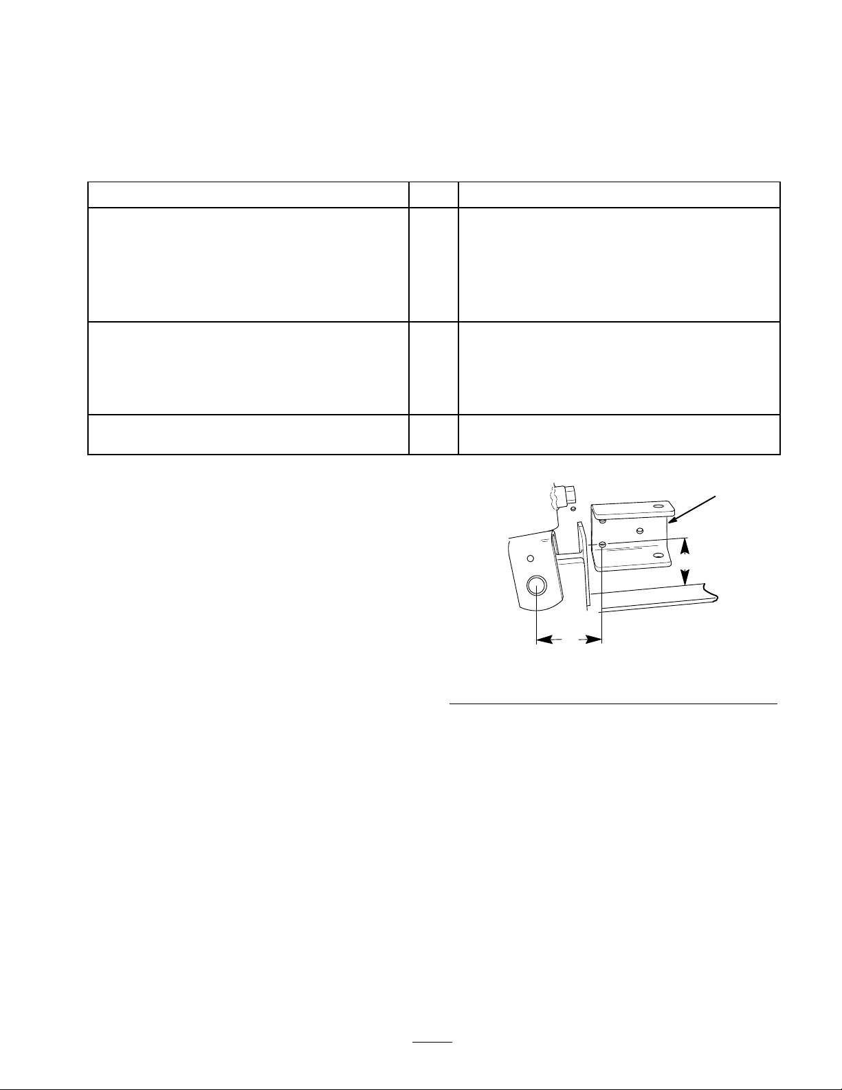
3.
Line up the side bar bracket as illustrated in Figure 3
and mark the centers of the three holes.
the traction unit manual holder and relocate it
If you have a four
-wheel drive, diesel traction unit,
, you need to raise the loader arms and
. Replace the cylinder and plate when
, you do
3.5 in. (8.9 cm)
m–4560
1. Side
4. Drill
5.
bar bracket
three, 0.568 in. (1.43 cm) diameter holes through
the side of the traction unit at the marked locations.
Secure the side bar bracket to the side of the traction
unit using the back-plate, three carriage bolts, and
three nuts.
3.2 in. (8.1 cm)
Figure
3
2.
3.2 in. (8.1 cm)
5
Page 6

3
2
Greasing
Before
using the backhoe for the first time, grease all of
the fittings; refer to Greasing and Lubrication, page 13.
the Backhoe
4
1
Figure
1. Side
bar bracket
2. Back-plate
6. Torque
7.
the nuts to 75 ft-lbs (102 N·m).
Repeat steps 3–6 for the other side of the traction unit.
4
Carriage bolt
3.
4. Nut
Changing the Tilt Cylinder Pin
1. Remove
(Fig. 5).
2.
Using a hammer and punch, remove the tilt cylinder
pin.
the bolt securing the upper tilt cylinder pin
2
3
m–4586
Installing
T
raction Unit
IMPORTANT:
the traction unit, ensur
the Backhoe on the
Befor
e connecting any attachments to
e that the mount plates ar
e fr
of any dirt or debris.
1.
Start the engine.
2. T
ilt the attachment mount plate forward.
3.
Drive forward, positioning the mount plate into the
upper lip of the receiver plate (Fig. 7).
IMPORTANT
r
eceiver plate so that the gaps on the sides are equal. If
: Y
ou must center the mount plate in the
you do not center the plates, you may not be able to
install the side bars.
1
2
ee
1
m–4562
Figure
1. Tilt
cylinder
2. T
ilt cylinder pin
3. Apply
4.
a generous coating of grease to the new pin.
Install the new pin into position and secure it with two
5
3. Bolt
cotter pins (Fig. 6).
Note:
Leave the new pin installed, even when the backhoe
is removed.
1
2
m–4563
1. New
Figure
tilt cylinder pin
6
2.
Cotter pin
Figure
1. Mount
4. Tilt
plate
the mount plate back until the receiver plate
7
2.
contacts the mount plate
5.
Engage the attachment lock pins (Fig. 8).
1
Figure
1. Attachment
6. Tilt
lock pins (shown in engaged position)
the backhoe part of the way back.
8
m–4055
Receiver plate
m–4056
6
Page 7

7.
Stop the engine.
8.
Move the auxiliary hydraulic lever forward, backward,
and back to the neutral position to relieve hydraulic
pressure at the hydraulic couplers.
IMPORTANT
cleaned fr
: Ensur
e that all for
eign matter is
om hydraulic connections befor
e making
connections.
Remove protective covers from hydraulic couplers on
9.
the traction unit. Connect covers together to prevent
contamination during operation.
10.
Slide the collars back on the hydraulic couplers and
connect the attachment couplers to the machine
couplers.
Note: You may need to move the attachment tilt lever to
line up the holes in the links with the pins.
4
4
1
2
1. Tilt
cylinder pin
2.
Backhoe link pin
3
Figure
9
3. Link
4.
Linch pin
m–4130
WARNING
POTENTIAL HAZARD
•
Hydraulic fluid escaping under pr
penetrate skin and cause injury
WHA
T CAN HAPPEN
•
Fluid accidentally injected into the skin must be
surgically r
emoved within a few hours by a
.
essur
e can
doctor familiar with this form of injury or
gangr
ene may r
HOW T
•
O AVOID THE HAZARD
Keep body and hands away from pin hole leaks
or nozzles that eject high pr
esult.
essur
e hydraulic
fluid.
Use cardboard or paper to find hydraulic leaks,
•
never use your hands.
11.
Confirm that the connection is secure by pulling on the
hoses.
Start the engine.
12.
13.T
ilt the backhoe all the way back.
CAUTION
15.Install
the side bars on each side as illustrated in
Figure 10.
16.
If the bars do not fit snuggly
, remove them, loosen the
jam nut, and thread the compound side bar together or
apart as needed to ensure that they fit as tight as
possible (Fig. 10). T
Note:
If you have a four
ighten the jam nut when finished.
-wheel drive, diesel traction unit,
you may need to loosen the hood and slide it up in the
mounting slots to ensure that the hood does not interfere
with the side bars.
2
4
3
1. Side
2. Pin
bar
Figure
10
Hairpin cotter
3.
4.
Jam nut
1
m–4561
POTENTIAL HAZARD
• T
ilting the backhoe can can pinch hands.
WHA
T CAN HAPPEN
• Y
ou could pinch and/or crush your hand when
adjusting the seat.
HOW T
•
O AVOID THE HAZARD
Keep away fr
om the moving backhoe when
tilting.
14.
Slide the two links on each end of the tilt cylinder pin
and the backhoe link pin and secure them with two
linch pins (Fig. 9).
Installing
The
backhoe does not come with a bucket installed
a Bucket
because several sizes of buckets are available for you to
choose from. Install your bucket as follows:
1.
Install the backhoe onto the traction unit and raise the
dipperstick above the ground.
2.
Remove the bolts and nuts securing each of the two
bucket pins to the dipperstick (Fig. 1
Remove the pins.
3.
1).
7
Page 8

4.
Align the pin holes in the bucket with the mounting
holes in the dipperstick (Fig. 1
Secure the bucket with the pins, bolts, and nuts
5.
removed previously (Fig. 1
1
4
1).
1).
4
2
1
3
Figure 11
1. Dipperstick
2. Bucket
pin
Adjusting
the Seat
3. Bolt
4. Nut
CAUTION
POTENTIAL
•
The seat mounting bracket has several pinch
points.
WHA
T CAN HAPPEN
• Y
ou could pinch and/or cut your fingers when
adjusting the seat.
HOW T
• T
ake car
seat mounting bracket when moving the seat up
and down and when lowering the seat into
position.
HAZARD
O AVOID THE HAZARD
e to keep your fingers away fr
2
m–4589
om the
3
Figure
1. Seat
2. Knobs
5. When
Removing
the T
1. With
2.
3.
you have the proper height, install the pin and
hairpin cotter to secure the seat.
the Backhoe from
raction Unit
the backhoe secured in the transport position
(refer to Preparing for T
backhoe to a level storage area and stop the engine.
Remove the hairpin cotters and pins securing the side
bars and remove the side bars.
Pin the side bars in the storage positions as illustrated
in Figure 13.
12
3. Pin
and hairpin cotter
ransport, page 12), move the
m–4547
1.
Stop the engine.
2. T
ilt the seat forward.
3.
Loosen the knobs on the bottom of the seat (Fig. 12)
and slide the seat forward or back as needed.
4. T
o adjust the seat height, remove the hairpin cotter and
pin from the seat stand (Fig. 12) and raise or lower the
seat as required.
Figure
4. Start
5.
Note: You may need to adjust the tilt lever slightly to
loosen the links.
the engine.
Remove the linch pins securing the links and remove
the links.
13
8
m–4590
Page 9

6.
Secure the links and two linch pins for storage on the
pins on the backhoe and the other two linch pins on the
traction unit tilt cylinder pin.
7. T
ilt the backhoe forward slowly until the storage
supports on the backhoe receiver plate and the bucket
contact the ground.
CAUTION
POTENTIAL HAZARD
•
If the backhoe is r
unit without a bucket installed on the
dipperstick, the backhoe will be unstable.
WHA
T CAN HAPPEN
•
The backhoe could tip over injuring you or
other bystanders and damaging the backhoe.
HOW T
•
8.
9.
O AVOID THE HAZARD
Do not remove the backhoe fr
unit without first installing a bucket onto the
backhoe.
Stop the engine.
Move the auxiliary hydraulic lever forward, backward,
and back to the neutral position to relieve hydraulic
pressure at the hydraulic couplers.
emoved fr
om the traction
om the traction
Operation
Note:
Always use the traction unit to lift and move the
attachment.
Operation
To
ensure safe, ef
you complete the following activities before, during, and
after operating the backhoe:
Note:
For detailed descriptions of these procedures, refer
to Installing the Backhoe on the T
and Operating the Backhoe (page 10).
Befor
e Operation:
•
Locate and mark under
•
Install the counterweight on the traction unit.
•
Install the links between the backhoe and the tilt
cylinder pin on the traction unit.
•
Install the side bars between the backhoe and the
traction unit frame.
•
Install the hydraulics lever clamp over the traction unit
controls.
Lower the stabilizer arms before digging.
•
Checklist
fective use of the backhoe, ensure that
raction Unit (page 6)
ground utilities.
10.
Slide the collar back on hydraulic couplers and
disconnect them.
11.
Install protective covers onto the hydraulic couplers on
the traction unit.
12.
Connect the attachment hoses together to prevent
hydraulic system contamination during storage.
13.
Disengage the attachment lock pins by turning them to
the outside.
14.
Start the engine.
15.T
ilt the mount plate forward and back the traction unit
away from the backhoe.
During Operation:
Only operate the backhoe from the backhoe seat.
Only move the traction unit from the traction unit
operator’
After Operation:
Install the pins securing the boom from moving up and
down and side to side (Figs. 17 and 18) before leaving the
backhoe unattended.
s position and not from the seat of the backhoe.
9
Page 10

Backhoe
Figure
14 illustrates the backhoe. Familiarize yourself
Overview
with all of the components listed in Figure 14.
Y
ou can also move the boom control lever into an
intermediate position (i.e., forward and left, forward and
right, rearward and left, or rearward and right) to swing
the boom at the same time as you raise or lower it.
2
3
1
7
6
Figure
1. Seat
2. Controls
3. Boom
4. Dipperstick
14
5. Bucket
6. Stabilizer
7. Speed
Controls
Familiarize
Figure 15 before you operate the backhoe.
yourself with all of the controls listed in
4
5
m–4587
adjustment valve
Dipperstick/Bucket Control Lever
Move
the dipperstick/bucket control lever forward to
extend the dipperstick and rearward to retract the
dipperstick. Move the dipperstick/bucket control lever to
the right to dump the bucket and move it left to load the
bucket.
ou can also move the dipperstick/bucket control lever
Y
into an intermediate position (i.e., forward and left,
forward and right, rearward and left, or rearward and
right) to extend or retract the dipperstick at the same time
as you load or dump the bucket.
Operating
the Backhoe
Preparing the Backhoe
1. Drive
2.
3.
to the work location.
If your traction unit has a parking brake, engage it.
Pull the auxiliary hydraulics lever to the operator grip
and install the hydraulics lever clamp by pushing it
over the hand grip and sliding it right so that the pin
through the clamp slides under the right hand grip
(Fig. 16).
1
1. Stabilizer
2.
Boom control lever
2
control levers
Figure
15
3.
Dipperstick/bucket control
lever
3
m–4546
Stabilizer Control Levers
Move
the stabilizer control levers forward to lower the
stabilizers and rearward to raise the stabilizers.
Boom Control Lever
Move
the boom control lever forward to lower the boom
and rearward to raise the boom. Move the boom control
lever to the right to swing the boom to the right and move
it left to swing the boom to the left.
1
2
1. Hydraulics
2. Pin
4. Push
the stabilizer control levers forward to lower both
Figure
lever clamp
16
Auxiliary hydraulics lever
3.
stabilizers until they touch the ground and the front
wheels of the traction unit come of
f of the ground
slightly.
Remove the two pins locking the boom in place (Figs.
5.
17 and 18) and place them in the storage positions
(Fig. 19).
Note:
One pin prevents the boom from swinging side to
side (Fig. 17) and the other prevents the boom from
moving up and down (Fig. 18).
3
m–4641
10
Page 11

1
A
2
m–4548
Figure
1. Pin 2. Linch
17
1
Figure
1. Pin 2. Linch
18
pin
pin
1
2
m–4550
B
C
m–4554/4555/4556
Figure
To
empty the bucket you swing it to the left or right and
20
extend the dipperstick and uncurl bucket, dumping the
load (Fig. 21).
A
B
m–4557/4558
2
m–4549
Figure
1. Pin 2. Linch
19
pin
Digging a Hole
Using
a backhoe with precision and proficiency takes time
and practice. In general you dig a hole by extending the
dipperstick and bucket, lowering them into the ground,
and then pullback on the dipperstick while raising the
boom and curling the bucket rearwards (Fig. 20).
Figure
The
distance you extend the dipperstick and bucket and
21
the size of bite you take will vary greatly with the soil
type, moisture content of the soil, and obstructions in the
soil, such as tree roots and rocks.
Spend some time practicing with the backhoe to get the
feel for how it operates and how to best use it in the
conditions in which you work. Please read and use the
following tips when operating the backhoe:
11
Page 12

•
Do not dig too close to the backhoe body or stabilizers.
The backhoe could undercut the stabilizers or traction
unit causing the machine to fall into the hole.
WARNING
POTENTIAL HAZARD
•
If you dig too close to the backhoe, the backhoe
could fall into the hole.
WHA
T CAN HAPPEN
•
The backhoe and traction unit could tip on top
of you into the hole causing sever
HOW T
• Ensur
•
•
•
•
O AVOID THE HAZARD
e that you do not dig within thr
the backhoe or stabilizers.
Do not take lar
bucket through the soil using the swinging motion of
the dipperstick a few inches deep at a time.
If the bucket catches in the soil, uncurl the bucket,
raise the boom slightly
If your traction unit has a speed selector
fast position (rabbit) while you are learning how to
operate the backhoe (this will slow the backhoe down).
Set it to the slow position (turtle) once you feel you
have mastered the use of the backhoe.
If your traction unit has a flow divider
o’clock position.
ge bites of soil. Instead, sweep the
, and continue digging.
Preparing for Transport
1. Fully
2.
3.
raise the boom, retract the dipperstick, and curl
the bucket rearward (Fig. 14). Ensure that you center
the boom locking pin holes as much as possible.
Pull the stabilizer levers rearward until the stabilizers
are fully raised.
Stop the engine and remove the key
e injury
.
.
ee feet of
, set it to the
, set it to the 1
CAUTION
POTENTIAL HAZARD
•
If you do not secur
lower during transport.
WHA
T CAN HAPPEN
•
The traction unit could become unstable
causing loss of contr
could be injur
HOW T
•
5.
6.
1
1. Pin
2. Clamp
7. Slowly
O AVOID THE HAZARD
Always secur
the traction unit of on a trailer
Remove the hydraulics lever clamp (Fig. 16).
Secure the clamp under the backhoe seat by inserting
the end of the pin in the clamp into the hole in the seat
support (Fig. 22).
transport the backhoe as needed.
e the boom, it could swing or
ol and you or bystanders
ed.
e the boom befor
Figure
e transport with
.
3
22
3. Hole
in seat support
2
1
m–4644
Maintenance
Secure the boom using the two pins removed prior to
4.
operation (Figs. 17 and 18).
POTENTIAL HAZARD
•
If you leave the key in the ignition switch,
someone could start the engine.
WHA
T CAN HAPPEN
•
Accidental starting of the engine could seriously
injur
e you or other bystanders.
HOW T
•
O AVOID THE HAZARD
Remove the key fr
you do any maintenance.
12
CAUTION
om the ignition switch befor
e
Page 13

Service
Service
Operation
Interval Chart
Hours
8
Storage
Service
Grease fittings
Chipped surfaces–paint
Greasing
and Lubrication
X X
X
Service Interval/Specification
Grease
all fittings every 8 operating hours (Fig. 23). Note
that in most cases the grease fittings are located in the
center of every pivot pin. Grease all fittings immediately
after every washing.
Grease Type: General-purpose grease
How to Grease
1. Stop
2.
3.
4.
the engine and remove the key
Clean the grease fittings with a rag.
Connect a grease gun to each fitting.
Pump grease into the fittings until grease begins to
ooze out of the bearings.
.
m–4587
m–4552
5. W
ipe up any excess grease.
Changing
Figure
the Bucket
23
Orientation
You
can change the angle that the bucket is mounted on
the dipperstick to a position that allows you to dig more
vertically
foundation, or dig a square sided hole. T
orientation, complete the following procedure:
1.
2.
3.
4.
. This will allow you to dig very close to a
o change the
Remove the bolts and nuts securing the upper bucket
pin (Fig. 24).
Remove the pin.
Swing the bucket up, aligning the second set of holes
with the mounting holes on the dipperstick (Fig. 24).
Secure the bucket with the pin, bolt, and nut removed
previously.
13
Page 14

1
m–4589
4
4
The
two valves that control the left and right swing of the
boom are located inside of the controls access panel
(Fig. 26). T
the panel. Adjust both valves equally
o access these valves, remove six locknuts and
. Replace the access
panel when finished.
5
1
2
3
Figure
1. Dipperstick
2. Upper
3. Bolt
Changing
You
bucket pin
the Boom Speed
can change the speed that the boom moves up and
24
4. Nut
5.
Second set of holes
down and left and right by changing the setting of three
speed adjustment valves. The valve that controls the up
and down movement is located on top of the boom (Fig.
14).
3
1
4
5
2
1. Speed
2. Knob
3.
Set screw
Figure
adjustment valve
25
4. Slow
5. Fast
m–4551
Figure
1. Controls
To
adjust the valves, complete the following procedure
access panel
26
and refer to Figure 25.
1.
Loosen the set screw located on the side of the knob
on the valve.
2. T
o increase the speed of the boom, turn the knob
counter-clockwise.
o decrease the speed of the boom, turn the knob
3. T
clockwise.
ighten the set screw
4. T
.
Storage
1.
Before long term storage wash the attachment with
mild deter
2.
Apply grease to all grease fittings.
3.
Check and tighten all bolts, nuts, and screws. Repair or
replace any part that are damaged or worn.
4.
Paint all scratched or bare metal surfaces. Paint is
available from your Authorized Service Dealer
gent and water to remove dirt and grime.
m–4587
.
14
Store the attachment in a clean, dry garage or storage
5.
area. Cover it to protect it and keep it clean.
Page 15

Troubleshooting
p(
yg
PROBLEM POSSIBLE
Backhoe does not operate
CAUSES
1.
Hydraulic coupler not
completely connected
2.
Auxiliary hydraulics valve on
the traction unit is not fully
engaged.
3. T
ransport pins were not
removed.
4.
Hydraulic fluid level is low
5.
Damaged hydraulic coupler
6.
Obstructed hydraulic hose
7.
Pinched hydraulic hose
8.
Auxiliary hydraulic valve on the
traction unit is not opening.
9.
Hydraulic coupler not
completely connected
10.
Bent piston rod
1.
2.
3.
. 4.
5.
6.
7.
8.
9.
10.
CORRECTIVE ACTION
Check and tighten all couplers.
Engage the valve.
Remove the pins.
Fill the traction unit hydraulic
tank.
Check couplers and replace
any that are defective.
Find and remove the
obstruction.
Replace the hose.
Repair the valve.
Check and tighten all couplers.
Contact your Authorized T
Dealer.
oro
Backhoe is operating slowly
Backhoe fails to hold up a load (all
loads will normally settle down
over a long period of time)
Hydraulic oil leakage
1.
Hydraulic oil is cold.
2.
Engine speed is too slow
3.
Speed adjustment valve is set
too slow
4.
Pinched hydraulic hose
5.
Speed adjustment valve is
leaking oil.
6.
Damaged cylinder
7.
Damaged hydraulic pump
1.
Damaged hydraulic hose
2.
Damaged cylinder
3.
Damaged control valve
1.
Damaged hydraulic hose
.
1.
. 2.
3.
4.
5.
6.
7.
1.
2.
3.
1.
Allow the engine to warm the
oil before operating.
Increase the throttle speed of
the traction unit.
Adjust the speed adjustment
valve to obtain the desired
speed.
Replace the hose.
Contact your Authorized T
Dealer.
Contact your Authorized T
Dealer.
Contact your Authorized T
Dealer.
Replace the hose.
Contact your Authorized T
Dealer.
Contact your Authorized T
Dealer.
Replace the hose.
oro
oro
oro
oro
oro
2.
Damaged hydraulic system
15
2.
Contact your Authorized T
Dealer.
oro
Page 16

PROBLEM
gg
jy
POSSIBLE CAUSES
CORRECTIVE ACTION
Swing cylinder malfunctioning
Control valve sticking or working
hard
Backhoe operation is spongy or
jerky
1.
Damaged cylinders, swing
restrictors, or cross-over relief
valve
1.
Dirty hydraulic oil
2.
Damaged or dirty valve
3.
Damaged cylinder
1.
Hydraulic fluid level is low
2.
Air in the hydraulic system
3.
Hydraulic oil is cold.
4.
Pinched hydraulic hose
1.
1.
2.
3.
. 1.
2.
3.
4.
Contact your Authorized T
Dealer.
Change the hydraulic oil.
Contact your Authorized T
Dealer.
Contact your Authorized T
Dealer.
Fill the traction unit hydraulic
tank.
Extend the cylinders as far as
possible and hold them in an
extended position for several
seconds.
Allow the engine to warm the
oil before operating.
Replace the hose.
oro
oro
oro
16
 Loading...