

Page 1
4
in 1 Bucket
Sitework Systems Attachment
Model No. 22411—890001 & Up
Form No. 3323-253
Operator’s Manual
English (CE)
Page 2
Contents
WARNING
or death if the recommended precautions are not followed.
signals a hazard that may cause serious injury
Page
Introduction 2.
Safety 2
Safety Decal3. . . . . . . . . . . . . . . . . . . . . . . . . . . . . .
Specifications 4
Maximum Material Density at Capacity4. . . . . . . .
Stability Ratings5. . . . . . . . . . . . . . . . . . . . . . . . . . .
Operation 6
Modes of Operation6. . . . . . . . . . . . . . . . . . . . . . . .
Bucket Operation and Controls7. . . . . . . . . . . . . . .
Maintenance 7
Service Interval Chart7. . . . . . . . . . . . . . . . . . . . . .
Storage 7
Troubleshooting 7
. . . . . . . . . . . . . . . . . . . . . . . . . . . . . . . .
. . . . . . . . . . . . . . . . . . . . . . . . . . . . . . . . . . . . . .
. . . . . . . . . . . . . . . . . . . . . . . . . . . . . . . .
. . . . . . . . . . . . . . . . . . . . . . . . . . . . . . . . . . .
. . . . . . . . . . . . . . . . . . . . . . . . . . . . . . . . .
. . . . . . . . . . . . . . . . . . . . . . . . . . . . . . . . . .
. . . . . . . . . . . . . . . . . . . . . . . . . . . . . .
Introduction
W
e want you to be completely satisfied with your new
product, so feel free to contact your local Authorized
Service Dealer for help with service, genuine replacement
parts, or other information you may require.
Whenever you contact your Authorized Service Dealer or
the factory
your product. These numbers will help the Service Dealer
or Service Representative provide exact information about
your specific product. Y
number on a plate located on the back of the bucket.
For your convenience, write the product model and serial
numbers in the space below
, always know the model and serial numbers of
ou will find the model and serial
.
CAUTION
moderate injury if the recommended precautions are not
followed.
wo other words are also used to highlight information.
T
“Important” calls attention to special mechanical
information and “Note” emphasizes general information
worthy of special attention.
The left and right side of the machine is determined by
standing in the normal operator’s position.
signals a hazard that may cause minor or
Safety
Impr
oper use or maintenance by the operator or owner
can r
esult in injury
comply with these safety instructions and those in the
traction unit operator’s manual. Always pay attention
to the safety alert
W
ARNING, or DANGER—“personal safety
instruction.” Failur
may r
esult in personal injury or death.
POTENTIAL HAZARD
• Ther
WHA
•
HOW T
•
e may be buried power
telephone lines in the work ar
T CAN HAPPEN
Shock or explosion may occur
O AVOID THE HAZARD
Have the pr
buried lines and don’t dig in marked ar
. T
o r
educe the potential for injury
symbol, which means CAUTION,
e to comply with the instruction
DANGER
, gas, and/or
ea.
.
operty or work ar
ea marked for
eas.
,
Model No:
Serial No.
The
warning system in this manual identifies potential
hazards and has special safety messages that help you and
others avoid personal injury
W
ARNING and CAUTION are signal words used to
identify the level of hazard. However
hazard, be extremely careful.
DANGER
serious injury or death if the recommended precautions
are not followed.
signals an extreme hazard that will cause
, even death. DANGER,
, regardless of the
The Toro Company – 1999
8111 Lyndale Ave. South
Bloomington, MN 55420–1196
POTENTIAL HAZARD
• Ther
WHA
•
HOW T
•
2
e may be overhead power lines in the work
area.
T CAN HAPPEN
Shock may occur if a power line is touched by a
tr
ee or other object that is being transported.
O AVOID THE HAZARD
Survey and mark the ar
overhead power lines, and do not transport
tr
ees or tall objects under the power lines.
DANGER
ea wher
e ther
e ar
e
All Rights Reserved
Printed in the USA
Page 3
WARNING
CAUTION
POTENTIAL HAZARD
•
When the engine is off, attachments in the
raised position can gradually lower
WHA
T CAN HAPPEN
•
Someone nearby may be pinned or injur
.
ed by
the attachment as it lowers.
HOW T
•
O AVOID THE HAZARD
Always lower the attachment lift each time you
shut off the traction unit.
WARNING
POTENTIAL HAZARD
•
When going up or down hill, the machine could
overturn if the heavy end is toward the
downhill side.
WHA
T CAN HAPPEN
•
Someone may be pinned or seriously injured by
the machine if it overturns.
HOW T
•
O AVOID THE HAZARD
Operate up and down slopes with the heavy end
of the machine uphill. An empty bucket will
make the r
make the fr
ear end heavy and a full bucket will
ont end heavy
.
POTENTIAL HAZARD
•
If the bucket is not kept level while lifting, the
load could be inadvertently dumped on the
operator.
WHA
T CAN HAPPEN
•
The operator could be injur
ed when the load is
dumped.
HOW T
•
Safety
O AVOID THE HAZARD
When lifting the bucket, tilt it forward to keep
it level and pr
event it fr
om spilling backwards.
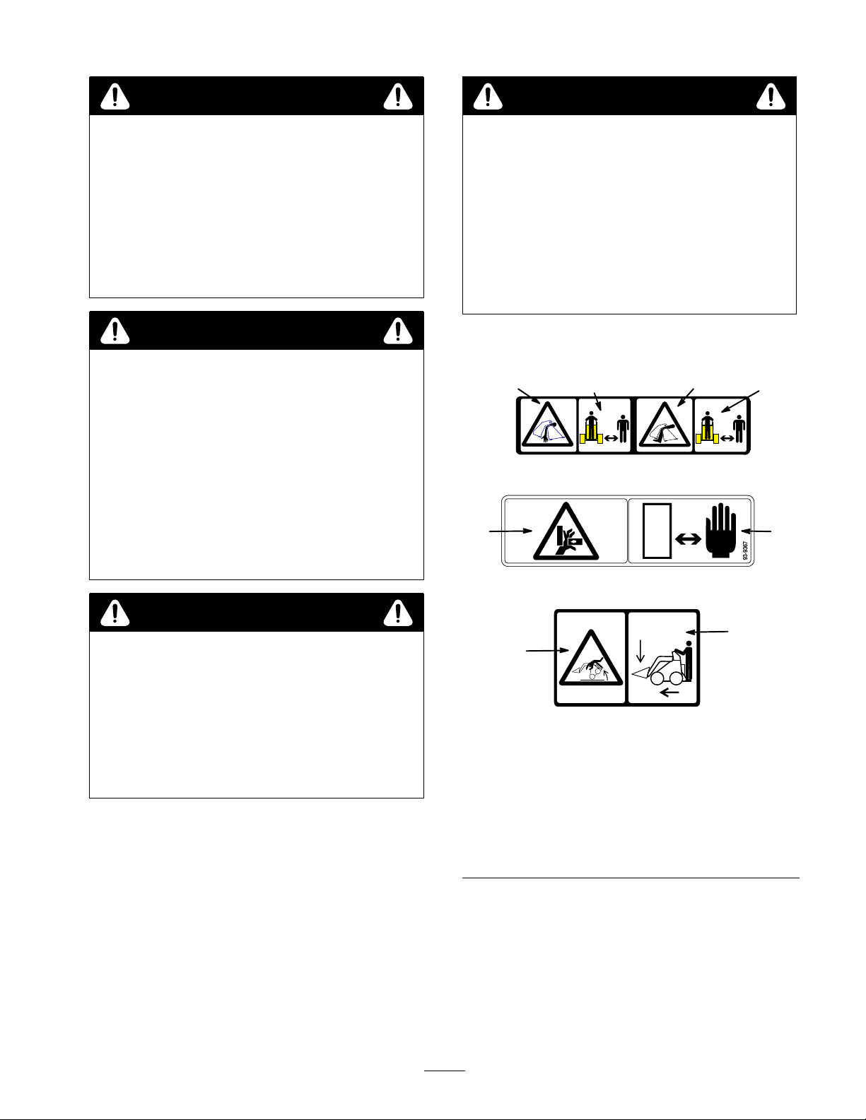
Decal
12
#
100–4648
3
4
2
5
CAUTION
POTENTIAL HAZARD
•
If you step off of the platform with the load
raised, the machine could tip forward.
WHA
T CAN HAPPEN
•
Someone nearby may be pinned or injur
HOW T
•
O AVOID THE HAZARD
Lower the bucket befor
platform.
e stepping off or the
ed.
6
1. Crushing
bucket—hand/arm
2.
Keep bystanders away
3.
Crushing hazard in
bucket—foot/leg
4. Pinching/crushing
hazard—hand
hazard in
# 93–9367
172 Kg
380 lbs
# 100–4689
Figure
1
5.
6.
7.
7
Keep hands away
Machine rollover–
exceeding rated load
capacity can cause
instability
Maximum load capacity
3
Page 4

Specifications
Note:
Specifications and design are subject to change
without notice.
Overall
Overall length
Overall height
Weight
Capacity
(SAE struck capacity)
width
41 inches (105.4 cm)
30.5 inches (77.5 cm)
20 inches (50.8 cm)
271 lbs (123 Kg)
4.3 ft3 (0.12 m3)
Maximum
Material Density at
Capacity
The
density of materials being moved by the bucket varies
and therefore so will the amount of a given material that
can be carried by the bucket before the maximum load
rating is reached. The first table lists the density of
material that can be carried, both heaped and struck (i.e.,
leveled off), in the bucket. Following that is a table
listing common materials and their densities.
T
o move materials with densities greater than the
maximum allowed for the bucket, reduce the volume of
material placed in the bucket.
Hydraulic cylinders (2):
Rod diameter
Stroke
Bore Diameter
1.25 inches (3.175 cm)
4.72 inches (12 cm)
2 inches (51.3 cm)
Material Density Chart
Material Density (Loose)
Caliche
Clay:
Natural bed
Dry
Wet
With gravel, dry 89 lb/ft3 (1420 kg/m3)
With gravel, wet
Coal:
Anthracite, broken 69 lb/ft3 (1
78lb/ft3 (1250 kg/m3)
104 lb/ft3 (1600 kg/m3)
93 lb/ft3 (1480 kg/m3)
104 lb/ft3 (1660 kg/m
96 lb/ft3 (1540 kg/m3)
100 kg/m3)
Maximum Density for Capacity Chart
Bucket
Bucket, heaped
Bucket, struck
Material Density (Loose)
Gravel:
3)
Limestone, broken or
crushed
Sand:
Capacity
Dry
Pit run (graveled sand)
Dry 1/2
(13–51mm)
W
(13–51mm)
et 1/2
I–2I
I–2I
Maximum Density
70 lb/ft3 (11
88 lb/ft3 (1403 kg/m3)
94 lb/ft3 (1510 kg/m3)
120 lb/ft3 (1930 kg/m3)
106 lb/ft3 (1690 kg/m
126 lb/ft3 (2020 kg/m
96 lb/ft3 (1540 kg/m
10 kg/m3)
3)
3)
3)
Bituminous, broken
Earth:
, packed
Dry
et, packed
W
Loam
opsoil, pulverized
T
Granite, broken or
large crushed
*Actual material density will vary from these typical values.
52 lb/ft3
94 lb/ft3 (1510 kg/m3)
100 lb/ft3 (1600 kg/m3)
78 lb/ft3 (1250 kg/m3)
59 lb/ft3 (950 kg/m
104 lb/ft3 (1660 kg/m3)
(830 kg/m3)
3)
4
Dry
Wet 1
With gravel, dry
With gravel, wet
Sandstone, broken
Shale
Slag, broken
Stone, crushed
89 lb/ft3 (1420 kg/m3)
15 lb/ft3 (1840 kg/m3)
107 lb/ft3 (1720 kg/m
126 lb/ft3 (2020 kg/m
94 lb/ft3 (1510 kg/m
78 lb/ft3 (1250 kg/m
109 lb/ft3 (1750 kg/m
100 lb/ft3 (1600 kg/m
3)
3)
3)
3)
3)
3)
Page 5

Stability
To
determine the degree of slope you can traverse with the
bucket installed on a traction unit, find the stability rating
for the hill position you want to travel in the appropriate
table in the section, then find the degree of slope for the
same rating and hill position in the Stability Data section
of the traction unit operator’s manual.
The bucket may be used when loaded or unloaded and, if
you have a traction unit with a rear operator’s platform,
with or without the counterweight on the traction unit.
The following tables reflect the dif
these various conditions.
Note:
If your traction unit does not have rear operator
platform, refer to your traction unit operator’s manual for
more information of counterweights and stability
Ratings
ferences in stability of
’s
.
Stability With a Loaded Bucket Without
the Counterweight
Orientation
Front Uphill
Stability Rating
B
Rear Uphill
D
Side Uphill
WARNING
POTENTIAL HAZARD
•
Exceeding the maximum r
can cause the traction unit to tip.
WHA
T CAN HAPPEN
•
If the traction unit tips, you or bystanders could
be crushed.
HOW T
•
O AVOID THE HAZARD
Do not drive the traction unit on a slope steeper
than the maximum r
determined in the following tables and the
traction unit operator’s manual.
ecommended slope
ecommended slope, as
B
Stability With an Unloaded Bucket
Without the Counterweight
Orientation
Front Uphill
Stability Rating
C
Rear Uphill
C
Side Uphill
B
5
Page 6

Stability With a Loaded Bucket with the
Counterweight
Orientation
Front Uphill
Stability Rating
B
Rear Uphill
D
Side Uphill
B
Stability With an Unloaded Bucket with
the Counterweight
Orientation
Stability Rating
Modes
The
4 in 1 bucket can be used in 4 dif
modes, as follows:
• Bucket
• Blade
Grapple bucket
•
• Leveler
Bucket Operation
With
the jaws together
standard loader bucket. However, by opening the bucket
jaws with a full load, the bucket can dump into a higher
truck, spill out a sticky load, or dribble its contents better
than a standard bucket.
When loading material into the front of the bucket, always
have the bucket level with the ground, moving forward
into the material to be lifted. When the bucket is full, tilt
it gently rearwards to decrease the lifting resistance when
you lift the load.
When transporting a load, keep the bucket as close to the
ground as possible.
of Operation
ferent operating
, this attachment can be used as a
Front Uphill
D
Rear Uphill
B
Side Uphill
B
Operation
Note:
Refer to your traction unit operator’s manual for
complete instructions on installing/removing attachments
onto/from the traction unit and connecting/disconnecting
hydraulic hoses.
Note:
Always use the traction unit to lift and move the
attachment.
Blade Operation
With
the jaws completely open, you can use the back of
the bucket as a blade to push material. Y
partially close the jaws using the bottom of the front
bucket to knock the top off of clumps and grade with the
rear blade.
When scraping, leveling, and surface stripping, lower the
blade to the ground, ensuring that the cutting edge makes
contact. The blade will bite into the soil as you move
forward.
Grapple Bucket Operation
The
jaws can also be used for picking up material by
closing them over the objects or materials to be
transported. This is especially useful for picking the
remnants of a pile of dirt or rocks.
T
ake care when using this method that you don’
object that you are picking up between the jaws. Also,
when grabbing an object of uneven dimensions or one of
center in the bucket, do not apply excessive force or you
may damage the bucket.
Leveler Operation
With
the jaws partially open and the bucket tipped slightly
forward, you can use the bucket as a leveler by moving
the cutting edges back and forth across the surface of the
ground.
ou can also
t crush an
f
6
Page 7

Bucket
1. If
your traction unit has a speed selector and a flow
divider
(rabbit) position and the flow divider to the 10 to 1
o’clock position.
Operation and Controls
, move the speed selector valve to the fast
Maintenance
2.
Pull the auxiliary hydraulics valve to the operator grip
to close the bucket.
3.
Push the auxiliary hydraulics valve away from the
1
operator grip to open the bucket.
Service
Service
Hydraulic hoses—inspect
Chipped surfaces—paint
Interval Chart
Operation
POTENTIAL
•
If you leave the key in the ignition switch, someone could start the engine.
WHA
T CAN HAPPEN
•
Accidental starting of the engine could seriously injur
HOW T
•
Remove the key fr
HAZARD
O AVOID THE HAZARD
om the ignition switch befor
Storage
1.
Before long term storage, wash the attachment with
mild deter
2.
Check and tighten all bolts, nuts, and screws. Repair or
replace any part that is damaged or worn.
gent and water to remove dirt and grime.
Each
Use5Hours25Hours
CAUTION
e you or other bystanders.
e you do any maintenance.
3.
Ensure that all hydraulic couplers are connected
together to prevent contamination of the hydraulic
system.
Paint all scratched or bare metal surfaces. Paint is
4.
available from your Authorized Service Dealer
Store the attachment in a clean, dry garage or storage
5.
area. Cover it to protect it and keep it clean.
200
Hours
X X
Storage
Service
X
Notes
Replace if damaged
.
Troubleshooting
PROBLEM POSSIBLE
Bucket does not open and close.
1.
2.
3.
4.
5.
CAUSES
Hydraulic coupler not
completely connected
Defective hydraulic coupler
An obstruction in a hydraulic
hose
Auxiliary valve on the traction
unit is not opening.
Defective hydraulic cylinder(s)
7
CORRECTIVE ACTION
1.
Check and tighten all couplers.
2.
Check couplers and replace
any that are defective.
3.
Find and remove the
obstruction.
4.
Repair the valve.
5.
Replace or repair any defective
cylinders.
Page 8

 Loading...