

Page 1
Auger
Sitework Systems Attachment
Model No. 22400 – 80001 & Up
FORM NO. 3322–612
Operator’s Manual
English (CE)
Page 2
Contents
Page
Introduction 2.
Safety 2
Safety Decals3. . . . . . . . . . . . . . . . . . . . . . . . . . . . .
Specifications 3
Stability Ratings4. . . . . . . . . . . . . . . . . . . . . . . . . . .
Installation 5
Loose/Separate/Optional Parts5. . . . . . . . . . . . . . . .
Installing the Drive Head on the T
Connecting the Hydraulic Hoses6. . . . . . . . . . . . . .
Installing an Auger onto the Drive Head
Removing an Auger/Extension from the
Drive Head7. . . . . . . . . . . . . . . . . . . . . . . . . . . . .
Removing the Drive Head from the T
Operation 8
Digging a Hole8. . . . . . . . . . . . . . . . . . . . . . . . . . . .
Maintenance 8
Service Interval Chart8. . . . . . . . . . . . . . . . . . . . . .
Checking Planetary Gear Case Oil9. . . . . . . . . . . . .
Changing Planetary Gear Case Oil9. . . . . . . . . . . .
Storage 9
Troubleshooting 10
. . . . . . . . . . . . . . . . . . . . . . . . . . . . . . . .
. . . . . . . . . . . . . . . . . . . . . . . . . . . . . . . . . . . . . .
. . . . . . . . . . . . . . . . . . . . . . . . . . . . . . . .
. . . . . . . . . . . . . . . . . . . . . . . . . . . . . . . . . .
raction Unit5. . .
. . . . . . . .
raction Unit
. . . . . . . . . . . . . . . . . . . . . . . . . . . . . . . . . . .
. . . . . . . . . . . . . . . . . . . . . . . . . . . . . . . . .
. . . . . . . . . . . . . . . . . . . . . . . . . . . . . . . . . .
. . . . . . . . . . . . . . . . . . . . . . . . . . . . . .
Introduction
W
e want you to be completely satisfied with your new
product, so feel free to contact your local Authorized
Service Dealer for help with service, genuine replacement
parts, or other information you may require.
Whenever you contact your Authorized Service Dealer or
the factory
your product. These numbers will help the Service Dealer
or Service Representative provide exact information about
your specific product. Y
number on a plate located on the auger drive head. On
augers and extensions, the model and serial number plate
is located on the upper portion of the shaft.
For your convenience, write the product model and serial
numbers in the space below
, always know the model and serial numbers of
ou will find the model and serial
.
Model No:
The
warning system in this manual identifies potential
hazards and has special safety messages that help you and
others avoid personal injury
W
ARNING and CAUTION are signal words used to
identify the level of hazard. However
hazard, be extremely careful.
DANGER
serious injury or death if the recommended precautions
are not followed.
WARNING
or death if the recommended precautions are not followed.
CAUTION
moderate injury if the recommended precautions are not
followed.
6
wo other words are also used to highlight information.
T
“Important” calls attention to special mechanical
information and “Note” emphasizes general information
7
worthy of special attention.
The left and right side of the machine is determined by
sitting on the seat in the normal operator’s position.
signals an extreme hazard that will cause
signals a hazard that may cause serious injury
signals a hazard that may cause minor or
, even death. DANGER,
, regardless of the
Safety
Impr
oper use or maintenance by the operator or owner
can r
esult in injury
comply with these safety instructions and those in the
traction unit operator’s manual. Always pay attention
to the safety alert
W
ARNING, or DANGER—“personal safety
instruction.” Failur
may r
esult in personal injury or death.
POTENTIAL HAZARD
•
Contact with a moving auger can cause
entanglement, sever
WHA
T CAN HAPPEN
•
Entangled arms and legs may be cut off or
br
oken. Death may r
HOW T
•
O AVOID THE HAZARD
Keep all others at least 10 feet away fr
auger during operation. Also, do not r
the supplied bolt which secur
drive head with a longer bolt as this may
incr
ease the chance for entanglement.
. T
o r
educe the potential for injury
symbol, which means CAUTION,
e to comply with the instruction
DANGER
e wounds, and/or death.
esult.
es the auger to the
,
om the
eplace
Serial No.
The Toro Company – 1999
8111 Lyndale Ave. South
Bloomington, MN 55420–1196
2
All Rights Reserved
Printed in the USA
Page 3
DANGER
WARNING
POTENTIAL HAZARD
• Ther
WHA
•
HOW T
•
e may be buried power
telephone lines in the work ar
T CAN HAPPEN
Shock or explosion may occur
O AVOID THE HAZARD
Have the pr
buried lines and do not dig in marked ar
operty or work ar
, gas, and/or
ea.
.
ea marked for
eas.
WARNING
POTENTIAL HAZARD
•
When going up or down hill, the machine could
overturn if the heavy end is toward the
downhill side.
WHA
T CAN HAPPEN
•
Someone may be pinned or seriously injured by
the machine if it overturns.
HOW T
•
O AVOID THE HAZARD
Operate up and down slopes with the heavy end
of the machine uphill. An attached auger bit
will make the fr
ont end heavy
.
POTENTIAL HAZARD
•
When the engine is off, attachments in the
raised position can gradually lower
WHA
T CAN HAPPEN
•
Someone nearby may be pinned or injur
the attachment as it lowers.
HOW T
•
Safety
1. Safety
2.
3.
4.
O AVOID THE HAZARD
Always lower the attachment lift each time you
shut off the traction unit.
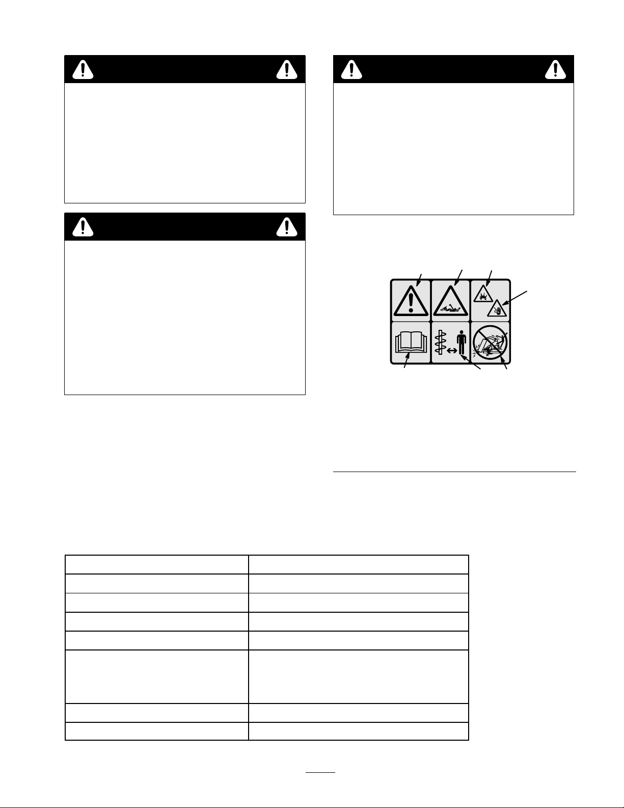
Decals
1
2
alert symbol
Read operator’s manual
Full body entanglement
Stay away from rotating
shafts and augers
#
3
99–9942
Figure 1
5.
6.
7.
.
5
4
7
Explosion hazard
Electric shock hazard
Do not dig in areas with
buried gas or power lines
ed by
6
Specifications
Note:
Specifications and design are subject to change without notice.
Width 16
Length
Height
W
eight (without auger)
Maximum auger diameter
Motor
Displacement
Rated pressure
Flow range
Drive ratio
Output shaft diameter
inches (40.64 cm)
24 inches (60.96 cm)
22 inches (55.88 cm)
176 lbs (79.8 Kg)
30 inches (76.2 cm)
1
1.9 in3/rev (28.93 cm3/rev)
3000 PSI Continuous (21
0–20 GPM (38–76 Lpm)
3.75:1
2.56 inches (6.5 cm)
1 Kg/cm2)
3
Page 4
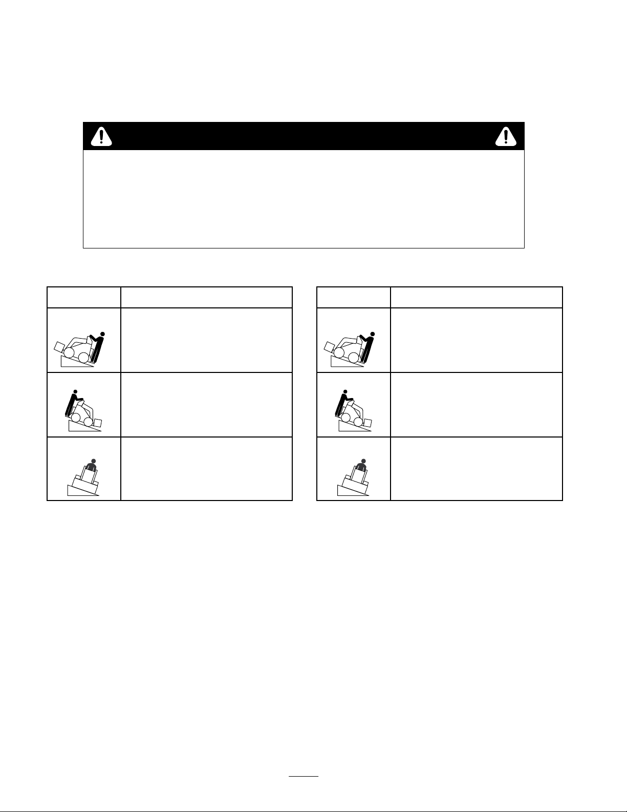
Stability
To
determine the degree of slope you can traverse with the auger installed on a traction unit, find the stability rating for the
hill position you want to travel in the appropriate table below
position in the Stability Data section of the traction unit operator’s manual.
Ratings
, then find the degree of slope for the same rating and hill
WARNING
POTENTIAL HAZARD
•
Exceeding the maximum slope can cause the traction unit to tip.
WHA
T CAN HAPPEN
•
If the traction unit tips, you or bystanders could be crushed.
HOW T
•
O AVOID THE HAZARD
Do not drive the traction unit on a slope steeper than the maximum slope.
Stability With a 30 inch Auger
Orientation
Front Uphill
Stability Rating
C
Rear Uphill
D
Side Uphill
C
IMPORTANT:
auger installed is rated for use with the counterweight.
Do not use it with a large auger without the
counterweight or the traction unit will become
unstable.
The auger drive head with a large
Stability Without an Auger
Orientation
Front Uphill
Stability Rating
D
Rear Uphill
C
Side Uphill
B
Note:
The auger drive head without an auger is rated for
use without the counterweight. If you use the
counterweight, the traction unit will be less stable in the
front and side uphill positions.
Stability With Augers Less Than 30
inches in Diameter
Augers
smaller than 30 inches in diameter will have
stabilities between the stability of the drive head alone
and the drive head with the 30 inch auger
12 inches will have a stability closer to the 30 inch auger
and should be used with the counterweight. Augers
smaller than 12 inches will have a stability closer to the
drive head alone and should be used without the
counterweight.
4
. Augers above
Page 5

Installation
Loose/Separate/Optional
DESCRIPTION QTY. USE
Auger
drive head
Auger (any size, sold separately)
Bolt, 7/8”–9 x 4–1/2”
Nut, 7/8”–9
Bolt, 5/8”–1
Nut, 5/8”–1
Auger extension (sold separately)
Bolt, 7/8”–9 x 4–1/2”
Nut, 7/8”–9
Rear stabilizer (sold separately)
Counterweight (sold separately)
Installing
the T
1 x 3–1/2”
1
the Drive Head on
raction Unit
Parts
1
1
1
1
2
2
1
1
1
1
1
Install on traction unit
Install auger on drive head
Install between drive head and auger
Recommended for use with small diameter
augers
Required for use with large diameter augers
1
IMPORTANT:
plates ar
Note:
Always use the traction unit to lift and move the
drive head. T
sling a strap over each end of the auger and hoist it to the
desired location.
1.
Ensure that the drive head is positioned on a level
surface with enough space behind it to accommodate
the traction unit.
2.
Move the pump control lever to the slow (turtle)
position the start the engine.
3.
Slowly push the attachment tilt lever forward to tilt the
mount plate forward.
4.
Position the mount plate into the upper lip of the
receiver plate on the drive head (Fig. 2).
Befor
e installing, ensur
e fr
ee of any dirt or debris.
o move an auger without the drive head,
e that the mount
2
Figure
1. Mount
5. Raise
IMPORTANT
to clear the gr
tilted all the way back.
6.
7.
plate
the loader arms while tilting back the mount
plate at the same time.
: The drive head should be raised enough
ound and the mount plate should be
Stop the engine.
Engage the quick attach pins (Fig. 3).
2
2.
Receiver plate
m–4055
5
Page 6

5.
Slide the collar back on the hydraulic coupler and
1
connect the attachment couplers to the traction unit
couplers.
Confirm that the connection is secure by pulling on the
6.
hoses.
1. Quick
attach pins (shown in engaged position)
Connecting
Figure
the Hydraulic
3
Hoses
WARNING
POTENTIAL
• Hydraulic fluid escaping under pressure
can penetrate skin and cause injury.
WHAT
• Fluid accidentally injected into the skin
must be surgically removed within a few
hours by a doctor familiar with this form of
injury or gangrene may result.
HOW TO AVOID THE HAZARD
• Keep body and hands away from pin hole
leaks or nozzles that eject high pressure
hydraulic fluid.
• Use cardboard or paper to find hydraulic
leaks, never use your hands.
HAZARD
CAN HAPPEN
m–4056
Installing
an Auger onto the
Drive Head
WARNING
POTENTIAL
•
The auger head swings fr
arms.
WHA
T CAN HAPPEN
•
Hands or fingers could get pinched and sever
injur
between the cradle arms and the swinging drive
head.
HOW T
•
Keep hands and fingers away fr
arms.
1.
Raise the loader arms so the drive head clears the
ground.
Stop the engine.
2.
3.
Manually rotate the auger drive head up, until you can
slide (2) 5/8”–1
sides of the cradle arms, securing the drive head.
Lightly secure each bolt with a 5/8”–1
2
HAZARD
eely in the cradle
ed or amputated if they ar
O AVOID THE HAZARD
1 x 3–1/2” bolts into the holes on both
e caught
om the cradle
1 nut (Fig. 4).
ely
3
1
1. Stop
2.
IMPORTANT
cleaned fr
connections.
3.
4.
the engine.
Move the auxiliary hydraulic lever forward, backward,
and back to neutral position to relieve hydraulic
pressure at the hydraulic couplers.
: Ensur
om hydraulic connections befor
Remove the protective covers from the hydraulic
couplers on the traction unit.
Connect the covers together to prevent contamination
during operation.
e that all for
eign matter is
e making
Figure
1. Drive
2.
4. If
6
head
Cradle arm
using an extension with the auger
the extension into the end of the auger and secure the
auger to the drive head with the 7/8”–9 x 4–1/2” bolt
and 7/8”–1
1 nut (Fig. 5).
4
3.
Bolts (5/8”–11 x 3–1/2”)
and nuts (5/8”–1
, insert the end of
m–3944
1)
Page 7

12.
3
When the auger is vertical, tilt the attachment plate
rearward, until the drive head contacts the attachment
plate to stabilize the auger and keep it from swinging
freely (Fig. 8).
1
4
Figure
1. Extension
2. Auger
5. Start
6.
shaft
the engine.
Maneuver the drive shaft into the end of the auger
2
5
3.
Bolt (7/8”–9 x 4–1/2”)
4.
Nut (7/8”–9)
shaft or extension (if applicable) (Fig. 6).
1
1. Drive
7. Stop
8.
head
the engine.
Secure the auger to the drive head with the 7/8”–9 x
4–1/2” bolt and 7/8”–1
9.
Remove the bolts and nuts from the cradle arms that
2
Figure
6
2.
1 nut (Fig. 7).
Auger shaft
were installed in step 3 (Fig. 7).
3
1
m–3971
m–3945
m–3948
Removing
Figure
an Auger/Extension
8
from the Drive Head
1. Raise
Note:
the drive head and the auger
the auger as high as possible and then move the traction
unit backward to pull the auger the rest of the way out of
the hole.
2.
3.
4.
5.
the loader arms so the auger comes out of the
hole.
If you have a 24 inch extension installed between
, it may be necessary to raise
Set the auger down in its storage location.
While lowering the arms, drive slowly backwards until
the auger is horizontal.
Stop the engine.
Remove the bolt and nut securing the drive head to the
auger or extension.
Figure
1. Bolt
(7/8”–9 x 4–1/2”)
2.
Nut (7/8”–9)
10.Start
11.
the engine.
Raise the auger free of the ground (Fig. 8).
7
3.
Bolts (5/8”–11 x 3–1/2”)
and nuts (5/8”–1
6.
Start the engine and back the traction unit away from
the auger
If an extension was used, remove the bolt securing it
2
m–3946
7.
and pull it of
Removing
the T
1)
1. Start
or onto a trailer
Stop the engine.
2.
3.
Disengage the quick attach pins by turning them to the
.
f of the auger
.
the Drive Head from
raction Unit
the engine and lower the drive head to the ground
.
outside.
7
Page 8

4.
Slide the collars back on the hydraulic couplers and
disconnect them.
IMPORTANT
point and teeth ar
: Do not use the auger unless the auger
e intact and in good condition.
IMPORTANT
to pr
event hydraulic system contamination during
storage.
Install the protective covers onto the hydraulic
5.
couplers on the traction unit.
6.
Start the engine, tilt the mount plate forward, and back
the traction unit away from the drive head.
: Connect the attachment hoses together
Operation
Digging
POTENTIAL
• Ther
telephone lines in the work ar
WHA
•
Shock or explosion may occur
HOW T
•
Have the pr
buried lines and do not dig in marked ar
IMPORTANT
is fr
ee of any trash or debris.
a Hole
DANGER
HAZARD
e may be buried power
T CAN HAPPEN
O AVOID THE HAZARD
operty or work ar
: Befor
e digging, ensur
, gas, and/or
ea.
.
ea marked for
eas.
e that the gr
ound
1.
Lower the auger to the soil at the site of the proposed
hole.
Move the throttle lever to fast (rabbit), the pump
2.
selector lever to slow (turtle), and the flow divider
control dial to the 10:00 o’clock position.
3.
Pull the auxiliary hydraulics lever backward to begin
drilling.
Lower the auger slowly as the soil is loosened. As you
4.
dig deeper
as required to keep the hole vertical (Fig. 9).
5. When
auger drive and lift the auger from the hole. Engage
the auger drive to spin of
digging.
Switching rapidly from forward to reverse will help
Note:
to shake of
, move the traction unit backward or forward
m–3950
Figure
the auger becomes full of soil, disengage the
f the soil.
9
f the soil, then resume
m–3951
Maintenance
Service
Service
Auger teeth–inspect
Planetary gear case oil–check
Planetary gear case oil–change
Chipped surfaces—paint
Interval Chart
Operation
Each
Use25Hours50Hours
X X
X
1000
Hours
X
Storage
Service
X
Notes
Replace if damaged
or worn
8
Page 9

CAUTION
POTENTIAL
•
If you leave the key in the ignition switch, someone could start the engine.
WHA
•
Accidental starting of the engine could seriously injur
HOW T
•
Remove the key fr
Checking
T CAN HAPPEN
Planetary Gear Case
HAZARD
O AVOID THE HAZARD
om the ignition switch befor
Oil
Check
the oil level in the planetary gear case every 25
hours and top of
Place the auger drive head on the ground so that the
1.
drive shaft is parallel with the ground.
2.
Rotate the drive head so that the oil drain plug is
located on top and the breather plug is on the bottom
(Fig. 10).
3.
Remove the oil drain plug (Fig. 10)
4.
Rotate the auger drive head so that the drain opening is
at the 2 o’clock position (Fig 10). Oil should just
begin to come out of the opening.
1
f the oil if necessary
.
e you or other bystanders.
e you do any maintenance.
6.
Replace the drain plug.
Changing
Planetary Gear Case
Oil
Change
every 1000 hours thereafter
requires 2 pints of a mild, extreme pressure lubricant,
rated API–GL–5, number 80 or 90.
1.
2.
3.
4.
the oil after the first 50 hours of operation and
. The planetary gear case
Support the drive head over an oil pan so that the oil
drain plug (Fig. 10) is on the bottom of the drive head,
facing the oil pan.
Remove the oil drain plug to drain the oil.
When the oil is completely drained, turn the drive
head so that the oil drain opening is on the top of the
drive head, facing the up.
Add 2 pints of a mild, extreme pressure lubricant,
rated API–GL–5, number 80 or 90.
2
Figure
1. Drain
5. If
plug
no oil comes out of the opening, add oil (a mild,
extreme pressure lubricant API–GL–5, number 80 or
90) until the oil starts to run out when the drain hole is
at the 2 o’clock position.
10
2.
Breather plug
m–4054
5.
Replace the drain plug.
Storage
1.
Before long term storage, wash the attachment with
mild deter
Check and tighten all bolts, nuts, and screws. Repair or
2.
replace any damaged or worn part.
3.
Ensure that all hydraulic couplers are connected
together to prevent contamination of the hydraulic
system.
Paint all scratched or bare metal surfaces. Paint is
4.
available from your Authorized Service Dealer
Store the attachment in a clean, dry garage or storage
5.
area. Cover it to protect it and keep it clean.
gent and water
.
.
9
Page 10

Troubleshooting
PROBLEM POSSIBLE
Drive head does not operate.
CAUSES
1.
Hydraulic coupler not
completely connected
2.
Defective hydraulic coupler
3.
An obstruction in a hydraulic
hose
4.
Kinked hydraulic hose
5.
Contamination in the gearbox
CORRECTIVE ACTION
1.
Check and tighten all couplers.
2.
Check couplers and replace
any that are defective.
3.
Find and remove the
obstruction.
4.
Replace the kinked hose
5.
Refer to your authorized
service dealer
.
10
Page 11

11
Page 12

 Loading...