

Page 1

CEKit
STX-26StumpGrinder
ModelNo.22368
Installation
LooseParts
Usethechartbelowtoverifythatallpartshavebeenshipped.
FormNo.3374-417RevB
InstallationInstructions
ProcedureDescription
1
2
3
4
Brakebar1
Locknut2
Mountinglink1
Flange-headshoulderbolt1
Idlerspring1
Flange-headnut(8mm)
Flange-headnut(9.5mm)
Longbolt1
Shoulderbolt
Hexnut3
Threadedrod1
Brakeyoke1
Brakeplate1
Brakehandle1
Hexheadshoulderbolt1
Hexsocket/hexheadshoulderbolt
Handlegrip1
Interlockrod1
Hairpincotter1
Controlspring
Washer1
Hydraulicmotorcover1
Bolt4
Decal107-84951
Decal121-44381
Qty.
Use
2
2
1
1
1
Installtheparkingbrake.
Installtheinterlockrod.
Installthehydraulicmotorcover.
Applythedecals.
©2012—TheToro®Company
8111LyndaleAvenueSouth
Bloomington,MN55420
Registeratwww.T oro.com.
OriginalInstructions(EN)
PrintedintheUSA.
AllRightsReserved
*3374-417*B
Page 2
1
InstallingtheParkingBrake
Partsneededforthisprocedure:
1Brakebar
2Locknut
1Mountinglink
1Flange-headshoulderbolt
1Idlerspring
2
Flange-headnut(8mm)
2
Flange-headnut(9.5mm)
1Longbolt
1
Shoulderbolt
3Hexnut
1Threadedrod
1Brakeyoke
1Brakeplate
1Brakehandle
1Hexheadshoulderbolt
1
Hexsocket/hexheadshoulderbolt
1Handlegrip
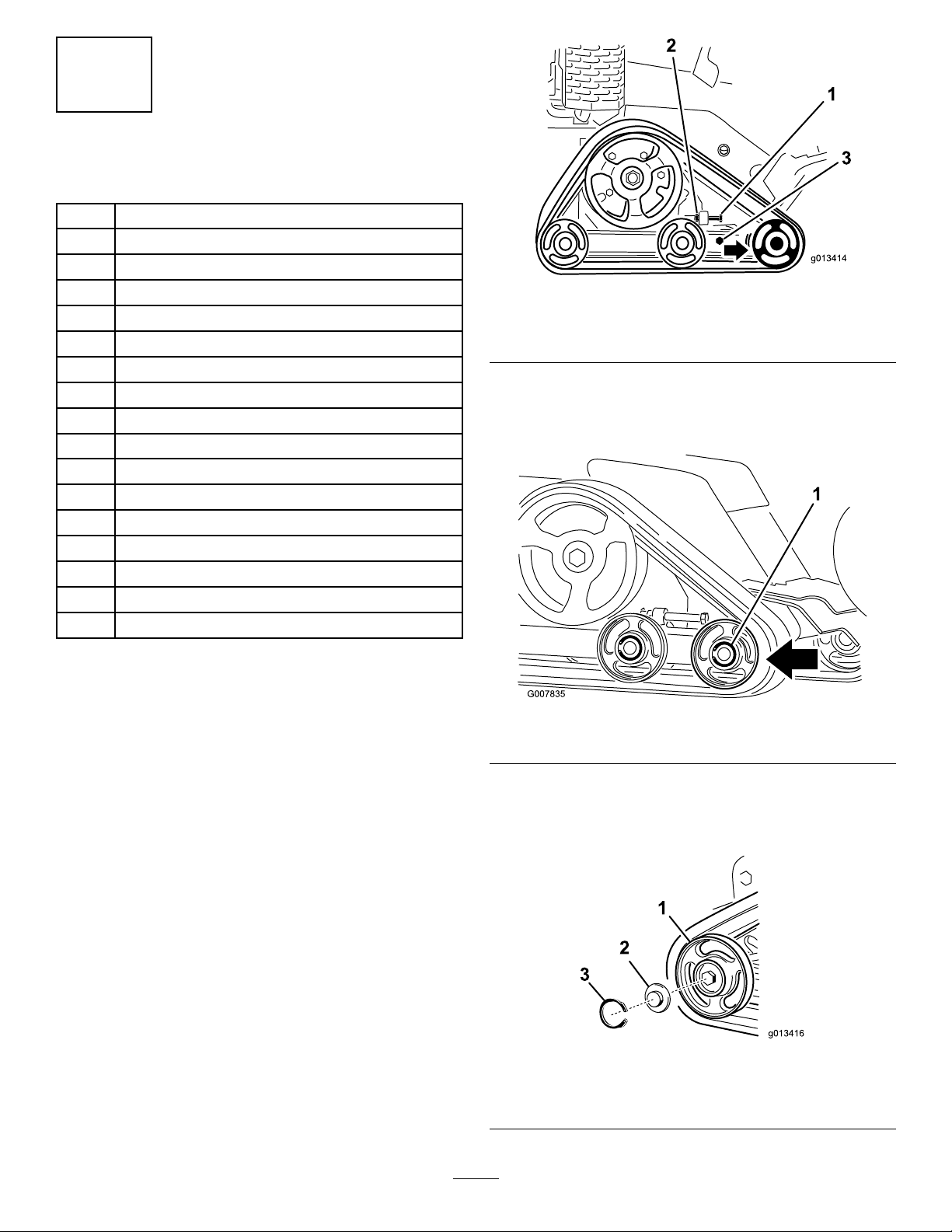
Figure1
1.Tensioningbolt
2.Jamnut
3.Clampbolts
5.Loosentheclampbolts(Figure1).
6.Pushthefrontroadwheelrearwardasfarasitwillgo
Figure2).
(
RemovingtheTrack
1.Lowerthegrinder.
2.Stoptheengine,removethekey ,andwaitforallmoving
partstostopbeforeleavingtheoperatingposition.
3.Lift/supporttherightsideoftheunitsothatthetrack
is3to4inches(7.6to10cm)offoftheground.
4.Backoutthetensioningboltandjamnut(Figure1).
Figure2
1.Frontroadwheel
7.Removetherear,outsideroadwheelasfollows:
A.Removethesnapringandcapfromthecenterof
theroadwheel(Figure3).
Figure3
1.Rearroadwheel
2.Cap
3.Snapring
2
Page 3
B.Removetheboltandgasketfromthecenterof
1
2
3
4
5
6
7
8
9
10
11
12
G018756
13
1
2
3
4
G019229
5
5
thewheelandpullthewheeloffofthemachine.
8.Removethetrack,beginningatthetopofthefront
roadwheel,peelitoffofthewheelwhilerotatingthe
trackforwards.
9.Repeatstep
7toremovetheinside,rearroadwheel.
InstallingtheBrake
1.Removethebottomshield.
2.Lineupthebrakebarwiththeslotslocatedbehindthe
tracksandslidethebarthroughfromrighttoleft.
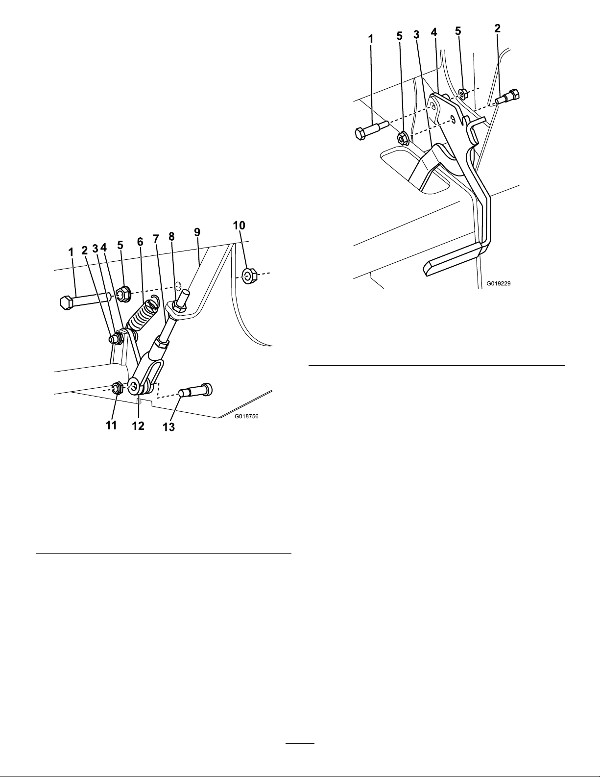
3.Connectthebrakeplatetothebrakeyokeusing3hex
nutsandthethreadedrod(Figure4).
Figure5
1.Shoulderbolt
2.Hexsocket/hexhead
shoulderbolt
3.Brakeplate
4.Brakehandle
5.Flange-headnut(8mm)
8.Slidethehandlegripontothebrakehandle.
9.Attachthebrakehandletotheunitwiththelong
shoulderscrewandaange-headnut(8mm)(Figure5).
10.Installthepreviouslyremovedbottomshield.
Figure4
1.Longbolt8.Hexnut
2.Flange-headshoulderbolt9.Brakeplate
3.Locknut
4.Mountinglink11.Locknut
5.Flange-headnut(9.5mm)
6.Idlerspring13.Hexheadshoulderbolt
7.Threadedrod
4.Attachthebrakeyoketothemountinglinkusingahex
headshoulderboltandlocknut(Figure4)androuteit
throughtheopeningunderthegastank.
10.Flange-headnut(9.5mm)
12.BrakeY oke
5.Connectthemountinglinkandidlerspringtothe
brakebarusingaange-headshoulderboltandlocknut
(
Figure4).
6.Attachtheremainingendoftheidlerspringtotheside
oftheunitwithalongboltand2ange-headnuts(9.5
mm)(Figure4).
7.Connectthebrakeplatetothebrakehandleusinga
hexsocket/hexheadshoulderboltandange-head
nut(8mm)(Figure5).
InstallingtheTrack
1.Installtheinside,rearroadwheelusingtheboltand
gasketremovedpreviously.Torquetheboltto75ft-lb
(102N-m)andthenclean,grease,andinstallthecap
andsnapring.
2.Beginningatthedrivesprocket,coilthetrackaround
thesprocket,ensuringthatthelugsonthetrackt
betweenthespacersonthesprocket(Figure2).
3.Pushthetrackunderandbetweenthefrontandcenter
roadwheels(Figure2).
4.Installtheoutside,rearroadwheelusingtheboltand
gasketremovedpreviously.Torquetheboltto75ft-lb
(102N-m)andthenclean,grease,andinstallthecap
andsnapring.
5.Installthetensioningboltandjamnut.
6.Torquethetensioningboltto24to30ft-lb(32.5to40
N-m)totightenthetrack.
7.Ensurethatthetrackdeectslessthan1/4to3/8inch
(0.6to1cm)when45lb(20.6kg)offorceisapplied
tothetrackspan.Adjustthetorqueonthetensioning
boltasneeded.
3
Page 4

8.Tightenthejamnut.
g019227
1 2
1
2
3
4
G018758
9.Tightentheclampboltsandtorqueto75ft-lb(102
N-m).
10.Lowerthemachinetotheground.
7.Installthebottomshield.
2
AdjustingtheHydraulicHoses
Thehydraulichosesunderthecontrolpanelabovethebrake
leverneedtobeorientedsothatthe45degreeelbowinthe
hosettingpointstotherightasshowninFigure6.Ifthey
arenot,loosenthehosettingsandorientandtorquethem
asshowninFigure6.
Figure6
1.Torqueto30ft-lb(40.6
N-m)
Checktheoperationofthebrakehandletoensurethatitdoes
notcontactthehoses.Ifitdoes,adjustthehosesfurtheror
useacabletietoholdthemawayfromthebrakehandle.
2.Torqueto42ft-lb(57N-m)
InstallingtheInterlockRod
Partsneededforthisprocedure:
1Interlockrod
1Hairpincotter
1
Controlspring
1Washer
Procedure
1.Inserttheinterlockrodthroughthebottomholenext
tothegrindercontrollever(Figure7).
Figure7
1.Interlockrod3.Washer
2.Controlspring
4.Hairpincotter
AdjustingtheParkingBrake
Pullupontheparkingbrakehandle.Youshouldstarttofeel
resistance(i.e.,thebrakebarcontactsthetrack)whenthe
handleisparalleltotheoorwhenviewedfromtheright
side.Ifcontactismadebeforeorafterthispoint,adjustthe
brakeasfollows:
1.Removethebottomshield.
2.Loosenthejamnutunderbrakeplateonthethreaded
brakeadjustmentrod(Figure4).
3.Liftthebrakehandlejustuntilthebrakebarcontacts
thetrack.
4.Tightenorloosenthejamnutabovethebrakeplateon
thethreadedrod(Figure4)asneededuntilthehandle
isparalleltotheoorwhenviewedfromtheside.
5.Tightenthejamnutunderthebrakeplatetosecure
thesetting(
6.Liftthebrakehandletotheengagedpositiontoensure
thatthebrakerodengagesthetrackandthatthehandle
popsupandisretainedintheengagedpositionagainst
themachineframe.
Figure4).
2.Slidethecontrolspringandwasherontotheinterlock
rod(Figure7).
3.Securethespringandwasherinplacewiththehairpin
cotter(Figure7).
3
InstallingtheHydraulicMotor Cover
Partsneededforthisprocedure:
1Hydraulicmotorcover
4Bolt
Procedure
Placethehydraulicmotorcoveroverthemotorandattachto
theframewith4bolts(
4
Figure8).
Page 5

1
2
G018759
Figure8
G018841
1
2
1.Bolts2.Hydraulicmotorcover
Figure9
4
ApplyingtheDecals
Partsneededforthisprocedure:
1Decal107-8495
1Decal121-4438
Procedure
1.Cleantheareawherethedecalswillbeplacedand
ensurethatitisfreeofdirt,grease,orotherforeign
material.
2.Removethebackingofthedecalsandplacethem
carefullyontheunitasshowninFigure9.
1.Decal107-84952.Decal121-4438
5
Page 6

Notes:
6
Page 7

Notes:
7
Page 8

 Loading...