

Page 1
FormNo.3422-426RevA
CEKit
Dingo
ModelNo.22366
®
323CompactToolCarrier
InstallationInstructions
Safety
SafetyandInstructional
Decals
Safetydecalsandinstructionsare
easilyvisibletotheoperatorandare
locatednearanyareaofpotential
danger.Replaceanydecalthatis
damagedormissing.
100-1692
1.Brakeengaged3.Brakedisengaged
2.Parkingbrake
Installation
LooseParts
Usethechartbelowtoverifythatallpartshavebeenshipped.
ProcedureDescription
1
2
3
4
Nopartsrequired
Nopartsrequired
Brakebar2
Brake-barbracket2
Flange-headbolt2
Brake-cablebracket2
Parking-brakecable1
Lockingcollarwithsetscrew2
Largespring1
Convolutedcabletube
Bolt(5/16x1inch)
Locknut(5/16inch)
decal100-1692
Qty.
–
–
1
4
4
Preparethemachine.
Removetherear-wheelhubs.
Assembletheparking-brakelocking
mechanism.
Installtheparking-brakelocking
mechanism.
Use
©2018—TheToro®Company
8111LyndaleAvenueSouth
Bloomington,MN55420
Registeratwww.T oro.com.
OriginalInstructions(EN)
PrintedintheUSA
AllRightsReserved
*3422-426*A
Page 2
ProcedureDescription
5
6
Parking-brakeleverassembly1
Clevispin(3/4inch)
Cotterpin(3/4inch)
Wheel-hubassembly2
Hublocknut2
Qty.
Use
1
1
Installtheparking-brakelever.
Installtherear-wheelhubs.
7
8
9
Nopartsrequired
Loader-valvelockassembly1
Self-tappingbolts(1/4x5/8inch)
Bolt(1/4x2inches)
Spacer
CE-informationdecal
1
PreparingtheMachine
NoPartsRequired
Procedure
1.Parkthemachineonalevelsurface.
2.Lowertheloaderarms.
3.Engagetheparkingbrake.
4.Shutofftheengineandremovethekey.
5.Raisethemachineoffthegroundandsupportit
usingjackstands.
Note:Usejackstandsratedforyourmachine.
RefertotheOperator’sManualforyourmachine
todeterminetheweight.
–
2
1
1
1
Adjusttheparkingbrake.
Installtheloader-valvelock.
InstalltheCE-informationdecal.
2
RemovingtheRear-Wheel Hubs
NoPartsRequired
Procedure
1.Removetherearwheels.
2.Removeanddiscardthelocknutssecuringthe
rear-wheelhubs.
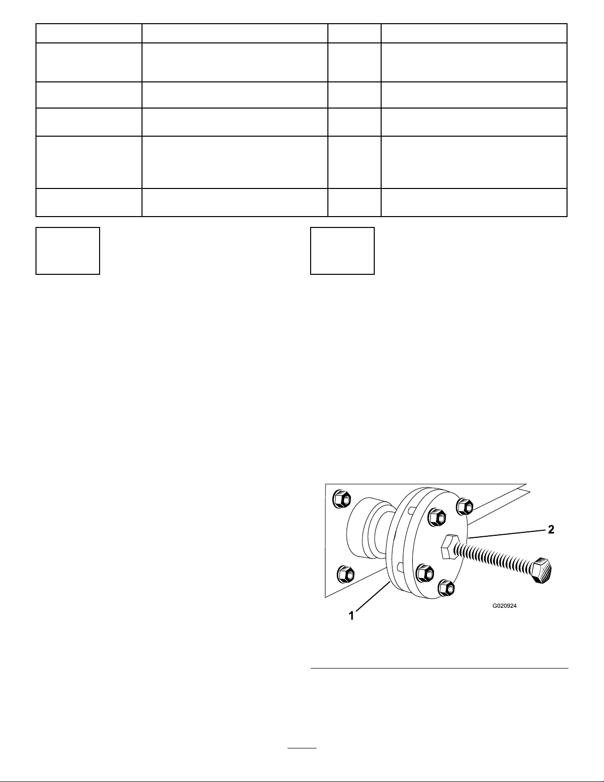
3.Usingahubpuller(K-LineSpecialServiceT ools,
partnumberTOR4096),removetherear-wheel
hubs(Figure1).
1.Hub2.Hubpuller
4.Savethekeyfromeachshaft.
2
g020924
Figure1
Page 3
3
Assemblingthe
Parking-BrakeLocking
Mechanism
Partsneededforthisprocedure:
2Brakebar
2Brake-barbracket
2Flange-headbolt
2Brake-cablebracket
1Parking-brakecable
2Lockingcollarwithsetscrew
1Largespring
Procedure
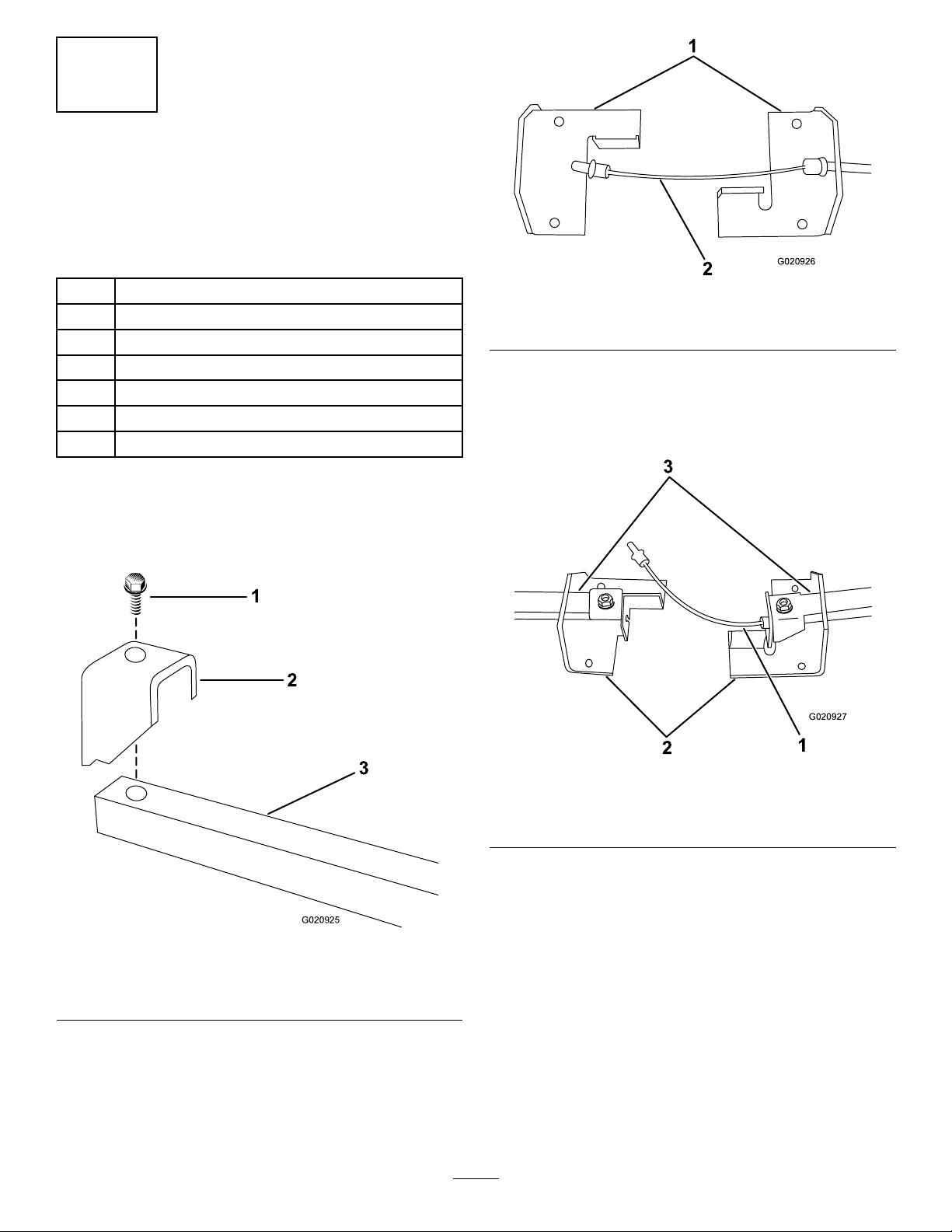
1.Fastenthebrake-barbracketstothebrakebars
using2bolts(Figure2).
g020926
Figure3
1.Brake-cablebracket2.Brakecable
3.Insertthecablethroughtherightbrake-cable
bracket(Figure3).
4.Slidethebrake-cablebarsthroughtheopenings
inthebrake-cablebrackets(Figure4).
Figure2
1.Bolt3.Brakebar
2.Brake-barbracket
2.Arrangethebrakecablebracketsonaat
surface(Figure3).
g020927
Figure4
1.Brakecable3.Brake-cablebar
2.Brake-cablebracket
5.Setthecableintotherightbrake-barbracket,
andsecureitrmlyinplacewithalockingcollar
andsetscrewassembly(Figure5).
g020925
3
Note:Thecablemustbesecurelyheldinthe
bracketwithnomovement.
Page 4
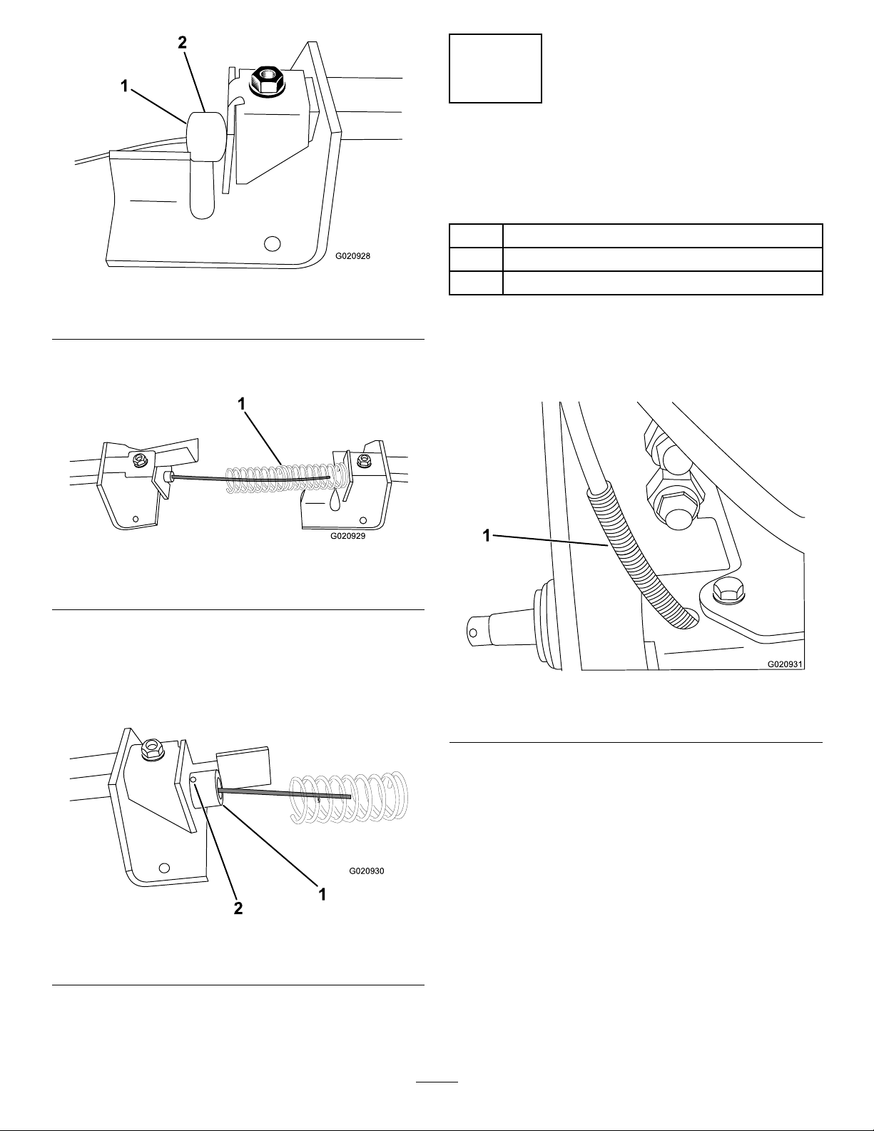
Figure5
4
InstallingtheParking-Brake LockingMechanism
Partsneededforthisprocedure:
1
Convolutedcabletube
4
g020928
4
Bolt(5/16x1inch)
Locknut(5/16inch)
1.Lockingcollar
6.Positionthelargespringoverthecable(Figure
6).
1.Largespring
7.Setthecableintotheleftbrake-barbracket,and
secureitwithalockingcollarandasetscrew
assembly(Figure7).
2.Setscrew
Figure6
Note:Thecablemustbesecurelyheldinthe
bracketwithnomovement.
Procedure
1.Slidetheconvolutedcabletubeoverthebrake
cable(Figure8).
g020929
g020931
Figure8
1.Parkingbrakecablewiththeconvolutedtube
1.Lockingcollar
Figure7
2.Setscrewassembly
2.Fromunderthemachine,routetheendofthe
cablethroughtheframeinthelower-leftcorner
oftheframe(Figure8).
Note:Ensurethatconvolutedcabletube
protrudesatleast10to15cm(4to6inches)
throughthehole.
3.Positionthebrakeassemblyunderthemachine
againstthebackoftheframewiththebrake
g020930
4
barsthroughtheholesinthesideoftheframe,
locatedinfrontofthewheelmotors(Figure9).
Page 5

5
InstallingtheParking-Brake Lever
Partsneededforthisprocedure:
1Parking-brakeleverassembly
1
Clevispin(3/4inch)
1
Cotterpin(3/4inch)
Procedure
Figure9
1.Rearwheelmotors
4.Securethebrakeassemblytotheframewiththe
4bolts(5/16x1inch)and4locknuts(5/16inch)
asshowninFigure9.
2.Bolts(5/16x1inch)
andlocknuts(5/16
inch)—fourthboltand
locknutnotvisible
Note:Y oumustpushtheboltsthroughthe
frameandthebrakecablebracketsfromthe
rearofthemachine.
g020932
1.Routethecableacrosstheparking-brakelever
assembly(Figure10).
Figure10
1.Parking-brakecable2.Parking-brakelever
assembly
2.Securethecabletotheleverwiththeclevispin
(3/4inch)andthecotterpin(3/4inch)asshown
inFigure11.
5
g020933
Page 6

Figure12
g020935
Figure11
1.Parking-brakelever3.Parking-brakecable
2.Clevispin(3/4inch)and
cotterpin(3/4inch)
3.Lightlytightenthenutsontheadjustmentcollar
aroundthebracketontheleverplate(Figure12).
1.Cablewithadjustment
nuts
g020934
4.Loosenthenutssecuringtheaircleanertothe
2.Bracketonthe
parking-brakelever
assembly
frame(Figure13).
Figure13
1.Air-cleanernuts2.Aircleaner
5.Slidetheboltsintheleverassemblyoverthe
air-cleanerboltsbetweentheframeandthe
air-cleanermounting-bracketasshowninFigure
14andFigure15.
6
g020936
Page 7

Figure15
g020938
Figure14
1.Leverassembly2.Lever-assemblyslots
1.Leverassembly3.Air-cleaner
mounting-bracket
g020937
2.Air-cleanerbolts
6.Withtheslotsintheplatepositionedoverthe
air-cleanerbolts,tightentheair-cleanernuts.
7
Page 8

6
InstallingtheRear-Wheel Hubs
Partsneededforthisprocedure:
2Wheel-hubassembly
2Hublocknut
Procedure
1.Cleantherear-driveshaftsandtheinsideofthe
taperedboreofthewheelhubswithalcoholora
degreaser(Figure16).
g020940
Figure17
1.Wheelhub(leftside)
5.Securethehubswithnewhublocknuts.
Figure16
1.Rear-driveshaft(leftside)
2.Disengagetheparking-brakelever.
3.Placethepreviously-removedkeysintotheslots
inthedriveshafts.
4.Placethenewwheelhubsontothedriveshafts
(Figure17).
6.Torquethenutsto406to474N∙m(300to350
ft-lb).
7.Installtherearwheels.
8.Torquethewheellugnutsto68N∙m(50ft-lb).
g020939
8
Page 9

7
AdjustingtheParking Brake
NoPartsRequired
Procedure
1.Pushtheparking-brakeleverupandforwardto
disengageit.
2.Checkthebrakebarsprotrudingfromeitherside
ofthemachine.
Note:Thebarsshouldbeabout3mm(1/8
inch)fromthewheelhubandneitherbarshould
beabletomovesidetoside.
3.Pulltheparking-brakeleverdowntoengageit.
Note:Thebarsshouldslideintothenotches
inthewheelhub.
4.Ifthebrakebarsmove,aretooclosetothe
wheelwhendisengaged,ordonotfullyengage
theslotsinthewheelhubwhenengaged,
correctitbyadjustingthe2adjustmentnutson
thecable(Figure12).
Figure18
1.Loader-valvelock
2.Removetheboltsecuringtheleftleverand
replaceitwiththebolt(1/4x2inches)andthe
spacer(Figure19).
2.Self-tappingbolts(1/4x
5/8inch)
g003566
8
InstallingtheLoader-Valve Lock
Partsneededforthisprocedure:
1Loader-valvelockassembly
2
Self-tappingbolts(1/4x5/8inch)
1
Bolt(1/4x2inches)
1
Spacer
Procedure
1.Using2self-tappingbolts(1/4x5/8inch),
looselyinstalltheloader-valvelockbehindthe
controllevers(Figure18).
Note:Theloadervalvelockshouldbeableto
slideforwardandbackwardintheslots.
g003597
Figure19
1.Bolt(1/4x2inches)2.Spacer
9
Page 10

3.Rotatetheloader-valvelockrearwardasshown
inFigure20.
Figure20
1.Loader-valvelock
4.Slidetheloader-valvelockrearwarduntilit
contactstheloaderarmandattachment-tilt
levers.
5.Tightentheself-tappingbolts(1/4x5/8inch)to
securetheloadervalvelock.
6.Pushforwardontheloaderarmand
attachment-tiltlevers.
9
InstallingtheCE-Compliant Decals
Partsneededforthisprocedure:
1
CE-informationdecal
Procedure
Installthedecalsontheleftsideofthemachine,near
g020941
thereartire.
1.Cleantheareawhereyouwillinstallthedecal.
2.Dampentheareawithwaterormildly-soapy
water.
3.Peelthedecalfromthebackingandinstallitin
place.
4.Squeegeeacrossthesurfaceofthedecal,
startingatthecenterofthedecalandworking
towardtheedgesusingoverlappingstrokes.
Note:Theyshouldnotmoveforwardatall.
Note:Iftheydo,loosentheself-tappingbolts
(1/4x5/8inch)andrepeatsteps4through6.
Important:Youwillneedtomovethe
leversrearwardtoengageordisengagethe
loader-valvelock.Theloader-valvelock
musttouchtheleverswhenitisdownand
theleversarereleased.
g249999
Figure21
1.CE-informationdecal
10
Page 11

Notes:
Page 12

 Loading...