


CE Kit
For Dingo® 320-D Compact Utility Loaders with
260000001 and Higher Serial Numbers
Model No. 22365
Loose Parts
Use the chart below to verify that all parts have been shipped.
Form No. 3354-736 Rev C
Installation Instructions
Step
1
2
3
4
5
6
7
8
No parts required
No parts required
Brake bar
Brake bar bracket
Flange-head bolt
Brake bracket
Parking brake cable
Locking collar with set screw
Large spring
Convoluted cable tube
Bolt (5/16 x 1 inch)
Locknut (5/16 inch)
Parking brake lever assembly
Clevis pin (3/4 inch)
Cotter pin
Wheel hub assembly
Hub locknut
No parts required
Loader valve lock assembly
Self-tapping screws (1/4 x 5/8 inch)
Bolt (1/4 x 2 inches)
Spacer
Description
Qty.
–
–
2
2
2
2
1
2
1
1
4
4
1
1
3/4 inch
2
2
–
1
2
1
1
Prepare the traction unit.
Remove the rear wheel hubs.
Assemble the parking brake locking
mechanism.
Install the parking brake locking
mechanism.
Install the parking brake lever.
Install the rear wheel hubs.
Adjust the parking brake.
Install the loader valve lock.
Use
© 2006—The Toro® Company
8111 Lyndale Avenue South
Bloomington, MN 55420
Register at www.Toro.com. Original Instructions (EN)
Printed in the USA.
All Rights Reserved
Step
Auxiliary hydraulics lever gate
Spacer 2
Lever mount block
Thick washer
Lock washer (5/16 inch)
Flange-head bolt (8 x 20 mm)
Auxiliary hydraulics lever
9
10
Carriage bolt (1/4 x 2 inches)
Locknut (1/4 inch)
Torsion spring
Self-tapping screw (1/4 x 1-3/8
inches)
Lock washer (1/4 inch)
Nut (1/4 inch)
No parts required
Description
Qty.
1
1
1
1
1
1
2
2
1
1
1
1
–
Install the auxiliary hydraulics lever
gate.
Adjust the high-speed throttle
setting to 3200 rpm.
Use
11
12
13
Self-tapping screw (5/16 x 3/4 inch)
CE information decal, 108-9738
European noise decal, 108-4725
Danger decal, 100-1701
Caution decal, 100-1702
Speed limiter decal, 100-1703
Control panel decal, 108-9733
Pinch decal, 100-8821
No rider decal, 100-8822
Hydraulic oil decal, 93-6686
Radiator cap decal, 106-5976
Delaration of Conformity
Step
1
Preparing the Traction Unit
1
1
1
1
1
1
1
4
2
1
1
1
Secure the rear access cover.
Install the CE compliant decals.
Obtain an Operator’s Manual.
Step
2
Removing the Rear Wheel
No Parts Required
Procedure
1. Stop the engine , lo w er the loader ar ms , and
remo v e the k ey .
2. Hoist the rear of the traction unit off of the
g round and secure it with jac k stands under the
frame so that y ou can safely w ork under it and
remo v e the rear wheels .
Hubs
No Parts Required
Procedure
1. R emo v e the rear wheels .
2. R emo v e and discard the loc kn uts securing the
rear wheel hubs .
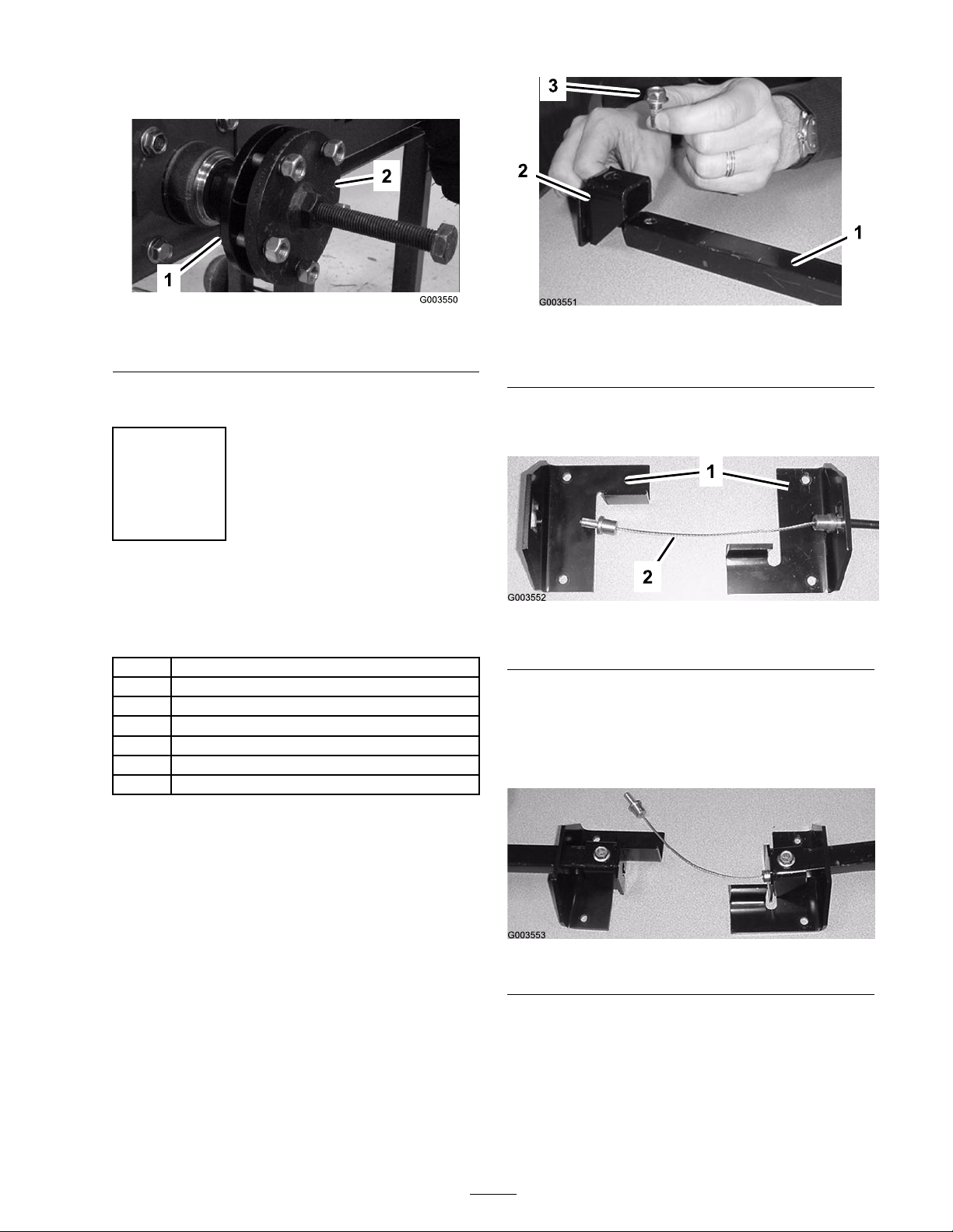
3. Using a hub puller (Ow atonna T ool Company
(OTC) par t n umber TOR4096), remo v e the
rear wheel hubs ( Figure 1 ).
2
Note: Y ou can contact OTC at
www .OTCtools .com .
Figure 1
1. Hub 2. Hub puller
4. Sa v e the k ey from eac h shaft.
Step
3
Assembling the Parking
Brake Locking Mechanism
Parts needed for this step:
2
Brake bar
2
Brake bar bracket
2
Flange-head bolt
2
Brake bracket
1
Parking brake cable
2
Locking collar with set screw
1
Large spring
Figure 2
1. Brake bar 3. Flange-head bolt
2. Brake bar bracket
2. Ar rang e the brak e brac k ets on a table as sho wn
in Figure 3 .
Figure 3
1. Brake brackets 2. Brake cable
3. Inser t the cable through the right brak e brac k et
as sho wn in Figure 3 .
4. Slide the bars through the openings in the
brak e brac k ets as sho wn in Figure 4 .
Procedure
1. F asten the brak e bar brac k ets to the brak e bars
using 2 flang e-head bolts ( Figure 2 ).
Figure 4
5. Set the cable into the right brak e bar brac k et,
and secure it fir mly in place with a loc king
collar and set screw assembly ( Figure 5 ). T he
cable m ust be securely held in the brac k et with
no mo v ement at all.
3
Step
4
Installing the Parking Brake
Locking Mechanism
Parts needed for this step:
Figure 5
1. Locking collar
2. Set screw
6. P osition the larg e spring o v er the cable ( Figure
6 ).
Figure 6
1. Large spring
7. Set the cable into the left brak e bar brac k et,
and secure it fir mly in place with a loc king
collar and set screw assembly ( Figure 7 ). T he
cable m ust be securely held in the brac k et with
no mo v ement at all.
1
Convoluted cable tube
4
Bolt (5/16 x 1 inch)
4
Locknut (5/16 inch)
Procedure
1. Slide the con v oluted tube o v er the brak e cable
( Figure 8 ).
2. F rom under the mac hine , route the end of
the cable through the frame in the lo w er left
cor ner of the frame ( Figure 8 ). Ensure that the
con v oluted tube protr udes at least 4 to 6 in.
(10 to 15 cm) through the hole .
1. Locking collar
Figure 7
Figure 8
1. Parking brake cable with the convoluted tube
3. P osition the brak e assembly under the traction
unit ag ainst the bac k w all of the frame with
2. Set screw
the brak e bars through the rectangular holes in
the sides of the frame , located in front of the
wheel motors ( Figure 9 ).
4
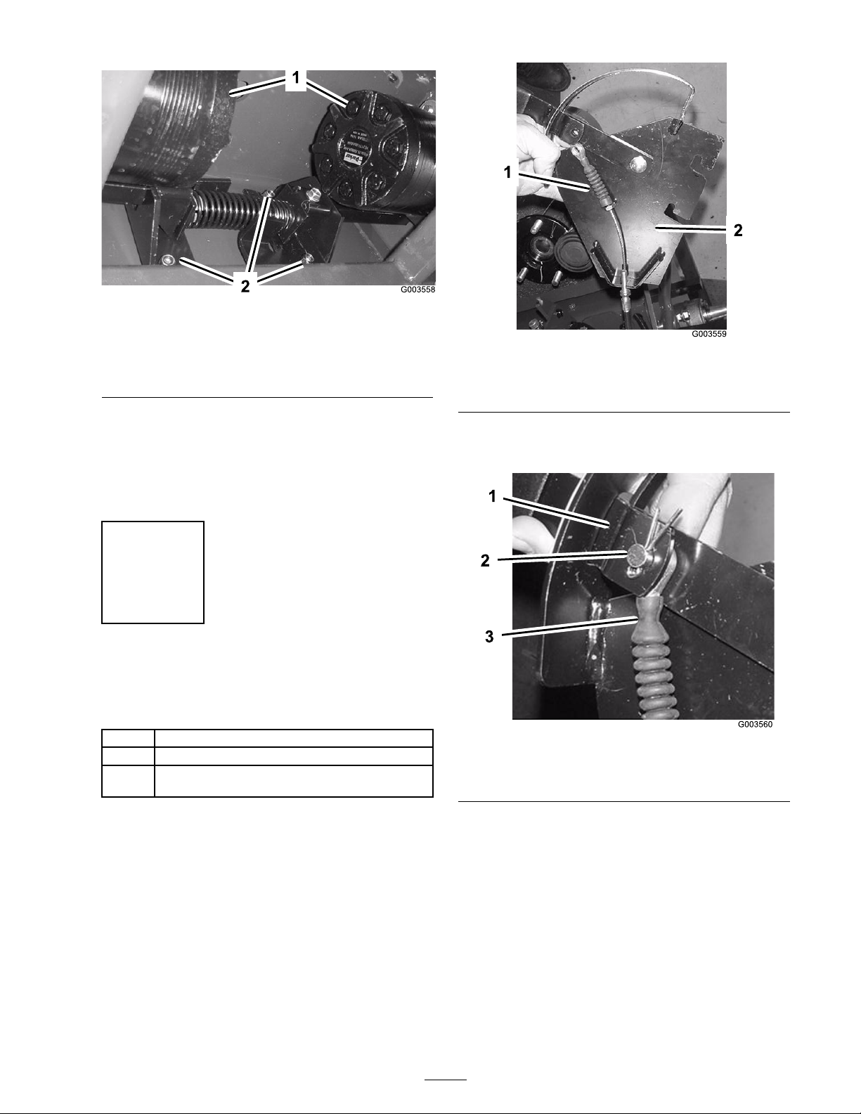
Figure 9
1. Rear wheel motors
2. Bolts (5/16 x 1 inch)
and locknuts (5/16 inch)
(fourth bolt and locknut
not visible)
4. Secure the brak e assembly to the frame with
4 bolts (5/16 x 1 in.) and loc kn uts (5/16
in.) ( Figure 9 ). T he bolts should be pushed
through the frame and brak e brac k ets from the
rear of the mac hine .
Step
5
Installing the Parking Brake
Lever
Parts needed for this step:
Figure 10
1. Parking brake cable 2. Parking brake lever
assembly
2. Secure the cable to the lev er with a clevis pin
and cotter pin (3/4 in.) ( Figure 11 ).
1
Parking brake lever assembly
1
Clevis pin (3/4 inch)
3/4
inch
Cotter pin
Procedure
1. R oute the cable across the parking brak e lev er
assembly ( Figure 10 ).
Figure 11
1. Parking brake lever 3. Parking brake cable
2. Clevis pin and cotter pin
3. Lightly tighten the n uts on the adjustment
collar around the brac k et on the lev er plate
( Figure 12 ).
5
 Loading...