

Page 1

CE Kit
Dingo 322 (with serial number 210000001 & Up) and
323 Compact Utility Loaders
Model No. 22364
Installation Instructions
Loose Parts
Note: Use the chart below to identify parts for assembly.
Description Qty. Use
Form No. 3327-840
Brake bracket
Brake bar
Brake bar bracket
Flange-head bolt
Parking brake cable
Convoluted cable tube
Locking collar with set screw
Large spring
Bolt, 5/16 x 1 in.
Locknut, 5/16 in.
Parking brake lever assembly
Clevis pin, 3/4 in.
Cotter pin, 3/4 in.
Wheel hub assembly
Cotter pin, 1-1/2 in.
Loader valve lock assembly
Self-tapping screw, 1/4 x 5/8 in.
Auxiliary hydraulics lever gate
Spacer
Lever mount block
Thick washer
Lock washer, 5/16 in
Flange-head bolt, 8 x 20 mm
Auxiliary hydraulics lever
Carriage bolt, 1/4 x 2 in.
Locknut, 1/4 in.
Torsion spring
Self-tapping screw, 1/4 x 1-3/8 in.
Lock washer, 1/4 in.
Nut, 1/4 in.
2
2
2
2
1
1
2
1
4
4
1
1
1
2
2
1
2
1
2
1
1
1
1
1
2
2
1
1
1
1
Installing the parking brake
Installing the loader valve lock
Installing the auxiliary hydraulics lever gate
Self-tapping screw, 5/16 x 3/4 in. 1 Securing the rear access panel
2003 by The Toro Company
8111 Lyndale Avenue South
Bloomington, MN 55420-1196
1
All Rights Reserved
Printed in the USA
Page 2
Description UseQty.
CE information decal (model 22305), 105-8415
CE information decal (model 22312), 105-8425
European Noise decal, 105–8405
Danger decal, 100-1701
Caution decal, 100-1702
Speed limiter decal, 100-1703
Control panel decal, 100–8824
Information decal, 104–6109
Pinch decal, 100-8821
No rider decal, 100-8822
Hydraulic oil decal, 93-6686
Operator’s Manual
Parts Catalog
Preparing the Traction Unit
1. Stop the engine, lower the loader arms, and remove the
key.
2. Hoist the traction unit off of the ground and secure it so
that you can safely work under it and remove the rear
wheels.
1
1
1
1
1
1
1
1
4
2
1
1
Installing the CE decals
Replace the
supplement the
Operator’s Manual
Parts Catalog.
and
2
Installing the Parking Brake
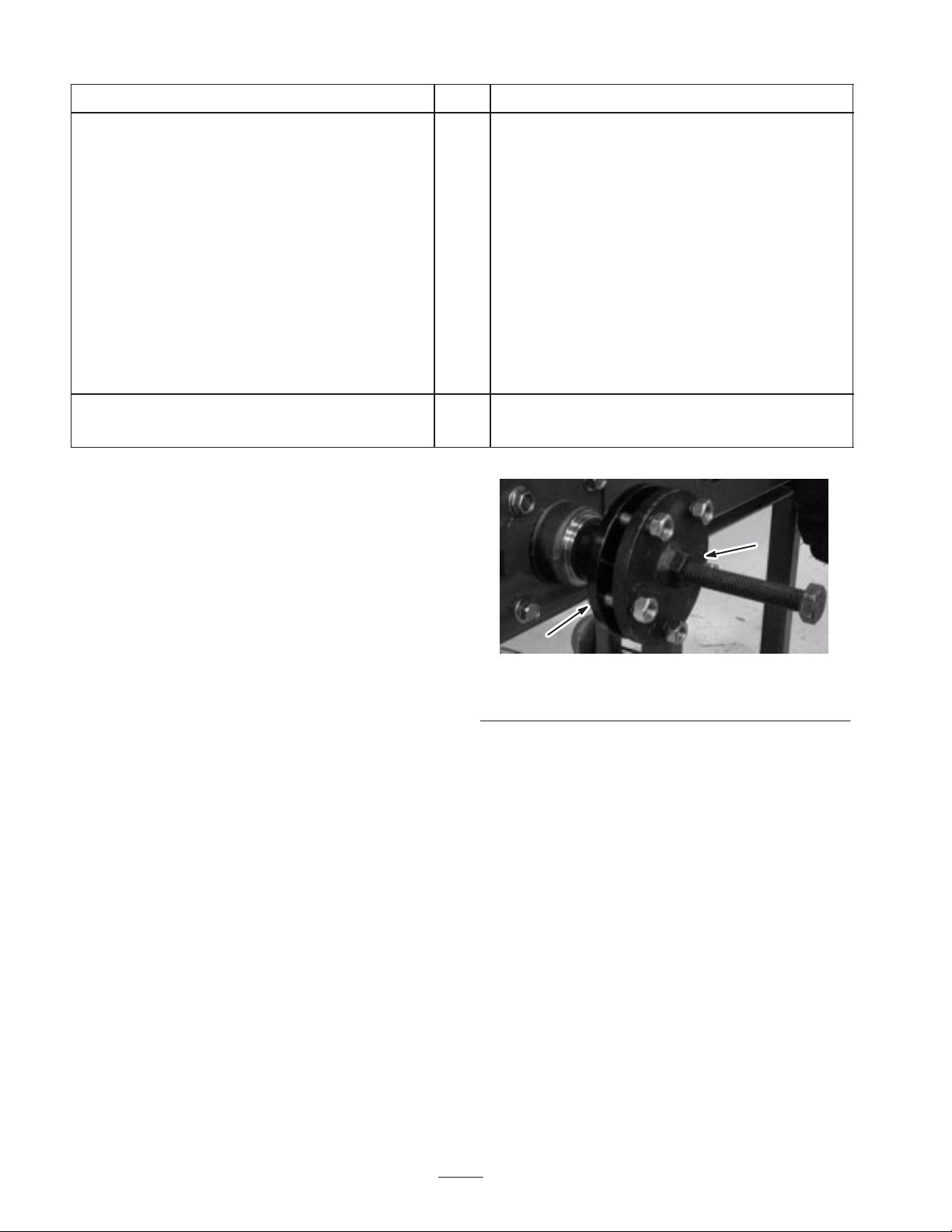
Removing the Rear Wheel Hubs
1. Remove the rear wheels.
2. Remove the cotter pins and crown nuts securing the rear
wheel hubs. Save the crown nuts for future use.
3. Using a hub puller (OTC part number TOR4096),
remove the rear wheel hubs (Fig. 1).
Note: You can contact OTC at (507) 455–7346.
1
Figure 1
1. Hub 2. Hub puller
4. Save the key from each shaft.
Assembling the Locking Mechanism
1. Fasten the brake bar brackets to the brake bars using 2
flange-head bolts (Fig. 2).
2
Page 3
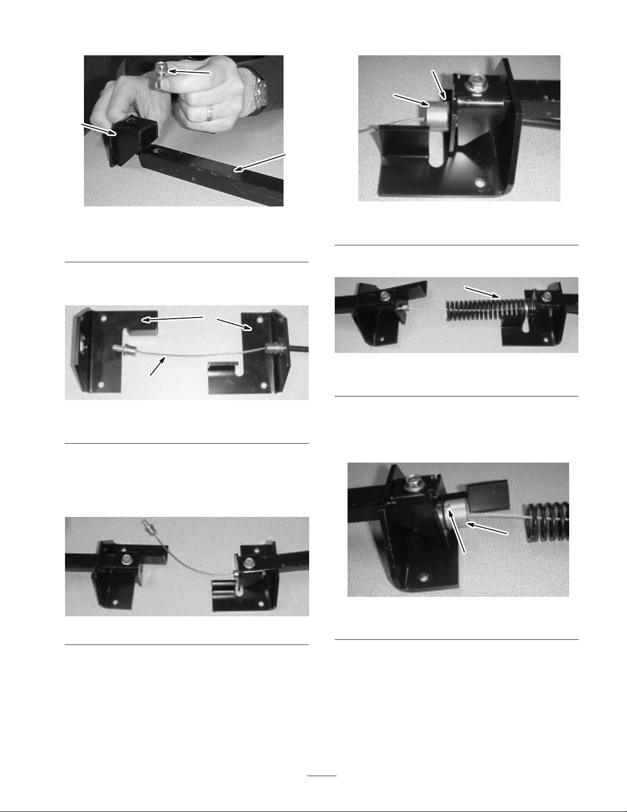
3
2
1
2
1
Figure 2
1. Brake bar
2. Brake bar brackets
3. Flange-head bolt
2. Arrange the brake brackets on a table as shown in
Figure 3.
1
GRAPHIC #
2
Figure 3
1. Brake brackets 2. Brake cable
3. Insert the cable through the right brake bracket as
shown in Figure 3.
4. Slide the bars through the openings in the brake
brackets (Fig. 4).
Figure 5
1. Locking collar 2. Set screw
6. Position the large spring over the cable (Fig. 6).
1
Figure 6
1. Large spring
7. Set the cable into the left brake bar bracket, and secure
it firmly in place with a locking collar and set screw
assembly (Fig. 7). The cable must be securely held in
the bracket with no movement at all.
Figure 4
5. Set the cable into the right brake bar bracket, and secure
it firmly in place with a locking collar and set screw
assembly (Fig. 5). The cable must be securely held in
the bracket with no movement at all.
1
2
Figure 7
1. Locking collar 2. Set screw
Installing the Locking Mechanism
1. Slide the convoluted tube over the brake cable (Fig. 8).
3
Page 4
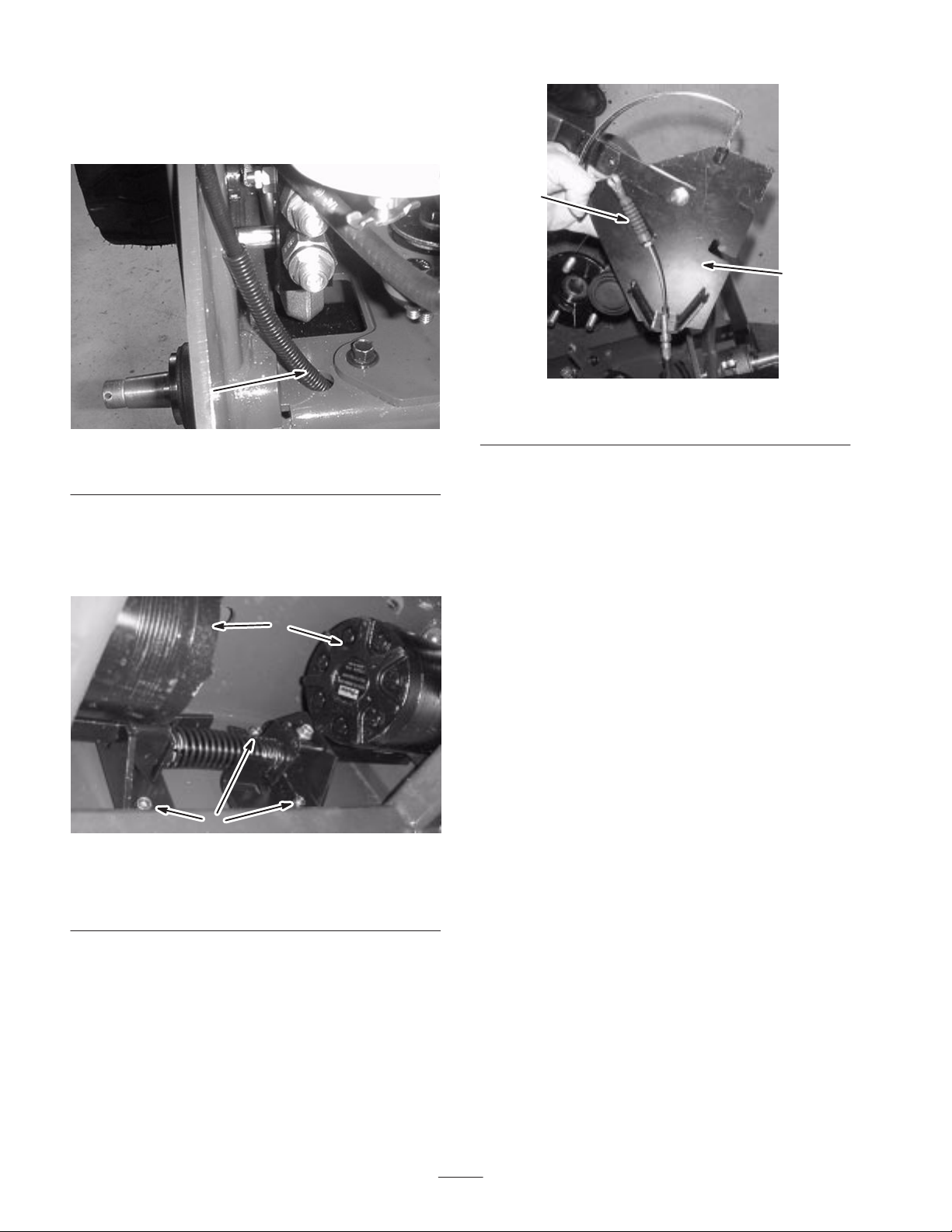
2. From under the machine, route the end of the cable
through the frame in the lower left corner of the frame
(Fig. 8). Ensure that the convoluted tube protrudes at
least 4 to 6 in. (10 to 15 cm) through the hole.
1
2
1
Figure 8
1. Parking brake cable with the convoluted tube.
3. Position the brake assembly under the traction unit
against the back wall of the frame with the brake bars
through the rectangular holes in the sides of the frame
(Fig. 9).
1
2
Figure 10
1. Parking brake cable 2. Parking brake lever plate
Figure 9
1. Rear wheel motors
2. Bolts and locknuts, 5/16 x 1 in. (fourth bolt and locknut not
visible)
4. Secure the brake assembly to the frame with 4 bolts
(5/16 x 1 in.) and locknuts (5/16 in.) (Fig. 9). The bolts
should be pushed through the frame and brake brackets
from the rear of the machine.
Installing the Parking Brake Lever
1. Route the cable across the parking brake lever plate
(Fig. 10).
4
Page 5

2. Secure the cable to the lever with a clevis pin and cotter
pin (3/4 in.) (Fig. 11).
1
2
3
2
1
Figure 13
1. Air cleaner bolts and nuts 2. Air cleaner
Figure 11
1. Parking brake lever
2. Clevis pin and cotter pin
3. Parking brake cable
3. Lightly tighten the nuts on the adjustment collar around
the bracket on the lever plate (Fig. 12).
1
2
Figure 12
1. Cable with adjustment
nuts
2. Bracket on the parking
brake lever plate
5. Slide the slots in the lever plate over the air cleaner
bolts, between the frame and the air cleaner mounting
bracket (Fig. 13).
Figure 14
4. Loosen the nuts securing the air cleaner to the frame
(Fig. 13).
6. With the slots in the plate positioned all the way over
the air cleaner bolts, tighten the air cleaner nuts.
5
Page 6

Installing the Rear Wheel Hubs
1. Thoroughly clean the rear drive shafts and the inside of
the tapered bore of the wheel hubs with alcohol or
degreaser (Fig. 15).
7. Install a new cotter pin (1-1/2 in.) through the end of
each drive shaft to secure the crown nuts.
8. Install the rear wheels.
9. Torque the wheel lug nuts to 50 ft-lb. (68 N⋅m).
Adjusting the Parking Brake
1
Figure 15
1. Rear drive shaft (left side)
2. Disengage the parking brake lever.
3. Place the keys removed previously into the slots in the
drive shafts.
4. Place the new wheel hubs with the lugs pointing out
over the drive shafts (Fig. 16).
1. Push the parking brake lever all the way up and forward
to disengage it.
2. Check the brake bars protruding from either side of the
traction unit. The bars should be about 1/8 in. (0.3 cm)
from the wheel hub and neither bar should be able to
move side to side.
3. Pull the parking brake lever down to engage it. The
bars should slide all the way into the notches in the
wheel hub.
4. If the brake bars move, are too close to the wheel hub
when disengaged, or do not fully engage the slots in the
wheel hub when engaged, correct it by adjusting the
two jam nuts on the cable (Fig. 12).
Installing the Loader Valve
Lock
1. Using 2 self–tapping screws (1/4 x 5/8 in.), loosely
install the loader valve lock behind the control levers
(Fig. 18). The loader valve lock should be able to slide
forward and back in the slots.
1
Figure 16
1. Rear wheel hub (left side)
5. Secure the hubs with the crown nuts you removed
previously.
6. Torque the crown nuts to 200 to 300 ft-lb. (270 to
400 N⋅m).
m-6026
1. Loader valve lock,
engaged
2. Rotate the loader valve lock rearward as shown in
Figure 18.
2
Figure 17
2. Self-tapping screws, 1/4 x
5/8 in.
1
6
Page 7

11
8
7
9
1
14
2
m-6025
Figure 18
3. Slide the loader valve lock rearward until it contacts the
the loader arm and attachment tilt levers. Hold it tightly
against the levers.
4. Tighten the screws to secure the loader valve lock.
5. Push forward on the loader arm and attachment tilt
levers. They should not move forward at all. If they
do, loosen the screws and repeat steps 3 through 5.
Note: You will need to move the levers rearward to engage
or disengage the valve lock. The lock must touch the levers
when it is all the way down and the levers are released.
Installing the Auxiliary
Hydraulics Lever Gate
1. Remove and discard decal number 98-4677 (Fig. 19)
from the frame near the auxiliary hydraulics lever.
10
6
12
3
15
4
13
m-6023
5
Figure 20
1. Auxiliary hydraulics valve
2. Auxiliary hydraulics valve
lever gate
3. Bolt
4. Spacer
5. Locknut
6. Lever mount block
7. Flange-head bolt, 8 x
20 mm
8. Lock washer, 5/16 in.
9. Thick washer
10. Carriage bolt, 1/4 x 2 in.
11. Auxiliary hydraulics lever
12. Locknut, 1/4 in.
13. Lever spring
14. Self-tapping screw, 1/4 x
1-3/8 in.
15. Lock washer and nut,
1/4 in.
3. Remove and discard the auxiliary hydraulics lever from
the valve.
4. Apply grease to the inside of the hole in the lever mount
block (Fig. 20).
Figure 19
2. Remove the 2 bolts, locknuts, and spacers securing the
auxiliary hydraulics valve to the frame (Fig. 20).
Discard the spacers.
5. Seat and install the lever mount block on the valve and
secure it using a thick washer, lock washer (5/16 in.),
and flange-head bolt (8 x 20 mm) (Fig. 20).
6. Install the auxiliary hydraulic lever gate under the valve
body and secure it to the valve and frame using 2 new
spacers and the bolts and locknuts removed previously
(Fig. 20).
Important Take care while installing the spacers and
nuts not to drop them into the traction unit.
7. Thread the new auxiliary hydraulics lever though the
opening in the gate and secure it loosely to the side of
the mount block with 2 carriage bolts (1/4 x 2 in.) and
locknuts (1/4 in.) (Fig. 20). Before tightening the nuts
completely, adjust the height of the lever to the level of
the handle of the traction unit with the lever all the way
forward in the furthest right hand slot of the gate.
8. Tighten the nuts.
9. Install the lever spring between the lever and the gate
(Fig. 20).
7
Page 8

10.Install the self-tapping screw (1/4 x 1-3/8) into the hole
a c ossba
on top of the gate (Fig. 20).
11. Adjust the screw so that when you push the auxiliary
hydraulics lever forward in the center slot, it contacts
the screw just before it goes into the detent position.
12.Secure the screw with a lock washer (1/4 in.) and nut
(1/4 in.) (Fig. 20).
13.Start the engine and set the throttle to the Fast position.
14.Push the lever forward into the center slot and release it.
It should travel back to the neutral position on its own.
15.If the lever stays in the detent position, adjust the screw
until it returns to the neutral position on its own.
16.Stop the engine and remove the key.
Installing the Decals
Install the decals in the positions indicated in the following table. Place each decal directly over the US English decal that
corresponds to the CE decal you are installing.
Note: Decals 105-8425, 105-8415, 105-8405, and 100-8822 do not have an US English equivalent installed on the traction
unit.
1. Thoroughly clean the area where you will install the
decal.
2. Dampen the area with water or mildly soapy water.
3. Peel the decal from the backing and install it in place.
Location US English CE
On the loader
arm crossbar
98-4682 100-1702
By the speed
limiter
98-8220 100-1703
By the hydraulic
oil fill tube
105-8404 93-6686
4. Squeegee across the surface of the decal, starting at the
center of the decal and working toward the edges using
overlapping strokes.
4 locations on the
loader arms
100-6141 100-8821
On the thigh
support
104-6108 104-6109
8
Page 9
Location CEUS English
On the inside of
On the control
On the inside of
the loader arm.
2 locations on the
loader arm
crossbar: one
facing the
operator and one
facing forward
98-9051 (US English)
100-1701 (CE)
100-8822
On the control
panel
99-3157 (US English)
100-8824 (CE)
9
Page 10

Location CEUS English
On the left side of
the frame under
the fuel tank
105-8415 (model 22305) or 105-8425
(model 22312)
On the left side of
the frame under
the fuel tank
105-8405
10
Page 11

11
Page 12

 Loading...