


TX700CompactToolCarrier
22351,22351G,22352
KompakterWerkzeugträgerTX700
22351,22351G,22352
Porte-outilcompactTX700
22351,22351G,22352
TX700compactewerktuigdrager
22351,22351G,22352
FormNo.3447-210RevA
www.T oro.com.
*3447-210*

FormNo.3439-258RevA
TX700CompactToolCarrier
ModelNo.22351—SerialNo.400000000andUp
ModelNo.22351G—SerialNo.400000000andUp
ModelNo.22352—SerialNo.400000000andUp
Registeratwww.T oro.com.
OriginalInstructions(EN)
*3439-258*
ThisproductcomplieswithallrelevantEuropean
directives;fordetails,pleaseseetheseparateproduct
specicDeclarationofConformity(DOC)sheet.
Visitwww.T oro.comforproductsafetyandoperation
trainingmaterials,accessoryinformation,helpnding
adealer,ortoregisteryourproduct.
ItisaviolationofCaliforniaPublicResourceCode
Section4442or4443touseoroperatetheengineon
anyforest-covered,brush-covered,orgrass-covered
landunlesstheengineisequippedwithaspark
arrester,asdenedinSection4442,maintainedin
effectiveworkingorderortheengineisconstructed,
equipped,andmaintainedforthepreventionofre.
Theenclosedengineowner'smanualissupplied
forinformationregardingtheUSEnvironmental
ProtectionAgency(EPA)andtheCaliforniaEmission
ControlRegulationofemissionsystems,maintenance,
andwarranty.Replacementsmaybeorderedthrough
theenginemanufacturer.
WARNING
CALIFORNIA
Proposition65Warning
Dieselengineexhaustandsomeofits
constituentsareknowntotheStateof
Californiatocausecancer,birthdefects,
andotherreproductiveharm.
Batteryposts,terminals,andrelated
accessoriescontainleadandlead
compounds,chemicalsknownto
theStateofCaliforniatocause
cancerandreproductiveharm.Wash
handsafterhandling.
Wheneveryouneedservice,genuineToroparts,or
additionalinformation,contactanAuthorizedService
DealerorToroCustomerServiceandhavethemodel
andserialnumbersofyourproductready.Figure1
identiesthelocationofthemodelandserialnumbers
ontheproduct.Writethenumbersinthespace
provided.
Important:Withyourmobiledevice,youcan
scantheQRcodeontheserialnumberdecal(if
equipped)toaccesswarranty,parts,andother
productinformation.
g367614
Figure1
1.Modelandserialnumberlocation
Useofthisproductmaycauseexposure
tochemicalsknowntotheStateof
Californiatocausecancer,birthdefects,
orotherreproductiveharm.
Introduction
Thismachineisacompacttoolcarrierintendedfor
useinvariousearthandmaterialsmovingactivitiesfor
landscapingandconstructionwork.Itisdesignedto
operateawidevarietyofattachments,eachofwhich
performaspecializedfunction.Usethismachinein
temperaturesof0to100°F(-18to38°C).Usingthis
productforpurposesotherthanitsintendedusecould
provedangeroustoyouandbystanders.
Readthisinformationcarefullytolearnhowtooperate
andmaintainyourproductproperlyandtoavoid
injuryandproductdamage.Y ouareresponsiblefor
operatingtheproductproperlyandsafely.
ModelNo.
SerialNo.
Thismanualidentiespotentialhazardsandhas
safetymessagesidentiedbythesafety-alertsymbol
(Figure2),whichsignalsahazardthatmaycause
seriousinjuryordeathifyoudonotfollowthe
recommendedprecautions.
g000502
Figure2
Safety-alertsymbol
Thismanualuses2wordstohighlightinformation.
Importantcallsattentiontospecialmechanical
informationandNoteemphasizesgeneralinformation
worthyofspecialattention.
©2020—TheToro®Company
8111LyndaleAvenueSouth
Bloomington,MN55420
Contactusatwww.Toro.com.
2
PrintedintheUSA
AllRightsReserved

Contents
Safety.......................................................................4
GeneralSafety...................................................4
SafetyandInstructionalDecals..........................5
ProductOverview...................................................10
Controls............................................................11
MessageDisplay...........................................14
Specications..................................................15
Attachments/Accessories.................................15
BeforeOperation.................................................16
BeforeOperationSafety...................................16
AddingFuel......................................................16
PerformingDailyMaintenance..........................17
DuringOperation.................................................18
DuringOperationSafety...................................18
StartingtheEngine...........................................19
DrivingtheMachine..........................................20
ShuttingOfftheEngine.....................................20
UsingAttachments...........................................20
AfterOperation....................................................22
AfterOperationSafety......................................22
RetrievingaStuckMachine..............................22
MovingaNon-FunctioningMachine..................22
HaulingtheMachine.........................................23
LiftingtheMachine...........................................25
Maintenance...........................................................26
MaintenanceSafety..........................................26
RecommendedMaintenanceSchedule(s)...........26
Pre-MaintenanceProcedures..............................28
UsingtheCylinderLocks..................................28
AccessingInternalComponents.......................28
Lubrication..........................................................31
GreasingtheMachine.......................................31
EngineMaintenance...........................................31
EngineSafety...................................................31
ServicingtheAirCleaner..................................31
ServicingtheEngineOil....................................32
FuelSystemMaintenance...................................34
DrainingtheWaterSeparator...........................34
ReplacingtheWaterSeparatorFilter................35
ReplacingtheIn-LineFuelFilter.......................35
CheckingtheFuelLinesand
Connections..................................................35
BleedingtheFuelSystem.................................36
DrainingtheFuelTank(s)..................................36
ElectricalSystemMaintenance...........................36
ElectricalSystemSafety...................................36
UsingtheBattery-DisconnectSwitch................36
ServicingtheBattery.........................................37
Jump-StartingtheMachine...............................38
ServicingtheFuses..........................................40
DriveSystemMaintenance..................................41
ServicingtheTracks.........................................41
CoolingSystemMaintenance..............................44
CoolingSystemSafety.....................................44
ServicingtheCoolingSystem...........................44
BrakeMaintenance.............................................45
TestingtheParkingBrake.................................45
BeltMaintenance................................................46
CheckingtheAlternator-BeltT ension................46
ControlsSystemMaintenance.............................46
AdjustingtheControls.......................................46
HydraulicSystemMaintenance...........................47
HydraulicSystemSafety...................................47
RelievingHydraulicPressure............................47
HydraulicFluidSpecications...........................47
CheckingtheHydraulic-FluidLevel...................48
ReplacingtheHydraulicFilter...........................48
ChangingtheHydraulicFluid............................49
Cleaning..............................................................49
RemovingDebris..............................................49
WashingtheMachine.......................................49
CleaningtheChassis........................................50
Storage...................................................................50
StorageSafety..................................................50
Storage.............................................................50
Troubleshooting......................................................51
3

Safety
Thismachinehasbeendesignedinaccordancewith
ISO20474-15:2019.
GeneralSafety
•Donotoperatethemachinewithouttheguards
andothersafetyprotectivedevicesinplaceand
workingonthemachine.
•Keepbystandersandchildrenoutoftheoperating
area.
•Stopthemachine,shutofftheengine,andremove
thekeybeforeservicing,fueling,orunclogging
themachine.
DANGER
Theremaybeburiedutilitylinesinthework
area.Diggingintothemmaycauseashock
oranexplosion.
Havethepropertyorworkareamarkedfor
buriedlinesanddonotdiginmarkedareas.
Contactyourlocalmarkingserviceorutility
companytohavethepropertymarked(for
example,intheUS,call811orinAustralia,
call1100forthenationwidemarkingservice).
Alwaysfollowallsafetyinstructionstoavoidserious
injuryordeath.
•Donotexceedtheratedoperatingcapacity ,asthe
machinemaybecomeunstable,whichmayresult
inlossofcontrol.
•Donotcarryaloadwiththearmsraised;always
carryloadsclosetotheground.
•Slopesareamajorfactorrelatedtoloss-of-control
andtip-overaccidents,whichcanresultinsevere
injuryordeath.Operatingthemachineonany
slopeoruneventerrainrequiresextracaution.
Improperlyusingormaintainingthismachinecan
resultininjury.T oreducethepotentialforinjury,
complywiththesesafetyinstructionsandalways
payattentiontothesafety-alertsymbol
meansCaution,Warning,orDanger—personalsafety
instruction.Failuretocomplywiththeseinstructions
mayresultinpersonalinjuryordeath.
,which
•Operatethemachineupanddownslopeswith
theheavyendofthemachineuphillandthe
loadclosetotheground.Weightdistribution
changeswithattachments.Anemptybucket
makestherearofthemachinetheheavyend,and
afullbucketmakesthefrontofthemachinethe
heavyend.Mostotherattachmentsmakethefront
ofthemachinetheheavyend.
•Havethepropertyorworkareamarkedforburied
linesandotherobjects,anddonotdiginmarked
areas.
•ReadandunderstandthecontentofthisOperator’s
Manualbeforestartingtheengine.
•Useyourfullattentionwhileoperatingthe
machine.Donotengageinanyactivitythat
causesdistractions;otherwise,injuryorproperty
damagemayoccur.
•Neverallowchildrenoruntrainedpeopleto
operatethemachine.
•Keepyourhandsandfeetawayfromthemoving
componentsandattachments.
4
SafetyandInstructionalDecals
Safetydecalsandinstructionsareeasilyvisibletotheoperatorandarelocatednearanyarea
ofpotentialdanger.Replaceanydecalthatisdamagedormissing.
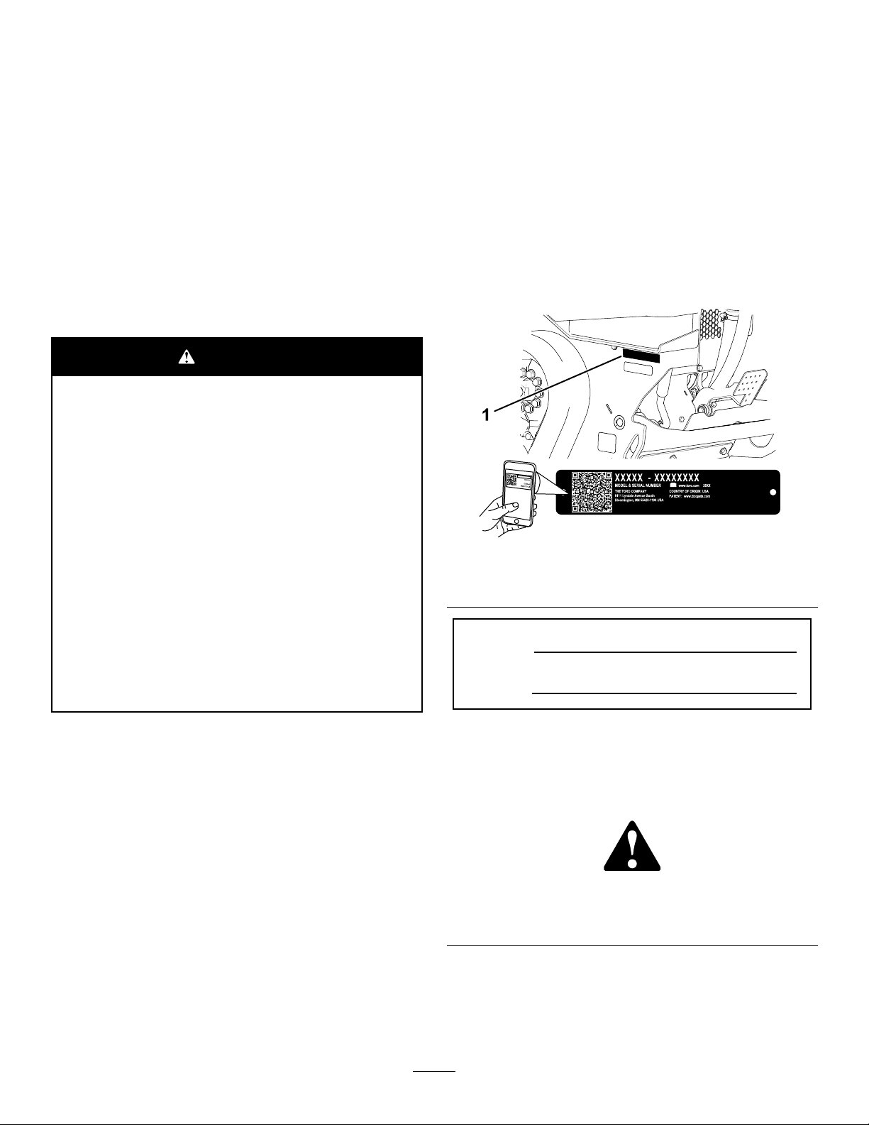
BatterySymbols
Someorallofthesesymbolsareonyourbattery.
1.Explosionhazard6.Keepbystandersaway
2.Nore,opename,or
smoking
3.Causticliquid/chemical
burnhazard
4.Weareyeprotection.9.Flusheyesimmediately
5.ReadtheOperator's
Manual.
fromthebattery.
7.Weareyeprotection;
explosivegasescan
causeblindnessandother
injuries.
8.Batteryacidcancause
blindnessorsevereburns.
withwaterandgetmedical
helpfast.
10.Containslead;donot
discard
decalbatterysymbols
decal93-9084
93-9084
1.Liftpoint
decal115-2047
115-2047
1.Warning—donottouchthehotsurface.
93-6680
93-6681
1.Cutting/dismembermenthazard,fan—stayawayfrom
movingparts.
93-7814
1.Entanglementhazard,belt—stayawayfrommovingparts;
keepallguardsandshieldsinplace.
decal115-4855
decal93-6680
115-4855
1.Hotsurface/burnhazard—wearprotectivegloveswhen
handlingthehydrauliccouplersandreadtheOperator's
Manualforinformationonhandlinghydrauliccomponents.
decal93-6681
decal115-4858
115-4858
1.Crushinghazardofhandsorfeet—installthecylinderlock.
decal93-7814
1.Enginecoolant
115-4865
2.ReadtheOperator's
Manual.
decal115-4865
5
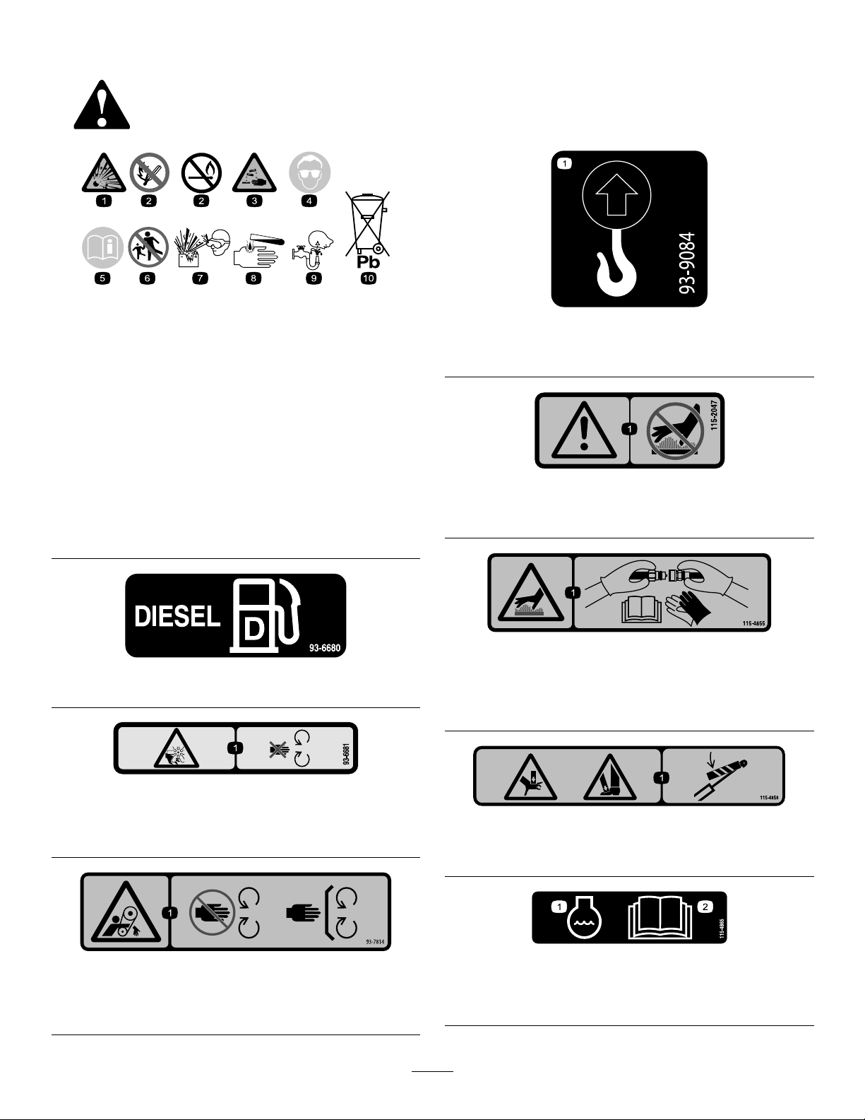
decal117-3276
117-3276
1.Enginecoolantunder
pressure
2.Explosionhazard—read
theOperator'sManual.
3.Warning—donottouchthe
hotsurface.
4.Warning—readthe
Operator'sManual.
120-0625
1.Pinchpoint,hand—keephandsaway.
decal125-6694
125–6694
1.Tiedownlocation
decal120-0625
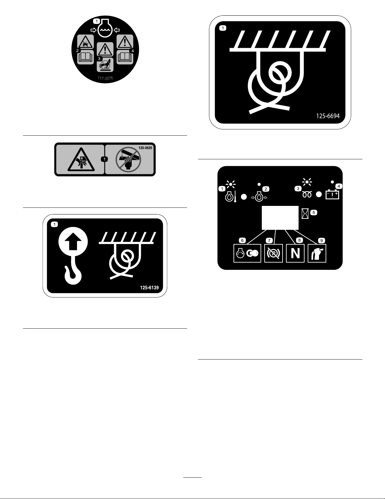
decal130-7637
130-7637
1.Liftpointandtie-downpoint
1.Blinking
decal125-6139
125-6139
light—engine-coolant
temperature
2.Steadylight—engine-oil
6.Enginestart
7.Parkingbrakedisengaged
pressure
3.Blinkinglight—glowplug8.Tractionneutral
4.Steadylight—battery
9.Auxiliaryleverneutral
warning
5.Hourmeter
6
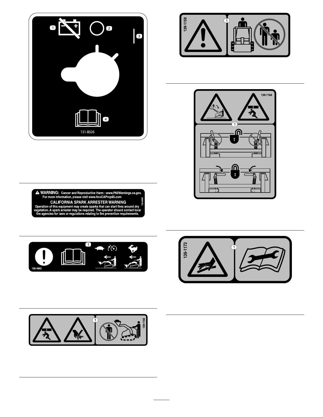
decal139-1159
139-1159
1.Warning—keepbystandersaway.
decal131-8026
131-8026
1.Battery
3.On
power—disconnect
2.Off4.ReadtheOperator's
Manual.
133-8062
136-4863
1.Attention—readtheOperator’sManual;SmartLoadwill
engageandslowthetractionspeedwhentheattachmentis
raised;lowertheattachmenttodrivequickly.
decal139-1164
139-1164
decal133-8062
decal136-4863
1.Crushinghazardfromabove,fallingload—ensurethatthe
quick-attachleversarelocked.
decal139-1173
139-1173
1.High-pressureuidhazard,injectionintothebody—read
theOperator’sManualbeforeperformingmaintenance.
139-1158
1.Crushinghazard,fromabove,andpinchinghazard—stay
awayfromthebucketandloadingarms.
decal139-1158
7
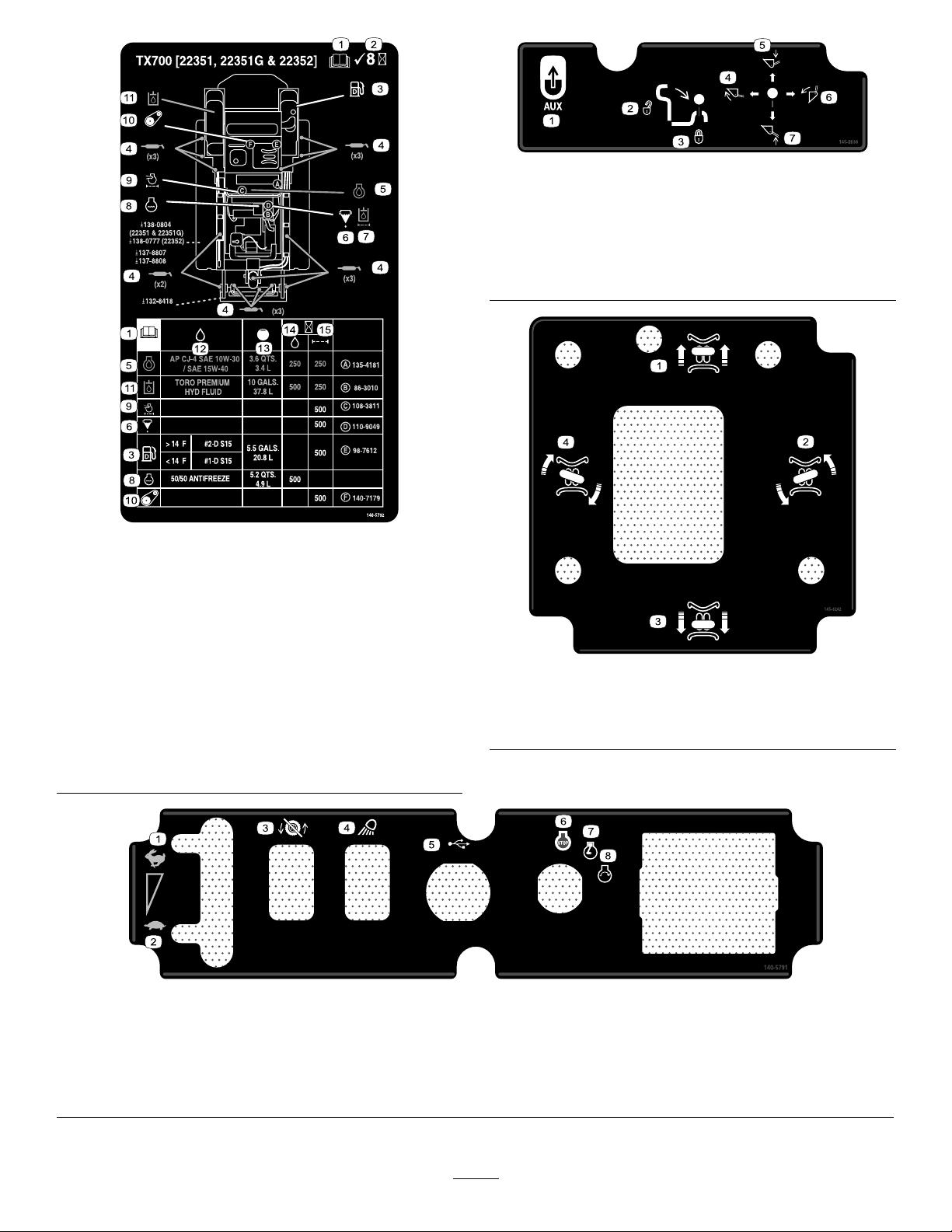
decal145-0638
145-0638
1.Auxiliary5.Lowertheattachment
2.Leverunlock6.Tilttheattachment
rearward
3.Leverlock7.Raisetheattachment
4.Tilttheattachmentforward
decal140-5792
140-5792
1.ReadtheOperator’s
9.Engineairlter
Manual.
2.Checkevery8hours
10.Belttension
3.Dieselfuel11.Hydraulicuid
4.Greasepoints12.Fluidspecication
5.Engineoil
6.Fuel/waterseparator
13.Capacity
14.Fluidchangeinterval
(hours)
7.Hydraulicuidlter
15.Filterchangeinterval
(hours)
8.Enginecoolant
decal145-3242
145-3242
1.Moveforward
2.Turnleft
3.Moverearward
4.Turnright
decal140-5791
140-5791
1.Fast
2.Slow
3.Tractiondisabled7.Engine—run
4.Worklight
5.USB
6.Engine—start
8.Engine—shutoff
8

decal145-0637
145-0637
1.Warning—readtheOperator'sManual.7.Cutting/severinghazardofhandorfoot—waitforallmoving
partstostopbeforeservicing;keepawayfrommovingparts;
keepallguardsandshieldsinplace.
2.Warning—receivetrainingbeforeoperatingthemachine.
8.Explosionhazard;electrocutionhazard—callthelocalutilities
hotlinebeforebeginningworkinanarea.
3.Warning—wearhearingprotection.
9.Crushinghazard—keepawayfromtheattachmentwhen
operatingthemachine;keepbystandersawayfromthe
machine.
4.Warning—engagetheparkingbrake,lowertheattachmentto
theground,shutofftheengine,andremovethekeyfromthe
ignitionbeforeleavingthemachine.
10.Tippinghazard—alwaysmoveupordownslopeswith
theattachmentlowered;neverdriveonaslopewiththe
attachmentraised;alwaysoperatewiththeheavyenduphill;
alwayscarryloadslow;neverjerkthecontrollevers;use
asteady,evenmotion.
5.Electrocutionhazard,powerlines—checkforpowerlinesin
theareabeforeusingthemachine.
11.Tippinghazard—donotmakefastturns;alwayscheckbehind
youbeforereversingthemachine.
6.Crushinghazard—keepawayfrompinchpoints;read
theOperator'sManualbeforeservicingorperforming
maintenance.
9
ProductOverview
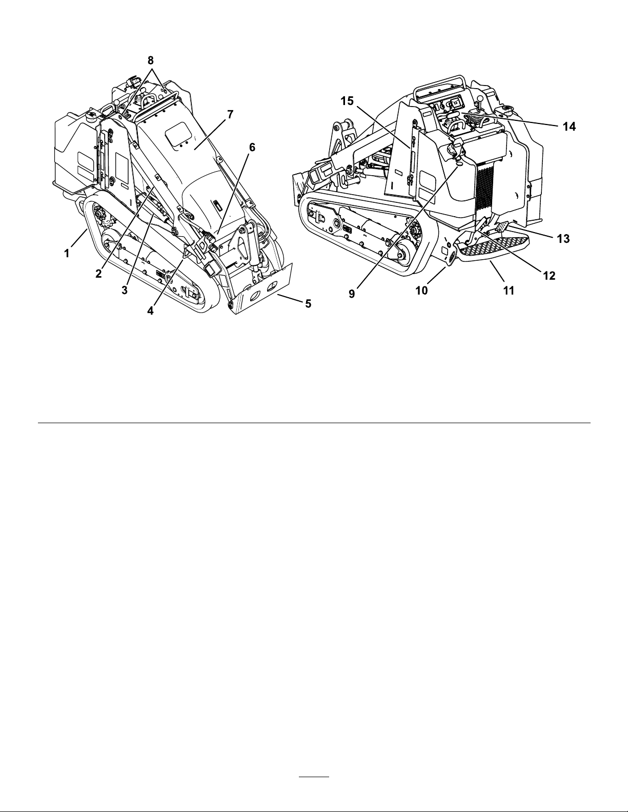
g318735
Figure3
1.Track6.Auxiliaryhydrauliccouplers
2.Loaderarm7.Hood12.Parkingbrake
3.Liftcylinder8.Liftpoint
4.Tie-down/liftloop
5.Mountplate10.Tie-downloop
9.Fuelgauge
11.Operatorplatform
13.Auxiliaryhydraulicslockpedal
14.Controlpanel
15.Cylinderlock
10
Controls
Traction-EnableSwitch
Becomefamiliarwithallthecontrolsbeforeyoustart
theengineandoperatethetractionunit.
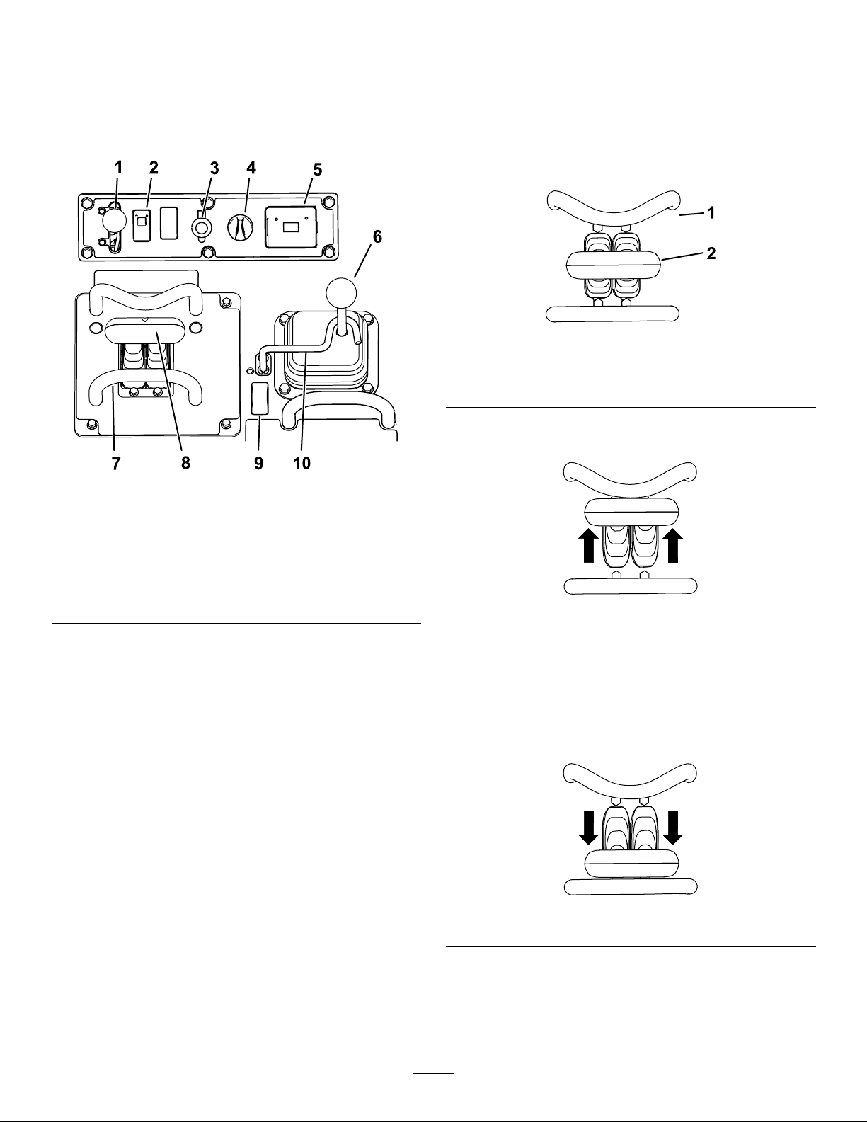
ControlPanel
Figure4
Thetractioncontrolisautomaticallydisabledwhen
startingthemachine.T ogglethetraction-enable
switchafterstartingthemachinetousethetraction
control.
TractionControl
g259646
Figure5
1.Referencebar
2.Tractioncontrol
•Tomoveforward,movethetractioncontrol
forward.
g318734
1.Throttlelever
2.Traction-enableswitch
3.Powersocket8.Tractioncontrol
4.Keyswitch9.Auxiliaryhydraulicsswitch
5.Hourmeter10.Loadervalvelock
6.Loader-arm/attachment-tilt
lever
7.Referencebar
KeySwitch
Thekeyswitch,usedtostartandshutofftheengine,
has3positions:OFF,RUN,andSTART.
ThrottleLever
Movethecontrolforwardtoincreasetheenginespeed
andrearwardtodecreasespeed.
ReferenceBar
Whendrivingthetractionunit,usethereferencebar
asahandleandaleveragepointforcontrollingthe
tractioncontrolandtheauxiliary-hydraulicslever.T o
ensuresmooth,controlledoperation,donottake
yourhandsoffthereferencebarswhileoperatingthe
machine.
g259645
Figure6
•Tomoverearward,movethetractioncontrol
rearward.
Important:Whenreversing,lookbehindyou
forobstructionsandkeepyourhandsonthe
referencebar.
g259647
Figure7
11

•Toturnright,rotatethetractioncontrolclockwise.
Figure8
•Toturnleft,rotatethetractioncontrol
counterclockwise.
Figure9
•Tostopthemachine,releasethetractioncontrol.
Note:Thefartheryoumovethetractioncontrolin
anydirection,thefasterthemachinemovesinthat
direction.
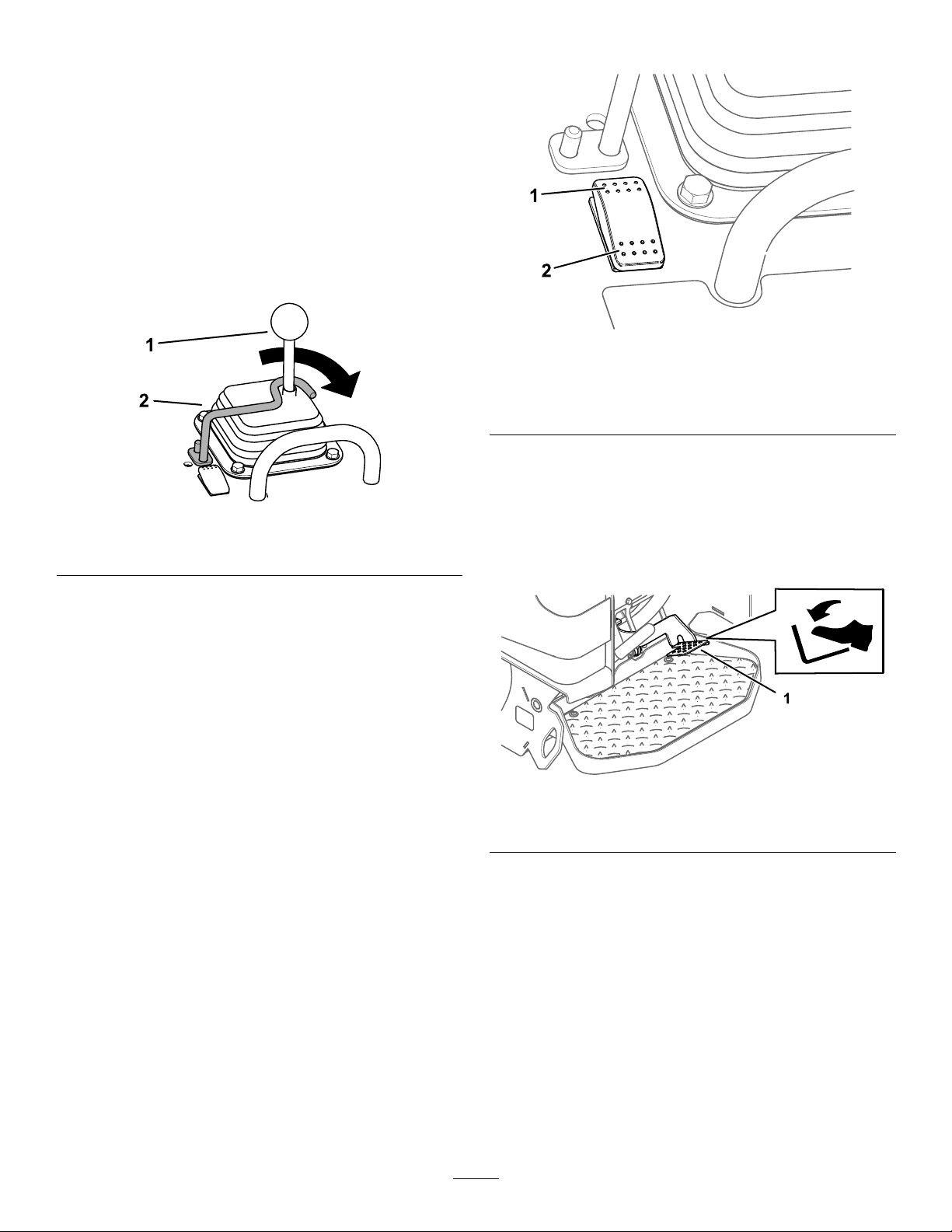
LoaderArm/Attachment-TiltLever
Slowlymovethelevertooperatetheloaderarmsand
tilttheattachment.
Note:Thedetent(oat)positionallowsattachments
suchasthelevelerandthehydraulicbladetofollow
thecontoursoftheground(i.e.,oat)whengrading.
g259649
g356466
Figure10
g259648
1.Detent(oat)
position—pushthelever
fullyforward.
2.Lowertheloaderarms.5.Tilttheattachment
3.Raisetheloaderarms.
Bymovingthelevertoanintermediateposition(e.g.,
forwardandleft),youcanmovetheloaderarmsand
tilttheattachmentatthesametime.
4.Tilttheattachment
rearward.
forward.
12
Loader-ValveLock
Theloader-valvelocksecurestheloader
arm/attachment-tiltleversothatyoucannotpushit
forward.Thishelpstoensurethatnooneaccidentally
lowerstheloaderarmsduringmaintenance.Secure
theloadervalvewiththelock,inadditiontothe
cylinderlocks,anytimeyouneedtoshutoffthe
machinewiththeloaderarmsraised.RefertoUsing
theCylinderLocks(page28).
Tosetthelock,liftitsothatitclearstheholeinthe
controlpanelandswinginfrontoftheloader-arm
lever.Pushitdownintothelockedposition.
Auxiliary-HydraulicsControls
g357085
Figure12
Figure11
1.Loader-valvelock
Loader-Control-ReferenceBar
Theloader-control-referencebarhelpsstabilizeyour
handwhileoperatingtheloaderarm/attachment-tilt
lever(Figure4).
1.Operateauxiliary
hydraulicsintheforward
direction.
2.Operateauxiliary
hydraulicsinthereverse
direction.
Auxiliary-HydraulicsLockPedal
g357087
Useyourrightfoottopresstheauxiliary-hydraulics
lockpedaltocontinuetheforwardorreverseowof
theauxiliaryhydraulicsandfreeyourhandforother
controls.
g357086
Figure13
1.Auxiliary-hydraulicslockpedal
13
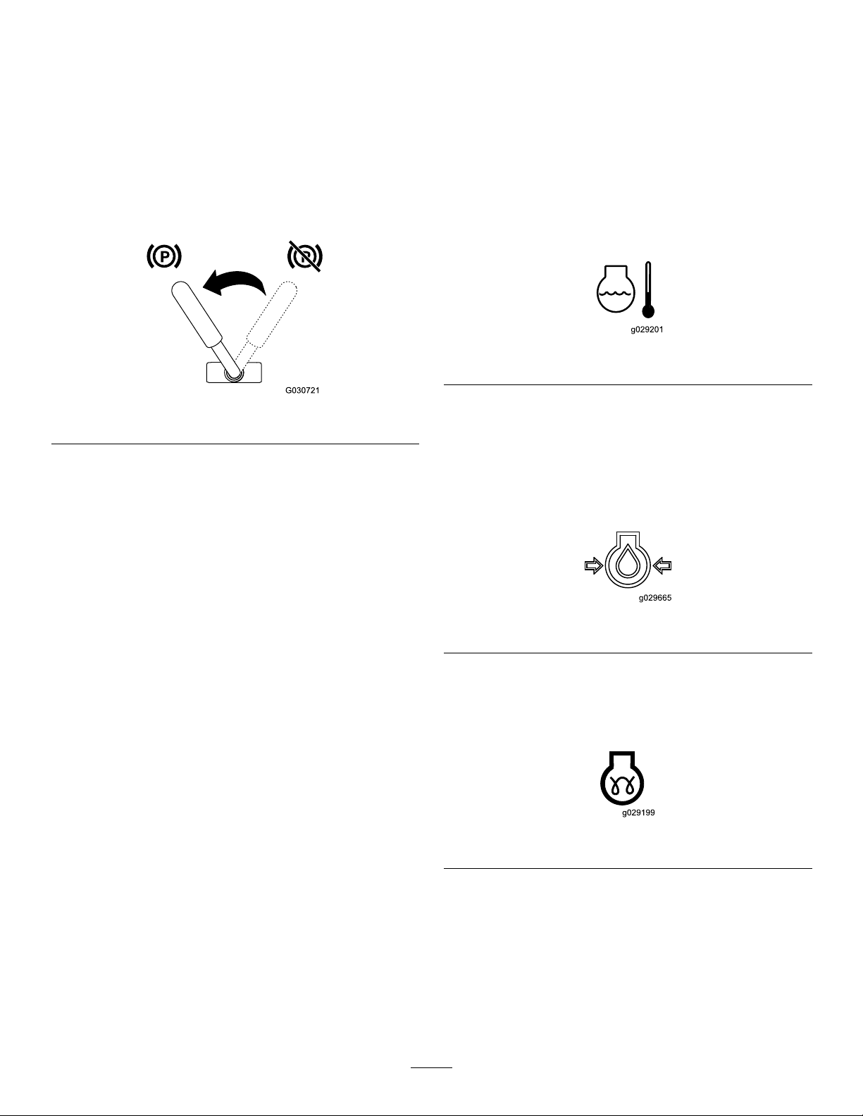
Parking-BrakeLever
MessageDisplay
•Toengagetheparkingbrake,rotatetheleverto
left.
Note:Thetractionunitmayrollslightlybeforethe
brakesengageinthedrivesprocket.
•Toreleasethebrake,rotatethebrakelevertothe
right.
Note:Y oumayneedtoadjustthetractioncontrol
toreleasethebrakepinsandrotatethelever.
Figure14
FuelGauge
Thisgaugemeasurestheamountoffuelinthefuel
tank(s).
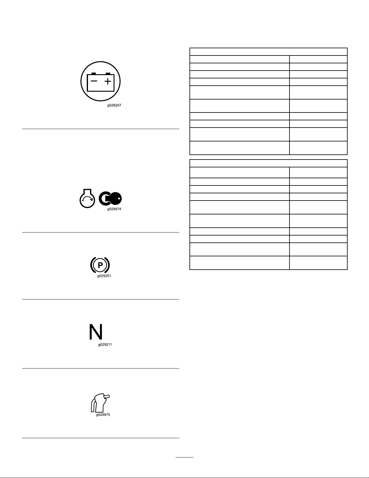
Engine-Coolant-TemperatureLight
Iftheenginecoolantbecomestoohot,thelighton
theleftofthedisplayashesandthehornsounds.If
thishappens,disengagetheauxiliaryhydraulicsand
letthemachinerunathighidletoallowthecooling
systemtocoolthemachine.Checkthecoolantlevel
whentheenginehasfullycooled.
Important:Donotshutofftheengine,asthis
maycausethemachinetooverheat.
g029201
Figure15
g030721
Engine-Oil-PressureLight
Iftheengine-oil-pressurebecomestoolow,thelight
ontheleftofthedisplayilluminatessteadily.Ifthis
happens,shutofftheengineimmediatelyandcheck
theoillevel.Ifitislow,addoilandlookforpossible
leaks.
Figure16
Glow-PlugLight
Thelightontherightasheswhiletheglowplugsare
chargedandwarmingtheengine.
Figure17
g029665
g029199
14
Battery-ChargeLight
Ifthebatterychargebecomestoolow,thelighton
therightilluminatessteadily.Ifthishappens,shutoff
theengineandchargeorreplacethebattery .Refer
toServicingtheBattery(page37).
Figure18
HourMeter
Thehourmeterdisplaysthenumberofhoursof
operationthathavebeenloggedonthetractionunit
andthefollowingindicators:
•Enginestart—displayswhenyoustarttheengine
Figure19
•Parkingbrake—displayswhenyoudisengagethe
parkingbrake
Specications
Note:Specicationsanddesignaresubjectto
changewithoutnotice.
Model22351and22351G
Width
Length
Height
Weight
Operatingcapacity(with75kg(165lb)
operatorandstandardbucket)
Tippingcapacity(with75kg(165lb)
g029207
g029974
operatorandstandardbucket)
Wheelbase
Dumpheight(withstandardbucket)133.4cm(52.5inches)
Reach—fullyraised(withstandard
bucket)
Heighttohingepin(withstandard
bucketinhighestposition)
Model22352
Width
Length
Height
Weight
Operatingcapacity(with75kg(165lb)
operatorandstandardbucket)
Tippingcapacity(with75kg(165lb)
operatorandstandardbucket)
Wheelbase
Dumpheight(withstandardbucket)133.4cm(52.5inches)
Reach—fullyraised(withstandard
bucket)
Heighttohingepin(withstandard
bucketinhighestposition)
86.9cm(34.2inches)
202.7cm(79.8inches)
140.5cm(55.3inches)
1250kg(2756lb)
318kg(700lb)
907kg(2000lb)
99.1cm(39.0inches)
78.2cm(30.8inches)
187.2cm(73.7inches)
102.1cm(40.2inches)
202.7cm(79.8inches)
140.5cm(55.3inches)
1298kg(2862lb)
318kg(700lb)
918kg(2023lb)
99.1cm(39.0inches)
78.2cm(30.8inches))
187.2cm(73.7inches)
Figure20
•Tractionneutral—displayswhenthetraction
controlisintheNEUTRALposition
Figure21
•Auxiliaryleverneutral—displayswhentheauxiliary
leverisintheNEUTRALposition
Figure22
g029251
g029211
g029975
Attachments/Accessories
AselectionofT oroapprovedattachmentsand
accessoriesisavailableforusewiththemachine
toenhanceandexpanditscapabilities.Contact
yourAuthorizedServiceDealerorauthorizedToro
distributororgotowww.T oro.comforalistofall
approvedattachmentsandaccessories.
Toensureoptimumperformanceandcontinuedsafety
certicationofthemachine,useonlygenuineT oro
replacementpartsandaccessories.Replacement
partsandaccessoriesmadebyothermanufacturers
couldbedangerous,andsuchusecouldvoidthe
productwarranty .
15

Operation
Note:Determinetheleftandrightsidesofthe
machinefromthenormaloperatingposition.
FuelSafety
•Useextremecarewhenhandlingfuel.Itis
ammableanditsvaporsareexplosive.
•Extinguishallcigarettes,cigars,pipes,andother
sourcesofignition.
BeforeOperation
BeforeOperationSafety
GeneralSafety
•Neverallowchildrenoruntrainedpeopleto
operateorservicethemachine.Localregulations
mayrestricttheageorrequirecertiedtrainingof
theoperator.Theownerisresponsiblefortraining
alloperatorsandmechanics.
•Becomefamiliarwiththesafeoperationofthe
equipment,operatorcontrols,andsafetydecals.
•Alwaysengagetheparkingbrake(ifequipped),
shutofftheengine,removethekey,waitforall
movingpartstostop,andallowthemachine
tocoolbeforeadjusting,servicing,cleaning,or
storingthemachine.
•Knowhowtostopthemachineandshutoffthe
enginequickly .
•Checkthattheoperator'spresencecontrols,safety
switches,andshieldsareattachedandfunctioning
properly.Donotoperatethemachineunlessthey
arefunctioningproperly.
•Useonlyanapprovedfuelcontainer.
•Donotremovethefuelcaporllthefueltank
whiletheengineisrunningorhot.
•Donotaddordrainfuelinanenclosedspace.
•Donotstorethemachineorfuelcontainerwhere
thereisanopename,spark,orpilotlight,such
asonawaterheaterorotherappliance.
•Ifyouspillfuel,donotattempttostarttheengine;
avoidcreatinganysourceofignitionuntilthefuel
vaporshavedissipated.
•Topreventastaticchargefromignitingthefuel,
removethemachinefromthetruckortrailerand
refuelitontheground,awayfromallvehicles.If
thisisnotpossible,placeaportablefuelcontainer
ontheground,awayfromallvehicles,andllit;
thenrefuelthemachinefromthefuelcontainer
ratherthanfromafuel-dispensernozzle.
•Keepthefuel-dispensernozzleincontactwith
therimofthefueltankorcontaineropeningat
alltimesuntilfuelingiscomplete.Donotusea
nozzlelock-opendevice.
AddingFuel
•Locatethepinch-pointareasmarkedonthe
machineandattachments;keepyourhandsand
feetawayfromtheseareas.
•Beforeoperatingthemachinewithanattachment,
ensurethattheattachmentisproperlyinstalled
andthatitisagenuineT oroattachment.Readall
theattachmentmanuals.
•Evaluatetheterraintodeterminewhataccessories
andattachmentsyouneedtoproperlyandsafely
performthejob.
•Havethepropertyorworkareamarkedforburied
linesandotherobjects,anddonotdiginmarked
areas;notethelocationofunmarkedobjectsand
structures,suchasundergroundstoragetanks,
wells,andsepticsystems.
•Inspecttheareawhereyouwillusetheequipment
andremovealldebris.
•Ensurethattheareaisclearofbystandersbefore
operatingthemachine.Stopthemachineif
anyoneentersthearea.
RecommendedFuel
Useonlyclean,freshdieselfuelorbiodieselfuelswith
low(<500ppm)orultralow(<15ppm)sulfurcontent.
Theminimumcetaneratingshouldbe40.Purchase
fuelinquantitiesthatyoucanusewithin180daysto
ensurefuelfreshness.
Usesummer-gradedieselfuel(No.2-D)at
temperaturesabove-7°C(20°F)andwintergrade
(No.1-DorNo.1-D/2-Dblend)belowthat
temperature.Usingwinter-gradefuelatlower
temperaturesprovideslowerashpointandcoldow
characteristics,whicheasesstartingandreducesfuel
lterplugging.
Usingsummer-gradefuelabove-7°C(20°F)
contributestowardlongerfuelpumplifeandincreased
powercomparedtowinter-gradefuel.
Important:Donotusekeroseneorgasoline
insteadofdieselfuel.Failuretoobservethis
cautionwilldamagetheengine.
16
BiodieselReady
FillingtheFuelTank
Thismachinecanalsouseabiodieselblendedfuel
ofuptoB20(20%biodiesel,80%petrodiesel).The
petrodieselportionshouldbeloworultralowsulfur.
Observethefollowingprecautions:
•Thebiodieselportionofthefuelmustmeet
specicationASTMD6751orEN14214.
•TheblendedfuelcompositionshouldmeetASTM
D975orEN590.
•Paintedsurfacesmaybedamagedbybiodiesel
blends.
•UseB5(biodieselcontentof5%)orlesserblends
incoldweather.
•Monitorseals,hoses,gasketsincontactwithfuel
astheymaydegradeovertime.
•Fuellterpluggingmayoccurforatimeafter
convertingtobiodieselblends.
•Contactyourdistributorformoreinformationon
biodiesel.
Fueltankcapacity:20.8L(5.5USgallons)
1.Parkthemachineonalevelsurface,engagethe
parkingbrake,andlowertheloaderarms.
2.Shutofftheengineandremovethekey.
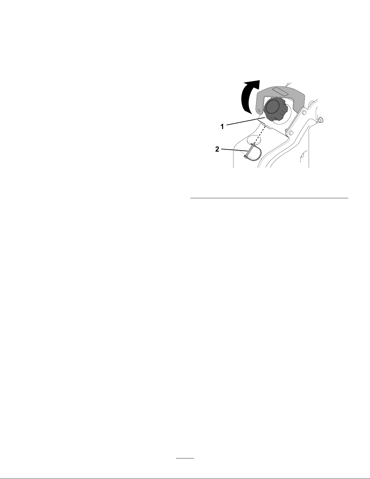
3.Removethesnapperpinandraisethebracket.
Figure23
1.Fuelcap
2.Snapperpin
g367241
4.Removethefuelcap.
5.Fillthetankwithfueluptothellerneck.
6.Installthecap.
7.Lowerthebracketandsecureitwiththesnapper
pin.
PerformingDaily
Maintenance
Beforestartingthemachineeachday,performthe
EachUse/DailyprocedureslistedinMaintenance
(page26).
Important:Checkthehydraulic-uidlevel
andbleedthefuelsystembeforestartingthe
engineforthersttime;refertoCheckingthe
Hydraulic-FluidLevel(page48)andBleedingthe
FuelSystem(page36).
17

DuringOperation
DuringOperationSafety
GeneralSafety
•Donotexceedtheratedoperatingcapacity ,asthe
machinemaybecomeunstable,whichmayresult
inlossofcontrol.
•Donotcarryaloadwiththearmsraised.Always
carryloadsclosetotheground.
•UseonlyT oro-approvedattachmentsand
accessories.Attachmentscanchangethestability
andtheoperatingcharacteristicsofthemachine.
•Formachineswithaplatform:
–Lowertheloaderarmsbeforesteppingoffthe
platform.
–Donottrytostabilizethemachinebyputting
yourfootontheground.Ifyoulosecontrolof
themachine,stepofftheplatformandaway
fromthemachine.
–Donotplaceyourfeetundertheplatform.
–Donotmovethemachineunlessyouare
standingwithbothfeetontheplatformandyour
handsareholdingontothereferencebars.
•Useyourfullattentionwhileoperatingthe
machine.Donotengageinanyactivitythat
causesdistractions;otherwise,injuryorproperty
damagemayoccur.
•Lookbehindanddownbeforebackingupto
ensurethatthepathisclear.
•Neverjerkthecontrols;useasteadymotion.
•Theowner/usercanpreventandisresponsible
foraccidentsthatmaycausepersonalinjuryor
propertydamage.
•Wearappropriateclothingincludinggloves,eye
protection,longpants,substantialslip-resistant
footwear,andhearingprotection.Tiebacklong
hairanddonotwearlooseclothingorloose
jewelry.
•Donotoperatethemachinewhenyouaretired,ill,
orundertheinuenceofalcoholordrugs.
•Nevercarrypassengersandkeeppetsand
bystandersawayfromthemachine.
•Operatethemachineonlyingoodlight,keeping
awayfromholesandhiddenhazards.
•Ensurethatallthedrivesareinneutralandengage
theparkingbrake(ifequipped)beforestartingthe
engine.Starttheengineonlyfromtheoperator's
position.
•Usecarewhenapproachingblindcorners,shrubs,
trees,orotherobjectsthatmayobscurevision.
•Slowdownandusecautionwhenmakingturns
andcrossingroadsandsidewalks.Watchfor
trafc.
•Stoptheattachmentwhenyouarenotworking.
•Stopthemachine,shutofftheengine,remove
thekey,andinspectthemachineifyoustrike
anobject.Makeanynecessaryrepairsbefore
resumingoperation.
•Neverrunanengineinanenclosedarea.
•Neverleavearunningmachineunattended.
•Beforeleavingtheoperatingposition,dothe
following:
–Parkthemachineonalevelsurface.
–Lowertheloaderarmsanddisengagethe
auxiliaryhydraulics.
–Engagetheparkingbrake(ifequipped).
–Shutofftheengineandremovethekey.
•Donotoperatethemachinewhenthereistherisk
oflightning.
•Operatethemachineonlyinareaswherethereis
sufcientclearanceforyoutosafelymaneuver.
Beawareofobstaclesincloseproximitytoyou.
Failuretomaintainadequatedistancefromtrees,
walls,andotherbarriersmayresultininjuryasthe
machinebacksupduringoperationifyouarenot
attentivetothesurroundings.
•Checkforoverheadclearance(i.e.,electrical
wires,branches,anddoorways)beforedriving
underanyobjectsanddonotcontactthem.
•Donotoverlltheattachmentandalwayskeepthe
loadlevelwhenraisingtheloaderarms.Itemsin
theattachmentcouldfallandcauseinjury .
SlopeSafety
•Operatethemachineupanddownslopeswith
theheavyendofthemachineuphill.Weight
distributionchangeswithattachments.Anempty
bucketmakestherearofthemachinetheheavy
end,andafullbucketmakesthefrontofthe
machinetheheavyend.Mostotherattachments
makethefrontofmachinetheheavyend.
•Raisingtheloaderarmsonaslopeaffectsthe
stabilityofthemachine.Keeptheloaderarmsin
theloweredpositionwhenonslopes.
•Slopesareamajorfactorrelatedtolossofcontrol
andtip-overaccidents,whichcanresultinsevere
injuryordeath.Operatingthemachineonany
slopeoruneventerrainrequiresextracaution.
•Establishyourownproceduresandrulesfor
operatingonslopes.Theseproceduresmust
includesurveyingthesitetodeterminewhich
slopesaresafeformachineoperation.Always
18

usecommonsenseandgoodjudgmentwhen
performingthissurvey.
–Donotallowanotherindividualtotouchor
approachthemachinewhencharged.
•Slowdownanduseextracareonhillsides.Ground
conditionscanaffectthestabilityofthemachine.
•Avoidstartingorstoppingonaslope.Ifthe
machinelosestraction,proceedslowly ,straight
downtheslope.
•Avoidturningonslopes.Ifyoumustturn,turn
slowlyandkeeptheheavyendofthemachine
uphill.
•Keepallmovementsonslopesslowandgradual.
Donotmakesuddenchangesinspeedor
direction.
•Ifyoufeeluneasyoperatingthemachineona
slope,donotdoit.
•Watchforholes,ruts,orbumps,asuneventerrain
couldoverturnthemachine.T allgrasscanhide
obstacles.
•Usecautionwhenoperatingonwetsurfaces.
Reducedtractioncouldcausesliding.
•Evaluatetheareatoensurethatthegroundis
stableenoughtosupportthemachine.
•Usecautionwhenoperatingthemachinenearthe
following:
–Drop-offs
–Ditches
–Embankments
–Bodiesofwater
Themachinecouldsuddenlyrolloverifatrack
goesovertheedgeortheedgecavesin.Maintain
asafedistancebetweenthemachineandany
hazard.
–Alwaysassumethemachineischargedifyou
strikeanelectricalorcommunicationline.Do
notattempttoleavethemachine.
•Leakinggasisbothammableandexplosiveand
maycauseseriousinjuryordeath.Donotsmoke
whileoperatingthemachine.
StartingtheEngine
1.Ensurethatthebattery-disconnectswitchisin
theONposition.
2.Ensurethatthetraction-controlisintheNEUTRAL
position.
3.MovethethrottlelevertotheSLOWposition.
4.Insertthekeyintothekeyswitchandturnitto
theONposition.
5.Waitfortheglow-plugindicatorlighttostop
blinking.
6.TurnthekeytotheST ARTposition.Whenthe
enginestarts,releasethekey.
Important:Donotengagethestarterfor
morethan10secondsatatime.Iftheengine
failstostart,wait30secondsforthestarter
tocooldownbetweenattempts.Failureto
followtheseinstructionscouldburnoutthe
startermotor.
7.MovethethrottlelevertotheFASTposition.
8.Enablethetractioncontrolbytogglingthe
traction-enableswitchbeforedrivingthe
machine.
•Donotremoveoraddattachmentsonaslope.
•Donotparkthemachineonahillsideorslope.
UtilityLineSafety
•Ifyoustrikeautilityline,dothefollowing:
–Shutoffthemachineandremovethekey.
–Removeallindividualsfromtheworkarea.
–Immediatelycontacttheproperemergencyand
utilityauthoritiestosecurethearea.
–Ifyoudamageaber-opticcable,donotlook
intotheexposedlight.
•Donotleavetheoperator’splatformifthemachine
ischargedwithelectricity.Youwillbesafeaslong
asyoudonotleavetheplatform.
–Touchinganypartofthemachinemayground
you.
StartinginColdWeather
Iftheoutdoortemperatureisbelowfreezing,store
thetractionunitinagaragetokeepitwarmerandto
aidinstarting.
Whenstartingtheengineincoldconditions(i.e.,when
theairtemperatureisatorbelowfreezing),allowitto
runintheSLOWthrottlepositionfor8minutesbefore
movingthethrottletotheFASTpositionorengaging
theauxiliaryhydraulics.
Important:Runningtheengineathighspeeds
whenthehydraulicsystemiscoldcoulddamage
thehydraulicsystem.
19
DrivingtheMachine
Note:Enablethetractioncontrolbytogglingthe
traction-enableswitchbeforedrivingthemachine.
Usethetractioncontroltomovethemachine.The
fartheryoumovethetractioncontrolinanydirection,
thefasterthemachinemovesinthatdirection.
Releasethetractioncontroltostopthemachine.
Thethrottlecontrolregulatestheenginespeedas
measuredinrpm(revolutionsperminute).Placethe
throttleleverintheFASTpositionforbestperformance.
Youcan,however,usethethrottlepositiontooperate
atslowerspeeds.
ShuttingOfftheEngine
1.Parkthemachineonalevelsurface,engage
theparkingbrake(ifequipped),andlowerthe
loaderarms.
2.Ensurethattheauxiliaryhydraulicsleverisin
theNEUTRALposition.
3.MovethethrottlelevertotheSLOWposition.
4.Iftheenginehasbeenworkinghardorishot,let
itidleforaminutebeforeturningthekeyswitch
totheOFFposition.
Note:Thishelpstocooltheenginebeforeyou
shutitoff.Inanemergency ,youcanshutoff
theengineimmediately.
5.TurnthekeyswitchtotheOFFpositionand
removethekey.
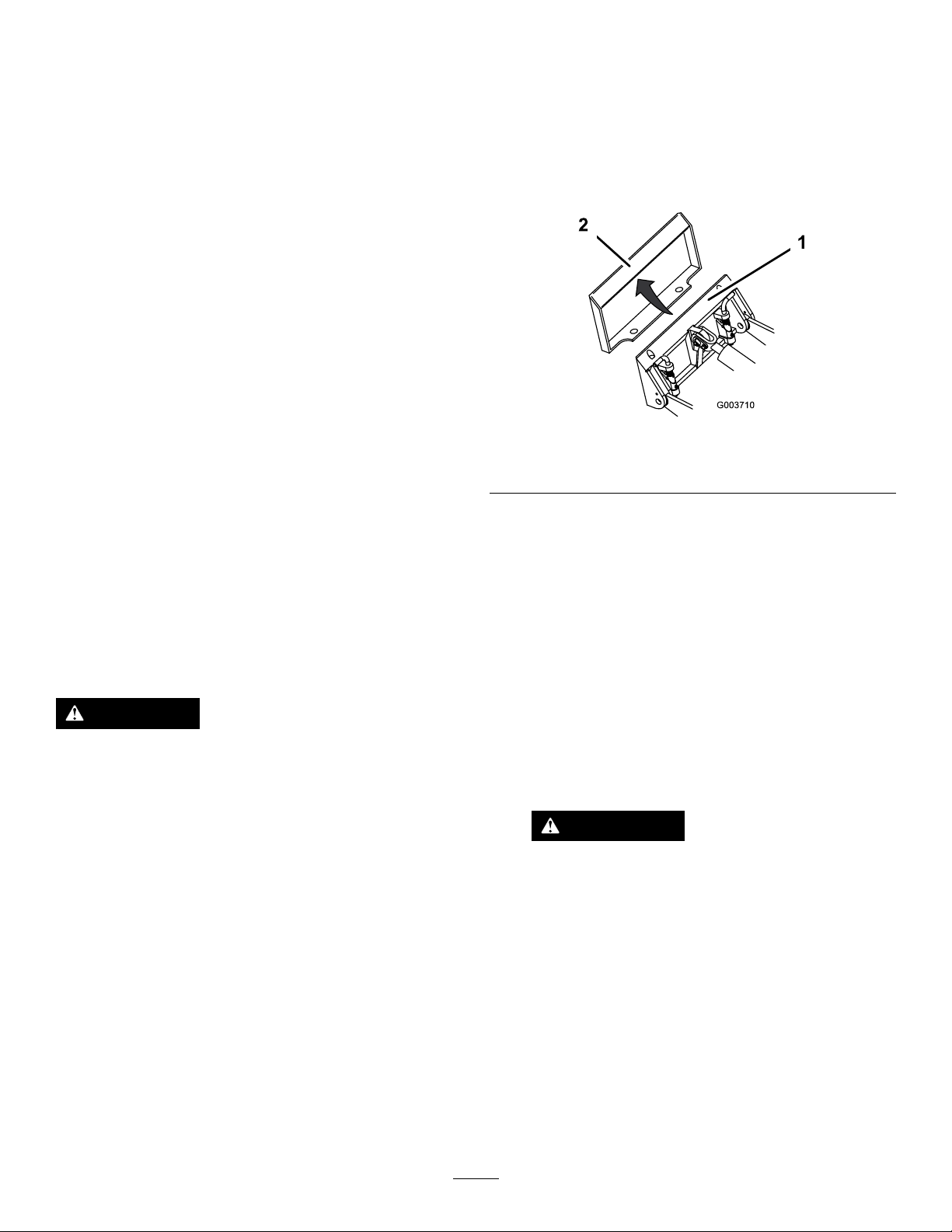
1.Positiontheattachmentonalevelsurfacewith
enoughspacebehindittoaccommodatethe
machine.
2.Starttheengine.
3.Tilttheattachmentmountplateforward.
4.Positionthemountplateintotheupperlipofthe
attachmentreceiverplate.
g003710
Figure24
1.Mountplate2.Receiverplate
5.Raisetheloaderarmswhiletiltingbackthe
mountplateatthesametime.
Important:Raisetheattachmentenoughto
clearthegroundandtiltthemountplateall
thewayback.
6.Shutofftheengineandremovethekey.
7.Engagethequick-attachpins,ensuringthatthey
arefullyseatedinthemountplate.
CAUTION
Achildoruntrainedbystandercouldattempt
tooperatethetractionunitandbeinjured.
Removethekeyfromthekeyswitchwhen
leavingthetractionunit,evenifjustforafew
seconds.
UsingAttachments
InstallinganAttachment
Important:UseonlyT oro-approvedattachments.
Attachmentscanchangethestabilityandthe
operatingcharacteristicsofthemachine.The
warrantyofthemachinemaybevoidedifyouuse
themachinewithunapprovedattachments.
Important:Beforeinstallingtheattachment,
ensurethatthemountplatesarefreeofanydirtor
debrisandthatthepinsrotatefreely .Ifthepins
donotrotatefreely,greasethem.
Important:Ifthepinsdonotrotatetothe
engagedposition,themountplateisnot
fullyalignedwiththeholesintheattachment
receiverplate.Checkthereceiverplateand
cleanitifnecessary.
WARNING
Ifyoudonotfullyseatthequick-attach
pinsthroughtheattachmentmountplate,
theattachmentcouldfalloffthemachine,
crushingyouorbystanders.
Ensurethatthequick-attachpinsarefully
seatedintheattachmentmountplate.
20
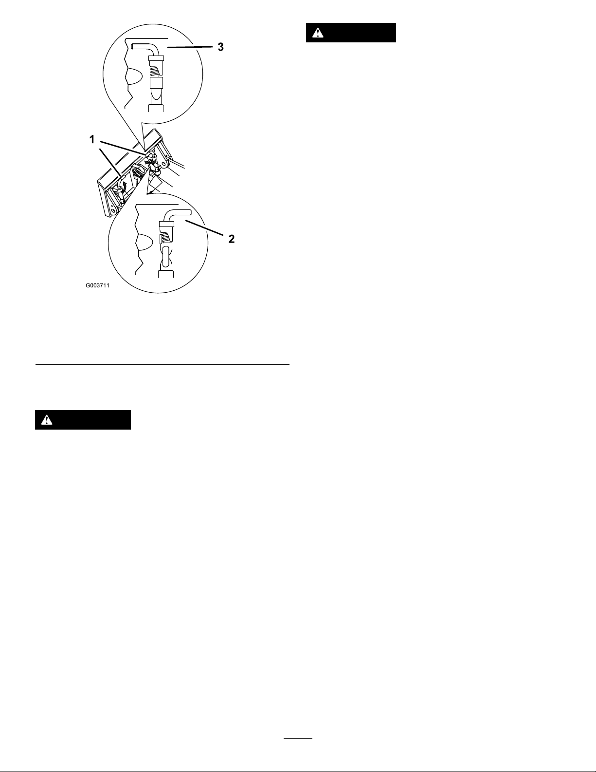
Figure25
1.Quick-attachpins
(engagedposition)
2.Disengagedposition
3.Engagedposition
ConnectingtheHydraulicHoses
WARNING
g003711
CAUTION
Hydrauliccouplers,hydrauliclines/valves,
andhydraulicuidmaybehot.Ifyoucontact
hotcomponents,youmaybeburned.
•Weargloveswhenoperatingthehydraulic
couplers.
•Allowthemachinetocoolbeforetouching
hydrauliccomponents.
•Donottouchhydraulicuidspills.
Iftheattachmentrequireshydraulicsforoperation,
connectthehydraulichosesasfollows:
1.Shutofftheengineandremovethekey.
2.Movetheauxiliary-hydraulicsleverforward,
backward,andbacktotheNEUTRALpositionto
relievepressureatthehydrauliccouplers.
3.Removetheprotectivecoversfromthehydraulic
connectorsonthemachine.
4.Ensurethatallforeignmatteriscleanedfrom
thehydraulicconnectors.
5.Pushtheattachmentmaleconnectorintothe
femaleconnectoronthemachine.
Note:Whenyouconnecttheattachmentmale
connectorrst,yourelieveanypressurebuilt
upintheattachment.
6.Pushtheattachmentfemaleconnectorontothe
maleconnectoronthemachine.
7.Conrmthattheconnectionissecurebypulling
onthehoses.
Hydraulicuidescapingunderpressurecan
penetrateskinandcauseinjury.Fluidinjected
intotheskinmustbesurgicallyremoved
withinafewhoursbyadoctorfamiliarwith
thisformofinjury;otherwise,gangrenemay
result.
•Ensurethatallhydraulic-uidhoses
andlinesareingoodconditionandall
hydraulicconnectionsandttingsaretight
beforeapplyingpressuretothehydraulic
system.
•Keepyourbodyandhandsawayfrom
pinholeleaksornozzlesthateject
high-pressurehydraulicuid.
•Usecardboardorpapertondhydraulic
leaks;neveruseyourhands.
RemovinganAttachment
1.Parkthemachineonalevelsurface.
2.Lowertheattachmenttotheground.
3.Shutofftheengineandremovethekey.
4.Disengagethequick-attachpinsbyturningthem
totheoutside.
5.Iftheattachmentuseshydraulics,movethe
auxiliary-hydraulicsleverforward,backward,
andbacktotheNEUTRALpositiontorelieve
pressureatthehydrauliccouplers.
6.Iftheattachmentuseshydraulics,slidethe
collarsbackonthehydrauliccouplersand
disconnectthem.
Important:Connecttheattachmenthoses
togethertopreventhydraulicsystem
contaminationduringstorage.
7.Installtheprotectivecoversontothehydraulic
couplersonthemachine.
8.Starttheengine,tiltthemountplateforward,and
backthemachineawayfromtheattachment.
21

AfterOperation
MovingaNon-Functioning
Machine
AfterOperationSafety
GeneralSafety
•Engagetheparkingbrake(ifequipped),lower
theloaderarms,shutofftheengine,removethe
key,waitforallmovementtostop,andallowthe
machinetocoolbeforeadjusting,cleaning,storing,
orservicingit.
•Cleandebrisfromtheattachments,drives,
mufers,andenginetohelppreventres.Clean
upoilorfuelspills.
•Keepallpartsingoodworkingconditionandall
hardwaretightened.
•Donottouchpartsthatmaybehotfromoperation.
Allowthemtocoolbeforeattemptingtomaintain,
adjust,orservicethemachine.
•Usecarewhenloadingorunloadingthemachine
intoatrailerortruck.
RetrievingaStuckMachine
Important:Donottoworpullthemachine
withoutrstopeningthetowvalves,oryouwill
damagethehydraulicsystem.
1.Shutofftheengineandremovethekey.
2.Openthehoodandsecurethehoodprop.
3.Usingawrench,turnthetowvalvesonthe
hydraulicpumpstwicecounterclockwise.
g357135
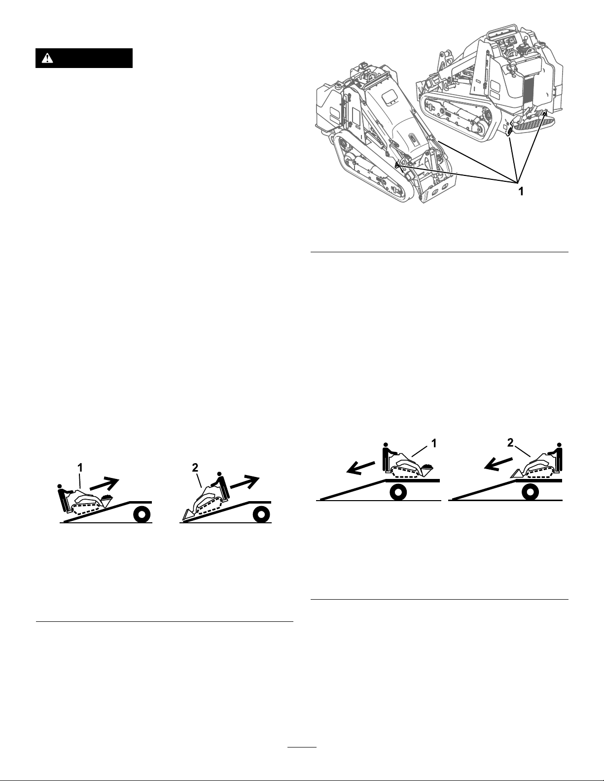
Ifthemachinebecomesstuck(e.g.,inmuddy
conditions),pullthemachinebackintoastable
positionusingeitherbothfronttie-down/liftpointsor
bothreartie-downpointssimultaneously .
Figure26
1.Fronttie-down/liftpoints
2.Reartie-downpoints
g365261
Figure27
1.T owvalve
4.Towthemachineasrequired.
5.Afterrepairingthemachine,closethetowvalves
beforeoperatingit.
g377832
22

HaulingtheMachine
Useaheavy-dutytrailerortrucktohaulthemachine.
Useafull-widthramp.Ensurethatthetrailerortruck
hasallthenecessarybrakes,lighting,andmarkingas
requiredbylaw.Pleasecarefullyreadallthesafety
instructions.Knowingthisinformationcouldhelp
youorbystandersavoidinjury .Refertoyourlocal
ordinancesfortrailerandtie-downrequirements.
WARNING
Drivingonthestreetorroadwaywithout
turnsignals,lights,reectivemarkings,ora
slow-moving-vehicleemblemisdangerous
andcanleadtoaccidentscausingpersonal
injury.
Donotdrivethemachineonapublicstreet
orroadway.
SelectingaTrailer
WARNING
Loadingamachineontoatrailerortruck
increasesthepossibilityoftip-overandcould
causeseriousinjuryordeath(Figure28).
•Useonlyfull-widthramps.
•Ensurethatthelengthoframpisatleast4
timesaslongastheheightofthetraileror
truckbedtotheground.Thisensuresthat
rampangledoesnotexceed15degreeson
atground.
1.Full-widthramp(s)in
stowedposition
2.Rampisatleast4times
aslongastheheightof
thetrailerortruckbedto
theground
g229507
Figure28
3.H=heightofthetraileror
truckbedtotheground
4.Trailer
23
LoadingtheMachine
WARNING
Loadingorunloadingamachineontoatrailer
ortruckincreasesthepossibilityoftip-over
andcouldcauseseriousinjuryordeath.
•Useextremecautionwhenoperatinga
machineonaramp.
•Loadandunloadthemachinewiththe
heavyenduptheramp.
•Avoidsuddenaccelerationordeceleration
whiledrivingthemachineonarampas
thiscouldcausealossofcontrolora
tip-oversituation.
1.Ifusingatrailer,connectittothetowingvehicle
andconnectthesafetychains.
g318736
Figure30
1.Tie-downloops
2.Ifapplicable,connectthetrailerbrakes.
3.Lowertheramp(s).
4.Lowertheloaderarms.
5.Loadthemachineontothetrailerwiththeheavy
enduptheramp,carryingloadslow,asshown.
•Ifthemachinehasafullload-bearing
attachment(e.g.,bucket)ora
non-load-bearingattachment(e.g.,
trencher),drivethemachineforwardupthe
ramp.
•Ifthemachinehasanemptyload-bearing
attachmentornoattachment,backthe
machineuptheramp.
Figure29
1.Machinewithfull
attachmentor
non-load-bearing
attachment—drivethe
machineforwardupthe
ramp(s).
2.Machinewithemptyor
noattachment—backthe
machineuptheramp(s).
UnloadingtheMachine
1.Lowertheramp(s).
2.Unloadthemachinefromthetrailerwiththe
heavyenduptheramp,carryingloadslow.
•Ifthemachinehasafullload-bearing
attachment(e.g.,bucket)ora
non-load-bearingattachment(e.g.,
trencher),backitdowntheramp.
•Ifthemachinehasanemptyload-bearing
attachmentornoattachment,driveitforward
downtheramp.
g204458
Figure31
g204457
1.Machinewithfull
attachmentor
non-load-bearing
attachment—backthe
machinedownthe
ramp(s).
2.Machinewithemptyor
noattachment—drivethe
machineforwarddownthe
ramp(s).
6.Lowertheloaderarmsallthewaydown.
7.Engagetheparkingbrake(ifequipped),shutoff
theengine,andremovethekey.
8.Usethemetaltie-downloopsonthemachine
tosecurelyfastenthemachinetothetraileror
truckwithstraps,chains,cable,orropes.Refer
tolocalregulationsfortie-downrequirements.
24
LiftingtheMachine
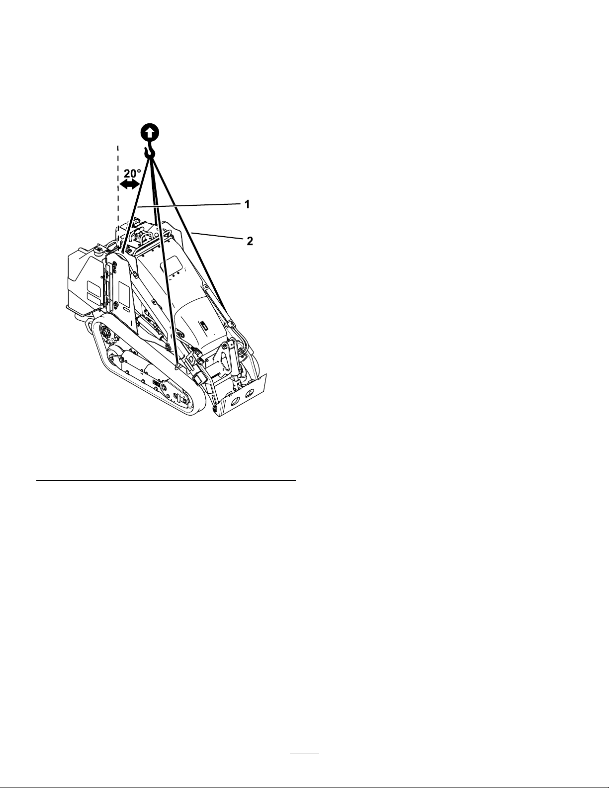
Removeanyattachmentsandliftthemachineusing
the4liftpoints.
Donotexceeda20-degreeanglewhenliftingthe
machine;usetheminimumchainlengthsprovided
below.
Figure32
1.Chainlengthforrearliftpoint(2)—118.9cm(46.8inches)
2.Chainlengthforfrontliftpoint(2)—206.2cm(81.2inches)
g377831
25

Maintenance
Note:Determinetheleftandrightsidesofthemachinefromthenormaloperatingposition.
MaintenanceSafety
CAUTION
Ifyouleavethekeyintheswitch,someonecouldaccidentlystarttheengineandseriously
injureyouorotherbystanders.
Removethekeyfromtheswitchbeforeyouperformanymaintenance.
•Parkthemachineonalevelsurface,disengage
theauxiliaryhydraulics,lowertheattachment,
engagetheparkingbrake(ifequipped),shut
offtheengine,andremovethekey.Waitforall
movementtostopandallowthemachinetocool
beforeadjusting,cleaning,storing,orrepairingit.
•Cleanupoilorfuelspills.
•Donotallowuntrainedpersonneltoservicethe
machine.
•Usejackstandstosupportthecomponentswhen
required.
•Carefullyreleasepressurefromcomponents
withstoredenergy;refertoRelievingHydraulic
Pressure(page47).
•Disconnectthebatterybeforemakinganyrepairs;
refertoUsingtheBattery-DisconnectSwitch(page
36).
RecommendedMaintenanceSchedule(s)
MaintenanceService
Interval
MaintenanceProcedure
•Keepyourhandsandfeetawayfromthemoving
parts.Ifpossible,donotmakeadjustmentswith
theenginerunning.
•Keepallpartsingoodworkingconditionandall
hardwaretightened.Replaceallwornordamaged
decals.
•Donottamperwiththesafetydevices.
•UseonlyToro-approvedattachments.
Attachmentscanchangethestabilityandthe
operatingcharacteristicsofthemachine.Youmay
voidthewarrantyifyouusethemachinewith
unapprovedattachments.
•UseonlygenuineT ororeplacementparts.
•Ifanymaintenanceorrepairrequirestheloader
armstobeintheraisedposition,securethearms
intheraisedpositionwiththehydraulic-cylinder
lock(s).
Aftertherst8hours
Aftertherst50hours
Beforeeachuseordaily
Every25hours
•Checkandadjustthetracktension.
•Replacethehydrauliclter.
•Checkandadjustthetracktension.
•Greasethemachine.(Greaseimmediatelyaftereverywashing.)
•Checktheair-lter-serviceindicator.
•Checktheengine-oillevel.
•Drainwaterandothercontaminantsfromthewaterseparator.
•Cleanthetracksandcheckforexcessivewearandpropertension.
•Cleanthescreen,oilcooler,andfrontoftheradiator(moreoftenindirtyordusty
conditions).
•Checkandcleantheradiatorscreen
•Checkthecoolantlevelintheexpansiontank.
•T esttheparkingbrake.
•Checkthealternator-beltconditionandtension.
•Removedebrisfromthemachine.
•Checkforloosefasteners.
•Removetheair-cleanercover,cleanoutdebris,andchecktheair-lter-service
indicator.
•Checkthehydraulic-uidlevel.
26

MaintenanceService
Interval
MaintenanceProcedure
Every50hours
Every100hours
Every250hours
Every400hours
Every500hours
Every1,500hoursor
2years,whichever
comesrst
Yearlyorbeforestorage
Every2years
•Checkthebatterycondition.
•Checkandadjustthetracktension.
•Checkthecoolingsystemhoses.
•Checkthehydrauliclinesforleaks,loosettings,kinkedlines,loosemounting
supports,wear,weather ,andchemicaldeterioration.
•Checkfordirtbuildupinthechassis.
•Changetheengineoilandlter.(Servicemorefrequentlyifconditionsareextremely
dustyorsandy .)
•Replacethehydrauliclter.
•Checkthefuellinesandconnectionsfordeterioration,damage,orlooseconnections.
•Replacetheairlter.
•Replacethewaterseparatorlter.
•Replacethein-linefuellter
•Changetheenginecoolant.
•Replacethealternatorbelt.(Refertotheengineowner’smanualforinstructions.)
•Changethehydraulicuid.
•Replaceallmovinghydraulichoses.
•Checkandadjustthetracktension.
•T ouchupchippedpaint.
•Drainandcleanthefueltank(s)—AuthorizedServiceDealeronly.
Important:Refertoyourengineowner’smanualforadditionalmaintenanceprocedures.
27
Pre-Maintenance
Procedures
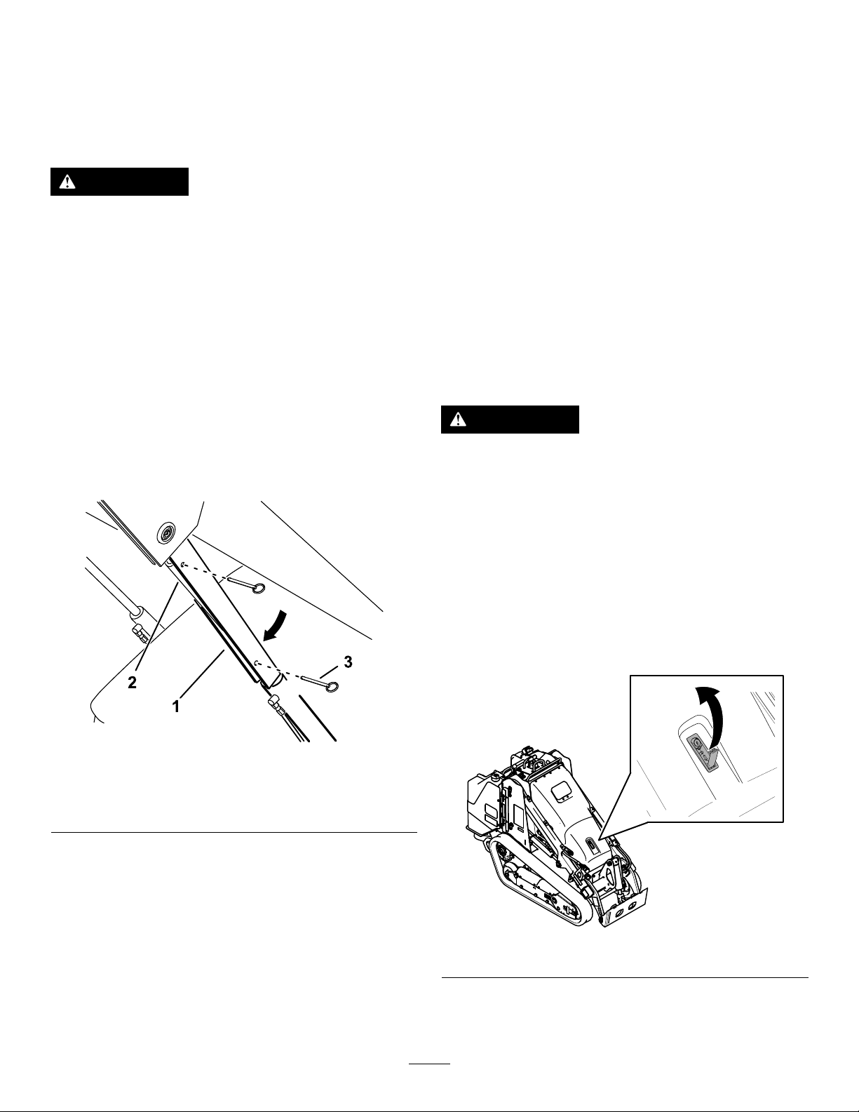
UsingtheCylinderLocks
RemovingandStoringthe
CylinderLocks
Important:Removethecylinderlocksfromthe
rodsandfullysecuretheminthestorageposition
beforeoperatingthemachine.
1.Starttheengine.
WARNING
Theloaderarmsmaylowerwhenintheraised
position,crushinganyoneunderthem.
Installthecylinderlock(s)beforeperforming
maintenancethatrequiresraisedloaderarms.
InstallingtheCylinderLocks
1.Removetheattachment.
2.Raisetheloaderarmstothefullyraisedposition.
3.Shutofftheengineandremovethekey.
4.Removethe2pinssecuringthecylinderlockto
thepostsonthesideofthemachine.
5.Slidethecylinderlockoverthelift-cylinderrod
(Figure33).
2.Raisetheloaderarmstothefullyraisedposition.
3.Shutofftheengineandremovethekey.
4.Removethepinssecuringthecylinderlocks.
5.Placethecylinderlocksonthepostsonthe
sidesofthemachineandsecurewiththepins.
6.Lowertheloaderarms.
AccessingInternal
Components
WARNING
Openingorremovingcovers,hoods,and
screenswhiletheengineisrunningcould
allowyoutocontactmovingparts,seriously
injuringyou.
Beforeopeninganyofthecovers,hoods,and
screens,shutofftheengine,removethekey
fromthekeyswitch,andallowtheengineto
cool.
Figure33
1.Cylinderlock3.Pin(2)
2.Lift-cylinderrod
6.Repeatstep4and5fortheothersideofthe
machine.
7.Slowlylowertheloaderarmsuntilthecylinder
lockscontactthecylinderbodiesandrodends.
8.Securetheloader-valvelock;referto
Loader-ValveLock(page13).
OpeningtheHood
1.Usethelatchkeytounlockthelever.
g365284
g365296
Figure34
2.Usethelevertoliftopenthehood
3.Securetheproprod.
28
 Loading...