

FormNo.3422-276RevA
320-DCompactToolCarrier
ModelNo.22337CP—SerialNo.401350000andUp
Registeratwww.T oro.com.
OriginalInstructions(EN)
*3422-276*A
ThisproductcomplieswithallrelevantEuropean
directives;fordetails,pleaseseetheseparateproduct
specicDeclarationofConformity(DOC)sheet.
ItisaviolationofCaliforniaPublicResourceCode
Section4442or4443touseoroperatetheengineon
anyforest-covered,brush-covered,orgrass-covered
landunlesstheengineisequippedwithaspark
arrester,asdenedinSection4442,maintainedin
effectiveworkingorderortheengineisconstructed,
equipped,andmaintainedforthepreventionofre.
Theenclosedengineowner'smanualissupplied
forinformationregardingtheUSEnvironmental
ProtectionAgency(EPA)andtheCaliforniaEmission
ControlRegulationofemissionsystems,maintenance,
andwarranty.Replacementsmaybeorderedthrough
theenginemanufacturer.
WARNING
CALIFORNIA
Proposition65Warning
Dieselengineexhaustandsomeofits
constituentsareknowntotheStateof
Californiatocausecancer,birthdefects,
andotherreproductiveharm.
Batteryposts,terminals,andrelated
accessoriescontainleadandlead
compounds,chemicalsknownto
theStateofCaliforniatocause
cancerandreproductiveharm.Wash
handsafterhandling.
Useofthisproductmaycauseexposure
tochemicalsknowntotheStateof
Californiatocausecancer,birthdefects,
orotherreproductiveharm.
accessoryinformation,helpndingadealer,orto
registeryourproduct.
Wheneveryouneedservice,genuineToroparts,or
additionalinformation,contactanAuthorizedService
DealerorToroCustomerServiceandhavethemodel
andserialnumbersofyourproductready.Figure1
identiesthelocationofthemodelandserialnumbers
ontheproduct.Writethenumbersinthespace
provided.
Important:Withyourmobiledevice,youcan
scantheQRcodeontheserialnumberdecal(if
equipped)toaccesswarranty,parts,andother
productinformation.
g237186
Figure1
1.Modelandserialnumberlocation
ModelNo.
SerialNo.
Thismanualidentiespotentialhazardsandhas
safetymessagesidentiedbythesafety-alertsymbol
(Figure2),whichsignalsahazardthatmaycause
seriousinjuryordeathifyoudonotfollowthe
recommendedprecautions.
Introduction
Thismachineisacompacttoolcarrierintendedfor
useinvariousearthandmaterialsmovingactivitiesfor
landscapingandconstructionwork.Itisdesignedto
operateawidevarietyofattachmentseachofwhich
performaspecializedfunction.
Readthisinformationcarefullytolearnhowtooperate
andmaintainyourproductproperlyandtoavoid
injuryandproductdamage.Youareresponsiblefor
operatingtheproductproperlyandsafely.
YoumaycontactT orodirectlyatwww.T oro.com
forproductsafetyandoperationtrainingmaterials,
©2018—TheToro®Company
8111LyndaleAvenueSouth
Bloomington,MN55420
Figure2
1.Safety-alertsymbol
Thismanualuses2wordstohighlightinformation.
Importantcallsattentiontospecialmechanical
informationandNoteemphasizesgeneralinformation
worthyofspecialattention.
2
g000502
Contactusatwww.Toro.com.
PrintedintheUSA
AllRightsReserved

Contents
Safety.......................................................................4
GeneralSafety...................................................4
SafetyandInstructionalDecals..........................5
Setup........................................................................9
1InstallingtheSpeed-SelectorLever..................9
2CheckingtheFluidLevelsandTire
Pressure.........................................................9
3ChargingtheBattery......................................10
4SettingtheEngineSpeed..............................10
ProductOverview....................................................11
Controls...........................................................12
Specications..................................................14
Attachments/Accessories.................................14
BeforeOperation.................................................15
BeforeOperationSafety...................................15
AddingFuel......................................................15
PerformingDailyMaintenance..........................16
AdjustingtheThighSupport..............................16
DuringOperation.................................................17
DuringOperationSafety...................................17
StartingtheEngine...........................................18
DrivingtheMachine..........................................18
ShuttingOfftheEngine.....................................18
UsingAttachments...........................................19
AfterOperation....................................................21
AfterOperationSafety......................................21
MovingaNon-FunctioningMachine..................21
TransportingtheMachine.................................21
LiftingtheMachine...........................................23
Maintenance...........................................................24
RecommendedMaintenanceSchedule(s)...........24
Pre-MaintenanceProcedures..............................25
MaintenanceSafety..........................................25
UsingtheCylinderLocks..................................25
AccessingInternalComponents.......................26
Lubrication..........................................................27
GreasingtheMachine.......................................27
EngineMaintenance...........................................27
EngineSafety...................................................27
ServicingtheAirCleaner..................................27
ServicingtheEngineOil....................................28
FuelSystemMaintenance...................................30
DrainingWaterfromtheFuelFilter....................30
ChangingtheFuelFilter....................................30
BleedingtheFuelSystem.................................31
DrainingtheFuelT ank......................................31
ElectricalSystemMaintenance...........................32
ElectricalSystemSafety...................................32
ServicingtheBattery.........................................32
DriveSystemMaintenance..................................34
CheckingtheTirePressure...............................34
CheckingtheWheel-LugNuts..........................34
CoolingSystemMaintenance..............................34
CoolingSystemSafety.....................................34
CleaningtheRadiatorScreen...........................34
CheckingtheEngine-CoolantLevel..................34
ChangingtheEngineCoolant...........................35
BrakeMaintenance.............................................35
TestingtheParkingBrake.................................35
HydraulicSystemMaintenance...........................36
HydraulicSystemSafety...................................36
HydraulicFluidSpecications...........................36
CheckingtheHydraulic-FluidLevel...................36
ReplacingtheHydraulicFilter...........................37
ChangingtheHydraulicFluid............................37
Cleaning..............................................................38
RemovingDebris..............................................38
Storage...................................................................38
StorageSafety..................................................38
Storage.............................................................38
Troubleshooting......................................................39
Schematics.............................................................43
3

Safety
DANGER
Theremaybeburiedutilitylinesinthework
area.Diggingintothemmaycauseashock
oranexplosion.
Havethepropertyorworkareamarkedfor
buriedlinesanddonotdiginmarkedareas.
Contactyourlocalmarkingserviceorutility
companytohavethepropertymarked(for
example,intheUS,call811orinAustralia,
call1100forthenationwidemarkingservice).
GeneralSafety
Alwaysfollowallsafetyinstructionstoavoidserious
injuryordeath.Usingthisproductforpurposesother
thanitsintendedusecouldprovedangeroustoyou
andbystanders.
•Donotcarryaloadwiththearmsraised;always
carryloadsclosetotheground.
•Keepbystandersandpetsasafedistanceaway
fromthemachine.
•Stopthemachine,shutofftheengine,andremove
thekeybeforeservicing,fueling,orunclogging
themachine.
Improperlyusingormaintainingthismachinecan
resultininjury .Toreducethepotentialforinjury ,
complywiththesesafetyinstructionsandalwayspay
attentiontothesafety-alertsymbol,whichmeans
Caution,Warning,orDanger—personalsafety
instruction.Failuretocomplywiththeseinstructions
mayresultinpersonalinjuryordeath.
Youcanndadditionalsafetyinformationwhere
neededthroughoutthismanual.
•Slopesareamajorfactorrelatedtoloss-of-control
andtip-overaccidents,whichcanresultinsevere
injuryordeath.Operatingthemachineonany
slopeoruneventerrainrequiresextracaution.
•Operatethemachineupanddownslopeswith
theheavyendofthemachineuphillandtheload
closetotheground.Weightdistributionchanges
withattachments.Anemptybucketmakesthe
rearofthemachinetheheavyend,andafull
bucketmakesthefrontofthemachinetheheavy
end.Mostotherattachmentsmakethefrontofthe
machinetheheavyend.
•Havethepropertyorworkareamarkedforburied
linesandotherobjects,anddonotdiginmarked
areas.
•ReadandunderstandthecontentofthisOperator’s
Manualbeforestartingtheengine.
•Useyourfullattentionwhileoperatingthe
machine.Donotengageinanyactivitythat
causesdistractions;otherwise,injuryorproperty
damagemayoccur.
•Neverallowchildrenoruntrainedpeopleto
operatethemachine.
•Keepyourhandsandfeetawayfromthemoving
componentsandattachments.
•Donotoperatethemachinewithouttheguards
andothersafetyprotectivedevicesinplaceand
workingonthemachine.
4
SafetyandInstructionalDecals
Safetydecalsandinstructionsareeasilyvisibletotheoperatorandarelocatednearanyarea
ofpotentialdanger.Replaceanydecalthatisdamagedormissing.
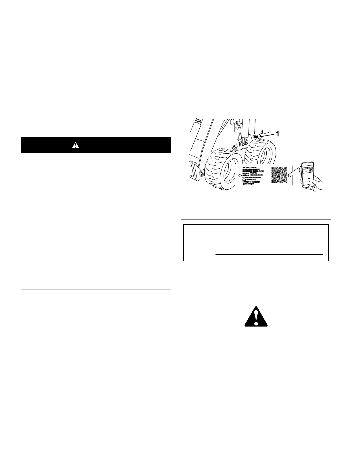
decal93-7814
93-7814
BatterySymbols
Someorallofthesesymbolsareonyourbattery.
1.Explosionhazard
2.Nore,opename,or
smoking
3.Causticliquid/chemical
burnhazard
4.Weareyeprotection.9.Flusheyesimmediately
5.ReadtheOperator's
Manual.
6.Keepbystandersasafe
distanceawayfromthe
battery.
7.Weareyeprotection;
explosivegasescan
causeblindnessandother
injuries.
8.Batteryacidcancause
blindnessorsevereburns.
withwaterandgetmedical
helpfast.
10.Containslead;donot
discard
93-6680
decalbatterysymbols
decal93-9084
93-9084
1.Entanglementhazard,belt—stayawayfrommovingparts.
1.Liftpoint/Tie-downpoint
decal98-4387
98-4387
decal93-6680
1.Warning—wearhearingprotection.
1.Hydraulicuid
2.ReadtheOperator'sManual.
decal93-6686
93-6686
decal98-8219
98-8219
1.Fast
2.Throttle
3.Slow
5
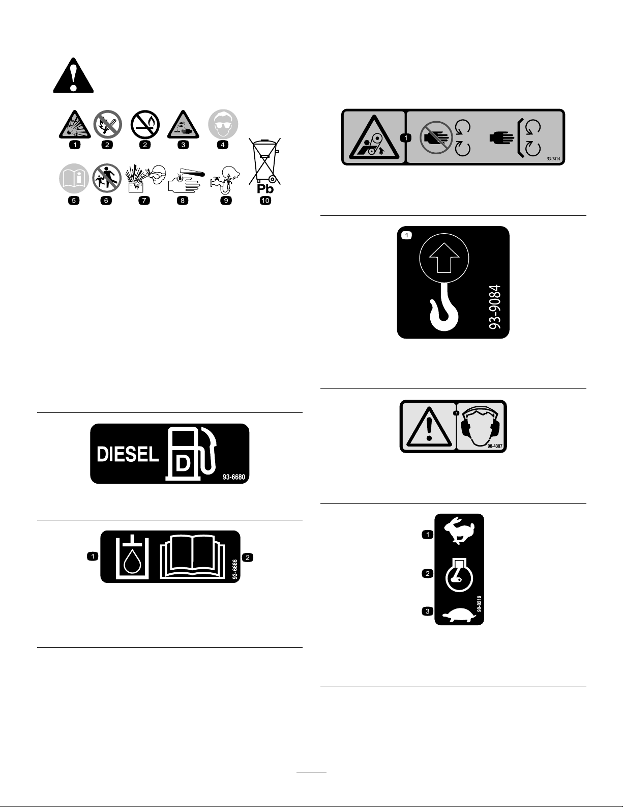
98-8235
1.Fast
2.Tractiondrive
100-1692
1.Brakeengaged3.Brakedisengaged
2.Parkingbrake
100-1703
1.Speedselector
decal98-8235
3.Slow
1.Auxiliaryhydraulics
2.Lockedreverse(detent)
decal100-1692
108-4723
3.Neutral(off)
4.Forward
decal108-4723
decal120-0627
120-0627
1.Cutting/dismembermenthazard,fan—stayawayfrom
movingparts;keepallguardsandshieldsinplace.
decal100-1703
decal130-2836
130-2836
1.Enginecoolantunder
pressure
2.Explosionhazard—read
theOperator’sManual.
106-5976
3.Warning—donottouchthe
hotsurface.
4.Warning—readthe
Operator’sManual.
1.Crushinghazard;cuttinghazard—keepawayfromthe
bucketandtheliftarm.
decal106-5976
decal130-2837
130-2837
1.Warning—donotcarrypassengersontheattachment.
6
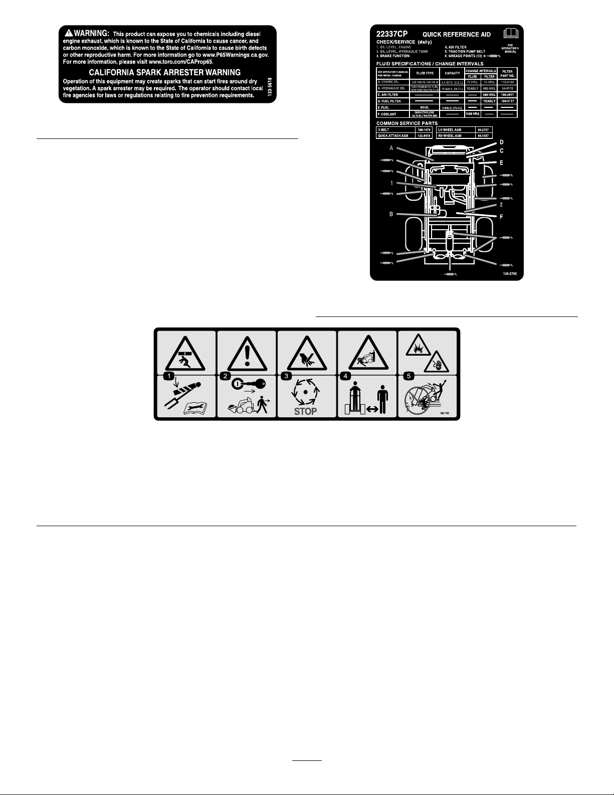
decal133-5618
133-5618
decal136-5785
136-5785
100-1701
1.Crushinghazard—installthecylinderlockandreadtheinstructionsbeforeservicingorperformingmaintenance.
2.Warning—removethekeyandlowertheloaderarmsbeforeleavingthemachine.
3.Cuttinghazardofhand—waitformovingpartstostop.
4.Crushing/dismembermenthazardofbystanders—keepbystandersasafedistanceawayfromthemachine.
5.Explosionandelectricalshockhazards—donotdiginareaswithburiedgasorelectricallines.
decal100-1701
7

decal108-9733
108-9733
1.Warning—readthe
Operator'sManual.
2.Tippinghazard—donot
stepoffoperatorplatform
withloadraised;always
operatewiththeheavyend
ofthemachinepointed
uphill;carryloadslow;
neverjerkthecontrols;
useasteady,evenmotion;
maximumloadis234kg
(515lb).
3.Armlift—down
4.Armlift—up
5.Wheeldrive—forward
6.Wheeldrive—reverse9.Engine—start
7.Buckettilt—down10.Engine—run
8.Buckettilt—up11.Engine—stop
8
Setup
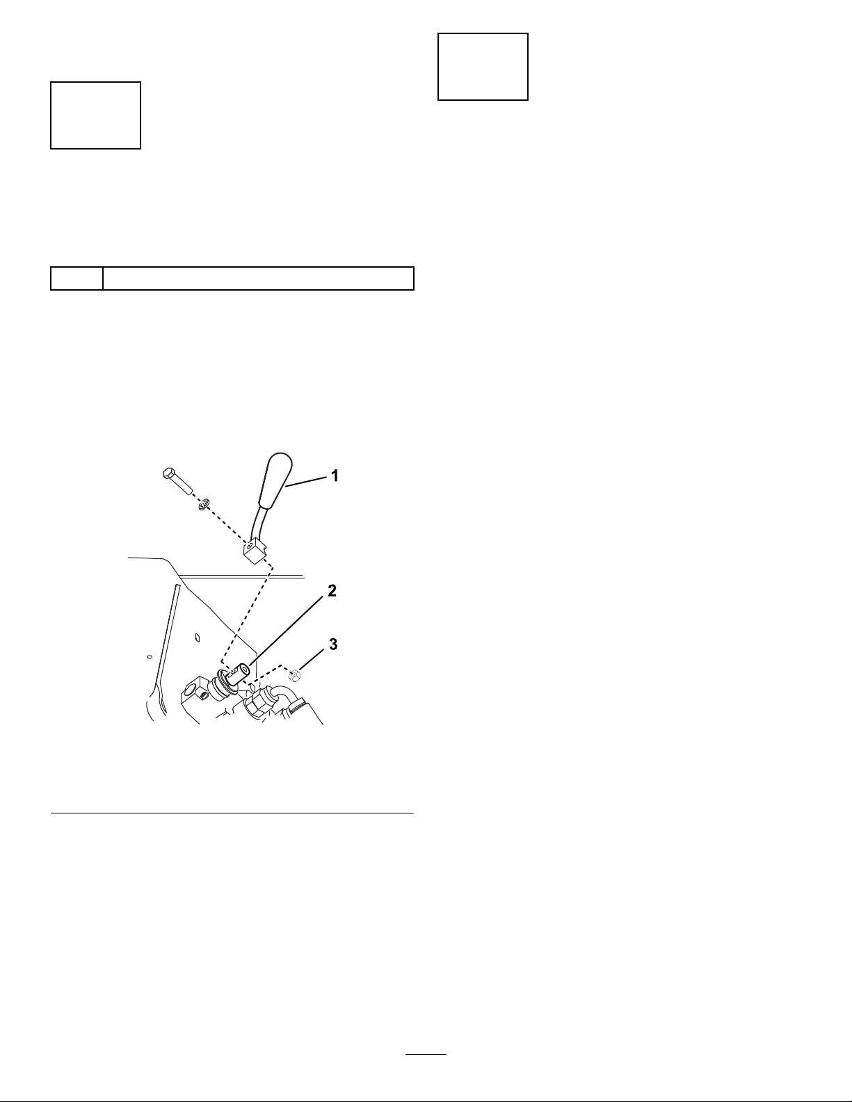
2
1
Installingthe Speed-SelectorLever
Partsneededforthisprocedure:
1
Speed-selectorlever
Procedure
1.Removeanddiscardthenutsecuringthebolt
andlockwashertothespeed-selectorlever.
2.Securethelevertothespeed-selectorvalve
usingthebolt,lockwasher,andnutasillustrated
inFigure3.
CheckingtheFluidLevels andTirePressure
NoPartsRequired
Procedure
Beforestartingtheengineforthersttime,checkthe
engine-oillevel,hydraulic-uidlevel,engine-coolant
level,andthetirepressure.Refertothefollowing
sectionsformoreinformation:
•CheckingtheEngine-OilLevel(page28)
•CheckingtheHydraulic-FluidLevel(page36)
•CheckingtheEngine-CoolantLevel(page34)
•CheckingtheTirePressure(page34)
1.Speed-selectorlever
2.Speed-selectorvalve
g230938
Figure3
3.Nut
9
3
ChargingtheBattery
NoPartsRequired
Procedure
Chargeandinstallthebattery;refertoChargingthe
Battery(page33).
4
SettingtheEngineSpeed
CEMachinesOnly
Partsneededforthisprocedure:
1Aluminumtube
Procedure
Ifyouaresettingupthismachineforuseinthe
EuropeanCommunity(CE),youmustpermanently
adjusttheenginespeedsothatitisnomorethan
3,200rpm,asfollows:
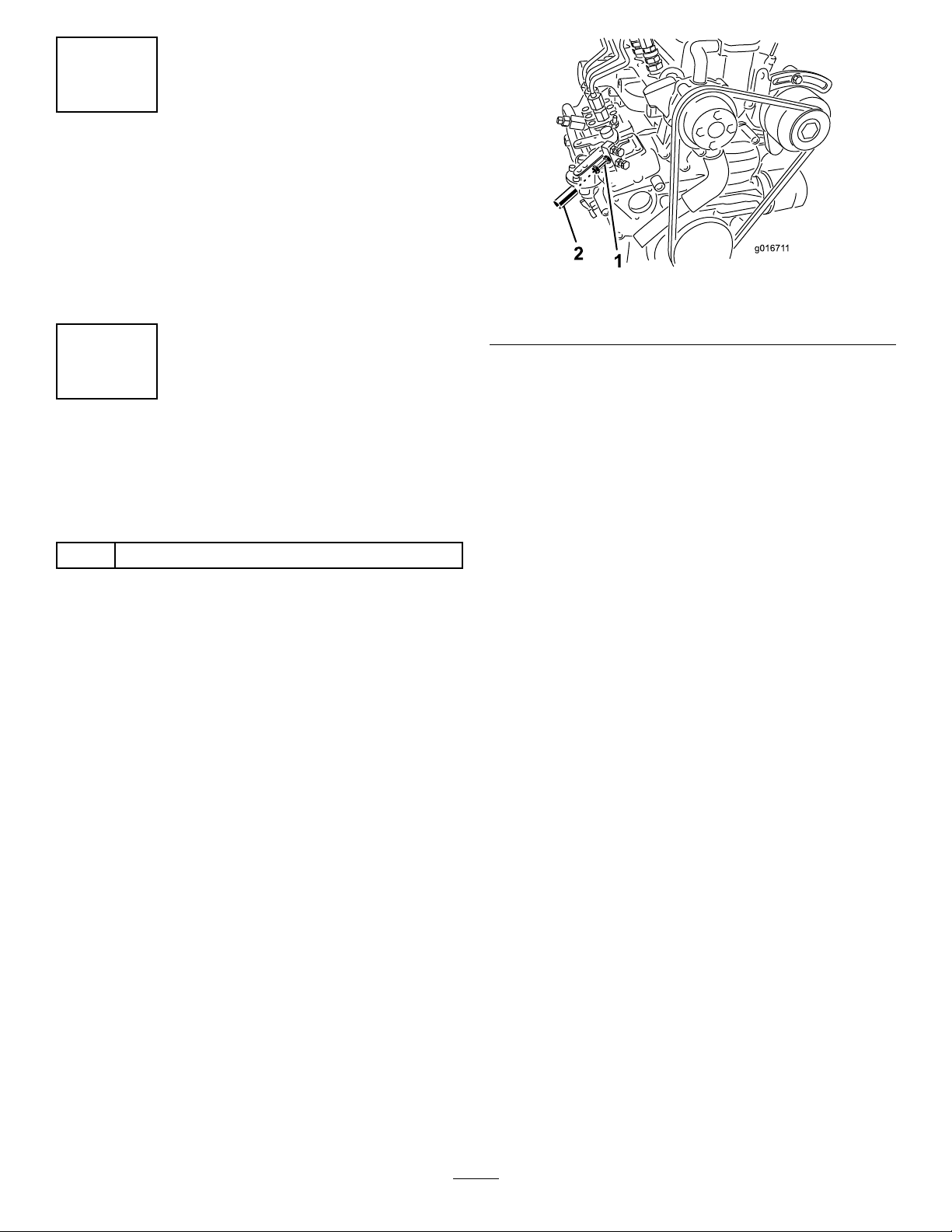
g016711
Figure4
1.Throttle-adjustmentscrew2.Aluminumtube
4.Shutofftheengine.
5.Slideanaluminumtubeoverthe
throttle-adjustmentscrewandjamnut
(Figure4)andcrimpitdownoverthescrewso
thatthescrewcannotbeadjustedagain.
Important:Thetubemustbefullyoverthe
jamnuttopreventaccesstoit.
6.Closetherear-accesscoverandsecureitwith
thelanyardfastener.
1.Starttheengineandrunitathalfthrottlefor5to
10minutestowarmitup.
Important:Theenginemustbewarmbefore
makingthisadjustment.
2.MovethethrottletotheFASTposition.
3.Usingatachometerandthethrottle-adjustment
screwontheengine(Figure4),settheengine
speedto3,200rpmmaximum,thentightenthe
jamnutontheadjustingscrew.
Important:Iftheenginespeedexceeds
3,200rpm,theengineisnotincompliance
withCEregulationsandcannotbelegally
soldorusedintheEuropeanCommunity.
10
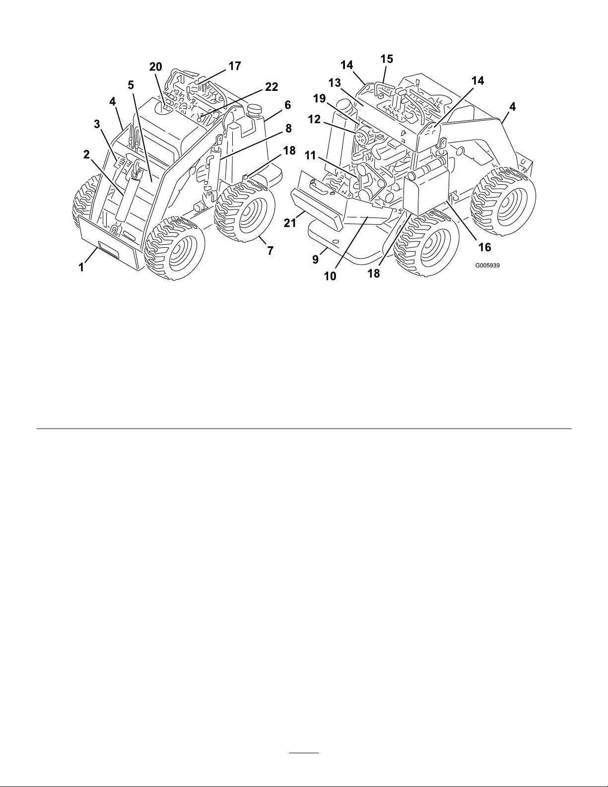
ProductOverview
g005939
Figure5
1.Mountplate7.Wheel
2.Tiltcylinder
3.Auxiliary-hydrauliccouplers
4.Loaderarms
5.Front-accesscover11.Engine17.Indicatorlights
6.Fueltank
8.Liftcylinder14.Liftpoints20.Radiator-llcap
9.Operatorplatform
(removablecounterweight
notshown)
10.Rear-accesscover(open)
12.Airlter18.Towvalves(underfueltank
13.Controlpanel
15.Handle21.Thighsupport
16.Battery22.Flow-dividercontrol
andbattery)
19.Parking-brakelever
11
Controls
Becomefamiliarwithallthecontrols(Figure6)before
youstarttheengineandoperatethemachine.
ControlPanel
Loader-ArmLever
•Tolowertheloaderarms,slowlypushthe
loader-armleverforward.
•Toraisetheloaderarms,slowlypulltheloader-arm
leverrearward.
Loader-ValveLock
Theloader-valvelocksecurestheloader-armand
attachment-tiltleverssothatyoucannotpushthem
forward.Thishelpstoensurethatnooneaccidentally
lowerstheloaderarmsduringmaintenance.Secure
theloaderarmswiththelockanytimeyouneedto
shutoffthemachinewiththeloaderarmsraised.
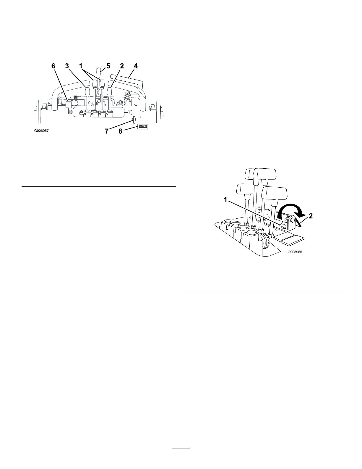
Figure6
1.Traction-controllevers
2.Attachment-tiltlever6.Throttlelever
3.Loader-armlever7.Keyswitch
4.Auxiliary-hydraulicslever8.Hourmeter
5.Speed-selectorlever
KeySwitch
Thekeyswitch,usedtostartandshutofftheengine,
has3positions:OFF,RUN,andSTART.Referto
StartingtheEngine(page18).
ThrottleLever
Movethecontrolforwardtoincreasetheenginespeed
andrearwardtodecreasespeed.
Traction-ControlLevers
•Tomoveforward,movethetraction-controllevers
forward.
•Tomoverearward,movethetraction-controllevers
rearward.
•Toturn,movetheleverlocatedonthesideyou
wanttoturnbacktowardtheNEUTRALposition
whilekeepingtheotherleverengaged.
Note:Thefartheryoumovethetraction-control
leversineitherdirection,thefasterthemachine
movesinthatdirection.
•Tosloworstop,movethetraction-controllevers
totheNEUTRALposition.
g006057
Tosetthelock,pullitbackandallthewaydown
againstthelevers(Figure7).
Note:Y oumustmovetheleversrearwardtoengage
ordisengagetheloader-valvelock.
g005955
Figure7
1.Loader-valvelock
(engaged)
2.Loader-valvelock
(disengaged)
Auxiliary-HydraulicsLever
•Tooperateahydraulicattachmentintheforward
direction,slowlypulltheauxiliary-hydraulicslever
upwardandthenrearward.
•Tooperateahydraulicattachmentinthereverse
direction,slowlypulltheauxiliary-hydraulicslever
upwardandthenpushitforward.Thisisalso
calledtheDETENTpositionbecauseitdoesnot
requireoperatorpresence.
Attachment-TiltLever
•Totilttheattachmentforward,slowlypushthe
attachment-tiltleverforward.
•Totilttheattachmentrearward,slowlypullthe
attachment-tiltleverrearward.
12
Speed-SelectorLever
Flow-DividerControl
•Tosetthetractiondrive,loaderarms,and
attachmenttilttohighspeedandtheauxiliary
hydraulicstolowspeed,movethespeed-selector
levertotheFORWARDposition.
•Tosettheauxiliaryhydraulicstohighspeedand
thetractiondrive,loaderarms,andattachmenttilt
tolowspeed,movethespeed-selectorleverto
theREARWARDposition.
WARNING
Ifyoumovethespeed-selectorleverwhilethe
machineisinmotion,themachinewilleither
stopsuddenlyoracceleratequickly .Ifyou
operatethemachinewiththespeed-selector
leverinanintermediateposition,themachine
willoperateerraticallyandmaybedamaged.
Youcouldlosecontrolofthemachineand
injurebystandersoryourself.
•Donotmovethespeed-selectorleverwhen
themachineisinmotion.
•Donotoperatethemachinewhenthe
speedselectorisinanyintermediate
position(i.e.,anypositionotherthanfully
forwardorfullyrearward).
HourMeter
Thehourmeterdisplaysthenumberofhoursof
operationloggedonthemachine.
After50hoursandevery75hoursthereafter(i.e.,50,
125,200,etc.)thehourmeterdisplaysSVConthe
lowerleftsideofthescreentoremindyoutochange
theengineoilandperformtherequiredmaintenance.
Afterevery400hours(i.e.,400,800,1200,etc.),
thehourmeterdisplaysSVConthelowerright
sideofthescreentoremindyoutoperformthe
othermaintenanceproceduresbasedona400-hour
schedule.
Note:Thesereminderscomeonstarting3hours
priortotheserviceintervaltimeandashatregular
intervalsfor6hours.
Thetractionunithydraulics(i.e.,thetractiondrive,
loaderarms,andattachmenttilt)workonaseparate
hydrauliccircuitfromtheauxiliaryhydraulicsfor
poweringattachments;however,the2systemsshare
thesamehydraulicpumps.Usingtheow-divider
control(Figure8),youcanvarythespeedofthe
tractionunithydraulicsbydivertinghydraulicowto
theauxiliary-hydraulicscircuit.Therefore,themore
hydraulicowyoudiverttotheauxiliaryhydraulics,
theslowerthetractionunithydraulicsmove.
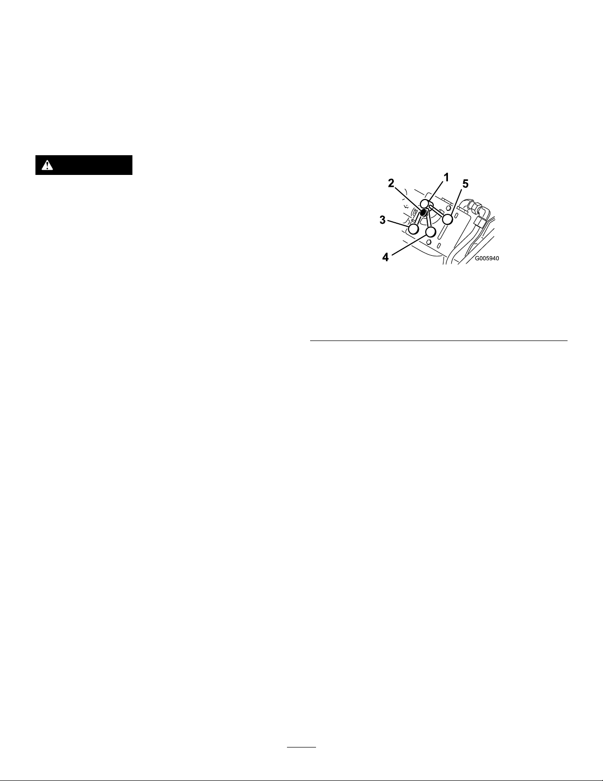
g005940
Figure8
1.Flow-dividercontrol4.10to11o'clockposition
2.Knob5.9o'clockposition
3.12o'clockposition
•Movetheow-dividercontroltothe12o'clock
positiontoprovidemaximumspeedtothetraction
unithydraulics.
Usethissettingforfastoperationofthetraction
unit.
•Movetheow-dividercontrolbetweenthe12
o'clockand9o'clockpositionstoslowthetraction
unithydraulicsandne-tunethespeed.
Useasettinginthisrangewithattachments
withhydraulicswhereyouneedtobothrunthe
attachmentandmovethetractionunithydraulics,
suchastheauger,boringunit,hydraulicblade,
andtiller.
•Movethecontroltothe9o'clockpositionto
transferallhydraulicowtotheauxiliaryhydraulics
oftheattachment.
Inthissetting,thetractionunithydraulicsdonot
work.Usethissettingwithhydraulicattachments
thatdonotrequirethetractionunithydraulics.
Thetrencherworksbestifyousetitcloseto9
o'clocksothatthetractionunitcreepsslowlywhen
trenching.
Note:Theow-dividercontrolcanbexedinplace
byturningtheknobonthecontrolclockwiseuntilit
contactsthedial(Figure8).
13
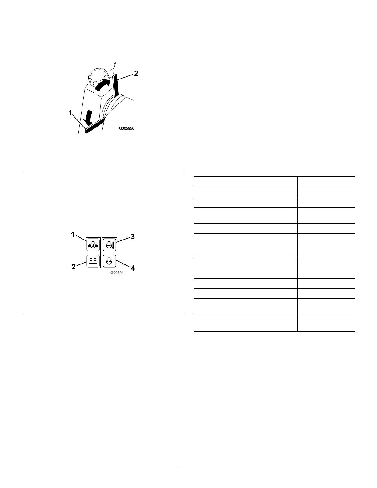
Parking-BrakeLever
•Toengagetheparkingbrake,rotatethelever
down(Figure9).
•Toreleasetheparkingbrake,rotatetheleverup
(Figure9).
Figure9
1.Parking-brake
lever—engaged
2.Parking-brake
lever—disengaged
•BatteryLight
Thislightisonforafewsecondswheneveryou
starttheengine.Ifthebatterylightisonwhile
theengineisrunning,thealternator,battery ,
orelectricalsystemisbroken.Contactyour
AuthorizedT oroDealerfordiagnosticsandrepair.
•Glow-PlugLight
ThislightisonwhenthekeyisturnedtoRUN
beforestartingtheengine.Theglow-pluglight
remainsonforupto10seconds,indicating
thattheglowplugsarewarmingtheengine.
Iftheglow-pluglightisonwhiletheengineis
running,theglowplugsarebroken.Contactyour
AuthorizedT oroDealerfordiagnosticsandrepair.
g005956
Specications
Note:Specicationsanddesignaresubjectto
changewithoutnotice.
IndicatorLights
Theindicatorlightswarnyouinthecaseofasystem
malfunctionand,inthecaseoftheglow-pluglight,
indicatethattheglowplugsareon.Figure10
illustratesthe4indicatorlights.
Figure10
1.Oil-pressurelight
2.Batterylight
•Engine-TemperatureLight
Iftheengine-temperaturelightison,theengine
isoverheating.Shutofftheengineandallowthe
machinetocooldown.Checkthecoolantlevel
andthebeltstothefanandwaterpump.Fill
thecoolantasrequiredandreplaceanywornor
slippingbelts.Iftheproblempersists,contactyour
AuthorizedT oroDealerfordiagnosticsandrepair.
•Oil-PressureLight
Thislightisonforafewsecondswheneveryou
starttheengine.Iftheoil-pressurelightisonwhile
theengineisrunning,theengine-oilpressureis
low.Shutofftheengineandallowthemachine
tocooldown.Checktheoillevelandllthe
crankcasewithoilasneeded.Iftheproblem
persists,contactyourAuthorizedToroDealerfor
diagnosticsandrepair.
3.Engine-temperaturelight
4.Glow-pluglight
Width
Length
Height
Weight(withoutattachmentor
counterweight)
Weightofthecounterweight227kg(500lb)
Operatingcapacity—with74.8kg(165
lb)operator,thestandardbucket,and
withoutthecounterweight
Tippingcapacity—with74.8kg(165
lb)operator,thestandardbucket,and
g005941
withoutthecounterweight
Wheelbase
Dumpheight(withstandardbucket)120cm(47inches)
Reach—fullyraised(withstandard
bucket)
Heighttohingepin(narrowbucketin
standardposition)
103cm(41inches)
152cm(60inches)
125cm(49inches)
783kg(1,722lb)
227kg(500lb)
454kg(1,000lb)
71cm(28inches)
66cm(26inches)
168cm(66inches)
Attachments/Accessories
AselectionofT oroapprovedattachmentsand
accessoriesisavailableforusewiththemachine
toenhanceandexpanditscapabilities.Contact
yourAuthorizedServiceDealerorauthorizedT oro
distributororgotowww.Toro.comforalistofall
approvedattachmentsandaccessories.
Toensureoptimumperformanceandcontinuedsafety
certicationofthemachine,useonlygenuineT oro
replacementpartsandaccessories.Replacement
partsandaccessoriesmadebyothermanufacturers
couldbedangerous,andsuchusecouldvoidthe
productwarranty.
14

Operation
BeforeOperation
BeforeOperationSafety
•Donotaddordrainfuelinanenclosedspace.
•Donotstorethemachineorfuelcontainerwhere
thereisanopename,spark,orpilotlight,such
asonawaterheaterorotherappliance.
•Ifyouspillfuel,donotattempttostarttheengine;
avoidcreatinganysourceofignitionuntilthefuel
vaporshavedissipated.
GeneralSafety
•Neverallowchildrenoruntrainedpeopleto
operateorservicethemachine.Localregulations
mayrestricttheageorrequirecertiedtrainingof
theoperator.Theownerisresponsiblefortraining
alloperatorsandmechanics.
•Becomefamiliarwiththesafeoperationofthe
equipment,operatorcontrols,andsafetydecals.
•Knowhowtostopthemachineandshutoffthe
enginequickly.
•Checkthattheoperator'spresencecontrols,safety
switches,andshieldsareattachedandfunctioning
properly.Donotoperatethemachineunlessthey
arefunctioningproperly.
•Locatethepinch-pointareasmarkedonthe
machineandattachments;keepyourhandsand
feetawayfromtheseareas.
•Beforeoperatingthemachinewithanattachment,
ensurethattheattachmentisproperlyinstalled
andthatitisagenuineToroattachment.Readall
theattachmentmanuals.
•Evaluatetheterraintodeterminewhataccessories
andattachmentsyouneedtoproperlyandsafely
performthejob.
•Havethepropertyorworkareamarkedforburied
linesandotherobjects,anddonotdiginmarked
areas;notethelocationofunmarkedobjectsand
structures,suchasundergroundstoragetanks,
wells,andsepticsystems.
AddingFuel
RecommendedFuel
Useonlyclean,freshdieselfuelorbiodieselfuelswith
low(<500ppm)orultralow(<15ppm)sulfurcontent.
Theminimumcetaneratingshouldbe40.Purchase
fuelinquantitiesthatyoucanusewithin180daysto
ensurefuelfreshness.
Usesummer-gradedieselfuel(No.2-D)at
temperaturesabove-7°C(20°F)andwintergrade
(No.1-DorNo.1-D/2-Dblend)belowthat
temperature.Usingwinter-gradefuelatlower
temperaturesprovideslowerashpointandcoldow
characteristics,whicheasesstartingandreducesfuel
lterplugging.
Usingsummer-gradefuelabove-7°C(20°F)
contributestowardlongerfuelpumplifeandincreased
powercomparedtowinter-gradefuel.
Important:Donotusekeroseneorgasoline
insteadofdieselfuel.Failuretoobservethis
cautionwilldamagetheengine.
BiodieselReady
Thismachinecanalsouseabiodieselblendedfuel
ofuptoB20(20%biodiesel,80%petrodiesel).The
petrodieselportionshouldbeloworultralowsulfur.
Observethefollowingprecautions:
•Inspecttheareawhereyouwillusetheequipment
andremovealldebris.
•Ensurethattheareaisclearofbystandersbefore
operatingthemachine.Stopthemachineif
anyoneentersthearea.
FuelSafety
•Useextracarewhenhandlingfuel.Itisammable
anditsvaporsareexplosive.
•Extinguishallcigarettes,cigars,pipes,andother
sourcesofignition.
•Useonlyanapprovedfuelcontainer.
•Donotremovethefuelcaporllthefueltank
whiletheengineisrunningorhot.
•Thebiodieselportionofthefuelmustmeet
specicationASTMD6751orEN14214.
•TheblendedfuelcompositionshouldmeetASTM
D975orEN590.
•Paintedsurfacesmaybedamagedbybiodiesel
blends.
•UseB5(biodieselcontentof5%)orlesserblends
incoldweather.
•Monitorseals,hoses,gasketsincontactwithfuel
astheymaydegradeovertime.
•Fuellterpluggingmayoccurforatimeafter
convertingtobiodieselblends.
•Contactyourdistributorformoreinformationon
biodiesel.
15

FillingtheFuelTank(s)
1.Parkthemachineonalevelsurface,engage
theparkingbrake(ifequipped),andlowerthe
loaderarms.
2.Shutofftheengine,removethekey,andallow
theenginetocool.
3.Cleanaroundthefuel-tankcapandremoveit
(Figure11).
Figure11
AdjustingtheThigh Support
Toadjustthethighsupport(Figure12),loosen
theknobsandraiseorlowerthesupportpadto
thedesiredheight.Youcanalsoobtainadditional
adjustmentbylooseningthenutsecuringthepad
totheadjustmentplateandmovingtheplateupor
downasneeded.Tightenallfastenerssecurelywhen
nished.
g237886
1.Fuel-tankcap
4.Fillthetanktoabout2.5cm(1inch)belowthe
topofthetank,notthellerneck,withfuel.
Important:Thisspaceinthetankallows
fueltoexpand.Donotllthefueltank
completelyfull.
5.Installthefuel-tankcapsecurely,turningituntil
itclicks.
6.Wipeupanyspilledfuel.
PerformingDaily Maintenance
Beforestartingthemachineeachday,performthe
EachUse/DailyprocedureslistedintheMaintenance
(page24).
Important:Checkthehydraulic-uidlevel
andbleedthefuelsystembeforestartingthe
engineforthersttime;refertoCheckingthe
Hydraulic-FluidLevel(page36)andBleedingthe
FuelSystem(page31).
1.Thigh-supportbracket
2.Adjustmentplate
3.Thigh-supportpad
g006054
Figure12
4.Knobandatwasher
5.Carriagebolt
6.Locknutandatwasher
16

DuringOperation
DuringOperationSafety
GeneralSafety
•Donotcarryaloadwiththearmsraised.Always
carryloadsclosetotheground.
•Donotexceedtheratedoperatingcapacity,asthe
machinemaybecomeunstable,whichmayresult
inlossofcontrol.
•UseonlyToro-approvedattachmentsand
accessories.Attachmentscanchangethestability
andtheoperatingcharacteristicsofthemachine.
•Formachineswithaplatform:
–Lowertheloaderarmsbeforesteppingoffthe
platform.
–Donottrytostabilizethemachinebyputting
yourfootontheground.Ifyoulosecontrolof
themachine,stepofftheplatformandaway
fromthemachine.
–Donotplaceyourfeetundertheplatform.
–Donotmovethemachineunlessyouare
standingwithbothfeetontheplatformandyour
handsareholdingontothereferencebars.
•Useyourfullattentionwhileoperatingthe
machine.Donotengageinanyactivitythat
causesdistractions;otherwise,injuryorproperty
damagemayoccur.
•Lookbehindanddownbeforebackingupto
ensurethatthepathisclear.
•Neverjerkthecontrols;useasteadymotion.
•Theowner/usercanpreventandisresponsible
foraccidentsthatmaycausepersonalinjuryor
propertydamage.
•Wearappropriateclothingincludinggloves,eye
protection,longpants,substantialslip-resistant
footwear,andhearingprotection.Tiebacklong
hairanddonotwearlooseclothingorloose
jewelry.
•Donotoperatethemachinewhenyouaretired,ill,
orundertheinuenceofalcoholordrugs.
•Nevercarrypassengersandkeeppetsand
bystandersawayfromthemachine
•Operatethemachineonlyingoodlight,keeping
awayfromholesandhiddenhazards.
•Ensurethatallthedrivesareinneutralandengage
theparkingbrake(ifequipped)beforestartingthe
engine.Starttheengineonlyfromtheoperator's
position.
•Usecarewhenapproachingblindcorners,shrubs,
trees,orotherobjectsthatmayobscurevision.
•Slowdownandusecautionwhenmakingturns
andcrossingroadsandsidewalks.Watchfor
trafc.
•Stoptheattachmentwhenyouarenotworking.
•Stopthemachine,turnofftheengine,remove
thekey,andinspectthemachineifyoustrike
anobject.Makeanynecessaryrepairsbefore
resumingoperation.
•Neverrunanengineinanenclosedarea.
•Neverleavearunningmachineunattended.
•Beforeleavingtheoperatingposition,dothe
following:
–Parkthemachineonalevelsurface.
–Lowertheloaderarmsanddisengagethe
auxiliaryhydraulics.
–Engagetheparkingbrake(ifequipped).
–Shutofftheengineandremovethekey.
•Donotoperatethemachinewhenthereistherisk
oflightning.
•Operatethemachineonlyinareaswherethereis
sufcientclearanceforyoutosafelymaneuver.
Beawareofobstaclesincloseproximitytoyou.
Failuretomaintainadequatedistancefromtrees,
walls,andotherbarriersmayresultininjuryasthe
machinebacksupduringoperationifyouarenot
attentivetothesurroundings.
•Checkforoverheadclearance(i.e.,electrical
wires,branches,anddoorways)beforedriving
underanyobjectsanddonotcontactthem.
•Donotoverlltheattachmentandalwayskeepthe
loadlevelwhenraisingtheloaderarms.Itemsin
theattachmentcouldfallandcauseinjury.
SlopeSafety
•Operatethemachineupanddownslopeswith
theheavyendofthemachineuphill.Weight
distributionchangeswithattachments.Anempty
bucketmakestherearofthemachinetheheavy
end,andafullbucketmakesthefrontofthe
machinetheheavyend.Mostotherattachments
makethefrontofmachinetheheavyend.
•Raisingtheloaderarmsonaslopeaffectsthe
stabilityofthemachine.Keeptheloaderarmsin
theloweredpositionwhenonslopes.
•Slopesareamajorfactorrelatedtolossofcontrol
andtip-overaccidents,whichcanresultinsevere
injuryordeath.Operatingthemachineonany
slopeoruneventerrainrequiresextracaution.
•Establishyourownproceduresandrulesfor
operatingonslopes.Theseproceduresmust
includesurveyingthesitetodeterminewhich
slopesaresafeformachineoperation.Always
17

usecommonsenseandgoodjudgmentwhen
performingthissurvey.
•Slowdownanduseextracareonhillsides.Ground
conditionscanaffectthestabilityofthemachine.
•Avoidstartingorstoppingonaslope.Ifthe
machinelosestraction,proceedslowly,straight
downtheslope.
•Avoidturningonslopes.Ifyoumustturn,turn
slowlyandkeeptheheavyendofthemachine
uphill.
•Keepallmovementsonslopesslowandgradual.
Donotmakesuddenchangesinspeedor
direction.
•Ifyoufeeluneasyoperatingthemachineona
slope,donotdoit.
•Watchforholes,ruts,orbumps,asuneventerrain
couldoverturnthemachine.T allgrasscanhide
obstacles.
•Usecautionwhenoperatingonwetsurfaces.
Reducedtractioncouldcausesliding.
•Donotoperatethemachineneardrop-offs,
ditches,embankments,orbodiesofwater.The
machinecouldsuddenlyrolloverifawheelor
trackgoesovertheedgeortheedgecavesin.
Maintainasafedistancebetweenthemachine
andanyhazard.
•Donotremoveoraddattachmentsonaslope.
•Donotparkthemachineonahillsideorslope.
6.MovethethrottlelevertotheFASTsetting.
Important:Runningtheengineathigh
speedswhenthehydraulicsystemiscold
(i.e.,whentheairtemperatureisator
belowfreezing)coulddamagethehydraulic
system.Whenstartingtheengineincold
conditions,allowittoruninthemiddle
throttlepositionfor2to5minutesbefore
movingthethrottletotheFASTposition.
Note:Iftheoutdoortemperatureisbelow
freezing,storethemachineinagaragetokeep
itwarmerandtoaidinstarting.
DrivingtheMachine
Usethetractioncontrolstomovethemachine.The
fartheryoumovethetractioncontrolsinanydirection,
thefasterthemachinemovesinthatdirection.
Releasethetractioncontrolstostopthemachine.
Thethrottlecontrolregulatestheenginespeedas
measuredinrpm(revolutionsperminute).Placethe
throttleleverintheFASTpositionforbestperformance.
Youcan,however,usethethrottlepositiontooperate
atslowerspeeds.
ShuttingOfftheEngine
1.Parkthemachineonalevelsurface,engage
theparkingbrake(ifequipped),andlowerthe
loaderarms.
StartingtheEngine
1.Standontheplatform.
2.Ensurethattheauxiliaryhydraulicsleverisin
theNEUTRALposition.
3.Movethethrottlelevermidwaybetweenthe
SLOWandFASTpositions.
4.Insertthekeyintothekeyswitchandturnitto
theRUNposition.
Note:Thebattery,oilpressure,andglow-plug
lightscomeon.
5.Whentheglow-pluglightturnsoff,turnthekey
totheSTARTposition.Whentheenginesstarts,
releasethekey.
Note:Awarmenginemaybestartedwithout
waitingforthelighttoturnoff.
Important:Donotengagethestarterfor
morethan10secondsatatime.Iftheengine
failstostart,wait30secondsforthestarter
tocooldownbetweenattempts.Failureto
followtheseinstructionscouldburnoutthe
startermotor.
2.Ensurethattheauxiliaryhydraulicsleverisin
theNEUTRALposition.
3.MovethethrottlelevertotheSLOWposition.
4.Iftheenginehasbeenworkinghardorishot,let
itidleforaminutebeforeturningthekeyswitch
totheOFFposition.
Note:Thishelpstocooltheenginebeforeyou
shutitoff.Inanemergency,youcanshutoff
theengineimmediately.
5.TurnthekeyswitchtotheOFFpositionand
removethekey.
CAUTION
Childrenorbystandersmaybeinjuredifthey
moveorattempttooperatethemachinewhile
itisunattended.
Alwaysremovethekeyandengagethe
parkingbrakewhenleavingthemachine
unattended.
18

UsingAttachments
InstallinganAttachment
Important:UseonlyToro-approvedattachments.
Attachmentscanchangethestabilityandthe
operatingcharacteristicsofthemachine.The
warrantyofthemachinemaybevoidedifyouuse
themachinewithunapprovedattachments.
Important:Beforeinstallingtheattachment,
ensurethatthemountplatesarefreeofanydirtor
debrisandthatthepinsrotatefreely.Ifthepins
donotrotatefreely,greasethem.
1.Positiontheattachmentonalevelsurfacewith
enoughspacebehindittoaccommodatethe
machine.
2.Starttheengine.
3.Tilttheattachmentmountplateforward.
4.Positionthemountplateintotheupperlipofthe
attachmentreceiverplate(Figure13).
g003711
Figure14
Figure13
1.Mountplate2.Receiverplate
5.Raisetheloaderarmswhiletiltingbackthe
mountplateatthesametime.
Important:Raisetheattachmentenoughto
clearthegroundandtiltthemountplateall
thewayback.
6.Shutofftheengineandremovethekey.
7.Engagethequick-attachpins,ensuringthatthey
arefullyseatedinthemountplate(Figure14).
1.Quick-attachpins
(engagedposition)
2.Disengagedposition
3.Engagedposition
WARNING
Ifyoudonotfullyseatthequick-attach
pinsthroughtheattachmentmountplate,
g003710
theattachmentcouldfalloffthemachine,
crushingyouorbystanders.
Ensurethatthequick-attachpinsarefully
seatedintheattachmentmountplate.
Important:Ifthepinsdonotrotatetothe
engagedposition,themountplateisnot
fullyalignedwiththeholesintheattachment
receiverplate.Checkthereceiverplateand
cleanitifnecessary.
19

ConnectingtheHydraulicHoses
WARNING
Hydraulicuidescapingunderpressurecan
penetrateskinandcauseinjury .Fluidinjected
intotheskinmustbesurgicallyremoved
withinafewhoursbyadoctorfamiliarwith
thisformofinjury;otherwise,gangrenemay
result.
•Ensurethatallhydraulic-uidhoses
andlinesareingoodconditionandall
hydraulicconnectionsandttingsaretight
beforeapplyingpressuretothehydraulic
system.
•Keepyourbodyandhandsawayfrom
pinholeleaksornozzlesthateject
high-pressurehydraulicuid.
•Usecardboardorpapertondhydraulic
leaks;neveruseyourhands.
CAUTION
Hydrauliccouplers,hydrauliclines/valves,
andhydraulicuidmaybehot.Ifyoucontact
hotcomponents,youmaybeburned.
7.Conrmthattheconnectionissecurebypulling
onthehoses.
RemovinganAttachment
1.Parkthemachineonalevelsurface.
2.Lowertheattachmenttotheground.
3.Shutofftheengineandremovethekey.
4.Disengagethequick-attachpinsbyturningthem
totheoutside.
5.Iftheattachmentuseshydraulics,movethe
auxiliary-hydraulicsleverforward,backward,
andbacktotheNEUTRALpositiontorelieve
pressureatthehydrauliccouplers.
6.Iftheattachmentuseshydraulics,slidethe
collarsbackonthehydrauliccouplersand
disconnectthem.
Important:Connecttheattachmenthoses
togethertopreventhydraulicsystem
contaminationduringstorage.
7.Installtheprotectivecoversontothehydraulic
couplersonthemachine.
8.Starttheengine,tiltthemountplateforward,and
backthemachineawayfromtheattachment.
•Weargloveswhenoperatingthehydraulic
couplers.
•Allowthemachinetocoolbeforetouching
hydrauliccomponents.
•Donottouchhydraulicuidspills.
Iftheattachmentrequireshydraulicsforoperation,
connectthehydraulichosesasfollows:
1.Shutofftheengineandremovethekey.
2.Movetheauxiliary-hydraulicsleverforward,
backward,andbacktotheNEUTRALpositionto
relievepressureatthehydrauliccouplers.
3.Removetheprotectivecoversfromthehydraulic
connectorsonthemachine.
4.Ensurethatallforeignmatteriscleanedfrom
thehydraulicconnectors.
5.Pushtheattachmentmaleconnectorintothe
femaleconnectoronthemachine.
Note:Whenyouconnecttheattachmentmale
connectorrst,yourelieveanypressurebuilt
upintheattachment.
6.Pushtheattachmentfemaleconnectorontothe
maleconnectoronthemachine.
20

AfterOperation
AfterOperationSafety
GeneralSafety
•Cleandebrisfromtheattachments,drives,
mufers,andenginetohelppreventres.Clean
upoilorfuelspills.
•Keepallpartsingoodworkingconditionandall
hardwaretightened.
•Donottouchpartsthatmaybehotfromoperation.
Allowthemtocoolbeforeattemptingtomaintain,
adjust,orservicethemachine.
•Usecarewhenloadingorunloadingthemachine
intoatrailerortruck.
Important:Donotexceed4.8km/h(3mph)
whentowing.
6.Afterrepairingthemachine,closethetowvalves
andtightenthejamnuts.
Important:Donotovertightenthetow
valves.
7.Replacetheplugs.
TransportingtheMachine
Useaheavy-dutytrailerortrucktotransportthe
machine.Useafull-widthramp.Ensurethatthetrailer
ortruckhasallthenecessarybrakes,lighting,and
markingasrequiredbylaw.Pleasecarefullyreadall
thesafetyinstructions.Knowingthisinformationcould
helpyouorbystandersavoidinjury.Refertoyour
localordinancesfortrailerandtie-downrequirements.
MovingaNon-Functioning Machine
Important:Donottoworpullthemachine
withoutrstopeningthetowvalves,oryouwill
damagethehydraulicsystem.
1.Shutofftheengineandremovethekey.
2.Removetheplugcoveringeachtowvalve
(Figure15).
WARNING
Drivingonthestreetorroadwaywithout
turnsignals,lights,reectivemarkings,ora
slow-moving-vehicleemblemisdangerous
andcanleadtoaccidentscausingpersonal
injury.
Donotdrivethemachineonapublicstreet
orroadway.
SelectingaTrailer
WARNING
Loadingamachineontoatrailerortruck
increasesthepossibilityoftip-overandcould
causeseriousinjuryordeath(Figure16).
•Useonlyafull-widthramp;donotuse
individualrampsforeachsideofthe
machine.
•Ensurethatthelengthoframpisatleast4
timesaslongastheheightofthetraileror
truckbedtotheground.Thisensuresthat
rampangledoesnotexceed15degreeson
atground.
Figure15
3.Loosenthejamnutoneachtowvalve.
4.Turneachvalvecounterclockwise1turnwitha
hexwrenchtoopenthem.
5.Towthemachineasrequired.
g237902
21

oranon-load-carryingattachment(e.g.,
stumpgrinder),drivethemachineforward
uptheramp.
•Ifthemachinehasanemptyload-carrying
attachmentornoattachment,backthe
machineuptheramp.
Figure17
g237904
Figure16
1.Full-widthrampinstowed
position
2.Rampisatleast4times
aslongastheheightof
thetrailerortruckbedto
theground
3.H=heightofthetraileror
truckbedtotheground
4.Trailer
LoadingtheMachine
WARNING
Loadingamachineontoatrailerortruck
increasesthepossibilityoftip-overandcould
causeseriousinjuryordeath.
•Useextremecautionwhenoperatinga
machineonaramp.
1.Machinewithfull
attachmentor
non-load-carrying
attachment—drivethe
g229507
machineforwardupthe
ramp.
2.Machinewithemptyor
noattachment—backthe
machineuptheramp.
6.Lowertheloaderarmsallthewaydown.
7.Shutofftheengine,removethekey,andengage
theparkingbrake.
8.Usethemetaltie-downloopsonthemachine
tosecurelyfastenthemachinetothetraileror
truckwithstraps,chains,cable,orropes(Figure
18).Refertolocalregulationsfortie-down
requirements.
•Loadandunloadthemachinewiththe
heavyenduptheramp.
•Avoidsuddenaccelerationordeceleration
whiledrivingthemachineonarampas
thiscouldcausealossofcontrolora
tip-oversituation.
1.Ifusingatrailer,connectittothetowingvehicle
andconnectthesafetychains.
2.Ifapplicable,connectthetrailerbrakes.
3.Lowertheramp(Figure16).
4.Lowertheloaderarms.
5.Loadthemachineontothetrailerwiththeheavy
enduptheramp,carryingloadslow(Figure17).
•Ifthemachinehasafullload-carrying
attachment(e.g.,bucketoradjustableforks)
g248506
Figure18
1.Tie-downloops
22

UnloadingtheMachine
1.Lowertheramp(Figure17).
2.Unloadthemachinefromthetrailerwiththe
heavyenduptheramp,carryingloadslow
(Figure19).
•Ifthemachinehasafullload-carrying
attachment(e.g.,bucketoradjustableforks)
oranon-load-carryingattachment(e.g.,
stumpgrinder),backitdowntheramp.
•Ifthemachinehasanemptyload-carrying
attachmentornoattachment,driveitforward
downtheramp.
Figure19
g237905
1.Machinewithfull
attachmentor
non-load-carrying
attachment—backthe
machinedowntheramp.
2.Machinewithemptyor
noattachment—drivethe
machineforwarddownthe
ramp.
LiftingtheMachine
Youcanliftthemachineusingthetie-down/liftloops
asliftpoints;refertoFigure18.
23

Maintenance
Note:Determinetheleftandrightsidesofthemachinefromthenormaloperatingposition.
RecommendedMaintenanceSchedule(s)
MaintenanceService
Interval
Aftertherst8hours
Aftertherst50hours
Beforeeachuseordaily
Every25hours
Every75hours
Every100hours
Every200hours
MaintenanceProcedure
•Torquethewheel-lugnuts.
•Replacethehydrauliclter.
•Changetheengineoilandlter.
•Greasethemachine.(Greaseimmediatelyaftereverywashing.)
•Checktheengine-oillevel.
•Drainwaterfromthefuellter.
•Checkthetirepressure.
•Checkandcleantheradiatorscreen
•Checktheengine-coolantlevel.
•Testtheparkingbrake.
•Removedebrisfromthemachine.
•Checkforloosefasteners.
•Checkthehydrauliclinesforleaks,loosettings,kinkedlines,loosemounting
supports,wear,weather ,andchemicaldeterioration.
•Checkthehydraulic-uidlevel.
•Changetheengineoilandlter(morefrequentlywhenoperatingconditionsare
extremelydustyorsandy).
•Checkthebatterycableconnections.
•Torquethewheel-lugnuts.
•Servicetheaircleaner.(Servicemorefrequentlyifconditionsareextremelydusty
orsandy.)
Every400hours
Every1,500hours
Yearly
Yearlyorbeforestorage
•Replacethehydrauliclter.
•Replaceallmovinghydraulichoses.
•Changethefuellter.
•Changetheenginecoolant.
•Changethehydraulicuid.
•Touchupchippedpaint.
Important:Refertoyourengineowner'smanualforadditionalmaintenanceprocedures.
CAUTION
Ifyouleavethekeyintheswitch,someonecouldaccidentlystarttheengineandseriously
injureyouorotherbystanders.
Removethekeyfromtheswitchbeforeyouperformanymaintenance.
24

Pre-Maintenance
UsingtheCylinderLocks
Procedures
MaintenanceSafety
•Parkthemachineonalevelsurface,disengage
theauxiliaryhydraulics,lowertheattachment,
engagetheparkingbrake(ifequipped),shut
offtheengine,andremovethekey.Waitforall
movementtostopandallowthemachinetocool
beforeadjusting,cleaning,storing,orrepairingit.
•Cleanupoilorfuelspills.
•Donotallowuntrainedpersonneltoservicethe
machine.
•Usejackstandstosupportthecomponentswhen
required.
•Carefullyreleasepressurefromcomponentswith
storedenergy.
•Disconnectthebatterybeforemakinganyrepairs;
refertoServicingtheBattery(page32).
•Keepyourhandsandfeetawayfromthemoving
parts.Ifpossible,donotmakeadjustmentswith
theenginerunning.
•Keepallpartsingoodworkingconditionandall
hardwaretightened.Replaceallwornordamaged
decals.
•Donottamperwiththesafetydevices.
•UseonlyT oro-approvedattachments.
Attachmentscanchangethestabilityandthe
operatingcharacteristicsofthemachine.Youmay
voidthewarrantyifyouusethemachinewith
unapprovedattachments.
WARNING
Theloaderarmsmaylowerwhenintheraised
position,crushinganyoneunderthem.
Installthecylinderlock(s)beforeperforming
maintenancethatrequiresraisedloaderarms.
InstallingtheCylinderLocks
1.Removetheattachment.
2.Raisetheloaderarmstothefullyraisedposition.
3.Shutofftheengineandremovethekey.
4.Positionacylinderlockovereachlift-cylinder
rod(Figure20).
g005162
Figure20
1.Cylinderlock4.Clevispin
2.Liftcylinder5.Lift-cylinderrod
3.Hairpincotter
5.Secureeachcylinderlockwithaclevispinand
cotterpin(Figure20).
6.Slowlylowertheloaderarmsuntilthecylinder
lockscontactthecylinderbodiesandrodends.
•UseonlygenuineT ororeplacementparts.
•Ifanymaintenanceorrepairrequirestheloader
armstobeintheraisedposition,securethearms
intheraisedpositionwiththehydraulic-cylinder
lock(s).
RemovingandStoringthe CylinderLocks
Important:Removethecylinderlocksfromthe
rodsandfullysecuretheminthestorageposition
beforeoperatingthemachine.
1.Starttheengine.
2.Raisetheloaderarmstothefullyraisedposition.
3.Shutofftheengineandremovethekey.
4.Removetheclevispinandcotterpinsecuring
eachcylinderlock.
5.Removethecylinderlocks.
6.Lowertheloaderarms.
7.Installthecylinderlocksoverthehydraulic
hosesandsecurethemwiththeclevispinsand
cotterpins(Figure21).
25

Figure21
1.Hydraulichoses3.Hairpincotter
2.Cylinderlocks4.Clevispin
g005163
g005943
Figure22
1.Cover
5.Pullthecoveroffthemachine.
2.Lockingtab
AccessingInternal Components
WARNING
Openingorremovingcovers,hoods,and
screenswhiletheengineisrunningcould
allowyoutocontactmovingparts,seriously
injuringyou.
Beforeopeninganyofthecovers,hoods,and
screens,shutofftheengine,removethekey
fromthekeyswitch,andallowtheengineto
cool.
RemovingtheFront-AccessCover
1.Parkthemachineonalevelsurfaceandengage
theparkingbrake.
2.Raisetheloaderarmsandinstallthecylinder
locks.
Note:Ifyoumustremovethefront-access
coverwithoutraisingtheloaderarms,bevery
carefulnottodamagethecoverorhydraulic
hosesasyoumaneuverthecoveroutfrom
underthearms.
3.Shutofftheengineandremovethekey.
4.Releasethe2lockingtabs(Figure22,top,left
tabillustrated).
6.Whennished,replacethefront-accesscover
andsecureitwiththe2lockingtabs.
OpeningtheRear-AccessCover
1.Parkthemachineonalevelsurface,engagethe
parkingbrake,andlowertheloaderarms.
2.Shutofftheengineandremovethekey.
3.Releasethe2lockingtabsontopofthe
rear-accesscover(Figure23).
g005957
Figure23
1.Rear-accesscover3.Bolt
2.Lockingtabs
4.Removetheboltlocatednexttotherightlocking
tab(Figure23).
5.Graspingthehandle,pullthecoverupandback
toswingitopen(Figure23).
6.Whennished,closetherear-accesscoverby
swingingitupandseatingitinplace.
7.Secureitwiththe2lockingtabsandbolt.
26

Lubrication
EngineMaintenance
GreasingtheMachine
ServiceInterval:Beforeeachuseordaily(Grease
immediatelyaftereverywashing.)
GreaseType:General-purposegrease
1.Parkthemachineonalevelsurface,engage
theparkingbrake(ifequipped),andlowerthe
loaderarms.
2.Shutofftheengineandremovethekey.
3.Cleanthegreasettingswitharag.
4.Connectagreaseguntoeachtting(Figure24
andFigure25).
EngineSafety
•Shutofftheenginebeforecheckingtheoilor
addingoiltothecrankcase.
•Donotchangetheenginegovernorsettingor
overspeedtheengine.
•Keepyourhands,feet,face,clothing,andother
bodypartsawayfromthemuferandotherhot
surfaces.
ServicingtheAirCleaner
ServiceInterval:Every200hours—Servicetheair
cleaner.(Servicemorefrequentlyif
conditionsareextremelydustyor
sandy.)
1.Parkthemachineonalevelsurface,engage
theparkingbrake(ifequipped),andlowerthe
loaderarms.
2.Shutofftheengineandremovethekey.
3.Releasethelatchesontheaircleanerand
pulltheair-cleanercoverofftheair-lterbody
(Figure26).
Figure24
Figure25
5.Pumpgreaseintothettingsuntilgreasebegins
tooozeoutofthebearings(approximately3
pumps).
6.Wipeupanyexcessgrease.
g005945
g200767
Figure26
1.Latches
2.Air-cleanercover5.Dustcap
3.Air-lterbody
4.Squeezethedustcapsidestoopenitandknock
g004209
thedustout.
5.Cleantheinsideoftheair-cleanercoverwith
compressedairthatisunder205kPa(30psi).
4.Primarylter
Important:Donotusecompressedairon
theair-cleanerbody.
6.Gentlyslidethelteroutoftheair-lterbody
(Figure26).
27

Note:Avoidknockingthelterintothesideof
thebody.
Important:Donotattempttocleanthelter.
CheckingtheEngine-OilLevel
1.Parkthemachineonalevelsurface,engagethe
parkingbrake,andlowertheloaderarms.
7.Inspectthenewlterfortears,anoilylm,or
damagetotherubberseal.Lookintothelter
whileshiningabrightlightontheoutsideofthe
lter;holesinthelterappearasbrightspots.
Ifthelterisdamaged,donotuseit.
8.Carefullyinstallthelter(Figure26).
Note:Ensurethatthelterisfullyseated
bypushingontheouterrimofthelterwhile
installingit.
Important:Donotpressonthesoftinside
areaofthelter.
9.Installtheair-cleanercoverwiththedustcap
orienteddownwardandsecurethelatches
(Figure26).
ServicingtheEngineOil
ServiceInterval:Beforeeachuseordaily—Check
theengine-oillevel.
Aftertherst50hours—Changetheengineoil
andlter.
Every75hours—Changetheengineoiland
lter(morefrequentlywhenoperatingconditions
areextremelydustyorsandy).
Engine-OilSpecications
OilType:Detergentdieselengineoil(APIservice
CH-4,CI-4,orhigher)
CrankcaseCapacity:withlter,3.2L(0.84US
gallons)
Viscosity:Seethetablebelow.
2.Shutofftheengine,removethekey,andallow
theenginetocool.
3.Opentherear-accesscover.
4.Cleantheareaaroundtheoildipstick(Figure
28).
Figure28
1.Fillcap
2.Valvecover4.Metalend
5.Pulloutthedipstickandwipethemetalend
clean(Figure28).
6.Slidethedipstickfullyintothedipsticktube
(Figure28).
7.Pullthedipstickoutandlookatthemetalend.
8.Iftheoillevelislow,cleantheareaaroundthe
oil-llcapandremovethecap(Figure28).
9.Slowlypouronlyenoughoilintothevalvecover
toraisetheleveltotheuppermarkonthe
dipstick.
3.Oildipstick
Note:Usedieselengineoil,APIserviceCH-4,
CI-4,orhigher;refertoEngine-OilSpecications
(page28).
Important:Donotoverllthecrankcase
withoilbecauseitmaydamagetheengine.
g005936
Figure27
10.Replacethellcapanddipstick.
11.Closetherear-accesscover.
g238048
28

ChangingtheEngineOilandFilter
1.Starttheengineandletitrunfor5minutes.
Note:Thiswarmstheoilsothatitdrainsbetter.
2.Parkthemachinesothatthedrainsideisslightly
lowerthantheoppositesidetoensurethatthe
oildrainscompletely.
3.Lowertheloaderarms,engagetheparking
brake,shutofftheengine,andremovethekey .
4.Placeapanundertheoil-draintube(Figure29).
Figure29
11.Applyathincoatofnewoiltotherubbergasket
onthereplacementlter(Figure30).
12.Installthereplacementoilltertothelter
adapter.Turntheoillterclockwiseuntilthe
rubbergasketcontactsthelteradapter,then
tightenthelteranadditional1/2turn(Figure
30).
13.Removethellcap(Figure28)andslowlypour
approximately80%ofthespeciedamountofoil
inthroughthevalvecover.
14.Checktheoillevel.
15.Slowlyaddadditionaloiltobringtheleveltothe
uppermarkonthedipstick.
16.Replacethellcap.
17.Closetherear-accesscover.
g005947
1.Clamp
2.Oil-draintube
3.Plug
5.Loosentheclampandremovetheplug(Figure
29).
6.Whentheoilhasdrainedcompletely ,replace
theplugandtightentheclamp.
Note:Disposeoftheusedoilatacertied
recyclingcenter.
7.Opentherear-accesscover.
8.Removetheoldlterandwipethelteradapter
(Figure30)gasketsurface.
Figure30
1.Oillter
2.Gasket
3.Adapter
9.Pournewoilofthepropertypeinthroughthe
centerholeofthelter.Stoppouringwhenthe
oilreachesthebottomofthethreads.
10.Allow1to2minutesfortheoiltobeabsorbed
byltermaterial,thenpourofftheexcessoil.
g000653
29

FuelSystem
ChangingtheFuelFilter
Maintenance
DANGER
Incertainconditions,fuelisextremely
ammableandhighlyexplosive.Areor
explosionfromfuelcanburnyouandothers
andcandamageproperty.
•Drainfuelfromthefueltankswhenthe
engineiscold.Dothisoutdoorsinanopen
area.Wipeupanyfuelthatspills.
•Neversmokewhendrainingfuel,andstay
awayfromanopenameorwhereaspark
mayignitethefumes.
•RefertoFuelSafety(page15)fora
completelistoffuelrelatedprecautions.
DrainingWaterfromthe FuelFilter
ServiceInterval:Yearly
Important:Neverinstalladirtylter.
1.Parkthemachineonalevelsurface,engagethe
parkingbrake,andlowertheloaderarms.
2.Shutofftheengineandremovethekey.
3.Shutoffthefuelvalveonthebottomofthefuel
tank(Figure34).
4.Opentherear-accesscover.
5.Openthedrainvalve(Figure32)anddrainthe
fuelfromthefuellterintoasuitablecontainer
anddisposeofitproperly .
ServiceInterval:Beforeeachuseordaily
1.Parkthemachineonalevelsurface,engagethe
parkingbrake,andlowertheloaderarms.
2.Shutofftheengineandremovethekey.
3.Opentherear-accesscover.
4.Turnthedrainvalveuntilthewaterrunsoutof
thelter(Figure31).
Note:Thefuellterislocatednearthebottom
ofthefueltank.
Figure31
g005948
Figure32
1.Drainvalve
6.Removethefuellterwithalterwrench(Figure
32).
7.Cleanthemountingsurface.
8.Lubricatethegasketonthenewlterwithclean
engineoil.
9.Screwonthenewlterbyhanduntilthegasket
contactsthehousing,thentightenitanother1/2
turn.
10.Openthefuelvalveonthebottomofthefuel
tank(Figure34).
11.Bleedthefuelsystem;refertoBleedingtheFuel
System(page31).
12.Starttheengineandcheckforleaks.
g005935
2.Fuellter
1.Fuellter
5.Closethevalve.
6.Closetherear-accesscover.
2.Drainvalve
30

BleedingtheFuelSystem
DrainingtheFuelTank
Bleedtheairfromthefuelsysteminanyofthe
followingsituations:
•Initialstart-upofanewmachineoramachinethat
hasbeenstored
•Aftertheenginehasceasedrunningduetolack
offuel
•Aftermaintenancehasbeenperformedonthefuel
systemcomponents
1.Parkthemachineonalevelsurface,engagethe
parkingbrake,andlowertheloaderarms.
2.Shutofftheengineandremovethekey.
3.Opentherear-accesscover.
4.Placeadrainpanunderthefuelltertocatch
fuelspills.
5.Openthebleedscrewontopofthefuellterto
llthebowlwithfuel(Figure33).
1.Parkthemachineonalevelsurface,engagethe
parkingbrake,andlowertheloaderarms.
2.Shutofftheengineandremovethekey.
3.Shutoffthefuelvalveinthehosenearthe
bottomofthefueltank(Figure34).
g003795
Figure34
Figure33
1.Fuellter
6.Closethebleedscrewwhenfuelcomesoutin
asteadystream.
7.Onleftsideoftheengine,locatetheairventplug
ontopofthefuel-injectionpumpandconnecta
hosetoit,leadingtoadrainpan.
8.Opentheventplugandcranktheengineuntil
fuelcomesoutasteadystream.
9.Closetheventplug.
10.Closetherear-accesscover.
2.Bleedscrew
1.Fuelvalve(open)2.Fuelvalve(closed)
4.Opentherear-accesscover.
g005949
5.Loosenthehoseclampatthefuellterandslide
itupthefuellineawayfromthelter.
6.Pullthefuellineoffthefuellter,openthefuel
valve,andallowthefueltodrainintoafuelcan
ordrainpan.
7.Installthefuellineontothefuellter.
8.Slidethehoseclampclosetothefuellterto
securethefuelline.
9.Closetherear-accesscover.
10.Openthefuelvalveinthehosenearthebottom
ofthefueltankasillustratedinFigure34.
Note:Nowisthebesttimetoinstallanewfuellter
becausethefueltankisempty .
31

ElectricalSystem
ServicingtheBattery
Maintenance
ElectricalSystemSafety
•Disconnectthebatterybeforerepairingthe
machine.Disconnectthenegativeterminalrst
andthepositivelast.Connectthepositiveterminal
rstandthenegativelast.
•Chargethebatteryinanopen,well-ventilated
area,awayfromsparksandames.Unplugthe
chargerbeforeconnectingordisconnectingthe
battery.Wearprotectiveclothinganduseinsulated
tools.
•Batteryacidispoisonousandcancauseburns.
Avoidcontactwithskin,eyes,andclothing.Protect
yourface,eyes,andclothingwhenworkingwitha
battery.
•Batterygasescanexplode.Keepcigarettes,
sparks,andamesawayfromthebattery.
ServiceInterval:Every75hours
Alwayskeepthebatterycleanandfullycharged.Use
apapertoweltocleanthebatterycase.Ifthebattery
terminalsarecorroded,cleanthemwithasolutionof
4partswaterand1partbakingsoda.Applyalight
coatingofgreasetothebatteryterminalstoreduce
corrosion.
Specications:12V,450A(coldcranking)
RemovingtheBattery
1.Parkthemachineonalevelsurface,engagethe
parkingbrake,andlowertheloaderarms.
2.Shutofftheengineandremovethekey.
3.Removethebatterycover(Figure35)
Figure35
1.Batterycover5.Nut
2.Bolt6.Positivebatterycable
3.Battery7.Negativebatterycable
4.Bars8.Batterypad
4.Removethenutsandbarssecuringthebattery
(Figure35).
5.Disconnectthenegative(black)cabletothe
negative(-)batterypost(Figure35).
6.Disconnectthepositive(red)cabletothe
positive(+)batterypost(Figure35).
7.Liftthebatteryofftheplatform.
g230939
32

ChargingtheBattery
CleaningtheBattery
Important:Alwayskeepthebatteryfullycharged
(1.265specicgravity).Thisisespecially
importanttopreventbatterydamagewhenthe
temperatureisbelow0°C(32°F).
1.Removethebatteryfromthemachine;referto
RemovingtheBattery(page32).
2.Chargethebatteryfor10to15minutesat25to
30Aor30minutesat4to6A(Figure36).Do
notoverchargethebattery.
Figure36
1.Positivebatterypost
2.Negativebatterypost
3.Whenthebatteryisfullycharged,unplug
thechargerfromtheelectricaloutlet,then
disconnectthechargerleadsfromthebattery
posts(Figure36).
3.Red(+)chargerlead
4.Black(-)chargerlead
Note:Keeptheterminalsandtheentirebatterycase
clean,becauseadirtybatterydischargesslowly.
1.Parkthemachineonalevelsurface,engage
theparkingbrake(ifequipped),andlowerthe
loaderarms.
2.Shutofftheengineandremovethekey.
3.Removethebatteryfromthemachine;
RemovingtheBattery(page32).
4.Washtheentirecasewithasolutionofbaking
sodaandwater.
5.Rinsethebatterywithclearwater.
6.Coatthebatterypostsandcableconnectorswith
Grafo112X(skin-over)grease(T oroPartNo.
505-47)orpetroleumjellytopreventcorrosion.
7.Installthebattery;refertoInstallingtheBattery
(page33).
InstallingtheBattery
1.Installthebatteryontotheplatform(Figure35).
g003792
2.Securethebatteryinthechassiswiththebars
andnutsremovedpreviously(Figure35).
3.Usingthefastenerspreviouslyremoved,install
thepositive(red)batterycabletothepositive(+)
batteryterminal(Figure35).
4.Slidetheredterminalbootontothepositive
batterypost.
5.Usingthefastenerspreviouslyremoved,install
thenegative(black)batterycabletothenegative
(-)batteryterminal(Figure35).
6.Installthebatterycover(Figure35).
Important:Ensurethatthebatterycablesdonot
contactanysharpedgesoreachother.
ServicingaReplacementBattery
Theoriginalbatteryismaintenance-freeanddoesnot
requireservice.Forservicingareplacementbattery,
refertothebatterymanufacturer’sinstructions.
33

DriveSystem
CoolingSystem
Maintenance
CheckingtheTirePressure
ServiceInterval:Beforeeachuseordaily
Maintaintheairpressureinthetiresasspecied.
Checkthetireswhentheyarecoldtogetthemost
accuratereading.
Pressure:103to138kPa(15to20psi)
Note:Usealowertirepressure,103kPa(15psi),
whenoperatinginsandysoilconditionstoprovide
bettertractionintheloosesoil.
Maintenance
CoolingSystemSafety
•Swallowingenginecoolantcancausepoisoning;
keepoutofreachfromchildrenandpets.
•Dischargeofhot,pressurizedcoolantortouching
ahotradiatorandsurroundingpartscancause
severeburns.
–Alwaysallowtheenginetocoolatleast15
minutesbeforeremovingtheradiatorcap.
–Usearagwhenopeningtheradiatorcap,and
openthecapslowlytoallowsteamtoescape.
CleaningtheRadiator Screen
ServiceInterval:Beforeeachuseordaily
Removeanybuildupofgrass,dirtorotherdebrisfrom
theradiatorscreenwithcompressedair.
Figure37
1.Valvestem
CheckingtheWheel-Lug Nuts
ServiceInterval:Aftertherst8hours
Every100hours
Checkandtorquethewheellugnutsto68N∙m(50
ft-lb).
g003793
Checkingthe Engine-CoolantLevel
ServiceInterval:Beforeeachuseordaily
Thecoolingsystemislledwitha50/50solution
ofwaterandpermanentethyleneglycolantifreeze.
Checkthelevelofcoolantatthebeginningofeach
day,beforestartingtheengine.
DANGER
Therotatingshaftandfancancausepersonal
injury.
•Donotoperatethemachinewithoutthe
coversinplace.
•Keepyourngers,hands,andclothing
clearoftherotatingfananddriveshaft.
•Parkthemachineonalevelsurface,lower
theloaderarms,engagetheparkingbrake,
shutofftheengine,andremovethekey
fromthekeyswitchbeforeperforming
maintenance.
1.Parkthemachineonalevelsurface,lowerthe
loaderarms,engagetheparkingbrake,and
shutofftheengine.
2.Removethekeyfromthekeyswitchandallow
theenginetocool.
34

3.Removetheradiatorcapandcheckthecoolant
level(Figure38).
Thecoolantshouldbeuptothellerneck.
Figure38
1.Radiatorcap
4.Ifthecoolantlevelislow,addcoolantuptothe
bottomofthellerneck.
Important:Donotoverlltheradiator.
5.Replacetheradiatorcap,ensuringthatitis
tightlysealed.
ChangingtheEngine
BrakeMaintenance
TestingtheParkingBrake
ServiceInterval:Beforeeachuseordaily
1.Engagetheparking-brake;referto
Parking-BrakeLever(page14).
2.Starttheengine.
g005937
3.Slowlyattempttodrivethemachineforwardor
rearward.
4.Ifthemachinemoves,contactyourAuthorized
ServiceDealerforservice.
Coolant
ServiceInterval:Yearly
HaveanAuthorizedServiceDealerchangetheengine
coolantyearly.
Ifyouneedtoaddenginecoolant,refertoChecking
theEngine-CoolantLevel(page34).
35

HydraulicSystem
Maintenance
HydraulicSystemSafety
•Seekimmediatemedicalattentionifuidisinjected
intoskin.Injecteduidmustbesurgicallyremoved
withinafewhoursbyadoctor.
•Ensurethatallhydraulic-uidhosesandlinesare
ingoodconditionandallhydraulicconnections
andttingsaretightbeforeapplyingpressureto
thehydraulicsystem.
•Keepyourbodyandhandsawayfrompinhole
leaksornozzlesthatejecthigh-pressurehydraulic
uid.
•Usecardboardorpapertondhydraulicleaks.
MaterialProperties
cStat40°C:55to62 Viscosity,ASTMD445
cStat100°C:9.1to9.8
Viscosityindex,ASTMD2270
PourPoint,ASTMD97-43to-37°C(-46to-35°F)
IndustryStandards
APIGL-4,AGCOPoweruid821XL,FordNewHolland
FNHA-2-C-201.00,KubotaUDT ,JohnDeereJ20C,Vickers
35VQ25andVolvoWB-101/BM
140to152
Note:Manyhydraulicuidsarealmostcolorless,
makingitdifculttospotleaks.Areddyeadditive
forthehydraulicsystemuidisavailablein20
ml(2/3oz)bottles.Onebottleissufcientfor
15to22L(4to6USgallons)ofhydraulicuid.
OrderPartNo.44-2500fromyourAuthorizedToro
Dealer.
•Safelyrelieveallpressureinthehydraulicsystem
beforeperforminganyworkonthehydraulic
system.
HydraulicFluid
Specications
Every1,500hours/Every2years(whichever
comesrst)
HydraulicTankCapacity:56L(14.8USgallons)
Useonly1ofthefollowinguidsinthehydraulic
system:
•ToroPremiumTransmission/HydraulicTractor
Fluid(refertoyourAuthorizedServiceDealerfor
moreinformation)
•ToroPremiumAllSeasonHydraulicFluid
(refertoyourAuthorizedServiceDealerformore
information)
•IfeitheroftheaboveT orouidsarenotavailable,
youmayuseanotherUniversalTractorHydraulic
Fluid(UTHF),buttheymustbeonlyconventional,
petroleum-basedproducts.Thespecications
mustfallwithinthelistedrangeforallthefollowing
materialpropertiesandtheuidshouldmeet
thelistedindustrystandards.Checkwithyour
hydraulicuidsuppliertodetermineiftheuid
meetsthesespecications.
Checkingthe Hydraulic-FluidLevel
ServiceInterval:Every25hours
Checkthehydraulic-uidlevelbeforetheengineis
rststartedandafterevery25operatinghours.
RefertoCheckingtheHydraulic-FluidLevel(page36).
Important:Alwaysusethecorrecthydraulic
uid.Unspecieduidswilldamagethehydraulic
system.
1.Parkthemachineonalevelsurface,remove
anyattachment,engagetheparkingbrake(if
equipped),raisetheloaderarms,andinstallthe
cylinderlocks.
2.Shutofftheengine,removethekey,andallow
theenginetocool.
3.Removethehood/frontaccesscover.
4.Cleantheareaaroundthellerneckofthe
hydraulictank(Figure39).
5.Removetheller-neckcapandchecktheuid
levelonthedipstick(Figure39).
Theuidlevelshouldbebetweenthemarkson
thedipstick.
Note:T orowillnotassumeresponsibilityfor
damagecausedbyimpropersubstitutions,souse
onlyproductsfromreputablemanufacturerswho
willstandbehindtheirrecommendations.
g005938
Figure39
1.Fillerneckcap2.Dipstick
36

6.Ifthelevelislow,addenoughuidtoraiseitto
theproperlevel.
7.Installtheller-neckcap.
8.Installthehood/frontaccesscover.
9.Removeandstorethecylinderlocksandlower
theloaderarms.
ReplacingtheHydraulic
10.Shutofftheengineandcheckforleaks.
11.Checktheuidlevelinthehydraulictank;refer
toCheckingtheHydraulic-FluidLevel(page36).
Adduidtoraisetheleveltomarkondipstick.
Donotoverllthetank.
12.Installthehood/frontaccesscover.
13.Removeandstorethecylinderlocksandlower
theloaderarms.
Filter
ServiceInterval:Aftertherst8hours
Every400hours
Important:Donotsubstituteanautomotiveoil
lterorseverehydraulicsystemdamagemay
result.
1.Parkthemachineonalevelsurface,remove
anyattachment,engagetheparkingbrake(if
equipped),raisetheloaderarms,andinstallthe
cylinderlocks.
2.Shutofftheengineandremovethekey.
3.Removethehood/frontaccesscover.
4.Placeadrainpanunderthelter.
5.Removetheoldlter(Figure40)andwipethe
surfaceofthelteradapterclean.
ChangingtheHydraulic Fluid
ServiceInterval:Yearly
1.Parkthemachineonalevelsurface,remove
anyattachment,engagetheparkingbrake(if
equipped),raisetheloaderarms,andinstallthe
cylinderlocks.
2.Shutofftheengineandremovethekey.
3.Removethehood/front-accesscover.
4.Placealargedrainpanunderthemachinethat
canholdatleastthehydraulic-tankcapacity.
5.Removethedrainplugfromthebottomofthe
hydraulictankandallowtheuidtocompletely
drainout.
6.Installthedrainplug.
7.Fillthehydraulictankwithhydraulicuid;refer
toHydraulicFluidSpecications(page36).
Note:Disposeofusedoilatacertiedrecycling
center.
Figure40
1.Hydrauliclter
2.Gasket
3.Filteradapter
6.Applyathincoathydraulicuidtotherubber
gasketonthereplacementlter(Figure40).
7.Installthereplacementhydrauliclterontothe
lteradapter(Figure40).Tightenitclockwise
untiltherubbergasketcontactsthelteradapter,
thentightenthelteranadditional1/2turn.
8.Cleanupanyspilleduid.
9.Starttheengineandletitrunforabout2minutes
topurgeairfromthesystem.
8.Installthehood/front-accesscover.
9.Removeandstorethecylinderlocksandlower
theloaderarms.
g003721
37

Cleaning
Storage
RemovingDebris
ServiceInterval:Beforeeachuseordaily
Important:Operatingtheenginewithblocked
screensand/orcoolingshroudsremovedwill
resultinenginedamageduetooverheating.
1.Parkthemachineonalevelsurface,raisethe
loaderarms,andinstallthecylinderlocks.
2.Shutofftheengineandremovethekey.
3.Removethefront-accesscover.
4.Cleananydebrisfromthegrill.
5.Opentherear-accesscover.
6.Wipeawaydebrisfromtheaircleaner.
7.Cleananydebrisbuildupontheenginewitha
brushorblower.
Important:Blowthedirtoutratherthan
washitout.Ifyouusewater,keepit
awayfromelectricalitemsandhydraulic
valves.Donotuseahigh-pressurewasher.
High-pressurewashingcandamagethe
electricalsystemandhydraulicvalvesor
depletegrease.
8.Replaceandsecurethefrontandrear-access
covers.
9.Removeandstorethecylinderlocksandlower
theloaderarms.
StorageSafety
•Allowthemachinetocoolbeforestoring.
•Donotstorethemachineorfuelnearames.
Storage
1.Parkthemachineonalevelsurface,engagethe
parkingbrake,andlowertheloaderarms.
2.Shutofftheengineandremovethekey.
3.Removedirtandgrimefromtheexternalpartsof
theentiremachine,especiallytheengine.Clean
dirtandchafffromtheradiator.
Important:Washthemachineusingmild
detergentandwater.Donotpressure-wash
themachine.Avoidexcessiveuseofwater,
especiallynearthecontrolpanel,engine,
hydraulicpumps,andmotors.
4.Servicetheaircleaner;refertoServicingtheAir
Cleaner(page27).
5.Greasethemachine;refertoGreasingthe
Machine(page27).
6.Drainwaterfromthefuellter;refertoDraining
WaterfromtheFuelFilter(page30).
7.Torquethewheellugnutsto68N∙m(50ft-lb).
8.Checkthehydraulicuidlevel;refertoChecking
theHydraulic-FluidLevel(page36).
9.Checkthetirepressure;refertoCheckingthe
TirePressure(page34).
10.Chargethebattery;refertotheChargingthe
Battery(page33).
11.Flushthefueltankwithfresh,cleandieselfuel.
12.Checkandtightenallfasteners.Repairor
replaceanyworn,damaged,ormissingparts.
13.Paintallscratchedorbaremetalsurfaceswith
paintavailablefromyourAuthorizedService
Dealer.
14.Checkantifreezeprotectionandlltheradiator
witha50/50solutionofwaterandpermanent
ethyleneglycolantifreeze.Refertoyourengine
owner’smanualorAuthorizedServiceDealerfor
detailsoncheckingandmaintainingthecooling
system.
15.Storethemachineinaclean,drygarageor
storagearea.Removethekeyfromthekey
switchandkeepitinamemorableplace.
16.Coverthemachinetoprotectitandkeepitclean.
Important:Whenremovingthemachinefrom
storage,chargethebattery;refertoChargingthe
Battery(page33).
38

Troubleshooting
Problem
Thestarterdoesnotcrank.
Theenginecranksbutdoesnotstart.
PossibleCauseCorrectiveAction
1.Theelectricalconnectionsare
corrodedorloose.
2.Afuseislooseorblown.2.Connectorreplacethefuse.
3.Thebatteryisdischarged.
4.Therelayorswitchisdamaged.
5.Astarterorstartersolenoidis
damaged.
6.Internalenginecomponentshave
seized.
1.Thestartingprocedureisincorrect.1.Usethecorrectstartingprocedure.
2.Thefueltankisempty.2.Fillthetankwithfreshfuel.
3.Thefuel-shutoffvalveisclosed.3.Openthefuel-shutoffvalve.
4.Dirt,water,stalefuel,orincorrectfuel
isinthefuelsystem.
5.Thefuellineisclogged.5.Cleanorreplacethefuelline.
6.Thereisairinthefuel.6.Bleedthenozzlesandcheckforair
7.Theglowplugsareinoperative.
8.Thecrankingspeedisslow.
9.Theair-cleanerltersaredirty.9.Servicetheairlters.
10.Thefuellterisclogged.10.Replacethefuellter .
11.Theimproperfuelgradeforcold
weatherisinthemachine.
12.Thereislowcompression.
13.Theinjectionnozzlesaredamaged.
14.Theinjectionpumptimingisincorrect.
15.Theinjectionpumpisdamaged.
16.TheETRsolenoidisdamaged.
1.Checktheelectricalconnectionsfor
goodcontact.
3.Chargethebatteryorreplaceit.
4.ContactyourAuthorizedService
Dealer.
5.ContactyourAuthorizedService
Dealer.
6.ContactyourAuthorizedService
Dealer.
4.Drainandushthefuelsystem;add
freshfuel.
leaksatthefuelhoseconnections
andttingsbetweenthefueltankand
engine.
7.Checkthefuse,glowplugs,andwiring.
8.Checkthebattery ,oilviscosity,and
startingmotor(contactyourAuthorized
ServiceDealer).
11.Drainthefuelsystemandreplace
thefuellter.Addfreshfuelof
propergradeforambienttemperature
conditions.Youmayneedtowarmthe
entiretractionunit.
12.ContactyourAuthorizedService
Dealer.
13.ContactyourAuthorizedService
Dealer.
14.ContactyourAuthorizedService
Dealer.
15.ContactyourAuthorizedService
Dealer.
16.ContactyourAuthorizedService
Dealer.
39

Problem
PossibleCauseCorrectiveAction
Theenginestartsbutdoesnotkeep
running.
Theenginerunsbutknocksormisses.
1.Thefuel-tankventisrestricted.1.Loosenthecap.Iftheenginerunswith
2.Dirtorwaterisinthefuelsystem.2.Drainandushthefuelsystem;add
3.Thefuellterisclogged.3.Replacethefuellter.
4.Thereisairinthefuel.4.Bleedthenozzlesandcheckforair
5.Improperfuelgradeforcoldweather
wasusedinthemachine.
6.Thespark-arrestorscreenisclogged.
7.Thefuelpumpisdamaged.7.ContactyourAuthorizedService
1.Dirt,water,stalefuel,orincorrectfuel
isinthefuelsystem.
2.Theengineisoverheating.
3.Thereisairinthefuel.3.Bleedthenozzlesandcheckforair
4.Theinjectionnozzlesaredamaged.
5.Thereislowcompression
6.Theinjection-pumptimingisincorrect.
7.Thereisexcessivecarbonbuildup.
8.Thereisinternalwearordamage.
thecaploosened,replacethecap.
freshfuel.
leaksatfuelhoseconnectionsand
ttingsbetweenthefueltankand
engine.
5.Drainthefuelsystemandreplace
thefuellter.Addfreshfuelof
propergradeforambienttemperature
conditions.
6.Cleanorreplacethespark-arrestor
screen.
Dealer.
1.Drainandushthefuelsystem;add
freshfuel.
2.Referto“Theengineoverheats.”
leaksatthefuelhoseconnections
andttingsbetweenthefueltankand
engine.
4.ContactyourAuthorizedService
Dealer.
5.ContactyourAuthorizedService
Dealer.
6.ContactyourAuthorizedService
Dealer.
7.ContactyourAuthorizedService
Dealer.
8.ContactyourAuthorizedService
Dealer.
Theenginedoesnotidle.
1.Thefuel-tankventisrestricted.
2.Dirt,water,stalefuel,orincorrectfuel
isinthefuelsystem.
3.Theair-cleanerltersaredirty.3.Servicetheairlters.
4.Thefuellterisclogged.4.Replacethefuellter.
5.Thereisairinthefuel.
6.Thefuelpumpisdamaged.
7.Thereislowcompression
1.Loosenthecap.Iftheenginerunswith
thecaploosened,replacethecap.
2.Drainandushthefuelsystem;add
freshfuel.
5.Bleedthenozzlesandcheckforair
leaksatfuelhoseconnectionsand
ttingsbetweenthefueltankand
engine.
6.ContactyourAuthorizedService
Dealer.
7.ContactyourAuthorizedService
Dealer.
40

Problem
PossibleCauseCorrectiveAction
Theengineoverheats.
Theenginelosespower.
1.Morecoolantisneeded.
2.Thereisrestrictedairowtothe
radiator.
3.Thecrankcase-oillevelisincorrect.3.FillordraintotheFullmark.
4.Theengineloadisexcessive.4.Reducetheload;usealowerground
5.Incorrectfuelisinthefuelsystem.5.Drainandushthefuelsystem;add
6.Thethermostatisdamaged.
7.Thefanbeltislooseorbroken.7.ContactyourAuthorizedService
8.Injectiontimingisincorrect.
9.Thecoolantpumpisdamaged.
10.Theenginerpmistoolow.
1.Theengineloadisexcessive.1.Reducetheload;usealowerground
2.Thecrankcase-oillevelisincorrect.2.FillordraintotheFullmark.
3.Theair-cleanerltersaredirty.3.Servicetheairlters.
4.Dirt,water,stalefuel,orincorrectfuel
isinthefuelsystem.
5.Theengineisoverheating.
6.Thespark-arrestorscreenisclogged.
7.Thereisairinthefuel.
8.Thereislowcompression
9.Thefuel-tankventisrestricted.
10.Theinjection-pumptimingisincorrect.
11.Theinjectionpumpisdamaged.
12.Theenginehighidlespeedistoolow.
1.Checkandaddcoolant.
2.Inspectandcleantheradiatorscreen
witheveryuse.
speed.
freshfuel.
6.ContactyourAuthorizedService
Dealer.
Dealer.
8.ContactyourAuthorizedService
Dealer.
9.ContactyourAuthorizedService
Dealer.
10.Checkthehighidlespeed.
speed.
4.Drainandushthefuelsystem;add
freshfuel.
5.Referto“Theengineoverheats.”
6.Cleanorreplacethespark-arrestor
screen.
7.Bleedthenozzlesandcheckforair
leaksatfuelhoseconnectionsand
ttingsbetweenthefueltankand
engine.
8.ContactyourAuthorizedService
Dealer.
9.ContactyourAuthorizedService
Dealer.
10.ContactyourAuthorizedService
Dealer.
11.ContactyourAuthorizedService
Dealer.
12.ContactyourAuthorizedService
Dealer.
Exhaustproducesexcessiveblacksmoke.
1.Theengineloadisexcessive.1.Reducetheload;usealowerground
2.Theair-cleanerltersaredirty.2.Servicetheairlters.
3.Incorrectfuelisinthefuelsystem.
4.Theinjection-pumptimingisincorrect.
Theinjectionpumpisdamaged.
5.
Theinjectionnozzlesaredamaged.
6.
speed.
3.Drainandushthefuelsystem;add
freshfuel.
4.ContactyourAuthorizedService
Dealer.
5.
ContactyourAuthorizedService
Dealer.
6.ContactyourAuthorizedService
Dealer.
41

Problem
PossibleCauseCorrectiveAction
Exhaustproducesexcessivewhitesmoke.
Themachinedoesnotdrive.
1.ThekeywasturnedtotheST ART
positionbeforetheglow-pluglight
turnedoff.
2.Theenginetemperatureislow.
3.Theglowplugsareinoperative.
4.Theinjection-pumptimingisincorrect.
5.Theinjectionnozzlesaredamaged.
6.Thereislowcompression.
1.Theparkingbrakeisengaged.1.Disengagetheparkingbrake.
2.Thehydraulic-uidlevelislow.2.Addhydraulicuidtothereservoir.
3.Thehydraulicsystemisdamaged.
4.Thetowvalvesareopen.
5.Theow-dividervalveleverisin9
o'clockposition.
6.Atractionpumpdrivecouplerisloose
orbroken.
7.Pumpand/orwheelmotorisdamaged.7.ContactyourAuthorizedService
8.Thecontrolvalveisdamaged.
9.Thereliefvalveisdamaged.
1.TurnthekeytotheRUNpositionand
allowtheglow-pluglighttoturnoff
beforestartingtheengine.
2.Checkthethermostat.
3.Checkthefuse,glowplugsandwiring.
4.ContactyourAuthorizedService
Dealer.
5.ContactyourAuthorizedService
Dealer.
6.ContactyourAuthorizedService
Dealer.
3.ContactyourAuthorizedService
Dealer.
4.Closethetowvalves.
5.Movethelevertothe12o'clockto10
o'clockposition.
6.ContactyourAuthorizedService
Dealer.
Dealer.
8.ContactyourAuthorizedService
Dealer.
9.ContactyourAuthorizedService
Dealer.
42

Schematics
ElectricalSchematic(Rev .C)
43
g030503

HydraulicSchematic(Rev .B)
44
g029270

Notes:

Notes:

EuropeanPrivacyNotice
TheInformationT oroCollects
ToroWarrantyCompany(T oro)respectsyourprivacy.Inordertoprocessyourwarrantyclaimandcontactyouintheeventofaproductrecall,weaskyou
tosharecertainpersonalinformationwithus,eitherdirectlyorthroughyourlocalT orocompanyordealer.
TheT orowarrantysystemishostedonserverslocatedwithintheUnitedStateswhereprivacylawmaynotprovidethesameprotectionasapplies
inyourcountry .
BYSHARINGYOURPERSONALINFORMATIONWITHUS,YOUARECONSENTINGTOTHEPROCESSINGOFYOURPERSONALINFORMATION
ASDESCRIBEDINTHISPRIV ACYNOTICE.
TheWayT oroUsesInformation
Toromayuseyourpersonalinformationtoprocesswarrantyclaims,tocontactyouintheeventofaproductrecallandforanyotherpurposewhichwetell
youabout.ToromayshareyourinformationwithToro'safliates,dealersorotherbusinesspartnersinconnectionwithanyoftheseactivities.Wewillnot
sellyourpersonalinformationtoanyothercompany.Wereservetherighttodisclosepersonalinformationinordertocomplywithapplicablelawsand
withrequestsbytheappropriateauthorities,tooperateoursystemsproperlyorforourownprotectionorthatofotherusers.
RetentionofyourPersonalInformation
Wewillkeepyourpersonalinformationaslongasweneeditforthepurposesforwhichitwasoriginallycollectedorforotherlegitimatepurposes
(suchasregulatorycompliance),orasrequiredbyapplicablelaw .
Toro'sCommitmenttoSecurityofY ourPersonalInformation
Wetakereasonableprecautionsinordertoprotectthesecurityofyourpersonalinformation.Wealsotakestepstomaintaintheaccuracyandcurrent
statusofpersonalinformation.
AccessandCorrectionofyourPersonalInformation
Ifyouwouldliketorevieworcorrectyourpersonalinformation,pleasecontactusbyemailatlegal@toro.com.
AustralianConsumerLaw
AustraliancustomerswillnddetailsrelatingtotheAustralianConsumerLaweitherinsidetheboxoratyourlocalToroDealer.
374-0282RevC

CaliforniaProposition65WarningInformation
Whatisthiswarning?
Youmayseeaproductforsalethathasawarninglabellikethefollowing:
WARNING:CancerandReproductiveHarm—www.p65Warnings.ca.gov.
WhatisProp65?
Prop65appliestoanycompanyoperatinginCalifornia,sellingproductsinCalifornia,ormanufacturingproductsthatmaybesoldinorbroughtinto
California.ItmandatesthattheGovernorofCaliforniamaintainandpublishalistofchemicalsknowntocausecancer,birthdefects,and/orother
reproductiveharm.Thelist,whichisupdatedannually,includeshundredsofchemicalsfoundinmanyeverydayitems.ThepurposeofProp65isto
informthepublicaboutexposuretothesechemicals.
Prop65doesnotbanthesaleofproductscontainingthesechemicalsbutinsteadrequireswarningsonanyproduct,productpackaging,orliteraturewith
theproduct.Moreover,aProp65warningdoesnotmeanthataproductisinviolationofanyproductsafetystandardsorrequirements.Infact,the
CaliforniagovernmenthasclariedthataProp65warning“isnotthesameasaregulatorydecisionthataproductis‘safe’or‘unsafe.’”Manyofthese
chemicalshavebeenusedineverydayproductsforyearswithoutdocumentedharm.Formoreinformation,gotohttps://oag.ca.gov/prop65/faqs-view-all
AProp65warningmeansthatacompanyhaseither(1)evaluatedtheexposureandhasconcludedthatitexceedsthe“nosignicantrisklevel”;or(2)
haschosentoprovideawarningbasedonitsunderstandingaboutthepresenceofalistedchemicalwithoutattemptingtoevaluatetheexposure.
Doesthislawapplyeverywhere?
Prop65warningsarerequiredunderCalifornialawonly.ThesewarningsareseenthroughoutCaliforniainawiderangeofsettings,includingbutnot
limitedtorestaurants,grocerystores,hotels,schools,andhospitals,andonawidevarietyofproducts.Additionally,someonlineandmailorder
retailersprovideProp65warningsontheirwebsitesorincatalogs.
.
HowdotheCaliforniawarningscomparetofederallimits?
Prop65standardsareoftenmorestringentthanfederalandinternationalstandards.TherearevarioussubstancesthatrequireaProp65warning
atlevelsthatarefarlowerthanfederalactionlimits.Forexample,theProp65standardforwarningsforleadis0.5μg/day,whichiswellbelow
thefederalandinternationalstandards.
Whydon’tallsimilarproductscarrythewarning?
•ProductssoldinCaliforniarequireProp65labellingwhilesimilarproductssoldelsewheredonot.
•AcompanyinvolvedinaProp65lawsuitreachingasettlementmayberequiredtouseProp65warningsforitsproducts,butothercompanies
makingsimilarproductsmayhavenosuchrequirement.
•TheenforcementofProp65isinconsistent.
•CompaniesmayelectnottoprovidewarningsbecausetheyconcludethattheyarenotrequiredtodosounderProp65;alackofwarningsfora
productdoesnotmeanthattheproductisfreeoflistedchemicalsatsimilarlevels.
WhydoesT oroincludethiswarning?
Torohaschosentoprovideconsumerswithasmuchinformationaspossiblesothattheycanmakeinformeddecisionsabouttheproductstheybuyand
use.T oroprovideswarningsincertaincasesbasedonitsknowledgeofthepresenceofoneormorelistedchemicalswithoutevaluatingthelevelof
exposure,asnotallthelistedchemicalsprovideexposurelimitrequirements.WhiletheexposurefromT oroproductsmaybenegligibleorwellwithinthe
“nosignicantrisk”range,outofanabundanceofcaution,T orohaselectedtoprovidetheProp65warnings.Moreover,ifT orodoesnotprovidethese
warnings,itcouldbesuedbytheStateofCaliforniaorbyprivatepartiesseekingtoenforceProp65andsubjecttosubstantialpenalties.
RevA
 Loading...