

Page 1

FormNo.3358-183RevB
Dingo
®
320-DCompactUtility
Loader
ModelNo.22336—SerialNo.270000001andUp
Registeratwww.T oro.com.OriginalInstructions(EN)
Page 2
ThissparkignitionsystemcomplieswithCanadian
ICES-002.
Introduction
Thismanualuses2otherwordstohighlightinformation.
Importantcallsattentiontospecialmechanical
informationandNoteemphasizesgeneralinformation
worthyofspecialattention.
Readthisinformationcarefullytolearnhowtooperate
andmaintainyourproductproperlyandtoavoidinjury
andproductdamage.Youareresponsibleforoperating
theproductproperlyandsafely.
YoumaycontactTorodirectlyatwww .Toro.comfor
productandaccessoryinformation,helpndinga
dealer,ortoregisteryourproduct.
Wheneveryouneedservice,genuineToroparts,or
additionalinformation,contactanAuthorizedService
DealerorToroCustomerServiceandhavethemodel
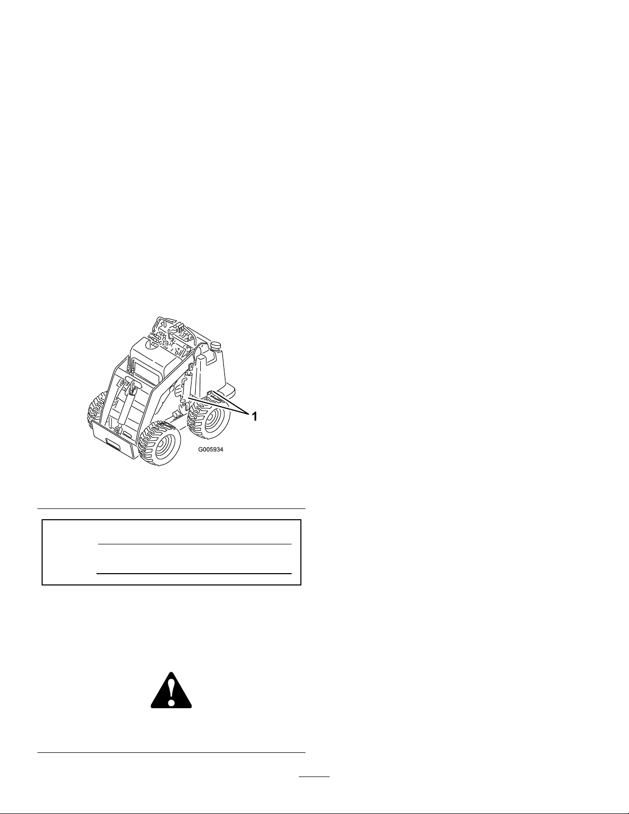
andserialnumbersofyourproductready .Figure1
identiesthelocationofthemodelandserialnumbers
ontheproduct.Writethenumbersinthespace
provided.
Figure1
1.Modelandserialnumberlocation
ModelNo.
SerialNo.
Thismanualidentiespotentialhazardsandhas
safetymessagesidentiedbythesafetyalertsymbol
(Figure2),whichsignalsahazardthatmaycauseserious
injuryordeathifyoudonotfollowtherecommended
precautions.
Figure2
1.Safetyalertsymbol
Contents
Introduction.................................................................2
Safety...........................................................................3
SafeOperatingPractices.......................................3
SoundPressure.....................................................6
SoundPower........................................................6
Vibration..............................................................6
SlopeChart..........................................................7
SafetyandInstructionalDecals.............................8
Setup..........................................................................11
1InstallingtheValveLever.................................11
2CheckingFluidLevels......................................11
3ActivatingtheBattery......................................11
ProductOverview......................................................14
Controls.............................................................14
Specications.....................................................17
Attachments/Accessories...................................17
StabilityData......................................................18
Operation...................................................................19
FillingtheFuelTank...........................................19
DrainingWaterfromtheFuelFilter.....................19
CheckingtheEngineOilLevel............................20
CheckingtheEngineCoolantLevel....................20
RemovingDebrisfromtheTraction
Unit................................................................21
CheckingtheHydraulicFluidLevel.....................21
TestingtheParkingBrake...................................21
CheckingtheTirePressure.................................22
StartingtheEngine.............................................22
DrivingtheTractionUnit...................................22
StoppingtheTractionUnit/Engine....................22
MovingaNon-functioningTraction
Unit................................................................23
UsingtheCylinderLocks....................................23
UsingAttachments.............................................24
SecuringtheTractionUnitforTransport.............25
AdjustingtheThighSupport...............................25
Maintenance...............................................................27
RecommendedMaintenanceSchedule(s)................27
PremaintenanceProcedures....................................28
OpeningtheAccessCovers................................28
Lubrication.............................................................29
GreasingtheTractionUnit.................................29
EngineMaintenance...............................................29
ServicingtheAirCleaner....................................29
ServicingtheEngineOil.....................................30
©2008—TheToro®Company
8111LyndaleAvenueSouth
Bloomington,MN55420
Contactusatwww.Toro.com.
2
PrintedintheUSA.
AllRightsReserved
Page 3
FuelSystemMaintenance.......................................31
ChangingtheFuelFilter.....................................31
BleedingtheFuelSystem....................................31
DrainingtheFuelTanks.....................................32
ElectricalSystemMaintenance................................33
ServicingtheBattery...........................................33
HydraulicSystemMaintenance...............................35
ReplacingtheHydraulicFilter.............................35
ChangingtheHydraulicFluid.............................35
CheckingtheHydraulicLines.............................35
Storage.......................................................................36
Troubleshooting.........................................................37
Schematics.................................................................40
Safety
Improperuseormaintenancebytheoperatoror
ownercanresultininjury.T oreducethepotential
forinjury,complywiththesesafetyinstructions
andalwayspayattentiontothesafetyalert
symbol
Danger
complywiththeinstructionmayresultinpersonal
injuryordeath.
,whichmeans:
—personalsafetyinstruction.Failureto
SafeOperatingPractices
Thisproductiscapableofamputatinghandsandfeet.
Alwaysfollowallsafetyinstructionstoavoidserious
injuryordeath.
Engineexhaustcontainscarbonmonoxide,an
odorless,deadlypoisonthatcankillyou.
Caution
,
W ar ning
,or
Donotruntheengineindoorsorinanenclosed
area.
Training
•ReadtheOperator’sManualandothertraining
material.Iftheoperator(s)ormechanic(s)can
notreadEnglish,itistheowner’sresponsibilityto
explainthismaterialtothem.
•Becomefamiliarwiththesafeoperationofthe
equipment,operatorcontrols,andsafetysigns.
•Alloperatorsandmechanicsshouldbetrained.The
ownerisresponsiblefortrainingtheusers.
•Neverletchildrenoruntrainedpeopleoperateor
servicetheequipment.Localregulationsmayrestrict
theageoftheoperator.
•Theowner/usercanpreventandisresponsiblefor
accidentsorinjuriesoccurringtohimselforherself,
otherpeopleorproperty.
Preparation
•Evaluatetheterraintodeterminewhataccessories
andattachmentsareneededtoproperlyand
safelyperformthejob.Onlyuseaccessoriesand
attachmentsapprovedbythemanufacturer.
•Wearappropriateclothingincludinghardhat,
safetyglasses,longpants,safetyshoes,andhearing
protection.Longhair,looseclothingorjewelrymay
gettangledinmovingparts.
3
Page 4

•Inspecttheareawheretheequipmentistobeused
andremoveallobjectssuchasrocks,toys,andwire
whichcanbethrownbythemachine.
•Useextracarewhenhandlingfuels.Theyare
ammableandvaporsareexplosive.
–Useonlyanapprovedcontainer
–Neverremovethefuelcaporaddfuelwiththe
enginerunning.Allowtheenginetocoolbefore
refueling.Donotsmoke.
–Neverrefuelordrainthemachineindoors.
•Checkthattheoperator’spresencecontrols,safety
switches,andshieldsareattachedandfunctioning
properly.Donotoperateunlesstheyarefunctioning
properly.
Operation
•Neverrunanengineinanenclosedarea.
•Onlyoperateingoodlight,keepingawayfromholes
andhiddenhazards.
•Besurealldrivesareinneutralandparkingbrakeis
engagedbeforestartingtheengine.Onlystartthe
enginefromtheoperator’sposition.
•Slowdownanduseextracareonhillsides.Besure
totravelintherecommendeddirectiononhillsides.
Turfconditionscanaffectthemachine’sstability.
•Slowdownandusecautionwhenmakingturnsand
whenchangingdirectionsonslopes.
•Neveroperatewiththeguardsnotsecurelyinplace.
Besureallinterlocksareattached,adjustedproperly,
andfunctioningproperty.
•Donotchangetheenginegovernorsettingor
overspeedtheengine.
•Stoponlevelground,lowerimplements,disengage
theauxiliaryhydraulics,engageparkingbrake,shut
offtheenginebeforeleavingtheoperator’ sposition
foranyreason.
•Keephandsandfeetawayfrommovingattachments.
•Lookbehindanddownbeforebackinguptobesure
ofaclearpath.
•Nevercarrypassengersandkeeppetsandbystanders
away.
•Slowdownandusecautionwhenmakingturnsand
crossingroadsandsidewalks.
•Donotoperatethemachineundertheinuenceof
alcoholordrugs.
•Usecarewhenloadingorunloadingthemachine
intoatrailerortruck.
•Usecarewhenapproachingblindcorners,shrubs,
trees,orotherobjectsthatmayobscurevision.
•Readallattachmentmanuals.
•Ensurethattheareaisclearofotherpeoplebefore
operatingthetractionunit.Stopthetractionunit
ifanyoneentersthearea.
•Neverleavearunningtractionunitunattended.
Alwayslowertheloaderarms,stoptheengine,set
theparkingbrake,andremovethekeybeforeleaving.
•Donotexceedtheratedoperatingcapacity,asthe
tractionunitmaybecomeunstablewhichmayresult
inlossofcontrol.
•Donotcarryaloadwiththearmsraised.Always
carryloadsclosetotheground.
•Donotoverloadtheattachmentandalwayskeep
theloadlevelwhenraisingtheloaderarms.Logs,
boards,andotheritemscouldrolldowntheloader
arms,injuringyou.
•Neverjerkthecontrols;useasteadymotion.
•Watchfortrafcwhenoperatingnearorcrossing
roadways.
•Donottouchpartswhichmaybehotfrom
operation.Allowthemtocoolbeforeattemptingto
maintain,adjust,orservice.
•Checkforoverheadclearances(i.e.branches,
doorways,electricalwires)beforedrivingunderany
objectsanddonotcontactthem.
•Ensurethatyouoperatethetractionunitinareas
wheretherearenoobstaclesincloseproximitytothe
operator.Failuretomaintainadequatedistancefrom
trees,walls,andotherbarriersmayresultininjury
asthetractionunitbacksupduringoperationifthe
operatorisnotattentivetothesurroundings.Only
operatetheunitinareaswherethereissufcient
clearancefortheoperatortosafelymaneuverthe
product.
•Beforedigging,havetheareamarkedfor
undergroundutilities,anddonotdiginmarkedareas.
•Locatethepinchpointareasmarkedonthetraction
unitandattachmentsandkeephandsandfeetaway
fromtheseareas.
•Beforeoperatingthetractionunitwithan
attachment,ensurethattheattachmentisproperly
installed.
•Donotplaceyourfeetundertheplatform.
SlopeOperation
Slopesareamajorfactorrelatedtoloss-of-controland
tip-overaccidents,whichcanresultinsevereinjuryor
death.Allslopesrequireextracaution.
•Donotoperatethetractionunitonhillsidesor
slopesexceedingtheanglesrecommendedinthe
4
Page 5

StabilityDatasectioninSpecications,page17,and
thoseintheattachmentOperator’sManual.Seealso
theSlopeChart,page7.
•Operateupanddownslopeswiththeheavyend
ofthetractionunituphill.Weightdistribution
changes.Anemptybucketwillmaketherearof
thetractionunittheheavyend,andafullbucket
willmakethefrontofthetractionunittheheavy
end.Mostotherattachmentswillmakethefrontof
tractionunittheheavyend.
•Raisingtheloaderarmsonaslopewillaffectthe
stabilityofthemachine.Wheneverpossible,keepthe
loaderarmsintheloweredpositionwhenonslopes.
•Removinganattachmentonaslopewillmakethe
rearofthetractionunitheavy.RefertotheStability
DatasectioninSpecications,page17,todetermine
whethertheattachmentcanbesafelyremovedon
theslope.
•Removeobstaclessuchasrocks,treelimbs,etc.from
theworkarea.Watchforholes,ruts,orbumps,as
uneventerraincouldoverturnthetractionunit.Tall
grasscanhideobstacles.
•UseonlyToro-approvedattachments.Attachments
canchangethestabilityandtheoperating
characteristicsofthetractionunit.Warrantymaybe
voidedifusedwithunapprovedattachments.
•Keepallmovementsonslopesslowandgradual.Do
notmakesuddenchangesinspeedordirection.
•Avoidstartingorstoppingonaslope.Ifthetraction
unitlosestraction,proceedslowly,straightdownthe
slope.
•Avoidturningonslopes.Ifyoumustturn,turn
slowlyandkeeptheheavyendofthetractionunit
uphill.
•Donotoperateneardrop-offs,ditches,or
embankments.Thetractionunitcouldsuddenlyturn
overifawheelgoesovertheedgeofaclifforditch,
orifanedgecavesin.
•Donotoperateonwetgrass.Reducedtractioncould
causesliding.
•Donotparkthetractionunitonahillsideorslope
withoutloweringtheattachmenttothegroundand
chockingthewheels.
•Donottrytostabilizethetractionunitbyputting
yourfootontheground.
MaintenanceandStorage
•Disengagetheauxiliaryhydraulics,lowerthe
attachment,settheparkingbrake,stoptheengine,
andremovethekey.Waitforallmovementtostop
beforeadjusting,cleaning,orrepairing.
•Cleandebrisfromattachments,drives,mufers,and
enginetohelppreventres.Cleanupoilorfuel
spillage.
•Lettheenginecoolbeforestoringanddonotstore
nearame.
•Donotstorefuelnearamesordrainindoors.
•Parkthemachineonlevelground.Neverallow
untrainedpersonneltoservicethemachine.
•Usejackstandstosupportcomponentswhen
required.
•Carefullyreleasepressurefromcomponentswith
storedenergy.
•Disconnectthebatterybeforemakinganyrepairs.
Disconnectthenegativeterminalrstandthe
positivelast.Reconnectpositiverstandnegative
last.
•Keephandsandfeetawayfrommovingparts.If
possible,donotmakeadjustmentswiththeengine
running.
•Chargebatteriesinanopenwellventilatedarea,away
fromsparkandames.Unplugthechargerbefore
connectingordisconnectingitfromthebattery.
Wearprotectiveclothinganduseinsulatedtools.
•Keepallpartsingoodworkingconditionandall
hardwaretightened.Replaceallwornordamaged
decals.
•Ifanymaintenanceorrepairrequirestheloaderarms
tobeintheraisedposition,securethearmsinthe
raisedpositionwiththehydrauliccylinderlocks.
•Keepnutsandboltstight.Keepequipmentingood
condition.
•Nevertamperwithsafetydevices.
•Keepthetractionunitfreeofgrass,leaves,orother
debrisbuildup.Cleanupoilorfuelspillage.Allow
thetractionunittocoolbeforestoring.
•Useextracarewhenhandlingfuels.Theyare
ammableandvaporsareexplosive.
–Useonlyanapprovedcontainer.
–Neverremovethefuelcaporaddfuelwhen
theengineisrunning.Allowtheenginetocool
beforerefueling.Donotsmoke.
–Neverrefuelthetractionunitindoors.
–Neverstorethetractionunitorfuelcontainer
insidewherethereisanopename,suchasnear
awaterheaterorfurnace.
–Neverllacontainerwhileitisinsideavehicle,
trunk,pickupbed,oranysurfaceotherthanthe
ground.
5
Page 6

–Keepcontainernozzleincontactwiththetank
duringlling.
•Stopandinspecttheequipmentifyoustrikean
object.Makeanynecessaryrepairsbeforerestarting.
•UseonlygenuineTororeplacementpartstoensure
thatoriginalstandardsaremaintained.
•Batteryacidispoisonousandcancauseburns.Avoid
contactwithskin,eyes,andclothing.Protectyour
face,eyes,andclothingwhenworkingwithabattery.
•Batterygasescanexplode.Keepcigarettes,sparks
andamesawayfromthebattery.
•Keepyourbodyandhandsawayfrompinhole
leaksornozzlesthatejecthighpressurehydraulic
uid.Usecardboardorpapertondhydraulic
leaks;neveruseyourhands.Hydraulicuidescaping
underpressurecanpenetrateskinandcauseinjury
requiringsurgerywithinafewhoursbyaqualied
surgeonorgangrenemayresult.
SoundPressure
Thisunithasamaximumsoundpressurelevelatthe
operator’searof97dBA,basedonmeasurementsof
identicalmachinesperEN11201.
SoundPower
Thisunithasaguaranteedsoundpowerlevelof101
dBA,basedonmeasurementsofidenticalmachinesper
EN6395.
Vibration
Thisunitdoesnotexceedahand/armvibrationlevelof
0.5m/s
perEN1033.
Thisunitdoesnotexceedawholebodyvibration
levelof0.1m/s
machinesperEN1032.
2
,basedonmeasurementsofidenticalmachines
2
,basedonmeasurementsofidentical
6
Page 7

SlopeChart7SafetyandInstructionalDecals
Page 8
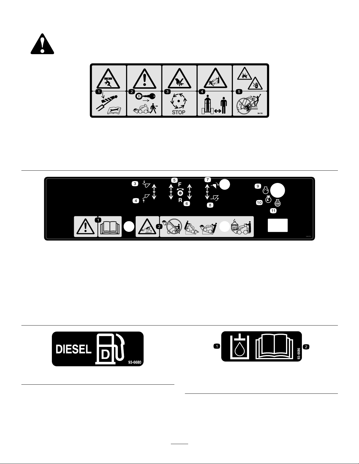
Safetydecalsandinstructionsareeasilyvisibletotheoperatorandarelocatednearanyareaof
potentialdanger.Replaceanydecalthatisdamagedorlost.
100-1701
1.Crushinghazard—installthecylinderlockandreadtheinstructionsbeforeservicingorperformingmaintenance.
2.Warning—removetheignitionkeyandlowertheloaderarmsbeforeleavingthemachine.
3.Cuttinghazardofhand—waitformovingpartstostop.
4.Crushing/dismembermenthazardofbystanders—keepbystandersasafedistancefromthemachine.
5.Explosionandelectricalshockhazards—donotdiginareaswithburiedgasorelectricallines.
1.Warning—readthe
Operator’sManual.
2.Tippinghazard—donot
stepoffoperatorplatform
withloadraised,always
operatewiththeheavyend
ofthemachinepointed
uphill,carryloadslow,
maximumloadis515lbs
(234kg).
3.Armlift–down
4.Armlift—up
5.Wheeldrive—forward
6.Wheeldrive—reverse9.Engine—start
93-6680
108-9733
7.Buckettilt—down10.Engine—run
8.Buckettilt—up11.Engine—stop
93-6686
1.Hydraulicoil
2.ReadtheOperator’sManual.
8
Page 9
100-1702
1.Warning—readtheOperator’sManual;maximumload
ratingof515lb.(234Kg).
100-1703
1.Speedselector
1.Fast
2.Tractiondrive
98-8235
3.Slow
100-1704
1.ReadtheOperator’s
Manual.
2.Placetheauxiliary
hydraulicsinNeutral.
3.Starttheengine.
93-7814
1.Entanglementhazard,belt—stayawayfrommovingparts.
100-8821
1.Crushinghazardandcuttinghazardofhand—stayasafe
distancefromthefrontofthetractionunitwhentheloader
armsareraised.
98-8219
1.Fast
2.Throttle
100-1692
1.Brakeengaged3.Brakedisengaged
2.Parkingbrake
93-9084
1.Liftpoint
3.Slow
2.Tie-downpoint
1.Warning—donotcarrypassengers.
100-8822
9
Page 10
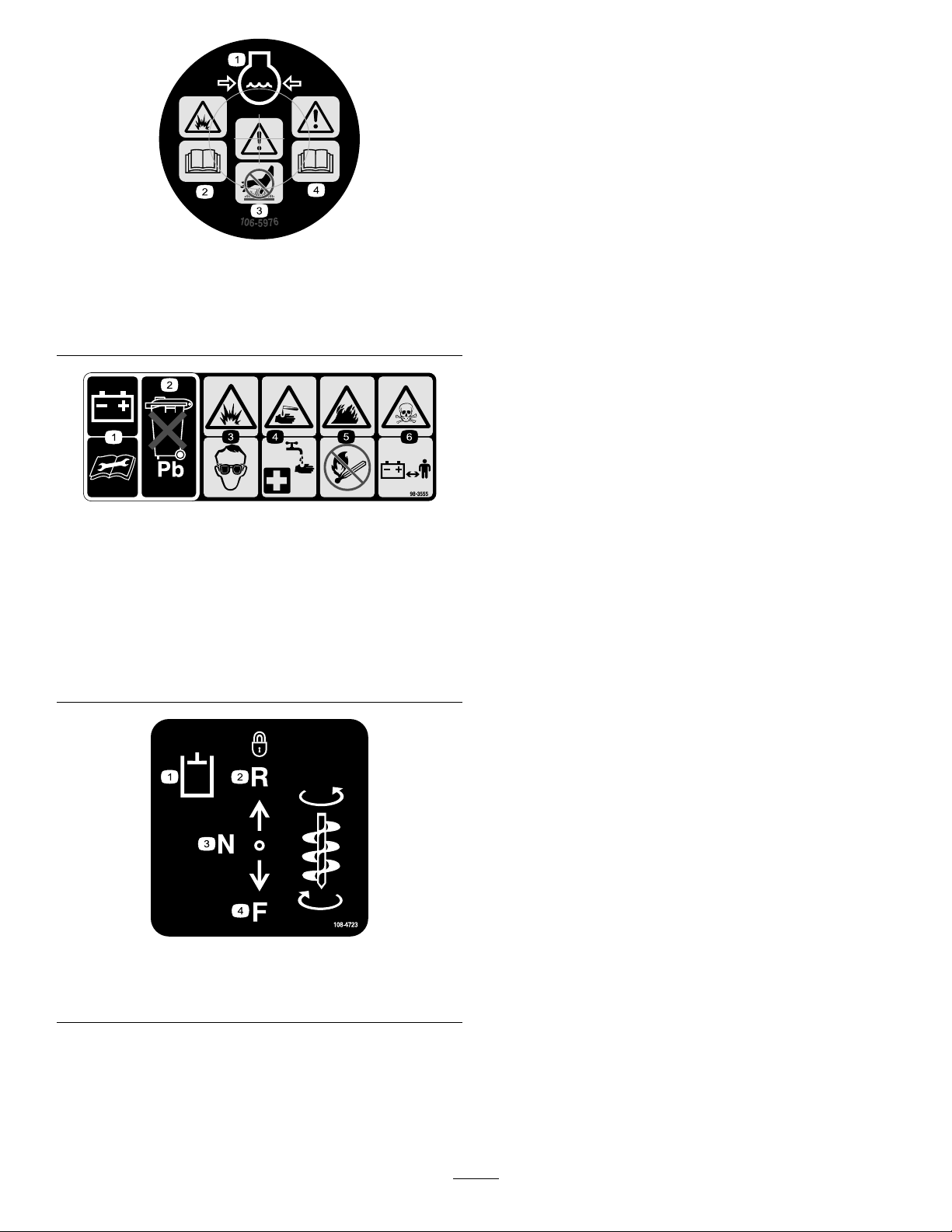
106-5976
1.Enginecoolantunder
pressure
2.Explosionhazard—read
theOperator’sManual.
3.Warning—donottouch
thehotsurface.
4.Warning—readthe
Operator’sManual.
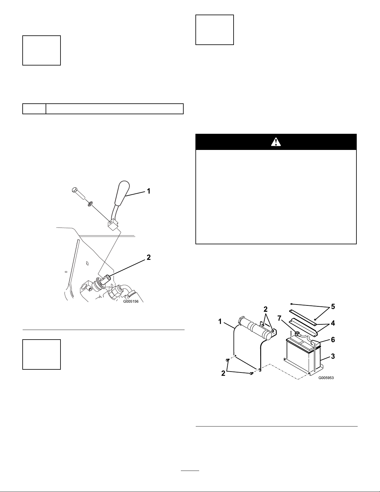
98-3555
1.Readtheinstructionsbeforeservicingorperforming
maintenanceonthebattery.
2.Containslead;donotdiscard.
3.Explosionhazard—weareyeprotection.
4.Causticliquid/chemicalburnhazard—toperformrstaid,
ushwithwater.
5.Firehazard—nore,openames,orsmoking.
6.Poisonhazard—keepchildrenasafedistancefromthe
battery.
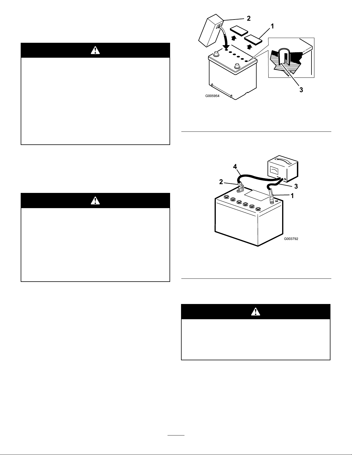
1.Auxiliaryhydraulics
2.Lockedreverse(detent)
108-4723
3.Neutral(off)
4.Forward
10
Page 11
Setup
3
1
InstallingtheValveLever
Partsneededforthisprocedure:
1
Speedselectorvalvelever
Procedure
1.Removeanddiscardthenutsecuringtheboltand
lockwashertothespeedselectorlever.
2.Securethelevertothespeedselectorvalveusingthe
boltandlockwasherasillustratedinFigure3.
ActivatingtheBattery
NoPartsRequired
Procedure
Thetractionunitisshippedwithadrybattery.Youmust
purchasebulkelectrolytewith1.260specicgravity
fromalocalbatterysupplyoutlet.
Batteryterminalsormetaltoolscouldshort
againstmetalcomponents,causingsparks.
Sparkscancausethebatterygassestoexplode,
resultinginpersonalinjury.
•Whenremovingorinstallingthebattery,do
notallowthebatteryterminalstotouchany
metalpartsofthetractionunit.
•Donotallowmetaltoolstoshortbetween
thebatteryterminalsandmetalpartsofthe
tractionunit.
Figure3
1.Speedselectorvalvelever2.Speedselectorvalve
2
CheckingFluidLevels
NoPartsRequired
Procedure
Beforestartingtheengineforthersttime,checkthe
engineoil,hydraulicuid,andenginecoolantlevels.
RefertoOperationformoreinformation.
1.Parkthetractionunitonalevelsurface,raisethe
loaderarms,andinstallthecylinderlocks.
2.Stoptheengineandremovethekey.
3.Removethefourboltssecuringthebatterycover
andremovethecover(Figure4).
Figure4
1.Batterycover5.Nut
2.Bolt6.Positivecable
3.Battery7.Negativecable
4.Bars
4.Removethenutsandbarssecuringthebattery
(Figure4).
11
Page 12
5.Disconnectthenegative(black)cablefrom
1
2
3
4
G003792
thenegative(-)batterypost,ifitisn’talready
disconnected(Figure4).
Incorrectbatterycableroutingcoulddamage
thetractorandcablescausingsparks.Sparks
cancausethebatterygassestoexplode,
resultinginpersonalinjury.
•Alwaysdisconnectthenegative(black)
batterycablebeforedisconnectingthe
positive(red)cable.
•Alwaysconnectthepositive(red)battery
cablebeforeconnectingthenegative(black)
cable.
6.Disconnectthepositive(red)cablefromthepositive
(+)batterypost(Figure4).
7.Liftthebatteryoffoftheplatform.
8.Removethellercapsfromthebattery.
Figure5
1.Fillercaps
2.Electrolyte
3.Lowerpartofthetube
10.Leavethecoversoffandconnecta3to4amp
batterychargertothebatteryposts(Figure6).
Batteryelectrolytecontainssulfuricacidwhich
isadeadlypoisonandcausessevereburns.
•Donotdrinkelectrolyteandavoidcontact
withskin,eyesorclothing.Wearsafety
glassestoshieldyoureyesandrobbergloves
toprotectyourhands.
•Fillthebatterywherecleanwaterisalways
availableforushingtheskin.
9.Slowlypourelectrolyteintoeachcelluntilthe
electrolytelevelisuptothelowerpartofthetube
(Figure5).
Figure6
1.Positivepost
2.Negativepost
3.Chargerred(+)wire
4.Chargerblack(—)wire
11.Chargethebatteryatarateof4amperesorlessfor
4hours(12volts).
Chargingthebatteryproducesgassesthatcan
explode.
Neversmokenearthebatteryandkeepsparks
andamesawayfrombattery.
12.Whenthebatteryisfullycharged,unplugthecharger
fromtheelectricaloutlet,thendisconnectthe
chargerleadsfromthebatteryposts(Figure6).
13.Slowlypourelectrolyteintoeachcelluntilthelevelis
onceagainuptotheupperlineonthebatterycase
(Figure5)andinstallthecovers.
14.Installthebatteryontotheplatform(Figure4).
12
Page 13

15.Securethebatteryinthechassiswiththebarsand
nutsremovedpreviously(Figure4).
16.Connectthepositive(red)cabletothepositive(+)
batterypost(Figure4).Slidetherubbercoverover
thebatterypost.
17.Connectthenegative(black)cabletothenegative
(-)batterypost(Figure4).
Important:Ensurethatthebatterycablesdo
notcontactanysharpedgesoreachother.
18.Installthebatterycover(Figure4).
13
Page 14

ProductOverview
G005939
1
2
3
4
5
20
17
6
18
7
8
13
14
15
12
11
21
9
18
16
4
14
19
10
22
G006057
631524
78
Figure7
1.Mountplate7.Wheel
2.Tiltcylinder
3.Auxiliaryhydrauliccouplers
4.Loaderarms
5.Frontaccesscover11.Engine17.Indicatorlights
6.Fueltank
8.Liftcylinder14.Liftpoints20.Radiatorllcap
9.Operatorplatform
10.Rearaccesscover(open)
12.Airlter
13.Controlpanel
15.Handle21.Thighsupport
16.Battery22.Flowdividercontrol
18.Towvalves
19.Parkingbrakelever
Controls
Becomefamiliarwithallthecontrols(Figure8)before
youstarttheengineandoperatethetractionunit.
1.Tractioncontrollevers
2.Attachmenttiltlever6.Throttlelever
3.Loaderarmlever7.Keyswitch
4.Auxiliaryhydraulicslever8.Hourmeter
KeySwitch
Thekeyswitch,usedtostartandstoptheengine,has
threepositions:off,run,andstart.
Figure8
5.Speedselectorlever
•Tostarttheengine,rotatethekeytotherunposition,
theglowpluglightwillcomeon.Whentheglow
pluglightturnsoff,turnthekeytothestartposition.
Releasethekeywhenenginestartsanditwillmove
automaticallytotherunposition.
•Tostoptheengine,rotatethekeytotheoffposition.
ThrottleLever
Movethecontrolforwardtoincreasetheenginespeed
andrearwardtodecreasespeed.
TractionControlLevers
•Tomoveforward,movethetractioncontrollevers
forward.Tomoverearward,movethetraction
controlleversrearward.
•Togostraight,movebothtractioncontrollevers
equally.
•Toturn,movetheleverlocatedonthesideyou
wanttoturnbacktowardtheneutralpositionwhile
keepingtheotherleverengaged.
14
Page 15

Note:Thefartheryoumovethetractioncontrol
leversineitherdirection,thefasterthetractionunit
willmoveinthatdirection.
•Tosloworstop,movethetractioncontrollevers
toneutral.
AttachmentTiltLever
•Totilttheattachmentforward,slowlypushthe
attachmenttiltleverforward.
AuxiliaryHydraulicsLever
•Tooperateahydraulicattachmentinforward
direction,slowlypulltheauxiliaryhydraulicslever
upwardandthenrearward.
•Tooperateahydraulicattachmentinreverse
direction,slowlypulltheauxiliaryhydraulicslever
upwardandthenpushitforward.Thisisalsocalled
thedetentpositionbecauseitdoesnotrequire
operatorpresence.
•Totilttheattachmentrearward,slowlypullthe
attachmenttiltleverrearward.
LoaderArmLever
•Tolowertheloaderarms,slowlypushtheloader
armleverforward.
•Toraisetheloaderarms,slowlypulltheloaderarm
leverrearward.
LoaderValveLock
Theloadervalvelocksecurestheloaderarmand
attachmenttiltleverssothatyoucannotpushthem
forward.Thishelpstoensurethatnoonewill
accidentallylowertheloaderarmsduringmaintenance.
Securetheloaderarmswiththelockanytimeyouneed
tostopthemachinewiththeloaderarmsraised.
Tosetthelock,pullitbackandallthewaydownagainst
thelevers(Fig.13).
Note:Youwillneedtomovetheleversrearwardto
engageordisengagetheloadervalvelock.
SpeedSelectorLever
Ifyoumovethespeedselectorleverwhilethe
tractionunitisinmotion,thetractionunitwill
eitherstopsuddenlyoracceleratequickly.If
youoperatethetractionunitwiththespeed
selectorleverinanintermediateposition,the
tractionunitwilloperateerraticallyandmaybe
damaged.Y oucouldlosecontrolofthetraction
unitandinjurebystandersoryourself.
•Donotmovethespeedselectorleverwhen
thetractionunitisinmotion.
•Donotoperatethetractionunitwhen
thespeedselectorisinanyintermediate
position(i.e.,anypositionotherthanfully
forwardorfullyrearward).
•Movethespeedselectorlevertotheforwardposition
tosetthetractiondrive,loaderarms,andattachment
tilttohighspeedandtheauxiliaryhydraulicstolow
speed.
•Movethespeedselectorlevertotherearward
positiontosettheauxiliaryhydraulicstohighspeed
andthetractiondrive,loaderarms,andattachment
tilttolowspeed.
1.Loadervalvelock,
engaged
Figure9
2.Loadervalvelock,
disengaged
HourMeter
Thehourmeterdisplaysthenumberofhoursof
operationthathavebeenloggedonthetractionunit.
After50hoursandevery75hoursthereafter(thatisat
50,125,200,etc.)thehourmeterdisplaysSVConthe
lowerleftsideofthescreentoremindyoutochangethe
oilandperformtherequiredmaintenance.Afterevery
400hours(400,800,1200,etc.),thehourmeterdisplays
SVConthelowerrightsideofthescreentoremind
youtoperformthemaintenanceproceduresbasedona
400hourschedule.Thesereminderscomeonstarting
threehourspriortotheserviceintervaltimeandashat
regularintervalsforsixhours.
15
Page 16

FlowDividerControl
ParkingBrake
Thetractionunithydraulics(i.e.,thetractiondrive,
loaderarms,andattachmenttilt)workonaseparate
hydrauliccircuitfromtheauxiliaryhydraulicsfor
poweringattachments;however,thetwosystemsshare
thesamehydraulicpumps.Usingtheowdivider
control(Figure10),youcanvarythespeedofthe
tractionunithydraulicsbydivertinghydraulicowtothe
auxiliaryhydraulicscircuit.Theowdividerallowsyou
todividetheowofuidinvaryingdegreestoslowthe
tractionunit.Thus,themorehydraulicowyoudivert
totheauxiliaryhydraulics,theslowerthetractionunit
hydraulicswillmove.
Figure10
1.Flowdividercontrol4.10to11o’clockposition
2.Knob5.9o’clockposition
3.12o’clockposition
•Movetheowdividercontroltothetwelveo’clock
positiontoprovidemaximumspeedtothetraction
unithydraulics.
Thetractionunitisequippedwithaparkingbrake
(Figure11).Rotatethebrakeleverdownwardtosetthe
braketolocktherearwheelswheneverthetractionunit
willbestoppedonahillorleftunattended.Movethe
leverupbeforedrivingthetractionunit.
Figure11
1.Parkingbrakelever—On
position
2.Parkingbrakelever—Off
position
IndicatorLights
Theindicatorlightswarnyouinthecaseofasystem
malfunctionand,inthecaseoftheglowpluglight,
indicatethattheglowplugsareon.Figure12illustrates
thefourindicatorlights.
Usethissettingforfastoperationofthetractionunit.
•Movetheowdividercontrolbetweenthetwelve
o’clockandnineo’clockpositionstoslowthe
tractionunithydraulicsandnetunethespeed.
Useasettinginthisrangewithattachments
withhydraulicswhereyouneedtobothrunthe
attachmentandmovethetractionunithydraulics,
suchastheauger,boringunit,hydraulicblade,and
tiller.
•Movethecontroltothenineo’clockpositionto
transferallhydraulicowtotheauxiliaryhydraulics
oftheattachment.
Inthissetting,thetractionunithydraulicswillnot
work.Usethissettingwithhydraulicattachments
thatdonotrequiredthetractionunithydraulics.
Therearecurrentlynoattachmentsthatrequirethe
nineo’clockposition;however,thetrencherdoes
workbestifyousetitclosetonineo’clocksothat
thetractionunitwillcreepslowlywhentrenching.
Note:Theowdividercontrolcanbexedinplace
byturningtheknobonthecontrolclockwiseuntilit
contactsthedial(Figure10).
Figure12
1.Oilpressurelight
2.Batterylight
3.Enginetemperaturelight
4.Glowpluglight
•EngineTemperatureLight
Iftheenginetemperaturelightison,theengineis
overheating.Stoptheengineandallowthetraction
unittocooldown.Checkthecoolantlevelandthe
beltstothefanandwaterpump.Fillthecoolantas
requiredandreplaceanywornorslippingbelts.If
theproblempersists,contactyourAuthorizedToro
Dealerfordiagnosticsandrepair.
•OilPressureLight
Thislightisonforafewsecondswheneveryou
starttheengine.Iftheoilpressurelightisonwhile
theengineisrunning,theengineoilpressureislow .
Stoptheengineandallowthetractionunittocool
down.Checktheoillevelandllthecrankcasewith
16
Page 17

oilasneeded.Iftheproblempersists,contactyour
AuthorizedToroDealerfordiagnosticsandrepair.
•BatteryLight
Thislightisonforafewsecondswheneveryoustart
theengine.Ifthebatterylightisonwhiletheengine
isrunning,thealternator,battery,orelectricalsystem
Thislightisonwhenthekeyisturnedtorunbefore
startingtheengine.Theglowpluglightwillremain
onforupto10seconds,indicatingthattheglow
plugsarewarmingtheengine.Iftheglowpluglight
isonwhiletheengineisrunning,theglowplugsare
broken.ContactyourAuthorizedToroDealerfor
diagnosticsandrepair.
isbroken.ContactyourAuthorizedT oroDealerfor
diagnosticsandrepair.
•GlowPlugLight
Specications
Note:Specicationsanddesignaresubjecttochangewithoutnotice.
Width
Length
Height
Weight(withoutattachmentorcounterweight)1722lb(783kg)
Operatingcapacity(with200lboperator,thestandardbucket,andwithoutthecounterweight)524lb(238kg)
Tippingcapacity(with200lboperator,thestandardbucket,andwithoutthecounterweight)l048lb(476kg)
Wheelbase
Dumpheight(withstandardbucket)47inches(120cm)
Reach—fullyraised(withstandardbucket)26inches(66cm)
Heighttohingepin(narrowbucketinstandardposition)66inches(168cm)
40.5inches(103cm)
60inches(152cm)
49inches(125cm)
28inches(71cm)
Attachments/Accessories
AselectionofToroapprovedattachmentsandaccessoriesareavailableforusewiththemachinetoenhanceand
expanditscapabilities.ContactyourAuthorizedServiceDealerorDistributororgotowww .T oro.comforalistof
allapprovedattachmentsandaccessories.
Important:UseonlyToroapprovedattachments.Otherattachmentsmaycreateanunsafeoperating
environmentordamagethetractionunit.
17
Page 18

StabilityData
Thefollowingtableslistthemaximumsloperecommendedforthetractionunitinthepositionslistedinthetables.
Slopesoverthelisteddegreemaycausethetractionunittobecomeunstable.Thedatainthetablesassumethatthe
loaderarmsarefullylowered;raisedarmsmayaffectthestability.
Ineachattachmentmanualisasetofthreestabilityratings,oneforeachhillposition.Todeterminethemaximum
slopeyoucantraversewiththeattachmentinstalled,ndthedegreeofslopethatcorrespondstothestabilityratings
oftheattachment.Example:IftheattachmenthasaFrontUphillratingofB,aRearUphillratingofD,anda
SideUphillratingofC,thenyoucoulddriveforwardupan18°slope,rearwardupa10°slope,orsidewaysona
14°slope,aslistedinthefollowingtable.
MaximumRecommendedSlopewhen
FrontUphillRearUphill
Conguration
Tractionunitwithoutattachment
Tractionunitwithcounterweight,withoutattachment
Tractionunitwithanattachmentratedwithoneofthefollowingstabilityratings
foreachslopeposition:*
A
B
C15°16°14°
D
E
7°20°17°
5°21°17°
25°25°20°
18°19°18°
10°10°9°
5°5°5°
Operatingwith:
SideUphill
18
Page 19

Operation
Note:Determinetheleftandrightsidesofthemachinefromthenormaloperatingposition.
Important:Beforeoperating,checkthefuel,oil,andcoolantlevel;removedebrisfromthetractionunit;
testtheparkingbrake,andcheckthetirepressure.Also,ensurethattheareaisclearofpeopleanddebris.
Youshouldalsoknowandhavemarkedthelocationsofallutilitylines.
Youcouldfalloffoftheplatformandbeseriouslyinjuredduringoperation.
Donotmovethecontrolleversunlessyouarestandingwithbothfeetontheplatformandyourhands
areholdingthehandles.
FillingtheFuelTank
Theenginerunsonclean,freshdieselfuelwith
aminimumcetaneratingof40.Purchasefuelin
quantitiesthatcanbeusedwithin30daystoensure
fuelfreshness.
Usesummergradedieselfuel(No.2-D)attemperatures
above20°F(-7°C)andwintergradedieselfuel
(No.1-DorNo.1-D/2-Dblend)below20°F
(-7°C).Useofwintergradedieselfuelatlower
temperaturesprovideslowerashpointandpourpoint
characteristics,allowingeasierstartsandlesseningthe
chancesofchemicalseparationofthefuelduetolower
temperatures.
Useofsummergradedieselfuelabove20°F(-7°C)
willcontributetowardlongerlifeofthefuelpump
components.
Important:Donotusekeroseneorgasolinein
placeofdieselfuel.Failuretoobservethiscaution
willdamagetheengine.
1.Parkthetractionunitonalevelsurface,lowerthe
loaderarms,andstoptheengine.
2.Removethekeyandallowtheenginetocool.
3.Cleanaroundthefueltankcapandremovethecap.
4.Fillthetanktoaboutoneinchbelowthetopofthe
tank,notthellerneck,withdieselfuel.
Undercertainconditions,dieselfuelandfuel
vaporsarehighlyammableandexplosive.A
reorexplosionfromfuelcanburnyouand
othersandcancausepropertydamage.
•Useafunnelandllthefueltankoutdoors,
inanopenarea,whentheengineisoffand
iscold.Wipeupanyfuelthatspills.
•Donotllthefueltankcompletelyfull.Add
fueltothefueltankuntilthelevelis1/4to
1/2inch(6to13mm)belowthebottomof
thellerneck.Thisemptyspaceinthetank
allowsthefueltoexpand.
•Neversmokewhenhandlingfuel,andstay
awayfromanopenameorwherefuel
fumesmaybeignitedbyaspark.
•Storefuelinaclean,safety-approved
containerandkeepthecapinplace.
5.Installthefueltankcap.Wipeupanyfuelthatmay
havespilled.
Note:Ifpossible,llthefueltankaftereachuse.This
willminimizepossiblebuildupofcondensationinside
thefueltank.
DrainingWaterfromtheFuel
Filter
ServiceInterval:Beforeeachuseordaily
Drainwaterorothercontaminantsfromthefuellter
daily.
1.Stoptheengineandremovethekey.
2.Opentherearaccesscover.
19
Page 20

3.Turnthedrainvalveuntilthewaterrunsoutofthe
G005936
4
123
lter(Figure13).
Note:Thefuellterislocatednearthebottom
ofthefueltank.
9.Slowlypouronlyenoughoil(dieselengineoil,API
serviceCH-4,CI-4,orhigher;refertoServicingthe
EngineOilinMaintenance)intothevalvecoverto
raisetheleveltotheuppermarkonthedipstick.
Important:Donotoverllthecrankcasewith
oilbecausetheenginemaybedamaged.
10.Replacethellercapanddipstick.
CheckingtheEngineCoolant
Level
ServiceInterval:Beforeeachuseordaily
Figure13
1.Fuellter
2.Drainvalve
4.Closethevalve.
5.Closetherearaccesscover.
CheckingtheEngineOilLevel
ServiceInterval:Beforeeachuseordaily
1.Parkthetractionunitonalevelsurface,lowerthe
loaderarms,andstoptheengine.
2.Removethekeyandallowtheenginetocool.
3.Opentherearaccesscover.
4.Cleanaroundtheoildipstick(Figure14).
Thecoolingsystemislledwitha50/50solutionof
waterandpermanentethyleneglycolantifreeze.Check
thelevelofcoolantatthebeginningofeachday,before
startingtheengine.
Iftheenginehasbeenrunning,thecoolant
intheradiatorwillbehotandpressurized.If
youremovethecap,itmaysprayout,causing
severeburns.
•Donotremovetheradiatorcaptocheck
coolantlevels.
•Donotremovetheradiatorcapwhenthe
engineishot.Allowtheenginetocoolforat
least15minutesoruntiltheradiatorcapis
coolenoughtotouchwithoutburningyour
hand.
1.Parkthetractionunitonalevelsurface,lowerthe
loaderarms,andstoptheengine.
Figure14
1.Fillercap
2.Valvecover4.Metalend
3.Oildipstick
5.Pulloutthedipstickandwipethemetalendclean
(Figure14).
6.Slidethedipstickfullyintothedipsticktube
(Figure14).
7.Pullthedipstickoutandlookatthemetalend.
8.Iftheoillevelislow ,cleanaroundtheoilllercap
andremovethecap(Figure14).
2.Removethekeyandallowtheenginetocool.
3.Removetheradiatorllercapandcheckthecoolant
level(Figure15).
Thecoolantshouldbeuptollerneck.
Figure15
1.Radiatorcap
4.Ifcoolantlevelislow ,addcoolantuptothebottom
ofthellerneck.
20
Page 21

Important:Donotoverlltheradiator.
4.Removethefrontaccesscover.
5.Replacetheradiatorllercap,ensuringthatitis
tightlysealed.
RemovingDebrisfromthe
TractionUnit
ServiceInterval:Beforeeachuseordaily
Important:Operatingtheenginewithablocked
radiator,willresultinenginedamagefrom
overheating.
1.Parkthetractionunitonalevelsurface,raisethe
loaderarms,andinstallthecylinderlocks.
2.Stoptheengineandremovethekey.
3.Removethefrontaccesscover.
4.Cleananydebrisfromthegrill.
5.Opentherearaccesscover.
6.Wipeawaydebrisfromtheaircleaner.
7.Cleananydebrisbuildupontheenginewithabrush
orblowerbeforeeachuse.
Important:Itispreferabletoblowdirtout,
ratherthanwashingitout.Ifwaterisused,
keepitawayfromelectricalitemsandhydraulic
valves.Donotuseahigh-pressurewasher.
High-pressurewashingcandamagethe
electricalsystemandhydraulicvalvesordeplete
grease.
8.Replaceandsecurethefrontandrearaccesscovers.
9.Removeandstorethecylinderlocksandlowerthe
loaderarms.
5.Cleantheareaaroundthellerneckofthehydraulic
tank(Figure16).
6.Removethecapfromthellerneckandcheckthe
uidlevelonthedipstick(Figure16).
Theuidlevelshouldbebetweenthemarksonthe
dipstick.
Figure16
1.Fillerneckcap2.Dipstick
7.Ifthelevelislow,addenoughuidtoraiseittothe
properlevel.
8.Installthecaponthellerneck.
9.Installthefrontaccesscover.
10.Removeandstorethecylinderlocksandlowerthe
loaderarms.
TestingtheParkingBrake
ServiceInterval:Beforeeachuseordaily
1.MovetheparkingbrakelevertotheOnposition
(Figure17).
CheckingtheHydraulicFluid
Level
ServiceInterval:Every25hours
Checkthehydraulicuidlevelbeforetheengineisrst
startedandafterevery25operatinghours.
HydraulicT ankCapacity:17.25USgallons(67l)
Use10W -30or15W-40detergent,dieselengineoil(API
serviceCH-4orhigher).
1.Removetheattachment,ifoneisinstalled.
2.Parkthetractionunitonalevelsurface,raisethe
loaderarms,andinstallthecylinderlocks.
3.Stoptheengine,removethekey ,andallowthe
enginetocool.
Figure17
1.Parkingbrakelever—On
position
2.Starttheengine.
3.Slowlyeasethetractiondriveleversforwardor
rearward.
4.Ifthetractionunitmoves,contactyourAuthorized
ToroDealerforservice.
21
2.Parkingbrakelever—Off
position
Page 22

CheckingtheTirePressure
1
G003793
ServiceInterval:Beforeeachuseordaily
Maintaintheairpressureinthetiresasspecied.Check
thetireswhentheyarecoldtogetthemostaccurate
reading.
Pressure:15-20psi(103-138kPa)
Note:Usealowertirepressure,15psi(103kPa),when
operatinginsandysoilconditionstoprovidebetter
tractionintheloosesoil.
freezingorlower),hydraulicsystemdamage
couldoccur.Whenstartingtheenginein
coldconditions,allowtheenginetorunin
themiddlethrottlepositionfor2to5minutes
beforemovingthethrottletofast(rabbit).
Note:Ifoutdoortemperatureisbelowfreezing,
storethetractionunitinagaragetokeepitwarmer
andaidinstarting.
DrivingtheTractionUnit
Thethrottlecontrolregulatestheenginespeedas
measuredinrpm(revolutionsperminute).Placethe
throttleleverinthefast(rabbit)positionforbest
performance.
Note:Thethrottlepositioncanbeutilizedtooperate
atslowerspeeds.
Todrivethetractionunit,completethefollowing
actionsasnecessary:
Figure18
1.Valvestem
StartingtheEngine
1.Standontheplatform.
2.Ensurethattheauxiliaryhydraulicsleverisin
neutral.
3.Movethethrottlelevermidwaybetweenslow
(turtle)andfast(rabbit)positions.
4.Insertthekeyintotheignitionandturnittothe
runposition.
Note:Thebattery,oilpressure,andglowplug
lightswillcomeon.
5.Whentheglowpluglightturnsoff,turnthekeyto
thestartposition.Whentheenginesstarts,release
thekey .
Note:Awarmenginemaybestartedwithout
waitingforthelighttoturnoff.
Important:Donotengagethestarterformore
than10secondsatatime.Iftheenginefails
tostart,allowa30secondcool-downperiod
betweenattempts.Failuretofollowthese
instructionscanburnoutthestartermotor.
6.Movethethrottlelevertodesiredsetting.
Important:Ifyouruntheengineathigh
speedswhenthehydraulicsystemiscold(i.e.,
whentheambientairtemperatureisnear
•Tomoveforward,movethetractioncontrollevers
forward.
•Tomoverearward,movethetractioncontrollevers
rearward.
•Togostraight,movebothtractioncontrollevers
equally.
•Toturn,movetheleverlocatedonthesideyou
wanttoturntowardtheneutralpositionwhile
keepingtheotherleverengaged.
•Tosloworstop,movethetractioncontrollevers
toneutral.
Note:Thefartheryoumovethetractioncontrollevers
ineitherdirection,thefasterthetractionunitwillmove
inthatdirection.
StoppingtheTraction
Unit/Engine
1.Movethetractioncontrolleverstoneutral.
2.Movethethrottlelevertotheslow(turtle)position.
3.Lowertheloaderarmstotheground.
4.Turntheignitionkeyoff.
Note:Iftheenginehasbeenworkinghardor
ishot,letitidleforaminutebeforeturningthe
ignitionkeyoff.Thishelpscooltheenginebefore
itisstopped.Inanemergency,theenginemaybe
stoppedimmediately .
5.Removethekey.
22
Page 23

Achildoruntrainedbystandercouldattemptto
operatethetractionunitandbeinjured.
Removethekeyfromtheswitchwhenleaving
thetractionunit,evenifjustforafewseconds.
MovingaNon-functioning
UsingtheCylinderLocks
Theloaderarmsmaylowerwhenintheraised
positioncrushinganyoneunderthem.
Installthecylinderlocksbeforeperforming
maintenancethatrequiresraisedloaderarms.
TractionUnit
Important:Donottoworpullthetraction
unitwithoutrstopeningthetowvalves,orthe
hydraulicsystemwillbedamaged.
1.Stoptheengine.
2.Removetheplugcoveringeachtowvalve,located
undereachfueltank(Figure19).
InstallingtheCylinderLocks
1.Starttheengine.
2.Raisetheloaderarmstothefullyraisedposition.
3.Stoptheengine.
4.Positionaloaderarmcylinderlockovereachlift
cylinderrod(Figure20).
5.Secureeachloaderarmcylinderlockwithaclevis
pinandcotterpin(Figure20).
Figure20
1.Cylinderlock4.Clevispin
2.Liftcylinder5.Liftcylinderrod
3.Hairpincotter
Figure19
1.Towvalve2.Plug
3.Loosenthejamnutoneachtowvalve.
4.Turneachvalvecounterclockwiseoneturnwitha
hexwrenchtoopenthem.
5.Towthetractionunitasrequired.
Important:Donotexceed3mphwhentowing.
6.Whenyouhaverepairedthetractionunit,closethe
towvalvesandtightenthejamnuts.
Important:Donotovertightenthetowvalves.
7.Replacetheplugs.
6.Withtheengineoff,lowertheloaderarms.
Removing/StoringtheCylinderLock
1.Starttheengine.
2.Raisetheloaderarmstothefullyraisedposition.
3.Stoptheengine.
4.Removetheclevispinandcotterpinsecuringeach
cylinderlock.
5.Removethecylinderlocks.
6.Lowertheloaderarms.
7.Installthecylinderlocksoverthehydraulichoses
andsecurethemwiththeclevispinsandcotterpins
(Figure21).
23
Page 24

Figure21
1.Hydraulichoses3.Hairpincotter
2.Cylinderlocks4.Clevispin
UsingAttachments
InstallinganAttachment
Important:UseonlyT oro-approvedattachments.
Attachmentscanchangethestabilityandthe
operatingcharacteristicsofthetractionunit.The
warrantyofthetractionunitmaybevoidedifused
withunapprovedattachments.
Important:Theattachmentshouldberaised
enoughtocleartheground,andthemount
plateshouldbetiltedallthewayback.
6.Stoptheengine.
7.Engagethequickattachpins,ensuringthattheyare
fullyseatedinthemountplate(Figure23).
Important:Ifthepinsdonotrotatetothe
engagedposition,themountplateisnot
fullyalignedwiththeholesintheattachment
receiverplate.Checkthereceiverplateand
cleanitifnecessary.
Important:Beforeinstallingtheattachment,
ensurethatthemountplatesarefreeofanydirtor
debrisandthatthepinsrotatefreely.Ifthepinsdo
notrotatefreely,greasethem.
1.Positiontheattachmentonalevelsurfacewith
enoughspacebehindittoaccommodatethe
tractionunit.
2.Starttheengine.
3.Tilttheattachmentmountplateforward.
4.Positionmountplateintotheupperlipofthe
attachmentreceiverplate(Figure22).
Figure22
1.Mountplate2.Receiverplate
Figure23
1.Quickattachpins(shown
inengagedposition)
2.Disengagedposition
3.Engagedposition
Ifyoudonotfullyseatthequickattachpins
throughtheattachmentmountplate,the
attachmentcouldfalloffofthetractionunit,
crushingyouorbystanders.
Ensurethatyourquickattachpinsarefully
seatedintheattachmentmountplate.
5.Raisetheloaderarmswhiletiltingbackthemount
plateatthesametime.
24
Page 25

ConnectingtheHydraulicHoses
RemovinganAttachment
Iftheattachmentrequireshydraulicsforoperation,
connectthehydraulichosesasfollows:
1.Stoptheengine.
2.Movetheauxiliaryhydraulicsleverforward,
backward,andbacktoneutraltorelievepressure
atthehydrauliccouplers.
3.Movetheauxiliaryhydraulicsleverforwardintothe
detentposition.
4.Removetheprotectivecoversfromthehydraulic
couplersonthetractionunit.
5.Ensurethatallforeignmatteriscleanedfromthe
hydraulicconnectors.
6.Pushtheattachmentmaleconnectorintothefemale
connectoronthetractionunit.
Note:Whenyouconnecttheattachmentmale
connectorrst,youwillrelieveanypressurebuiltup
intheattachment.
Hydraulicuidescapingunderpressurecan
penetrateskinandcauseinjury.Fluidinjected
intotheskinmustbesurgicallyremovedwithin
afewhoursbyadoctorfamiliarwiththisform
ofinjuryorgangrenemayresult.
•Keepyourbodyandhandsawayfrompin
holeleaksornozzlesthatejecthighpressure
hydraulicuid.
•Usecardboardorpapertondhydraulic
leaks,neveruseyourhands.
Hydrauliccouplers,hydrauliclines/valves,and
hydraulicuidmaybehot.Ifyoucontacthot
componentsyoumaybeburned.
1.Lowertheattachmenttotheground.
2.Stoptheengine.
3.Disengagethequickattachpinsbyturningthem
totheoutside.
4.Iftheattachmentuseshydraulics,movetheauxiliary
hydraulicsleverforward,backward,andbackto
neutraltorelievepressureatthehydrauliccouplers.
5.Iftheattachmentuseshydraulics,slidethecollar
backonthehydrauliccouplersanddisconnectthem.
Important:Connecttheattachment
hosestogethertopreventhydraulicsystem
contaminationduringstorage.
6.Installtheprotectivecoversontothehydraulic
couplersonthetractionunit.
7.Starttheengine,tiltthemountplateforward,and
backthetractionunitawayfromtheattachment.
SecuringtheTractionUnitfor
Transport
Whentransportingthetractionunitonatrailer,always
usethefollowingprocedure:
Important:Donotoperateordrivethetraction
unitonroadways.
1.Lowertheloaderarms.
2.Stoptheengine.
3.Securethetractionunittothetrailerwithchainsor
strapsusingthetie-down/liftloops(Figure7)to
securetherearofthetractionunitandtheloader
arms/mountplatetosecurethefrontofthetraction
unit.
AdjustingtheThighSupport
•Weargloveswhenoperatingthehydraulic
couplers.
•Allowthetractionunittocoolbefore
touchinghydrauliccomponents.
•Donottouchhydraulicuidspills.
7.Pushtheattachmentfemaleconnectorintothe
maleconnectoronthetractionunit.
8.Conrmthattheconnectionissecurebypulling
onthehoses.
9.Movetheauxiliaryhydraulicslevertoneutral.
Toadjustthethighsupport(Figure24),loosenthe
knobsandraiseorlowerthesupportpadtothedesired
height.Youcanalsoobtainadditionaladjustmentby
looseningthenutsecuringthepadtotheadjustment
plate,movingtheplateupordownasneeded.Tighten
allfastenerssecurelywhennished.
25
Page 26

G006054
3
2
1
4
5
6
1.Thighsupportbracket
2.Adjustmentplate
3.Thighsupportpad
Figure24
4.Knobandatwasher
5.Carriagebolt
6.Locknutandatwasher
26
Page 27

Maintenance
Note:Determinetheleftandrightsidesofthemachinefromthenormaloperatingposition.
RecommendedMaintenanceSchedule(s)
MaintenanceService
Interval
Aftertherst8hours
Aftertherst50hours
Beforeeachuseordaily
Every25hours
Every75hours
Every100hours
Every200hours
MaintenanceProcedure
•Replacethehydrauliclter.
•T orquethewheellugnutsto50ft-lb(68N⋅m).
•Changetheengineoilandlter.
•Drainwaterfromthefuellter.
•Checktheengineoillevel.
•Checktheenginecoolantlevel.
•Removedebrisfromthetractionunit.
•T esttheparkingbrake
•Checkthetirepressure.
•Greasethetractionunit.
•Checkforloosefasteners.
•Checkthehydraulicuidlevel.
•Checkthehydrauliclinesforleaks,loosettings,kinkedlines,loosemounting
supports,wear,weather,andchemicaldeterioration.
•Changetheengineoilandlter(morefrequentlywhenoperatingconditionsare
extremelydustyorsandy).
•Checkthebatteryelectrolytelevel.
•Checkthebatterycableconnections.
•T orquethewheellugnutsto50ft-lb(68N⋅m).
•Replacetheprimaryairlter.
Every400hours
Every600hours
Every1,500hours
Yearly
Yearlyorbeforestorage
Important:Refertoyour
•Replacethehydrauliclter.
•Replacethesafetyairlter.
•Replaceallmovinghydraulichoses.
•Changethefuellter.
•Changethehydraulicuid.
•T ouchupchippedpaint
Engine Operator’ s Man ual
foradditionalmaintenanceprocedures.
Ifyouleavethekeyintheignitionswitch,someonecouldaccidentlystarttheengineandseriously
injureyouorotherbystanders.
Removethekeyfromtheignitionanddisconnectthewiresfromthesparkplugsbeforeyoudoany
maintenance.Setthewiresasidesothattheydonotaccidentallycontactthesparkplugs.
27
Page 28

Premaintenance
Procedures
OpeningtheAccessCovers
RemovingtheFrontAccessCover
1.Raisetheloaderarmsandinstallthecylinderlocks.
Note:Inthecasethatyouneedtoremovethefront
accesscoverwithoutraisingtheloaderarms,bevery
carefulnottodamagethecoverorhydraulichoses
asyoumaneuverthecoveroutfromunderthearms.
2.Stoptheengineandremovethekey.
3.Releasethetwolockingtabs(Figure25,top,lefttab
illustrated).
Figure26
1.Rearaccesscover3.Bolt
2.Lockingtabs
3.Removetheboltlocatednexttotherightlocking
tab(Figure26).
4.Graspingthehandle,pullthecoverupandbackto
swingitopen(Figure26).
Figure25
4.Pullthecoveroffofthetractionunit.
5.Whennished,replacethefrontaccesscoverand
secureitwiththetwolockingtabs.
OpeningtheRearAccessCover
1.Stoptheengineandremovethekey.
2.Releasethetwolockingtabsontopoftherearaccess
cover(Figure26).
5.Whennished,closetherearaccesscoverby
swingingitupandseatingitinplace.
6.Secureitwiththetwolockingtabsandbolt.
28
Page 29

Lubrication
EngineMaintenance
GreasingtheTractionUnit
ServiceInterval:Beforeeachuseordaily
Greaseallpivotjointsevery8operatinghoursand
immediatelyaftereverywashing.
GreaseType:General-purposegrease.
1.Lowertheloaderarmsandstoptheengine.Remove
thekey .
2.Cleanthegreasettingswitharag.
3.Connectagreaseguntoeachtting(Figure27and
Figure28).
ServicingtheAirCleaner
PrimaryFilter:Replaceafterevery200operatinghours
ormoreoftenindustyconditions.
SafetyFilter:Replaceafterevery600operatinghours.
Note:Servicetheaircleanermorefrequentlyif
operatingconditionsareextremelydustyorsandy .
ReplacingtheFilters
ServiceInterval:Every200hours
Every600hours
1.Lowertheloaderarms,stoptheengine,andremove
thekey .
2.Opentherearaccesscover.
3.Releasethelatchesontheaircleanerandpulltheair
cleanercoveroffoftheaircleanerbody(Figure29).
Figure27
Figure28
4.Pumpgreaseintothettingsuntilgreasebeginsto
oozeoutofthebearings(approximately3pumps).
5.Wipeupanyexcessgrease.
Figure29
1.Latches
2.Aircleanercover
3.Airlterbody
4.Squeezethedustcapsidestoopenitandknockthe
dustout.
5.Cleantheinsideoftheaircleanercoverwith
compressedair.
6.Gentlyslidetheprimarylteroutoftheaircleaner
body(Figure29).Avoidknockingthelterintothe
sideofthebody.
Important:Donotattempttocleantheprimary
lter.
7.Removethesafetylteronlyifyouintendtoreplace
it.
Important:Neverattempttocleanthesafety
lter.Ifthesafetylterisdirty,thentheprimary
lterisdamagedandyoushouldreplaceboth
lters.
4.Primarylter
5.Safetylter
6.Dustcap
29
Page 30

8.Inspectthenewlter(s)fordamagebylookinginto
thelterwhileshiningabrightlightontheoutside
ofthelter.Holesinthelterwillappearasbright
spots.Inspecttheelementfortears,anoilylm,or
damagetotherubberseal.Ifthelterisdamaged
donotuseit.
9.Ifyouarereplacingthesafetylter,carefullyslide
thenewlterintothelterbody(Figure29).
Important:T opreventenginedamage,always
operatetheenginewithbothairltersandcover
installed.
10.Carefullyslidetheprimarylteroverthesafetylter
(Figure29).Ensurethatitisfullyseatedbypushing
ontheouterrimofthelterwhileinstallingit.
Important:Donotpressonthesoftinsidearea
ofthelter.
11.Installtheaircleanercoverwiththesideindicatedas
UPfacingupandsecurethelatches(Figure29).
12.Closethehood.
ServicingtheEngineOil
Componentswillbehotifthetractionunithas
beenrunning.Ifyoutouchhotcomponentsyou
maybeburned.
Allowthetractionunittocoolbeforeperforming
maintenanceortouchingcomponentsunder
thehood.
4.Placeapanundertheoildraintube(Figure30).
Figure30
1.Clamp
2.Oildraintube
3.Plug
Changeoilandlteraftertherst50operatinghours
andthenevery75operatinghoursthereafter.
Note:Changeoilmorefrequentlywhenoperating
conditionsareextremelydustyorsandy .
OilType:Detergentdieselengineoil(APIservice
CH-4,CI-4orhigher)
CrankcaseCapacity:w/lter,0.84gal.(3.2l)
Viscosity:
•Fortemperaturesabove0°F(-18°C),use15W-40
(preferred)or10W-30.
•Fortemperaturesbelow32°F(0°C),use5W -30.
ChangingtheOilandFilter
ServiceInterval:Aftertherst50hours
Every75hours
1.Starttheengineandletitrunforveminutes.This
warmstheoilsoitdrainsbetter.
5.Loosentheclampandremovetheplug(Figure30).
6.Whentheoilhasdrainedcompletely,replacethe
plugandtightentheclamp.
Note:Disposeoftheusedoilatacertiedrecycling
center.
7.Opentherearaccesscover.
8.Removetheoldlterandwipethelteradapter
(Figure31)gasketsurface.
Figure31
1.Oillter
2.Gasket
3.Adapter
2.Parkthetractionunitsothatthedrainsideisslightly
lowerthantheoppositesidetoensurethattheoil
drainscompletely .
3.Lowertheloaderarms,chockthewheels,stopthe
engine,andremovethekey .
9.Pournewoilofthepropertypeinthroughthecenter
holeofthelter.Stoppouringwhentheoilreaches
thebottomofthethreads.
10.Allowaminuteortwofortheoiltobeabsorbedby
ltermaterial,thenpourofftheexcessoil.
30
Page 31

11.Applyathincoatofnewoiltotherubbergasketon
thereplacementlter(Figure31).
12.Installthereplacementoilltertothelteradapter.
Turntheoillterclockwiseuntiltherubbergasket
contactsthelteradapter,thentightenthelteran
additional1/2turn(Figure31).
13.Removetheoilllcapandslowlypourapproximately
80%ofthespeciedamountofoilinthroughthe
valvecover.
14.Checktheoillevel;refertoCheckingtheOilLevel,
Operation,page19.
15.Slowlyaddadditionaloiltobringtheleveltothe
uppermarkonthedipstick.
16.Replacethellcap.
17.Closetherearaccesscover.
FuelSystem
Maintenance
ChangingtheFuelFilter
ServiceInterval:Yearly
Replacethefuellteryearly.
Important:Neverinstalladirtylter.
1.Lowertheloaderarms,stoptheengine,andremove
thekey .
2.Shutoffthefuelvalveonthebottomofthefuel
tank(Figure34).
3.Opentherearaccesscover.
4.Openthedrainvalve(Figure32)anddrainthefuel
fromthefuellterintoasuitablecontainerand
disposeofitproperly .
Figure32
1.Drainvalve
5.Removethefuellterwithalterwrench(Figure32).
6.Cleanthemountingsurface.
7.Lubricatethegasketonthenewlterwithclean
engineoil.Screwonthenewlterbyhanduntilthe
gasketcontactsthehousing.Thentightenitanother
1/2turn.
8.Openthefuelvalveonthebottomofthefueltank
(Figure34).
9.Bleedthefuelsystem;refertoBleedingtheFuel
System.
10.Starttheengineandcheckforleaks.
2.Fuellter
BleedingtheFuelSystem
Bleedtheairfromthefuelsysteminanyofthefollowing
situations:
•Initialstartupofanewtractionunitoratraction
unitthathasbeenstored.
31
Page 32

•Aftertheenginehasceasedrunningduetolackof
1
2
G003795
fuel.
2.Lowertheloaderarms,stoptheengine,andremove
thekey .
•Aftermaintenancehasbeenperformedonthefuel
systemcomponents.
1.Opentherearaccesscover.
2.Placeadrainpanunderthefuelltertocatchspills.
3.Openthebleedscrewontopofthefuelltertoll
thebowlwithfuel(Figure33).
Figure33
1.Fuellter
2.Bleedscrew
4.Closethebleedscrewwhenfuelcomesoutina
steadystream.
5.Onleftsideoftheengine,locatetheairventplugon
topofthefuelinjectionpumpandconnectahoseto
it,leadingtoadrainpan.
6.Opentheventplugandcranktheengineuntilfuel
comesoutasteadystream.
7.Closetheventplug.
8.Closetherearaccesscover.
DrainingtheFuelTanks
3.Shutoffthefuelvalveinthehosenearthebottom
ofthefueltank(Figure34).
Figure34
1.Fuelvalve,open2.Fuelvalve,closed
4.Opentherearaccesscover.
5.Loosenthehoseclampatthefuellterandslideit
upthefuellineawayfromthelter.
6.Pullthefuellineoffofthefuellter,openthefuel
valve,andallowthefueltodrainintoafuelcanor
drainpan.
7.Installthefuellineontothefuellter.
8.Slidethehoseclampclosetothefuelltertosecure
thefuelline.
9.Closetherearaccesscover.
Incertainconditions,fuelisextremely
ammableandhighlyexplosive.Areor
explosionfromfuelcanburnyouandothers
andcandamageproperty.
•Drainfuelfromthefueltankswhenthe
engineiscold.Dothisoutdoorsinanopen
area.Wipeupanyfuelthatspills.
•Neversmokewhendrainingfuel,andstay
awayfromanopenameorwhereaspark
mayignitethefumes.
1.Parkthetractionunitonalevelsurface,toensure
thatthefueltanksdraincompletely.
10.Openthefuelvalvesinthehosesnearthebottomof
thefueltanksasillustratedinFigure34.
Note:Nowisthebesttimetoinstallanewfuellter
becausethefueltankisempty.
32
Page 33

ElectricalSystem
2
3
1
G003794
Maintenance
ServicingtheBattery
Checktheelectrolytelevelinthebatteryevery75hours.
Alwayskeepthebatterycleanandfullycharged.Use
apapertoweltocleanthebatterycase.Ifthebattery
terminalsarecorroded,cleanthemwithasolutionof
fourpartswaterandonepartbakingsoda.Applyalight
coatingofgreasetothebatteryterminalstoreduce
corrosion.
Voltage:12v,450ColdCrankingAmps
Figure36
1.Fillercaps3.Lowerline
2.Upperline
CheckingtheElectrolyteLevel
ServiceInterval:Every75hours
Every75hours
1.Stoptheengineandremovethekey.
2.Removethebatterycover(Figure35).
Figure35
1.Batterycover5.Nut
2.Bolt6.Positivecable
3.Battery7.Negativecable
4.Bars
3.Lookatthesideofthebattery.Theelectrolytemust
beuptotheUpperline(Figure36).Donotallowthe
electrolytetofallbelowtheLowerline(Figure36).
4.Iftheelectrolyteislow ,addtherequiredamountof
distilledwater;refertoAddingWatertotheBattery.
AddingWatertotheBattery
Thebesttimetoadddistilledwatertothebatteryisjust
beforeyouoperatethetractionunit.Thisletsthewater
mixthoroughlywiththeelectrolytesolution.
Batteryelectrolytecontainssulfuricacidwhich
isadeadlypoisonandcausessevereburns.
•Donotdrinkelectrolyteandavoidcontact
withskin,eyesorclothing.Wearsafety
glassestoshieldyoureyesandrubbergloves
toprotectyourhands.
•Fillthebatterywherecleanwaterisalways
availableforushingtheskin.
1.Removethenutsandbarssecuringthebattery
(Figure35).
2.Disconnectthenegative(black)cabletothenegative
(-)batterypost(Figure35).
33
Page 34

Incorrectbatterycableroutingcoulddamage
1
2
3
4
G003792
thetractorandcablescausingsparks.Sparks
cancausethebatterygassestoexplode,
resultinginpersonalinjury.
•Alwaysdisconnectthenegative(black)
batterycablebeforedisconnectingthe
positive(red)cable.
•Alwaysconnectthepositive(red)battery
cablebeforeconnectingthenegative(black)
cable.
3.Disconnectthepositive(red)cabletothepositive
(+)batterypost(Figure35).
4.Liftthebatteryoffoftheplatform.
Important:Neverllthebatterywithdistilled
waterwhilethebatteryisinstalledinthetraction
unit.Electrolytecouldbespilledonotherparts
andcausecorrosion.
5.Cleanthetopofthebatterywithapapertowel.
6.Removethellercapsfromthebattery(Figure36).
7.Slowlypourdistilledwaterintoeachbatterycell
untiltheelectrolytelevelisuptotheUpperline
(Figure36)onthebatterycase.
2.Makesurethellercapsareinstalledinthebattery.
3.Chargethebatteryfor10to15minutesat25to30
ampsor30minutesat4to6amps(Figure37).Do
notoverchargethebattery.
Figure37
1.Positivebatterypost
2.Negativebatterypost
3.Red(+)chargerlead
4.Black(-)chargerlead
4.Whenthebatteryisfullycharged,unplugthecharger
fromtheelectricaloutlet,thendisconnectthe
chargerleadsfromthebatteryposts(Figure37).
InstallingtheBattery
Important:Donotoverllthebatterybecause
electrolyte(sulfuricacid)cancausesevere
corrosionanddamagetothechassis.
8.Waitvetotenminutesafterllingthebatterycells.
Adddistilledwater,ifnecessary,untiltheelectrolyte
levelisuptotheUpperline(Figure36)onthe
batterycase.
9.Installthebatteryllercaps.
ChargingtheBattery
Chargingthebatteryproducesgassesthatcan
explode.
Neversmokenearthebatteryandkeepsparks
andamesawayfrombattery.
Important:Alwayskeepthebatteryfullycharged
(1.265specicgravity).Thisisespeciallyimportant
topreventbatterydamagewhenthetemperatureis
below32°F(0°C).
1.Checktheelectrolytelevel;refertoChecking
ElectrolyteLevel.
1.Installthebatteryontotheplatform(Figure35).
2.Securethebatteryinthechassiswiththebarsand
nutsremovedpreviously(Figure35).
3.Connectthepositive(red)cabletothepositive(+)
batterypost(Figure35).Slidetherubbercoverover
thebatterypost.
4.Connectthenegative(black)cabletothenegative(-)
batterypost(Figure35).
Important:Ensurethatthebatterycablesdo
notcontactanysharpedgesoreachother.
5.Installthebatterycover(Figure35).
34
Page 35

HydraulicSystem
Maintenance
ReplacingtheHydraulicFilter
ServiceInterval:Aftertherst8hours
Every400hours
Important:Donotsubstituteanautomotiveoil
lterorseverehydraulicsystemdamagemayresult.
Changethehydrauliclteraftertherst8operating
hoursandthenevery400operatinghoursthereafter.
1.Positiontractionunitonalevelsurface.
2.Raisetheloaderarmsandinstallthecylinderlocks,
stoptheengine,andremovethekey .
3.Removethefrontaccesscover.
4.Placeadrainpanunderthelter.
5.Removetheoldlter(Figure38)andwipethe
surfaceofthelteradaptergasketclean.
Hydraulicuidescapingunderpressurecan
penetrateskinandcauseinjury.Fluidinjected
intotheskinmustbesurgicallyremovedwithin
afewhoursbyadoctorfamiliarwiththisform
ofinjuryorgangrenemayresult.
•Keepyourbodyandhandsawayfrompin
holeleaksornozzlesthatejecthighpressure
hydraulicuid.
•Usecardboardorpapertondhydraulic
leaks,neveruseyourhands.
11.Checktheuidlevelinthehydraulictank(referto
CheckingtheHydraulicFluidinOperation,page19)
andadduidtoraisetheleveltomarkondipstick.
Donotoverllthetank.
12.Installthefrontaccesscover.
13.Removeandstorethecylinderlocksandlowerthe
loaderarms.
ChangingtheHydraulicFluid
Figure38
1.Hydrauliclter
6.Applyathincoathydraulicuidtotherubbergasket
onthereplacementlter(Figure38).
7.Installthereplacementhydrauliclterontothelter
adapter(Figure38).Tightenitclockwiseuntilthe
rubbergasketcontactsthelteradapter,thentighten
thelteranadditional1/2turn.
8.Cleanupanyspilleduid.
9.Starttheengineandletitrunforabouttwominutes
topurgeairfromthesystem.
10.Stoptheengineandcheckforleaks.
ServiceInterval:Yearly
Changethehydraulicuidyearly.
1.Positionthetractionunitonalevelsurface.
2.Raisetheloaderarmsandinstallthecylinderlocks.
3.Stoptheengineandremovethekey.
4.Removethefrontaccesscover.
5.Placealargedrainpanunderthetractionunitthat
canholdatleast17USgallons(67l).
6.Removethedrainplugfromthebottomofthe
hydraulictankandallowtheuidtocompletely
drainout.
7.Installthedrainplug.
8.Fillthehydraulictankwithapproximately15US
gallons(57L)of10W -30or15W -40detergent,diesel
engineoil(APIserviceCH-4orhigher);referto
CheckingHydraulicFluidinOperation,page19.
Note:Disposeofusedoilatacertiedrecycling
center.
9.Installthehood.
10.Removeandstorethecylinderlocksandlowerthe
loaderarms.
CheckingtheHydraulicLines
ServiceInterval:Every25hours
Every1,500hours
35
Page 36

Afterevery25operatinghours,checkthehydraulic
linesandhosesforleaks,loosettings,kinkedlines,
loosemountingsupports,wear,weather,andchemical
deterioration.Replaceallmovinghydraulichosesevery
1500hoursor2years,whichevercomesrst.Make
necessaryrepairsbeforeoperating.
Storage
1.Lowertheloaderarms,stoptheengine,andremove
thekey .
2.Removedirtandgrimefromtheexternalpartsof
theentiretractionunit,especiallytheengine.Clean
dirtandchafffromtheradiator.
Hydraulicuidescapingunderpressurecan
penetrateskinandcauseinjury.Fluidinjected
intotheskinmustbesurgicallyremovedwithin
afewhoursbyadoctorfamiliarwiththisform
ofinjuryorgangrenemayresult.
•Keepyourbodyandhandsawayfrompin
holeleaksornozzlesthatejecthighpressure
hydraulicuid.
•Usecardboardorpapertondhydraulic
leaks,neveruseyourhands.
Important:Youcanwashthetractionunit
withmilddetergentandwater.Donotpressure
washthetractionunit.Avoidexcessiveuseof
water,especiallynearthecontrolpanel,engine,
hydraulicpumps,andmotors.
3.Servicetheaircleaner;refertoServicingtheAir
Cleaner.
4.Greasethetractionunit;refertoGreasingthe
TractionUnit.
5.Drainwaterfromthefuellter;refertoDraining
WaterfromtheFuelFilter.
6.Torquethewheellugnutsto50ft-lb(68N⋅m).
7.Checkthehydraulicuidlevel;refertoCheckingthe
HydraulicFluidLevel.
8.Checkthetirepressure;refertoCheckingtheTire
Pressure.
9.Chargethebattery;refertotheServicingtheBattery.
10.Flushthefueltankwithfresh,cleandieselfuel.
11.Checkandtightenallbolts,nuts,andscrews.Repair
orreplaceanypartthatisdamagedordefective.
12.Paintallscratchedorbaremetalsurfaces.Paintis
availablefromyourAuthorizedServiceDealer.
13.Checkantifreezeprotectionandlltheradiatorwith
a50/50solutionofwaterandpermanentethylene
glycolantifreeze.RefertoyourEngineOwnersManual
orAuthorizedServiceDealerfordetailsonchecking
andmaintainingthecoolingsystem.
14.Storethetractionunitinaclean,drygarageor
storagearea.Removethekeyfromtheignition
switchandkeepitinamemorableplace.
15.Coverthetractionunittoprotectitandkeepitclean.
Important:Whenremovingthetractionunitfrom
storage,chargethebattery;refertoServicingthe
Battery.
36
Page 37

Troubleshooting
Problem
Thestarterdoesnotcrank
Theenginecranks,butwillnotstart.
PossibleCauseCorrectiveAction
1.Theelectricalconnectionsarecorroded
orloose.
2.Afuseisblownorloose.2.Correctorreplacethefuse.
3.Thebatteryisdischarged.
4.Therelayorswitchisdamaged.
5.Adamagedstarterorstartersolenoid.
6.Seizedinternalenginecomponents.6.ContactyourAuthorizedService
1.Incorrectstartingprocedure.
2.Thefueltankisempty.2.Fillwithfreshfuel.
3.Thefuelshut-offvalveisclosed.3.Openthefuelshut-offvalve.
4.Dirt,water,stalefuel,orincorrectfuel
isinthefuelsystem.
5.Cloggedfuelline.5.Cleanorreplace.
6.Thereisairinthefuel.6.Bleedthenozzlesandcheckforair
7.Inoperativeglowplugs.
8.Slowcrankingspeed.8.Checkthebattery,oilviscosity,and
9.Theaircleanerltersaredirty .9.Servicetheairlters.
10.Thefuellterisclogged.10.Replacethefuellter.
11.Improperfuelgradeforcoldweather
use.
12.Lowcompression.
13.Theinjectionnozzlesaredamaged.
14.Theinjectionpumptimingisincorrect.
15.Theinjectionpumpisbroken.
16.TheETRsolenoidisbroken.
1.Checktheelectricalconnectionsfor
goodcontact.
3.Chargethebatteryorreplaceit.
4.ContactyourAuthorizedService
Dealer.
5.ContactyourAuthorizedService
Dealer.
Dealer.
1.RefertoStartingandStoppingthe
Engine
4.Drainandushthefuelsystem;add
freshfuel.
leaksatthefuelhoseconnections
andttingsbetweenthefueltankand
engine.
7.Checkthefuse,glowplugs,andwiring.
startingmotor(contactyourAuthorized
ServiceDealer).
11.Drainthefuelsystemandreplacethe
fuellter.Addfreshfuelofpropergrade
forambienttemperatureconditions.
Youmayneedtowarmtheentire
tractionunit.
12.ContactyourAuthorizedService
Dealer.
13.ContactyourAuthorizedService
Dealer.
14.ContactyourAuthorizedService
Dealer.
15.ContactyourAuthorizedService
Dealer.
16.ContactyourAuthorizedService
Dealer.
Theenginestarts,butdoesnotkeep
running.
1.Thefueltankventisrestricted.1.Loosenthecap.Iftheenginerunswith
2.Dirtorwaterisinthefuelsystem.2.Drainandushthefuelsystem;add
3.Thefuellterisclogged.3.Replacethefuellter.
4.Thereisairinthefuel.4.Bleedthenozzlesandcheckforair
5.Improperfuelgradeforcoldweather
use.
thecaploosened,replacethecap.
freshfuel.
leaksatfuelhoseconnectionsand
ttingsbetweenthefueltankand
engine.
5.Drainthefuelsystemandreplacethe
fuellter.Addfreshfuelofpropergrade
forambienttemperatureconditions.
37
Page 38

Problem
6.Thesparkarrestorscreenisclogged.
7.Thefuelpumpisdamaged.7.ContactyourAuthorizedService
PossibleCauseCorrectiveAction
6.Cleanorreplacethesparkarrestor
screen.
Dealer.
Theengineruns,butknocksormisses.
Theenginewillnotidle.
1.Dirt,water,stalefuel,orincorrectfuel
isinthefuelsystem.
2.Engineoverheating.
3.Thereisairinthefuel.3.Bleednozzlesandcheckforairleaks
4.Theinjectionnozzlesaredamaged.
5.Lowcompression
6.Theinjectionpumptimingisincorrect.
7.Excessivecarbonbuild-up.
8.Internalwearordamage.
1.Thefueltankventisrestricted.1.Loosenthecap.Iftheenginerunswith
2.Dirt,water,stalefuel,orincorrectfuel
isinthefuelsystem.
3.Theaircleanerltersaredirty .3.Servicetheairlters.
4.Thefuellterisclogged.4.Replacethefuellter.
5.Thereisairinthefuel.5.Bleedthenozzlesandcheckforair
6.Thefuelpumpisdamaged.6.ContactyourAuthorizedService
7.Lowcompression
1.Drainandushthefuelsystem;add
freshfuel.
2.RefertoEngineOverheats.
atthefuelhoseconnectionsandttings
betweenthefueltankandengine.
4.ContactyourAuthorizedService
Dealer.
5.ContactyourAuthorizedService
Dealer.
6.ContactyourAuthorizedService
Dealer.
7.ContactyourAuthorizedService
Dealer.
8.ContactyourAuthorizedService
Dealer.
thecaploosened,replacethecap.
2.Drainandushthefuelsystem;add
freshfuel.
leaksatfuelhoseconnectionsand
ttingsbetweenthefueltankand
engine.
Dealer.
7.ContactyourAuthorizedService
Dealer.
Theengineoverheats.
1.Morecoolantisneeded.
2.Restrictedairowtotheradiator.
3.Thecrankcaseoillevelisincorrect.
4.Excessiveloading.4.Reduceload;uselowergroundspeed.
5.Incorrectfuelisinthefuelsystem.5.Drainandushthefuelsystem;add
6.Thethermostatisdamaged.
7.Thefanbeltislooseorbroken.7.ContactyourAuthorizedService
8.Injectiontimingisincorrect.
9.Coolantpumpisdamaged.9.ContactyourAuthorizedService
1.Checkandaddcoolant.
2.Inspectandcleantheradiatorscreen
witheveryuse.
3.Fillordraintothefullmark.
freshfuel.
6.ContactyourAuthorizedService
Dealer.
Dealer.
8.ContactyourAuthorizedService
Dealer.
Dealer.
38
Page 39

Problem
PossibleCauseCorrectiveAction
Theenginelosespower.
Excessiveblacksmokefromexhaust.
1.Theengineloadisexcessive.1.Reducegroundspeed.
2.Thecrankcaseoillevelisincorrect.
3.Theaircleanerltersaredirty .3.Servicetheairlters.
4.Dirt,water,stalefuel,orincorrectfuel
isinthefuelsystem.
5.Engineoverheating.
6.Thesparkarrestorscreenisclogged.
7.Thereisairinthefuel.7.Bleedthenozzlesandcheckforair
8.Lowcompression
9.Thefueltankventisrestricted.9.ContactyourAuthorizedService
10.Theinjectionpumptimingisincorrect.
11.Theinjectionpumpisdamaged.
1.Excessiveloading.1.Reduceload;uselowergroundspeed.
2.Theaircleanerltersaredirty .2.Servicetheairlters.
3.Incorrectfuelisinthefuelsystem.3.Drainthefuelsystemandrellwith
4.Theinjectionpumptimingisincorrect.
5.Theinjectionpumpisdamaged.
6.Theinjectionnozzlesaredamaged.
2.Fillordraintothefullmark.
4.Drainandushthefuelsystem;add
freshfuel.
5.RefertoEngineOverheats.
6.Cleanorreplacethesparkarrestor
screen.
leaksatfuelhoseconnectionsand
ttingsbetweenthefueltankand
engine.
8.ContactyourAuthorizedService
Dealer.
Dealer.
10.ContactyourAuthorizedService
Dealer.
11.ContactyourAuthorizedService
Dealer.
speciedfuel.
4.ContactyourAuthorizedService
Dealer.
5.ContactyourAuthorizedService
Dealer.
6.ContactyourAuthorizedService
Dealer.
Excessivewhitesmokefromexhaust.
Tractionunitdoesnotdrive.
1.Thekeywasturnedtothestartposition
beforetheglowpluglightturnedoff.
2.Theenginetemperatureislow .
3.Theglowplugsareinoperative.
4.Theinjectionpumptimingisincorrect.
5.Theinjectionnozzlesaredamaged.
6.Lowcompression
1.Theparkingbrakeison.1.Releasetheparkingbrake.
2.Hydraulicuidlevellow.2.Addhydraulicuidtothereservoir.
3.Thetowvalvesareopen.
4.Flowdividervalveleverisin9o’clock
position.
5.Tractionpumpdrivecouplerisloose
orbroken.
6.Pumpand/orwheelmotorisdamaged.6.ContactyourAuthorizedService
7.Controlvalveisdamaged.7.ContactyourAuthorizedService
8.Reliefvalveisdamaged.8.ContactyourAuthorizedService
1.Turnthekeytotherunpositionand
allowtheglowpluglighttoturnoff
beforestartingtheengine.
2.Checkthethermostat.
3.Checkthefuse,glowplugsandwiring.
4.ContactyourAuthorizedService
Dealer.
5.ContactyourAuthorizedService
Dealer.
6.ContactyourAuthorizedService
Dealer.
3.Closethetowvalves.
4.Moveleverto12o’clockto10o’clock
position.
5.ContactyourAuthorizedService
Dealer.
Dealer.
Dealer.
Dealer.
39
Page 40

Schematics
ElectricalSchematic(Rev.A)
40
Page 41

HydraulicSchematic(Rev.A)
41
Page 42

Notes:
42
Page 43

Notes:
43
Page 44

 Loading...