

Page 1

Form No. 3355-562 Rev A
Twister® 1600 Utility Vehicle
Model No. 12004TC —Serial No. 260000001 and Up
Register your product at www.Toro.com Original Instructions (EN)
Page 2
T his spark ignition system complies with Canadian
ICES-002
Introduction
T his man ual uses 2 other w ords to highlight
infor mation. Impor tant calls attention to special
mec hanical infor mation and Note emphasizes
g eneral infor mation w or th y of special attention.
R ead this infor mation carefully to lear n ho w to
operate and maintain y our product properly and
to a v oid injur y and product damag e . Y ou are
responsible for operating the product properly
and safely .
Y ou ma y contact T oro directly at www .T oro .com
for product and accessor y infor mation, help
finding a dealer , or to register y our product.
W henev er y ou need ser vice , g en uine T oro par ts ,
or additional infor mation, contact an A uthorized
Ser vice Dealer or T oro Customer Ser vice and ha v e
the model and serial n umbers of y our product
ready . Figure 1 identifies the location of the model
and serial n umbers on the product. W rite the
n umbers in the space pro vided.
Figure 1
1. Model and serial number location
Model No.
Serial No.
T his man ual identifies potential hazards and has
safety messag es identified b y the safety aler t
symbol ( Figure 2 ), whic h signals a hazard that ma y
cause serious injur y or death if y ou do not follo w
the recommended precautions .
Figure 2
1. Safety alert symbol
Contents
Introduction . . . . . . . . . . . . . . . . . . . . . . . . . . . . . . . . . . . . . . . . . . . . . . . . . . . . . . . 2
Safety . . . . . . . . . . . . . . . . . . . . . . . . . . . . . . . . . . . . . . . . . . . . . . . . . . . . . . . . . . . . . . . . . . 4
Before Operating . . . . . . . . . . . . . . . . . . . . . . . . . . . . . . . . . 4
Operation . . . . . . . . . . . . . . . . . . . . . . . . . . . . . . . . . . . . . . . . . . . . 4
Maintenance . . . . . . . . . . . . . . . . . . . . . . . . . . . . . . . . . . . . . . . . 7
Sound Pressure . . . . . . . . . . . . . . . . . . . . . . . . . . . . . . . . . . . . 8
Vibration . . . . . . . . . . . . . . . . . . . . . . . . . . . . . . . . . . . . . . . . . . . . . 8
Safety and Instr uctional Decals . . . . . . . . . . . . 8
Setup . . . . . . . . . . . . . . . . . . . . . . . . . . . . . . . . . . . . . . . . . . . . . . . . . . . . . . . . . . . . . . . . 10
1 Installing the W heels . . . . . . . . . . . . . . . . . . . . . . . 11
2 Installing the Steering W heel . . . . . . . . . . . 11
3 Installing the Bumper . . . . . . . . . . . . . . . . . . . . . . 12
4 Installing the Seats . . . . . . . . . . . . . . . . . . . . . . . . . . 12
5 Installing the Hitc h . . . . . . . . . . . . . . . . . . . . . . . . . 13
6 Installing the Carg o Bo x . . . . . . . . . . . . . . . . . . 13
7 Acti v ating the Batter y . . . . . . . . . . . . . . . . . . . . . . 14
8 Adjusting the F ront W heel
T oe-in . . . . . . . . . . . . . . . . . . . . . . . . . . . . . . . 15
9 R eading the Man ual and Viewing
the Safety Video . . . . . . . . . . . . . . . . . 16
Product Ov er view . . . . . . . . . . . . . . . . . . . . . . . . . . . . . . . . . . . . . . . . . . . . . 17
Controls . . . . . . . . . . . . . . . . . . . . . . . . . . . . . . . . . . . . . . . . . . . 17
Specifications . . . . . . . . . . . . . . . . . . . . . . . . . . . . . . . . . . . 20
Operation . . . . . . . . . . . . . . . . . . . . . . . . . . . . . . . . . . . . . . . . . . . . . . . . . . . . . . . . . . 21
T hink Safety First . . . . . . . . . . . . . . . . . . . . . . . . . . . . . . 21
Pre-Star ting Chec ks . . . . . . . . . . . . . . . . . . . . . . . . . . . 21
Chec king the Engine Oil . . . . . . . . . . . . . . . . . . . . 21
Chec king the Brak e Fluid
Lev el . . . . . . . . . . . . . . . . . . . . . . . . . . . . . . . . . 21
Chec king the Tire Pressure . . . . . . . . . . . . . . . . . 21
Adding Fuel . . . . . . . . . . . . . . . . . . . . . . . . . . . . . . . . . . . . . . 22
Chec king the T ransmission Oil
Lev el . . . . . . . . . . . . . . . . . . . . . . . . . . . . . . . . . 23
Star ting the Engine . . . . . . . . . . . . . . . . . . . . . . . . . . . . 23
Stopping the V ehicle . . . . . . . . . . . . . . . . . . . . . . . . . . 23
P arking the V ehicle . . . . . . . . . . . . . . . . . . . . . . . . . . . . 23
Operating the Carg o Bo x . . . . . . . . . . . . . . . . . . . 23
Breaking in a New V ehicle . . . . . . . . . . . . . . . . . . 24
Loading the Carg o Bo x . . . . . . . . . . . . . . . . . . . . . . 25
T ranspor ting the V ehicle . . . . . . . . . . . . . . . . . . . . 25
T o wing the V ehicle . . . . . . . . . . . . . . . . . . . . . . . . . . . . 25
T o wing a T railer . . . . . . . . . . . . . . . . . . . . . . . . . . . . . . . . . 26
Maintenance . . . . . . . . . . . . . . . . . . . . . . . . . . . . . . . . . . . . . . . . . . . . . . . . . . . . . . 27
© 2005—The Toro® Company
8111 Lyndale Avenue South
Bloomington, MN 55420
Contact us at www.Toro.com.
2
Printed in the USA.
All Rights Reserved
Page 3

R ecommended Maintenance
Sc hedule(s) . . . . . . . . . . . . . . . . . . . . . . . . . . . . . . . 27
Premaintenance Procedures . . . . . . . . . . . . . . . . . . . . . . . 28
Maintaining the V ehicle under
Special Operating
Conditions . . . . . . . . . . . . . . . . . . . . . . . . 28
J ac king the V ehicle . . . . . . . . . . . . . . . . . . . . . . . . . . . . . 28
Lubrication . . . . . . . . . . . . . . . . . . . . . . . . . . . . . . . . . . . . . . . . . . . . . . . . 28
Adding Grease . . . . . . . . . . . . . . . . . . . . . . . . . . . . . . . . . . 28
Engine Maintenance . . . . . . . . . . . . . . . . . . . . . . . . . . . . . . . . . . 29
Ser vicing the Air Cleaner . . . . . . . . . . . . . . . . . . . 29
Ser vicing the Engine Oil . . . . . . . . . . . . . . . . . . . . 30
Ser vicing the Spark Plugs . . . . . . . . . . . . . . . . . . . 31
Fuel System Maintenance . . . . . . . . . . . . . . . . . . . . . . . . . . 31
Inspecting Fuel Lines and
Connections . . . . . . . . . . . . . . . . . . . . . . 31
R e placing the Fuel Filter . . . . . . . . . . . . . . . . . . . . 31
Electrical System Maintenance . . . . . . . . . . . . . . . . . . . 32
R e placing the Fuses . . . . . . . . . . . . . . . . . . . . . . . . . . . 32
R e placing the Headlights . . . . . . . . . . . . . . . . . . . 32
Ser vicing the Batter y . . . . . . . . . . . . . . . . . . . . . . . . . . 33
Dri v e System Maintenance . . . . . . . . . . . . . . . . . . . . . . . . . 34
Chec king and Adjusting
Neutral . . . . . . . . . . . . . . . . . . . . . . . . . . . . . . 34
Inspecting the Tires . . . . . . . . . . . . . . . . . . . . . . . . . . . 35
Adjusting the F ront
Suspension . . . . . . . . . . . . . . . . . . . . . . . . 35
Adjusting F ront W heel T oe-In . . . . . . . . . . . 36
Maintaining the Primar y Dri v e
Clutc h . . . . . . . . . . . . . . . . . . . . . . . . . . . . . . . 37
Changing the T ransaxle Fluid . . . . . . . . . . . . . 37
Cooling System Maintenance . . . . . . . . . . . . . . . . . . . . . 38
Cleaning the Engine Cooling
Areas . . . . . . . . . . . . . . . . . . . . . . . . . . . . . . . . . 38
Brak e Maintenance . . . . . . . . . . . . . . . . . . . . . . . . . . . . . . . . . . . . 38
Inspecting the Brak es . . . . . . . . . . . . . . . . . . . . . . . . . 38
Chec king the Brak e Fluid
Lev el . . . . . . . . . . . . . . . . . . . . . . . . . . . . . . . . . 38
Adjusting the P arking Brak e . . . . . . . . . . . . . . . 39
Belt Maintenance . . . . . . . . . . . . . . . . . . . . . . . . . . . . . . . . . . . . . . . 39
Ser vicing the Dri v e Belt . . . . . . . . . . . . . . . . . . . . . 39
Cleaning . . . . . . . . . . . . . . . . . . . . . . . . . . . . . . . . . . . . . . . . . . . . . . . . . . . . 39
W ashing the V ehicle . . . . . . . . . . . . . . . . . . . . . . . . . . . 39
Storag e . . . . . . . . . . . . . . . . . . . . . . . . . . . . . . . . . . . . . . . . . . . . . . . . . . . . . . . . . . . . . . 40
Sc hematics . . . . . . . . . . . . . . . . . . . . . . . . . . . . . . . . . . . . . . . . . . . . . . . . . . . . . . . . 41
3
Page 4
Safety
clothing or jew elr y whic h could g et caught in
mo ving par ts and cause personal injur y .
Improper use or maintenance b y the operator
or o wner can result in injur y . T o reduce the
potential for injur y , comply with these safety
instr uctions and alw a ys pa y attention to the safety
aler t symbol, whic h means Caution , W ar ning , or
Danger —“personal safety instr uction. ” F ailure to
comply with the instr uction ma y result in personal
injur y or death.
T he v ehicle is an of f-highw ay v ehicle
onl y and is not designed, equipped, or
man uf actur ed f or use on public str eets,
r oads, or highw ays.
Before Operating
• Operate the mac hine only after reading and
understanding the contents of this man ual.
• Nev er allo w c hildren to operate the v ehicle .
Any one who operates the v ehicle should ha v e
a motor v ehicle license .
• Nev er allo w other adults to operate the v ehicle
without first reading and understanding the
Operator’ s Manual . Mak e sure that all operators
are ph ysically and mentally capable of operating
the v ehicle .
• T his v ehicle is designed to car r y onl y the
operator and one passenger in the seat
pro vided b y the man ufacturer . Nev er car r y
any other passeng ers on the v ehicle .
• Nev er operate the v ehicle when under
the influence of dr ugs or alcohol. Ev en
prescription dr ugs and cold medicines can
cause dro wsiness .
• Do not dri v e the v ehicle when y ou are tired.
Be sure to tak e occasional breaks . It is v er y
impor tant that y ou sta y aler t at all times .
• Become familiar with the controls and kno w
ho w to stop the engine quic kly .
• K ee p all shields , safety devices , and decals in
place . If a shield, safety device , or decal is
malfunctioning, illegible , or damag ed, re pair or
re place it before operating the mac hine .
• Alw a ys w ear substantial shoes . Do not operate
the mac hine while w earing sandals , tennis
shoes , or sneak ers . Do not w ear loose fitting
• W earing safety glasses and long pants is
advisable .
• A v oid dri ving when it is dark, especially in
unfamiliar areas . If y ou m ust dri v e when it
is dark, be sure to dri v e cautiously , use the
headlights , and ev en consider adding additional
lights .
• Be extremely careful when operating around
people . Alw a ys be a w are of where b ystanders
might be .
• Before operating the v ehicle , alw a ys c hec k the
designated areas of the v ehicle that are stated
in the pre-star ting section of this man ual. If
something is wrong, do not use the v ehicle .
Mak e sure that the problem is cor rected before
the v ehicle or attac hment is operated.
• Since g asoline is highly flammable , handle it
carefully .
– Use an appro v ed g asoline container .
– Do not remo v e the cap from the fuel tank
when the engine is hot or r unning .
– Do not smok e while handling g asoline .
– Fill the fuel tank outdoors , and fill it to
about 1 inc h (25 mm) belo w the top of the
tank (the bottom of the filler nec k). Do
not o v erfill it.
– Wipe up any spilled g asoline .
– Do not fill fuel containers in the carg o bo x;
place fuel containers on the g round before
filling .
Operation
Engine exhaust contains carbon mono xide,
which is an odor less, deadl y poison that can
kill y ou.
Do not r un engine indoor s or in an enclosed
ar ea.
• T he operator and passeng er should remain
seated whenev er the v ehicle is in motion.
T he operator should k ee p both hands on the
steering wheel whenev er possible , and the
passeng er should use the hand holds pro vided.
4
Page 5

K ee p y our ar ms and legs within the v ehicle
body at all times .
• Dri v e slo w er and tur n less shar ply when y ou
are car r ying a passeng er . R emember y our
passeng er ma y not be expecting y ou to brak e
or tur n and ma y not be ready .
• Alw a ys w atc h out for and a v oid lo w o v erhangs
suc h as tree limbs , door jambs , and o v er -head
w alkw a ys . Mak e sure there is enough room
o v er head to easily clear the v ehicle and y our
head.
• Alw a ys shift into neutral and apply the parking
brak e before lea ving an idling v ehicle , or else
the v ehicle ma y cree p .
• F ailure to operate the v ehicle safely ma y result
in an accident, tip o v er of the v ehicle , and
serious injur y or death. Dri v e carefully . T o
prev ent tipping or loss of control:
– Use extreme caution, reduce speed, and
maintain a safe distance around sand traps ,
ditc hes , creeks , ramps , unfamiliar areas ,
or any areas that ha v e abr upt c hang es in
g round conditions or elev ation.
– W atc h for holes or other hidden hazards .
– Use extra caution when operating the
v ehicle on w et surfaces , in adv erse w eather
conditions , at higher speeds , or with a
full load. Stopping time and distance will
increase with a full load.
– W atc h out for traffic when y ou are near or
crossing roads . Alw a ys yield the right of
w a y to pedestrians and other v ehicles . T his
v ehicle is not designed for use on streets or
highw a ys . Alw a ys signal y our tur ns or stop
early enough so that other people kno w
what y ou plan to do . Obey all traffic r ules
and regulations .
– T he electrical and exhaust systems of the
v ehicle can produce sparks capable of
igniting explosi v e materials . Nev er operate
the v ehicle in or near an area where there is
dust or fumes in the air whic h are explosi v e .
• Do not touc h the engine or m uffler while the
engine is r unning or soon after it has stopped.
T hese areas ma y be hot enough to cause bur ns .
• If the mac hine ev er vibrates abnor mally , stop
immediately , w ait for all motion to stop , and
inspect the v ehicle for damag e . R e pair all
damag e before commencing operation.
• Before g etting off of the seat:
1. Stop the mo v ement of the mac hine .
2. Set the parking brak e .
3. T ur n the ignition k ey to Off .
4. R emo v e the ignition k ey .
Note: If the v ehicle is on an incline , bloc k
the wheels after g etting off of the v ehicle .
– A v oid sudden stops and star ts . Do not
g o from rev erse to forw ard or forw ard to
rev erse without first coming to a complete
stop .
– Slo w do wn before tur ning . Do not attempt
shar p tur ns or abr upt maneuv ers or other
unsafe dri ving actions that ma y cause a loss
of v ehicle control.
– W hen dumping, do not let any one stand
behind the v ehicle and do not dump the
load on any one’ s feet. R elease the tailg ate
latc hes from the side of the bo x, not from
behind.
– Only operate the v ehicle when the carg o
bo x is do wn and latc hed.
– Before bac king up , look to the rear and
ensure that no one is behind y ou. Bac k up
slo wly .
Braking
• Slo w do wn before y ou approac h an obstacle .
T his gi v es y ou extra time to stop or tur n a w a y .
Hitting an obstacle can damag e the v ehicle and
its contents . More impor tant, it can injure y ou
and y our passeng er .
• Gross V ehicle W eight (GVW) has a major
impact on y our ability to stop and/or tur n.
Hea vy loads and attac hments mak e a v ehicle
harder to stop or tur n. T he hea vier the load,
the long er it tak es to stop .
• Decrease the v ehicle speed if the carg o bo x has
been remo v ed and there is no attac hment on
the v ehicle . T he braking c haracteristics c hang e
and fast stops ma y cause the rear wheels to loc k
up , whic h ma y affect the control of the v ehicle .
• T urf and pa v ement are m uc h more slipper y
when they are w et. It can tak e 2 to 4 times
5
Page 6

as long to stop on w et surfaces as on dr y
surfaces . If y ou dri v e through standing w ater
dee p enough to g et the brak es w et, they will
not w ork w ell until they are dr y . After dri ving
through w ater , y ou should test the brak es to
mak e sure they w ork properly . If they do not,
dri v e slo wly while putting light pressure on the
brak e pedal. T his will dr y the brak es out.
• A v oid stopping on hills , especially with a load.
Stopping while g oing do wn a hill will tak e
long er than stopping on lev el g round. If the
v ehicle m ust be stopped, a v oid sudden speed
c hang es , whic h ma y initiate tipping or rolling
of the v ehicle . Do not slam on the brak es
when rolling bac kw ard, as this ma y cause the
v ehicle to o v er tur n.
Operating on Hills
Operating the v ehicle on a hill may cause
tipping or r olling of the v ehicle, or the engine
may stall and y ou could lose head w ay on the
hill. T his could r esult in per sonal injur y .
• Do not accelerate quickl y or slam on
the brak es when backing do wn a hill,
especiall y with a load.
• If the engine stalls or y ou lose head w ay
on a hill, slo wl y back straight do wn the
hill. Nev er attempt to tur n the v ehicle
ar ound.
• Operate the v ehicle slo wl y on a hill and
use caution.
• A v oid tur ning on a hill.
• R educe y our load and the speed of the
v ehicle.
• A v oid stopping on hills, especiall y with
a load.
• W e strongly recommend installing the optional
R OPS Kit when operating on hilly ter rain.
Operating on Rough Terrain
R educe speed and load when operating on rough
ter rain, unev en g round, and near curbs , holes , and
other sudden c hang es in ter rain. Loads ma y shift,
causing the v ehicle to become unstable .
W e strongly recommend installing the optional
R OPS Kit when operating on rough ter rain.
Sudden changes in ter rain may cause a br upt
steering wheel mo v ement, possibl y r esulting
in hand and ar m injuries.
• R educe y our speed when operating on
r ough ter rain and near curbs.
• Grip the steering wheel loosel y ar ound
the perimeter . K eep y our hands clear of
the steering wheel spok es.
Loading and Dumping
T hese extra cautions need to be tak en when
operating the v ehicle on a hill:
• Slo w do wn before star ting up or do wn a hill.
• If the engine stalls or y ou begin to lose headw a y
while climbing a hill, g radually apply the brak es
and slo wly bac k straight do wn the hill.
• T ur ning while tra v eling up or do wn hills can
be dang erous . If y ou ha v e to tur n while on a
hill, do it slo wly and cautiously . Nev er mak e
shar p or fast tur ns .
• Hea vy loads affect stability . R educe the w eight
of the load and y our speed when operating on
hills or if the load has a high center of g ra vity .
Secure the load to prev ent it from shifting and
tak e extra care when hauling loads that shift
easily (liquid, roc k, sand, etc .).
T he w eight and position of the carg o and
passeng er can c hang e the v ehicle center of g ra vity
and v ehicle handling . T o a v oid loss of control and
personal injur y , follo w these guidelines:
• Do not car r y loads whic h ex ceed the load
limits described on the v ehicle w eight label;
refer to Specifications in Product Ov er view ,
pag e 17 , for v ehicle w eight limits . T he load
rating is for lev el surf aces onl y .
• R educe the w eight of the load when operating
on hills and rough ter rain to a v oid tipping or
o v er tur ning of the v ehicle .
• R educe the w eight of the load if the center of
g ra vity is high. Items suc h as bric ks , fer tilizer ,
or landscape timbers stac k higher in the bo x.
T he higher a load is stac k ed, the more lik ely
6
Page 7

the v ehicle is to tip o v er . Distribute the load as
lo w as possible , making sure that the load does
not affect rear visibility .
• P osition the w eight of the load ev enly from
side to side . If y ou position the load to w ard
one of the sides , the v ehicle is more lik ely to
tip o v er while tur ning .
• T he rear carg o space is intended for load
car r ying pur poses only , not for passeng ers .
• Nev er o v erload y our v ehicle . T he decal
(located on the rear frame) sho ws load limits
for the v ehicle . Nev er o v erload the attac hments
or ex ceed the Gross V ehicle W eight (GVW).
• P osition the w eight of a load ev enly from front
to bac k. If y ou position the load behind the
rear axle , it will reduce the w eight on the front
wheels . T his ma y result in a loss of steering
control or cause the v ehicle to tip o v er on hills
or bumpy ter rain.
• Use extra caution if the load ex ceeds the
dimensions of the bo x and when handling
off-center loads that cannot be centered. K ee p
loads balanced and secure to prev ent them
from shifting .
• Alw a ys secure loads so that they do not shift.
If a load is not secured, or y ou are transpor ting
a liquid in a larg e container suc h as a spra yer ,
the load can shift. T his shifting happens most
often while tur ning, g oing up or do wn hills ,
suddenly c hanging speeds , or while dri ving
o v er rough surfaces . Shifting loads can cause
the v ehicle to tip o v er .
T he w eight of the bo x may be hea vy .
Hands or other body par ts could be
cr ushed.
– K eep hands and other body par ts
clear when lo w ering the bo x.
– Do not dump materials on bystander s.
• Nev er dump a loaded carg o bo x while the
v ehicle is sidew a ys on a hill. T he c hang e in
w eight distribution ma y cause the v ehicle to
o v er tur n.
• W hen operating with a hea vy load in the carg o
bo x, reduce y our speed and allo w for sufficient
braking distance . Do not suddenly apply the
brak es . Use extra caution on slopes .
Maintenance
• Before ser vicing or making adjustments to
the mac hine , stop the engine , set the parking
brak e , and remo v e the k ey from the ignition
to prev ent someone from accidentally star ting
the engine .
• T o mak e sure that the entire mac hine is in
g ood condition, k ee p all n uts , bolts , and screws
properly tightened.
• T o reduce the potential for fire , k ee p the engine
area free of ex cessi v e g rease , g rass , lea v es , and
accum ulation of dir t.
• Nev er use an open flame to c hec k the lev el or
leakag e of fuel or batter y electrolyte .
• If the engine m ust be r unning to perfor m a
maintenance adjustment, k ee p y our hands ,
feet, clothing, and any par ts of y our body a w a y
from the engine and any mo ving par ts . K ee p
ev er y one a w a y .
• Do not use open pans of fuel or flammable
cleaning fluids for cleaning par ts .
• If major re pairs are ev er needed or assistance
is required, contact an A uthorized T oro
Distributor .
• T o be sure of optim um perfor mance and safety ,
alw a ys purc hase g en uine T oro re placement
par ts and accessories . R e placement par ts and
accessories made b y other man ufacturers
could be dang erous . Altering this v ehicle in
any manner that ma y affect v ehicle operation,
perfor mance , durability , or its use , ma y result
in injur y or death. Suc h use could v oid the
product w ar ranty .
• Be a w are that hea vy loads increase y our
stopping distance and reduce y our ability to
tur n quic kly without tipping o v er .
7
Page 8
Sound Pressure
T his unit has a maxim um sound pressure lev el
at the operator’ s ear of 80 dB A, based on
measurements of identical mac hines per EN
11094.
Vibration
T his unit does not ex ceed a hand/ar m vibration
lev el of 2.5 m/s
identical mac hines per EN 1033.
2
, based on measurements of
Safety decals and instr uctions are easily visible to the operator and are located near any
area of potential dang er . R e place any decal that is damag ed or lost.
T his unit does not ex ceed a whole body vibration
lev el of 0.5 m/s
2
, based on measurements of
identical mac hines per EN 1032.
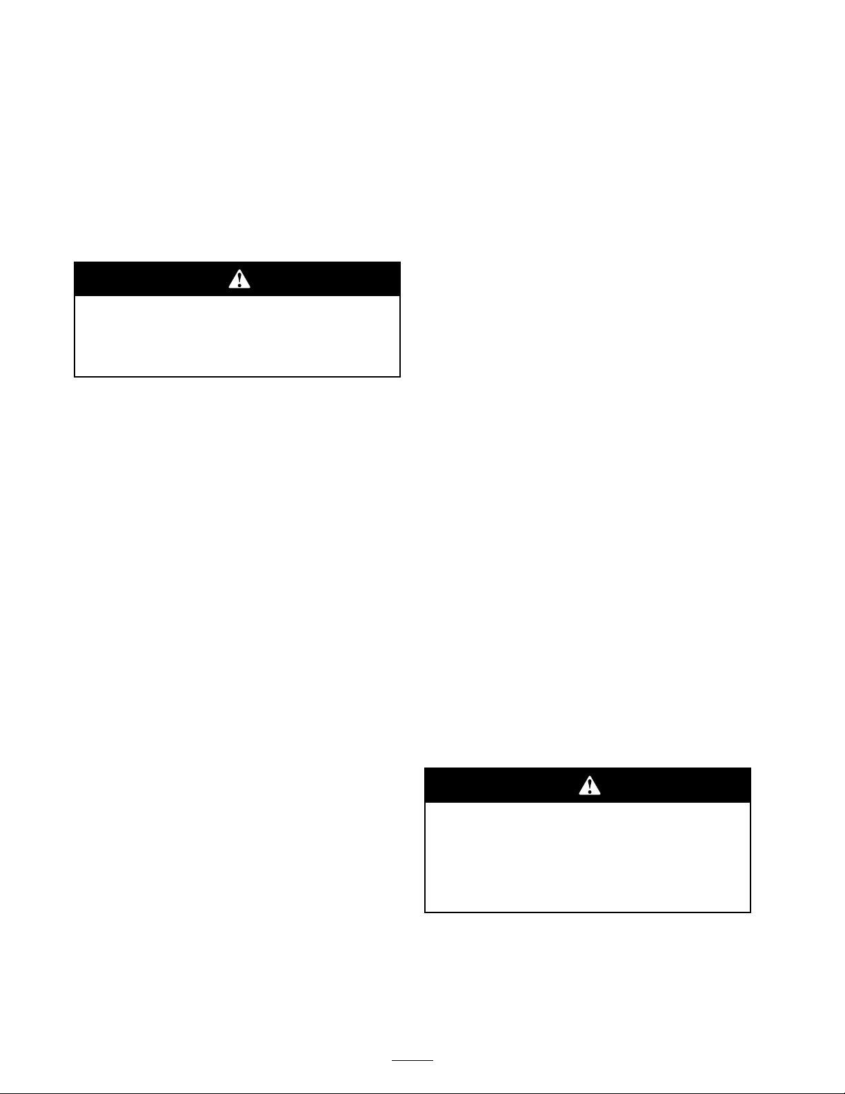
Safety and Instructional
Decals
107–0704
1. Warning—read the Operator’s Manual.
2. Collision hazard—do not operate the vehicle on public streets,
roads, or highways.
3. Falling hazard—do not carry passengers in the cargo bed.
4. Falling hazard—do not allow children to operate the vehicle. 10. To stop the engine, release the accelerator pedal, set the
5. Hour meter
6. Headlights
104–6581
1. Warning—read the Operator’s Manual .
2. Fire hazard—before fueling, stop the engine.
3. Tipping hazard—receive training before operating the machine, use caution and drive slowly while on slopes; drive slowly when
turning, keep the vehicle speed under 19 MPH (31 km/h) when carrying a full or heavy load and when driving on rough terrain .
4. Falling and arm/leg injury hazards—do not carry passengers in the cargo bed and keep arms and legs inside of the vehicle at all times.
7. Ignition—Off
8. Ignition—On
9. To start the engine, sit on the operator’s seat, put the gear
selector in Neutral, turn the ignition key on, pull the choke
lever out (if needed), and press the accelerator pedal.
parking brake, turn the ignition key off, and remove the
ignition key.
11. Electrical power (power point)
12. Horn
8
Page 9
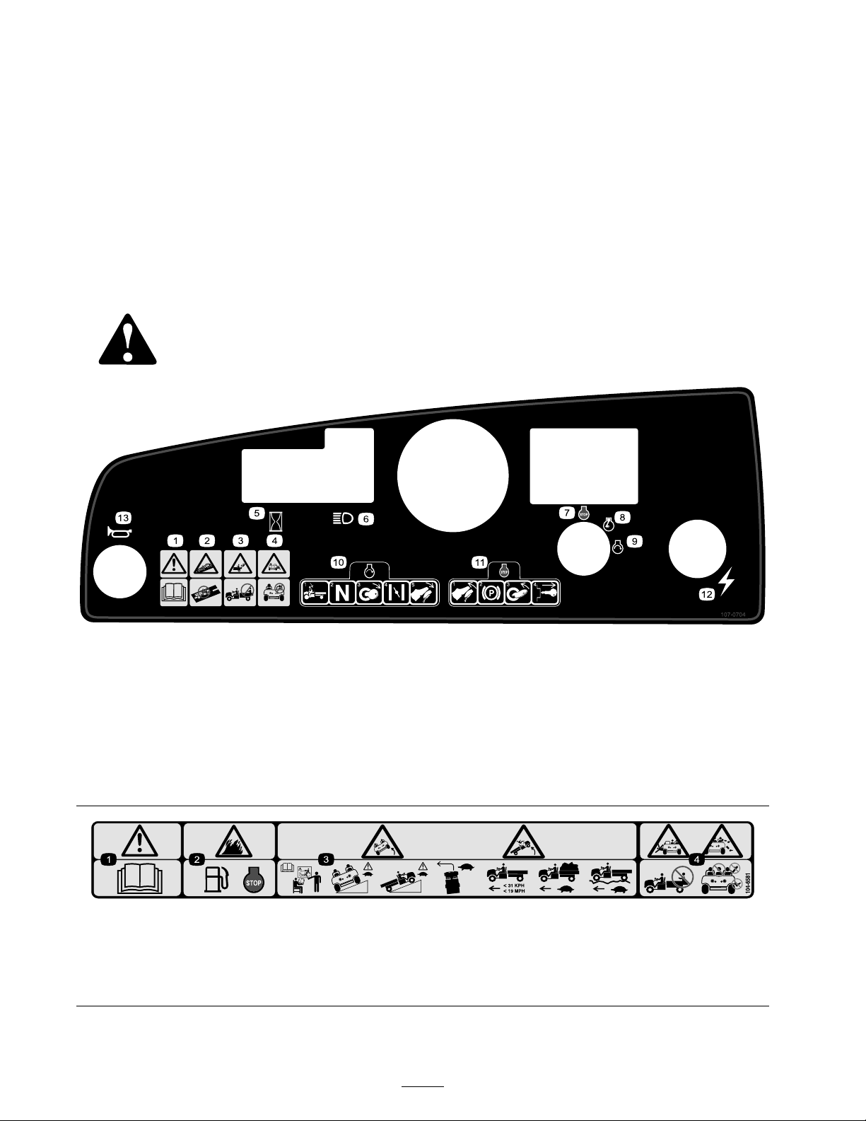
99–7345
1. Warning—read the Operator’s Manual .
2. Hot surface/burn hazard—stay a safe distance from the hot
surface.
3. Entanglement hazard, belt—stay away from moving parts
4. Crushing hazard, cargo box—use the prop rod to support
the cargo bed
99–7952
1. Choke 3. Neutral
2. Reverse
4. Forward
99–7350
1. Maximum tongue weight is 50 lb (23 kg); maximum trailer
weight is 400 lb (181 kg).
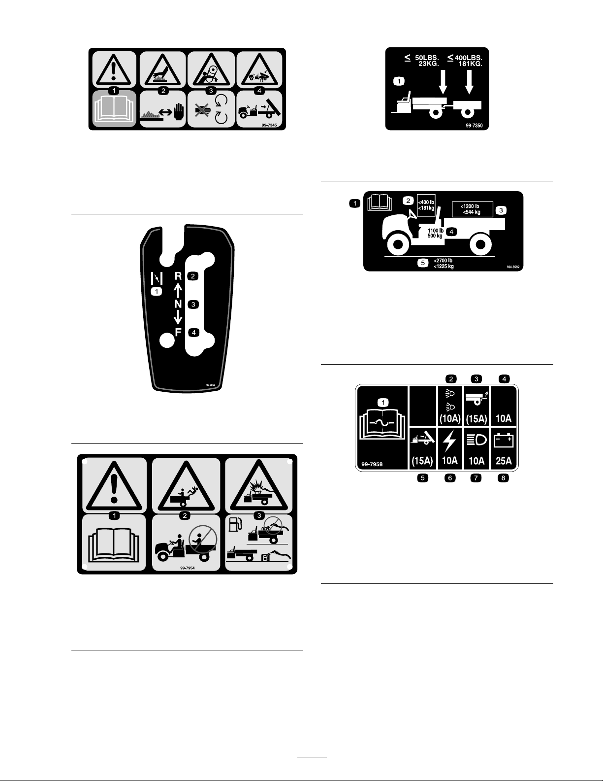
104–6592
1. Read the Operator’s
Manual.
2. The maximum combined
operator and passenger
weight is 400 lb (181 kg).
3. The maximum cargo
weight is 1200 lb (544 kg).
4. The base weight of the
vehicle is 1100 lb (500 kg).
5. The maximum gross
vehicle weight is 2700 lb
(1225 kg).
99–7954
1. Warning—read the Operator’s Manual .
2. Falling hazard—do not carry passengers in the cargo bed.
3. Explosion hazard, static discharge into fuel container—do
not ll fuel containers in the cargo bed; place fuel containers
on the ground before lling.
99–7958
1. Read the Operator’s Manual
for information on fuses.
2. 10 amp. fuse for the
optional Road Light Kit
3. 15 amp. fuse for the
optional Rear Lift Kit
4. 10 amp. fuse-open 8. 25 amp. fuse for the charge
5. 15 amp. fuse for the
optional Electric Bed Lift Kit
6. 10 amp. fuse for the low
oil light and the hour meter
7. 10 amp. fuse for the
headlights
circuit
9
Page 10

Setup
Loose Parts
Use the chart below to verify that all parts have been shipped.
Step
1
2
3
4
5
6
7
8
9
Wheel assembly
Steering wheel
Bumper 1
Seat 2
Hitch
Cargo box
Right-hand pivot bracket
Left-hand pivot bracket
Flange head screw (3/8 x 1 inch)
Bolt (5/16 x 3/4 inch)
Flange nut (5/16 inch)
No parts required
No parts required
Operator’s Manual
Engine Operator’s Manual
Parts Catalog
Safety Video
Registration Card
Predelivery Inspection Form
Key 2
Description
Qty.
4
1
1
1
1
1
4
1
1
–
–
1
1
1
1
1
1
Install the wheels.
Install the steering wheel.
Install the bumper.
Install the seats.
Install the hitch.
Install the cargo box.
Activate the battery.
Adjust the front wheel toe-in.
Read the Operator’s Manual and
watch the video before operating
the machine.
Use
Note: Deter mine the left and right sides of the
mac hine from the nor mal operating position.
10
Page 11
Step
Step
1
Installing the Wheels
Parts needed for this step:
4
Wheel assembly
Procedure
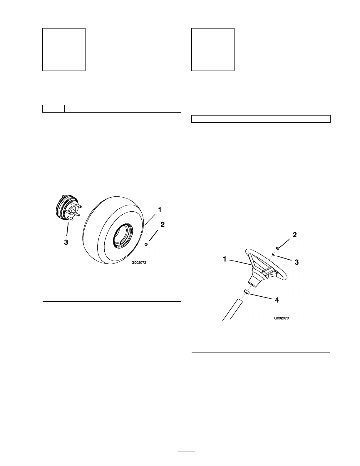
1. R emo v e the fasteners securing the wheels .
2. R emo v e the shipping brac k et secured to the
wheel studs .
3. Mount the wheels with the previously remo v ed
fasteners ( Figure 3 ) and tor que to 45-65 ft-lb
(61-88 N ⋅ m).
2
Installing the Steering
Wheel
Parts needed for this step:
1
Steering wheel
Procedure
1. R emo v e the n ut and loc k w asher from the
steering shaft.
2. Slide the steering wheel and w asher onto the
shaft. P osition the steering wheel on the shaft
so that the cross beam is horizontal when the
tires are pointed straight ahead and the thic k er
spok e of the steering wheel is do wnw ard.
3. Secure the steering wheel to the shaft with the
n ut ( Figure 4 ).
1. Wheel assembly
2. Wheel nut
Figure 3
3. Wheel stud (rear wheel hub
shown)
Figure 4
1. Steering wheel 3. Washer
2. Nut
4. Foam seal
11
Page 12
Step
Step
3
Installing the Bumper
Parts needed for this step:
1 Bumper
Procedure
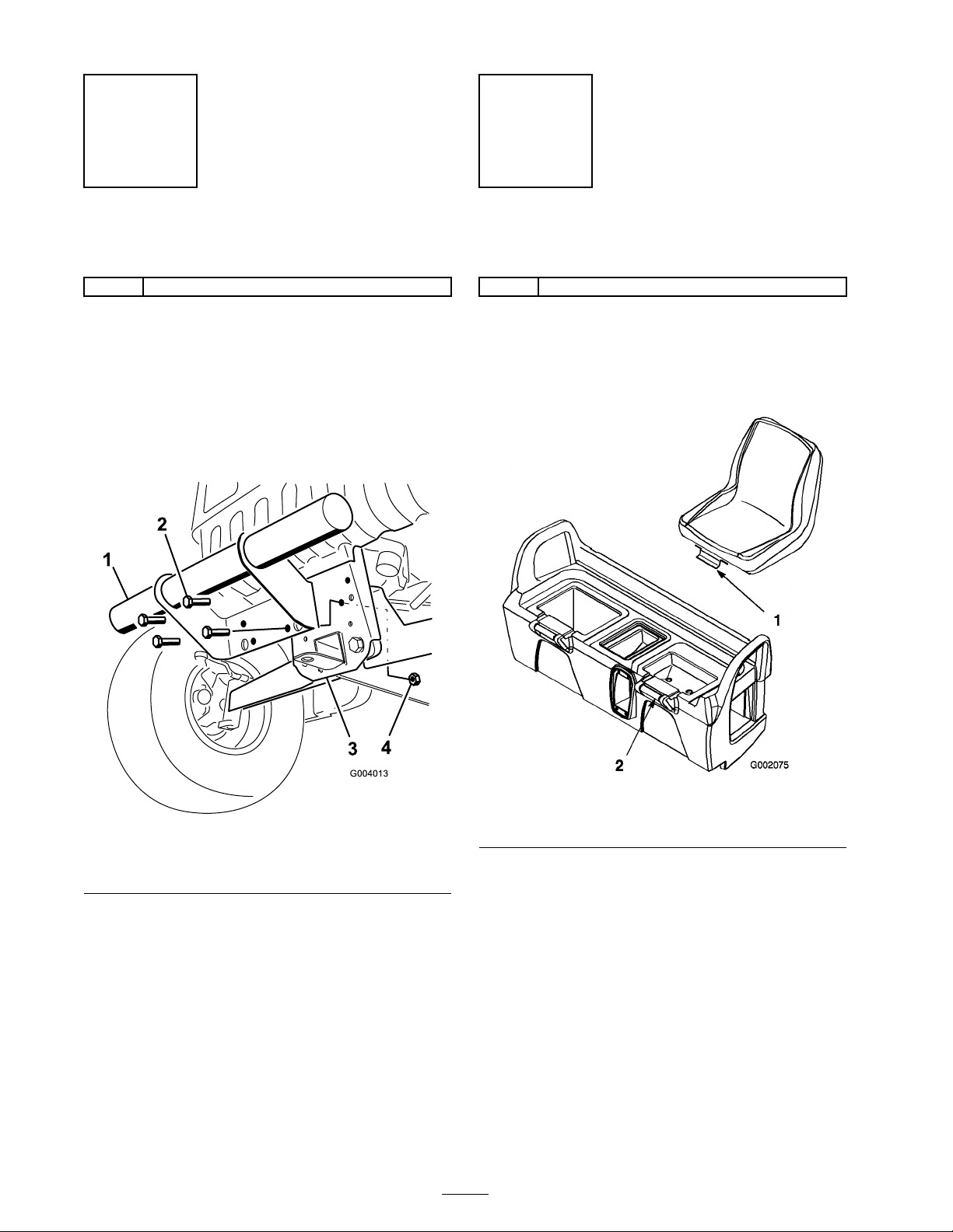
1. R emo v e the 4 bolts and loc k n uts secured to
the front of the frame .
2. Align the mounting holes and secure the
bumper to the frame with the fasteners
previously remo v ed ( Figure 5 ).
4
Installing the Seats
Parts needed for this step:
2 Seat
Procedure
Inser t the seat brac k et into the seat base opening
and pi v ot the seat do wnw ard ( Figure 6 ).
Figure 5
1. Bumper
2. Bolt 4. Lock nut
3. Frame
Figure 6
1. Seat bracket 2. Seat base
12
Page 13
Step
Step
5
Installing the Hitch
Parts needed for this step:
1
Hitch
Procedure
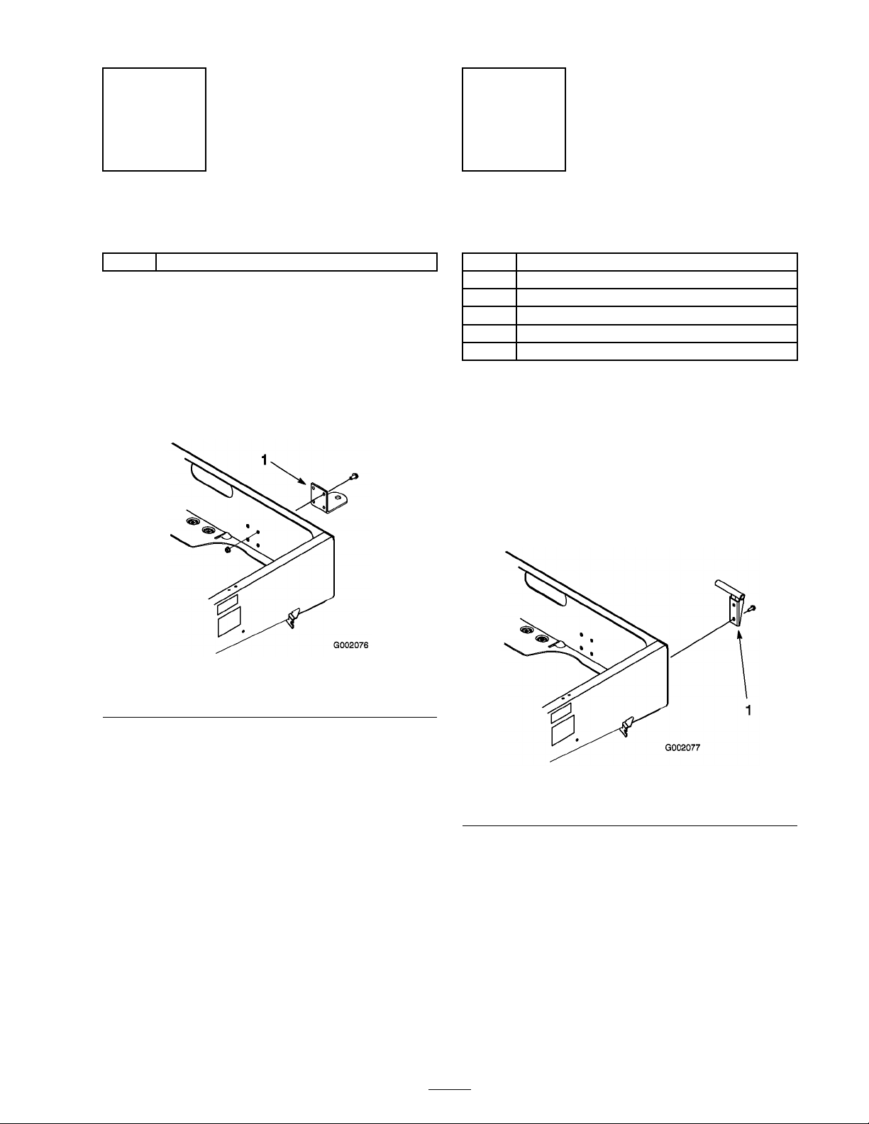
1. R emo v e the 4 bolts and n uts from the inside
rear of the frame .
2. Align the hitc h with the mounting holes on the
frame . Secure the hitc h with the screws and
n uts ( Figure 7 ).
6
Installing the Cargo Box
Parts needed for this step:
1
Cargo box
1
Right-hand pivot bracket
1
Left-hand pivot bracket
4
Flange head screw (3/8 x 1 inch)
1
Bolt (5/16 x 3/4 inch)
1
Flange nut (5/16 inch)
Procedure
1. P osition the carg o bo x onto the frame . T he
carg o bo x m ust la y flat and be centered.
2. Mount the left hand pi v ot brac k et to the left
rear cor ner of the frame with 2 flang e head
screws (3/8 x 1 inc h). P osition the brac k et as
sho wn in Figure 8 .
Figure 7
1. Hitch
Figure 8
1. Pivot bracket
3. Slide the carg o bo x mounting hole onto the
pi v ot brac k et ( Figure 9 ).
13
Page 14
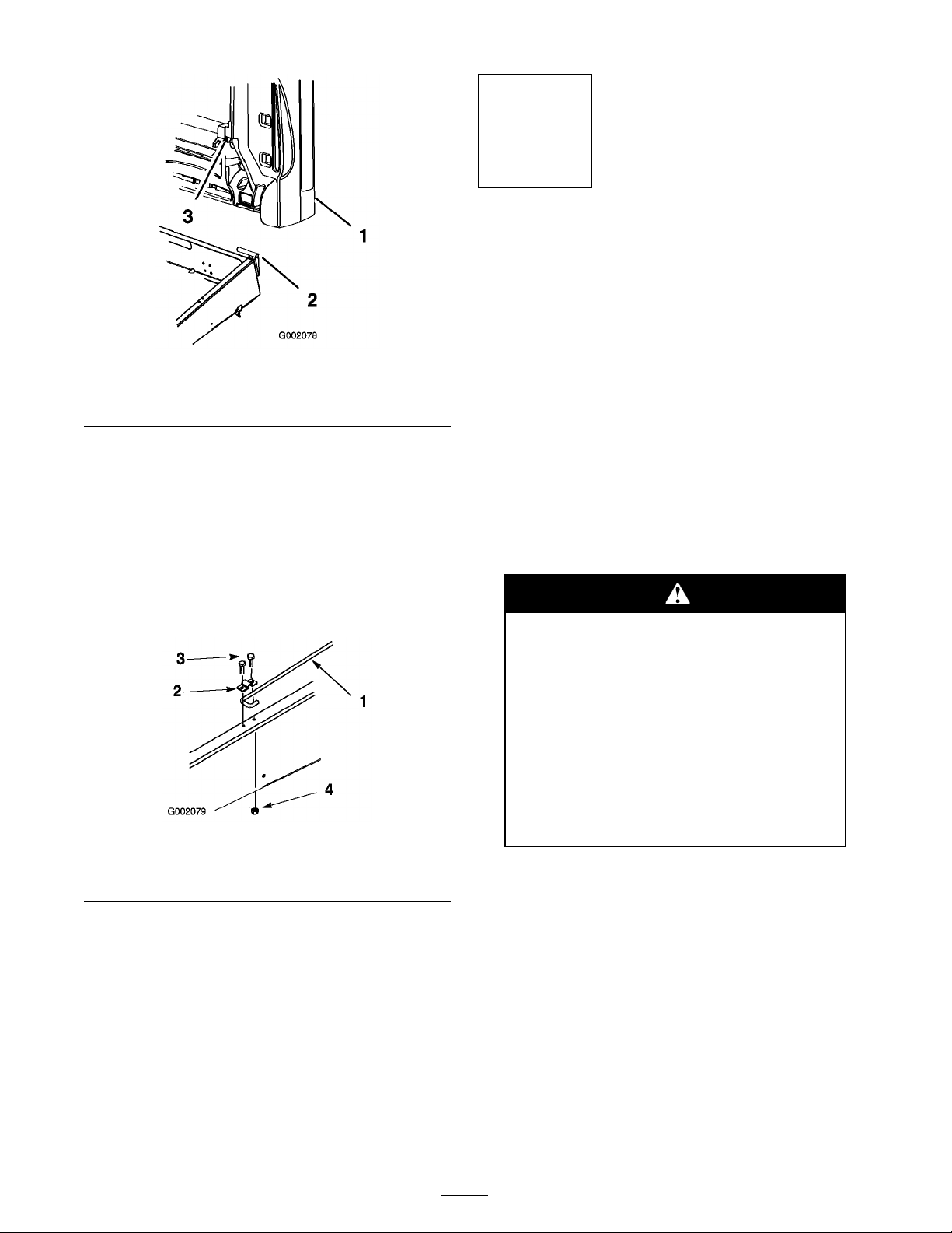
Figure 9
1. Cargo box 3. Cargo box mounting hole
2. Pivot bracket
4. Inser t the right hand pi v ot brac k et into the
mounting hole in the carg o bo x and then
mount it to the frame .
5. Ha v e another person help to raise the carg o
bo x.
6. Loosen the bolt securing the prop rod clip to
the frame until y ou can slide the J-hook end of
the prop rod under the clip ( Figure 10 ).
Step
7
Activating the Battery
No Parts Required
Procedure
None
Note: T his procedure is only needed for Model
No . 07277TC .
If the batter y is not filled with electrolyte or
acti v ated, it m ust be remo v ed from the v ehicle ,
filled with electrolyte , and c harg ed. Bulk electrolyte
with 1.260 specific g ra vity m ust be purc hased from
a local batter y supply outlet.
1. R emo v e the batter y hold-do wn and lift the
batter y out of the batter y base .
Batter y electr ol yte contains sulfuric acid
which is a deadl y poison and causes
sev er e bur ns.
Figure 10
1. Prop rod
2. Prop rod clip
7. Tighten the bolt and secure the other side of
the clip with a new bolt (5/16 x 3/4 inc h) and
flang e n ut (5/16 inc h) ( Figure 10 ).
8. Lo w er the carg o bo x.
3. Bolt (5/16 x 3/4 inch)
4. Flange nut (5/16 inch)
• Do not drink electr ol yte or allo w it to
contact y our skin, ey es or clothing .
W ear safety g lasses to shield y our
ey es and r ub ber g lo v es to pr otect y our
hands.
• Fill the batter y wher e clean w ater is
al w ays a v aila ble f or flushing the skin.
2. R emo v e the filler caps from the batter y and
slo wly fill eac h cell until electrolyte is just abo v e
the plates .
3. R e place the filler caps and connect a 3 to
4 amp . batter y c harg er to the batter y posts .
Charg e the batter y at a rate of 3 to 4 amperes
for 4 to 8 hours (12 v olts). Do not o v erc harg e
the batter y .
14
Page 15

Charging the batter y pr oduces gasses
that can explode.
Nev er smok e near the batter y and k eep
spar ks and flames a w ay fr om batter y .
4. W hen the batter y is c harg ed, disconnect the
c harg er from the electrical outlet and batter y
posts .
5. R emo v e the filler caps . Slo wly add electrolyte
to eac h cell until electrolyte is up to the fill line .
Install the filler caps .
Important: Do not o v erfill the batter y .
Electr ol yte will o v erflo w onto other par ts
of the v ehicle and sev er e cor r osion and
deterioration will r esult.
6. Install the batter y; refer to Installing the
Batter y , Electrical System Maintenance ,
pag e 32 .
If the v ehicle will be r un with medium to hea vy
loads most of the time , set the toe-in on the
high side of the recommended amount. If it
is g oing to be r un with a light load most of
the time , set the toe-in on the lo w side of the
recommended amount.
1. Measure the distance betw een both of the
front tires at the axle height at both the front
and rear of the front tires ( Figure 11 ). A fixture
or alignment g aug e is needed for the rear
measurement of the front tires at axle height.
Use the same fixture or alignment g aug e to
accurately measure the front of the front tires
at axle height ( Figure 11 ).
Step
8
Adjusting the Front Wheel
Toe-in
No Parts Required
Procedure
T he toe-in should be 1/8-5/8 inc h (3-16 mm) with
the follo wing parameters:
• T he tire pressure should be at 12 psi (83 kP a).
• T he ride height should be cor rect before
setting the toe-in; refer to the Adjusting the
F ront Suspension procedure in Maintenance ,
pag e 27 .
• T he v ehicle should be dri v en bac k and for th a
few times to relax the A-ar ms .
Figure 11
1. Tire center line-back
2. Tire center line-front 5. Axle center line distance
3. Axle center line
2. If the measurement does not fall within the
specified rang e (refer to the dimensions and
parameters at the beginning of this procedure),
loosen the jam n uts at both ends of the tie
rods ( Figure 45 ).
4. Fixture
6. 6 inches (15 cm) ruler
• Measure the toe-in with the wheels facing
straight ahead and a 175-225 lb (79-102 kg)
operator in the dri v er’ s seat.
Note: T he dri v er should dri v e up to the
measurement area and sta y seated in the v ehicle
while the measurement is being tak en.
15
Page 16

Figure 12
1. Jam nut
2. Tie rod
3. R otate both tie rods to mo v e the front of the
tire inw ard or outw ard.
4. Tighten the tie rod jam n uts when the
adjustment is cor rect.
5. Ensure that there is full tra v el of the steering
wheel in both directions .
Step
9
Reading the Manual and
Viewing the Safety Video
Parts needed for this step:
1
Operator’s Manual
1
Engine Operator’s Manual
1
Parts Catalog
1
Safety Video
1
Registration Card
1
Predelivery Inspection Form
2 Key
Procedure
• R ead the Operator’ s Manual and Engine Operator’ s
Manual .
• View the safety video .
• Fill out the registration card.
• Complete the Pr edeli ver y Inspection F or m and file
it in y our customer histor y por tfolio .
16
Page 17

Product Overview
Figure 13
1. Steering wheel 3. Parking brake 5. Cargo box 7. Cargo box release lever
2. Gear shift selector 4. Fuel cap
6. Towing tounge
Controls
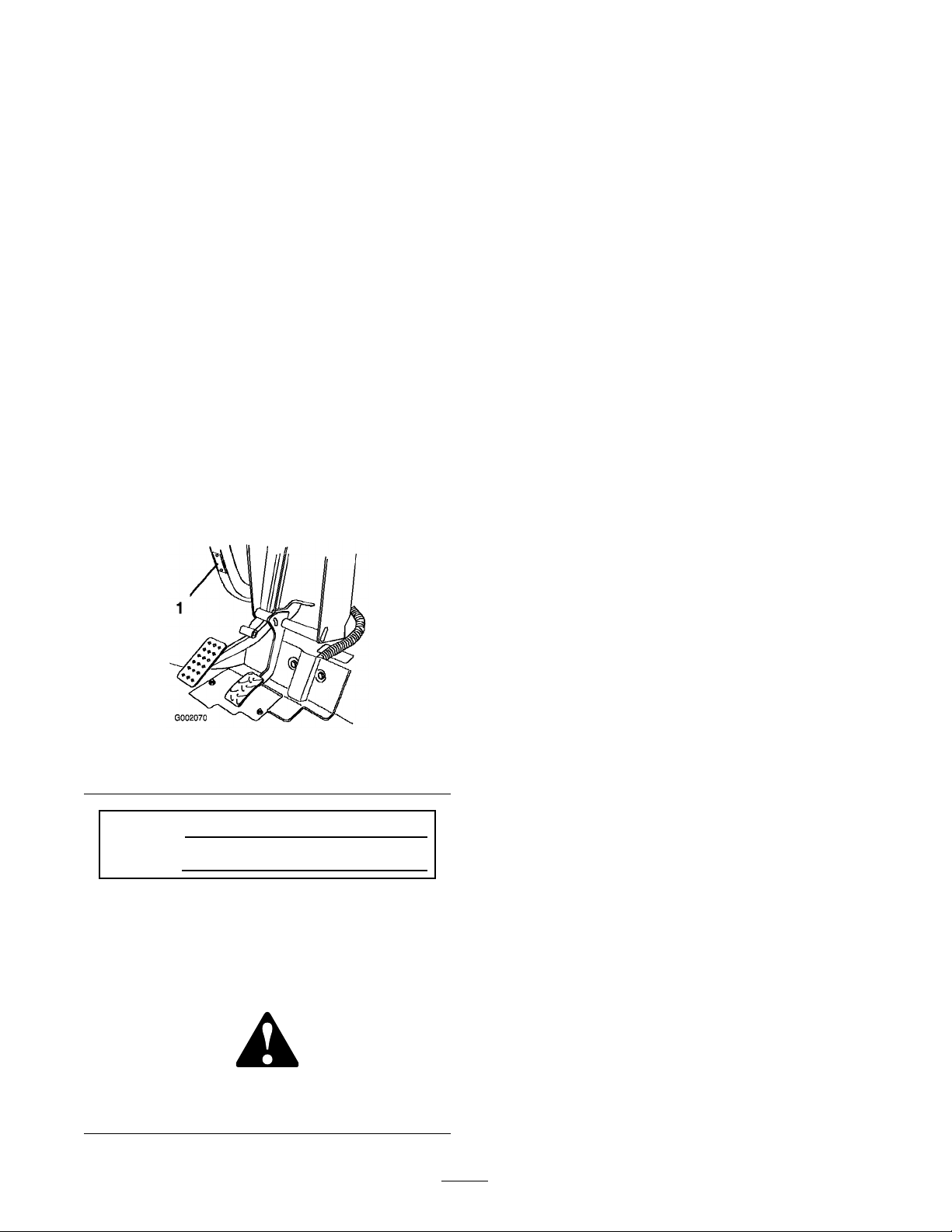
Accelerator Pedal
T he accelerator pedal ( Figure 14 ) gi v es the
operator the ability to v ar y g round speed of the
v ehicle . Pressing the pedal increases g round
speed. R eleasing the pedal will slo w the v ehicle .
Maxim um forw ard speed is 18 mph (26 km/h).
Figure 14
1. Accelerator pedal 2. Brake pedal
Brake Pedal
T he brak e pedal is used to stop or slo w the v ehicle
( Figure 14 ).
Brak es can become w or n or can be
misadjusted r esulting in per sonal injur y .
If brak e pedal tra v els to within 1 inch
(25 mm) of the v ehicle floor board, the
brak es must be adjusted or r epair ed.
Parking Brake
T he parking brak e is betw een the seats ( Figure 15 ).
W henev er the engine is shut off , the parking brak e
m ust be eng ag ed to prev ent accidental mo v ement
of the v ehicle . T o eng ag e the parking brak e , pull
bac k on the lev er . T o diseng ag e , push the lev er
forw ard. If the v ehicle is park ed on a stee p g rade ,
mak e sure that the parking brak e is applied. Place
bloc ks at the do wnhill side of the wheels .
17
Page 18

Figure 15
1. Parking brake lever
Choke Control
T he c hok e control is located belo w and to the
right of the operator’ s seat. T o star t a cold engine ,
pull the c hok e control outw ard ( Figure 16 ). After
the engine star ts , regulate the c hok e to k ee p the
engine r unning smoothly . As soon as possible ,
push the control in to the Off position. A w ar m
engine requires little or no c hoking .
to star t the engine . W hen the engine star ts , release
the k ey . W hen the v ehicle is stopped, rotate the
k ey countercloc kwise to the Off position to stop
the engine . R emo v e the k ey from the ignition.
Figure 17
1. Ignition switch 4. Oil light
2. Hour meter
3. Light switch
5. Power Point
6. Horn Button
Hour Meter
Figure 16
1. Choke 2. Gear shift selector
Gear Shift Selector
T he g ear shift selector has three positions:
F orw ard, R ev erse , and Neutral ( Figure 16 ). T he
g ear shift selector m ust be in Neutral to star t the
engine .
Note: If the g ear shift selector is in R ev erse when
the ignition is tur ned on, a buzzer will sound to
w ar n the operator .
Important: Al w ays stop the v ehicle bef or e
changing gear s.
Ignition Switch
T he ignition switc h ( Figure 17 ), used to star t and
stop the engine , has three positions: On, Off , and
Star t. R otate the k ey cloc kwise to the Star t position
T he hour meter ( Figure 17 ) indicates the total
n umber of hours the engine has r un.
Oil Light
T he oil light w ar ns the operator if the engine oil
lev el drops belo w a safe lev el ( Figure 17 ). If the
light comes on and remains lit, the oil lev el should
be c hec k ed and oil added if necessar y; refer to
Chec king the Engine Oil in Operation , pag e 21 .
Note: T he oil light ma y flic k er . T his is nor mal
and no action needs to be tak en.
Light Switch
T og gle the switc h to acti v ate the headlights . Push
to tur n the lights on ( Figure 17 ).
Power Point
Use the po w er point to po w er 12 v olt optional
electrical accessories ( Figure 17 ).
Horn Button
Press the hor n button to sound the hor n
( Figure 17 ).
Fuel Gauge
T he fuel g aug e ( Figure 18 ) sho ws the amount of
fuel in the tank.
18
Page 19

Figure 18
1. Fuel gauge
Passenger Hand Holds
T he passeng er hand holds are located on the right
side of the dash panel and at the outside of eac h
seat ( Figure 19 ).
Figure 19
1. Passenger hand hold
2. Hip restraint
19
Page 20

Specications
Note: Specifications and design are subject to c hang e without notice .
Base weight
Rated capacity (on level ground) 1600 lb (726 kg) total, including 200 lb (90.7 kg) operator and 200 lb (90.7 kg)
Maximum gross vehicle weight
(GVW) (on level ground)
Maximum cargo capacity (on
level ground)
Tow capacity:
Standard Hitch
Heavy Duty Hitch
Overall width
Overall length
Ground clearance
Wheel base
Wheel tread (center line to center
line)
Cargo box length
Cargo box width
Cargo box height
Dry 1050 lb (476 kg)
passenger, load, trailer tongue weight, gross trailer weight, accessories, and
attachments
2700 lb (1225 kg) total, including all of the weights listed above
1200 lb (544 kg) total, including trailer tongue weight and gross trailer weight
Tongue weight 50 lb (23 kg) Maximum trailer weight 400 lb (182 kg)
Tongue weight 100 lb (45 kg) Maximum trailer weight 800 lb (363 kg)
59 inches (150 cm)
115 inches (292 cm)
9-1/4 inches (23.5 cm) at the front with no load or operator, 7 inches (18 cm) at
the rear with no load or operator
79 inches (200.7 cm)
49 inches (124.5 cm) in the front, 48-1/4 inches (122.6 cm) in the rear
46 inches (116.8 cm) inside, 51 inches (129.5 cm) outside
49 inches (124.5 cm) inside, 54 inches (137.2 cm) outside
10 inches (25.4 cm) inside
Attachments/Accessories
A selection of T oro appro v ed attac hments and accessories are a v ailable for use with the mac hine to
enhance and expand its capabilities . Contact y our A uthorized Ser vice Dealer or Distributor or g o to
www .T oro .com for a list of all appro v ed attac hments and accessories .
20
Page 21

Operation
Note: Deter mine the left and right sides of the
mac hine from the nor mal operating position.
Think Safety First
Please carefully read all of the safety instr uctions
and decals in the safety section. Kno wing this
infor mation could help y ou or b ystanders a v oid
injur y .
Figure 20
1. Oil dipstick
Pre-Starting Checks
Chec k the follo wing items eac h time y ou begin
using the v ehicle for the da y:
• Chec k the tire pressure .
Note: T hese tires are different than car tires;
they require less pressure to minimize turf
compaction and damag e .
• Chec k all fluid lev els and add the appropriate
amount of specified fluids , if any are found to
be lo w .
• Chec k the brak e pedal operation.
• Ensure that the lights are w orking .
• T ur n the steering wheel to the left and right to
c hec k steering response .
• Chec k for oil leaks , loose par ts , and any other
noticeable malfunctions . Mak e sure the engine
is off and all mo ving par ts ha v e stopped before
c hec king for oil leaks , loose par ts , and other
malfunctions .
3. R emo v e the oil dipstic k and wipe the end clean.
4. Slide the oil dipstic k into the filler tube fully
seating it. Pull the dipstic k out and look at the
end.
If the oil lev el is lo w , remo v e the filler cap
and add oil of the proper type to raise the
lev el to , but not o v er , the Full mark on the
dipstic k. R efer to Ser vicing the Engine Oil in
Engine Maintenance , pag e 29 , for the proper
oil type and viscosity . Add the oil slo wly and
c hec k the lev el often during this process . Do
not o v erfill .
5. Install the oil dipstic k fir mly in place .
Checking the Brake Fluid
Level
Chec k the brak e fluid lev el before the engine is
first star ted; refer to Chec king the Brak e Fluid
Lev el in Brak e Maintenance , pag e 38 .
If any of the abo v e items are not cor rect
and y ou are not able to cor rect the problem,
contact y our A uthorized Ser vice Dealer .
Checking the Engine Oil
Note: T he engine is shipped with oil in the
crankcase; ho w ev er , the lev el of the oil m ust be
c hec k ed before and after the engine is first star ted.
Chec k the engine oil lev el before star ting the
engine eac h da y .
1. P osition the mac hine on a lev el surface .
2. Clean around the oil dipstic k ( Figure 20 ) so
dir t cannot fall into the hole and damag e the
engine .
Checking the Tire Pressure
Chec k the tire pressure ev er y 8 hours or daily to
ensure proper lev els .
T he air pressure rang e in the front and rear tires is
8–22 psi (55–103 kP a).
T he air pressure needed is deter mined b y the
pa yload car ried. T he lo w er the air pressure , the
less the compaction, smoother the ride , and tire
marks are minimized. Lo w er pressure should not
be used for hea vy pa yloads at high speeds .
Higher pressures should be used for hea vier
pa yloads at higher speeds . Do not ex ceed the
maxim um pressure .
21
Page 22

Adding Fuel
Use fresh, clean, unleaded regular g asoline suitable
for automoti v e use (87 pump octane minim um).
Leaded g asoline ma y be used if unleaded regular is
not a v ailable .
Important: Nev er use gasoline containing
methanol, gasoline containing mor e than
10% ethanol, gasoline additi v es, or white gas
because engine fuel system dama ge could
r esult.
In cer tain conditions, gasoline is extr emel y
flamma ble and highl y explosi v e. A fir e or
explosion fr om gasoline can bur n y ou and
other s and can dama ge pr oper ty .
• Fill the fuel tank outdoor s, in an open
ar ea, when the engine is cold. W ipe up
an y gasoline that spills.
• Nev er fill the fuel tank inside an enclosed
trailer .
• Do not fill the fuel tank completel y full.
Add gasoline to the fuel tank until the
lev el is 1/4 to 1/2 inch (6 to 13 mm)
belo w the bottom of the filler neck. T his
empty space in the tank allo ws gasoline
to expand.
In cer tain conditions during fueling , static
electricity can be r eleased causing a spar k
which can ignite the gasoline v apor s. A fir e
or explosion fr om gasoline can bur n y ou and
other s and can dama ge pr oper ty .
• Al w ays place gasoline container s on the
g r ound a w ay fr om y our v ehicle bef or e
filling .
• Do not fill gasoline container s inside
a v ehicle or on a tr uck or trailer bed
because interior car pets or plastic tr uck
bed liner s may insulate the container and
slo w the loss of an y static charge.
• W hen practical, r emo v e gas-po w er ed
equipment fr om the tr uck or trailer and
r efuel the equipment with its wheels on
the g r ound.
• If this is not possible, then r efuel such
equipment on a tr uck or trailer fr om a
por ta ble container , rather than fr om a
gasoline dispenser nozzle.
• If a gasoline dispenser nozzle must be
used, k eep the nozzle in contact with the
rim of the fuel tank or container opening
at all times until fueling is complete.
• Nev er smok e when handling gasoline,
and stay a w ay fr om an open flame or
wher e gasoline fumes may be ignited by
a spar k.
• Stor e gasoline in an appr o v ed container
and k eep it out of the r each of childr en.
Nev er buy mor e than a 30-day suppl y of
gasoline.
• Do not operate without entir e exhaust
system in place and in pr oper w or king
condition.
Filling the Fuel Tank
T he fuel tank capacity is appro ximately 7 g allons
(26.5 l).
1. Shut the engine off and set the parking brak e .
2. Clean the area around the fuel tank cap
( Figure 21 ).
Figure 21
1. Fuel tank cap
3. R emo v e the fuel tank cap .
4. Fill the tank to about 1 inc h (25 mm) belo w the
top of tank, (bottom of the filler nec k). T his
22
Page 23

space in the tank allo ws g asoline to expand.
Do not o v erfill .
5. Install the fuel tank cap securely . Wipe up any
fuel that ma y ha v e spilled.
Checking the Transmission
Stopping the Vehicle
T o stop the v ehicle , remo v e y our foot from the
accelerator pedal and slo wly press the brak e pedal.
Note: Stopping distance ma y v ar y de pending on
the v ehicle load and speed.
Oil Level
T he transaxle fluid lev el should be at the bottom
of the lev el indicator hole ( Figure 22 ). If it
is not, fill the reser v oir with the appropriate
fluid; refer to Changing the T ransaxle Fluid in
Dri v e System Maintenance , pag e 34 .
Figure 22
1. Level indicator hole
Starting the Engine
Important: Do not attempt to push or to w
the v ehicle to get it star ted.
Parking the Vehicle
1. Eng ag e the parking brak e and rotate the
ignition k ey to Off .
2. R emo v e the k ey from the ignition switc h to
prev ent accidental star ting .
Operating the Cargo Box
Raising the Box
Dri ving the v ehicle with the cargo bo x raised
may cause the v ehicle to tip or r oll easier .
T he bo x str uctur e may become dama ged if
y ou operate the v ehicle with the bo x raised.
• Onl y operate the v ehicle when the cargo
bo x is do wn.
• After dumping a load, lo w er the cargo
bo x.
1. Sit in the operator’ s seat.
2. Put the g ear shift selector in Neutral.
Note: T he engine will only star t in Neutral.
3. Inser t the k ey into the ignition switc h, tur n it
to the Star t position, and pull the c hok e out.
W hen the engine star ts , release the k ey .
Note: An engine that has been r unning and
is w ar m ma y not require pulling the c hok e out.
4. After the engine star ts and w ar ms up , slo wly
push the c hok e in to the Off position. If the
engine stalls or hesitates , pull the c hok e out for
a few more seconds before pushing it to Off .
5. R elease the parking brak e .
6. Mo v e the g ear shift selector to the desired
position.
7. T o dri v e the v ehicle , mo v e the g ear shift
selector to the desired position and slo wly ste p
on the accelerator pedal.
1. Lift the lev er on either side of the bo x and lift
the bo x up ( Figure 23 ).
Figure 23
1. Lever
2. Pull the prop rod into the detent slot, securing
the bo x ( Figure 24 ).
23
Page 24

2. T ur n the latc h post cloc kwise until it is sn ug
ag ainst the latc h and then tighten the n ut
( Figure 25 ).
3. R e peat this procedure for the latc h on the
other side of the v ehicle .
Operating the Tailgate Latches
Figure 24
1. Prop rod
Lowering the Box
T he w eight of the bo x may be hea vy . Hands
or other body par ts could be cr ushed.
K eep hands and other body par ts clear when
lo w ering the bo x.
Pull the prop rod out of the detent slot and lo w er
the bo x until it latc hes into place .
Adjusting the Box Latches
If the bo x latc h does not latc h tightly , vibrating up
and do wn as y ou dri v e the v ehicle , y ou can adjust
the latc h posts to mak e the latc hes fit sn ugly .
1. Loosen the n ut on the end of the latc h post
( Figure 25 ).
1. T o open the tailg ate latc hes , lift the latc h
handles up ( Figure 26 ). T he latc hes will spring
out to w ard the center of the tailg ate . Slo wly
lo w er the tailg ate .
Note: Y ou ma y need to push the end of the
tailg ate in (especially if there is a load ag ainst
the tailg ate) before the latc hes will spring
to w ard the center of the tailg ate and release .
Figure 26
1. Tailgate latch
2. T o close the tailg ate latc hes , lift the handles
upw ard and slide them to w ard the outside of
the v ehicle .
3. Push the latc h handles do wnw ard to secure the
latc h and tailg ate .
Figure 25
1. Latch 3. Latch post
2. Nut
Breaking in a New Vehicle
T o pro vide proper perfor mance and long
v ehicle life , follo w these guidelines for the first
100 operating hours:
• Chec k the fluid and engine oil lev els regularly
and be aler t for indications of o v erheating in
any component of the v ehicle .
• After star ting a cold engine , let it w ar m up for
about 15 seconds before accelerating .
• A v oid hard braking situations for the first
sev eral hours of new v ehicle break-in
operation. New brak e linings ma y not be at
optim um perfor mance until sev eral hours of
use has caused the brak es to become bur nished
(brok en-in).
24
Page 25

• V ar y the v ehicle speed during operation. A v oid
fast star ts and quic k stops .
• A break-in oil for engine is not required.
Original engine oil is the same type specified
for regular oil c hang es .
• R efer to the Maintenance section for any
special lo w hour c hec ks .
• Chec k the front suspension positioning
and adjust it if necessar y; refer to
Adjusting the F ront Suspension in
Dri v e System Maintenance , pag e 34 .
Loading the Cargo Box
Loose seats may f all of f of the v ehicle
and trailer when transpor ting and land on
another v ehicle or become an obstr uction
on the r oad.
R emo v e the seats or mak e sur e that the seats
ar e secur el y f astened in the detents.
T he capacity of the carg o bo x is 13 ft
3
(0.37 m
T he amount (v olume) of material that can be
placed in the bo x without ex ceeding the v ehicle
load ratings can v ar y g reatly de pending on the
density of the material. F or example , a lev el bo x of
w et sand w eighs 1500 lb (680 kg), whic h ex ceeds
the load rating b y 300 lb (136 kg). But a lev el bo x
of w ood w eighs 650 lb (295 kg), whic h is under
the load rating .
See the table belo w for load v olume limits with
v arious materials:
Material Max. cargo box capacity
Gravel, dry
Gravel, wet
Sand, dry 3/4 full
Sand, wet 1/2 full
Wood Full
Bark Full
Earth, packed
(on level ground)
3/4 full (approx.)
1/2 full (approx.)
3/4 full (approx.)
3
).
Figure 27
1. Tie down points
Towing the Vehicle
In case of an emerg ency , the v ehicle can be
to w ed for a shor t distance . Ho w ev er , w e do not
recommend this as a standard procedure .
T o wing at ex cessi v e speeds could cause a
loss of steering contr ol, r esulting in per sonal
injur y .
Nev er to w the v ehicle f aster than 5 mph
(8 km/h).
Transporting the Vehicle
F or mo ving the v ehicle long distances , a trailer
should be used. Mak e sure that the v ehicle is
secured to the trailer . R efer to Figure 27 and
Figure 28 for the location of the tie-do wn points .
T o wing the v ehicle is a tw o person job . If
the mac hine m ust be mo v ed a considerable
distance , transpor t it on a tr uc k or trailer; refer to
T ranspor ting the V ehicle .
1. R emo v e the dri v e belt; refer to R e placing the
Dri v e Belt in Belt Maintenance , pag e 39 .
2. Affix a to w line to the tongue on the front of
the frame ( Figure 28 ).
3. Put the v ehicle in neutral and release the
parking brak e .
25
Page 26

Figure 28
1. Towing tongue and tie down point
Towing a Trailer
T he v ehicle is capable of pulling trailers . T w o
types of to w hitc hes are a v ailable for the v ehicle ,
de pending on y our application. Contact y our
A uthorized T oro Distributor for details .
W hen hauling carg o or to wing a trailer , do not
o v erload y our v ehicle or trailer . Ov erloading can
cause poor perfor mance or damag e to the brak es ,
axle , engine , transaxle , steering, suspension, body
str ucture , or tires . Alw a ys load a trailer with 60%
of the carg o w eight in the front of the trailer . T his
places appro ximately 10% of the Gross T railer
W eight (GTW) on the to w hitc h of the v ehicle .
T he maxim um carg o load shall not ex ceed 1200 lb
(544 kg), including the GTW and tongue w eight.
F or example , if the GTW = 400 lb (181.5 kg) and
tongue w eight = 50 lb (23 kg), then the maxim um
carg o load = 750 lb (340 kg)
T o pro vide adequate braking and traction, alw a ys
load the carg o bo x when trailering . Do not ex ceed
the GTW limits .
A v oid parking a v ehicle with a trailer on a hill. If
y ou m ust park on a hill, eng ag e the parking brak e
and bloc k the trailer tires .
26
Page 27

Maintenance
Note: Deter mine the left and right sides of the mac hine from the nor mal operating position.
Recommended Maintenance Schedule(s)
Maintenance Service
Interval
After the rst 8 operating
hours
After the rst 25
operating hours
Before each use or daily
Every 50 hours
Every 100 hours
Maintenance Procedure
• Change the engine oil.
• Check the condition and tension of the drive belt.
• Check the front wheel toe-in and front suspension.
• Check the engine oil.
• Check the tire pressure.
• Check the transmission oil level.
• Check the brake uid level.
• Change the engine oil (twice as often in special operating conditions; refer
to Maintaining the Vehicle under Special Operating Conditions).
• Check the battery cable connections for wear or damage.
• Grease the bearings and bushings.
• Inspect and clean the air lter element (twice as often in special operating
conditions; refer to Maintaining the Vehicle under Special Operating
Conditions).
• Change the oil lter (twice as often in special operating conditions; refer to
Maintaining the Vehicle under Special Operating Conditions).
• Check the operation of the Neutral gear shift position.
• Inspect the condition and wear of the tires.
•
Torque the wheel lug nuts to 45-65 ft-lb (61-88 N ⋅ m).
• Check the front wheel toe-in and front suspension.
• Clean the engine cooling areas (twice as often in special operating
conditions; refer to Maintaining the Vehicle under Special Operating
Conditions).
• Inspect the brakes.
• Replace the air lter element.
Every 200 hours
Every 400 hours
Every 800 hours
Yearly
• Adjust the parking brake.
• Check the condition and tension of the drive belt.
• Inspect the fuel lines and connections.
• Clean and lubricate the primary drive clutch.
• Replace the spark plugs.
• Replace the fuel lter.
• Change the transaxle uid.
• Complete all yearly maintenance procedures specied in the Engine
Operator’s Manual.
Important: R efer to y our Engine Operator’ s Man ual f or additional maintenance pr ocedur es.
27
Page 28

Premaintenance
Procedures
Maintaining the Vehicle
under Special Operating
Conditions
If the v ehicle is subjected to any of the conditions
listed belo w , maintenance should be perfor med
twice as frequently .
• Deser t operation
• Cold climate operation (belo w 50° F [10° C])
• T railer to wing
• Dri ving time typically less than 5 min utes
• F requent operation in dusty conditions
• Constr uction w ork
• After extended operation in m ud, sand, w ater ,
or similar dir ty conditions , ha v e y our brak es
inspected and cleaned as soon as possible . T his
will prev ent any abrasi v e material from causing
ex cessi v e w ear .
• Under frequent hea vy duty operating
conditions , lubricate all g rease fittings and
inspect air cleaner daily to prev ent ex cessi v e
w ear .
( Figure 29 ) T he jac king point at the rear of the
v ehicle is under the axle tubes ( Figure 30 ).
Figure 29
1. Front jacking point
Figure 30
1. Rear jacking points
Jacking the Vehicle
W henev er the engine is r un for routine
maintenance and/or engine diagnostics , the rear
wheels of the v ehicle should be 1 inc h (25 mm)
off the g round with the rear axle suppor ted on
jac k stands .
T he v ehicle may be unsta ble when using
a jack. It could slip of f the jack, injuring
an y one beneath it.
• Do not star t the engine while the v ehicle
is on a jack.
• Al w ays r emo v e the k ey fr om the ignition
bef or e getting of f of the v ehicle.
• Block the tir es when the v ehicle is on a
jack.
T he jac king point at the front of the v ehicle is on
the front of the frame behind the to wing tongue
Lubrication
Lubricate all of the bearings and bushings ev er y
100 hours or once a year , whic hev er occurs first.
Grease them more frequently when using the
v ehicle for hea vy-duty operations .
Grease T ype: Number 2 General Pur pose Lithium
Base Grease
Adding Grease
1. Wipe the g rease fitting clean so foreign matter
cannot be forced into the bearing or bushing .
2. Pump g rease into the bearing or bushing .
3. Wipe off ex cess g rease .
T he g rease fittings are located at the four tie rod
ends ( Figure 31 and the tw o king pins ( Figure 32 ).
28
Page 29

Figure 31
Figure 32
4. Gently slide the filter out of the air cleaner
body to reduce the amount of dust dislodg ed
( Figure 33 ). A v oid knoc king the filter ag ainst
the air cleaner body .
Figure 33
1. Air cleaner latches 3. Filter
2. Cover
5. Inspect the filter and discard it if it is damag ed.
Engine Maintenance
Servicing the Air Cleaner
Chec k the air cleaner body for damag e whic h could
possibly cause an air leak. R e place a damag ed air
cleaner body .
Ensure the co v er is sealing around the air cleaner
body .
Air Cleaner Filter : Inspect after ev er y
100 operating hours; re place after ev er y 200 hours
or sooner if dir ty or damag ed.
Note: Ser vice the air cleaner more frequently
(ev er y few hours) if operating conditions are
extremely dusty or sandy .
Removing the Filter Element
1. P ark the mac hine on a lev el surface , set the
parking brak e , tur n the ignition off , and
remo v e the k ey .
2. Raise the bed and secure it with the prop rod.
3. R elease the latc hes securing the air cleaner
co v er to the air cleaner body . Se parate the
co v er from the body . Clean the inside of the
air cleaner co v er ( Figure 33 ).
Cleaning the Filter Element
Important: Do not w ash or r euse a dama ged
filter .
• W ashing method:
1. Pre pare a solution of filter cleaner and
w ater and soak the filter element for about
15 min utes . R efer to the directions on
the filter cleaner car ton for complete
infor mation.
2. After soaking the filter for 15 min utes , rinse
it with clear w ater . Rinse the filter from the
clean side to the dir ty side .
Important: T o pr ev ent dama ge
to the filter element, the maximum
w ater pr essur e must not ex ceed 40 psi.
(276 kP a).
3. Dr y the filter element using w ar m, flo wing
air at 160°F (71°C) maxim um, or allo w the
element to air -dr y .
Important: Do not use a light bulb to
dr y the filter element because dama ge
could r esult.
• Compr essed air method:
29
Page 30

1. Blo w compressed air from the inside to the
outside of the dr y filter element. K ee p the
air hose nozzle at least 2 inc hes (51 mm)
from the filter and mo v e the nozzle up and
do wn while rotating the filter element.
Important: T o pr ev ent dama ge to
the filter element, do not ex ceed 100 psi
(689 kP a) air pr essur e.
2. Inspect the filter element for holes and
tears b y looking through the filter to w ard a
bright light.
Installing the Filter Element
Important: T o pr ev ent engine dama ge,
al w ays operate the engine with the complete
air cleaner assembl y installed.
1. Inspect the new filter for shipping damag e .
Chec k the sealing end of the filter .
Important: Do not install a dama ged
filter .
2. Inser t the new filter into air cleaner body .
Ensure the filter is sealed properly b y applying
pressure to the outer rim of the filter when
installing it. Do not press on the flexible center
of the filter .
3. Install the co v er and secure the latc hes .
Servicing the Engine Oil
Chec k the oil lev el before eac h use .
Chang e the oil after the first 8 operating hours and
ev er y 50 hours thereafter . Chang e the oil twice
as often in special operating conditions; refer to
Maintaining the V ehicle under Special Operating
Conditions .
Viscosity: See the table belo w
Figure 34
Checking the Oil Level
T o c hec k the oil lev el, refer to Chec king the Engine
Oil in Operation , pag e 21 .
Changing the Oil
1. Star t the v ehicle and let it r un for a few min utes
to w ar m the oil.
2. P ark the mac hine on a lev el surface , set the
parking brak e , tur n the ignition off , and
remo v e the k ey .
3. Raise the bed and secure it with the prop rod.
4. Disconnect the spark plug wires and batter y
cables .
5. R emo v e the drain plug ( Figure 35 ) and let the
oil flo w into a drain pan. W hen the oil stops ,
install the drain plug .
Note: Dispose of the used oil at a cer tified
recycling center .
R e place the oil filter ev er y 100 hours .
Note: Chang e the oil and oil filter more
frequently when operating conditions are
extremely dusty or sandy .
Oil T ype: Deterg ent oil (API ser vice SF , SG , SH,
SJ , or higher)
Crankcase Capacity: 48 oz./1-1/2 qt. (1.4 liters)
when the filter is c hang ed
Figure 35
1. Engine oil drain plug 2. Engine oil lter
30
Page 31

6. P our oil into the fill opening until the oil lev el
is up to the Full mark on the dipstic k. Add the
oil slo wly and c hec k the lev el often during this
process . Do not o v erfill .
7. Install the oil fill cap and dipstic k fir mly in
place .
8. Connect the spark plug wires and batter y
cables .
Changing the Oil Filter
R e place the oil filter ev er y 100 operating hours or
yearly , whic hev er occurs first.
1. Drain the oil from the engine; refer to
Changing the Oil.
2. R emo v e the existing oil filter ( Figure 35 ).
3. Apply a light coat of clean oil to the new filter
g ask et.
4. Screw the new filter on until the g ask et
contacts the mounting plate , then tighten the
filter an additional 1/2 to 3/4 tur n fur ther . Do
not o v er tighten .
5. Fill the crankcase with the proper type of new
oil.
6. Star t and r un the engine to c hec k for leaks .
7. Stop the engine and c hec k the oil lev el. Add
oil if necessar y .
Servicing the Spark Plugs
R e place the spark plugs after ev er y 800 operating
hours or yearly , whic hev er occurs first, to ensure
proper engine perfor mance and reduce the exhaust
emission lev el.
Figure 36
1. Center electrode insulator
2. Side electrode
Important: A crack ed, f ouled, dir ty ,
or malfunctioning spar k plug must be
r eplaced. Do not sandblast, scrape, or
clean the electr odes by using a wir e br ush
because g rit may ev entuall y r elease fr om
the plug and f all into the cylinder . T he
r esult is usuall y a dama ged engine.
4. Set the air g ap betw een the center and side
electrodes at 0.030 inc h (0.762 mm) ( Figure 36 ).
5. Install the cor rectly g apped spark plug and
tighten the plug to 18-22 ft-lb (24-30 N ⋅ m). If
a tor que wrenc h is not used, tighten the plug
fir mly .
6. Install the spark plug wires .
3. Air gap (not to scale)
Fuel System
Maintenance
T ype: Champion R C 14Y C (or equi v alent)
Air Gap: 0.030 inc h (0.762 mm)
Note: T he spark plugs usually lasts a long
time; ho w ev er , the plugs should be remo v ed and
c hec k ed whenev er the engine malfunctions .
1. Clean the area around the spark plugs so that
foreign matter cannot fall into the cylinder
when the spark plug is remo v ed.
2. Pull the spark plug wires off of the spark plugs
and remo v e the plugs from the cylinder head.
3. Chec k the condition of the side electrode ,
center electrode , and center electrode insulator
to ensure that there is no damag e ( Figure 36 ).
Inspecting Fuel Lines and
Connections
Chec k the fuel lines and connections ev er y 400
operating hours or yearly , whic hev er occurs first.
Inspect them for deterioration, damag e , or loose
connections .
Replacing the Fuel Filter
R e place the fuel filter ev er y 800 operating hours
or yearly , whic hev er occurs first.
1. Raise the bo x and suppor t it with the prop rod.
2. Place a clean container under the fuel filter .
31
Page 32

3. R emo v e the clamps securing the fuel filter to
the fuel lines ( Figure 37 ), as follo ws:
A. Squeeze the clamp tabs tog ether and slide
the clamps up the hose off of the filter
hose fittings .
B . Pull the hose ends off of the filter hose
fittings .
Figure 38
1. Charge circuit
2. Lights 4. Low oil light and hour
3. Power point
meter
Replacing the Headlights
Figure 37
1. Fuel lter
4. Install the re placement filter to the fuel lines
with the clamps previously remo v ed.
Mount the filter so that the ar ro w points
to w ard the carburetor .
Electrical System
Maintenance
Replacing the Fuses
T here are 3 fuses in the electrical system. T hey are
located beneath the bed in a bo x on the right hand
side of the frame ( Figure 38 ).
Charge circuit
Lights
Power Point
Low oil light and hour
meter
10 amp. (15 amp. max.)
25 amp.
10 amp.
10 amp.
Specification: GE #862
1. Set the parking brak e , tur n the ignition off , and
remo v e the k ey .
2. Switc h the headlights off .
3. R eac h beneath the dash and rotate the
lamp assembly 1/4 tur n countercloc kwise
( Figure 39 ).
Figure 39
1. Lamp assembly 3. Tabs
2. Reector 4. Slots
4. Pull the lamp assembly out of the reflector .
5. R emo v e the lamp assembly from the wire
har ness .
6. Discard the lamp assembly .
7. Push the re placement lamp assembly onto the
wire har ness .
8. R eac h beneath the dash and align the three
tabs on the lamp assembly with the slots in the
reflector ( Figure 39 ).
9. Inser t the lamp assembly into the reflector and
rotate it 1/4 tur n cloc kwise until it stops .
32
Page 33

Servicing the Battery
Important: Do not jump star t the v ehicle.
Alw a ys k ee p the batter y clean and fully c harg ed.
Use a paper to w el to clean the batter y and batter y
bo x. If the batter y ter minals are cor roded, clean
them with a solution of four par ts w ater and one
par t baking soda. Apply a light coating of g rease
to the batter y ter minals to prev ent cor rosion.
V oltag e: 12 v olt with 280 cold cranking Amps @
0° F (-18° C).
Removing the Battery
1. P osition the v ehicle on a lev el surface , set
the parking brak e , tur n the ignition off , and
remo v e the k ey .
2. Raise the bed and secure it with the prop rod.
3. R emo v e the batter y hold-do wn.
4. Disconnect the neg ati v e (blac k) g round cable
from the batter y post.
Batter y ter minals or metal tools could
shor t a gainst metal v ehicle components,
causing spar ks. Spar ks can cause the
batter y gasses to explode, r esulting in
per sonal injur y .
• W hen r emo ving or installing the
batter y , do not allo w the batter y
ter minals to touch an y metal par ts of
the v ehicle.
• Do not allo w metal tools to shor t
betw een the batter y ter minals and
metal par ts of the v ehicle.
5. Disconnect the positi v e (red) cable from the
batter y post.
6. R emo v e the batter y from the c hassis .
Installing the Battery
1. Set the batter y on the batter y base so the
batter y posts are to w ard the rear of the v ehicle .
Incor r ect batter y ca ble r outing could
dama ge the v ehicle and ca bles, causing
spar ks. Spar ks can cause the batter y
gasses to explode, r esulting in per sonal
injur y .
• Al w ays disconnect the negati v e
(black) batter y ca ble bef or e
disconnecting the positi v e (r ed)
ca ble.
• Al w ays r econnect the positi v e (r ed)
batter y ca ble bef or e r econnecting the
negati v e (black) ca ble.
• Al w ays k eep the batter y strap in place
to pr otect and secur e the batter y .
2. Connect the positi v e (red) cable to the positi v e
(+) batter y post and the neg ati v e (blac k) cable
to the neg ati v e (-) batter y post using the bolts
and wing n uts . Slide the r ubber boot o v er the
positi v e batter y post.
3. R e place the batter y hold-do wn to secure the
batter y to the base .
Important: Al w ays k eep the batter y
hold-do wn in place to pr otect and secur e
the batter y .
Charging the Battery
Important: Al w ays k eep the batter y
full y charged (1.260 specific g ra vity). T his
is especiall y impor tant to pr ev ent batter y
dama ge when the temperatur e is belo w 32°F
(0°C).
1. R emo v e the batter y from the c hassis; refer to
R emo ving the Batter y .
2. Connect a 3 to 4 amp batter y c harg er to the
batter y posts . Charg e the batter y at a rate of 3
to 4 amperes for 4 to 8 hours (12 v olts). Do
not o v erc harg e the batter y .
33
Page 34

Charging the batter y pr oduces gasses
that can explode.
Nev er smok e near the batter y and k eep
spar ks and flames a w ay fr om batter y .
3. Install the batter y in the c hassis; refer to
Installing the Batter y .
Storing the Battery
If the mac hine will be stored for more than
30 da ys , remo v e the batter y and c harg e it fully .
Either store it on the shelf or on the mac hine .
Lea v e the cables disconnected if it is stored on the
mac hine . Store the batter y in a cool atmosphere
to a v oid quic k deterioration of the c harg e in the
batter y . T o prev ent the batter y from freezing,
mak e sure it is fully c harg ed.
Drive System
Maintenance
Figure 40
1. Neutral bracket 2. Locknuts
3. Tighten one of the loc kn uts ( Figure 40 ) just
enough to tak e the slac k out of the shift cable .
Note: Y ou m ust hold the threaded shaft
belo w the brac k et to tighten the loc kn ut on top .
4. Tighten the other loc kn ut just enough to tak e
the slac k out of the other shift cable .
Checking and Adjusting
Neutral
W hen perfor ming routine maintenance and/or
engine diagnostics , the transaxle m ust be shifted
into neutral ( Figure 40 ). T he v ehicle has a neutral
position on the shift lev er , whic h controls the
neutral in the transaxle . T he follo wing ste ps
should be tak en to mak e sure that the neutral shift
lev er operates the transaxle neutral cor rectly:
1. Set the shift lev er into the Neutral position.
2. Ensure that the neutral brac k et is in the neutral
position (lev el) b y tur ning the dri v e clutc h
( Figure 40 ). T he v ehicle should not roll bac k
and for th. If it does , man ually mo v e the neutral
brac k et to the neutral position.
5. Pull up on eac h shift cable an ensure that there
is no g ap betw een the n ut/w asher and the
neutral brac k et ( Figure 41 ). If there is a g ap ,
tighten the n ut.
Figure 41
1. Neutral bracket 4. Wrong, must tighten the
nut
2. Pull up 5. Correct adjustment
3. Cable boot
6. Star t the engine and shift into F orw ard,
R ev erse , and Neutral sev eral times to ensure
that the neutral brac k et is operating properly .
34
Page 35

Inspecting the Tires
Chec k the tire condition at least ev er y 100 hours
of operation. Operating accidents , suc h as hitting
curbs , can damag e a tire or rim and also disr upt
wheel alignment, so inspect tire condition after an
accident.
Chec k the wheels to ensure that they are mounted
securely . T or que the lug n uts to 45-65 ft-lb
(61-88 N ⋅ m).
Adjusting the Front
Suspension
T he ride height of eac h side of the v ehicle can
be adjusted se parately . T he ride height should be
8-3/4 to 9-1/2 inc hes (22.2 to 24 cm) with the
follo wing parameters:
• T he tire pressure should be at 12 psi (83 kP a).
• T he v ehicle should be dri v en bac k and for th a
few times to relax the A-ar ms .
• Measure the ride height with the wheels facing
straight ahead and a 175-225 lb (79-102 kg)
operator in the dri v er’ s seat.
Note: T he dri v er should dri v e up to the
measurement area and sta y seated in the v ehicle
while the measurement is being tak en.
• Measure the ride height on a flat surface , from
the bottom of the front tongue to the g round.
1. J ac k the front end of the v ehicle off of
the g round; refer to J ac king the V ehicle in
Premaintenance Procedures , pag e 28 .
2. R emo v e the tra v el limiting bolt ( Figure 42 ).
3. Loosen the centering bolts in the front A-ar m
( Figure 42 ).
Figure 42
1. Travel limiting bolt 3. Ride height adjustment
bolt
2. Centering bolt
5. R otate the front A-ar m to the desired position
(refer to the note belo w) and re place the ride
height adjustment bolt ( Figure 42 ).
Note: T he A-ar ms are made with r ubber
and ha v e different spring rates . Because of
the different spring rates , the A-ar ms come
adjusted from the factor y based on that spring
rate . Generally the adjustment bolts will be
installed in hole n umber 2, 3, or 4 ( Figure 43 )
and it ma y be different from the left side (dri v er
side) to the right side (passeng er side). If the
A-ar ms look lik e they are sag ging, then they
should be adjusted to the next higher n umber
( Figure 43 ). Eac h hole equals about 3/4 inc h
(19 mm) of adjustment at the wheel. Y ou will
also need to do this if y ou are adding hea vy
attac hments or car r ying hea vy loads often.
4. R emo v e the ride height adjustment bolt
( Figure 42 ).
35
Page 36

Figure 43
1. Left-hand A-arm
6. T or que the ride height adjustment bolt to
135-165 ft-lb (183-224 N ⋅ m).
7. R e place the tra v el limiting bolt ( Figure 42 ).
Note: T he dri v er should dri v e up to the
measurement area and sta y seated in the v ehicle
while the measurement is being tak en.
If the v ehicle will be r un with medium to hea vy
loads most of the time , set the toe-in on the
high side of the recommended amount. If it
is g oing to be r un with a light load most of
the time , set the toe-in on the lo w side of the
recommended amount.
1. Ensure that the front suspension is adjusted
properly; refer to Adjusting the F ront
Suspension. Adjust if necessar y .
2. Measure the distance betw een both of the
front tires at the axle height at both the front
and rear of the front tires ( Figure 44 ). A fixture
or alignment g aug e is needed for the rear
measurement of the front tires at axle height.
Use the same fixture or alignment g aug e to
accurately measure the front of the front tires
at axle height ( Figure 44 ).
Note: T he v ehicle ma y need to be lo w ered to
the g round on that side to install the bolt.
8. Tighten and tor que the centering bolts to
240-290 ft-lb (325-393 N ⋅ m).
9. Chec k the ride height at the front tongue per
the dimensions and parameters gi v en at the
beginning of this procedure .
Adjusting Front Wheel
Toe-In
Chec k the front wheel toe-in after ev er y
100 operating hours , or ann ually , whic hev er occurs
first.
T he toe-in should be 1/8-5/8 inc h (3-16 mm) with
the follo wing parameters:
• T he tire pressure should be at 12 psi (83 kP a).
• T he ride height should be cor rect before
setting the toe-in; refer to Adjusting the F ront
Suspension.
Figure 44
1. Tire center line-back
2. Tire center line-front 5. Axle center line distance
3. Axle center line
4. Fixture
6. 6 inches (15 cm) ruler
3. If the measurement does not fall within the
specified rang e (refer to the dimensions and
parameters at the beginning of this procedure),
loosen the jam n uts at both ends of the tie
rods ( Figure 45 ).
• T he v ehicle should be dri v en bac k and for th a
few times to relax the A-ar ms .
• Measure the toe-in with the wheels facing
straight ahead and a 175-225 lb (79-102 kg)
operator in the dri v er’ s seat.
36
Page 37

Figure 45
1. Jam nut
2. Tie rod
4. R otate both tie rods to mo v e the front of the
tire inw ard or outw ard.
5. Tighten the tie rod jam n uts when the
adjustment is cor rect.
6. Ensure that there is full tra v el of the steering
wheel in both directions .
Maintaining the Primary
Drive Clutch
T he dust in the clutch will become
airbor ne and could dama ge y our ey es or
y ou could inhale it causing br eathing
dif ficulties.
W ear safety go g g les and a dust mask
or other ey e and r espirator y pr otection
when perf or ming this pr ocedur e.
5. Lubricate the mo ving par ts in the areas circled
in Figure 47 using T oro Dr y Lubricant Spra y ,
a v ailable through y our A uthorized T oro Dealer
or Distributor .
After ev er y 400 operating hours or yearly , clean
and lubricate the clutc h as follo ws:
1. Raise and latc h the carg o bo x.
2. Stop the engine , remo v e the k ey , and set the
parking brak e .
3. R emo v e the 3 bolts securing the co v er to the
clutc h and remo v e the co v er ( Figure 46 ).
Figure 46
1. Cover
2. Bolts
4. T horoughly clean the inside of the co v er
and the inner w orkings of the clutc h using
compressed air .
Figure 47
6. Install the clutc h co v er and secure it with the 3
bolts remo v ed previously .
Changing the Transaxle
Fluid
Chang e the transaxle fluid ev er y 800 operating
hours or yearly , whic hev er occurs first.
1. P osition the v ehicle on a lev el surface , set
the parking brak e , tur n the ignition off , and
remo v e the k ey .
2. R emo v e the drain plug from the right side of
the reser v oir ( Figure 48 ) and let the fluid flo w
into a drain pan. Install and tighten the plug
when the fluid stops draining .
Note: Dispose of the used oil at a cer tified
recycling center .
37
Page 38

Important: Nev er clean the engine with
pr essuriz ed w ater because w ater could
contaminate the fuel system.
Brake Maintenance
Inspecting the Brakes
Figure 48
1. Drain plug 2. Level indicator hole
3. Fill the reser v oir ( Figure 49 ) with appro ximately
1-1/2 qt. (1.4 liters) of SAE 10W30 motor oil
or until the oil lev el is at the bottom of the
lev el indicator hole ( Figure 48 ).
Figure 49
1. Oil ll
4. Star t the engine and operate it to fill the
system. R ec hec k the oil lev el and re plenish it,
if required.
Brak es are a critical safety component of the
v ehicle . As with all safety components , they should
be closely inspected at regular inter v als to ensure
optim um perfor mance and safety . T he follo wing
inspections should be done ev er y 100 hours:
• Inspect the brak e shoes for w ear or damag e .
If the lining (brak e pad) thic kness is less than
1/16 inc h (1.6 mm), the brak e shoes should
be re placed.
• Inspect the bac king plate and other
components for signs of ex cessi v e w ear or
defor mation. If any defor mation is found, the
appropriate components m ust be re placed.
• Chec k the brak e fluid lev el; refer to Chec king
the Brak e Fluid Lev el.
Checking the Brake Fluid
Level
T he brak e fluid reser v oir is filled and shipped from
the factor y with DOT 3 brak e fluid. Chec k the
lev el before the engine is first star ted and ev er y 8
hours or daily , thereafter .
Cooling System
Maintenance
Cleaning the Engine Cooling
Areas
Clean the rotating screen, cooling fins , and exter nal
surfaces of the engine ev er y 100 operating hours
or more often under extremely dusty and dir ty
conditions .
Important: Operating the engine with a
block ed r otating scr een, dir ty or plug ged
cooling fins, or cooling shr ouds r emo v ed will
cause engine dama ge due to o v erheating .
1. P ark the mac hine on a lev el surface , set the
parking brak e , tur n the ignition off , and
remo v e the k ey .
2. Look at the side of the reser v oir . T he lev el
should be abo v e the Minim um line ( Figure 50 ).
If the fluid lev el is lo w , clean the area around
the cap , remo v e the cap , and fill the reser v oir
to abo v e the Minim um line . Do not o v erfill.
38
Page 39

Figure 50
1. Brake uid reservoir 2. Minimum line
Adjusting the Parking Brake
Chec k the parking brak e adjustment ev er y 200
hours .
1. Pr y the r ubber co v er off of the parking brak e .
2. Loosen the set screw securing the knob to the
parking brak e lev er ( Figure 51 ).
1. P ark the mac hine on a lev el surface , shift into
Neutral, set the parking brak e , tur n the ignition
off , and remo v e the k ey .
2. Raise the bed and secure it with the prop rod.
3. R otate and inspect the belt ( Figure 52 ) for
ex cessi v e w ear or damag e . R e place the belt if
necessar y .
Figure 52
1. Drive belt 3. Secondary clutch
2. Primary clutch
Figure 51
1. Parking brake lever
2. Knob
3. Set screw
3. R otate the knob until a force of 30-35 lb
(133-156 N) is required to actuate the lev er .
4. Tighten the set screw and install the r ubber
co v er .
Belt Maintenance
Servicing the Drive Belt
Checking the Drive Belt
Chec k the condition and tension of the dri v e
belt after the first da y of operation and ev er y
200 operating hours thereafter .
Replacing the Drive Belt
1. R otate and route the belt o v er the secondar y
clutc h ( Figure 52 ).
2. R emo v e the belt from the primar y clutc h
( Figure 52 ).
3. T o re place the belt, rev erse the procedure .
Cleaning
Washing the Vehicle
T he v ehicle should be w ashed as needed. Use
w ater alone or with a mild deterg ent. A rag ma y
be used, ho w ev er the hood will loose some of its
luster .
Important: Pr essuriz ed w ater is not
r ecommended when w ashing the machine.
It may dama ge the electrical system, loosen
impor tant decals, or w ash a w ay necessar y
g r ease at friction points. A v oid ex cessi v e use
of w ater , especiall y near the contr ol panel,
engine, and batter y .
39
Page 40

Storage
1. P osition the mac hine on a lev el surface , set the
parking brak e , stop the engine , and remo v e the
ignition k ey .
2. Clean dir t and g rime from the entire mac hine ,
including the outside of the engine’ s cylinder
head fins and blo w er housing .
Important: Y ou can w ash the machine
with mild detergent and w ater . Do not use
high pr essur e w ater to w ash the machine.
Pr essur e w ashing may dama ge the
electrical system or w ash a w ay necessar y
g r ease at friction points. A v oid ex cessi v e
use of w ater , especiall y near the contr ol
panel, lights, engine, and the batter y .
3. Inspect the brak es; refer to Inspecting the
Brak es in Brak e Maintenance , pag e 38 .
4. Ser vice the air cleaner; refer to Ser vicing the
Air Cleaner in Engine Maintenance , pag e 29 .
5. Grease the mac hine; refer to Lubrication ,
pag e 28 .
6. Chang e the engine oil; refer to Ser vicing
Engine Oil in Engine Maintenance , pag e 29 .
7. Chec k the tire pressure; refer to Chec king the
Tire Pressure in Dri v e System Maintenance ,
pag e 34 .
8. F or storag e o v er 30 da ys , pre pare the fuel
system as follo ws:
A. Add a petroleum based
stabilizer/conditioner to fuel in the
tank.
F ollo w mixing instr uctions from stabilizer
man ufacturer . (1 oz. per g allon). Do not
use an alcohol based stabilizer (ethanol or
methanol).
Note: A fuel stabilizer/conditioner is
most effecti v e when mix ed with fresh
g asoline and used at all times .
B . R un the engine to distribute conditioned
fuel through the fuel system (5 min utes).
C . Stop the engine , allo w it to cool, and drain
the fuel tank.
D . R estar t the engine and r un it until it stops .
E. Chok e the engine .
F . Star t and r un the engine until it will not
star t ag ain.
G . Dispose of fuel properly . R ecycle as per
local codes .
Important: Do not stor e
sta biliz er/conditioned gasoline
o v er 90 days
9. R emo v e the spark plugs and c hec k their
condition; refer to Changing Spark Plugs in
Engine Maintenance , pag e 29 .
10. With the spark plugs remo v ed from the engine ,
pour tw o tablespoons of engine oil into the
spark plug hole .
11. Use the electric star ter to crank the engine and
distribute the oil inside the cylinder .
12. Install the spark plugs and tighten to
recommended tor que; refer to Changing Spark
Plugs in Engine Maintenance , pag e 29 .
Note: Do not install the wire on the spark
plug(s).
13. R emo v e the batter y from the c hassis ,
c hec k the electrolyte lev el, and c harg e
it fully; refer to Ser vicing the Batter y in
Electrical System Maintenance , pag e 32 .
Note: Do not connect the batter y cables to
the batter y posts during storag e .
Important: T he batter y must be full y
charged to pr ev ent it fr om fr eezing and
being dama ged at temperatur es belo w 32°F
(0°C). A full y charged batter y maintains its
charge f or a bout 50 days at temperatur es
lo w er than 40°F (4°C). If the temperatur es
will be a bo v e 40°F (4°C), check the w ater
lev el in the batter y and charge it ev er y 30
days.
14. Chec k and tighten all bolts , n uts , and screws .
R e pair or re place any par t that is damag ed.
15. P aint all scratc hed or bare metal surfaces .
P aint is a v ailable from y our A uthorized Ser vice
Dealer .
16. Store the mac hine in a clean, dr y g arag e or
storag e area.
17. R emo v e the ignition k ey and put it in a safe
place out of the reac h of c hildren.
18. Co v er the mac hine to protect it and k ee p it
clean.
40
Page 41

Schematics
Electrical Schematic (Rev. A)
41
Page 42

Page 43

Page 44

 Loading...