

Page 1

FormNo.3423-965RevA
TX1000CompactToolCarrier
ModelNo.22327—SerialNo.402000000andUp
ModelNo.22327G—SerialNo.402800000andUp
ModelNo.22327HD—SerialNo.402000000andUp
ModelNo.22328—SerialNo.403330000andUp
ModelNo.22328HD—SerialNo.403100000andUp
Registeratwww.T oro.com.
OriginalInstructions(EN)
*3423-965*A
Page 2
ThisproductcomplieswithallrelevantEuropean
directives;fordetails,pleaseseetheseparateproduct
specicDeclarationofConformity(DOC)sheet.
ItisaviolationofCaliforniaPublicResourceCode
Section4442or4443touseoroperatetheengineon
anyforest-covered,brush-covered,orgrass-covered
landunlesstheengineisequippedwithaspark
arrester,asdenedinSection4442,maintainedin
effectiveworkingorderortheengineisconstructed,
equipped,andmaintainedforthepreventionofre.
Theenclosedengineowner'smanualissupplied
forinformationregardingtheUSEnvironmental
ProtectionAgency(EPA)andtheCaliforniaEmission
ControlRegulationofemissionsystems,maintenance,
andwarranty.Replacementsmaybeorderedthrough
theenginemanufacturer.
WARNING
CALIFORNIA
Proposition65Warning
Dieselengineexhaustandsomeofits
constituentsareknowntotheStateof
Californiatocausecancer,birthdefects,
andotherreproductiveharm.
Batteryposts,terminals,andrelated
accessoriescontainleadandlead
compounds,chemicalsknownto
theStateofCaliforniatocause
cancerandreproductiveharm.Wash
handsafterhandling.
Useofthisproductmaycauseexposure
tochemicalsknowntotheStateof
Californiatocausecancer,birthdefects,
orotherreproductiveharm.
accessoryinformation,helpndingadealer,orto
registeryourproduct.
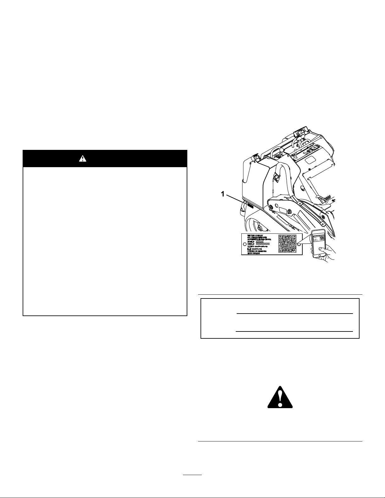
Wheneveryouneedservice,genuineToroparts,or
additionalinformation,contactanAuthorizedService
DealerorToroCustomerServiceandhavethemodel
andserialnumbersofyourproductready.Figure1
identiesthelocationofthemodelandserialnumbers
ontheproduct.Writethenumbersinthespace
provided.
Important:Withyourmobiledevice,youcan
scantheQRcodeontheserialnumberdecal(if
equipped)toaccesswarranty,parts,andother
productinformation.
g239557
Figure1
1.Modelandserialnumberlocation
ModelNo.
Introduction
Thismachineisacompacttoolcarrierintendedfor
useinvariousearthandmaterialsmovingactivitiesfor
landscapingandconstructionwork.Itisdesignedto
operateawidevarietyofattachmentseachofwhich
performaspecializedfunction.
Readthisinformationcarefullytolearnhowtooperate
andmaintainyourproductproperlyandtoavoid
injuryandproductdamage.Youareresponsiblefor
operatingtheproductproperlyandsafely .
YoumaycontactTorodirectlyatwww.T oro.com
forproductsafetyandoperationtrainingmaterials,
©2018—TheToro®Company
8111LyndaleAvenueSouth
Bloomington,MN55420
SerialNo.
Thismanualidentiespotentialhazardsandhas
safetymessagesidentiedbythesafety-alertsymbol
(Figure2),whichsignalsahazardthatmaycause
seriousinjuryordeathifyoudonotfollowthe
recommendedprecautions.
Figure2
Safety-alertsymbol
Thismanualuses2wordstohighlightinformation.
Importantcallsattentiontospecialmechanical
Contactusatwww.Toro.com.
2
g000502
PrintedintheUSA
AllRightsReserved
Page 3

informationandNoteemphasizesgeneralinformation
worthyofspecialattention.
Contents
Safety.......................................................................4
GeneralSafety...................................................4
SafetyandInstructionalDecals..........................5
ProductOverview...................................................10
Controls...........................................................10
MessageDisplay...........................................14
Specications..................................................15
Attachments/Accessories.................................15
BeforeOperation.................................................15
BeforeOperationSafety...................................15
AddingFuel......................................................16
PerformingDailyMaintenance..........................16
DuringOperation.................................................17
DuringOperationSafety...................................17
StartingtheEngine...........................................18
DrivingtheMachine..........................................18
ShuttingOfftheEngine.....................................19
UsingAttachments...........................................19
AfterOperation....................................................21
AfterOperationSafety......................................21
MovingaNon-FunctioningMachine..................21
TransportingtheMachine.................................21
LiftingtheMachine...........................................23
Maintenance...........................................................24
RecommendedMaintenanceSchedule(s)...........24
Pre-MaintenanceProcedures..............................25
MaintenanceSafety..........................................25
UsingtheCylinderLocks..................................25
AccessingInternalComponents.......................26
Lubrication..........................................................28
GreasingtheMachine.......................................28
EngineMaintenance...........................................29
EngineSafety...................................................29
ServicingtheAirCleaner..................................29
ServicingtheEngineOil....................................30
FuelSystemMaintenance...................................32
DrainingtheFuelFilter/WaterSeparator...........32
ReplacingtheFuelFilterCanisterand
In-LineFilter..................................................32
CheckingtheFuelLinesand
Connections..................................................33
BleedingtheFuelSystem.................................33
DrainingtheFuelT ank(s)..................................33
ElectricalSystemMaintenance...........................34
ElectricalSystemSafety...................................34
ServicingtheBattery.........................................34
ServicingtheFuses..........................................38
DriveSystemMaintenance..................................38
ServicingtheTracks.........................................38
CoolingSystemMaintenance..............................43
CoolingSystemSafety.....................................43
ServicingtheCoolingSystem...........................43
BrakeMaintenance.............................................44
TestingtheParkingBrake.................................44
ControlsSystemMaintenance.............................45
AdjustingtheControls.......................................45
HydraulicSystemMaintenance...........................45
HydraulicSystemSafety...................................45
HydraulicFluidSpecications...........................45
CheckingtheHydraulic-FluidLevel...................46
ReplacingtheHydraulicFilter...........................46
ChangingtheHydraulicFluid............................47
Cleaning..............................................................48
RemovingDebris..............................................48
CleaningtheChassis........................................48
Storage...................................................................49
StorageSafety..................................................49
Storage.............................................................49
Troubleshooting......................................................50
Schematics.............................................................54
3
Page 4

Safety
DANGER
Theremaybeburiedutilitylinesinthework
area.Diggingintothemmaycauseashock
oranexplosion.
Havethepropertyorworkareamarkedfor
buriedlinesanddonotdiginmarkedareas.
Contactyourlocalmarkingserviceorutility
companytohavethepropertymarked(for
example,intheUS,call811orinAustralia,
call1100forthenationwidemarkingservice).
GeneralSafety
Alwaysfollowallsafetyinstructionstoavoidserious
injuryordeath.Usingthisproductforpurposesother
thanitsintendedusecouldprovedangeroustoyou
andbystanders.
•Donotcarryaloadwiththearmsraised;always
carryloadsclosetotheground.
•Keepbystandersandpetsasafedistanceaway
fromthemachine.
•Stopthemachine,shutofftheengine,andremove
thekeybeforeservicing,fueling,orunclogging
themachine.
Improperlyusingormaintainingthismachinecan
resultininjury .T oreducethepotentialforinjury,
complywiththesesafetyinstructionsandalways
payattentiontothesafety-alertsymbol
meansCaution,Warning,orDanger—personalsafety
instruction.Failuretocomplywiththeseinstructions
mayresultinpersonalinjuryordeath.
Youcanndadditionalsafetyinformationwhere
neededthroughoutthismanual.
,which
•Slopesareamajorfactorrelatedtoloss-of-control
andtip-overaccidents,whichcanresultinsevere
injuryordeath.Operatingthemachineonany
slopeoruneventerrainrequiresextracaution.
•Operatethemachineupanddownslopeswith
theheavyendofthemachineuphillandtheload
closetotheground.Weightdistributionchanges
withattachments.Anemptybucketmakesthe
rearofthemachinetheheavyend,andafull
bucketmakesthefrontofthemachinetheheavy
end.Mostotherattachmentsmakethefrontofthe
machinetheheavyend.
•Havethepropertyorworkareamarkedforburied
linesandotherobjects,anddonotdiginmarked
areas.
•ReadandunderstandthecontentofthisOperator’s
Manualbeforestartingtheengine.
•Useyourfullattentionwhileoperatingthe
machine.Donotengageinanyactivitythat
causesdistractions;otherwise,injuryorproperty
damagemayoccur.
•Neverallowchildrenoruntrainedpeopleto
operatethemachine.
•Keepyourhandsandfeetawayfromthemoving
componentsandattachments.
•Donotoperatethemachinewithouttheguards
andothersafetyprotectivedevicesinplaceand
workingonthemachine.
4
Page 5
SafetyandInstructionalDecals
Safetydecalsandinstructionsareeasilyvisibletotheoperatorandarelocatednearanyarea
ofpotentialdanger.Replaceanydecalthatisdamagedormissing.
BatterySymbols
Someorallofthesesymbolsareonyourbattery .
1.Explosionhazard
2.Nore,opename,or
smoking
3.Causticliquid/chemical
burnhazard
4.Weareyeprotection.9.Flusheyesimmediately
5.ReadtheOperator's
Manual.
6.Keepbystandersasafe
distanceawayfromthe
battery.
7.Weareyeprotection;
explosivegasescan
causeblindnessandother
injuries.
8.Batteryacidcancause
blindnessorsevereburns.
withwaterandgetmedical
helpfast.
10.Containslead;donot
discard
decalbatterysymbols
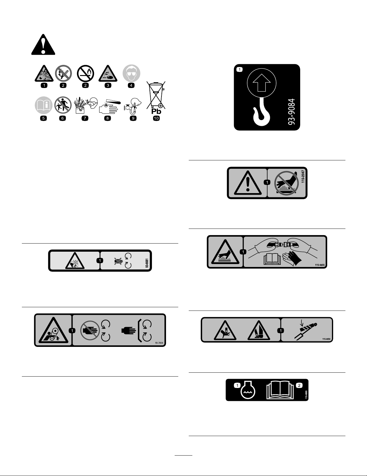
decal93-9084
93-9084
1.Liftpoint/Tie-downpoint
decal115-2047
115-2047
1.Warning—donottouchthehotsurface.
93-6681
1.Cutting/dismembermenthazard,fan—stayawayfrom
movingparts.
93-7814
1.Entanglementhazard,belt—stayawayfrommovingparts.
decal93-6681
115-4855
decal115-4855
1.Hotsurface/burnhazard—wearprotectivegloveswhen
handlingthehydrauliccouplersandreadtheOperator's
Manualforinformationonhandlinghydrauliccomponents.
decal93-7814
115-4858
decal115-4858
1.Crushinghazardofhandsorfeet—installthecylinderlock.
decal115-4865
115-4865
1.Enginecoolant
2.ReadtheOperator's
Manual.
5
Page 6
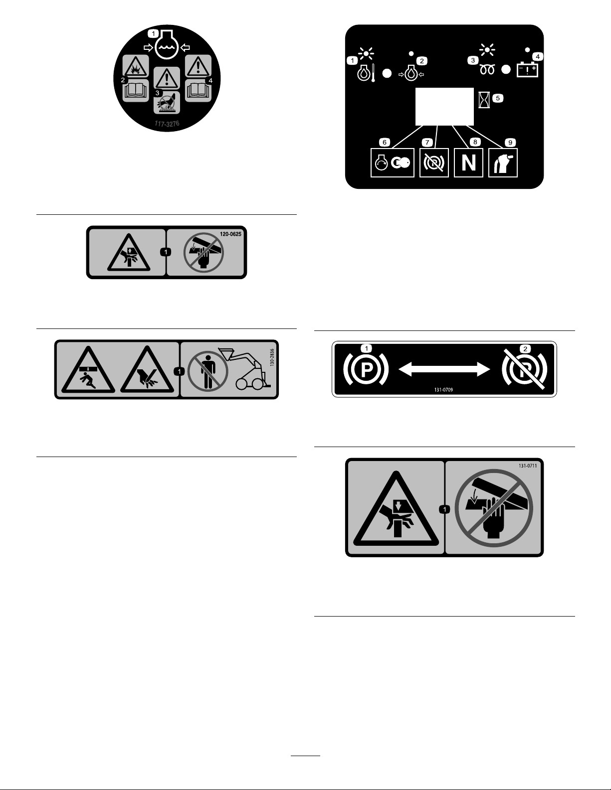
decal117-3276
117-3276
1.Enginecoolantunder
pressure
2.Explosionhazard—read
theOperator'sManual.
3.Warning—donottouchthe
hotsurface.
4.Warning—readthe
Operator'sManual.
120-0625
1.Pinchpoint,hand—keephandsaway.
130-2836
1.Crushinghazard;cuttinghazard—keepawayfromthe
attachmentandtheliftarm.
decal130-7637
130-7637
1.Blinking
light—engine-coolant
temperature
2.Steadylight—engine-oil
pressure
decal120-0625
3.Blinkinglight—glowplug8.Tractionneutral
4.Steadylight—battery
warning
5.Hourmeter
decal130-2836
6.Enginestart
7.Parkingbrakedisengaged
9.Auxiliaryleverneutral
decal131-0709
131-0709
1.Parkingbrake—engage2.Parkingbrake—disengage
131-0711
1.Crushinghazard—keepawayfrompinchpointsand
actuatingparts.
6
decal131-0711
Page 7
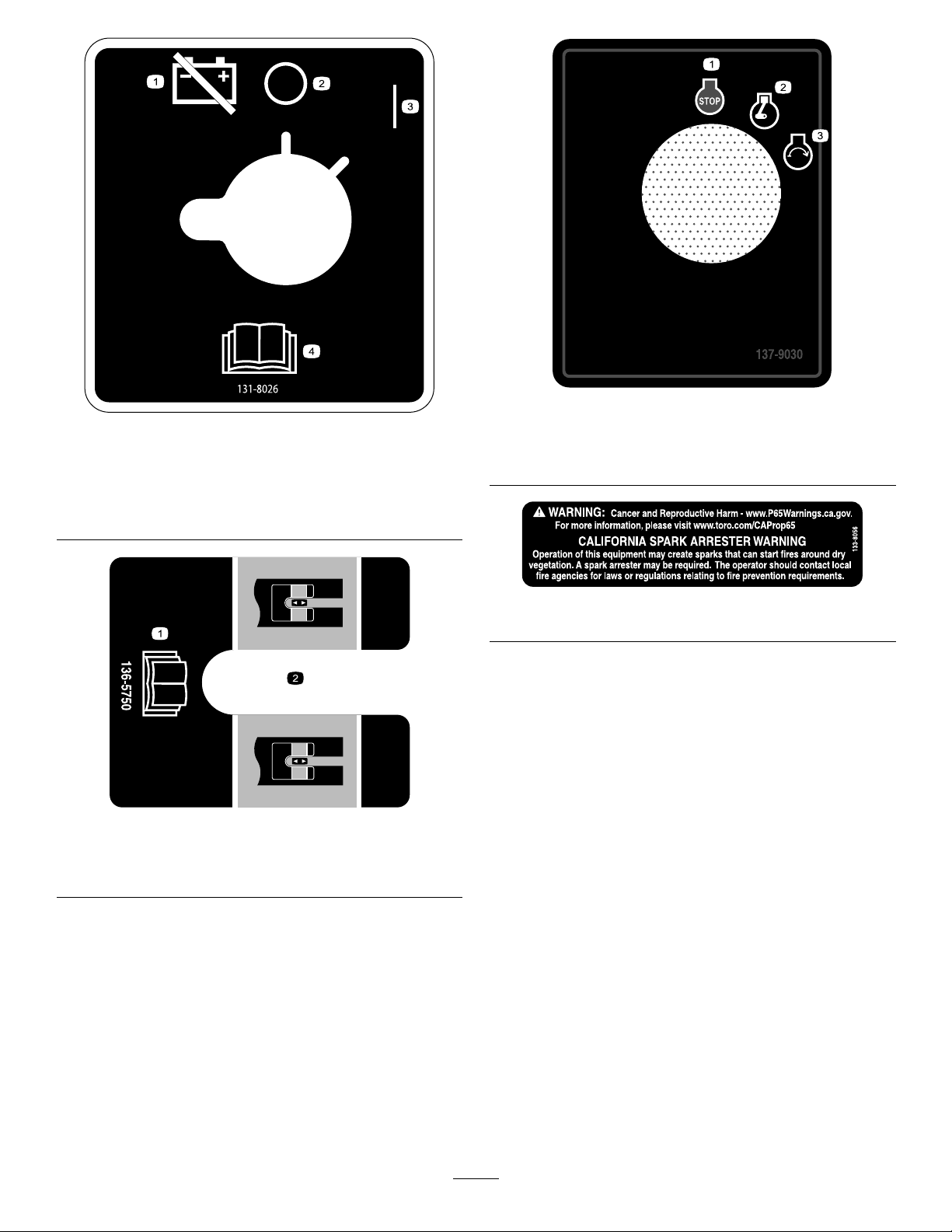
131-8026
1.Battery
power—disconnect
2.On4.ReadtheOperator's
3.Off
136-5750
Manual.
decal137-9030
decal131-8026
137-9030
1.Engine—stop3.Engine—start
2.Engine—run
decal133-8056
133-8056
decal136-5750
1.ReadtheOperator's
Manual.
2.Tensionblockguide
7
Page 8
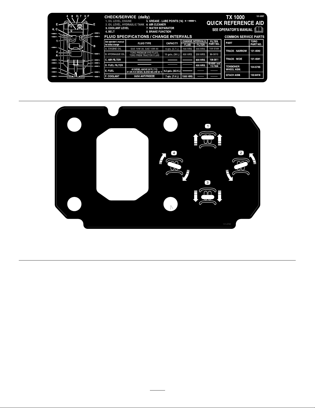
decal131-0597
131-0597
decal131-0708
131-0708
1.Moveforward
2.Turnright
3.Moverearward
4.Turnleft
8
Page 9

decal131-0710
131-0710
1.Warning—readtheOperator'sManual.7.Cutting/severinghazardofhandorfoot—waitforallmoving
partstostopbeforeservicing;keepawayfrommovingparts;
keepallguardsandshieldsinplace.
2.Warning—receivetrainingbeforeoperatingthemachine.
8.Explosionhazard;electrocutionhazard—callthelocalutilities
hotlinebeforebeginningworkinanarea.
3.Warning—wearhearingprotection.
9.Crushinghazard—keepawayfromtheattachmentwhen
operatingthemachine;keepbystandersawayfromthe
machine.
4.Warning—engagetheparkingbrake,lowertheattachmentto
theground,shutofftheengine,andremovethekeyfromthe
ignitionbeforeleavingthemachine.
10.Tippinghazard—alwaysmoveupordownslopeswith
theattachmentlowered;neverdriveonaslopewiththe
attachmentraised;alwaysoperatewiththeheavyenduphill;
alwayscarryloadslow;neverjerkthecontrollevers;use
asteady,evenmotion.
5.Electrocutionhazard,powerlines—checkforpowerlinesin
theareabeforeusingthemachine.
11.Tippinghazard—donotmakefastturns;alwayscheckbehind
youbeforereversingthemachine.
6.Crushinghazard—keepawayfrompinchpoints;read
theOperator'sManualbeforeservicingorperforming
maintenance.
136-5824
1.Powersocket7.Enginespeed
2.Hydraulicuid—slow8.Lower/oattheattachment.
3.Hydraulicuid—fast
9.Tilttheattachmentforward.
4.Hydraulicattachment—neutral10.Raisetheattachment.
5.Hydraulicattachment—forward
11.Tilttheattachmentrearward.
6.Hydraulicattachment—reverse12.Leverlock
9
decal136-5824
Page 10
ProductOverview
Controls
Becomefamiliarwithallthecontrols(Figure4)before
youstarttheengineandoperatethetractionunit.
ControlPanel
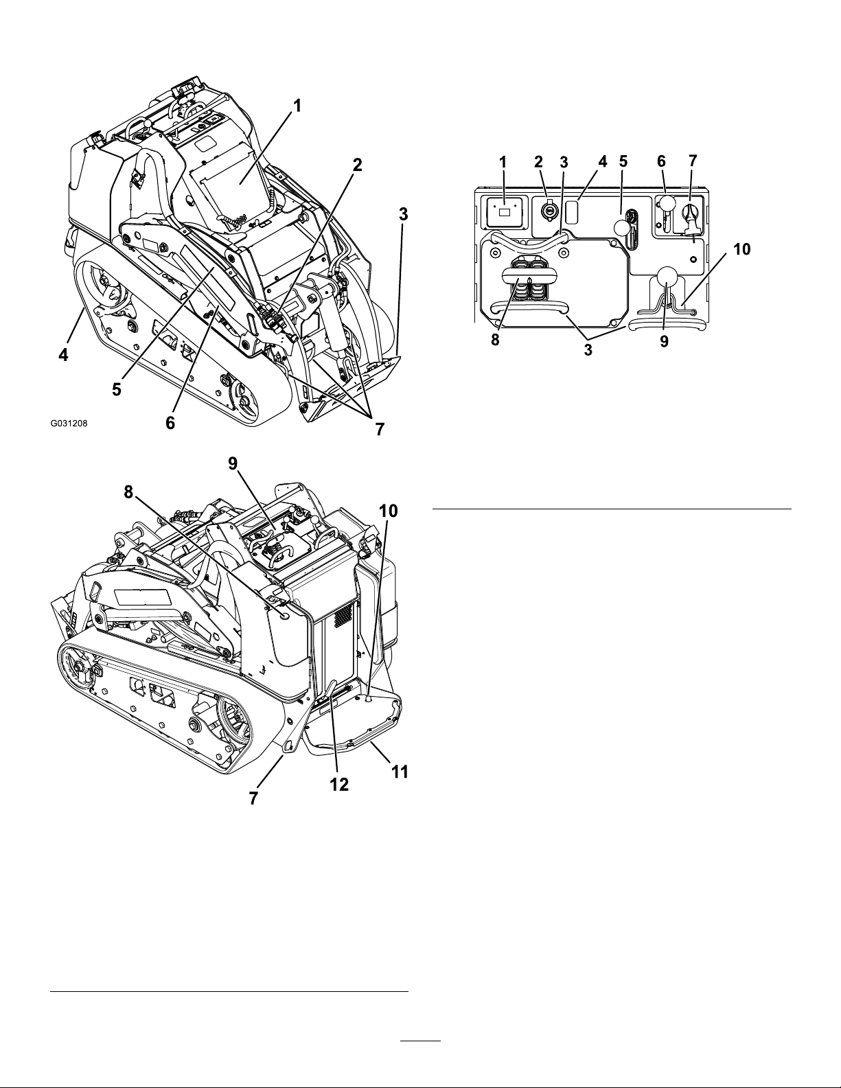
g259644
Figure4
1.Messagedisplay6.Throttlelever
2.Powersocket7.Keyswitch
g031208
3.Referencebar
4.Plug
5.Auxiliaryhydraulicslever
8.Tractioncontrol
9.Loader-arm/attachment-tilt
lever
10.Loaderlock
Figure3
1.Hood
2.Auxiliaryhydraulic
couplers
3.Mountplate
4.Track10.Auxiliaryhydraulicslock
5.Loaderarm
6.Liftcylinder
7.Tie-down/liftloop
8.Fuelgauge
9.Controlpanel
switch
11.Operatorplatform
12.Parkingbrake
KeySwitch
Thekeyswitch,usedtostartandshutofftheengine,
has3positions:OFF,RUN,andST ART.Referto
StartingtheEngine(page18).
ThrottleLever
Movethecontrolforwardtoincreasetheenginespeed
andrearwardtodecreasespeed.
ReferenceBar
Whendrivingthetractionunit,usethereferencebar
asahandleandaleveragepointforcontrollingthe
g259625
tractioncontrolandtheauxiliary-hydraulicslever.T o
ensuresmooth,controlledoperation,donottake
yourhandsoffthereferencebarswhileoperatingthe
machine.
10
Page 11
TractionControl
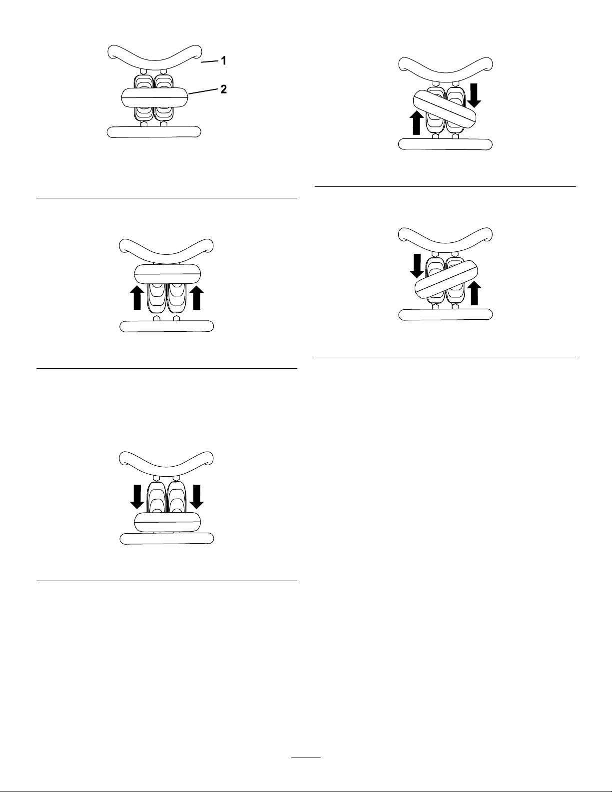
Figure5
1.Referencebar
2.Tractioncontrol
•Tomoveforward,movethetractioncontrolforward
(Figure6).
•Toturnright,rotatethetractioncontrolclockwise
(Figure8).
g259646
g259649
Figure8
•Toturnleft,rotatethetractioncontrol
counterclockwise(Figure9).
Figure6
•Tomoverearward,movethetractioncontrol
rearward(Figure7).
Important:Whenreversing,lookbehindyou
forobstructionsandkeepyourhandsonthe
referencebar.
Figure7
g259648
g259645
Figure9
•Tostopthemachine,releasethetractioncontrol
(Figure5).
Note:Thefartheryoumovethetractioncontrolin
anydirection,thefasterthemachinemovesinthat
direction.
g259647
11
Page 12
LoaderArm/Attachment-TiltLever
Loader-ValveLock
•Totilttheattachmentforward,slowlymovethe
levertotheright(Figure10).
•Totilttheattachmentrearward,slowlymovethe
levertotheleft(Figure10).
•Tolowertheloaderarms,slowlymovethelever
forward(Figure10).
•Toraisetheloaderarms,slowlymovethelever
rearward(Figure10).
•Tolowertheloaderarmstoadetent(oat)
position,pushtheleverfullyforward(Figure10).
Note:Thisallowsattachmentssuchastheleveler
andthehydraulicbladetofollowthecontoursof
theground(i.e.,oat)whengrading.
Theloader-valvelocksecurestheloader
arm/attachment-tiltleversothatyoucannotpushit
forward.Thishelpstoensurethatnooneaccidentally
lowerstheloaderarmsduringmaintenance.Secure
theloaderarmswiththelockanytimeyouneedto
shutoffthemachinewiththeloaderarmsraised.
Tosetthelock,liftuponitsothatitclearstheholein
thecontrolpanelandswingittotheleft,infrontof
theloader-armlever,pushingitdownintothelocked
position(Figure11).
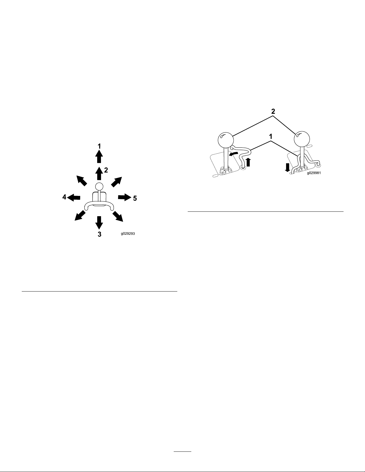
Figure11
1.Loaderarm/attachment-tilt
lever
2.Loader-valvelock
g029981
Figure10
1.Detent(oat)position
2.Lowertheloaderarms.5.Tilttheattachment
3.Raisetheloaderarms.
4.Tilttheattachment
rearward.
forward.
Bymovingthelevertoanintermediateposition(e.g.,
forwardandleft),youcanmovetheloaderarmsand
tilttheattachmentatthesametime.
Loader-Control-ReferenceBar
g029293
Theloader-control-referencebarhelpsstabilizeyour
handwhileoperatingtheloaderarm/attachment-tilt
lever(Figure3).
12
Page 13

Auxiliary-HydraulicsLever
Parking-BrakeLever
•Tooperateahydraulicattachmentintheforward
direction,movetheauxiliary-hydraulicslever
forward(Figure12).
•Tooperateahydraulicattachmentinthereverse
direction,movetheauxiliary-hydraulicslever
rearward(Figure12).
Note:IfyoureleasetheleverwhileintheFORWARD
orREVERSEposition,theleverautomaticallyreturnsto
theNEUTRALposition(Figure12).
Figure12
1.Forward-owhydraulics
2.Reverse-owhydraulics
3.Neutral
•Toengagetheparkingbrake,rotatetheleverto
left(Figure14).
Note:Thetractionunitmayrollslightlybeforethe
brakesengageinthedrivesprocket.
•Toreleasethebrake,rotatethebrakelevertothe
right.
Note:Y oumayneedtoadjustthetractioncontrol
toreleasethebrakepinsandrotatethelever.
g029294
Figure14
g030721
Auxiliary-HydraulicsLockSwitch
Useyourrightfoottopressthe
auxiliary-hydraulics-lockswitchtocontinuethe
forwardorreverseowoftheauxiliaryhydraulicsand
freeyourhandforothercontrols(Figure13).
Figure13
1.Auxiliary-hydraulicslockswitch
FuelGauge
Thisgaugemeasurestheamountoffuelinthefuel
tank(s).
g205234
13
Page 14

MessageDisplay
Battery-ChargeLight
Engine-Coolant-TemperatureLight
Iftheenginecoolantbecomestoohot,thelighton
theleftashesandthehornsounds(Figure15).If
thishappens,disengagetheauxiliaryhydraulicsand
letthemachinerunathighidletoallowthecooling
systemtocoolthemachine.Checkthecoolantlevel
whentheenginehasfullycooled.
Important:Donotshutofftheengine,asthis
maycausethemachinetooverheat.
Figure15
Engine-Oil-PressureLight
Iftheengine-oil-pressurebecomestoolow,thelight
ontheleftilluminatessteadily(Figure16).Ifthis
happens,shutofftheengineimmediatelyandcheck
theoillevel.Ifitislow,addoilandlookforpossible
leaks.
Ifthebatterychargebecomestoolow,thelightonthe
rightilluminatessteadily(Figure18).Ifthishappens,
shutofftheengineandchargeorreplacethebattery .
RefertoServicingtheBattery(page34).
g029667
Figure18
HourMeter
Thehourmeterdisplaysthenumberofhoursof
g029666
operationthathavebeenloggedonthetractionunit
andthefollowingindicators:
•Enginestart—displayswhenyoustarttheengine
g029974
Figure19
•Parkingbrake—displayswhenyoudisengagethe
parkingbrake
Figure16
Glow-PlugLight
Thelightontherightasheswhiletheglowplugsare
chargedandwarmingtheengine(Figure17).
Figure17
g029665
Figure20
g030520
•Tractionneutral—displayswhenthetraction
controlisintheNEUTRALposition
g029211
Figure21
g029668
•Auxiliaryleverneutral—displayswhentheauxiliary
leverisintheNEUTRALposition
g029975
Figure22
14
Page 15

Specications
Note:Specicationsanddesignaresubjectto
changewithoutnotice.
Model22327
Width
Length
Height
Weight
Operatingcapacity(with75kg(165lb)
operatorandstandardbucket)
Tippingcapacity(with75kg(165lb)
operatorandstandardbucket)
Wheelbase
Dumpheight(withstandardbucket)155cm(61inches)
Reach—fullyraised(withstandard
bucket)
Heighttohingepin(withstandard
bucketinhighestposition)
Model22328
Width
Length
Height
Weight
Operatingcapacity(with75kg(165lb)
operatorandstandardbucket)
Tippingcapacity(with75kg(165lb)
operatorandstandardbucket)
Wheelbase
Dumpheight(withstandardbucket)155cm(61inches)
Reach—fullyraised(withstandard
bucket)
Heighttohingepin(withstandard
bucketinhighestposition)
Attachments/Accessories
AselectionofT oroapprovedattachmentsand
accessoriesisavailableforusewiththemachine
toenhanceandexpanditscapabilities.Contact
yourAuthorizedServiceDealerorauthorizedT oro
distributororgotowww.Toro.comforalistofall
approvedattachmentsandaccessories.
Toensureoptimumperformanceandcontinuedsafety
certicationofthemachine,useonlygenuineT oro
replacementpartsandaccessories.Replacement
partsandaccessoriesmadebyothermanufacturers
couldbedangerous,andsuchusecouldvoidthe
productwarranty.
85cm(33inches)
256cm(101inches)
138cm(54inches)
1234kg(2,720lb)
454kg(1,000lb)
1296kg(2,857lb)
104cm(41inches)
62cm(25inches)
206cm(81inches)
103cm(41inches)
256cm(101inches)
138cm(54inches)
1297kg(2,860lb)
454kg(1,000lb)
1296kg(2,857lb)
104cm(41inches)
62cm(25inches)
206cm(81inches)
Operation
Note:Determinetheleftandrightsidesofthe
machinefromthenormaloperatingposition.
BeforeOperation
BeforeOperationSafety
GeneralSafety
•Neverallowchildrenoruntrainedpeopleto
operateorservicethemachine.Localregulations
mayrestricttheageorrequirecertiedtrainingof
theoperator.Theownerisresponsiblefortraining
alloperatorsandmechanics.
•Becomefamiliarwiththesafeoperationofthe
equipment,operatorcontrols,andsafetydecals.
•Knowhowtostopthemachineandshutoffthe
enginequickly.
•Checkthattheoperator'spresencecontrols,safety
switches,andshieldsareattachedandfunctioning
properly.Donotoperatethemachineunlessthey
arefunctioningproperly.
•Locatethepinch-pointareasmarkedonthe
machineandattachments;keepyourhandsand
feetawayfromtheseareas.
•Beforeoperatingthemachinewithanattachment,
ensurethattheattachmentisproperlyinstalled
andthatitisagenuineT oroattachment.Readall
theattachmentmanuals.
•Evaluatetheterraintodeterminewhataccessories
andattachmentsyouneedtoproperlyandsafely
performthejob.
•Havethepropertyorworkareamarkedforburied
linesandotherobjects,anddonotdiginmarked
areas;notethelocationofunmarkedobjectsand
structures,suchasundergroundstoragetanks,
wells,andsepticsystems.
•Inspecttheareawhereyouwillusetheequipment
andremovealldebris.
•Ensurethattheareaisclearofbystandersbefore
operatingthemachine.Stopthemachineif
anyoneentersthearea.
FuelSafety
•Useextracarewhenhandlingfuel.Itisammable
anditsvaporsareexplosive.
•Extinguishallcigarettes,cigars,pipes,andother
sourcesofignition.
•Useonlyanapprovedfuelcontainer.
•Donotremovethefuelcaporllthefueltank
whiletheengineisrunningorhot.
15
Page 16

•Donotaddordrainfuelinanenclosedspace.
•Donotstorethemachineorfuelcontainerwhere
thereisanopename,spark,orpilotlight,such
asonawaterheaterorotherappliance.
FillingtheFuelTanks
Fueltankcapacity:41L(11USgallons)
FillthefueltanksasshowninFigure23.
•Ifyouspillfuel,donotattempttostarttheengine;
avoidcreatinganysourceofignitionuntilthefuel
vaporshavedissipated.
AddingFuel
RecommendedFuel
Useonlyclean,freshdieselfuelorbiodieselfuelswith
low(<500ppm)orultralow(<15ppm)sulfurcontent.
Theminimumcetaneratingshouldbe40.Purchase
fuelinquantitiesthatyoucanusewithin180daysto
ensurefuelfreshness.
Usesummer-gradedieselfuel(No.2-D)at
temperaturesabove-7°C(20°F)andwintergrade
(No.1-DorNo.1-D/2-Dblend)belowthat
temperature.Usingwinter-gradefuelatlower
temperaturesprovideslowerashpointandcoldow
characteristics,whicheasesstartingandreducesfuel
lterplugging.
Usingsummer-gradefuelabove-7°C(20°F)
contributestowardlongerfuelpumplifeandincreased
powercomparedtowinter-gradefuel.
Note:Thefuel-tankcapsclickwhenyouclosethem
securely.Usethebracketstolockthefueltanks.
Important:Donotusekeroseneorgasoline
insteadofdieselfuel.Failuretoobservethis
cautionwilldamagetheengine.
BiodieselReady
Thismachinecanalsouseabiodieselblendedfuel
ofuptoB20(20%biodiesel,80%petrodiesel).The
petrodieselportionshouldbeloworultralowsulfur.
Observethefollowingprecautions:
•Thebiodieselportionofthefuelmustmeet
specicationASTMD6751orEN14214.
•TheblendedfuelcompositionshouldmeetASTM
D975orEN590.
•Paintedsurfacesmaybedamagedbybiodiesel
blends.
•UseB5(biodieselcontentof5%)orlesserblends
incoldweather.
•Monitorseals,hoses,gasketsincontactwithfuel
astheymaydegradeovertime.
•Fuellterpluggingmayoccurforatimeafter
convertingtobiodieselblends.
g029669
Figure23
PerformingDaily Maintenance
Beforestartingthemachineeachday ,performthe
EachUse/DailyprocedureslistedintheMaintenance
(page24).
Important:Checkthehydraulic-uidlevel
andbleedthefuelsystembeforestartingthe
engineforthersttime;refertoCheckingthe
Hydraulic-FluidLevel(page46)andBleedingthe
FuelSystem(page33).
•Contactyourdistributorformoreinformationon
biodiesel.
16
Page 17

DuringOperation
DuringOperationSafety
GeneralSafety
•Donotcarryaloadwiththearmsraised.Always
carryloadsclosetotheground.
•Donotexceedtheratedoperatingcapacity,asthe
machinemaybecomeunstable,whichmayresult
inlossofcontrol.
•UseonlyToro-approvedattachmentsand
accessories.Attachmentscanchangethestability
andtheoperatingcharacteristicsofthemachine.
•Formachineswithaplatform:
–Lowertheloaderarmsbeforesteppingoffthe
platform.
–Donottrytostabilizethemachinebyputting
yourfootontheground.Ifyoulosecontrolof
themachine,stepofftheplatformandaway
fromthemachine.
–Donotplaceyourfeetundertheplatform.
–Donotmovethemachineunlessyouare
standingwithbothfeetontheplatformandyour
handsareholdingontothereferencebars.
•Useyourfullattentionwhileoperatingthe
machine.Donotengageinanyactivitythat
causesdistractions;otherwise,injuryorproperty
damagemayoccur.
•Lookbehindanddownbeforebackingupto
ensurethatthepathisclear.
•Neverjerkthecontrols;useasteadymotion.
•Theowner/usercanpreventandisresponsible
foraccidentsthatmaycausepersonalinjuryor
propertydamage.
•Wearappropriateclothingincludinggloves,eye
protection,longpants,substantialslip-resistant
footwear,andhearingprotection.Tiebacklong
hairanddonotwearlooseclothingorloose
jewelry.
•Donotoperatethemachinewhenyouaretired,ill,
orundertheinuenceofalcoholordrugs.
•Nevercarrypassengersandkeeppetsand
bystandersawayfromthemachine
•Operatethemachineonlyingoodlight,keeping
awayfromholesandhiddenhazards.
•Ensurethatallthedrivesareinneutralandengage
theparkingbrake(ifequipped)beforestartingthe
engine.Starttheengineonlyfromtheoperator's
position.
•Usecarewhenapproachingblindcorners,shrubs,
trees,orotherobjectsthatmayobscurevision.
•Slowdownandusecautionwhenmakingturns
andcrossingroadsandsidewalks.Watchfor
trafc.
•Stoptheattachmentwhenyouarenotworking.
•Stopthemachine,turnofftheengine,remove
thekey,andinspectthemachineifyoustrike
anobject.Makeanynecessaryrepairsbefore
resumingoperation.
•Neverrunanengineinanenclosedarea.
•Neverleavearunningmachineunattended.
•Beforeleavingtheoperatingposition,dothe
following:
–Parkthemachineonalevelsurface.
–Lowertheloaderarmsanddisengagethe
auxiliaryhydraulics.
–Engagetheparkingbrake(ifequipped).
–Shutofftheengineandremovethekey .
•Donotoperatethemachinewhenthereistherisk
oflightning.
•Operatethemachineonlyinareaswherethereis
sufcientclearanceforyoutosafelymaneuver.
Beawareofobstaclesincloseproximitytoyou.
Failuretomaintainadequatedistancefromtrees,
walls,andotherbarriersmayresultininjuryasthe
machinebacksupduringoperationifyouarenot
attentivetothesurroundings.
•Checkforoverheadclearance(i.e.,electrical
wires,branches,anddoorways)beforedriving
underanyobjectsanddonotcontactthem.
•Donotoverlltheattachmentandalwayskeepthe
loadlevelwhenraisingtheloaderarms.Itemsin
theattachmentcouldfallandcauseinjury.
SlopeSafety
•Operatethemachineupanddownslopeswith
theheavyendofthemachineuphill.Weight
distributionchangeswithattachments.Anempty
bucketmakestherearofthemachinetheheavy
end,andafullbucketmakesthefrontofthe
machinetheheavyend.Mostotherattachments
makethefrontofmachinetheheavyend.
•Raisingtheloaderarmsonaslopeaffectsthe
stabilityofthemachine.Keeptheloaderarmsin
theloweredpositionwhenonslopes.
•Slopesareamajorfactorrelatedtolossofcontrol
andtip-overaccidents,whichcanresultinsevere
injuryordeath.Operatingthemachineonany
slopeoruneventerrainrequiresextracaution.
•Establishyourownproceduresandrulesfor
operatingonslopes.Theseproceduresmust
includesurveyingthesitetodeterminewhich
slopesaresafeformachineoperation.Always
17
Page 18

usecommonsenseandgoodjudgmentwhen
performingthissurvey.
•Slowdownanduseextracareonhillsides.Ground
conditionscanaffectthestabilityofthemachine.
•Avoidstartingorstoppingonaslope.Ifthe
machinelosestraction,proceedslowly,straight
downtheslope.
•Avoidturningonslopes.Ifyoumustturn,turn
slowlyandkeeptheheavyendofthemachine
uphill.
•Keepallmovementsonslopesslowandgradual.
Donotmakesuddenchangesinspeedor
direction.
•Ifyoufeeluneasyoperatingthemachineona
slope,donotdoit.
•Watchforholes,ruts,orbumps,asuneventerrain
couldoverturnthemachine.Tallgrasscanhide
obstacles.
•Usecautionwhenoperatingonwetsurfaces.
Reducedtractioncouldcausesliding.
•Donotoperatethemachineneardrop-offs,
ditches,embankments,orbodiesofwater.The
machinecouldsuddenlyrolloverifawheelor
trackgoesovertheedgeortheedgecavesin.
Maintainasafedistancebetweenthemachine
andanyhazard.
•Donotremoveoraddattachmentsonaslope.
•Donotparkthemachineonahillsideorslope.
StartingtheEngine
1.Ensurethatthebattery-disconnectswitchisin
theONposition.
2.Ensurethattheauxiliary-hydraulicsleverand
traction-controlareintheNEUTRALposition.
3.Movethethrottlelevermidwaybetweenthe
SLOWandFASTpositions.
4.Insertthekeyintothekeyswitchandturnitto
theONposition.
5.Waitfortheglow-plugindicatorlighttostop
blinking.
6.TurnthekeytotheST ARTposition.Whenthe
enginesstarts,releasethekey .
Important:Donotengagethestarterfor
morethan10secondsatatime.Iftheengine
failstostart,wait30secondsforthestarter
tocooldownbetweenattempts.Failureto
followtheseinstructionscouldburnoutthe
startermotor.
7.MovethethrottlelevertotheFASTposition.
Important:Runningtheengineathigh
speedswhenthehydraulicsystemiscold
(i.e.,whentheairtemperatureisator
belowfreezing)coulddamagethehydraulic
system.Whenstartingtheengineincold
conditions,allowittoruninthemiddle
throttlepositionfor2to5minutesbefore
movingthethrottletotheFASTposition.
Note:Iftheoutdoortemperatureisbelow
freezing,storethetractionunitinagarageto
keepitwarmerandtoaidinstarting.
DrivingtheMachine
Usethetractioncontroltomovethemachine.The
fartheryoumovethetractioncontrolinanydirection,
thefasterthemachinemovesinthatdirection.
Releasethetractioncontroltostopthemachine.
Thethrottlecontrolregulatestheenginespeedas
measuredinrpm(revolutionsperminute).Placethe
throttleleverintheFASTpositionforbestperformance.
Youcan,however,usethethrottlepositiontooperate
atslowerspeeds.
18
Page 19

ShuttingOfftheEngine
1.Parkthemachineonalevelsurface,engage
theparkingbrake(ifequipped),andlowerthe
loaderarms.
2.Ensurethattheauxiliaryhydraulicsleverisin
theNEUTRALposition.
3.MovethethrottlelevertotheSLOWposition.
4.Iftheenginehasbeenworkinghardorishot,let
itidleforaminutebeforeturningthekeyswitch
totheOFFposition.
g003710
Figure24
Note:Thishelpstocooltheenginebeforeyou
shutitoff.Inanemergency ,youcanshutoff
theengineimmediately.
5.TurnthekeyswitchtotheOFFpositionand
removethekey.
CAUTION
Achildoruntrainedbystandercouldattempt
tooperatethetractionunitandbeinjured.
Removethekeyfromthekeyswitchwhen
leavingthetractionunit,evenifjustforafew
seconds.
UsingAttachments
InstallinganAttachment
Important:UseonlyToro-approvedattachments.
Attachmentscanchangethestabilityandthe
operatingcharacteristicsofthemachine.The
warrantyofthemachinemaybevoidedifyouuse
themachinewithunapprovedattachments.
1.Mountplate2.Receiverplate
5.Raisetheloaderarmswhiletiltingbackthe
mountplateatthesametime.
Important:Raisetheattachmentenoughto
clearthegroundandtiltthemountplateall
thewayback.
6.Shutofftheengineandremovethekey.
7.Engagethequick-attachpins,ensuringthatthey
arefullyseatedinthemountplate(Figure25).
Important:Ifthepinsdonotrotatetothe
engagedposition,themountplateisnot
fullyalignedwiththeholesintheattachment
receiverplate.Checkthereceiverplateand
cleanitifnecessary.
Important:Beforeinstallingtheattachment,
ensurethatthemountplatesarefreeofanydirtor
debrisandthatthepinsrotatefreely.Ifthepins
donotrotatefreely,greasethem.
1.Positiontheattachmentonalevelsurfacewith
enoughspacebehindittoaccommodatethe
machine.
2.Starttheengine.
3.Tilttheattachmentmountplateforward.
4.Positionthemountplateintotheupperlipofthe
attachmentreceiverplate(Figure24).
19
Page 20

1.Quick-attachpins
(engagedposition)
2.Disengagedposition
Figure25
3.Engagedposition
ConnectingtheHydraulicHoses
WARNING
Hydraulicuidescapingunderpressurecan
penetrateskinandcauseinjury.Fluidinjected
intotheskinmustbesurgicallyremoved
withinafewhoursbyadoctorfamiliarwith
thisformofinjury;otherwise,gangrenemay
result.
•Ensurethatallhydraulic-uidhoses
andlinesareingoodconditionandall
hydraulicconnectionsandttingsaretight
beforeapplyingpressuretothehydraulic
system.
•Keepyourbodyandhandsawayfrom
pinholeleaksornozzlesthateject
high-pressurehydraulicuid.
•Usecardboardorpapertondhydraulic
leaks;neveruseyourhands.
g003711
CAUTION
Hydrauliccouplers,hydrauliclines/valves,
andhydraulicuidmaybehot.Ifyoucontact
hotcomponents,youmaybeburned.
WARNING
Ifyoudonotfullyseatthequick-attach
pinsthroughtheattachmentmountplate,
theattachmentcouldfalloffthemachine,
crushingyouorbystanders.
Ensurethatthequick-attachpinsarefully
seatedintheattachmentmountplate.
•Weargloveswhenoperatingthehydraulic
couplers.
•Allowthemachinetocoolbeforetouching
hydrauliccomponents.
•Donottouchhydraulicuidspills.
Iftheattachmentrequireshydraulicsforoperation,
connectthehydraulichosesasfollows:
1.Shutofftheengineandremovethekey.
2.Movetheauxiliary-hydraulicsleverforward,
backward,andbacktotheNEUTRALpositionto
relievepressureatthehydrauliccouplers.
3.Removetheprotectivecoversfromthehydraulic
connectorsonthemachine.
4.Ensurethatallforeignmatteriscleanedfrom
thehydraulicconnectors.
5.Pushtheattachmentmaleconnectorintothe
femaleconnectoronthemachine.
Note:Whenyouconnecttheattachmentmale
connectorrst,yourelieveanypressurebuilt
upintheattachment.
6.Pushtheattachmentfemaleconnectorontothe
maleconnectoronthemachine.
7.Conrmthattheconnectionissecurebypulling
onthehoses.
20
Page 21

RemovinganAttachment
1.Parkthemachineonalevelsurface.
2.Lowertheattachmenttotheground.
3.Shutofftheengineandremovethekey.
4.Disengagethequick-attachpinsbyturningthem
totheoutside.
5.Iftheattachmentuseshydraulics,movethe
auxiliary-hydraulicsleverforward,backward,
andbacktotheNEUTRALpositiontorelieve
pressureatthehydrauliccouplers.
6.Iftheattachmentuseshydraulics,slidethe
collarsbackonthehydrauliccouplersand
disconnectthem.
Important:Connecttheattachmenthoses
togethertopreventhydraulicsystem
contaminationduringstorage.
7.Installtheprotectivecoversontothehydraulic
couplersonthemachine.
8.Starttheengine,tiltthemountplateforward,and
backthemachineawayfromtheattachment.
4.Usingawrench,turnthetowvalvesonthe
hydraulicpumpstwicecounterclockwise(Figure
26).
g031210
AfterOperation
AfterOperationSafety
•Shutofftheengine,removethekey ,waitforall
movementtostop,andallowthemachinetocool
beforeadjusting,cleaning,storing,orservicingit.
•Cleandebrisfromtheattachments,drives,
mufers,andenginetohelppreventres.Clean
upoilorfuelspills.
•Keepallpartsingoodworkingconditionandall
hardwaretightened.
•Donottouchpartsthatmaybehotfromoperation.
Allowthemtocoolbeforeattemptingtomaintain,
adjust,orservicethemachine.
•Usecarewhenloadingorunloadingthemachine
intoatrailerortruck.
MovingaNon-Functioning Machine
Important:Donottoworpullthemachine
withoutrstopeningthetowvalves,oryouwill
damagethehydraulicsystem.
1.Shutofftheengineandremovethekey.
2.Openthehoodandsecurethehoodprop.
3.Removethesidescreens;refertoRemovingthe
SideScreens(page27).
g031211
Figure26
1.Towvalve
5.Towthemachineasrequired.
6.Afterrepairingthemachine,closethetowvalves
beforeoperatingit.
TransportingtheMachine
Useaheavy-dutytrailerortrucktotransportthe
machine.Useafull-widthramp.Ensurethatthetrailer
ortruckhasallthenecessarybrakes,lighting,and
markingasrequiredbylaw.Pleasecarefullyreadall
thesafetyinstructions.Knowingthisinformationcould
helpyouorbystandersavoidinjury.Refertoyour
localordinancesfortrailerandtie-downrequirements.
WARNING
Drivingonthestreetorroadwaywithout
turnsignals,lights,reectivemarkings,ora
slow-moving-vehicleemblemisdangerous
andcanleadtoaccidentscausingpersonal
injury.
Donotdrivethemachineonapublicstreet
orroadway.
21
Page 22

SelectingaTrailer
LoadingtheMachine
WARNING
Loadingamachineontoatrailerortruck
increasesthepossibilityoftip-overandcould
causeseriousinjuryordeath(Figure27).
•Useonlyafull-widthramp;donotuse
individualrampsforeachsideofthe
machine.
•Ensurethatthelengthoframpisatleast4
timesaslongastheheightofthetraileror
truckbedtotheground.Thisensuresthat
rampangledoesnotexceed15degreeson
atground.
WARNING
Loadingamachineontoatrailerortruck
increasesthepossibilityoftip-overandcould
causeseriousinjuryordeath.
•Useextremecautionwhenoperatinga
machineonaramp.
•Loadandunloadthemachinewiththe
heavyenduptheramp.
•Avoidsuddenaccelerationordeceleration
whiledrivingthemachineonarampas
thiscouldcausealossofcontrolora
tip-oversituation.
1.Ifusingatrailer,connectittothetowingvehicle
andconnectthesafetychains.
2.Ifapplicable,connectthetrailerbrakes.
3.Lowertheramp(Figure27).
4.Lowertheloaderarms.
5.Loadthemachineontothetrailerwiththeheavy
enduptheramp,carryingloadslow(Figure28).
•Ifthemachinehasafullload-carrying
attachment(e.g.,bucketoradjustableforks)
oranon-load-carryingattachment(e.g.,
stumpgrinder),drivethemachineforward
uptheramp.
•Ifthemachinehasanemptyload-carrying
attachmentornoattachment,backthe
machineuptheramp.
1.Full-widthrampinstowed
position
2.Rampisatleast4times
aslongastheheightof
thetrailerortruckbedto
theground
Figure27
3.H=heightofthetraileror
truckbedtotheground
4.Trailer
g229507
g204457
Figure28
1.Machinewithfull
attachmentor
non-load-carrying
attachment—drivethe
machineforwardupthe
ramp.
2.Machinewithemptyor
noattachment—backthe
machineuptheramp.
6.Lowertheloaderarmsallthewaydown.
7.Shutofftheengine,removethekey,andengage
theparkingbrake.
8.Usethemetaltie-downloopsonthemachine
tosecurelyfastenthemachinetothetraileror
truckwithstraps,chains,cable,orropes(Figure
29).Refertolocalregulationsfortie-down
requirements.
22
Page 23

Figure29
1.Tie-downloops
UnloadingtheMachine
1.Lowertheramp(Figure28).
2.Unloadthemachinefromthetrailerwiththe
heavyenduptheramp,carryingloadslow
(Figure30).
•Ifthemachinehasafullload-carrying
attachment(e.g.,bucketoradjustableforks)
oranon-load-carryingattachment(e.g.,
stumpgrinder),backitdowntheramp.
•Ifthemachinehasanemptyload-carrying
attachmentornoattachment,driveitforward
downtheramp.
g031331
Figure30
1.Machinewithfull
attachmentor
non-load-carrying
attachment—backthe
machinedowntheramp.
2.Machinewithemptyor
noattachment—drivethe
machineforwarddownthe
ramp.
LiftingtheMachine
Youcanliftthemachineusingthetie-down/liftloops
asliftpoints;refertoFigure29.
g204458
23
Page 24

Maintenance
Note:Determinetheleftandrightsidesofthemachinefromthenormaloperatingposition.
Important:Refertoyourengineowner’smanualforadditionalmaintenanceprocedures.
CAUTION
Ifyouleavethekeyintheswitch,someonecouldaccidentlystarttheengineandseriously
injureyouorotherbystanders.
Removethekeyfromtheswitchbeforeyouperformanymaintenance.
RecommendedMaintenanceSchedule(s)
MaintenanceService
Interval
Aftertherst8hours
Aftertherst50hours
Beforeeachuseordaily
Every25hours
Every50hours
MaintenanceProcedure
•Checkandadjustthetracktension.
•Replacethehydrauliclter.
•Changetheengineoilandlter.
•Greasethemachine.(Greaseimmediatelyaftereverywashing.)
•Checktheair-lter-serviceindicator.
•Checktheengine-oillevel.
•Drainwaterandothercontaminantsfromthefuellter/waterseparator.
•Cleanthetracks.
•Checkthetracksforexcessivewearandpropertension.
•Cleanthescreen,oilcooler,andfrontoftheradiator(moreoftenindirtyordusty
conditions).
•Checkthecoolantlevelintheexpansiontank.
•Checkandcleantheradiatorscreen
•Testtheparkingbrake.
•Removedebrisfromthemachine.
•Checkforloosefasteners.
•Removetheair-cleanercover,cleanoutdebris,andchecktheair-lter-service
indicator.
•Checkthehydraulic-uidlevel.
•Checkthebatterycondition.
•Checkandadjustthetracktension.
Every100hours
Every200hours
Every400hours
Every500hours
Every1,500hours
•Changetheengineoil.(Servicemorefrequentlyifconditionsareextremelydusty
orsandy.)
•Checkthecoolingsystemhoses.
•Checkthehydrauliclinesforleaks,loosettings,kinkedlines,loosemounting
supports,wear,weather,andchemicaldeterioration.
•Checkfordirtbuildupinthechassis.
•Checkthealternator/fanbelttension(refertotheengineowner’smanualfor
instructions).
•Changetheoillter.(Servicemorefrequentlyifconditionsareextremelydusty
orsandy.)
•Replacethehydrauliclter.
•Replacethefuelltercanisterandin-linelter.
•Checkthefuellinesandconnectionsfordeterioration,damage,orlooseconnections.
•Changethehydraulicuid.
•Replacethealternator/fanbelt(refertotheengineowner’smanualforinstructions).
•Replaceallmovinghydraulichoses.
24
Page 25

MaintenanceService
Interval
MaintenanceProcedure
Yearly
Yearlyorbeforestorage
Every2years
•Changetheenginecoolant(AuthorizedServiceDealeronly).
•Changetheenginecoolant.
•Checkandadjustthetracktension.
•Touchupchippedpaint.
•Drainandcleanthefueltank(s)—AuthorizedServiceDealeronly .
•Replaceallmovinghydraulichoses.
Pre-Maintenance
Procedures
MaintenanceSafety
•Parkthemachineonalevelsurface,disengage
theauxiliaryhydraulics,lowertheattachment,
engagetheparkingbrake(ifequipped),shut
offtheengine,andremovethekey .Waitforall
movementtostopandallowthemachinetocool
beforeadjusting,cleaning,storing,orrepairingit.
•Cleanupoilorfuelspills.
•Donotallowuntrainedpersonneltoservicethe
machine.
•Usejackstandstosupportthecomponentswhen
required.
•Carefullyreleasepressurefromcomponentswith
storedenergy.
UsingtheCylinderLocks
WARNING
Theloaderarmsmaylowerwhenintheraised
position,crushinganyoneunderthem.
Installthecylinderlock(s)beforeperforming
maintenancethatrequiresraisedloaderarms.
InstallingtheCylinderLocks
1.Removetheattachment.
2.Raisetheloaderarmstothefullyraisedposition.
3.Shutofftheengineandremovethekey.
4.Removethe2pinssecuringthecylinderlockto
thepostsonthesideofthemachine.
5.Slidethecylinderlockoverthelift-cylinderrod
(Figure31).
•Disconnectthebatterybeforemakinganyrepairs;
refertoUsingtheBattery-DisconnectSwitch(page
34).
•Keepyourhandsandfeetawayfromthemoving
parts.Ifpossible,donotmakeadjustmentswith
theenginerunning.
•Keepallpartsingoodworkingconditionandall
hardwaretightened.Replaceallwornordamaged
decals.
•Donottamperwiththesafetydevices.
•UseonlyToro-approvedattachments.
Attachmentscanchangethestabilityandthe
operatingcharacteristicsofthemachine.Y oumay
voidthewarrantyifyouusethemachinewith
unapprovedattachments.
•UseonlygenuineTororeplacementparts.
•Ifanymaintenanceorrepairrequirestheloader
armstobeintheraisedposition,securethearms
intheraisedpositionwiththehydraulic-cylinder
lock(s).
g031214
Figure31
1.Cylinderlock2.Lift-cylinderrod
6.Repeatstep4and5fortheothersideofthe
machine.
7.Slowlylowertheloaderarmsuntilthecylinder
lockscontactthecylinderbodiesandrodends.
25
Page 26

RemovingandStoringthe CylinderLocks
Important:Removethecylinderlocksfromthe
rodsandfullysecuretheminthestorageposition
beforeoperatingthemachine.
2.Turnthehoodlatchclockwise(Figure32).
3.Liftuponthehandlesandswingthehoodup
(Figure32).
4.Securetheproprod.
1.Starttheengine.
2.Raisetheloaderarmstothefullyraisedposition.
3.Shutofftheengineandremovethekey.
4.Removethepinssecuringthecylinderlocks.
5.Placethecylinderlocksonthepostsonthe
sidesofthemachineandsecurewiththepins.
6.Lowertheloaderarms.
AccessingInternal Components
WARNING
Openingorremovingcovers,hoods,and
screenswhiletheengineisrunningcould
allowyoutocontactmovingparts,seriously
injuringyou.
Beforeopeninganyofthecovers,hoods,and
screens,shutofftheengine,removethekey
fromthekeyswitch,andallowtheengineto
cool.
ClosingtheHood
1.Liftuponthetabsecuringtheproprod(Figure
33)
g031216
Figure33
1.Prop-rodtab
2.Lowerthehoodandsecureitbypushingdown
onthefrontofthehooduntilitlocksinplace.
3.Tightenthehood-lockingscrewtosecurethe
latch(Figure32).
OpeningtheHood
1.Loosenthehood-lockingscrew(Figure32)
Figure32
1.Hood-lockingscrew3.Hood
2.Hood-latchlever
OpeningtheRear-AccessCover
1.Removethefastener(Figure34).
g031217
Figure34
1.Fastener
2.Lifttherear-accesscoveruptoaccessthe
g031215
internalcomponents(Figure34).
3.Lowertherear-accesscoverandinstallthe
fastenertoclosethecover.
26
Page 27

RemovingtheSideScreens
RemovingtheFrontCover
1.Openthehoodandsecurethehoodprop.
2.Slidethesidescreens(Figure35)upandoutof
theslotsinthefrontscreenandframe.
Figure35
Loaderarmsnotshownforclarity
1.Sidescreen
1.Removethe2upperbolts(3/8x1inch),2
washers,and2lowerbolts(5/16x5/8inch)from
thefrontcover.
2.Removethefrontcover.
g030720
g204032
Figure37
RemovingtheFrontScreen
1.Openthehoodandsecurethehoodprop.
2.Loosenthe2topboltsand2frontbolts.
1.Upperbolt—3/8x1inch
(2)
2.Frontcover
3.Washer(2)
4.Lowerbolt—5/16x5/8
inch(2)
1.Bolt
3.Removethescreen.
g247902
Figure36
27
Page 28

Lubrication
g031219
GreasingtheMachine
ServiceInterval:Beforeeachuseordaily(Grease
immediatelyaftereverywashing.)
GreaseType:General-purposegrease.
1.Parkthemachineonalevelsurface,engagethe
parkingbrake,andlowertheloaderarms.
2.Shutofftheengineandremovethekey.
3.Cleanthegreasettingswitharag.
4.Connectagreaseguntoeachtting(Figure38,
Figure39,andFigure40).
Note:Raisetheloaderarmsbeforegreasing
thettingsinFigure40.
g004209
Figure39
g029953
Figure40
5.Pumpgreaseintothettingsuntilgreasebegins
tooozeoutofthebearings(approximately3
pumps).
Figure38
6.Wipeupanyexcessgrease.
g031219
28
Page 29

EngineMaintenance
EngineSafety
•Shutofftheenginebeforecheckingtheoilor
addingoiltothecrankcase.
•Donotchangetheenginegovernorsettingor
overspeedtheengine.
•Keepyourhands,feet,face,clothing,andother
bodypartsawayfromthemuferandotherhot
surfaces.
g031236
Figure41
ServicingtheAirCleaner
ServiceInterval:Beforeeachuseordaily—Check
theair-lter-serviceindicator.
Every25hours—Removetheair-cleanercover,
cleanoutdebris,andchecktheair-lter-service
indicator.
ServicingtheAir-CleanerCover andBody
Important:Replacetheair-cleanerlteronly
whentheserviceindicatorshowsred(Figure41).
Changingtheairlterbeforeitisnecessaryonly
increasesthechanceofdirtenteringtheengine
whenyouremovethelter.
1.Parkthemachineonalevelsurface,engage
theparkingbrake(ifequipped),andlowerthe
loaderarms.
2.Shutofftheengineandremovethekey.
3.Openthehoodandsecuretheproprod(if
applicable).
4.Checktheair-cleanerbodyfordamagethat
couldcauseanairleak.Checkthewholeintake
systemforleaks,damage,orloosehoseclamps.
Replaceorrepairanydamagedcomponents.
5.Releasethelatchesontheaircleanerandpull
theair-cleanercoverofftheair-cleanerbody
(Figure41).
Important:Donotremovetheairlter.
1.Dustcap
2.Latch
3.Air-cleanercover
6.Squeezethedustcapsidestoopenitandknock
thedustout.
7.Cleantheinsideoftheair-cleanercoverwith
compressedairthatisunder205kPa(30psi).
4.Primarylter
5.Air-lterbody
6.Serviceindicator
Important:Donotusecompressedairon
theair-cleanerbody.
8.Checktheserviceindicator.
•Iftheserviceindicatorisclear,installthe
air-cleanercoverwiththedustcaporiented
downwardandsecurethelatches(Figure
41).
•Iftheserviceindicatorisred,replacethe
airlterasdescribedinReplacingtheFilter
(page29).
ReplacingtheFilter
Important:Topreventenginedamage,always
operatetheenginewiththeairlterandcover
installed.
1.Gentlyslidethelteroutoftheair-cleanerbody
(Figure41).
Note:Avoidknockingthelterintothesideof
thebody.
Important:Donotattempttocleanthelter.
2.Inspectthenewlterfortears,anoilylm,or
damagetotherubberseal.Lookintothelter
whileshiningabrightlightontheoutsideofthe
lter;holesinthelterappearasbrightspots.
Ifthelterisdamaged,donotuseit.
3.Carefullyinstallthelter(Figure41).
Note:Ensurethatthelterisfullyseated
bypushingontheouterrimofthelterwhile
installingit.
29
Page 30

Important:Donotpressonthesoftinside
areaofthelter.
4.Installtheair-cleanercoverwiththedustcap
orienteddownwardandsecurethelatches
(Figure41).
5.Closethehood.
ServicingtheEngineOil
ServiceInterval:Beforeeachuseordaily—Check
theengine-oillevel.
Aftertherst50hours—Changetheengineoil
andlter.
Every100hours—Changetheengineoil.
(Servicemorefrequentlyifconditionsare
extremelydustyorsandy .)
Every200hours—Changetheoillter.(Service
morefrequentlyifconditionsareextremely
dustyorsandy.)
Engine-OilSpecications
OilType:Detergentdieselengineoil(APIservice
CH-4orhigher)
CrankcaseCapacity:withlter5.7L(1.5USgallons)
Viscosity:Seethetablebelow.
g029940
Figure43
1.Oil-llcap2.Oildipstick
5.Checktheoilandaddadditionaloilasneeded
(Figure44).
Important:Donotoverllthecrankcase
withoil;iftheoilinthecrankcaseistoohigh
andyouruntheengine,youmaydamagethe
engine.
Figure42
CheckingtheEngine-OilLevel
1.Parkthemachineonalevelsurface,engagethe
parkingbrake,andlowertheloaderarms.
2.Shutofftheengine,removethekey,andallow
theenginetocool.
3.Openthehoodandsecuretheproprod.
4.Cleantheareaaroundtheoildipstickandoil-ll
cap(Figure43).
g238048
g029301
Figure44
ChangingtheEngineOil
1.Starttheengineandletitrunfor5minutes.
Note:Thiswarmstheoilsothatitdrainsbetter.
2.Parkthemachineonalevelsurface.
3.Raisetheloaderarmsandsecurewiththe
cylinderlocks;refertoInstallingtheCylinder
Locks(page25).
30
Page 31

4.Engagetheparkingbrake,shutofftheengine,
andremovethekey.
5.Draintheoilbeneaththeplatform(Figure45).
CAUTION
Componentswillbehotifthemachine
hasbeenrunning.Ifyoutouchhot
components,youmaybeburned.
ChangingtheOilFilter
1.Raisetheloaderarmsandsecurewiththe
cylinderlocks;refertoInstallingtheCylinder
Locks(page25).
2.Engagetheparkingbrake,shutofftheengine,
andremovethekey.
3.Removethefrontcover;refertoRemovingthe
FrontCover(page27).
Usecaretoavoidtouchinghot
componentswhilechangingtheoil
and/orlter.
4.Draintheoilfromtheengine;refertoChanging
theEngineOil(page30).
5.Placeashallowpanorragunderthelterto
catchoil.
6.Changetheoillter(Figure46).
g031212
Figure45
6.Removetheoil-llcapandslowlypour
approximately80%ofthespeciedamountofoil
inthroughthevalvecover.
7.Checktheoillevel.
8.Slowlyaddadditionaloiltobringtheleveltothe
upperholeonthedipstick.
9.Replacethellcap.
g029749
Figure46
g029385
7.Removetheoil-llcapandslowlypour
approximately80%ofthespeciedamountofoil
inthroughthevalvecover.
8.Checktheoillevel.
9.Slowlyaddadditionaloiltobringtheleveltothe
upperholeonthedipstick.
10.Replacethellcap.
11.Installthefrontcover;refertoRemovingthe
FrontCover(page27).
31
Page 32

FuelSystem
ReplacingtheFuelFilter
Maintenance
DANGER
Incertainconditions,fuelisextremely
ammableandhighlyexplosive.Areor
explosionfromfuelcanburnyouandothers
andcandamageproperty.
RefertoFuelSafety(page15)foracomplete
listoffuelrelatedprecautions.
DrainingtheFuel Filter/WaterSeparator
ServiceInterval:Beforeeachuseordaily
1.Parkthemachineonalevelsurface,engagethe
parkingbrake,andlowertheloaderarms.
2.Shutofftheengineandremovethekey.
3.Opentherear-accesscover;refertoOpening
theRear-AccessCover(page26).
4.Locatethefuellterontherearsideofthe
engine(Figure47)andplaceacleancontainer
underit.
CanisterandIn-LineFilter
ServiceInterval:Every400hours
1.Parkthemachineonalevelsurface,engagethe
parkingbrake,andlowertheloaderarms.
2.Shutofftheengineandremovethekey.
3.Opentherear-accesscover;refertoOpening
theRear-AccessCover(page26).
4.Locatethefuelltersontherightsideofthe
engine(Figure47)andplaceacleancontainer
underit.
5.Cleantheareawheretheltercanistermounts
(Figure47).
6.Removetheltercanisterandcleanthe
mountingsurface(Figure47).
7.Lubricatethegasketonthenewltercanister
withcleanoil.
8.Fillthecanisterwithfuel.
9.Installtheltercanisterbyhanduntilthegasket
contactsthemountingsurface,thenrotateitan
additional1/2turn(Figure47).
10.Locatethein-lineltertotheleftofthefuellter
canister(Figure47)andnotethedirectionof
owarrowonthesideofthein-linelter.
Figure47
1.Hoseclamp
2.In-linelter
5.Loosenthedrainvalveonthebottomofthelter
canisterandallowthewatertodrain.
6.Whennished,tightenthedrainvalve.
7.Closetherear-accesscoverandsecurewith
thefastener.
3.Fuel-ltercanister/water
separator
4.Drainvalve
11.Opentheclampsoneachendofthein-linelter
andslidethehosesoffit(Figure47).Discard
thelter.
12.Slidethehosesovertheendofanewlter
(Figure47),ensuringthatthearrowonthelter
ispointingtowardtheengineorelectricfuel
pump.
g029408
13.Securethehosestothelterwiththehose
clamps.
14.Closetherear-accesscoverandsecurewiththe
fastener(s).
32
Page 33

CheckingtheFuelLines andConnections
ServiceInterval:Every400hours/Yearly(whichever
comesrst)
Inspectthefuellinesandconnectionsfordeterioration,
damage,orlooseconnections.Tightenanyloose
connectionsandcontactyourAuthorizedService
Dealerforassistanceinxingdamagedfuellines.
BleedingtheFuelSystem
Youmustbleedthefuelsystembeforestartingthe
engineifanyofthefollowingsituationshaveoccurred:
•Initialstartupofanewmachine
•Theenginehasceasedrunningduetoalackof
fuel.
•Maintenancehasbeenperformedupon
fuel-systemcomponents(e.g.,lterreplaced).
1.TurnthekeytotheRUNposition.
2.Letthefuelpumprunfor2minutespriorto
startingthemachine.
DrainingtheFuelTank(s)
ServiceInterval:Every2years
HaveanAuthorizedServiceDealerdrainandclean
thefueltank(s).
33
Page 34

ElectricalSystem
Maintenance
ElectricalSystemSafety
•Disconnectthebatterybeforerepairingthe
machine.Disconnectthenegativeterminalrst
andthepositivelast.Connectthepositiveterminal
rstandthenegativelast.
•Chargethebatteryinanopen,well-ventilated
area,awayfromsparksandames.Unplugthe
chargerbeforeconnectingordisconnectingthe
battery.Wearprotectiveclothinganduseinsulated
tools.
•Batteryacidispoisonousandcancauseburns.
Avoidcontactwithskin,eyes,andclothing.Protect
yourface,eyes,andclothingwhenworkingwitha
battery.
•Batterygasescanexplode.Keepcigarettes,
sparks,andamesawayfromthebattery.
g033901
Figure48
1.Battery-disconnect
switch—OFFposition
2.Battery-disconnect
switch—ONposition
3.Jumppost
ServicingtheBattery
ServiceInterval:Every50hours
UsingtheBattery-Disconnect Switch
WARNING
Contactwithhotsurfacesmaycausepersonal
injury.
Keepyourhands,feet,face,clothingand
otherbodypartsawaythemuferandother
hotsurfaces.
1.Parkthemachineonalevelsurface,engagethe
parkingbrake,andlowertheloaderarms.
2.Shutofftheengineandremovethekey.
3.Openthehood,securetheproprod,andremove
theleftsidescreen.
4.Turnthebattery-disconnectswitchtotheONor
OFFpositiontoperformthefollowing:
•Toenergizethemachineelectrically,rotate
thebattery-disconnectswitchclockwiseto
theONposition(Figure48).
•Tode-energizethemachineelectrically,
rotatethebattery-disconnectswitch
counterclockwisetotheOFFposition(Figure
48).
34
Page 35

RemovingtheBattery
1.Parkthemachineonalevelsurface,engagetheparkingbrake,andlowertheloaderarms.
2.Shutofftheengineandremovethekey .
3.RemovethebatteryasshowninFigure49.
ChargingtheBattery
WARNING
Chargingthebatteryproducesgassesthat
canexplode.
Neversmokenearthebatteryandkeepsparks
andamesawayfrombattery .
Important:Alwayskeepthebatteryfullycharged
(1.265specicgravity).Thisisespecially
importanttopreventbatterydamagewhenthe
temperatureisbelow0°C(32°F).
1.Removethebatteryfromthemachine;referto
RemovingtheBattery(page35).
2.Chargethebatteryfor4to8hoursatarateof
3to4A(Figure50).Donotoverchargethe
battery.
Figure49
Figure50
1.Positivebatterypost
2.Negativebatterypost
3.Red(+)chargerlead
4.Black(-)chargerlead
3.Whenthebatteryisfullycharged,unplug
thechargerfromtheelectricaloutlet,then
disconnectthechargerleadsfromthebattery
posts(Figure50).
g204573
g003792
35
Page 36

CleaningtheBattery
Note:Keeptheterminalsandtheentirebatterycase
clean,becauseadirtybatterydischargesslowly.
1.Parkthemachineonalevelsurface,engage
theparkingbrake(ifequipped),andlowerthe
loaderarms.
2.Shutofftheengineandremovethekey.
3.Removethebatteryfromthemachine;
RemovingtheBattery(page35).
InstallingtheBattery
InstallthebatteryasshowninFigure51.
4.Washtheentirecasewithasolutionofbaking
sodaandwater.
5.Rinsethebatterywithclearwater.
6.Coatthebatterypostsandcableconnectorswith
Grafo112X(skin-over)grease(ToroPartNo.
505-47)orpetroleumjellytopreventcorrosion.
7.Installthebattery;refertoInstallingtheBattery
(page36).
ServicingaReplacementBattery
Theoriginalbatteryismaintenance-freeanddoesnot
requireservice.Forservicingareplacementbattery,
refertothebatterymanufacturer’sinstructions.
g204572
Figure51
36
Page 37

Jump-StartingtheMachine
7.Starttheengineintheothermachine.Letitrun
afewminutes,thenstartyourengine.
WARNING
Contactwithhotsurfacesmaycausepersonal
injury.
Keepyourhands,feet,face,clothingand
otherbodypartsawaythemuferandother
hotsurfaces.
WARNING
Jump-startingthebatterycanproducegasses
thatcanexplode.
Donotsmokenearthebattery,andkeep
sparksandamesawayfrombattery.
1.Openthehood,securetheproprod,andremove
theleftsidescreen.
2.Removethecoverfromthejumppost(Figure
52).
8.Removethecablesinthereverseorderof
connection.
9.Installthecovertothejumppost.
Figure52
1.Jumppost
3.Connectanendofthepositive(+)jumpercable
tothejumppost(Figure52).
4.Connecttheotherendofthepositive(+)jumper
cabletothepositiveterminalofthebatteryin
theothermachine.
5.Connectanendofthenegative(-)jumpercable
tothenegativepostofthebatteryintheother
machine.
6.Connecttheotherendofthenegative(-)jumper
cabletoagroundpoint,suchasanunpainted
boltorchassismember.
g033902
37
Page 38

ServicingtheFuses
DriveSystem
Theelectricalsystemisprotectedbyfuses.Itrequires
nomaintenance;however,ifafuseblows,checkthe
component/circuitforamalfunctionorashort.Figure
53illustratesthefuseblockandidentiesthefuse
positions.
Figure53
1.Fuse(10A)3.Fuse(15A)
2.Fuse(15A)4.Fuse(10A)
Note:Ifthemachinedoesnotstart,eitherthemain
circuitorthecontrolpanel/relayfusecouldbeblown.
Thereisalsoafuse(50A)locatedontherightside
ofthemachine.Raisetheloaderarms,installthe
cylinderlock,andremovetherightaccesscover.The
fuseislocatedjustinsidetheframe.
Maintenance
ServicingtheTracks
ServiceInterval:Aftertherst8hours—Checkand
adjustthetracktension.
Every50hours—Checkandadjustthetrack
tension.
Beforeeachuseordaily—Cleanthetracks.
Beforeeachuseordaily—Checkthetracksfor
excessivewearandpropertension.
CleaningtheTracks
1.Parkthemachineonalevelsurfaceandengage
theparkingbrake.
2.Withthebucketinstalledandpointingdown,
g029409
loweritintothegroundsothatthefrontofthe
tractionunitliftsoffthegroundafewcentimeters
(inches).
3.Shutofftheengineandremovethekey.
4.Usingawaterhoseorpressurewasher,remove
dirtfromeachtracksystem.
Important:Ensurethatyouusehigh-pressure
watertowashonlythetrackarea.Donotuse
ahigh-pressurewashertocleantherestofthe
tractionunit.Donotusehighpressurewater
betweenthedrivesprocketandthetractionunitor
youmaydamagethemotorseals.High-pressure
washingcandamagetheelectricalsystemand
hydraulicvalvesordepletegrease.
Figure54
1.Bolt3.Fuselocation
2.Rightaccesscover
Important:Ensurethatyoufullycleantheroad
wheels,thefrontwheel,andthedrivesprocket
(Figure55).Theroadwheelsshouldrotatefreely
whenclean.
g205353
g029756
Figure55
Widetrackshown
1.Track3.Drivesprocket
2.Frontwheel4.Roadwheel
38
Page 39

AdjustingtheTrackTension
MachineswithNarrowTracks
Lift/support1sideofthemachineandusingtheweight
ofthetrack,verifythatthegapbetweenthebottom
ofthelipoftheroadwheelandthetrackis12.7mm
(1/2inch)asshowninFigure56.Ifitisnot,adjustthe
tracktensionusingthefollowingprocedure.
Figure56
5.Usinga1/2inchdriveratchet,turnthetensioning
screwuntilthetrackdeectionis12.7mm(1/2
inch)asshowninFigure56.
Note:Turningthescrewcounter-clockwise
tightensthetrack;turningthescrewclockwise
loosensthetrack.
6.Aligntheclosestnotchinthetensionscrewto
thelocking-boltholeandsecurethescrewwith
thelockingboltandnut(Figure57).
7.Repeattheprocedurefortheothertrack.
8.Drivethemachine,thenparkthemachineona
levelsurface,engagetheparkingbrake,shutoff
theengine,andremovethekey.
9.Verifythatthetrackdeectionis12.7mm(1/2
inch)asshowninFigure56.Adjustifnecessary .
MachineswithWideTracks
Verifythatthetensionblockisalignedwiththegreen
guideonthedecalorthattheblockis1.3cm(1/2inch)
g257979
awayfromtherearofthetensiontubeslot(Figure58).
1.Roadwheel
1.Parkthemachineonalevelsurface,engagethe
parkingbrake,andlowertheloaderarms.
2.Shutofftheengineandremovethekey.
3.Raisethesideofthemachinethatyouare
adjustingsothatthetrackisofftheground.
4.Removethelockingbolt,spacer,andnut(Figure
57).
g203962
Figure58
1.Greenguideondecal
2.Tensionblock
1.Parkthemachineonalevelsurface,engagethe
parkingbrake,andlowertheloaderarms.
2.Shutofftheengineandremovethekey.
3.Removethelockingbolt,spacer,andnut(Figure
59).
Figure57
1.Lockingbolt
2.Tensioningscrew4.Nut
g257903
3.Spacer
39
Page 40

Figure59
1.Tensiontube3.T ensioningscrew
2.Lockingbolt
4.Usinga1/2inchdriveratchet,turnthetensioning
screwuntilthetensionblockalignswiththe
greenguideonthedecaloris1.3cm(1/2inch)
awayfromtherearofthetensiontubeslot
(Figure58).
Note:Turningthescrewcounter-clockwise
tightensthetrack;turningthescrewclockwise
loosensthetrack.
5.Aligntheclosestnotchinthetensionscrewto
thelocking-boltholeandsecurethescrewwith
thelockingboltandnut(Figure59).
ReplacingtheTracks
MachineswithNarrow-WidthTracks
Replacethetrackswhentheyarebadlyworn.
1.Removeanyattachments.
2.Parkthemachineonalevelsurface,ensuring
g029758
thatonly1sprockethalfisengagedwiththe
track(Figure60).
g259714
Figure60
1.Sprockethalf
6.Repeattheprocedurefortheothertrack.
7.Drivethemachine,thenparkthemachineona
levelsurface,engagetheparkingbrake,shutoff
theengine,andremovethekey.
8.Verifythatthetensionblockalignswiththe
greenguideofthedecaloris1.3cm(1/2inch)
awayfromtherearofthetensiontubeforboth
tracks(Figure58).Adjustifnecessary.
3.Engagetheparkingbrake.
4.Lowertheloaderarmssothattheyare
approximately20to25cm(8to10inches)
abovetheframe.
5.Shutofftheengineandremovethekey.
6.Raisethemachineoffthegrounduntilyou
canaccesstheinsideofthetrackbeneath
themachine.Supportthemachineusingjack
stands.
Note:Usejackstandsratedforyourmachine.
WARNING
Mechanicalorhydraulicjacksmayfailto
supportthemachineandcauseserious
injury.
Usejackstandswhensupportingthe
machine.
7.Removethelockingbolt,spacer,andnut(Figure
57).
8.Usinga1/2-inchdriveratchet,releasethe
drivetensionbyturningthetensioningscrew
clockwise(Figure57andFigure61).
40
Page 41

Figure61
1.Sprocket4.Ratchet(1/2inch)
2.Track
3.Frontwheel
5.Roadwheel(5)
9.Removethe3boltssecuringthesprockethalf
thatisnotengagedwiththetrack(Figure61).
g259736
Figure63
g258146
12.Engagetheparkingbrake,shutofftheengine,
andremovethekey.
13.Removethetrackfromthetrackframe.
14.Wrapthenewtrackaroundthefrontwheel
(Figure61).
15.Pushthetrackunderandbetweentheroad
wheelsandwrapitaroundtheframe(Figure61).
16.Starttheengineanddisengagetheparking
brake.
17.Movethetractioncontrolforwarduntilthedrive
sprockethalfengageswiththetrack(Figure64).
Figure62
1.Bolt(3)2.Sprockethalf
10.Startthemachineanddisengagetheparking
brake.
11.Movethetractioncontrolforwarduntiltheother
halfofthedrivesprocketisnotengagedwith
thetrack(Figure63).
g257925
g259737
Figure64
18.Engagetheparkingbrake,shutofftheengine,
andremovethekey.
19.Applythread-lockingcompoundtotheboltsof
thedrivesprockethalfthatyouremovedand
installthesprockethalf(Figure62).T orquethe
boltsto95to115N∙m(70to85ft-lb).
20.Usinga1/2inchdriveratchet,turnthetensioning
screwcounter-clockwiseuntilthetrackdeection
is12.7mm(1/2inch)asshowninFigure56.
21.Aligntheclosestnotchinthetensionscrewto
thelockingboltholeandsecurethescrewwith
thelockingbolt,spacer,andnut.
22.Lowerthemachinetotheground.
23.Repeattheproceduretoreplacetheothertrack.
41
Page 42

24.Drivethemachine,thenparkthemachineona
levelsurface,engagetheparkingbrake,shutoff
theengine,andremovethekey.
25.Verifythatthetrackdeectionis12.7mm(1/2
inch)asshowninFigure56.
MachineswithWide-WidthTracks
Replacethetrackswhentheyarebadlyworn.
1.Parkthemachineonalevelsurface,engagethe
parkingbrake,andlowertheloaderarms.
2.Shutofftheengineandremovethekey.
3.Lift/supportthesideoftheunittobeworkedon
sothatthetrackis7.6to10cm(3to4inches)
offtheground.
4.Removethelockingboltandnut(Figure59).
5.Usinga1/2-inchdriveratchet,releasethe
drivetensionbyturningthetensioningscrew
clockwise(Figure59andFigure65).
Figure65
1.Drivesprocket5.Roadwheel
2.Track6.Pivottensioner
3.Frontwheel
4.Rearbolt
7.Ratchet(1/2inch)
g217640
Figure66
1.Nut
2.Washer4.Track
3.Outerfrontwheel
8.Removethetrack(Figure66).
9.Pullthe2largewashersoutoftheouterwheels,
1oneachsideofeachwheel(Figure66).
10.Cleantheoldgreaseanddirtoutofthearea
betweenwherethewasherswereinstalledand
thebearingsinsidethewheels,thenllthisarea
oneachsideofeachwheelwithgrease.
11.Installthelargewashersonthewheelsoverthe
grease.
12.Installthenewtrack.(Figure66).
Note:Ensurethatthelugsinthetrackt
betweenthespacersinthemiddleofthedrive
sprocket.
g029759
13.Installtheouterfrontwheelandsecureitwith
thenutremovedpreviously(Figure66).
14.T orquethenutto300ft-lb(407N∙m).
15.Turnthetensioningscrewcounter-clockwise
untilthetensioningscrewbottomsout(Figure
67).
6.Loosentherearbolt,nearthedrivewheel
(Figure65).
7.Removethenutsecuringtheouterfrontwheel
andremovethewheel(Figure66).
42
Page 43

Figure67
1.Tensionnut2.T ensionscrew
16.Aligntheclosestnotchinthetensionscrewto
thelockingboltholeandsecurethescrewwith
thelockingboltandnut.
17.T orquetherearboltto108to122N∙m(80to
90ft-lb).
CoolingSystem
Maintenance
CoolingSystemSafety
•Swallowingenginecoolantcancausepoisoning;
keepoutofreachfromchildrenandpets.
•Dischargeofhot,pressurizedcoolantortouching
ahotradiatorandsurroundingpartscancause
g203963
severeburns.
–Alwaysallowtheenginetocoolatleast15
minutesbeforeremovingtheradiatorcap.
–Usearagwhenopeningtheradiatorcap,and
openthecapslowlytoallowsteamtoescape.
ServicingtheCooling System
18.Lowerthemachinetotheground.
19.Repeattheproceduretoreplacetheothertrack.
20.Drivethemachine,thenparkthemachineona
levelsurface,engagetheparkingbrake,shutoff
theengine,andremovethekey.
21.Verifythatthetensionblockisbottomedout.
Note:Thetracktensionloosensaftersome
use.
22.Adjustthetracktensionsothatthetensionblock
alignswiththegreenguideonthedecaloris1.3
cm(1/2inch)awayfromtherearofthetension
tubeslot;refertoAdjustingtheTrackT ension
(page39).
ServiceInterval:Beforeeachuseordaily—Clean
thescreen,oilcooler,andfrontof
theradiator(moreoftenindirtyor
dustyconditions).
Beforeeachuseordaily—Checkthecoolant
levelintheexpansiontank.
Every100hours—Checkthecoolingsystem
hoses.
Yearly—Changetheenginecoolant(Authorized
ServiceDealeronly).
CleaningtheRadiatorScreen
ServiceInterval:Beforeeachuseordaily
Removeanybuildupofgrass,dirtorotherdebrisfrom
theradiatorscreenwithcompressedair.
CheckingtheEngine-Coolant Level
Thecoolingsystemislledwitha50/50solutionof
waterandpermanentethylene-glycolantifreeze.
1.Parkthemachineonalevelsurface,lowerthe
loaderarms,engagetheparkingbrake,and
shutofftheengine.
2.Removethekeyfromthekeyswitchandallow
theenginetocool.
3.Checkthecoolantlevelintheexpansiontank
(Figure68).
Thecoolantlevelshouldbeatorabovethemark
onthesideofthetank.
43
Page 44

Figure68
1.Expansiontank
2.Fullmark
4.Ifthecoolantlevelislow,removetheexpansion
tankcapandadda50/50mixtureofwaterand
permanentethylene-glycolantifreeze.
Important:Donotoverlltheexpansion
tank.
BrakeMaintenance
TestingtheParkingBrake
ServiceInterval:Beforeeachuseordaily
1.Engagetheparking-brake;referto
Parking-BrakeLever(page13).
2.Starttheengine.
3.Slowlyattempttodrivethemachineforwardor
rearward.
4.Ifthemachinemoves,contactyourAuthorized
g029314
ServiceDealerforservice.
5.Installtheexpansion-tankcap.
ChangingtheEngineCoolant
ServiceInterval:Yearly
HaveanAuthorizedServiceDealerchangetheengine
coolantyearly.
Ifyouneedtoaddenginecoolant,refertoChecking
theEngine-CoolantLevel(page43).
44
Page 45

ControlsSystem
HydraulicSystem
Maintenance
AdjustingtheControls
Thefactoryadjuststhecontrolsbeforeshippingthe
machine.However,aftermanyhoursofuse,you
mayneedtoadjustthetractioncontrolalignment,
theNEUTRALpositionofthetractioncontrol,andthe
trackingofthetractioncontrolinthefullforward
position.
ContactyourAuthorizedServiceDealertoadjustthe
controlsofyourmachine.
Maintenance
HydraulicSystemSafety
•Seekimmediatemedicalattentionifuidisinjected
intoskin.Injecteduidmustbesurgicallyremoved
withinafewhoursbyadoctor.
•Ensurethatallhydraulic-uidhosesandlinesare
ingoodconditionandallhydraulicconnections
andttingsaretightbeforeapplyingpressureto
thehydraulicsystem.
•Keepyourbodyandhandsawayfrompinhole
leaksornozzlesthatejecthigh-pressurehydraulic
uid.
•Usecardboardorpapertondhydraulicleaks.
•Safelyrelieveallpressureinthehydraulicsystem
beforeperforminganyworkonthehydraulic
system.
HydraulicFluid
Specications
Hydraulic-TankCapacity:37.9L(10USgallons)
Useonly1ofthefollowinguidsinthehydraulic
system:
•ToroPremiumTransmission/HydraulicTractor
Fluid(refertoyourAuthorizedServiceDealerfor
moreinformation)
•ToroPremiumAllSeasonHydraulicFluid
(refertoyourAuthorizedServiceDealerformore
information)
•IfeitheroftheaboveT orouidsarenotavailable,
youmayuseanotherUniversalTractor
HydraulicFluid(UTHF),buttheymustbeonly
conventional,petroleum-basedproducts.The
specicationsmustfallwithinthelistedrangefor
allthefollowingmaterialpropertiesandtheuid
shouldmeetthelistedindustrystandards.Check
withyourhydraulicuidsuppliertodetermineifthe
uidmeetsthesespecications.
Note:T orowillnotassumeresponsibilityfor
damagecausedbyimpropersubstitutions,souse
onlyproductsfromreputablemanufacturerswho
willstandbehindtheirrecommendations.
MaterialProperties
cStat40°C:55to62 Viscosity,ASTMD445
cStat100°C:9.1to9.8
Viscosityindex,ASTMD2270
PourPoint,ASTMD97-37to-43°C(-35to-46°F)
45
140to152
Page 46

IndustryStandards
APIGL-4,AGCOPoweruid821XL,FordNewHolland
FNHA-2-C-201.00,KubotaUDT ,JohnDeereJ20C,Vickers
35VQ25andVolvoWB-101/BM
Note:Manyhydraulicuidsarealmostcolorless,
makingitdifculttospotleaks.Areddyeadditive
forthehydraulicsystemuidisavailablein20ml
(2/3oz)bottles.Onebottleissufcientfor15to
22L(4to6USgallons)ofhydraulicuid.Order
PartNo.44-2500fromyourAuthorizedDealer.
Checkingthe Hydraulic-FluidLevel
loweredoratthelowernotchwhilethearms
areraised.
ServiceInterval:Every25hours
Important:Alwaysusethecorrecthydraulic
uid.Unspecieduidswilldamagethehydraulic
system.RefertoHydraulicFluidSpecications
(page45).
1.Removeanyattachments.
2.Parkthemachineonalevelsurface.
3.Raisetheloaderarmsandinstallthecylinder
locks.
4.Shutofftheengineandremovethekey.
5.Openthehoodandsecuretheproprod.
6.Removetherightsidescreen.
7.Cleantheareaaroundthellerneckofthe
hydraulictank(Figure69).
g029729
Figure70
1.Fillerneck2.Dipstick
9.Ifthelevelislow,addenoughuidtoraiseitto
theproperlevel.
10.Installtheller-neckcap.
11.Installthesidescreen.
12.Closethehood.
13.Removeandstorethecylinderlocksandlower
theloaderarms.
ReplacingtheHydraulic Filter
ServiceInterval:Aftertherst8hours
Every200hours
Important:Donotsubstituteanautomotiveoil
lter;otherwise,severehydraulicsystemdamage
mayresult.
Figure69
1.Filler-neckcap
8.Removetheller-neckcapandchecktheuid
levelonthedipstick(Figure70).
Note:Theuidlevelshouldbebetweenthe
2notchesofthedipstickwhilethearmsare
1.Parkthemachineonalevelsurface,engagethe
parkingbrake,andlowertheloaderarms.
2.Shutofftheengineandremovethekey.
3.Openthehoodandsecuretheproprod.
4.Placeadrainpanunderthelterandreplace
g029748
46
thelter(Figure71).
Page 47

6.Removethehydraulic-tankcapanddipstick
(Figure72).
Figure72
1.Fillerneck2.Dipstick
7.Placealargedrainpaincapableofholding57L
(15USgallons)underthedrainplugonthefront
ofthemachine(Figure73).
g029729
Figure71
5.Cleanupanyspilleduid.
6.Starttheengineandletitrunforabout2minutes
topurgeairfromthesystem.
7.Shutofftheengineandcheckforleaks.
8.Checktheuidlevelinthehydraulictank;refer
toCheckingtheHydraulic-FluidLevel(page
46)andadduidtoraisetheleveltomarkon
dipstick.
Important:Donotoverllthetank.
9.Closethehood.
ChangingtheHydraulic Fluid
ServiceInterval:Every400hours/Yearly(whichever
comesrst)
1.Parkthemachineonalevelsurface.
2.Raisetheloaderarmsandinstallthecylinder
locks.
3.Shutofftheengine,removethekey,andallow
theenginetocool.
4.Openthehoodandsecurethehoodprop.
5.Removetherightsidescreen;refertoRemoving
theSideScreens(page27).
g205342
g031213
Figure73
1.Drainplug
8.Removethedrainplugandallowtheoiltodrain
intothepan(Figure73).
9.Whentheoilisnisheddraining,installand
tightenthedrainplug.
Note:Disposeoftheusedoilatacertied
recyclingcenter.
10.Fillthehydraulictankwithhydraulicuid;refer
toHydraulicFluidSpecications(page45).
11.Starttheengineandletitrunforafewminutes.
12.Shutofftheengineandremovethekey.
13.Checkthehydraulic-uidlevelandadduidto
llthetankifnecessary;refertoCheckingthe
Hydraulic-FluidLevel(page46).
14.Closethehood.
47
Page 48

Cleaning
RemovingDebris
ServiceInterval:Beforeeachuseordaily
Important:Operatingtheenginewithblocked
screensand/orcoolingshroudsremovedwill
resultinenginedamagefromoverheating.
1.Parkthemachineonalevelsurfaceandlower
theloaderarms.
2.Shutofftheengine,removethekey,andallow
theenginetocool.
3.Openthehoodandsecuretheproprod.
4.Cleananydebrisfromthefrontandside
screens.
5.Wipeawaydebrisfromtheaircleaner.
6.Cleananydebrisbuildupontheengineandin
theoilcoolernswithabrushorblower.
Important:Operatingtheenginewith
blockedscreensand/orcoolingshrouds
removedwillresultinenginedamagedueto
overheating.
CleaningtheChassis
ServiceInterval:Every100hours—Checkfordirt
buildupinthechassis.
Overtime,thechassisundertheenginecollectsdirt
anddebristhatmustberemoved.Usingaashlight,
openthehoodandinspecttheareaundertheengine
regularly.Whenthedebrisis2.5to5cm(1to2
inches)deep,cleanthechassis.
1.Parkthemachineonalevelsurface,engagethe
parkingbrake,andlowertheloaderarms.
2.Raisethefrontofthemachinesothatthe
machineisangledbackward.
3.Shutofftheengineandremovethekey.
4.Removethe2boltssecuringthebottomplate
andremovethebottomplate(Figure74).
7.Cleandebrisfromthehoodopening,mufer,
heatshields,andradiatorscreen(ifapplicable).
8.Closethehood.
g031235
Figure74
1.Bottomplate
5.Removethefrontscreen;refertoRemovingthe
FrontScreen(page27).
6.Spraywaterintothechassistocleanoutthedirt
anddebris.
Note:Thewaterwilldrainatthebackofthe
machine.
Important:Donotspraywaterintothe
engine.
7.Greasethemachine;refertoGreasingthe
Machine(page28).
8.Installthebottomplate(Figure74).
9.Installthefrontscreen.
48
10.Lowerthemachine.
Page 49

Storage
StorageSafety
•Shutofftheengine,removethekey ,waitforall
movingpartstostop,andallowthemachineto
coolbeforestoringit.
•Donotstorethemachineorfuelnearames.
Storage
1.Parkthemachineonalevelsurface,engagethe
parkingbrake,andlowertheloaderarms.
2.Shutofftheengineandremovethekey.
3.Removedirtandgrimefromtheentiremachine.
Important:Youcanwashthemachine
withmilddetergentandwater.Donot
pressure-washthemachine.Avoid
excessiveuseofwater,especiallynearthe
controlpanel,engine,hydraulicpumps,and
motors.
4.Servicetheaircleaner;refertoServicingtheAir
Cleaner(page29).
5.Greasethemachine;refertoGreasingthe
Machine(page28).
6.Changetheengineoil;refertoChangingthe
EngineOil(page30).
7.Chargethebattery;refertoChargingtheBattery
(page35).
8.Checkandadjustthetracktension;referto
AdjustingtheTrackT ension(page39).
9.Checkandtightenallfasteners.Repairor
replaceanyworn,damaged,ormissingparts.
10.Paintallscratchedorbaremetalsurfaceswith
paintavailablefromyourAuthorizedService
Dealer.
11.Storethemachineinaclean,drygarageor
storagearea.Removethekeyfromtheignition
switchandkeepitinamemorableplace.
12.Coverthemachinetoprotectitandkeepitclean.
49
Page 50

Troubleshooting
Problem
Thestarterdoesnotcrank.
Theenginecranksbutdoesnotstart.
PossibleCauseCorrectiveAction
1.Theelectricalconnectionsare
corrodedorloose.
2.Afuseisblownorloose.2.Correctorreplacethefuse.
3.Thebatteryisdischarged.
4.Therelayorswitchisdamaged.
5.Astarterorstartersolenoidis
damaged.
6.Internalenginecomponentshave
seized.
7.Thesafetyinterlockisengaged.7.Checktheneutralsettingonthe
1.Thestartingprocedureisincorrect.
2.Thefueltankisempty.2.Fillthetankwithfreshfuel.
3.Thefuel-shutoffvalveisclosed.3.Openthefuel-shutoffvalve.
4.Dirt,water,stalefuel,orincorrectfuel
isinthefuelsystem.
5.Thefuellineisclogged.5.Cleanorreplacethefuelline.
6.Thereisairinthefuel.6.Bleedthenozzlesandcheckforair
7.Theglowplugsareinoperative.
8.Thecrankingspeedisslow .
9.Theair-cleanerltersaredirty.9.Servicetheairlters.
10.Thefuellterisclogged.10.Replacethefuellter.
11.Theimproperfuelgradeforcold
weatherisinthemachine.
12.Thereislowcompression.
13.Theinjectionnozzlesaredamaged.
14.Theinjectionpumptimingisincorrect.
15.Theinjectionpumpisdamaged.
16.TheETRsolenoidisdamaged.
1.Checktheelectricalconnectionsfor
goodcontact.
3.Chargethebatteryorreplaceit.
4.ContactyourAuthorizedService
Dealer.
5.ContactyourAuthorizedService
Dealer.
6.ContactyourAuthorizedService
Dealer.
tractionandauxiliarycontrols.
1.RefertoStartingtheEngine.
4.Drainandushthefuelsystem;add
freshfuel.
leaksatthefuelhoseconnections
andttingsbetweenthefueltankand
engine.
7.Checkthefuse,glowplugs,andwiring.
8.Checkthebattery ,oilviscosity,and
startingmotor(contactyourAuthorized
ServiceDealer).
11.Drainthefuelsystemandreplace
thefuellter.Addfreshfuelof
propergradeforambienttemperature
conditions.Youmayneedtowarmthe
entiretractionunit.
12.ContactyourAuthorizedService
Dealer.
13.ContactyourAuthorizedService
Dealer.
14.ContactyourAuthorizedService
Dealer.
15.ContactyourAuthorizedService
Dealer.
16.ContactyourAuthorizedService
Dealer.
50
Page 51

Problem
PossibleCauseCorrectiveAction
Theenginestartsbutdoesnotkeep
running.
Theenginerunsbutknocksormisses.
1.Thefuel-tankventisrestricted.1.Loosenthecap.Iftheenginerunswith
2.Dirtorwaterisinthefuelsystem.2.Drainandushthefuelsystem;add
3.Thefuellterisclogged.3.Replacethefuellter.
4.Thereisairinthefuel.4.Bleedthenozzlesandcheckforair
5.Improperfuelgradeforcoldweather
wasusedinthemachine.
6.Thespark-arrestorscreenisclogged.
7.Thefuelpumpisdamaged.7.ContactyourAuthorizedService
1.Dirt,water,stalefuel,orincorrectfuel
isinthefuelsystem.
2.Theengineisoverheating.
3.Thereisairinthefuel.3.Bleedthenozzlesandcheckforair
4.Theinjectionnozzlesaredamaged.
5.Thereislowcompression
6.Theinjection-pumptimingisincorrect.
7.Thereisexcessivecarbonbuildup.
8.Thereisinternalwearordamage.
thecaploosened,replacethecap.
freshfuel.
leaksatfuelhoseconnectionsand
ttingsbetweenthefueltankand
engine.
5.Drainthefuelsystemandreplace
thefuellter.Addfreshfuelof
propergradeforambienttemperature
conditions.
6.Cleanorreplacethespark-arrestor
screen.
Dealer.
1.Drainandushthefuelsystem;add
freshfuel.
2.Referto“Theengineoverheats.”
leaksatthefuelhoseconnections
andttingsbetweenthefueltankand
engine.
4.ContactyourAuthorizedService
Dealer.
5.ContactyourAuthorizedService
Dealer.
6.ContactyourAuthorizedService
Dealer.
7.ContactyourAuthorizedService
Dealer.
8.ContactyourAuthorizedService
Dealer.
Theenginedoesnotidle.
1.Thefuel-tankventisrestricted.
2.Dirt,water,stalefuel,orincorrectfuel
isinthefuelsystem.
3.Theair-cleanerltersaredirty.3.Servicetheairlters.
4.Thefuellterisclogged.4.Replacethefuellter.
5.Thereisairinthefuel.
6.Thefuelpumpisdamaged.
7.Thereislowcompression
1.Loosenthecap.Iftheenginerunswith
thecaploosened,replacethecap.
2.Drainandushthefuelsystem;add
freshfuel.
5.Bleedthenozzlesandcheckforair
leaksatfuelhoseconnectionsand
ttingsbetweenthefueltankand
engine.
6.ContactyourAuthorizedService
Dealer.
7.ContactyourAuthorizedService
Dealer.
51
Page 52

Problem
PossibleCauseCorrectiveAction
Theengineoverheats.
Theenginelosespower.
1.Morecoolantisneeded.
2.Thereisrestrictedairowtothe
radiator.
3.Thecrankcase-oillevelisincorrect.3.FillordraintotheFullmark.
4.Theengineloadisexcessive.4.Reducetheload;usealowerground
5.Incorrectfuelisinthefuelsystem.5.Drainandushthefuelsystem;add
6.Thethermostatisdamaged.
7.Thefanbeltislooseorbroken.7.ContactyourAuthorizedService
8.Injectiontimingisincorrect.
9.Thecoolantpumpisdamaged.
10.Theenginerpmistoolow.
1.Theengineloadisexcessive.1.Reducetheload;usealowerground
2.Thecrankcase-oillevelisincorrect.2.FillordraintotheFullmark.
3.Theair-cleanerltersaredirty.3.Servicetheairlters.
4.Dirt,water,stalefuel,orincorrectfuel
isinthefuelsystem.
5.Theengineisoverheating.
6.Thespark-arrestorscreenisclogged.
7.Thereisairinthefuel.
8.Thereislowcompression
9.Thefuel-tankventisrestricted.
10.Theinjection-pumptimingisincorrect.
11.Theinjectionpumpisdamaged.
12.Theenginehighidlespeedistoolow.
1.Checkandaddcoolant.
2.Inspectandcleantheradiatorscreen
witheveryuse.
speed.
freshfuel.
6.ContactyourAuthorizedService
Dealer.
Dealer.
8.ContactyourAuthorizedService
Dealer.
9.ContactyourAuthorizedService
Dealer.
10.Checkthehighidlespeed.
speed.
4.Drainandushthefuelsystem;add
freshfuel.
5.Referto“Theengineoverheats.”
6.Cleanorreplacethespark-arrestor
screen.
7.Bleedthenozzlesandcheckforair
leaksatfuelhoseconnectionsand
ttingsbetweenthefueltankand
engine.
8.ContactyourAuthorizedService
Dealer.
9.ContactyourAuthorizedService
Dealer.
10.ContactyourAuthorizedService
Dealer.
11.ContactyourAuthorizedService
Dealer.
12.ContactyourAuthorizedService
Dealer.
Exhaustproducesexcessiveblacksmoke.
1.Theengineloadisexcessive.1.Reducetheload;usealowerground
2.Theair-cleanerltersaredirty.2.Servicetheairlters.
3.Incorrectfuelisinthefuelsystem.
4.Theinjection-pumptimingisincorrect.
Theinjectionpumpisdamaged.
5.
Theinjectionnozzlesaredamaged.
6.
speed.
3.Drainandushthefuelsystem;add
freshfuel.
4.ContactyourAuthorizedService
Dealer.
5.
ContactyourAuthorizedService
Dealer.
6.ContactyourAuthorizedService
Dealer.
52
Page 53

Problem
PossibleCauseCorrectiveAction
Exhaustproducesexcessivewhitesmoke.
Themachinedoesnotdrive.
1.ThekeywasturnedtotheST ART
positionbeforetheglow-pluglight
turnedoff.
2.Theenginetemperatureislow.
3.Theglowplugsareinoperative.
4.Theinjection-pumptimingisincorrect.
5.Theinjectionnozzlesaredamaged.
6.Thereislowcompression.
1.Theparkingbrakeisengaged.1.Disengagetheparkingbrake.
2.Thehydraulic-uidlevelislow.2.Addhydraulicuidtothereservoir.
3.Thehydraulicsystemisdamaged.
4.Thetowvalvesareopen.
5.Theow-dividervalveleverisin9
o'clockposition.
6.Atractionpumpdrivecouplerisloose
orbroken.
7.Pumpand/orwheelmotorisdamaged.7.ContactyourAuthorizedService
8.Thecontrolvalveisdamaged.
9.Thereliefvalveisdamaged.
1.TurnthekeytotheRUNpositionand
allowtheglow-pluglighttoturnoff
beforestartingtheengine.
2.Checkthethermostat.
3.Checkthefuse,glowplugs,andwiring.
4.ContactyourAuthorizedService
Dealer.
5.ContactyourAuthorizedService
Dealer.
6.ContactyourAuthorizedService
Dealer.
3.ContactyourAuthorizedService
Dealer.
4.Closethetowvalves.
5.Movethelevertothe12o'clockto10
o'clockposition.
6.ContactyourAuthorizedService
Dealer.
Dealer.
8.ContactyourAuthorizedService
Dealer.
9.ContactyourAuthorizedService
Dealer.
53
Page 54

Schematics
ElectricalSchematic(Rev .B)
54
g240932
Page 55

HydraulicSchematic(Rev .D)
55
g260360
Page 56

Notes:
Page 57

Notes:
Page 58

Notes:
Page 59

EuropeanPrivacyNotice
TheInformationT oroCollects
ToroWarrantyCompany(T oro)respectsyourprivacy.Inordertoprocessyourwarrantyclaimandcontactyouintheeventofaproductrecall,weaskyou
tosharecertainpersonalinformationwithus,eitherdirectlyorthroughyourlocalTorocompanyordealer.
TheT orowarrantysystemishostedonserverslocatedwithintheUnitedStateswhereprivacylawmaynotprovidethesameprotectionasapplies
inyourcountry.
BYSHARINGYOURPERSONALINFORMATIONWITHUS,YOUARECONSENTINGTOTHEPROCESSINGOFYOURPERSONALINFORMATION
ASDESCRIBEDINTHISPRIV ACYNOTICE.
TheWayT oroUsesInformation
Toromayuseyourpersonalinformationtoprocesswarrantyclaims,tocontactyouintheeventofaproductrecallandforanyotherpurposewhichwetell
youabout.ToromayshareyourinformationwithToro'safliates,dealersorotherbusinesspartnersinconnectionwithanyoftheseactivities.Wewillnot
sellyourpersonalinformationtoanyothercompany.Wereservetherighttodisclosepersonalinformationinordertocomplywithapplicablelawsand
withrequestsbytheappropriateauthorities,tooperateoursystemsproperlyorforourownprotectionorthatofotherusers.
RetentionofyourPersonalInformation
Wewillkeepyourpersonalinformationaslongasweneeditforthepurposesforwhichitwasoriginallycollectedorforotherlegitimatepurposes
(suchasregulatorycompliance),orasrequiredbyapplicablelaw .
Toro'sCommitmenttoSecurityofYourPersonalInformation
Wetakereasonableprecautionsinordertoprotectthesecurityofyourpersonalinformation.Wealsotakestepstomaintaintheaccuracyandcurrent
statusofpersonalinformation.
AccessandCorrectionofyourPersonalInformation
Ifyouwouldliketorevieworcorrectyourpersonalinformation,pleasecontactusbyemailatlegal@toro.com.
AustralianConsumerLaw
AustraliancustomerswillnddetailsrelatingtotheAustralianConsumerLaweitherinsidetheboxoratyourlocalT oroDealer.
374-0282RevC
Page 60

CaliforniaProposition65WarningInformation
Whatisthiswarning?
Youmayseeaproductforsalethathasawarninglabellikethefollowing:
WARNING:CancerandReproductiveHarm—www.p65Warnings.ca.gov.
WhatisProp65?
Prop65appliestoanycompanyoperatinginCalifornia,sellingproductsinCalifornia,ormanufacturingproductsthatmaybesoldinorbroughtinto
California.ItmandatesthattheGovernorofCaliforniamaintainandpublishalistofchemicalsknowntocausecancer,birthdefects,and/orother
reproductiveharm.Thelist,whichisupdatedannually,includeshundredsofchemicalsfoundinmanyeverydayitems.ThepurposeofProp65isto
informthepublicaboutexposuretothesechemicals.
Prop65doesnotbanthesaleofproductscontainingthesechemicalsbutinsteadrequireswarningsonanyproduct,productpackaging,orliteraturewith
theproduct.Moreover,aProp65warningdoesnotmeanthataproductisinviolationofanyproductsafetystandardsorrequirements.Infact,the
CaliforniagovernmenthasclariedthataProp65warning“isnotthesameasaregulatorydecisionthataproductis‘safe’or‘unsafe.’”Manyofthese
chemicalshavebeenusedineverydayproductsforyearswithoutdocumentedharm.Formoreinformation,gotohttps://oag.ca.gov/prop65/faqs-view-all
AProp65warningmeansthatacompanyhaseither(1)evaluatedtheexposureandhasconcludedthatitexceedsthe“nosignicantrisklevel”;or(2)
haschosentoprovideawarningbasedonitsunderstandingaboutthepresenceofalistedchemicalwithoutattemptingtoevaluatetheexposure.
Doesthislawapplyeverywhere?
Prop65warningsarerequiredunderCalifornialawonly.ThesewarningsareseenthroughoutCaliforniainawiderangeofsettings,includingbutnot
limitedtorestaurants,grocerystores,hotels,schools,andhospitals,andonawidevarietyofproducts.Additionally,someonlineandmailorder
retailersprovideProp65warningsontheirwebsitesorincatalogs.
.
HowdotheCaliforniawarningscomparetofederallimits?
Prop65standardsareoftenmorestringentthanfederalandinternationalstandards.TherearevarioussubstancesthatrequireaProp65warning
atlevelsthatarefarlowerthanfederalactionlimits.Forexample,theProp65standardforwarningsforleadis0.5μg/day,whichiswellbelow
thefederalandinternationalstandards.
Whydon’tallsimilarproductscarrythewarning?
•ProductssoldinCaliforniarequireProp65labellingwhilesimilarproductssoldelsewheredonot.
•AcompanyinvolvedinaProp65lawsuitreachingasettlementmayberequiredtouseProp65warningsforitsproducts,butothercompanies
makingsimilarproductsmayhavenosuchrequirement.
•TheenforcementofProp65isinconsistent.
•CompaniesmayelectnottoprovidewarningsbecausetheyconcludethattheyarenotrequiredtodosounderProp65;alackofwarningsfora
productdoesnotmeanthattheproductisfreeoflistedchemicalsatsimilarlevels.
WhydoesToroincludethiswarning?
Torohaschosentoprovideconsumerswithasmuchinformationaspossiblesothattheycanmakeinformeddecisionsabouttheproductstheybuyand
use.T oroprovideswarningsincertaincasesbasedonitsknowledgeofthepresenceofoneormorelistedchemicalswithoutevaluatingthelevelof
exposure,asnotallthelistedchemicalsprovideexposurelimitrequirements.WhiletheexposurefromT oroproductsmaybenegligibleorwellwithinthe
“nosignicantrisk”range,outofanabundanceofcaution,T orohaselectedtoprovidetheProp65warnings.Moreover,ifTorodoesnotprovidethese
warnings,itcouldbesuedbytheStateofCaliforniaorbyprivatepartiesseekingtoenforceProp65andsubjecttosubstantialpenalties.
RevA
 Loading...