

Page 1
FormNo.3413-874RevA
TX1000CompactToolCarrier
ModelNo.22327—SerialNo.400414000andUp
ModelNo.22327G—SerialNo.400414000andUp
ModelNo.22327HD—SerialNo.400414000andUp
ModelNo.22328—SerialNo.400414000andUp
ModelNo.22328HD—SerialNo.400414000andUp
Registeratwww.T oro.com.
OriginalInstructions(EN)
*3413-874*A
Page 2
ThisproductcomplieswithallrelevantEuropeandirectives;
fordetails,pleaseseetheseparateproductspecicDeclaration
ofConformity(DOC)sheet.
YoumaycontactTorodirectlyatwww .Toro.comforproduct
safetyandoperationtrainingmaterials,accessoryinformation,
helpndingadealer,ortoregisteryourproduct.
WARNING
CALIFORNIA
Proposition65Warning
Thisproductcontainsachemicalorchemicals
knowntotheStateofCaliforniatocausecancer,
birthdefects,orreproductiveharm.
Theengineexhaustfromthisproduct
containschemicalsknowntotheStateof
Californiatocausecancer,birthdefects,
orotherreproductiveharm.
DANGER
Theremaybeburiedpower,gas,and/ortelephone
linesintheworkarea.Diggingintothemmay
causeashockoranexplosion.
Havethepropertyorworkareamarkedforburied
linesanddonotdiginmarkedareas.Contactyour
localmarkingserviceorutilitycompanytohavethe
propertymarked(forexample,intheUS,call811or
inAustralia,call1100forthenationwidemarking
service).
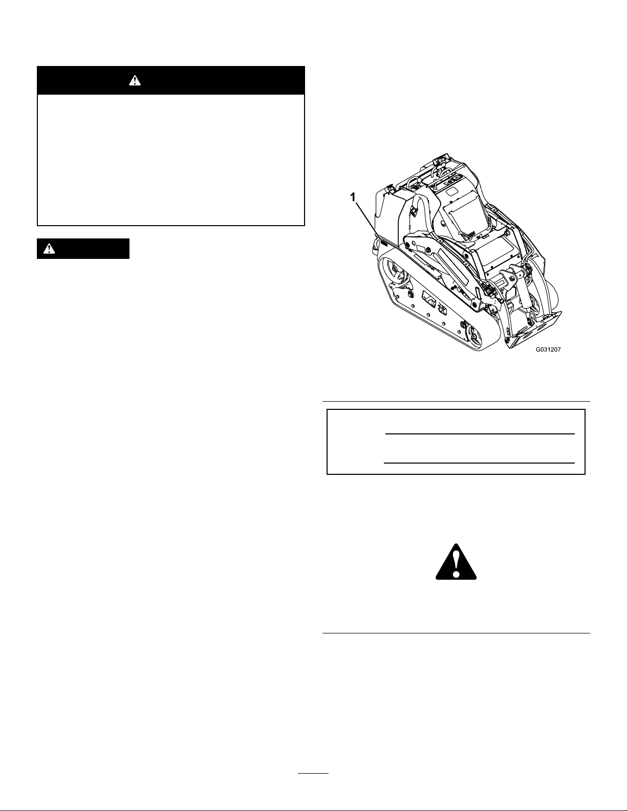
Wheneveryouneedservice,genuineT oroparts,oradditional
information,contactanAuthorizedServiceDealerorToro
CustomerServiceandhavethemodelandserialnumbersof
yourproductready.Figure1identiesthelocationofthe
modelandserialnumbersontheproduct.Writethenumbers
inthespaceprovided.
g031207
Figure1
1.Modelandserialnumberlocation
ItisaviolationofCaliforniaPublicResourceCode
Section4442or4443touseoroperatetheengineonany
forest-covered,brush-covered,orgrass-coveredlandunless
theengineisequippedwithasparkarrester,asdenedin
Section4442,maintainedineffectiveworkingorderorthe
engineisconstructed,equipped,andmaintainedforthe
preventionofre.
Theenclosedengineowner'smanualissuppliedfor
informationregardingtheUSEnvironmentalProtection
Agency(EP A)andtheCaliforniaEmissionControl
Regulationofemissionsystems,maintenance,and
warranty.Replacementsmaybeorderedthroughtheengine
manufacturer.
Introduction
Thismachineisacompacttoolcarrierintendedtomove
variousearthandmaterialsforlandscapingandconstruction
work.Itisdesignedtooperateawidevarietyofattachments
eachofwhichperformaspecializedfunction.
ModelNo.
SerialNo.
Thismanualidentiespotentialhazardsandhassafety
messagesidentiedbythesafety-alertsymbol(Figure2),
whichsignalsahazardthatmaycauseseriousinjuryordeath
ifyoudonotfollowtherecommendedprecautions.
g000502
Figure2
Safety-alertsymbol
Thismanualuses2wordstohighlightinformation.
Importantcallsattentiontospecialmechanicalinformation
andNoteemphasizesgeneralinformationworthyofspecial
attention.
Readthisinformationcarefullytolearnhowtooperateand
maintainyourproductproperlyandtoavoidinjuryand
productdamage.Youareresponsibleforoperatingthe
productproperlyandsafely.
©2017—TheToro®Company
8111LyndaleAvenueSouth
Bloomington,MN55420
Contactusatwww.Toro.com.
2
PrintedintheUSA
AllRightsReserved
Page 3

Contents
Safety...........................................................................4
SafeOperatingPractices...........................................4
StabilityData..........................................................7
SlopeIndicator.......................................................8
SafetyandInstructionalDecals.................................9
ProductOverview.........................................................13
Controls...............................................................13
MessageDisplay.................................................16
Specications........................................................17
Attachments/Accessories........................................17
Operation....................................................................18
ThinkSafetyFirst...................................................18
AddingFuel...........................................................18
PerformingDailyMaintenance.................................19
StartingtheEngine.................................................20
DrivingtheMachine...............................................20
ShuttingOfftheEngine..........................................20
MovingaNon-FunctioningMachine.........................20
UsingAttachments.................................................21
TransportingtheMachine........................................23
LiftingtheMachine................................................24
Maintenance.................................................................25
RecommendedMaintenanceSchedule(s)......................25
Pre-MaintenanceProcedures......................................26
UsingtheCylinderLocks.........................................26
AccessingInternalComponents...............................27
Lubrication...............................................................29
GreasingtheMachine.............................................29
EngineMaintenance..................................................30
ServicingtheAirCleaner.........................................30
ServicingtheEngineOil..........................................31
FuelSystemMaintenance...........................................33
DrainingtheFuelFilter/WaterSeparator...................33
ReplacingtheFuelFilterCanisterandIn-Line
Filter.................................................................33
CheckingtheFuelLinesandConnections..................33
BleedingtheFuelSystem.........................................34
DrainingtheFuelTanks..........................................34
ElectricalSystemMaintenance....................................34
ServicingtheBattery...............................................34
ServicingtheFuses.................................................38
DriveSystemMaintenance.........................................39
ServicingtheTracks................................................39
CoolingSystemMaintenance......................................42
ServicingtheCoolingSystem...................................42
BrakeMaintenance....................................................43
TestingtheParkingBrake........................................43
BeltMaintenance......................................................43
CheckingtheAlternator/FanBeltTension.................43
ControlsSystemMaintenance.....................................44
AdjustingtheControls............................................44
HydraulicSystemMaintenance....................................44
HydraulicFluidSpecications..................................44
CheckingtheHydraulic-FluidLevel..........................45
ReplacingtheHydraulicFilter..................................46
ChangingtheHydraulicFluid...................................46
CheckingtheHydraulicLines...................................47
Cleaning...................................................................48
RemovingDebris...................................................48
CleaningtheChassis...............................................48
Storage........................................................................49
Troubleshooting...........................................................50
Schematics...................................................................54
3
Page 4

Safety
Improperuseormaintenancebytheoperatororowner
canresultininjury.T oreducethepotentialforinjury,
complywiththesesafetyinstructionsandalways
payattentiontothesafety-alertsymbol
means:
instruction.Failuretocomplywiththeinstructionmay
resultinpersonalinjuryordeath.
Caution
,
W ar ning
,or
Danger
SafeOperatingPractices
Thisproductiscapableofamputatinghandsandfeet.Always
followallsafetyinstructionstoavoidseriousinjuryordeath.
WARNING
Engineexhaustcontainscarbonmonoxide,an
odorlessgasthatisfatalifinhaled.
Donotruntheengineindoorsorinanenclosed
area.
Training
•ReadtheOperator'sManualandothertrainingmaterial.If
theoperator(s)ormechanic(s)cannotreadEnglish,itis
theowner'sresponsibilitytoexplainthismaterialtothem.
•Becomefamiliarwiththesafeoperationoftheequipment,
operatorcontrols,andsafetysigns.
•Alloperatorsandmechanicsshouldbetrained.The
ownerisresponsiblefortrainingtheusers.
•Neverletchildrenoruntrainedpeopleoperateorservice
theequipment.Localregulationsmayrestricttheageof
theoperator.
•Theowner/usercanpreventandisresponsiblefor
accidentsorinjuriesoccurringtohimselforherself,other
peopleorproperty.
Preparation
DANGER
Theremaybeburiedpower,gas,and/ortelephone
linesintheworkarea.Diggingintothemmay
causeashockoranexplosion.
Havethepropertyorworkareamarkedforburied
linesanddonotdiginmarkedareas.Contactyour
localmarkingserviceorutilitycompanytohavethe
propertymarked(forexample,intheUS,call811or
inAustralia,call1100forthenationwidemarking
service).
•Evaluatetheterraintodeterminewhataccessoriesand
attachmentsyouneedtoproperlyandsafelyperformthe
job.Useonlytheaccessoriesandattachmentsthatare
approvedbythemanufacturer.
,which
—personalsafety
•Wearappropriateclothingincludinggloves,eye
protection,longpants,substantialslip-resistantfootwear,
andhearingprotection.Tiebacklonghairanddonot
wearjewelry.
•Inspecttheareawhereyouwillusetheequipmentand
removeallobjects,suchasrocks,toys,andwire,thatthe
machinecouldthrow.
•Useextracarewhenhandlingfuel.Fuelisammableand
itsvaporsareexplosive.
–Useonlyanapprovedcontainer.
–Neverremovethefuelcaporaddfuelwiththeengine
running.Allowtheenginetocoolbeforerefueling.
Donotsmoke.
–Neverrefuelordrainthemachineindoors.
•Checkthattheoperator'spresencecontrols,safety
switches,andshieldsareattachedandfunctioning
properly.Donotoperatethemachineunlesstheyare
functioningproperly.
Operation
•Neverrunanengineinanenclosedarea.
•Operatethemachineonlyingoodlight,keepingaway
fromholesandhiddenhazards.
•Ensurethatallthedrivesareinneutralandtheparking
brakeisengagedbeforestartingtheengine.Startthe
engineonlyfromtheoperator'sposition.
•Slowdownanduseextracareonhillsides.Ensureto
travelintherecommendeddirectiononhillsides.Turf
conditionscanaffectthestabilityofthemachine.
•Slowdownandusecautionwhenmakingturns,crossing
roadsandsidewalks,andwhenchangingdirectionson
slopes.
•Neveroperatethemachinewithouttheguardssecurelyin
place.Ensurethatalltheinterlocksareattached,adjusted,
andfunctioningproperly.
•Donotchangetheenginegovernorsettingoroverspeed
theengine.
•Parkthemachineonalevelsurface,lowertheimplements,
disengagetheauxiliaryhydraulics,engagetheparking
brake,shutofftheengine,andremovethekeybefore
leavingtheoperator'spositionforanyreason.
•Keepyourhandsandfeetawayfromthemoving
attachments.
•Lookbehindanddownbeforebackinguptoensurethat
thepathisclear.
•Nevercarrypassengersandkeeppetsandbystanders
away.
•Slowdownandusecautionwhenmakingturnsand
crossingroadsandsidewalks.
•Donotoperatethemachinewhenyouaretired,ill,or
undertheinuenceofalcoholordrugs.
4
Page 5

•Usecarewhenloadingorunloadingthemachineintoa
trailerortruck.
•Usecarewhenapproachingblindcorners,shrubs,trees,
orotherobjectsthatmayobscurevision.
•Readalltheattachmentmanuals.
•Ensurethattheareaisclearofpeoplebeforeoperating
themachine.Stopthemachineifanyoneentersthearea.
•Neverleavearunningmachineunattended.Alwayslower
theloaderarms,shutofftheengine,engagetheparking
brake,andremovethekeybeforeleaving.
•Donotexceedtheratedoperatingcapacity ,asthe
machinemaybecomeunstable,whichmayresultinloss
ofcontrol.
•Donotcarryaloadwiththearmsraised.Alwayscarry
loadsclosetotheground.
•Donotoverloadtheattachmentandalwayskeeptheload
levelwhenraisingtheloaderarms.Logs,boards,and
otheritemscouldrolldowntheloaderarms,injuringyou.
•Neverjerkthecontrols;useasteadymotion.
•Watchfortrafcwhenoperatingnearorcrossing
roadways.
•Donottouchpartsthatmaybehotfromoperation.
Allowthemtocoolbeforeattemptingtomaintain,adjust,
orservicethemachine.
•Checkforoverheadclearances(i.e.,branches,doorways,
andelectricalwires)beforedrivingunderanyobjectsand
donotcontactthem.
•Operatethemachineinareaswheretherearenoobstacles
incloseproximitytoyou.Failuretomaintainadequate
distancefromtrees,walls,andotherbarriersmayresult
ininjuryasthemachinebacksupduringoperationif
youarenotattentivetothesurroundings.Operatethe
machineonlyinareaswherethereissufcientclearance
foryoutosafelymaneuver.
•Notethelocationofunmarkedobjectsandstructures,
suchasundergroundstoragetanks,wells,andseptic
systems.
•Locatethepinchpointareasmarkedonthemachineand
attachmentsandkeepyourhandsandfeetawayfrom
theseareas.
•Beforeoperatingthemachinewithanattachment,ensure
thattheattachmentisproperlyinstalledandthatitisa
genuineToroattachment.
SlopeOperation
Slopesareamajorfactorrelatedtoloss-of-controland
tip-overaccidents,whichcanresultinsevereinjuryordeath.
Allslopesrequireextracaution.
•Donotoperatethemachineonhillsidesorslopes
exceedingtheanglesrecommendedonStabilityData
(page7),andthoseintheattachmentOperator'sManual.
SeealsotheSlopeIndicator(page8).
•Operatethemachineupanddownslopeswiththe
heavyendofthemachineuphill.Weightdistribution
changes.Anemptybucketmakestherearofthemachine
theheavyend,andafullbucketmakesthefrontofthe
machinetheheavyend.Mostotherattachmentsmakethe
frontofmachinetheheavyend.
•Raisingtheloaderarmsonaslopeaffectsthestabilityof
themachine.Wheneverpossible,keeptheloaderarmsin
theloweredpositionwhenonslopes.
•Donotremoveoraddattachmentsonaslope.
•Removeobstaclessuchasrocks,treelimbs,etc.fromthe
workarea.Watchforholes,ruts,orbumps,asuneven
terraincouldoverturnthemachine.Tallgrasscanhide
obstacles.
•UseonlyToro-approvedattachments.Attachmentscan
changethestabilityandtheoperatingcharacteristicsof
themachine.Youmayvoidthewarrantyifyouusethe
machinewithunapprovedattachments.
•Keepallmovementsonslopesslowandgradual.Donot
makesuddenchangesinspeedordirection.
•Avoidstartingorstoppingonaslope.Ifthemachine
losestraction,proceedslowly,straightdowntheslope.
•Avoidturningonslopes.Ifyoumustturn,turnslowly
andkeeptheheavyendofthemachineuphill.
•Donotoperateneardrop-offs,ditches,orembankments.
Themachinecouldsuddenlyturnoverifatrackgoes
overtheedgeofaclifforditch,orifanedgecavesin.
•Usecautionwhenoperatingonwetgrass.Reduced
tractioncouldcausesliding.
•Donotparkthemachineonahillsideorslopewithout
loweringtheattachmenttotheground,engagingthe
parkingbrake(ifequipped),andchockingthetracks.
•Onmachineswithanoperatorplatform,donottryto
stabilizethemachinebyputtingyourfootontheground.
•Donotplaceyourfeetundertheplatform,ifequipped
onyourmachine.
•Lightningcancausesevereinjuryordeath.Iflightning
isseenorthunderisheardinthearea,donotoperate
themachine;seekshelter.
5
Page 6

MaintenanceandStorage
•Parkthemachineonalevelsurface,disengagethe
auxiliaryhydraulics,lowertheattachment,engagethe
parkingbrake(ifequippedonyourmachine),shutoff
theengine,andremovethekey .Waitforallmovement
tostopandallowthemachinetocoolbeforeadjusting,
cleaning,storing,orrepairingit.
•Cleandebrisfromtheattachments,drives,mufers,and
enginetohelppreventres.Wipeupanyspilledoilor
fuel.
•Allowtheenginetocoolbeforestoringanddonotstore
nearames.
•Neverallowuntrainedpersonneltoservicethemachine.
•Usejackstandstosupportthecomponentswhen
required.
•Carefullyreleasepressurefromcomponentswithstored
energy.
•Keepyourhandsandfeetawayfromthemovingparts.
Ifpossible,donotmakeadjustmentswiththeengine
running.
•Disconnectthebatterybeforemakinganyrepairs;refer
toUsingtheBattery-DisconnectSwitch(page35).
•Chargethebatteryinanopen,well-ventilatedarea,
awayfromsparkandames.Unplugthechargerbefore
connectingordisconnectingitfromthebattery.Wear
protectiveclothinganduseinsulatedtools.
•Batteryacidispoisonousandcancauseburns.Avoid
contactwithskin,eyes,andclothing.Protectyourface,
eyes,andclothingwhenworkingwithabattery.
•Batterygasescanexplode.Keepcigarettes,sparks,and
amesawayfromthebattery.
•Keepallpartsingoodworkingconditionandallhardware
tightened.Replaceallwornordamageddecals.
•Ifanymaintenanceorrepairrequirestheloaderarmsto
beintheraisedposition,securethearmsintheraised
positionwiththehydraulic-cylinderlock(s).
•Securetheloader-armvalvewiththeloader-valvelock(if
equippedonyourmachine)anytimeyouneedtostopthe
machinewiththeloaderarmsraised.
•Keepallnutsandboltstight.Keeptheequipmentin
goodcondition.
•Nevertamperwiththesafetydevices.
•Keepthemachinefreeofgrass,leaves,orotherdebris
buildup.Wipeupanyspilledoilorfuel.Allowthe
machinetocoolbeforestoring.
•Useextracarewhenhandlingfuel;itisammableandits
vaporsareexplosive.
–Useonlyanapprovedcontainer.
–Neverremovethefuelcap(s)oraddfuelwhenthe
engineisrunning.Allowtheenginetocoolbefore
refueling.Donotsmoke.
–Neverrefuelthemachineindoors.
–Neverstorethemachineorfuelcontainerinside
wherethereisanopename,suchasnearawater
heaterorfurnace.
–Neverllacontainerwhileitisinsideavehicle,trunk,
pick-upbed,oranysurfaceotherthantheground.
–Keepthecontainernozzleincontactwiththetank
duringlling.
–Donotstorefuelnearamesordrainindoors.
•Stopandinspecttheequipmentifyoustrikeanobject.
Makeanynecessaryrepairsbeforestarting.
•UseonlygenuineTororeplacementparts.
•Keepyourbodyandhandsawayfrompinholeleaks
ornozzlesthatejecthigh-pressurehydraulicuid.Use
cardboardorpapertondhydraulicleaks;neveruse
yourhands.Hydraulicuidescapingunderpressurecan
penetrateskinandcauseinjuryrequiringsurgerywithin
afewhoursbyaqualiedsurgeon;otherwise,gangrene
mayresult.
6
Page 7
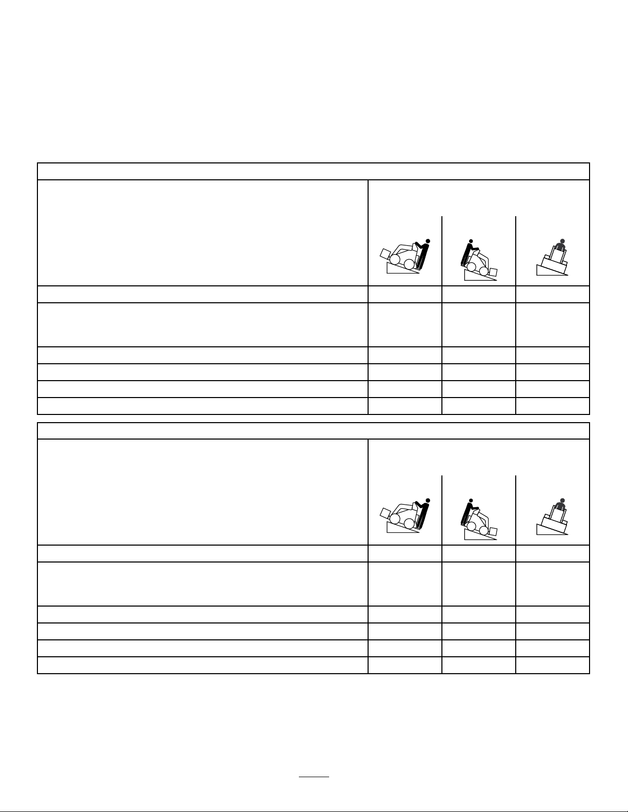
StabilityData
Thefollowingtableslistthemaximumsloperecommendedforthetractionunitinthepositionslistedinthetables.Slopesover
thelisteddegreemaycausethetractionunittobecomeunstable.Thedatainthetablesassumethattheloaderarmsarefully
lowered;raisedarmsmayaffectthestability.
Ineachattachmentmanualisasetof3stabilityratings,1foreachhillposition.Todeterminethemaximumslopeyoucan
traversewiththeattachmentinstalled,ndthedegreeofslopethatcorrespondstothestabilityratingsoftheattachment.
Example:IftheattachmentinstalledonaTXModel22327tractionunithasafrontuphillratingofB,aRearUphillratingof
D,andaSideUphillratingofC,thenyoucoulddriveforwardupa19°slope,rearwardupa11°slope,orsidewaysona11°
slope,aslistedinthefollowingtable.
Models22327,22327G,and22327HD
MaximumRecommendedSlopewhen
Operatingwith:
FrontUphillRearUphill
Conguration
Tractionunitwithoutattachment
Tractionunitwithanattachmentratedwith1ofthefollowingstabilityratingsfor
eachslopeposition:*
A
B
C16°17°11°
D
E
Model22328and22328HD
15°19°16°
25°25°20°
19°20°15°
14°11°8°
5°5°5°
MaximumRecommendedSlopewhen
Operatingwith:
FrontUphillRearUphill
SideUphill
SideUphill
Conguration
Tractionunitwithoutattachment
Tractionunitwithanattachmentratedwith1ofthefollowingstabilityratingsfor
eachslopeposition:*
A
B
C18°15°14°
D
E
16°19°19°
25°25°23°
21°19°18°
15°10°10°
5°5°5°
7
Page 8
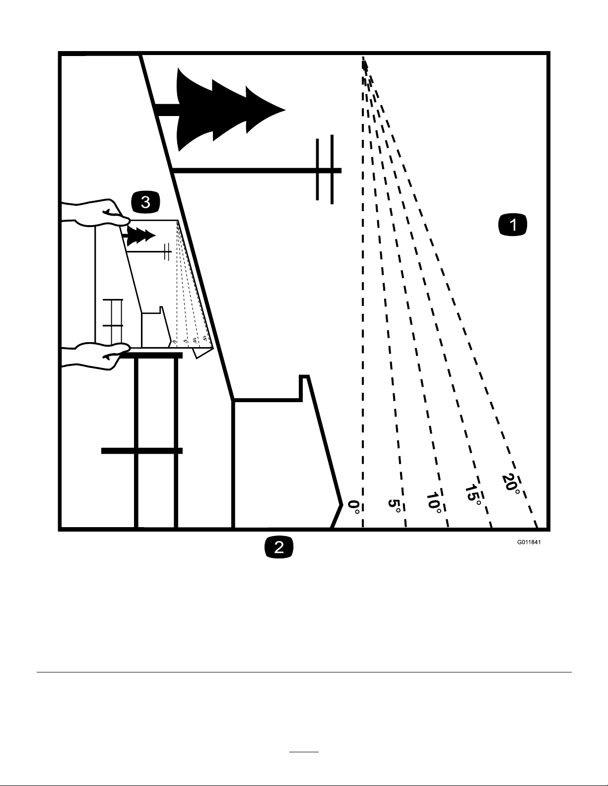
SlopeIndicator
G011841
Figure3
Thispagemaybecopiedforpersonaluse.
1.Todeterminethemaximumslopeyoucansafelyoperatethemachineon,refertotheStabilityDatasection.Usetheslope
indicatortodeterminethedegreeofslopeofhillsbeforeoperating.Donotoperatethismachineonaslopegreaterthanthat
speciedintheStabilityDatasection.Foldalongtheappropriatelinetomatchtherecommendedslope.
2.Alignthisedgewithaverticalsurface,atree,building,fencepole,etc.
3.Exampleofhowtocompareslopewithfoldededge
8
g011841
Page 9
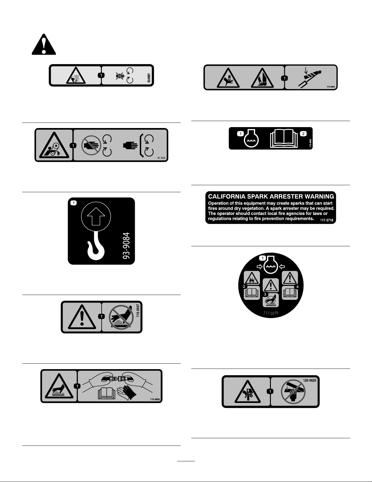
SafetyandInstructionalDecals
Safetydecalsandinstructionsareeasilyvisibletotheoperatorandarelocatednearanyareaofpotential
danger.Replaceanydecalthatisdamagedormissing.
93-6681
1.Cutting/dismembermenthazard,fan—stayawayfrom
movingparts.
93-7814
1.Entanglementhazard,belt—stayawayfrommovingparts.
decal93-6681
decal115-4858
115-4858
1.Crushinghazardofhandsorfeet—installthecylinderlock.
decal115-4865
115-4865
decal93-7814
1.Enginecoolant
2.ReadtheOperator's
Manual.
decal117-2718
117-2718
93-9084
1.Liftpoint/Tie-downpoint
115-2047
1.Warning—donottouchthehotsurface.
115-4855
1.Hotsurface/burnhazard—wearprotectivegloveswhen
handlingthehydrauliccouplersandreadtheOperator's
Manualforinformationonhandlinghydrauliccomponents.
decal93-9084
decal117-3276
117-3276
decal115-2047
decal115-4855
1.Enginecoolantunder
pressure
2.Explosionhazard—read
theOperator'sManual.
3.Warning—donottouchthe
hotsurface.
4.Warning—readthe
Operator'sManual.
decal120-0625
120-0625
1.Pinchpoint,hand—keephandsaway.
9
Page 10
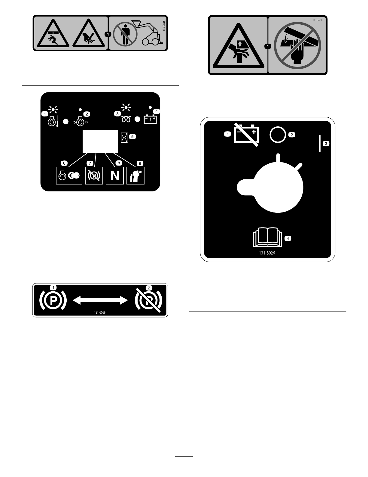
130-2836
1.Crushinghazard;cuttinghazard—keepawayfromthe
bucketandtheliftarm.
130-7637
decal130-2836
decal131-0711
131-0711
1.Crushinghazard—keepawayfrompinchpointsand
actuatingparts.
decal130-7637
1.Blinking
6.Enginestart
light—engine-coolant
temperature
2.Steadylight—engine-oil
7.Parkingbrakedisengaged
pressure
3.Blinkinglight—glowplug8.Tractionneutral
4.Steadylight—battery
9.Auxiliaryleverneutral
warning
5.Hourmeter
131-0709
1.Parkingbrake—engage2.Parkingbrake—disengage
decal131-8026
131-8026
1.Battery
power—disconnect
2.On4.ReadtheOperator's
decal131-0709
3.Off
Manual.
10
Page 11
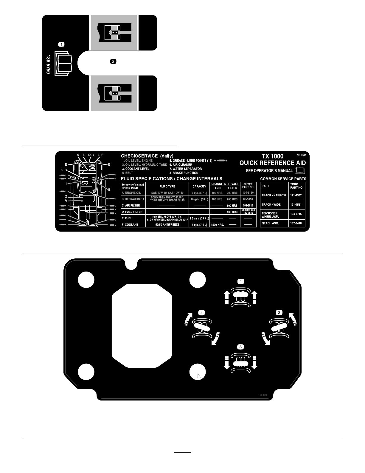
decal136-5750
136-5750
1.ReadtheOperator's
Manual.
2.Tensionblockguide
decal131-0597
131-0597
1.Moveforward
2.Turnright
decal131-0708
131-0708
3.Moverearward
4.Turnleft
11
Page 12
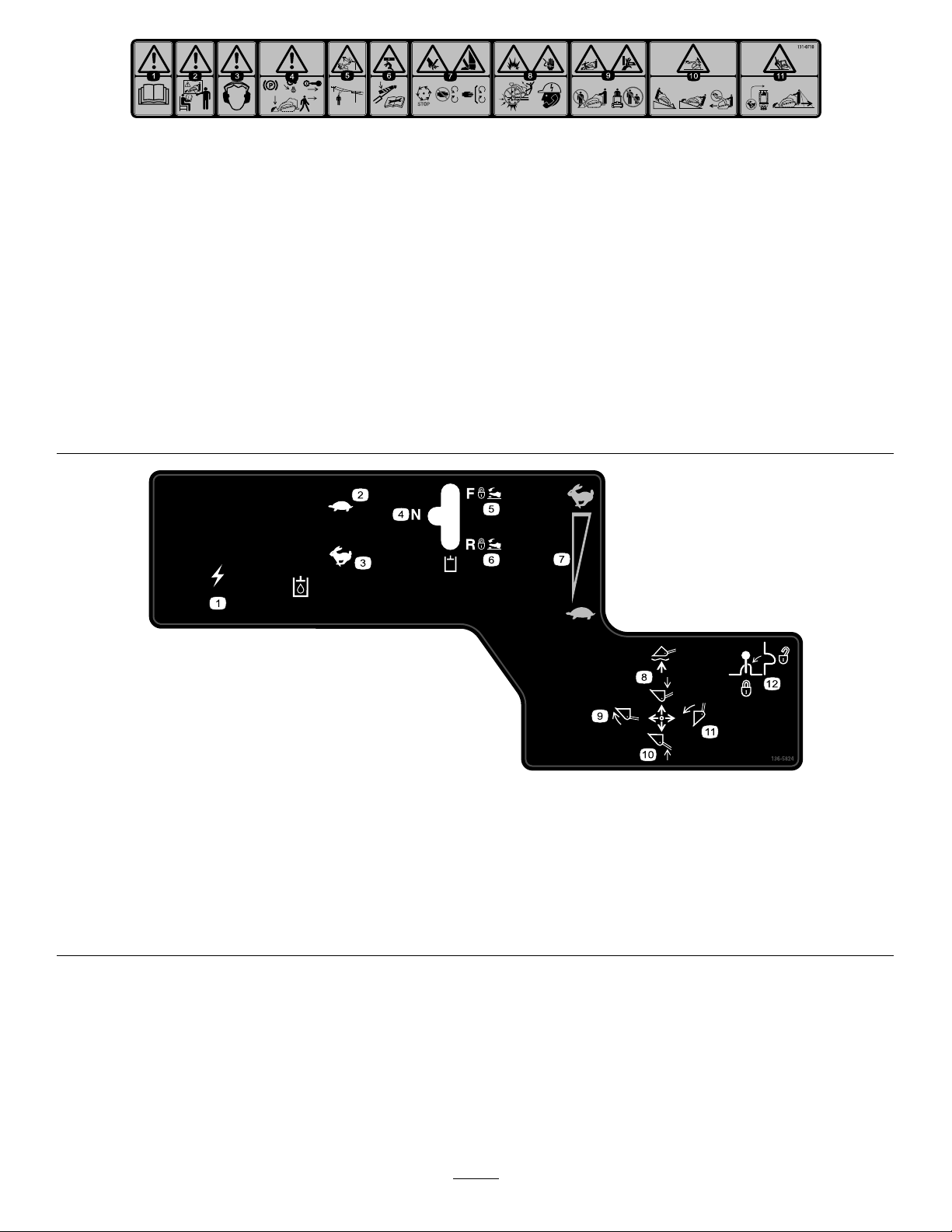
decal131-0710
131-0710
1.Warning—readtheOperator'sManual.7.Cutting/severinghazardofhandorfoot—waitforallmoving
partstostopbeforeservicing;keepawayfrommovingparts;
keepallguardsandshieldsinplace.
2.Warning—receivetrainingbeforeoperatingthemachine.
8.Explosionhazard;electrocutionhazard—callthelocalutilities
hotlinebeforebeginningworkinanarea.
3.Warning—wearhearingprotection.
9.Crushinghazard—keepawayfromthebucketwhenoperating
themachine;keepbystandersawayfromthemachine.
4.Warning—engagetheparkingbrake,lowerthebuckettothe
ground,shutofftheengine,andremovethekeyfromthe
ignitionbeforeleavingthemachine.
10.Tippinghazard—alwaysmoveupordownslopeswiththe
bucketlowered;neverdriveonaslopewiththebucketraised;
alwaysoperatewiththeheavyenduphill;alwayscarryloads
low;neverjerkthecontrollevers;useasteady,evenmotion.
5.Electrocutionhazard,powerlines—checkforpowerlinesin
theareabeforeusingthemachine.
11.Tippinghazard—donotmakefastturns;alwayscheckbehind
youbeforereversingthemachine.
6.Crushinghazard—keepawayfrompinchpoints;read
theOperator'sManualbeforeservicingorperforming
maintenance.
136-5824
1.Powersocket7.Enginespeed
2.Hydraulicuid—slow8.Lower/oattheattachment.
3.Hydraulicuid—fast9.Tilttheattachmentforward.
4.Hydraulicattachment—neutral10.Raisetheattachment.
5.Hydraulicattachment—forward
11.Tilttheattachmentrearward.
6.Hydraulicattachment—reverse12.Leverlock
12
decal136-5824
Page 13
ProductOverview
Controls
Becomefamiliarwithallthecontrols(Figure5)beforeyou
starttheengineandoperatethetractionunit.
ControlPanel
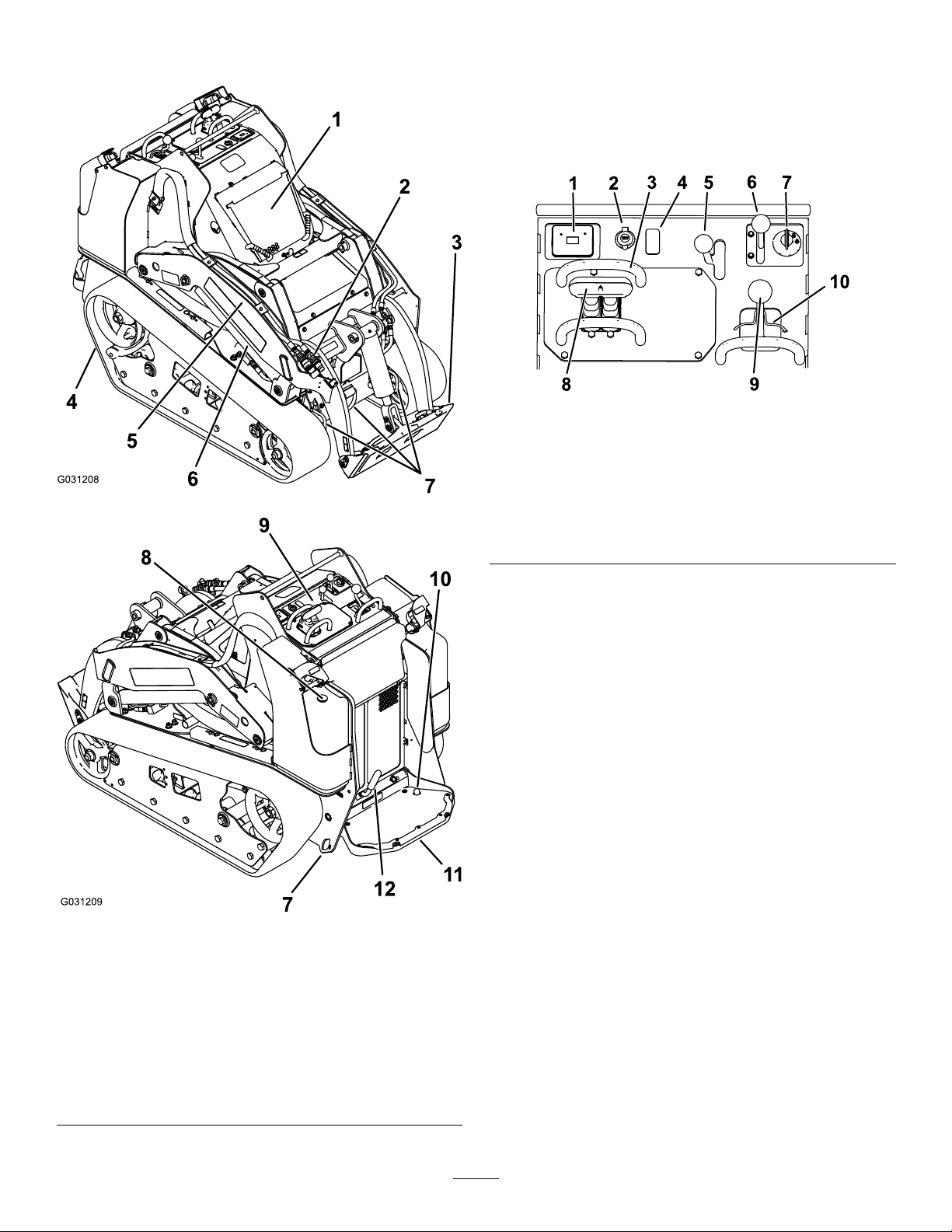
g205233
Figure5
1.Messagedisplay6.Throttlelever
2.Powersocket7.Keyswitch
g031208
3.Referencebar
4.Plug
5.Auxiliaryhydraulicslever10.Loaderlock
8.Tractioncontrol
9.Loader-arm/attachment-tilt
lever
Figure4
1.Hood
2.Auxiliaryhydraulic
couplers
3.Mountplate
4.Track10.Auxiliaryhydraulicslock
5.Loaderarm
6.Liftcylinder
7.Tie-down/liftloop
8.Fuelgauge
9.Controlpanel
switch
11.Operatorplatform
12.Parkingbrake
KeySwitch
Thekeyswitch,usedtostartandshutofftheengine,has
3positions:OFF,RUN,andSTART.RefertoStartingthe
Engine(page20).
ThrottleLever
Movethecontrolforwardtoincreasetheenginespeedand
rearwardtodecreasespeed.
ReferenceBar
Whendrivingthetractionunit,usethereferencebaras
ahandleandaleveragepointforcontrollingthetraction
g031209
controlandtheauxiliary-hydraulicslever.Toensuresmooth,
controlledoperation,donottakebothhandsoffthereference
barwhileoperatingthemachine.
13
Page 14
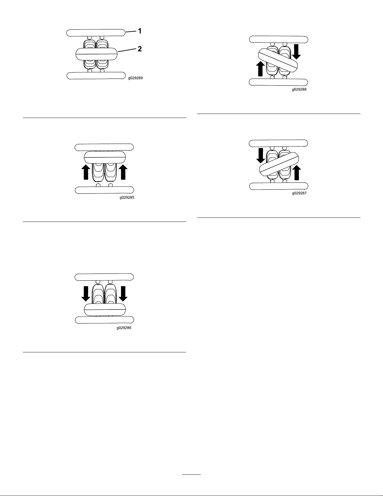
TractionControl
1.Referencebar
2.Tractioncontrol
Figure6
•Toturnright,rotatethetractioncontrolclockwise(Figure
9).
g029289
g029288
Figure9
•Tomoveforward,movethetractioncontrolforward
(Figure7).
Figure7
•Tomoverearward,movethetractioncontrolrearward
(Figure8).
Important:Whenreversing,lookbehindyoufor
obstructionsandkeepyourhandsonthereference
bar.
•Toturnleft,rotatethetractioncontrolcounterclockwise
(Figure10).
g029285
Figure10
g029287
•Tostopthemachine,releasethetractioncontrol(Figure
6).
Note:Thefartheryoumovethetractioncontrolinany
direction,thefasterthemachinemovesinthatdirection.
Figure8
g029286
14
Page 15
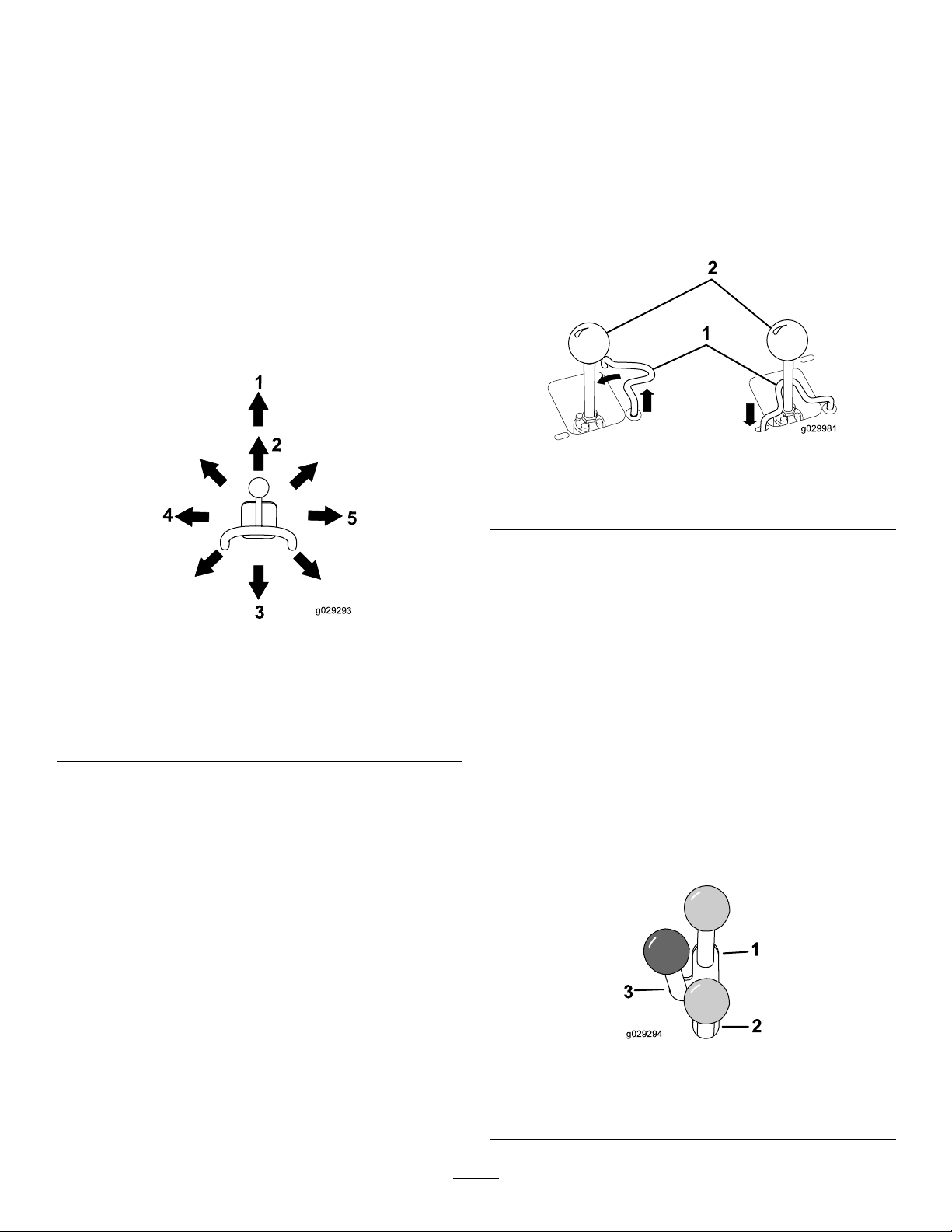
LoaderArm/Attachment-TiltLever
Loader-ValveLock
•Totilttheattachmentforward,slowlymovetheleverto
theright(Figure11).
•Totilttheattachmentrearward,slowlymovethelever
totheleft(Figure11).
•Tolowertheloaderarms,slowlymovetheleverforward
(Figure11).
•Toraisetheloaderarms,slowlymovetheleverrearward
(Figure11).
•Tolowertheloaderarmstoadetent(oat)position,push
theleverfullyforward(Figure11).
Note:Thisallowsattachmentssuchasthelevelerand
thehydraulicbladetofollowthecontoursoftheground
(i.e.,oat)whengrading.
Theloader-valvelocksecurestheloaderarm/attachment-tilt
leversothatyoucannotpushitforward.Thishelpsto
ensurethatnooneaccidentallylowerstheloaderarmsduring
maintenance.Securetheloaderarmswiththelockanytime
youneedtoshutoffthemachinewiththeloaderarmsraised.
Tosetthelock,liftuponitsothatitclearstheholein
thecontrolpanelandswingittotheleft,infrontofthe
loader-armlever,pushingitdownintothelockedposition
(Figure12).
Figure12
1.Loaderarm/attachment-tilt
lever
2.Loader-valvelock
g029981
Figure11
1.Detent(oat)position
2.Lowertheloaderarms.5.Tilttheattachment
3.Raisetheloaderarms.
4.Tilttheattachment
rearward.
forward.
Bymovingthelevertoanintermediateposition(e.g.,
forwardandleft),youcanmovetheloaderarmsandtiltthe
attachmentatthesametime.
Loader-Control-ReferenceBar
Theloader-control-referencebarhelpsstabilizeyourhand
g029293
whileoperatingtheloaderarm/attachment-tiltlever(Figure
4).
Auxiliary-HydraulicsLever
•Tooperateahydraulicattachmentintheforward
direction,movetheauxiliary-hydraulicsleverforward
(Figure13).
•Tooperateahydraulicattachmentinthereversedirection,
movetheauxiliary-hydraulicsleverrearward(Figure13).
Note:IfyoureleasetheleverwhileintheFORWARDor
REVERSEposition,theleverautomaticallyreturnstothe
NEUTRALposition(Figure13).
15
1.Forward-owhydraulics
2.Reverse-owhydraulics
g029294
Figure13
3.Neutral
Page 16
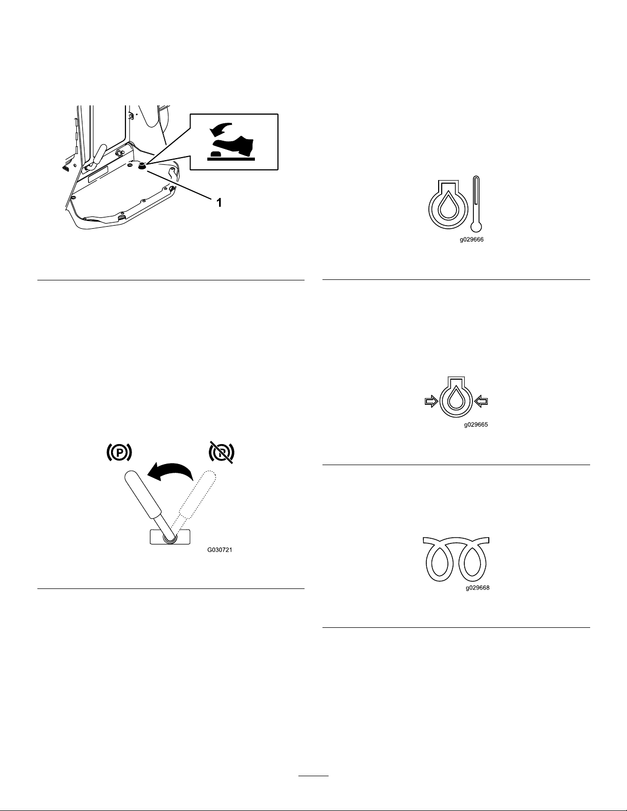
Auxiliary-Hydraulics-LockSwitch
MessageDisplay
Useyourrightfoottopresstheauxiliary-hydraulics-lock
switchtolocktheauxiliary-hydraulicsleverintheFORW ARD
orREARWARDpositionandfreeyourhandforothercontrols
(Figure5).
Figure14
1.Auxiliary-hydraulics-lock
Parking-BrakeLever
•Toengagetheparkingbrake,rotatethelevertoleft
(Figure15).
Note:Thetractionunitmayrollslightlybeforethe
brakesengageinthedrivesprocket.
Engine-Coolant-TemperatureLight
Iftheenginecoolantbecomestoohot,thelightontheleft
ashesandthehornsounds(Figure16).Ifthishappens,
disengagetheauxiliaryhydraulicsandletthemachinerunat
highidletoallowthecoolingsystemtocoolthemachine.
Checkthecoolantlevelwhentheenginehasfullycooled.
Important:Donotshutofftheengine,asthismay
causethemachinetooverheat.
g205234
g029666
Figure16
Engine-Oil-PressureLight
Iftheengine-oil-pressurebecomestoolow,thelightonthe
leftilluminatessteadily(Figure17).Ifthishappens,shutoff
theengineimmediatelyandchecktheoillevel.Ifitislow,add
oilandlookforpossibleleaks.
•Toreleasethebrake,rotatethebrakelevertotheright.
Note:Youmayneedtoadjustthetractioncontrolto
releasethebrakepinsandrotatethelever.
Figure15
FuelGauge
Thisgaugemeasurestheamountoffuelinthefueltank(s).
g029665
Figure17
Glow-PlugLight
Thelightontherightasheswhiletheglowplugsarecharged
andwarmingtheengine(Figure18).
g030721
g029668
Figure18
16
Page 17
Battery-ChargeLight
Ifthebatterychargebecomestoolow,thelightontheright
illuminatessteadily(Figure19).Ifthishappens,shutoffthe
engineandchargeorreplacethebattery.RefertoServicing
theBattery(page34).
Figure19
HourMeter
Thehourmeterdisplaysthenumberofhoursofoperation
thathavebeenloggedonthetractionunitandthefollowing
indicators:
•Enginestart—displayswhenyoustarttheengine
Figure20
•Parkingbrake—displayswhenyoudisengagetheparking
brake
Specications
Note:Specicationsanddesignaresubjecttochange
withoutnotice.
Model22327
Width
Length
Height
Weight
Operatingcapacity(withstandard
g029667
g029974
bucket)
Tippingcapacity(withstandardbucket)1296kg(2,857lb)
Wheelbase
Dumpheight(withstandardbucket)155cm(61inches)
Reach—fullyraised(withstandard
bucket)
Heighttohingepin(withstandard
bucketinhighestposition)
Model22328
Width
Length
Height
Weight
Operatingcapacity(withstandard
bucket)
Tippingcapacity(withstandardbucket)1296kg(2,857lb)
Wheelbase
Dumpheight(withstandardbucket)155cm(61inches)
Reach—fullyraised(withstandard
bucket)
Heighttohingepin(withstandard
bucketinhighestposition)
85cm(33inches)
256cm(101inches)
138cm(54inches)
1234kg(2,720lb)
454kg(1,000lb)
104cm(41inches)
62cm(25inches)
206cm(81inches)
103cm(41inches)
256cm(101inches)
138cm(54inches)
1297kg(2,860lb)
454kg(1,000lb)
104cm(41inches)
62cm(25inches)
206cm(81inches)
Figure21
•Tractionneutral—displayswhenthetractioncontrolis
intheNEUTRALposition
Figure22
•Auxiliaryleverneutral—displayswhentheauxiliarylever
isintheNEUTRALposition
Figure23
g030520
Attachments/Accessories
AselectionofToroapprovedattachmentsandaccessoriesis
availableforusewiththemachinetoenhanceandexpand
itscapabilities.ContactyourAuthorizedServiceDealeror
Distributororgotowww .Toro.comforalistofallapproved
attachmentsandaccessories.
Important:UseonlyToroapprovedattachments.
g029211
g029975
Otherattachmentsmaycreateanunsafeoperating
environmentordamagethetractionunit.
Tobestprotectyourinvestmentandmaintainoptimal
performanceofyourToroequipment,countonTorogenuine
parts.Whenitcomestoreliability,T orodeliversreplacement
partsdesignedtotheexactengineeringspecicationofour
equipment.Forpeaceofmind,insistonTorogenuineparts.
17
Page 18
Operation
G009027
1
2
AddingFuel
Note:Determinetheleftandrightsidesofthemachine
fromthenormaloperatingposition.
Important:Beforeoperating,checktheuidlevelsand
removedebrisfromthetractionunit.Also,ensurethat
theareaisclearofpeopleanddebris.Y oushouldalso
knowandhavemarkedthelocationsofalltheutility
lines.
ThinkSafetyFirst
Carefullyreadallsafetyinstructionsandsymbolsinthe
safetysection.Knowingthisinformationcouldhelpyouor
bystandersavoidinjury.
CAUTION
Thismachineproducessoundlevelsthatcancause
hearinglossthroughextendedperiodsofexposure.
Wearhearingprotectionwhenoperatingthis
machine.
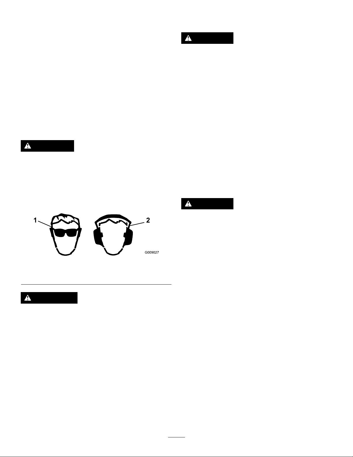
Useprotectiveequipmentforyoureyes,ears,hands,feet,
andhead.
DANGER
Incertainconditions,fuelisextremelyammable
andhighlyexplosive.Areorexplosionfromfuel
canburnyouandothersandcandamageproperty.
•Fillthefueltanksoutdoors,inanopenarea,
whentheengineiscold.Wipeupanyfuelthat
spills.
•Neverllthefueltanksinsideanenclosed
trailer.
•Neversmokewhenhandlingfuelandstayaway
fromanopenameorwherefuelfumesmaybe
ignitedbyaspark.
•Storefuelinanapprovedcontainerandkeepit
outofthereachofchildren.Neverbuymore
thana30-daysupplyoffuel.
•Donotoperatewithoutentireexhaustsystemin
placeandinproperworkingcondition.
DANGER
Incertainconditionsduringfueling,static
electricitycanbereleased,causingasparkthatcan
ignitethefuelvapors.Areorexplosionfromfuel
canburnyouandothersandcandamageproperty.
Figure24
1.Weareyeprotection.2.Wearhearingprotection.
WARNING
Youcouldfallofftheplatformandbeseriously
injuredduringoperation.
Donotmovethemachineunlessyouarestanding
withbothfeetontheplatformandyourhandsare
holdingontothehandles.
•Alwaysplacefuelcontainersonthegroundaway
g009027
fromyourvehiclebeforelling.
•Donotllfuelcontainersinsideavehicleoron
atruckortrailerbed,becauseinteriorcarpets
orplastictruckbedlinersmayinsulatethe
containerandslowthelossofanystaticcharge.
•Whenpractical,removeequipmentfromthe
truckortrailerandrefueltheequipmentwithits
wheelsontheground.
•Ifthisisnotpossible,thenrefuelsuchequipment
onatruckortrailerfromaportablecontainer
ratherthanfromafuel-dispensernozzle.
•Ifyoumustuseafuel-dispensernozzle,keepthe
nozzleincontactwiththerimofthefueltank
orcontaineropeningatalltimesuntilfuelingis
complete.
18
Page 19

WARNING
Fuelisharmfulorfatalifswallowed.Long-term
exposuretovaporscancauseseriousinjuryand
illness.
•Avoidprolongedbreathingofvapors.
•Keepyourfaceawayfromthenozzleandfuel
tankopening.
•Keepfuelawayfromyoureyesandskin.
FuelRecommendations
Useonlyclean,freshdieselfuelorbiodieselfuelswithlow
(<500ppm)orultralow(<15ppm)sulfurcontent.The
minimumcetaneratingshouldbe40.Purchasefuelin
quantitiesthatyoucanusewithin180daystoensurefuel
freshness.
Usesummer-gradedieselfuel(No.2-D)attemperatures
above-7°C(20°F)andwintergrade(No.1-DorNo.
1-D/2-Dblend)belowthattemperature.Usingwinter-grade
fuelatlowertemperaturesprovideslowerashpointand
coldowcharacteristics,whicheasesstartingandreduces
fuellterplugging.
FillingtheFuelTanks
Fueltankcapacity:41L(11USgallons)
FillthefueltanksasshowninFigure25.
Note:Thefuel-tankcapsclickwhenyouclosethemsecurely.
Usethebracketstolockthefueltanks.
Usingsummer-gradefuelabove-7°C(20°F)contributes
towardlongerfuelpumplifeandincreasedpowercompared
towinter-gradefuel.
Important:Donotusekeroseneorgasolineinsteadof
dieselfuel.Failuretoobservethiscautionwilldamage
theengine.
BiodieselReady
Thismachinecanalsouseabiodieselblendedfuelofup
toB20(20%biodiesel,80%petrodiesel).Thepetrodiesel
portionshouldbeloworultralowsulfur.Observethe
followingprecautions:
•Thebiodieselportionofthefuelmustmeetspecication
ASTMD6751orEN14214.
•TheblendedfuelcompositionshouldmeetASTMD975
orEN590.
•Paintedsurfacesmaybedamagedbybiodieselblends.
•UseB5(biodieselcontentof5%)orlesserblendsincold
weather.
•Monitorseals,hoses,gasketsincontactwithfuelasthey
maydegradeovertime.
•Fuellterpluggingmayoccurforatimeafterconverting
tobiodieselblends.
g029669
Figure25
PerformingDaily Maintenance
Beforestartingthemachineeachday,performtheEach
Use/DailyprocedureslistedintheMaintenance(page25).
Important:Checkthehydraulic-uidlevelandbleed
thefuelsystembeforestartingtheenginefortherst
time;refertoCheckingtheHydraulic-FluidLevel(page
45)andBleedingtheFuelSystem(page34).
•Contactyourdistributorformoreinformationon
biodiesel.
19
Page 20

StartingtheEngine
ShuttingOfftheEngine
1.Ensurethattheauxiliary-hydraulicsleverand
traction-controlareintheNEUTRALposition.
2.MovethethrottlelevermidwaybetweentheSLOWand
FASTpositions.
3.InsertthekeyintothekeyswitchandturnittotheON
position.
4.Waitfortheglow-plugindicatorlighttostopblinking.
5.TurnthekeytotheSTARTposition.Whentheengines
starts,releasethekey.
Important:Donotengagethestarterformore
than10secondsatatime.Iftheenginefails
tostart,wait30secondsforthestartertocool
downbetweenattempts.Failuretofollowthese
instructionscouldburnoutthestartermotor.
6.Movethethrottlelevertothedesiredsetting.
Important:Runningtheengineathighspeeds
whenthehydraulicsystemiscold(i.e.,whenthe
airtemperatureisatorbelowfreezing)could
damagethehydraulicsystem.Whenstartingthe
engineincoldconditions,allowittoruninthe
middlethrottlepositionfor2to5minutesbefore
movingthethrottletotheFASTposition.
Note:Iftheoutdoortemperatureisbelowfreezing,
storethetractionunitinagaragetokeepitwarmer
andtoaidinstarting.
DrivingtheMachine
Usethetractioncontrolstomovethemachine.Thefarther
youmovethetractioncontrolsinanydirection,thefasterthe
machinemovesinthatdirection.Releasethetractioncontrols
tostopthemachine.
1.Parkthemachineonalevelsurface,engagetheparking
brake(ifequipped),andlowertheloaderarms.
2.Ensurethattheauxiliaryhydraulicsleverisinthe
NEUTRALposition.
3.MovethethrottlelevertotheSLOWposition.
4.Iftheenginehasbeenworkinghardorishot,letitidle
foraminutebeforeturningthekeyswitchtotheOFF
position.
Note:Thishelpstocooltheenginebeforeyoushut
itoff.Inanemergency,youcanshutofftheengine
immediately.
5.TurnthekeyswitchtotheOFFpositionandremove
thekey.
CAUTION
Achildoruntrainedbystandercouldattemptto
operatethetractionunitandbeinjured.
Removethekeyfromthekeyswitchwhenleaving
thetractionunit,evenifjustforafewseconds.
MovingaNon-Functioning Machine
Important:Donottoworpullthemachinewithoutrst
openingthetowvalves,oryouwilldamagethehydraulic
system.
1.Shutofftheengine.
2.Openthehoodandsecurethehoodprop.
3.Removethesidescreens;refertoRemovingtheSide
Screens(page28).
CAUTION
Whenreversing,youmaybackintostationary
objectsoroverbystandersandcauseserious
personalinjuryordeath.
Lookbehindyouforobstructionsorbystandersand
keepyourhandsonthereferencebar.
Thethrottlecontrolregulatestheenginespeedasmeasured
inrpm(revolutionsperminute).Placethethrottleleverinthe
FASTpositionforbestperformance.Youcan,however,use
thethrottlepositiontooperateatslowerspeeds.
4.Usingawrench,turnthetowvalvesonthehydraulic
pumpstwicecounterclockwise(Figure26).
20
Page 21

Figure26
UsingAttachments
InstallinganAttachment
Important:UseonlyToro-approvedattachments.
Attachmentscanchangethestabilityandtheoperating
characteristicsofthemachine.Thewarrantyofthe
g031210
g031211
machinemaybevoidedifyouusethemachinewith
unapprovedattachments.
Important:Beforeinstallingtheattachment,ensure
thatthemountplatesarefreeofanydirtordebrisand
thatthepinsrotatefreely.Ifthepinsdonotrotatefreely,
greasethem.
1.Positiontheattachmentonalevelsurfacewithenough
spacebehindittoaccommodatethemachine.
2.Starttheengine.
3.Tilttheattachmentmountplateforward.
4.Positionthemountplateintotheupperlipofthe
attachmentreceiverplate(Figure27).
1.Towvalve
5.Towthemachineasrequired.
6.Afterrepairingthemachine,closethetowvalvesbefore
operatingit.
g003710
Figure27
1.Mountplate2.Receiverplate
5.Raisetheloaderarmswhiletiltingbackthemountplate
atthesametime.
Important:Raisetheattachmentenoughtoclear
thegroundandtiltthemountplatealltheway
back.
6.Shutofftheengineandremovethekey.
7.Engagethequick-attachpins,ensuringthattheyare
fullyseatedinthemountplate(Figure28).
Important:Ifthepinsdonotrotatetothe
engagedposition,themountplateisnotfully
alignedwiththeholesintheattachmentreceiver
plate.Checkthereceiverplateandcleanitif
necessary.
21
Page 22

Figure28
1.Quick-attachpins
(engagedposition)
2.Disengagedposition
3.Engagedposition
WARNING
Ifyoudonotfullyseatthequick-attach
pinsthroughtheattachmentmountplate,
theattachmentcouldfalloffthemachine,
crushingyouorbystanders.
Ensurethatthequick-attachpinsarefully
seatedintheattachmentmountplate.
ConnectingtheHydraulicHoses
WARNING
Hydraulicuidescapingunderpressurecan
penetrateskinandcauseinjury.Fluidinjectedinto
theskinmustbesurgicallyremovedwithinafew
hoursbyadoctorfamiliarwiththisformofinjury;
otherwise,gangrenemayresult.
•Keepyourbodyandhandsawayfrompinhole
leaksornozzlesthatejecthigh-pressure
hydraulicuid.
•Usecardboardorpapertondhydraulicleaks;
neveruseyourhands.
CAUTION
Hydrauliccouplers,hydrauliclines/valves,and
hydraulicuidmaybehot.Ifyoucontacthot
components,youmaybeburned.
•Weargloveswhenoperatingthehydraulic
couplers.
•Allowthemachinetocoolbeforetouching
hydrauliccomponents.
•Donottouchhydraulicuidspills.
Iftheattachmentrequireshydraulicsforoperation,connect
thehydraulichosesasfollows:
1.Shutofftheengineandremovethekey.
2.Movetheauxiliary-hydraulicsleverforward,backward,
andbacktotheNEUTRALpositiontorelievepressure
atthehydrauliccouplers.
3.Removetheprotectivecoversfromthehydraulic
connectorsonthemachine.
g003711
4.Ensurethatallforeignmatteriscleanedfromthe
hydraulicconnectors.
5.Pushtheattachmentmaleconnectorintothefemale
connectoronthemachine.
Note:Whenyouconnecttheattachmentmale
connectorrst,yourelieveanypressurebuiltupinthe
attachment.
6.Pushtheattachmentfemaleconnectorontothemale
connectoronthemachine.
7.Conrmthattheconnectionissecurebypullingon
thehoses.
RemovinganAttachment
1.Parkthemachineonalevelsurface.
2.Lowertheattachmenttotheground.
3.Shutofftheengineandremovethekey.
4.Disengagethequick-attachpinsbyturningthemto
theoutside.
5.Iftheattachmentuseshydraulics,movethe
auxiliary-hydraulicsleverforward,backward,andback
totheNEUTRALpositiontorelievepressureatthe
hydrauliccouplers.
6.Iftheattachmentuseshydraulics,slidethecollarsback
onthehydrauliccouplersanddisconnectthem.
Important:Connecttheattachmenthoses
togethertopreventhydraulicsystemcontamination
duringstorage.
7.Installtheprotectivecoversontothehydrauliccouplers
onthemachine.
8.Starttheengine,tiltthemountplateforward,andback
themachineawayfromtheattachment.
22
Page 23

TransportingtheMachine
g027996
5
1
2
6
Useaheavy-dutytrailerortrucktotransportthemachine.
Usefull-widthramps.Ensurethatthetrailerortruckhasall
thenecessarybrakes,lighting,andmarkingasrequiredbylaw.
Pleasecarefullyreadallthesafetyinstructions.Knowingthis
informationcouldhelpyou,yourfamily,pets,orbystanders
avoidinjury.Refertoyourlocalordinancesfortrailerand
tie-downrequirements.
WARNING
Drivingonthestreetorroadwaywithout
turnsignals,lights,reectivemarkings,ora
slow-moving-vehicleemblemisdangerousandcan
leadtoaccidentscausingpersonalinjury.
Donotdrivethemachineonapublicstreetor
roadway.
SelectingaTrailer
WARNING
Loadingamachineontoatrailerortruckincreases
thepossibilityoftip-overandcouldcauseserious
injuryordeath(Figure29).
•Useonlyafull-widthramp;donotuseindividual
rampsforeachsideofthemachine.
•Donotexceeda15-degreeanglebetweenthe
rampandthegroundorbetweentherampand
thetrailerortruck.
•Ensurethatthelengthoframpisatleast4times
aslongastheheightofthetrailerortruckbedto
theground.Thisensuresthatrampangledoes
notexceed15degreesonatground.
1.Full-widthrampinstowed
position
2.Sideviewoffull-width
rampinloadingposition
3.Notgreaterthan
15degrees
g027996
Figure29
4.Rampisatleast4times
aslongastheheightof
thetrailerortruckbedto
theground
5.H=heightofthetraileror
truckbedtotheground
6.Trailer
23
Page 24

LoadingtheMachine
WARNING
Loadingamachineontoatrailerortruckincreases
thepossibilityoftip-overandcouldcauseserious
injuryordeath.
•Useextremecautionwhenoperatingamachine
onaramp.
•Loadandunloadthemachinewiththeheavy
enduptheramp.
•Avoidsuddenaccelerationordecelerationwhile
drivingthemachineonarampasthiscould
causealossofcontroloratip-oversituation.
1.Ifusingatrailer,connectittothetowingvehicleand
connectthesafetychains.
2.Ifapplicable,connectthetrailerbrakes.
3.Lowertheramp,ensuringthattheanglebetweenthe
rampandthegrounddoesnotexceed15degrees
(Figure29).
4.Lowertheloaderarms.
5.Loadthemachineontothetrailerwiththeheavyend
uptheramp,carryingloadslow(Figure30).
•Ifthemachinehasafullload-carrying
attachment(e.g.,bucketoradjustableforks)ora
non-load-carryingattachment(e.g.,stumpgrinder),
drivethemachineforwarduptheramp.
•Ifthemachinehasanemptyload-carrying
attachmentornoattachment,backthemachine
uptheramp.
g031331
Figure31
1.Tie-downloops
UnloadingtheMachine
1.Lowertheramp,ensuringthattheanglebetweenthe
rampandthegrounddoesnotexceed15degrees
(Figure30).
2.Unloadthemachinefromthetrailerwiththeheavyend
uptheramp,carryingloadslow(Figure32).
•Ifthemachinehasafullload-carrying
attachment(e.g.,bucketoradjustableforks)ora
non-load-carryingattachment(e.g.,stumpgrinder),
backitdowntheramp.
•Ifthemachinehasanemptyload-carrying
attachmentornoattachment,driveitforward
downtheramp.
Figure30
1.Machinewithfull
attachmentor
non-load-carrying
attachment—drivethe
machineforwardupthe
ramp.
2.Machinewithemptyor
noattachment—backthe
machineuptheramp.
6.Lowertheloaderarmsallthewaydown.
7.Shutofftheengine,removethekey,andengagethe
parkingbrake.
8.Usethemetaltie-downloopsonthemachineto
securelyfastenthemachinetothetrailerortruckwith
straps,chains,cable,orropes(Figure31).Refertolocal
regulationsfortie-downrequirements.
g204458
g204457
1.Machinewithfull
attachmentor
non-load-carrying
attachment—backthe
machinedowntheramp.
Figure32
2.Machinewithemptyor
noattachment—drivethe
machineforwarddownthe
ramp.
LiftingtheMachine
Youcanliftthemachineusingthetie-down/liftloopsaslift
points;refertoFigure31.
24
Page 25

Maintenance
Note:Determinetheleftandrightsidesofthemachinefromthenormaloperatingposition.
Important:Refertoyourengineowner’smanualforadditionalmaintenanceprocedures.
CAUTION
Ifyouleavethekeyinthekeyswitch,someonecouldaccidentlystarttheengineandseriouslyinjure
youorotherbystanders.
Removethekeyfromthekeyswitchanddisconnectthewiresfromthesparkplugsbeforeyoudoany
maintenance.Setthewiresasidesothattheydonotaccidentallycontactthesparkplugs.
WARNING
Failuretoproperlymaintainthemachinecouldresultinprematurefailureofmachinesystems,causing
possibleharmtoyouorbystanders.
Keepthemachinewellmaintainedandingoodworkingorderasindicatedintheseinstructions.
RecommendedMaintenanceSchedule(s)
MaintenanceService
Interval
Aftertherst8hours
Aftertherst50hours
Beforeeachuseordaily
Every25hours
Every50hours
Every100hours
MaintenanceProcedure
•Replacethehydrauliclter.
•Changetheengineoilandlter.
•Checkandadjustthetracktension.
•Greasethemachine.(Greaseimmediatelyaftereverywashing.)
•Checktheair-lter-serviceindicator.
•Checktheengine-oillevel.
•Drainwaterandothercontaminantsfromthefuellter/waterseparator.
•Cleanthetracks.
•Checkthetracksforexcessivewearandpropertension.
•Cleanthescreen,oilcooler,andfrontoftheradiator(moreoftenindirtyordusty
conditions).
•Checkthecoolantlevelintheexpansiontank.
•Testtheparkingbrake.
•Removedebrisfromthemachine.
•Checkforloosefasteners.
•Removetheair-cleanercover,cleanoutdebris,andchecktheair-lter-service
indicator.
•Checkthehydraulic-uidlevel.
•Checkthebatterycondition.
•Changetheengineoil.(Servicemorefrequentlyifconditionsareextremelydusty
orsandy.)
•Checkandadjustthetracktension.
•Checkthecoolingsystemhoses.
•Checkthealternator/fanbelttension(refertotheengineowner’smanualfor
instructions).
•Checkthehydrauliclinesforleaks,loosettings,kinkedlines,loosemounting
supports,wear,weather,andchemicaldeterioration.
•Checkfordirtbuildupinthechassis.
Every200hours
•Changetheoillter.(Servicemorefrequentlyifconditionsareextremelydusty
orsandy.)
•Replacethehydrauliclter.
25
Page 26

MaintenanceService
Every400hours
Interval
MaintenanceProcedure
•Replacethefuelltercanisterandin-linelter.
•Checkthefuellinesandconnectionsfordeterioration,damage,orlooseconnections.
•Changethehydraulicuid.
Every500hours
Every1,500hours
Yearly
Yearlyorbeforestorage
Every2years
•Replacethealternator/fanbelt(refertotheengineowner’smanualforinstructions).
•Replaceallmovinghydraulichoses.
•Changetheenginecoolant(AuthorizedServiceDealeronly).
•Checkandadjustthetracktension.
•Touchupchippedpaint.
•Drainandcleanthefueltank(AuthorizedServiceDealeronly).
Pre-Maintenance
Procedures
UsingtheCylinderLocks
WARNING
Theloaderarmsmaylowerwhenintheraised
position,crushinganyoneunderthem.
Installthecylinderlock(s)beforeperforming
maintenancethatrequiresraisedloaderarms.
InstallingtheCylinderLocks
1.Removetheattachment.
2.Raisetheloaderarmstothefullyraisedposition.
3.Shutofftheengineandremovethekey.
4.Removethe2pinssecuringthecylinderlocktothe
postsonthesideofthemachine.
5.Slidethecylinderlockoverthelift-cylinderrod(Figure
33).
g031214
Figure33
1.Cylinderlock2.Lift-cylinderrod
6.Repeatstep4and5fortheothersideofthemachine.
7.Slowlylowertheloaderarmsuntilthecylinderlocks
contactthecylinderbodiesandrodends.
RemovingandStoringthe
CylinderLocks
Important:Removethecylinderlocksfromtherods
andfullysecuretheminthestoragepositionbefore
operatingthemachine.
1.Starttheengine.
2.Raisetheloaderarmstothefullyraisedposition.
3.Shutofftheengineandremovethekey.
4.Removethepinssecuringthecylinderlocks.
5.Placethecylinderlocksonthepostsonthesidesofthe
machineandsecurewiththepins.
6.Lowertheloaderarms.
26
Page 27

AccessingInternal Components
WARNING
Openingorremovingcovers,hoods,andscreens
whiletheengineisrunningcouldallowyouto
contactmovingparts,seriouslyinjuringyou.
Beforeopeninganyofthecovers,hoods,and
screens,shutofftheengine,removethekeyfrom
thekeyswitch,andallowtheenginetocool.
ClosingtheHood
1.Liftuponthetabsecuringtheproprod(Figure35)
OpeningtheHood
1.Loosenthehood-lockingscrew(Figure34)
Figure34
1.Hood-lockingscrew3.Hood
2.Hood-latchlever
g031216
Figure35
1.Prop-rodtab
2.Lowerthehoodandsecureitbypushingdownonthe
frontofthehooduntilitlocksinplace.
3.Tightenthehood-lockingscrewtosecurethelatch
(Figure34).
OpeningtheRear-AccessCover
1.Removethefastener(Figure36).
g031215
2.Turnthehoodlatchclockwise(Figure34).
3.Liftuponthehandlesandswingthehoodup(Figure
34).
4.Securetheproprod.
g031217
Figure36
1.Fastener
2.Lifttherear-accesscoveruptoaccesstheinternal
components(Figure36).
3.Lowertherear-accesscoverandinstallthefastenerto
closethecover.
27
Page 28

RemovingtheSideScreens
RemovingtheFrontCover
1.Openthehoodandsecurethehoodprop.
2.Slidethesidescreens(Figure37)upandoutofthe
slotsinthefrontscreenandframe.
Figure37
Loaderarmsnotshownforclarity
1.Sidescreen
RemovingtheFrontScreen
1.Openthehoodandsecurethehoodprop.
1.Removethe2upperbolts(3/8x1inch),2washers,and
2lowerbolts(5/16x5/8inch)fromthefrontcover.
2.Removethefrontcover.
g030720
g204032
Figure39
1.Upperbolt—3/8x1inch
(2)
2.Frontcover
3.Washer(2)
4.Lowerbolt—5/16x5/8
inch(2)
2.Loosenthe2topboltsand2frontbolts.
Figure38
1.Bolt
g031218
3.Removethescreen.
28
Page 29

Lubrication
g031219
GreasingtheMachine
ServiceInterval:Beforeeachuseordaily(Grease
immediatelyaftereverywashing.)
GreaseType:General-purposegrease.
1.Parkthemachineonalevelsurface,engagetheparking
brake,andlowertheloaderarms.
2.Shutofftheengineandremovethekey.
3.Cleanthegreasettingswitharag.
4.Connectagreaseguntoeachtting(Figure40,Figure
41,andFigure42).
Note:Raisetheloaderarmsbeforegreasingthe
ttingsinFigure42.
g004209
Figure41
g029953
Figure42
5.Pumpgreaseintothettingsuntilgreasebeginsto
oozeoutofthebearings(approximately3pumps).
Figure40
6.Wipeupanyexcessgrease.
g031219
29
Page 30

EngineMaintenance
•Iftheserviceindicatorisclear,installtheair-cleaner
coverwiththedustcaporienteddownwardand
securethelatches(Figure43).
ServicingtheAirCleaner
ServiceInterval:Beforeeachuseordaily—Checkthe
air-lter-serviceindicator.
Every25hours—Removetheair-cleanercover,clean
outdebris,andchecktheair-lter-serviceindicator.
ServicingtheAir-CleanerCover
andBody
Important:Replacetheair-cleanerlteronlywhenthe
serviceindicatorshowsred(Figure43).Changingthe
airlterbeforeitisnecessaryonlyincreasesthechance
ofdirtenteringtheenginewhenyouremovethelter.
1.Parkthemachineonalevelsurface,engagetheparking
brake(ifequipped),andlowertheloaderarms.
2.Shutofftheengineandremovethekey.
3.Openthehoodandsecuretheproprod(ifapplicable).
4.Checktheair-cleanerbodyfordamagethatcouldcause
anairleak.Checkthewholeintakesystemforleaks,
damage,orloosehoseclamps.
Replaceorrepairanydamagedcomponents.
5.Releasethelatchesontheaircleanerandpullthe
air-cleanercoverofftheair-cleanerbody(Figure43).
Important:Donotremovetheairlter.
•Iftheserviceindicatorisred,replacetheairlter
asdescribedinReplacingtheFilter(page30).
ReplacingtheFilter
Important:Topreventenginedamage,alwaysoperate
theenginewiththeairlterandcoverinstalled.
1.Gentlyslidethelteroutoftheair-cleanerbody
(Figure43).
Note:Avoidknockingthelterintothesideofthe
body.
Important:Donotattempttocleanthelter.
2.Inspectthenewlterfortears,anoilylm,ordamage
totherubberseal.Lookintothelterwhileshining
abrightlightontheoutsideofthelter;holesinthe
lterappearasbrightspots.
Ifthelterisdamaged,donotuseit.
3.Carefullyinstallthelter(Figure43).
Note:Ensurethatthelterisfullyseatedbypushing
ontheouterrimofthelterwhileinstallingit.
Important:Donotpressonthesoftinsidearea
ofthelter.
4.Installtheair-cleanercoverwiththedustcaporiented
downwardandsecurethelatches(Figure43).
Figure43
1.Dustcap
2.Latch
3.Air-cleanercover
6.Squeezethedustcapsidestoopenitandknockthe
dustout.
7.Cleantheinsideoftheair-cleanercoverwith
compressedairthatisunder205kPa(30psi).
4.Primarylter
5.Air-lterbody
6.Serviceindicator
5.Closethehood.
g031236
8.Checktheserviceindicator.
30
Page 31

ServicingtheEngineOil
ServiceInterval:Beforeeachuseordaily—Checkthe
engine-oillevel.
Aftertherst50hours—Changetheengineoiland
lter.
Every100hours—Changetheengineoil.(Service
morefrequentlyifconditionsareextremelydustyor
sandy.)
Every200hours—Changetheoillter.(Servicemore
frequentlyifconditionsareextremelydustyorsandy.)
OilT ype:Detergentdieselengineoil(APIserviceCH-4or
higher)
CrankcaseCapacity:withlter5.7L(1.5USgallons)
Viscosity:Seethetablebelow .
Figure44
g029940
Figure45
1.Oil-llcap2.Oildipstick
5.Checktheoilandaddadditionaloilasneeded(Figure
46).
Important:Donotoverllthecrankcasewithoil;
iftheoilinthecrankcaseistoohighandyourun
theengine,youmaydamagetheengine.
g001061
CheckingtheEngine-OilLevel
1.Parkthemachineonalevelsurface,engagetheparking
brake,andlowertheloaderarms.
2.Shutofftheengine,removethekey,andallowthe
enginetocool.
3.Openthehoodandsecuretheproprod.
4.Cleantheareaaroundtheoildipstickandoil-llcap
(Figure45).
g029301
Figure46
ChangingtheEngineOil
1.Starttheengineandletitrunfor5minutes.
Note:Thiswarmstheoilsothatitdrainsbetter.
2.Parkthemachineonalevelsurface.
3.Raisetheloaderarmsandsecurewiththecylinder
locks;refertoInstallingtheCylinderLocks(page26).
31
Page 32

4.Engagetheparkingbrake,shutofftheengine,and
removethekey.
5.Draintheoilbeneaththeplatform(Figure47).
ChangingtheOilFilter
1.Raisetheloaderarmsandsecurewiththecylinder
locks;refertoInstallingtheCylinderLocks(page26).
CAUTION
Componentswillbehotifthemachinehas
beenrunning.Ifyoutouchhotcomponents,
youmaybeburned.
Usecaretoavoidtouchinghotcomponents
whilechangingtheoiland/orlter.
2.Engagetheparkingbrake,shutofftheengine,and
removethekey.
3.Removethefrontcover;refertoRemovingtheFront
Cover(page28).
4.Draintheoilfromtheengine;refertoChangingthe
EngineOil(page31).
5.Placeashallowpanorragundertheltertocatchoil.
6.Changetheoillter(Figure48).
g031212
Figure47
6.Removetheoil-llcapandslowlypourapproximately
80%ofthespeciedamountofoilinthroughthe
valvecover.
7.Checktheoillevel.
8.Slowlyaddadditionaloiltobringtheleveltotheupper
holeonthedipstick.
9.Replacethellcap.
g029749
Figure48
g029385
7.Removetheoil-llcapandslowlypourapproximately
80%ofthespeciedamountofoilinthroughthe
valvecover.
8.Checktheoillevel.
9.Slowlyaddadditionaloiltobringtheleveltotheupper
holeonthedipstick.
10.Replacethellcap.
11.Installthefrontcover;refertoRemovingtheFront
Cover(page28).
32
Page 33

FuelSystem
ReplacingtheFuelFilter
Maintenance
DANGER
Incertainconditions,fuelisextremelyammable
andhighlyexplosive.Areorexplosionfromfuel
canburnyouandothersandcandamageproperty.
RefertoAddingFuel(page18)foracompletelistof
fuelrelatedprecautions.
DrainingtheFuel Filter/WaterSeparator
ServiceInterval:Beforeeachuseordaily
1.Parkthemachineonalevelsurface,engagetheparking
brake,andlowertheloaderarms.
2.Shutofftheengineandremovethekey.
3.Opentherear-accesscover;refertoOpeningthe
Rear-AccessCover(page27).
4.Locatethefuellterontherearsideoftheengine
(Figure49)andplaceacleancontainerunderit.
CanisterandIn-LineFilter
ServiceInterval:Every400hours
1.Parkthemachineonalevelsurface,engagetheparking
brake,andlowertheloaderarms.
2.Shutofftheengineandremovethekey.
3.Opentherear-accesscover;refertoOpeningthe
Rear-AccessCover(page27).
4.Locatethefuelltersontherightsideoftheengine
(Figure49)andplaceacleancontainerunderit.
5.Cleantheareawheretheltercanistermounts(Figure
49).
6.Removetheltercanisterandcleanthemounting
surface(Figure49).
7.Lubricatethegasketonthenewltercanisterwith
cleanoil.
8.Fillthecanisterwithfuel.
9.Installtheltercanisterbyhanduntilthegasket
contactsthemountingsurface,thenrotateitan
additional1/2turn(Figure49).
10.Locatethein-lineltertotheleftofthefuellter
canister(Figure49)andnotethedirectionofow
arrowonthesideofthein-linelter.
Figure49
1.Hoseclamp
2.In-linelter
5.Loosenthedrainvalveonthebottomofthelter
canisterandallowthewatertodrain.
6.Whennished,tightenthedrainvalve.
7.Closetherear-accesscoverandsecurewiththefastener.
3.Fuel-ltercanister/water
separator
4.Drainvalve
11.Opentheclampsoneachendofthein-linelterand
slidethehosesoffit(Figure49).Discardthelter.
12.Slidethehosesovertheendofanewlter(Figure49),
ensuringthatthearrowonthelterispointingtoward
theengineorelectricfuelpump.
13.Securethehosestothelterwiththehoseclamps.
g029408
14.Closetherear-accesscoverandsecurewiththefastener.
CheckingtheFuelLines andConnections
ServiceInterval:Every400hours/Y early(whichevercomes
rst)
Inspectthefuellinesandconnectionsfordeterioration,
damage,orlooseconnections.Tightenanylooseconnections
andcontactyourAuthorizedServiceDealerforassistance
inxingdamagedfuellines.
33
Page 34

BleedingtheFuelSystem
ElectricalSystem
Youmustbleedthefuelsystembeforestartingtheengineif
anyofthefollowingsituationshaveoccurred:
•Initialstartupofanewmachine
•Theenginehasceasedrunningduetoalackoffuel.
•Maintenancehasbeenperformeduponfuel-system
components(e.g.,lterreplaced).
1.TurnthekeytotheRUNposition.
2.Letthefuelpumprunfor2minutespriortostarting
themachine.
DrainingtheFuelTanks
ServiceInterval:Every2years
HaveanAuthorizedServiceDealerdrainandcleanthefuel
tanks.
Maintenance
ServicingtheBattery
ServiceInterval:Every50hours
WARNING
CALIFORNIA
Proposition65Warning
Batteryposts,terminals,andrelated
accessoriescontainleadandleadcompounds,
chemicalsknowntotheStateofCalifornia
tocausecancerandreproductiveharm.
Washhandsafterhandling.
Important:Beforeweldingonthemachine,disconnect
thenegativecablefromthebattery.
WARNING
Incorrectbatterycableroutingcoulddamagethe
machineandcables,causingsparks.Sparkscan
causethebatterygassestoexplode,resultingin
personalinjury.
•Alwaysdisconnectthenegative(black)cable
beforedisconnectingthepositive(red)cable.
•Alwaysconnectthepositive(red)cablebefore
connectingthenegative(black)cable.
WARNING
Batteryterminalsormetaltoolscouldshortagainst
metalcomponents,causingsparks.Sparkscan
causethebatterygassestoexplode,resultingin
personalinjury.
•Whenremovingorinstallingthebattery,donot
allowthebatteryterminalstotouchanymetal
partsofthetractionunit.
•Donotallowmetaltoolstoshortbetweenthe
batteryterminalsandmetalpartsofthetraction
unit.
34
Page 35

UsingtheBattery-Disconnect
Switch
WARNING
Contactwithhotsurfacesmaycausepersonal
injury.
Keephands,feet,face,clothingandotherbody
partsawaythemuferandotherhotsurfaces.
1.Parkthemachineonalevelsurface,engagetheparking
brake,andlowertheloaderarms.
2.Shutofftheengineandremovethekey.
3.Openthehood,securetheproprod,andremovethe
leftsidescreen.
4.Turnthebattery-disconnectswitchtotheONorOFF
positiontoperformthefollowing:
•Toenergizethemachineelectrically,rotatethe
battery-disconnectswitchclockwisetotheON
position(Figure50).
•Tode-energizethemachineelectrically,rotatethe
battery-disconnectswitchcounterclockwisetothe
OFFposition(Figure50).
g033901
Figure50
1.Battery-disconnect
switch—OFFposition
2.Battery-disconnect
switch—ONposition
3.Jumppost
35
Page 36

RemovingtheBattery
1
2
3
4
G003792
1.Parkthemachineonalevelsurface,engagetheparkingbrake,andlowertheloaderarms.
2.Shutofftheengineandremovethekey.
3.RemovethebatteryasshowninFigure51.
ChargingtheBattery
WARNING
Chargingthebatteryproducesgassesthatcan
explode.
Neversmokenearthebatteryandkeepsparksand
amesawayfrombattery.
Important:Alwayskeepthebatteryfullycharged(1.265
specicgravity).Thisisespeciallyimportanttoprevent
batterydamagewhenthetemperatureisbelow0°C
(32°F).
1.Removethebatteryfromthemachine;referto
RemovingtheBattery(page36).
2.Chargethebatteryfor4to8hoursatarateof3to4A
(Figure52).Donotoverchargethebattery.
Figure51
Figure52
1.Positivebatterypost
2.Negativebatterypost
3.Red(+)chargerlead
4.Black(-)chargerlead
3.Whenthebatteryisfullycharged,unplugthecharger
fromtheelectricaloutlet,thendisconnectthecharger
leadsfromthebatteryposts(Figure52).
g204573
g003792
36
Page 37

CleaningtheBattery
Note:Keeptheterminalsandtheentirebatterycaseclean,
becauseadirtybatterydischargesslowly.
1.Parkthemachineonalevelsurface,engagetheparking
brake,andlowertheloaderarms.
2.Shutofftheengineandremovethekey.
3.Removethebatteryfromthemachine;Removingthe
Battery(page36).
InstallingtheBattery
InstallthebatteryasshowninFigure53.
4.Washtheentirecasewithasolutionofbakingsoda
andwater.
5.Rinsethebatterywithclearwater.
6.CoatthebatterypostsandcableconnectorswithGrafo
112X(skin-over)grease(ToroPartNo.505-47)or
petroleumjellytopreventcorrosion.
7.Installthebattery;refertoInstallingtheBattery(page
37).
ServicingaReplacementBattery
Theoriginalbatteryismaintenance-freeanddoesnotrequire
service.Forservicingareplacementbattery,refertothe
batterymanufacturer’sinstructions.
g204572
Figure53
37
Page 38

Jump-StartingtheMachine
9.Installthecovertothejumppost.
WARNING
Contactwithhotsurfacesmaycausepersonal
injury.
Keephands,feet,face,clothingandotherbody
partsawaythemuferandotherhotsurfaces.
WARNING
Jump-startingthebatterycanproducegassesthat
canexplode.
Donotsmokenearthebattery,andkeepsparksand
amesawayfrombattery.
1.Openthehood,securetheproprod,andremovethe
leftsidescreen.
2.Removethecoverfromthejumppost(Figure54).
ServicingtheFuses
Theelectricalsystemisprotectedbyfuses.Itrequires
nomaintenance;however,ifafuseblows,checkthe
component/circuitforamalfunctionorashort.Figure55
illustratesthefuseblockandidentiesthefusepositions.
g029409
Figure55
Figure54
1.Jumppost
3.Connectanendofthepositive(+)jumpercabletothe
jumppost(Figure54).
4.Connecttheotherendofthepositive(+)jumpercable
tothepositiveterminalofthebatteryintheother
machine.
5.Connectanendofthenegative(-)jumpercabletothe
negativepostofthebatteryintheothermachine.
1.Fuse(20A)3.Fuse(10A)
2.Fuse(15A)4.Fuse(7.5A)
Note:Ifthemachinedoesnotstart,eitherthemaincircuit
orthecontrolpanel/relayfusecouldbeblown.
Thereisalsoafuse(50A)locatedontherightsideofthe
machine.Raisetheloaderarms,installthecylinderlock,and
removetherightaccesscover.Thefuseislocatedjustinside
theframe.
g033902
6.Connecttheotherendofthenegative(-)jumpercable
toagroundpoint,suchasanunpaintedboltorchassis
member.
7.Starttheengineintheothermachine.Letitrunafew
minutes,thenstartyourengine.
8.Removethecablesinthereverseorderofconnection.
g205353
Figure56
1.Bolt3.Fuselocation
2.Rightaccesscover
38
Page 39

DriveSystem
Maintenance
ServicingtheTracks
ServiceInterval:Aftertherst50hours—Checkandadjust
thetracktension.
Beforeeachuseordaily—Cleanthetracks.
Beforeeachuseordaily—Checkthetracksfor
excessivewearandpropertension.
Every100hours—Checkandadjustthetracktension.
CleaningtheTracks
AdjustingtheTrackTension
Verifythatthetensionblockisalignedwiththegreenguide
onthedecalorthattheblockis1.3cm(1/2inch)awayfrom
therearofthetensiontubeslot(Figure58).Ifitisnot,adjust
thetracktensionusingthefollowingprocedure:
1.Parkthemachineonalevelsurfaceandengagethe
parkingbrake.
2.Withthebucketinstalledandpointingdown,lowerit
intothegroundsothatthefrontofthetractionunit
liftsoffthegroundafewcentimeters(inches).
3.Shutofftheengineandremovethekey.
4.Usingawaterhoseorpressurewasher,removedirt
fromeachtracksystem.
Important:Ensurethatyouusehigh-pressurewaterto
washonlythetrackarea.Donotuseahigh-pressure
washertocleantherestofthetractionunit.Donot
usehighpressurewaterbetweenthedrivesprocket
andthetractionunitoryoumaydamagethemotor
seals.High-pressurewashingcandamagetheelectrical
systemandhydraulicvalvesordepletegrease.
Important:Ensurethatyoufullycleantheroadwheels,
thefrontwheel,andthedrivesprocket(Figure57).The
roadwheelsshouldrotatefreelywhenclean.
g203962
Figure58
1.Greenguideondecal
2.Tensionblock
1.Parkthemachineonalevelsurface,engagetheparking
brake,andlowertheloaderarms.
2.Shutofftheengineandremovethekey.
3.Removethelockingboltandnut(Figure59).
g029758
Figure59
1.Tensiontube3.Tensioningscrew
2.Lockingbolt
Figure57
1.Track3.Drivesprocket
2.Frontwheel4.Roadwheel
4.Usinga1/2inchdriveratchet,turnthetensioning
screwcounter-clockwiseuntilthetensionblockaligns
withthegreenguideonthedecaloris1.3cm(1/2inch)
g029756
39
awayfromtherearofthetensiontubeslot(Figure58).
5.Aligntheclosestnotchinthetensionscrewtothe
locking-boltholeandsecurethescrewwiththelocking
boltandnut(Figure59).
6.Repeattheprocedurefortheothertrack.
Page 40

ReplacingNarrow-WidthTracks
Replacethetrackswhentheyarebadlyworn.
Note:Youhavenarrow-widthtracksifthetracksareless
than15.5cm(6inches)wide.
1.Parkthemachineonalevelsurface,engagetheparking
brake,andlowertheloaderarms.
2.Shutofftheengineandremovethekey.
3.Lift/supportthesideofthemachinethatyouwillwork
onsothatthetrackis7.6to10cm(3to4inches)off
theground.
4.Removethelockingboltandnut(Figure59).
5.Usinga1/2-inchdriveratchet,releasethedrivetension
byturningthetensioningscrewclockwise(Figure59
andFigure60).
12.Usinga1/2inchdriveratchet,turnthetensioning
screwcounter-clockwiseuntilthetensioningscrew
bottomsout(Figure61).
g203963
Figure61
1.Tensionnut2.T ensionscrew
13.Aligntheclosestnotchinthetensionscrewtothe
lockingboltholeandsecurethescrewwiththelocking
boltandnut.
Figure60
1.Drivesprocket5.Roadwheel
2.Track6.Pivottensioner
3.Frontwheel
4.Rearbolt
7.Ratchet(1/2inch)
6.Loosentherearbolt,nearthedrivewheel(Figure60).
Note:Thisenablesthedrivewheeltopivotforward
andreleasethetensionofthetrack.Ifitdoesnot
pivot,turnontheengineandbrieymovethetraction
controlforward.
7.Removethetrackatthetopofthefrontwheel,peeling
itoffthewheelwhilerotatingthetrackforward.
8.Whenthetrackisoffthefrontwheel,removeitfrom
thedrivesprocketandroadwheels(Figure60).
9.Beginningatthedrivesprocket,coilthenewtrack
aroundthesprocket,ensuringthatthelugsonthetrack
tbetweenthespacersonthesprocket(Figure60).
10.Pushthetrackunderandbetweentheroadwheels
(Figure60).
11.Startingatthebottomofthefrontwheel,installthe
trackaroundthewheelbyrotatingthetrackrearward
whilepushingthelugsintothewheel.
14.Torquetherearboltto108to122N∙m(80to90ft-lb).
15.Lowerthemachinetotheground.
16.Repeattheproceduretoreplacetheothertrack.
17.Drivethemachine,thenparkthemachineonalevel
surface,engagetheparkingbrake,shutofftheengine,
andremovethekey.
g029759
18.Verifythatthetensionscrewisbottomedout.
Note:Thetracktensionloosensaftersomeuse.
19.Adjustthetracktensionsothatthetensionblockaligns
withthegreenguideonthedecaloris1.3cm(1/2
inch)awayfromtherearofthetensiontubeslot;refer
toAdjustingtheTrackTension(page39).
40
Page 41

ReplacingWide-WidthTracks
Replacethetrackswhentheyarebadlyworn.
Note:Youhavewide-widthtracksifthetracksaremore
than23cm(9inches)wide.
1.Parkthemachineonalevelsurface,engagetheparking
brake,andlowertheloaderarms.
2.Shutofftheengineandremovethekey.
3.Lift/supportthesideoftheunittobeworkedonso
thatthetrackis7.6to10cm(3to4inches)offthe
ground.
4.Removethelockingboltandnut(Figure59).
5.Usinga1/2-inchdriveratchet,releasethedrivetension
byturningthetensioningscrewclockwise(Figure59
andFigure60).
14.Torquethenutto300ft-lb(407N∙m).
15.Turnthetensioningscrewcounter-clockwiseuntilthe
tensioningscrewbottomsout.
16.Aligntheclosestnotchinthetensionscrewtothe
lockingboltholeandsecurethescrewwiththelocking
boltandnut.
17.Torquetherearboltto108to122N∙m(80to90ft-lb).
18.Lowerthemachinetotheground.
19.Repeattheproceduretoreplacetheothertrack.
20.Drivethemachine,thenparkthemachineonalevel
surface,engagetheparkingbrake,shutofftheengine,
andremovethekey.
21.Verifythatthetensionscrewisbottomedout(Figure
61).
6.Loosentherearbolt,nearthedrivewheel(Figure60).
7.Removethenutsecuringtheouterfrontwheeland
removethewheel(Figure62).
Figure62
1.Nut
2.Washer4.Track
3.Outerfrontwheel
Note:Thetracktensionloosensaftersomeuse.
22.Adjustthetracktensionsothatthetensionblockaligns
withthegreenguideonthedecaloris1.3cm(1/2
inch)awayfromtherearofthetensiontubeslot;refer
toAdjustingtheTrackTension(page39).
g029760
8.Removethetrack(Figure62).
9.Pullthe2largewashersoutoftheouterwheels,1on
eachsideofeachwheel(Figure62).
10.Cleantheoldgreaseanddirtoutoftheareabetween
wherethewasherswereinstalledandthebearings
insidethewheels,thenllthisareaoneachsideof
eachwheelwithgrease.
11.Installthelargewashersonthewheelsoverthegrease.
12.Installthenewtrack.(Figure62).
Note:Ensurethatthelugsinthetracktbetweenthe
spacersinthemiddleofthedrivesprocket.
13.Installtheouterfrontwheelandsecureitwiththenut
removedpreviously(Figure62).
41
Page 42

CoolingSystem
Maintenance
ServicingtheCooling
CleaningtheRadiatorScreen
Beforeeachuse,checkandcleantheradiatorscreen,located
infrontoftheoperatorplatform.Removeanybuildupof
grass,dirtorotherdebrisfromtheradiatorscreenwith
compressedair.
System
ServiceInterval:Beforeeachuseordaily—Cleanthescreen,
oilcooler,andfrontoftheradiator(more
oftenindirtyordustyconditions).
Beforeeachuseordaily—Checkthecoolantlevelin
theexpansiontank.
Every100hours—Checkthecoolingsystemhoses.
Yearly—Changetheenginecoolant(Authorized
ServiceDealeronly).
DANGER
Iftheengineisrunning,thepressurized,hot
coolantcanescapeandcausesevereburns.
•Donotremovetheradiatorcapwhentheengine
ishot.Alwaysallowtheenginetocoolatleast15
minutesoruntiltheradiatorcapiscoolenough
totouchwithoutburningyourhandbefore
removingtheradiatorcap.
•Donottouchtheradiatorandsurroundingparts
thatarehot.
CheckingtheEngine-Coolant
Level
Thecoolingsystemislledwitha50/50solutionofwater
andpermanentethylene-glycolantifreeze.
1.Parkthemachineonalevelsurface,lowertheloader
arms,engagetheparkingbrake,andshutofftheengine.
2.Removethekeyfromthekeyswitchandallowthe
enginetocool.
3.Checkthecoolantlevelintheexpansiontank(Figure
63).
Thecoolantlevelshouldbeatorabovethemarkon
thesideofthetank.
•Usearagwhenopeningtheradiatorcapand
openthecapslowlytoallowsteamtoescape.
DANGER
Therotatingshaftandfancancausepersonal
injury.
•Donotoperatethemachinewithoutthecovers
inplace.
•Keepyourngers,hands,andclothingclearof
therotatingfananddriveshaft.
•Parkthemachineonalevelsurface,lowerthe
loaderarms,engagetheparkingbrake,shutoff
theengine,andremovethekeyfromthekey
switchbeforeperformingmaintenance.
CAUTION
Swallowingenginecoolantcancausepoisoning.
•Donotswallowenginecoolant.
•Keepoutofreachfromchildrenandpets.
g029314
Figure63
1.Expansiontank
2.Fullmark
4.Ifthecoolantlevelislow ,removetheexpansiontank
capandadda50/50mixtureofwaterandpermanent
ethylene-glycolantifreeze.
Important:Donotoverlltheexpansiontank.
5.Installtheexpansion-tankcap.
ChangingtheEngineCoolant
HaveanAuthorizedServiceDealerchangetheenginecoolant
yearly.
Ifyouneedtoaddenginecoolant,refertoCheckingthe
Engine-CoolantLevel(page42).
42
Page 43

BrakeMaintenance
BeltMaintenance
TestingtheParkingBrake
ServiceInterval:Beforeeachuseordaily
1.Engagetheparking-brake;refertoParking-BrakeLever
(page16).
2.Starttheengine.
3.Slowlyattempttodrivethemachineforwardor
rearward.
4.Ifthemachinemoves,contactyourAuthorizedToro
Dealerforservice.
Checkingthe Alternator/FanBeltTension
ServiceInterval:Every100hours—Checkthealternator/fan
belttension(refertotheengineowner’s
manualforinstructions).
Every500hours—Replacethealternator/fanbelt
(refertotheengineowner’smanualforinstructions).
43
Page 44

ControlsSystem
HydraulicSystem
Maintenance
AdjustingtheControls
Thefactoryadjuststhecontrolsbeforeshippingthemachine.
However,aftermanyhoursofuse,youmayneedtoadjust
thetractioncontrolalignment,theNEUTRALpositionofthe
tractioncontrol,andthetrackingofthetractioncontrolinthe
fullforwardposition.
ContactyourAuthorizedServiceDistributortoadjustthe
controlsofyourmachine.
Maintenance
HydraulicFluid
Specications
Useonly1ofthefollowinguidsinthehydraulicsystem:
•ToroPremiumTransmission/HydraulicTractor
Fluid(refertoyourAuthorizedT oroDealerformore
information)
•ToroPremiumAllSeasonHydraulicFluid(referto
yourAuthorizedToroDealerformoreinformation)
•IfeitheroftheaboveTorouidsarenotavailable,
youmayuseanotherUniversalTractorHydraulic
Fluid(UTHF),buttheymustbeonlyconventional,
petrolium-basedproducts.Thespecicationsmust
fallwithinthelistedrangeforallthefollowingmaterial
propertiesandtheuidshouldmeetthelistedindustry
standards.Checkwithyourhydraulicuidsupplierto
determineiftheuidmeetsthesespecications.
Note:Torowillnotassumeresponsibilityfordamage
causedbyimpropersubstitutions,souseonlyproducts
fromreputablemanufacturerswhowillstandbehindtheir
recommendations.
MaterialProperties
cStat40°C:55to62 Viscosity,ASTMD445
cStat100°C:9.1to9.8
Viscosityindex,ASTMD2270
PourPoint,ASTMD97-37to-43°C(-35to-46°F)
IndustryStandards
APIGL-4,AGCOPoweruid821XL,FordNewHolland
FNHA-2-C-201.00,KubotaUDT ,JohnDeereJ20C,Vickers
35VQ25andVolvoWB-101/BM
Note:Manyhydraulicuidsarealmostcolorless,making
itdifculttospotleaks.Areddyeadditiveforthe
hydraulicsystemuidisavailablein20ml(2/3oz)
bottles.Onebottleissufcientfor15to22L(4to6US
gallons)ofhydraulicuid.OrderPartNo.44-2500from
yourAuthorizedToroDealer.
140to152
44
Page 45

Checkingthe Hydraulic-FluidLevel
ServiceInterval:Every25hours
Hydraulic-TankCapacity:37.9L(10USgallons)
RefertoHydraulicFluidSpecications(page44)for
hydraulic-uidspecications.
Important:Alwaysusethecorrecthydraulicuid.
Unspecieduidswilldamagethehydraulicsystem.
1.Removeanyattachments.
2.Parkthemachineonalevelsurface.
3.Raisetheloaderarmsandinstallthecylinderlocks.
4.Shutofftheengineandremovethekey.
5.Openthehoodandsecuretheproprod.
6.Removetherightsidescreen.
7.Cleantheareaaroundthellerneckofthehydraulic
tank(Figure64).
g029729
Figure65
1.Fillerneck2.Dipstick
9.Ifthelevelislow ,addenoughuidtoraiseittothe
properlevel.
10.Installtheller-neckcap.
11.Installthesidescreen.
12.Closethehood.
13.Removeandstorethecylinderlocksandlowerthe
loaderarms.
Figure64
1.Filler-neckcap
8.Removetheller-neckcapandchecktheuidlevel
onthedipstick(Figure65).
Note:Theuidlevelshouldbebetweenthe2notches
ofthedipstickwhilethearmsareloweredoratthe
lowernotchwhilethearmsareraised.
g029748
45
Page 46

ReplacingtheHydraulic
WARNING
Filter
ServiceInterval:Aftertherst8hours
Every200hours
Important:Donotsubstituteanautomotiveoillteror
severehydraulicsystemdamagemayresult.
1.Parkthemachineonalevelsurface,engagetheparking
brake,andlowertheloaderarms.
2.Shutofftheengineandremovethekey.
3.Openthehoodandsecuretheproprod.
4.Placeadrainpanunderthelterandreplacethelter
(Figure66).
Hydraulicuidescapingunderpressurecan
penetrateskinandcauseinjury.Fluidinjected
intotheskinmustbesurgicallyremoved
withinafewhoursbyadoctorfamiliarwith
thisformofinjury;otherwise,gangrenemay
result.
•Keepyourbodyandhandsawayfrom
pinholeleaksornozzlesthateject
high-pressurehydraulicuid.
•Usecardboardorpapertondhydraulic
leaks;neveruseyourhands.
8.Checktheuidlevelinthehydraulictank;referto
CheckingtheHydraulic-FluidLevel(page45)andadd
uidtoraisetheleveltomarkondipstick.
Important:Donotoverllthetank.
9.Closethehood.
ChangingtheHydraulic Fluid
Figure66
5.Cleanupanyspilleduid.
6.Starttheengineandletitrunforabout2minutesto
purgeairfromthesystem.
7.Shutofftheengineandcheckforleaks.
ServiceInterval:Every400hours/Y early(whichevercomes
rst)
1.Parkthemachineonalevelsurface.
2.Raisetheloaderarmsandinstallthecylinderlocks.
3.Shutofftheengine,removethekey,andallowthe
enginetocool.
4.Openthehoodandsecurethehoodprop.
5.Removetherightsidescreen;refertoRemovingthe
SideScreens(page28).
6.Removethehydraulic-tankcapanddipstick(Figure67).
g205342
1.Fillerneck2.Dipstick
46
g029729
Figure67
Page 47

7.Placealargedrainpaincapableofholding57L(15
USgallons)underthedrainplugonthefrontofthe
machine(Figure68).
CheckingtheHydraulic Lines
ServiceInterval:Every100hours—Checkthehydraulic
linesforleaks,loosettings,kinkedlines,
loosemountingsupports,wear,weather,
andchemicaldeterioration.(Make
necessaryrepairsbeforeoperating.)
Every1,500hours/Every2years(whichevercomes
rst)—Replaceallmovinghydraulichoses.
WARNING
Figure68
1.Drainplug
8.Removethedrainplugandallowtheoiltodraininto
thepan(Figure68).
9.Whentheoilisnisheddraining,installandtighten
thedrainplug.
Note:Disposeoftheusedoilatacertiedrecycling
center.
10.Fillthehydraulictankwithapproximately38L(10US
gallons)ofhydraulicuidasspeciedpreviously.
11.Starttheengineandletitrunforafewminutes.
12.Shutofftheengine.
13.Checkthehydraulic-uidlevelandadduidtollthe
tankifnecessary;refertoCheckingtheHydraulic-Fluid
Level(page45).
14.Closethehood.
g031213
Hydraulicuidescapingunderpressurecan
penetrateskinandcauseinjury.Fluidinjectedinto
theskinmustbesurgicallyremovedwithinafew
hoursbyadoctorfamiliarwiththisformofinjury;
otherwise,gangrenemayresult.
•Keepyourbodyandhandsawayfrompinhole
leaksornozzlesthatejecthigh-pressure
hydraulicuid.
•Usecardboardorpapertondhydraulicleaks;
neveruseyourhands.
47
Page 48

Cleaning
RemovingDebris
ServiceInterval:Beforeeachuseordaily
Important:Operatingtheenginewithblockedscreens
and/orcoolingshroudsremovedwillresultinengine
damagefromoverheating.
1.Parkthemachineonalevelsurfaceandlowerthe
loaderarms.
2.Shutofftheengine,removethekey,andallowthe
enginetocool.
3.Openthehoodandsecuretheproprod.
g031235
Figure69
1.Bottomplate
4.Cleananydebrisfromthefrontandsidescreens.
5.Wipeawaydebrisfromtheaircleaner.
6.Cleananydebrisbuildupontheengineandintheoil
coolernswithabrushorblower.
Important:Operatingtheenginewithblocked
screensand/orcoolingshroudsremovedwill
resultinenginedamageduetooverheating.
7.Cleandebrisfromthehoodopening,mufer,heat
shields,andradiatorscreen(ifapplicable).
8.Closethehood.
CleaningtheChassis
ServiceInterval:Every100hours—Checkfordirtbuildup
inthechassis.
Overtime,thechassisundertheenginecollectsdirtand
debristhatmustberemoved.Usingaashlight,openthe
hoodandinspecttheareaundertheengineregularly.When
thedebrisis2.5to5cm(1to2inches)deep,cleanthechassis.
1.Parkthemachineonalevelsurface,engagetheparking
brake,andlowertheloaderarms.
5.Removethefrontscreen;refertoRemovingtheFront
Screen(page28).
6.Spraywaterintothechassistocleanoutthedirtand
debris.
Note:Thewaterwilldrainatthebackofthemachine.
Important:Donotspraywaterintotheengine.
7.Greasethemachine;refertoGreasingtheMachine
(page29).
8.Installthebottomplate(Figure69).
9.Installthefrontscreen.
10.Lowerthemachine.
2.Raisethefrontofthemachinesothatthemachineis
angledbackward.
3.Shutofftheengineandremovethekey.
4.Removethe2boltssecuringthebottomplateand
removethebottomplate(Figure69).
48
Page 49

Storage
1.Parkthemachineonalevelsurface,engagetheparking
brake,andlowertheloaderarms.
2.Shutofftheengineandremovethekey.
3.Removedirtandgrimefromtheentiremachine.
Important:Youcanwashthemachinewithmild
detergentandwater.Donotpressurewashthe
machine.Avoidexcessiveuseofwater,especially
nearthecontrolpanel,engine,hydraulicpumps,
andmotors.
4.Servicetheaircleaner;refertoServicingtheAir
Cleaner(page30).
5.Greasethemachine;refertoGreasingtheMachine
(page29).
6.Changetheengineoil;refertoChangingtheEngine
Oil(page31).
7.Chargethebattery;refertoChargingtheBattery(page
36).
8.Checkandadjustthetracktension;refertoAdjusting
theTrackTension(page39).
9.Checkandtightenallbolts,nuts,andscrews.Repairor
replaceanypartthatisdamaged.
10.Paintallscratchedorbaremetalsurfaces.Paintis
availablefromyourAuthorizedServiceDealer.
11.Storethemachineinaclean,drygarageorstoragearea.
Removethekeyfromtheignitionswitchandkeepitin
amemorableplace.
12.Coverthemachinetoprotectitandkeepitclean.
49
Page 50

Troubleshooting
Problem
Thestarterdoesnotcrank.
Theenginecranksbutdoesnotstart.
PossibleCauseCorrectiveAction
1.Theelectricalconnectionsare
corrodedorloose.
2.Afuseisblownorloose.2.Correctorreplacethefuse.
3.Thebatteryisdischarged.
4.Therelayorswitchisdamaged.
5.Astarterorstartersolenoidis
damaged.
6.Internalenginecomponentshave
seized.
7.Thesafetyinterlockisengaged.7.Checktheneutralsettingonthe
1.Thestartingprocedureisincorrect.
2.Thefueltankisempty.2.Fillthetankwithfreshfuel.
3.Thefuel-shutoffvalveisclosed.3.Openthefuel-shutoffvalve.
4.Dirt,water,stalefuel,orincorrectfuel
isinthefuelsystem.
5.Thefuellineisclogged.5.Cleanorreplacethefuelline.
6.Thereisairinthefuel.6.Bleedthenozzlesandcheckforair
7.Theglowplugsareinoperative.
8.Thecrankingspeedisslow .
9.Theair-cleanerltersaredirty.9.Servicetheairlters.
10.Thefuellterisclogged.10.Replacethefuellter.
11.Theimproperfuelgradeforcold
weatherisinthemachine.
12.Thereislowcompression.
13.Theinjectionnozzlesaredamaged.
14.Theinjectionpumptimingisincorrect.
15.Theinjectionpumpisdamaged.
16.TheETRsolenoidisdamaged.
1.Checktheelectricalconnectionsfor
goodcontact.
3.Chargethebatteryorreplaceit.
4.ContactyourAuthorizedService
Dealer.
5.ContactyourAuthorizedService
Dealer.
6.ContactyourAuthorizedService
Dealer.
tractionandauxiliarycontrols.
1.RefertoStartingtheEngine.
4.Drainandushthefuelsystem;add
freshfuel.
leaksatthefuelhoseconnections
andttingsbetweenthefueltankand
engine.
7.Checkthefuse,glowplugs,andwiring.
8.Checkthebattery ,oilviscosity,and
startingmotor(contactyourAuthorized
ServiceDealer).
11.Drainthefuelsystemandreplace
thefuellter.Addfreshfuelof
propergradeforambienttemperature
conditions.Youmayneedtowarmthe
entiretractionunit.
12.ContactyourAuthorizedService
Dealer.
13.ContactyourAuthorizedService
Dealer.
14.ContactyourAuthorizedService
Dealer.
15.ContactyourAuthorizedService
Dealer.
16.ContactyourAuthorizedService
Dealer.
50
Page 51

Problem
PossibleCauseCorrectiveAction
Theenginestartsbutdoesnotkeep
running.
Theenginerunsbutknocksormisses.
1.Thefuel-tankventisrestricted.1.Loosenthecap.Iftheenginerunswith
2.Dirtorwaterisinthefuelsystem.2.Drainandushthefuelsystem;add
3.Thefuellterisclogged.3.Replacethefuellter.
4.Thereisairinthefuel.4.Bleedthenozzlesandcheckforair
5.Improperfuelgradeforcoldweather
wasusedinthemachine.
6.Thespark-arrestorscreenisclogged.
7.Thefuelpumpisdamaged.7.ContactyourAuthorizedService
1.Dirt,water,stalefuel,orincorrectfuel
isinthefuelsystem.
2.Theengineisoverheating.
3.Thereisairinthefuel.3.Bleedthenozzlesandcheckforair
4.Theinjectionnozzlesaredamaged.
5.Thereislowcompression
6.Theinjection-pumptimingisincorrect.
7.Thereisexcessivecarbonbuildup.
8.Thereisinternalwearordamage.
thecaploosened,replacethecap.
freshfuel.
leaksatfuelhoseconnectionsand
ttingsbetweenthefueltankand
engine.
5.Drainthefuelsystemandreplace
thefuellter.Addfreshfuelof
propergradeforambienttemperature
conditions.
6.Cleanorreplacethespark-arrestor
screen.
Dealer.
1.Drainandushthefuelsystem;add
freshfuel.
2.Referto“Theengineoverheats.”
leaksatthefuelhoseconnections
andttingsbetweenthefueltankand
engine.
4.ContactyourAuthorizedService
Dealer.
5.ContactyourAuthorizedService
Dealer.
6.ContactyourAuthorizedService
Dealer.
7.ContactyourAuthorizedService
Dealer.
8.ContactyourAuthorizedService
Dealer.
Theenginedoesnotidle.
1.Thefuel-tankventisrestricted.1.Loosenthecap.Iftheenginerunswith
2.Dirt,water,stalefuel,orincorrectfuel
isinthefuelsystem.
3.Theair-cleanerltersaredirty.3.Servicetheairlters.
4.Thefuellterisclogged.4.Replacethefuellter.
5.Thereisairinthefuel.5.Bleedthenozzlesandcheckforair
6.Thefuelpumpisdamaged.6.ContactyourAuthorizedService
7.Thereislowcompression
thecaploosened,replacethecap.
2.Drainandushthefuelsystem;add
freshfuel.
leaksatfuelhoseconnectionsand
ttingsbetweenthefueltankand
engine.
Dealer.
7.ContactyourAuthorizedService
Dealer.
51
Page 52

Problem
PossibleCauseCorrectiveAction
Theengineoverheats.
Theenginelosespower.
1.Morecoolantisneeded.
2.Thereisrestrictedairowtothe
radiator.
3.Thecrankcase-oillevelisincorrect.3.FillordraintotheFullmark.
4.Theengineloadisexcessive.4.Reducetheload;usealowerground
5.Incorrectfuelisinthefuelsystem.5.Drainandushthefuelsystem;add
6.Thethermostatisdamaged.
7.Thefanbeltislooseorbroken.7.ContactyourAuthorizedService
8.Injectiontimingisincorrect.
9.Thecoolantpumpisdamaged.
1.Theengineloadisexcessive.1.Reducetheload;usealowerground
2.Thecrankcase-oillevelisincorrect.2.FillordraintotheFullmark.
3.Theair-cleanerltersaredirty.3.Servicetheairlters.
4.Dirt,water,stalefuel,orincorrectfuel
isinthefuelsystem.
5.Theengineisoverheating.
6.Thespark-arrestorscreenisclogged.
7.Thereisairinthefuel.7.Bleedthenozzlesandcheckforair
8.Thereislowcompression
9.Thefuel-tankventisrestricted.9.ContactyourAuthorizedService
10.Theinjection-pumptimingisincorrect.
11.Theinjectionpumpisdamaged.
1.Checkandaddcoolant.
2.Inspectandcleantheradiatorscreen
witheveryuse.
speed.
freshfuel.
6.ContactyourAuthorizedService
Dealer.
Dealer.
8.ContactyourAuthorizedService
Dealer.
9.ContactyourAuthorizedService
Dealer.
speed.
4.Drainandushthefuelsystem;add
freshfuel.
5.Referto“Theengineoverheats.”
6.Cleanorreplacethespark-arrestor
screen.
leaksatfuelhoseconnectionsand
ttingsbetweenthefueltankand
engine.
8.ContactyourAuthorizedService
Dealer.
Dealer.
10.ContactyourAuthorizedService
Dealer.
11.ContactyourAuthorizedService
Dealer.
Exhaustproducesexcessiveblacksmoke.
1.Theengineloadisexcessive.1.Reducetheload;usealowerground
2.Theair-cleanerltersaredirty.2.Servicetheairlters.
3.Incorrectfuelisinthefuelsystem.3.Drainandushthefuelsystem;add
4.Theinjection-pumptimingisincorrect.
5.Theinjectionpumpisdamaged.
6.Theinjectionnozzlesaredamaged.
speed.
freshfuel.
4.ContactyourAuthorizedService
Dealer.
5.ContactyourAuthorizedService
Dealer.
6.ContactyourAuthorizedService
Dealer.
52
Page 53

Problem
PossibleCauseCorrectiveAction
Exhaustproducesexcessivewhitesmoke.
Themachinedoesnotdrive.
1.ThekeywasturnedtotheST ART
positionbeforetheglow-pluglight
turnedoff.
2.Theenginetemperatureislow.
3.Theglowplugsareinoperative.
4.Theinjection-pumptimingisincorrect.
5.Theinjectionnozzlesaredamaged.
6.Thereislowcompression.
1.Theparkingbrakeisengaged.1.Disengagetheparkingbrake.
2.Thehydraulic-uidlevelislow.2.Addhydraulicuidtothereservoir.
3.Thehydraulicsystemisdamaged.
4.Thetowvalvesareopen.
5.Theow-dividervalveleverisin9
o'clockposition.
6.Atractionpumpdrivecouplerisloose
orbroken.
7.Pumpand/orwheelmotorisdamaged.7.ContactyourAuthorizedService
8.Thecontrolvalveisdamaged.
9.Thereliefvalveisdamaged.9.ContactyourAuthorizedService
1.TurnthekeytotheRUNpositionand
allowtheglow-pluglighttoturnoff
beforestartingtheengine.
2.Checkthethermostat.
3.Checkthefuse,glowplugs,andwiring.
4.ContactyourAuthorizedService
Dealer.
5.ContactyourAuthorizedService
Dealer.
6.ContactyourAuthorizedService
Dealer.
3.ContactyourAuthorizedService
Dealer.
4.Closethetowvalves.
5.Movethelevertothe12o'clockto10
o'clockposition.
6.ContactyourAuthorizedService
Dealer.
Dealer.
8.ContactyourAuthorizedService
Dealer.
Dealer.
53
Page 54

Schematics
ElectricalSchematic(Rev .B)
54
g205307
Page 55

HydraulicSchematic(Rev .B)
55
g206362
Page 56

Notes:
Page 57

Notes:
Page 58

Notes:
Page 59

EuropeanPrivacyNotice
TheInformationT oroCollects
ToroWarrantyCompany(T oro)respectsyourprivacy.Inordertoprocessyourwarrantyclaimandcontactyouintheeventofaproductrecall,weaskyou
tosharecertainpersonalinformationwithus,eitherdirectlyorthroughyourlocalT orocompanyordealer.
TheT orowarrantysystemishostedonserverslocatedwithintheUnitedStateswhereprivacylawmaynotprovidethesameprotectionasapplies
inyourcountry.
BYSHARINGYOURPERSONALINFORMATIONWITHUS,YOUARECONSENTINGTOTHEPROCESSINGOFYOURPERSONALINFORMATION
ASDESCRIBEDINTHISPRIV ACYNOTICE.
TheWayT oroUsesInformation
Toromayuseyourpersonalinformationtoprocesswarrantyclaims,tocontactyouintheeventofaproductrecallandforanyotherpurposewhichwetell
youabout.ToromayshareyourinformationwithT oro'safliates,dealersorotherbusinesspartnersinconnectionwithanyoftheseactivities.Wewillnot
sellyourpersonalinformationtoanyothercompany.Wereservetherighttodisclosepersonalinformationinordertocomplywithapplicablelawsand
withrequestsbytheappropriateauthorities,tooperateoursystemsproperlyorforourownprotectionorthatofotherusers.
RetentionofyourPersonalInformation
Wewillkeepyourpersonalinformationaslongasweneeditforthepurposesforwhichitwasoriginallycollectedorforotherlegitimatepurposes
(suchasregulatorycompliance),orasrequiredbyapplicablelaw .
Toro'sCommitmenttoSecurityofYourPersonalInformation
Wetakereasonableprecautionsinordertoprotectthesecurityofyourpersonalinformation.Wealsotakestepstomaintaintheaccuracyandcurrent
statusofpersonalinformation.
AccessandCorrectionofyourPersonalInformation
Ifyouwouldliketorevieworcorrectyourpersonalinformation,pleasecontactusbyemailatlegal@toro.com.
AustralianConsumerLaw
AustraliancustomerswillnddetailsrelatingtotheAustralianConsumerLaweitherinsidetheboxoratyourlocalT oroDealer.
374-0282RevC
Page 60

TheToroWarranty
AOne-Y earLimitedWarranty
CompactUtilityEquipment
(CUE)Products
ConditionsandProductsCovered
TheT oroCompanyanditsafliate,T oroWarrantyCompany,pursuantto
anagreementbetweenthem,jointlywarrantyourToroCompactUtility
Equipment(“Product”)tobefreefromdefectsinmaterialsorworkmanship.
Thefollowingtimeperiodsapplyfromthedateofpurchase:
ProductsWarrantyPeriod
ProSneak
CompactT oolCarriers,
Trenchers,StumpGrinders,
andAttachments
KohlerEngines3years
AllotherEngines2years
Whereawarrantableconditionexists,wewillrepairtheProductatnocost
toyouincludingdiagnosis,labor,andparts.
*
SomeenginesusedonT oroProductsarewarrantedbytheenginemanufacturer.
1yearor1000operatinghours,
whicheveroccursrst
*
*
InstructionsforObtainingWarrantyService
IfyouthinkthatyourT oroProductcontainsadefectinmaterialsor
workmanship,followthisprocedure:
1.ContactanyAuthorizedToroCompactUtilityEquipment(CUE)
ServiceDealertoarrangeserviceattheirdealership.T olocatea
dealerconvenienttoyou,accessourwebsiteatwww .Toro.com.You
mayalsocallourToroCustomerCareDepartmenttollfreeatthe
numberbelow.
2.Bringtheproductandyourproofofpurchase(salesreceipt)tothe
ServiceDealer.
3.IfforanyreasonyouaredissatisedwiththeServiceDealer’s
analysisorwiththeassistanceprovided,contactusat:
SWSCustomerCareDepartment
ToroWarrantyCompany
811 1LyndaleAvenueSouth
Bloomington,MN55420-1196
TollFree:888-384-9940
OwnerResponsibilities
YoumustmaintainyourToroProductbyfollowingthemaintenance
proceduresdescribedintheOperator’sManual.Suchroutinemaintenance,
whetherperformedbyadealerorbyyou,isatyourexpense.Parts
scheduledforreplacementasrequiredmaintenance(“MaintenanceParts”),
arewarrantedfortheperiodoftimeuptothescheduledreplacementtime
forthatpart.Failuretoperformrequiredmaintenanceandadjustmentscan
begroundsfordisallowingawarrantyclaim.
ItemsandConditionsNotCovered
Notallproductfailuresormalfunctionsthatoccurduringthewarrantyperiod
aredefectsinmaterialsorworkmanship.Thisexpresswarrantydoesnot
coverthefollowing:
•Productfailureswhichresultfromtheuseofnon-Tororeplacement
parts,orfrominstallationanduseofadd-on,modied,orunapproved
accessories
•Productfailureswhichresultfromfailuretoperformrequired
maintenanceand/oradjustments
•ProductfailureswhichresultfromoperatingtheProductinanabusive,
negligentorrecklessmanner
•Partssubjecttoconsumptionthroughuseunlessfoundtobedefective.
Examplesofpartswhichareconsumed,orusedup,duringnormal
productoperationinclude,butarenotlimitedto,belts,wipers,spark
plugs,tires,lters,gaskets,wearplates,seals,O-rings,drivechains,
clutches.
•Failurescausedbyoutsideinuence.Itemsconsideredtobeoutside
inuenceinclude,butarenotlimitedto,weather,storagepractices,
contamination,useofunapprovedcoolants,lubricants,additives,or
chemicals,etc.
•Normal“wearandtear”items.Normal“wearandtear”includes,butis
notlimitedto,wornpaintedsurfaces,scratcheddecals,etc.
•Repairsnecessaryduetofailuretofollowrecommendedfuel
procedure(consultOperator'sManualformoredetails)
–Removingcontaminantsfromthefuelsystemisnotcovered
–Useofoldfuel(morethanonemonthold)orfuelwhichcontains
morethan10%ethanolormorethat15%MTBE
–Failuretodrainthefuelsystempriortoanyperiodofnon-use
overonemonth
•Anycomponentcoveredbyaseparatemanufacturer’swarranty
•Pickupanddeliverycharges
GeneralConditions
RepairbyanAuthorizedT oroCompactUtilityEquipment(CUE)Service
Dealerisyoursoleremedyunderthiswarranty .
NeitherTheToroCompanynorToroWarrantyCompanyisliablefor
indirect,incidentalorconsequentialdamagesinconnectionwiththe
useoftheToroProductscoveredbythiswarranty,includingany
costorexpenseofprovidingsubstituteequipmentorserviceduring
reasonableperiodsofmalfunctionornon-usependingcompletionof
repairsunderthiswarranty .Allimpliedwarrantiesofmerchantability
andtnessforusearelimitedtothedurationofthisexpresswarranty.
Somestatesdonotallowexclusionsofincidentalorconsequential
damages,orlimitationsonhowlonganimpliedwarrantylasts,sothe
aboveexclusionsandlimitationsmaynotapplytoyou.
Thiswarrantygivesyouspeciclegalrights,andyoumayalsohaveother
rightswhichvaryfromstatetostate.
ExceptfortheenginewarrantycoverageandtheEmissionswarranty
referencedbelow,ifapplicable,thereisnootherexpresswarranty .The
EmissionsControlSystemonyourProductmaybecoveredbyaseparate
warrantymeetingrequirementsestablishedbytheU.S.Environmental
ProtectionAgency(EPA)ortheCaliforniaAirResourcesBoard(CARB).
ThehourlimitationssetforthabovedonotapplytotheEmissions
ControlSystemWarranty.RefertotheCaliforniaEmissionControl
WarrantyStatementsuppliedwithyourProductorcontainedintheengine
manufacturer’sdocumentationfordetails.
CountriesOtherthantheUnitedStatesorCanada
CustomerswhohavepurchasedT oroproductsoutsidetheUnitedStatesorCanadashouldcontacttheirToroDistributor(Dealer)toobtainguarantee
policiesforyourcountry,province,orstate.IfforanyreasonyouaredissatisedwithyourDistributor'sserviceorhavedifcultyobtainingguarantee
information,contacttheT oroimporter.Ifallotherremediesfail,youmaycontactusatToroWarrantyCompany.
AustralianConsumerLaw:AustraliancustomerswillnddetailsrelatingtotheAustralianConsumerLaweitherinsidetheboxoratyourlocalT oro
Dealer.
374-0261RevG
 Loading...