

Page 1
FormNo.3412-407RevA
TX1000CompactToolCarrier
ModelNo.22327—SerialNo.400000000andUp
ModelNo.22327G—SerialNo.400000000andUp
ModelNo.22327HD—SerialNo.400000000andUp
ModelNo.22328—SerialNo.400000000andUp
Registeratwww.T oro.com.
OriginalInstructions(EN)
*3412-407*A
Page 2
ThisproductcomplieswithallrelevantEuropeandirectives;
fordetails,pleaseseetheseparateproductspecicDeclaration
ofConformity(DOC)sheet.
WARNING
CALIFORNIA
Proposition65Warning
Thisproductcontainsachemicalorchemicals
knowntotheStateofCaliforniatocausecancer,
birthdefects,orreproductiveharm.
Theengineexhaustfromthisproduct
containschemicalsknowntotheStateof
Californiatocausecancer,birthdefects,
orotherreproductiveharm.
ItisaviolationofCaliforniaPublicResourceCode
Section4442or4443touseoroperatetheengineonany
forest-covered,brush-covered,orgrass-coveredlandunless
theengineisequippedwithasparkarrester,asdenedin
Section4442,maintainedineffectiveworkingorderorthe
engineisconstructed,equipped,andmaintainedforthe
preventionofre.
Theenclosedengineowner'smanualissuppliedfor
informationregardingtheUSEnvironmentalProtection
Agency(EPA)andtheCaliforniaEmissionControl
Regulationofemissionsystems,maintenance,and
warranty.Replacementsmaybeorderedthroughtheengine
manufacturer.
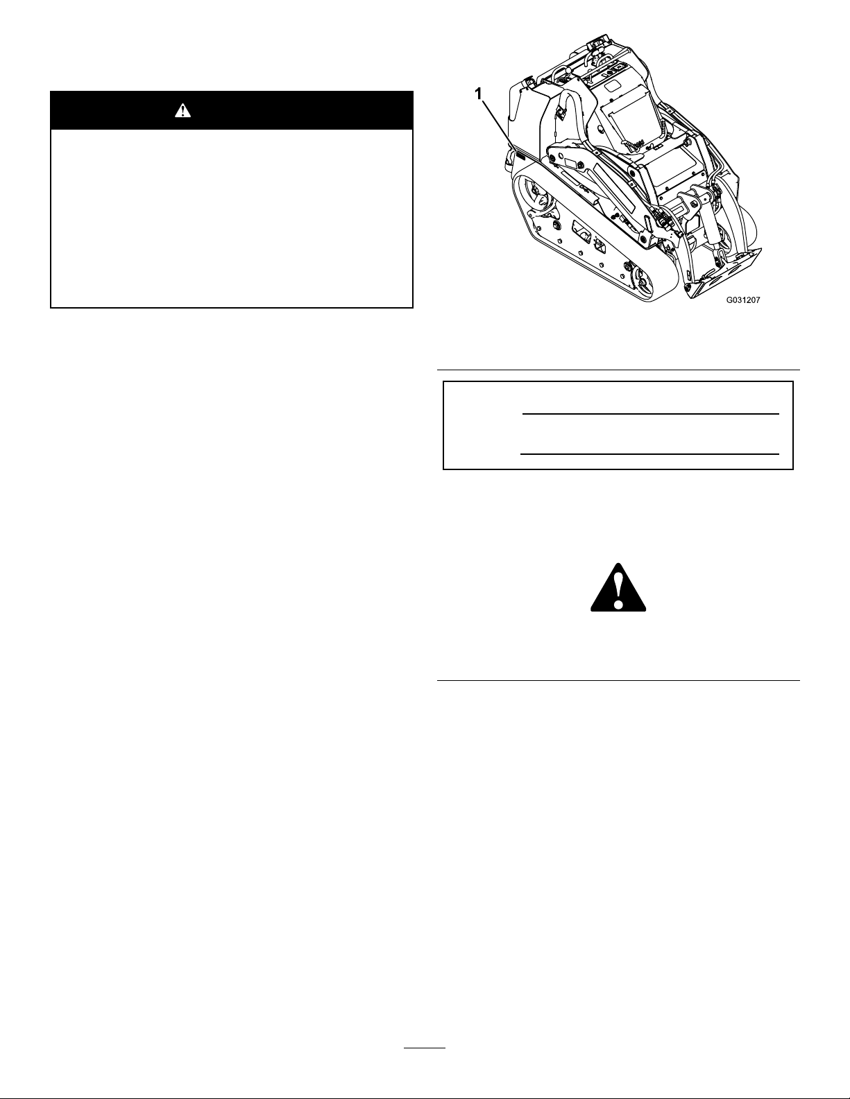
g031207
Figure1
1.Modelandserialnumberlocation
ModelNo.
SerialNo.
Thismanualidentiespotentialhazardsandhassafety
messagesidentiedbythesafety-alertsymbol(Figure2),
whichsignalsahazardthatmaycauseseriousinjuryordeath
ifyoudonotfollowtherecommendedprecautions.
Introduction
Thismachineisacompacttoolcarrierintendedtomove
variousearthandmaterialsforlandscapingandconstruction
work.Itisdesignedtooperateawidevarietyofattachments
eachofwhichperformaspecializedfunction.
Readthisinformationcarefullytolearnhowtooperateand
maintainyourproductproperlyandtoavoidinjuryand
productdamage.Youareresponsibleforoperatingthe
productproperlyandsafely.
YoumaycontactTorodirectlyatwww .Toro.comforproduct
safetyandoperationtrainingmaterials,accessoryinformation,
helpndingadealer,ortoregisteryourproduct.
Wheneveryouneedservice,genuineToroparts,oradditional
information,contactanAuthorizedServiceDealerorToro
CustomerServiceandhavethemodelandserialnumbersof
yourproductready.Figure1identiesthelocationofthe
modelandserialnumbersontheproduct.Writethenumbers
inthespaceprovided.
g000502
Figure2
1.Safety-alertsymbol
Thismanualuses2wordstohighlightinformation.
Importantcallsattentiontospecialmechanicalinformation
andNoteemphasizesgeneralinformationworthyofspecial
attention.
©2016—TheToro®Company
8111LyndaleAvenueSouth
Bloomington,MN55420
Contactusatwww.Toro.com.
2
PrintedintheUSA
AllRightsReserved
Page 3

Contents
Safety...........................................................................4
SafeOperatingPractices...........................................4
SoundPressureLevel...............................................6
SoundPower..........................................................6
VibrationLevel.......................................................6
StabilityData..........................................................7
SlopeIndicator.......................................................8
SafetyandInstructionalDecals.................................9
ProductOverview.........................................................13
Controls...............................................................13
MessageDisplay.................................................16
Specications........................................................17
Attachments/Accessories........................................17
Operation....................................................................18
ThinkSafetyFirst...................................................18
AddingFuel...........................................................18
FillingtheFuelTanks..............................................19
CheckingtheEngine-OilLevel.................................20
CheckingtheHydraulic-FluidLevel..........................20
CheckingtheEngineCoolant...................................21
BleedingtheFuelSystem.........................................22
StartingandShuttingOfftheEngine.........................22
StoppingtheMachine.............................................23
MovingaNon-functioningMachine.........................23
UsingAttachments.................................................24
SecuringtheMachineforTransport..........................25
LiftingtheMachine................................................25
Maintenance.................................................................26
RecommendedMaintenanceSchedule(s)......................26
Pre-MaintenanceProcedures......................................27
UsingtheCylinderLocks.........................................27
OpeningtheHood.................................................27
ClosingtheHood...................................................28
OpeningtheRear-AccessCover...............................28
RemovingtheFrontScreen......................................28
RemovingtheSideScreens......................................28
Lubrication...............................................................29
GreasingtheMachine.............................................29
EngineMaintenance..................................................30
ServicingtheAirCleaner.........................................30
ServicingtheEngineOil..........................................31
FuelSystemMaintenance...........................................32
CheckingtheFuelLinesandConnections..................32
DrainingtheFuelFilter/WaterSeparator...................33
ReplacingtheFuelFilterCanisterandIn-Line
Filter.................................................................33
DrainingtheFuelTanks..........................................33
ElectricalSystemMaintenance....................................34
ServicingtheBattery...............................................34
ServicingtheFuses.................................................36
DriveSystemMaintenance.........................................36
ServicingtheTracks................................................36
CoolingSystemMaintenance......................................39
ServicingtheCoolingSystem...................................39
BeltMaintenance......................................................40
CheckingtheAlternator/FanBeltTension.................40
ControlsSystemMaintenance.....................................40
HydraulicSystemMaintenance....................................41
ReplacingtheHydraulicFilter..................................41
ChangingtheHydraulicFluid...................................41
CheckingtheHydraulicLines...................................43
Cleaning...................................................................43
RemovingDebrisfromtheTractionUnit...................43
CleaningtheChassis...............................................44
Storage........................................................................44
Troubleshooting...........................................................45
Schematics...................................................................49
3
Page 4

Safety
Improperuseormaintenancebytheoperatororowner
canresultininjury.Toreducethepotentialforinjury,
complywiththesesafetyinstructionsandalways
payattentiontothesafety-alertsymbol,which
means:
instruction.Failuretocomplywiththeinstructionmay
resultinpersonalinjuryordeath.
SafeOperatingPractices
Thisproductiscapableofamputatinghandsandfeet.Always
followallsafetyinstructionstoavoidseriousinjuryordeath.
Engineexhaustcontainscarbonmonoxide,an
odorless,deadlypoisonthatcankillyou.
Donotruntheengineindoorsorinanenclosed
area.
Training
•ReadtheOperator'sManualandothertrainingmaterial.If
•Becomefamiliarwiththesafeoperationoftheequipment,
•Alloperatorsandmechanicsshouldbetrained.The
•Neverletchildrenoruntrainedpeopleoperateorservice
•Theowner/usercanpreventandisresponsiblefor
Preparation
•Evaluatetheterraintodeterminewhataccessoriesand
•Wearappropriateclothingincludinggloves,safetyglasses,
•Inspecttheareawheretheequipmentistobeusedand
•Useextracarewhenhandlingfuels.Theyareammable
Caution
,
W ar ning
,or
Danger
—personalsafety
WARNING
theoperator(s)ormechanic(s)cannotreadEnglish,itis
theowner'sresponsibilitytoexplainthismaterialtothem.
operatorcontrols,andsafetysigns.
ownerisresponsiblefortrainingtheusers.
theequipment.Localregulationsmayrestricttheageof
theoperator.
accidentsorinjuriesoccurringtohimselforherself,other
peopleorproperty.
attachmentsareneededtoproperlyandsafelyperform
thejob.Onlyuseaccessoriesandattachmentsapproved
bythemanufacturer.
longpants,substantialslip-resistantfootwear,andhearing
protection.Tiebacklonghairanddonotwearjewelry.
removeallobjectssuchasrocks,toys,andwirewhichcan
bethrownbythemachine.
andvaporsareexplosive.
–Useonlyanapprovedcontainer
–Neverremovethefuelcaporaddfuelwiththeengine
running.Allowtheenginetocoolbeforerefueling.
Donotsmoke.
–Neverrefuelordrainthemachineindoors.
•Checkthattheoperator'spresencecontrols,safety
switches,andshieldsareattachedandfunctioning
properly.Donotoperateunlesstheyarefunctioning
properly.
Operation
•Onlyoperateingoodlight,keepingawayfromholesand
hiddenhazards.
•Besurealldrivesareinneutralandparkingbrakeis
engagedbeforestartingtheengine.Starttheengineonly
fromtheoperator'sposition.
•Slowdownanduseextracareonhillsides.Besureto
travelintherecommendeddirectiononhillsides.Turf
conditionscanaffectthestabilityofthemachine.
•Slowdownandusecautionwhenmakingturns,crossing
roadsandsidewalks,andchangingdirectionsonslopes.
•Neveroperatewithouttheguardssecurelyinplace.Be
sureallinterlocksareattached,adjusted,andfunctioning
properly.
•Donotchangetheenginegovernorsettingoroverspeed
theengine.
•Keephandsandfeetawayfrommovingattachments.
•Lookbehindanddownbeforebackinguptobesureof
aclearpath.
•Nevercarrypassengersandkeeppetsandbystanders
away.
•Slowdownandusecautionwhenmakingturnsand
crossingroadsandsidewalks.
•Donotoperatethemachinewhenyouaretired,ill,or
undertheinuenceofalcoholordrugs.
•Usecarewhenloadingorunloadingthemachineintoa
trailerortruck.
•Usecarewhenapproachingblindcorners,shrubs,trees,
orotherobjectsthatmayobscurevision.
•Readallattachmentmanuals.
•Ensurethattheareaisclearofotherpeoplebefore
operatingthetractionunit.Stopthetractionunitif
anyoneentersthearea.
•Neverleavearunningtractionunitunattended.Always
lowertheloaderarms,shutofftheengine,settheparking
brake,andremovethekeybeforeleaving.
•Donotexceedtheratedoperatingcapacity,asthetraction
unitmaybecomeunstablewhichmayresultinlossof
control.
•Donotcarryaloadwiththearmsraised.Alwayscarry
loadsclosetotheground.
•Donotoverloadtheattachmentandalwayskeeptheload
levelwhenraisingtheloaderarms.Logs,boards,and
otheritemscouldrolldowntheloaderarms,injuringyou.
•Neverjerkthecontrols;useasteadymotion.
4
Page 5

•Watchfortrafcwhenoperatingnearorcrossing
roadways.
•Donottouchpartswhichmaybehotfromoperation.
Allowthemtocoolbeforeattemptingtomaintain,adjust,
orservice.
•Checkforoverheadclearances(i.e.,branches,doorways,
electricalwires)beforedrivingunderanyobjectsanddo
notcontactthem.
•Ensurethatyouoperatethetractionunitinareaswhere
therearenoobstaclesincloseproximitytotheoperator.
Failuretomaintainadequatedistancefromtrees,walls,
andotherbarriersmayresultininjury.Operatetheunit
onlyinareaswherethereissufcientclearanceforthe
operatortosafelymaneuvertheproduct.
•Beforedigging,havetheareamarkedforunderground
utilities,anddonotdiginmarkedareas.
Also,beawareofthelocationofobjectsandstructures
thatmaynotbemarked,suchasundergroundstorage
tanks,wells,andsepticsystems.
•Locatethepinchpointareasmarkedonthetractionunit
andattachmentsandkeephandsandfeetawayfrom
theseareas.
•Beforeoperatingthetractionunitwithanattachment,
ensurethattheattachmentisproperlyinstalledanda
genuineToroattachment.
•Lightningcancausesevereinjuryordeath.Iflightning
isseenorthunderisheardinthearea,donotoperate
themachine;seekshelter.
SlopeOperation
Slopesareamajorfactorrelatedtoloss-of-controland
tip-overaccidents,whichcanresultinsevereinjuryordeath.
Allslopesrequireextracaution.
•Donotoperatethetractionunitonhillsidesorslopes
exceedingtheanglesrecommendedinStabilityData(page
7),andthoseintheattachmentOperator'sManual.Seealso
theSlopeIndicator(page8).
•Operateupanddownslopeswiththeheavyendof
thetractionunituphill.Weightdistributionchanges.
Anemptybucketwillmaketherearofthetractionunit
theheavyend,andafullbucketwillmakethefrontofthe
tractionunittheheavyend.Mostotherattachmentswill
makethefrontoftractionunittheheavyend.
•Raisingtheloaderarmsonaslopewillaffectthestability
ofthemachine.Wheneverpossible,keeptheloaderarms
intheloweredpositionwhenonslopes.
•Removeoraddattachmentsonlevelground.
•Removeobstaclessuchasrocks,treelimbs,etc.fromthe
workarea.Watchforholes,ruts,orbumps,asuneven
terraincouldoverturnthetractionunit.Tallgrasscan
hideobstacles.
•UseonlyT oro-approvedattachments.Attachmentscan
changethestabilityandtheoperatingcharacteristicsof
thetractionunit.Warrantymaybevoidedifusedwith
unapprovedattachments.
•Keepallmovementsonslopesslowandgradual.Donot
makesuddenchangesinspeedordirection.
•Avoidstartingorstoppingonaslope.Ifthetractionunit
losestraction,proceedslowly,straightdowntheslope.
•Avoidturningonslopes.Ifyoumustturn,turnslowly
andkeeptheheavyendofthetractionunituphill.
•Donotoperateneardrop-offs,ditches,orembankments.
Thetractionunitcouldsuddenlyturnoverifatrackgoes
overtheedgeofaclifforditch,orifanedgecavesin.
•Usecautionwhenoperatingonwetgrass.Reduced
tractioncouldcausesliding.
•Donotparkthetractionunitonahillsideorslope
withoutloweringtheattachmenttothegroundand
settingtheparkingbrake.
MaintenanceandStorage
•Parkonlevelground,disengagetheauxiliaryhydraulics,
lowertheattachment,settheparkingbrake,shutoffthe
engine,andremovethekey.Waitforallmovementto
stopandthemachinetocoolbeforeadjusting,cleaning,
storing,orrepairing.
•Cleandebrisfromattachments,drives,mufers,and
enginetohelppreventres.Cleanupoilorfuelspillage.
•Donotstorefuelnearamesordrainindoors.
•Neverallowuntrainedpersonneltoservicethemachine.
•Usejackstandstosupportcomponentswhenrequired.
•Carefullyreleasepressurefromcomponentswithstored
energy.
•Disconnectthebatterybeforemakinganyrepairs;refer
toUsingtheBattery-DisconnectSwitch(page34).
•Keephandsandfeetawayfrommovingparts.Ifpossible,
donotmakeadjustmentswiththeenginerunning.
•Chargebatteriesinanopen,well-ventilatedarea,away
fromsparkandames.Unplugthechargerbefore
connectingordisconnectingitfromthebattery.Wear
protectiveclothinganduseinsulatedtools.
•Keepallpartsingoodworkingconditionandallhardware
tightened.Replaceallwornordamageddecals.
•Ifanymaintenanceorrepairrequirestheloaderarmsto
beintheraisedposition,securethearmsintheraised
positionwiththehydrauliccylinderlock.
•Securetheloaderarmvalvewiththeloadervalvelock
anytimeyouneedtostopthemachinewiththeloader
armsraised.
•Keepnutsandboltstight.Keepequipmentingood
condition.
•Nevertamperwithsafetydevices.
•Keepthetractionunitfreeofgrass,leaves,orotherdebris
build-up.Cleanupoilorfuelspillage.Allowthetraction
unittocoolbeforestoring.
5
Page 6

•Useextracarewhenhandlingfuels.Theyareammable
andvaporsareexplosive.
–Useonlyanapprovedcontainer.
–Neverremovethefuelcaporaddfuelwhenthe
engineisrunning.Allowtheenginetocoolbefore
refueling.Donotsmoke.
–Neverrefuelthetractionunitindoors.
SoundPressureLevel
SoundPressureLevelThisunithasasoundpressurelevelat
theoperator’ searof86dBA,whichincludesanUncertainty
Value(K)of0.6dBA.
Soundpressurelevelwasdeterminedaccordingtothe
proceduresoutlinedinISO6396.
–Neverstorethetractionunitorfuelcontainerinside
wherethereisanopename,suchasnearawater
heaterorfurnace.
–Neverllacontainerwhileitisinsideavehicle,trunk,
pick-upbed,oranysurfaceotherthantheground.
–Keepcontainernozzleincontactwiththetankduring
lling.
•Stopandinspecttheequipmentifyoustrikeanobject.
Makeanynecessaryrepairsbeforerestarting.
•UseonlygenuineT ororeplacementpartstoensurethat
originalstandardsaremaintained.
•Batteryacidispoisonousandcancauseburns.Avoid
contactwithskin,eyes,andclothing.Protectyourface,
eyes,andclothingwhenworkingwithabattery.
•Batterygasescanexplode.Keepcigarettes,sparksand
amesawayfromthebattery.
•Keepyourbodyandhandsawayfrompinholeleaks
ornozzlesthatejecthigh-pressurehydraulicuid.Use
cardboardorpapertondhydraulicleaks;neveruse
yourhands.Hydraulicuidescapingunderpressurecan
penetrateskinandcauseinjuryrequiringsurgerywithin
afewhoursbyaqualiedsurgeon;otherwisegangrene
mayresult.
SoundPower
Thisunithasaguaranteedsoundpowerlevelof101dBA,
basedonmeasurementsofidenticalmachinesperISO6395.
VibrationLevel
Hand-Arm
Measuredvibrationlevelforrighthand=0.7m/s
Measuredvibrationlevelforlefthand=0.7m/s
UncertaintyValue(K)=0.3m/s
Measuredvaluesweredeterminedaccordingtotheprocedures
outlinedinENISO20643.
2
WholeBody
Measuredvibrationlevel=0.29m/s
UncertaintyValue(K)=0.15m/s
Measuredvaluesweredeterminedaccordingtotheprocedures
outlinedinENISO20643.
2
2
2
2
6
Page 7
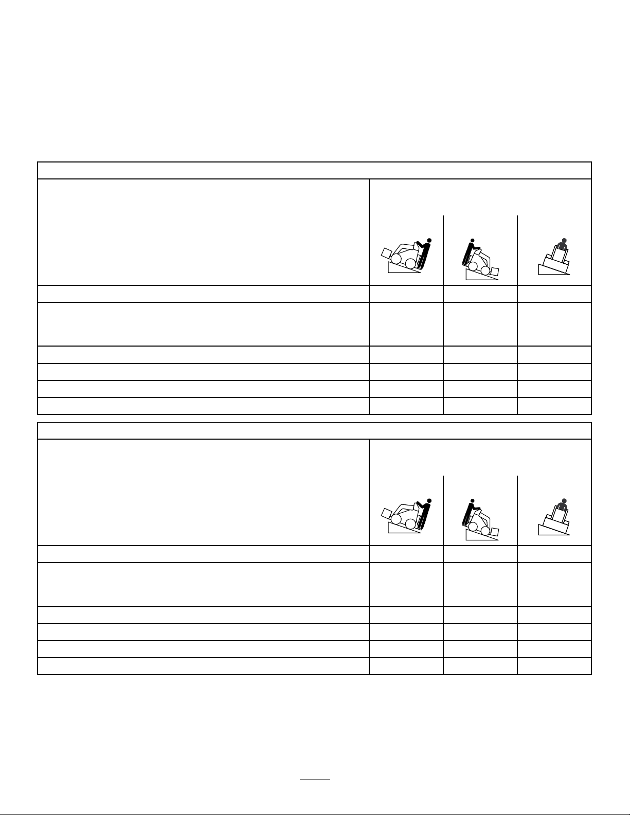
StabilityData
Thefollowingtableslistthemaximumsloperecommendedforthetractionunitinthepositionslistedinthetables.Slopesover
thelisteddegreemaycausethetractionunittobecomeunstable.Thedatainthetablesassumethattheloaderarmsarefully
lowered;raisedarmsmayaffectthestability.
Ineachattachmentmanualisasetofthreestabilityratings,oneforeachhillposition.Todeterminethemaximumslopeyou
cantraversewiththeattachmentinstalled,ndthedegreeofslopethatcorrespondstothestabilityratingsoftheattachment.
Example:IftheattachmentinstalledonaTXModel22327tractionunithasafrontuphillratingofB,arearuphillratingof
D,andasideuphillratingofC,thenyoucoulddriveforwardupa19°slope,rearwardupa11°slope,orsidewaysona11°
slope,aslistedinthefollowingtable.
Model22327
MaximumRecommendedSlopewhen
Operatingwith:
FrontUphillRearUphill
Conguration
Tractionunitwithoutattachment
Tractionunitwithanattachmentratedwithoneofthefollowingstabilityratings
foreachslopeposition:*
A
B
C16°17°11°
D
E
Model22328
15°19°16°
25°25°20°
19°20°15°
14°11°8°
5°5°5°
MaximumRecommendedSlopewhen
Operatingwith:
FrontUphillRearUphill
SideUphill
SideUphill
Conguration
Tractionunitwithoutattachment
Tractionunitwithanattachmentratedwithoneofthefollowingstabilityratings
foreachslopeposition:*
A
B
C18°15°14°
D
E
16°19°19°
25°25°23°
21°19°18°
15°10°10°
5°5°5°
7
Page 8
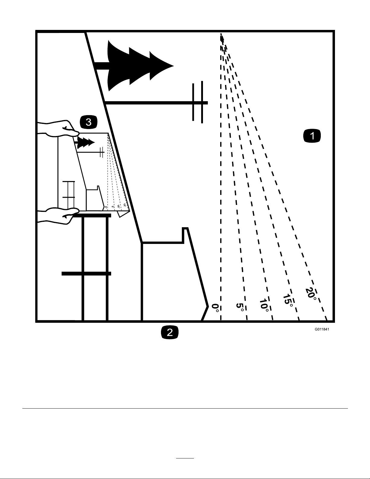
SlopeIndicator
G011841
Figure3
Thispagemaybecopiedforpersonaluse.
1.Todeterminethemaximumslopeyoucansafelyoperatethemachineon,refertotheStabilityDatasection.Usetheslope
indicatortodeterminethedegreeofslopeofhillsbeforeoperating.Donotoperatethismachineonaslopegreaterthanthat
speciedintheStabilityDatasection.Foldalongtheappropriatelinetomatchtherecommendedslope.
2.Alignthisedgewithaverticalsurface,atree,building,fencepole,etc.
3.Exampleofhowtocompareslopewithfoldededge
8
g011841
Page 9
SafetyandInstructionalDecals
Safetydecalsandinstructionsareeasilyvisibletotheoperatorandarelocatednearanyareaofpotential
danger.Replaceanydecalthatisdamagedorlost.
93-6681
1.Cutting/dismembermenthazard,fan—stayawayfrom
movingparts.
decal93-6681
decal115-2047
115-2047
1.Warning—donottouchthehotsurface.
93-7814
1.Entanglementhazard,belt—stayawayfrommovingparts.
93-9084
1.Liftpoint
2.Tie-downpoint
decal93-7814
decal115-4855
115-4855
1.Hotsurface/burnhazard—wearprotectivegloveswhen
handlingthehydrauliccouplersandreadtheOperator's
Manualforinformationonhandlinghydrauliccomponents.
decal115-4858
115-4858
decal93-9084
1.Crushinghazardofhandsorfeet—installthecylinderlock.
decal115-4865
115-4865
1.Enginecoolant
2.ReadtheOperator's
Manual.
1.Enginecoolantunder
pressure
2.Explosionhazard—read
theOperator'sManual.
117-3276
3.Warning—donottouchthe
hotsurface.
4.Warning—readthe
Operator'sManual.
decal117-3276
decal117-2718
117-2718
9
Page 10
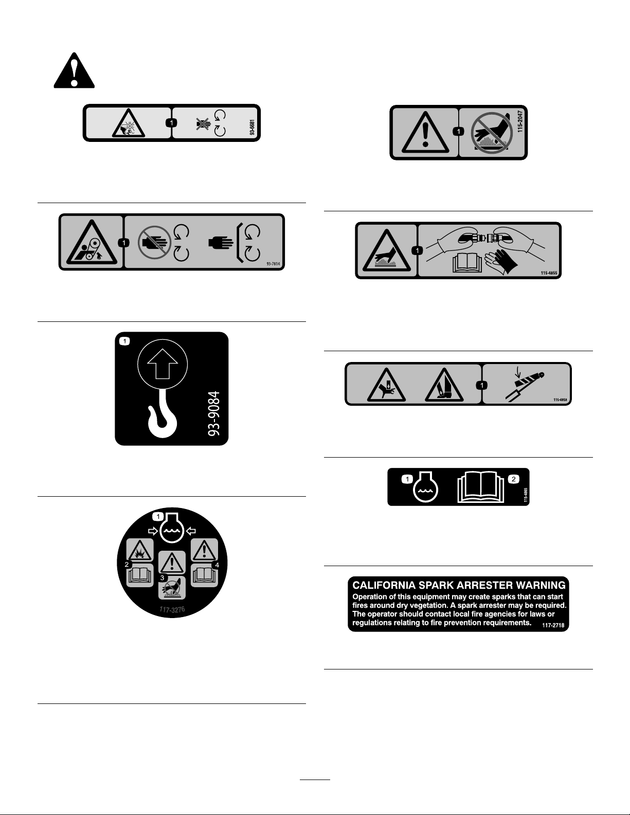
120-0625
1.Pinchpoint,hand—keephandsaway .
130-2836
1.Crushinghazard;cuttinghazard—keepawayfromthe
bucketandtheliftarm.
decal120-0625
decal131-0711
131-0711
1.Crushinghazard—keepawayfrompinchpointsand
actuatingparts.
decal130-2836
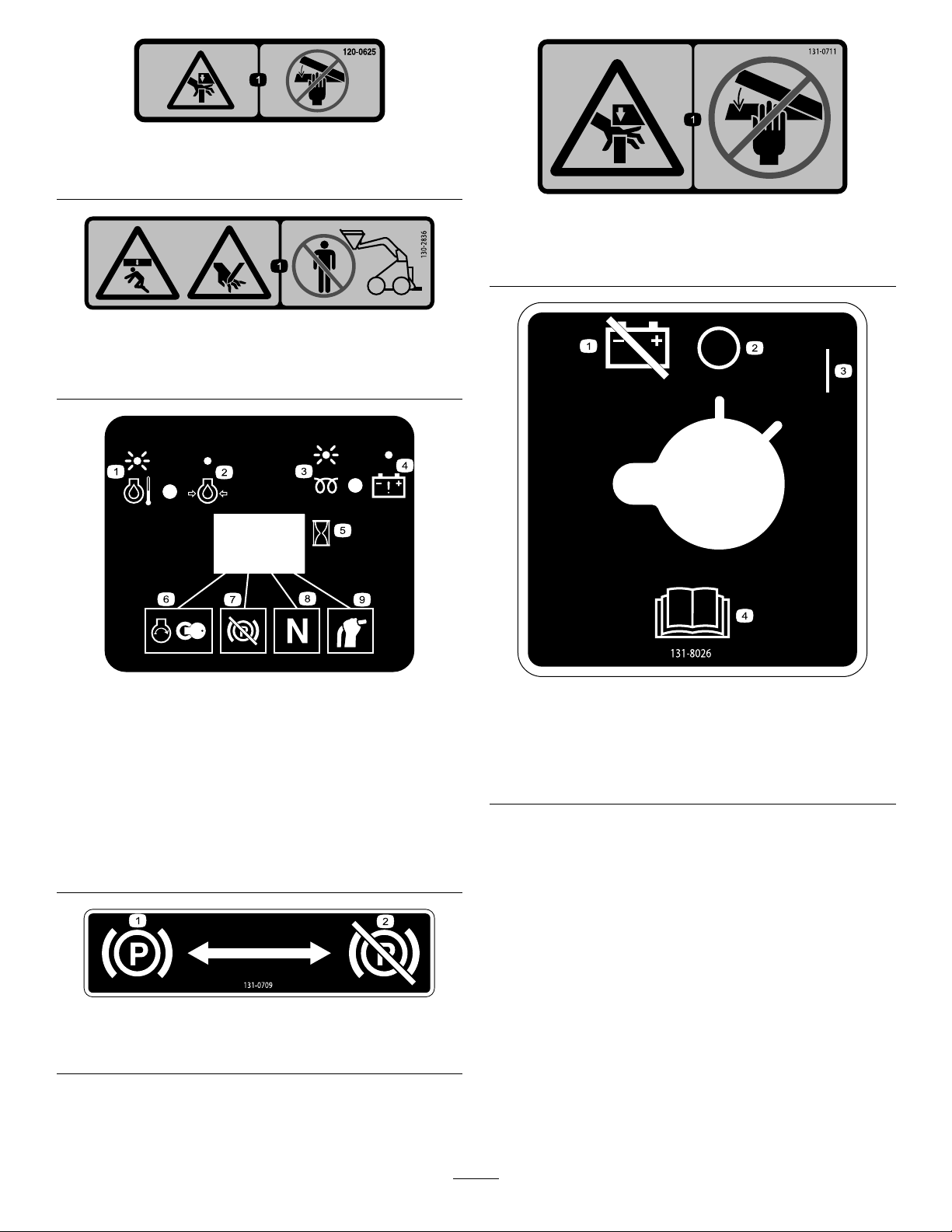
130-7637
1.Blinking
light—engine-coolant
temperature
2.Steadylight—engine-oil
pressure
3.Blinkinglight—glowplug8.Tractionneutral
4.Steadylight—battery
warning
5.Hourmeter
6.Enginestart
7.Parkingbrakedisengaged
9.Auxiliaryleverneutral
131-0709
1.Parkingbrake—engage2.Parkingbrake—disengage
decal130-7637
decal131-8026
131-8026
1.Battery
power—disconnect
2.On4.ReadtheOperator's
decal131-0709
3.Off
Manual.
10
Page 11
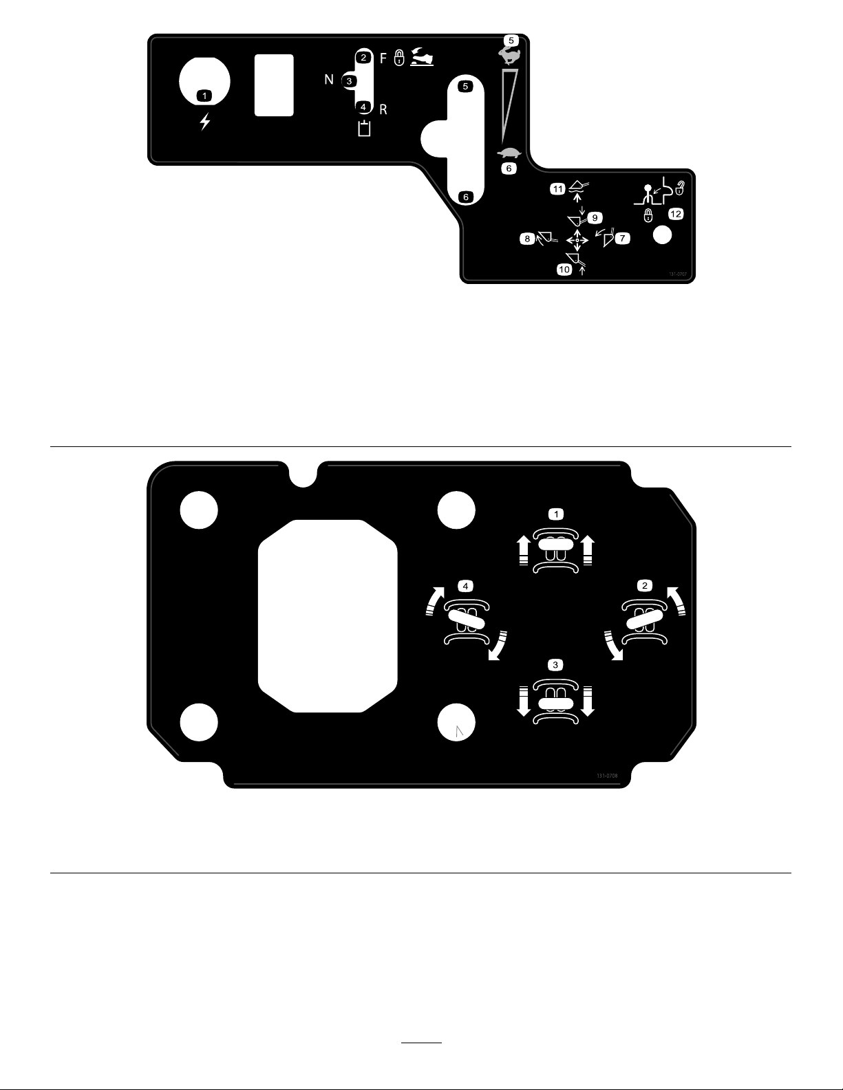
decal131-0707
131-0707
1.12Vpowersocket
2.Hydraulicattachment—forwardoperation
7.Tilttheattachmentforward.
8.Tilttheattachmentrearward.
3.Hydraulicattachment—neutralposition9.Lowertheattachment.
4.Hydraulicattachment—reverseoperation10.Raisetheattachment.
5.Enginespeed—fast11.Movetheattachmenttoaoatposition.
6.Enginespeed—slow12.Leverlock
1.Moveforward
2.Turnright
decal131-0708
131-0708
3.Moverearward
4.Turnleft
11
Page 12
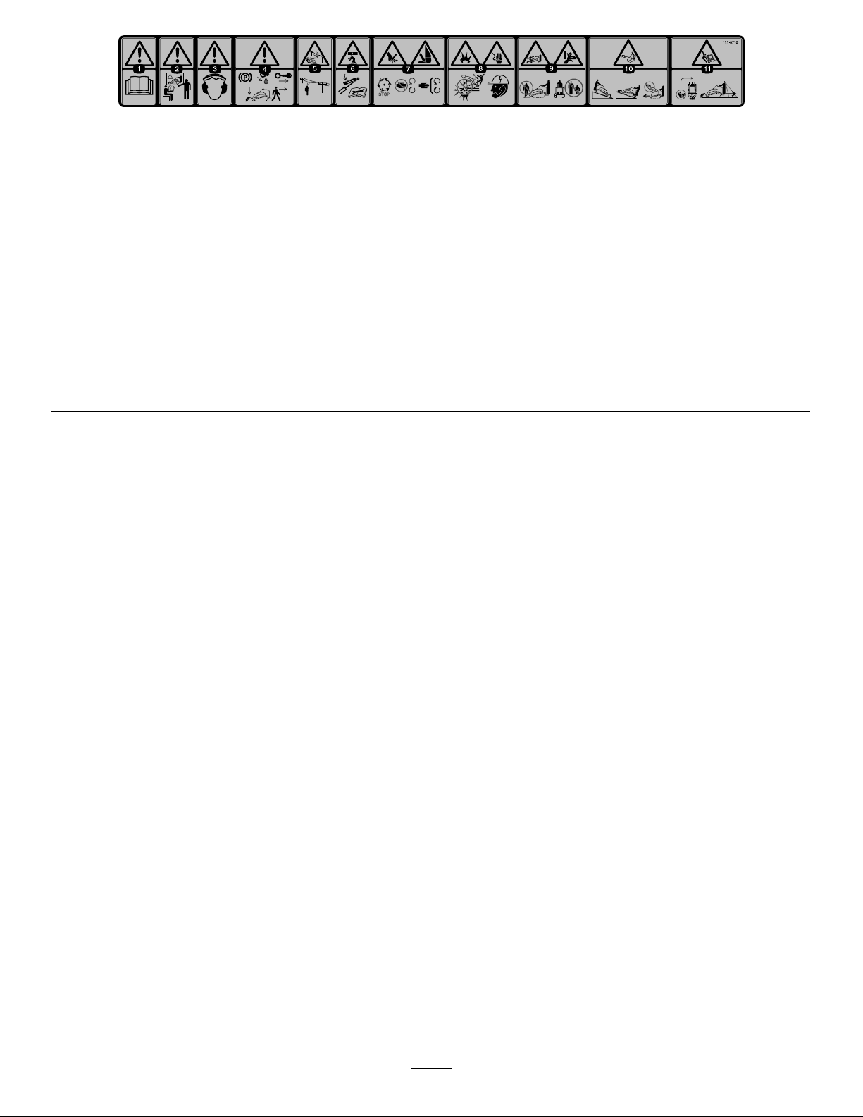
decal131-0710
131-0710
1.Warning—readtheOperator'sManual.7.Cutting/severinghazardofhandorfoot—waitforallmoving
partstostopbeforeservicing;keepawayfrommovingparts;
keepallguardsandshieldsinplace.
2.Warning—receivetrainingbeforeoperatingthemachine.
8.Explosionhazard;electrocutionhazard—callthelocalutilities
hotlinebeforebeginningworkinanarea.
3.Warning—wearhearingprotection.
9.Crushinghazard—keepawayfromthebucketwhenoperating
themachine;keepbystandersawayfromthemachine.
4.Warning—engagetheparkingbrake,lowerthebuckettothe
ground,shutofftheengine,andremovethekeyfromthe
ignitionbeforeleavingthemachine.
10.Tippinghazard—alwaysmoveupordownslopeswiththe
bucketlowered;neverdriveonaslopewiththebucketraised;
alwaysoperatewiththeheavyenduphill;alwayscarryloads
low;neverjerkthecontrollevers;useasteady ,evenmotion..
5.Electrocutionhazard,powerlines—checkforpowerlinesin
theareabeforeusingthemachine.
11.Tippinghazard—donotmakefastturns;alwayscheckbehind
youbeforereversingthemachine.
6.Crushinghazard—keepawayfrompinchpoints;read
theOperator'sManualbeforeservicingorperforming
maintenance.
12
Page 13
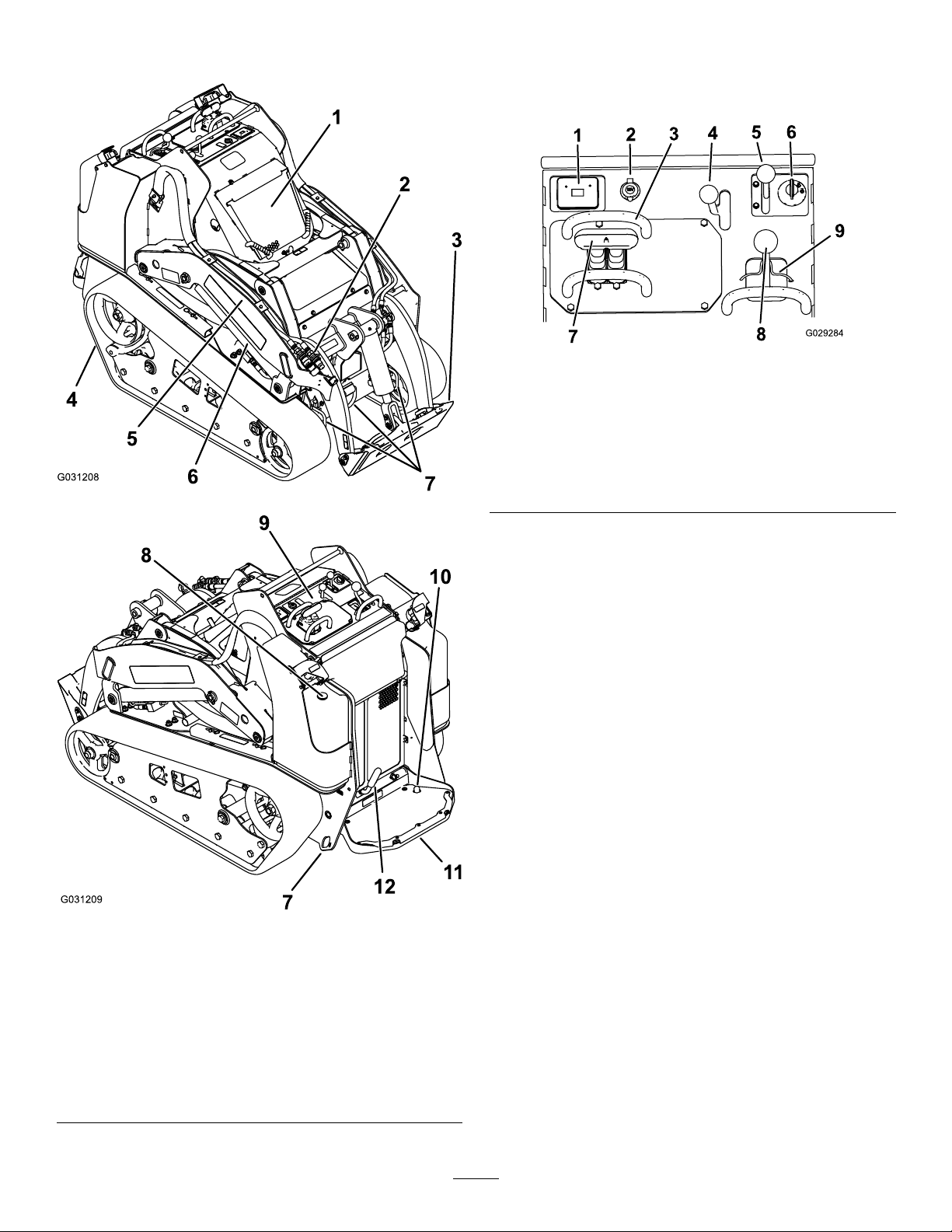
ProductOverview
Controls
Becomefamiliarwithallthecontrols(Figure5)beforeyou
starttheengineandoperatethetractionunit.
g029284
Figure5
1.Messagedisplay6.Keyswitch
2.Powersocket7.Tractioncontrol
3.Referencebar8.Loaderarm/attachment-tilt
4.Auxiliary-hydraulicslever9.Loaderlock
g031208
5.Throttlelever
lever
1.Hood
2.Auxiliary-hydraulic
couplers
3.Mountplate
4.Track10.Auxiliary-hydraulics-lock
5.Loaderarm
6.Liftcylinder
Figure4
7.Tie-down/liftloop
8.Fuelgauge
9.Controlpanel
switch
11.Operatorplatform
12.Parkingbrake
KeySwitch
Thekeyswitch,usedtostartandshutofftheengine,has3
positions:OFF,RUN,andSTART.
Tostarttheengine,rotatethekeytotheSTARTposition.
Releasethekeywhenenginestartsanditmovesautomatically
totheRUNposition.
Toshutofftheengine,rotatethekeytotheOFFposition.
ThrottleLever
Movethecontrolforwardtoincreasetheenginespeedand
rearwardtodecreasespeed.
ReferenceBar
Whendrivingthetractionunit,usethereferencebaras
g031209
ahandleandaleveragepointforcontrollingthetraction
controlandtheauxiliary-hydraulicslever.T oensuresmooth,
controlledoperation,donottakebothhandsoffthereference
barwhileoperatingthemachine.
13
Page 14
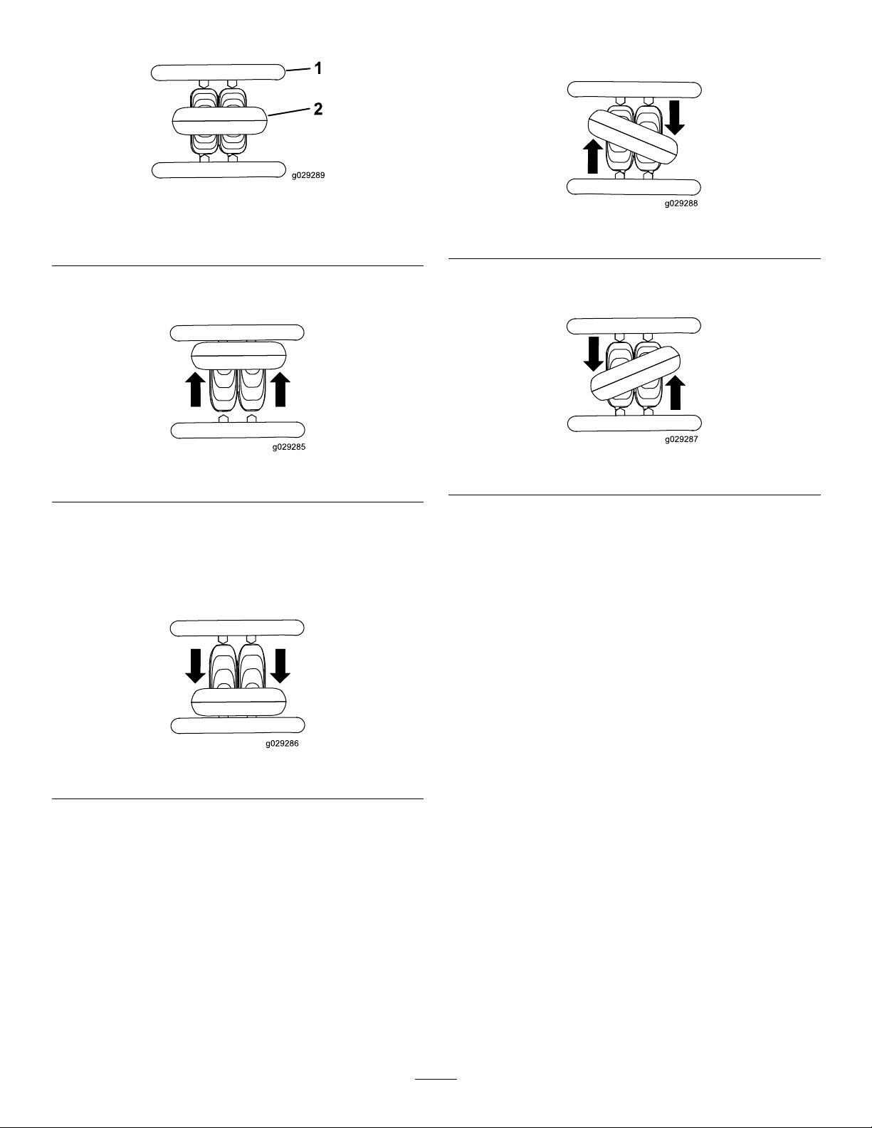
TractionControl
1.Referencebar
2.Tractioncontrol
•Toturnright,rotatethetractioncontrolclockwise(Figure
9).
g029289
Figure6
g029288
Figure9
•Tomoveforward,movethetractioncontrolforward
(Figure7).
Figure7
•Tomoverearward,movethetractioncontrolrearward
(Figure8).
Important:Whenreversing,lookbehindyoufor
obstructionsandkeepyourhandsonthereference
bar.
•Toturnleft,rotatethetractioncontrolcounterclockwise
(Figure10).
g029285
Figure10
g029287
•Tostopthemachine,releasethetractioncontrol(Figure
6).
Note:Thefartheryoumovethetractioncontrolinany
direction,thefasterthemachinemovesinthatdirection.
Figure8
g029286
14
Page 15
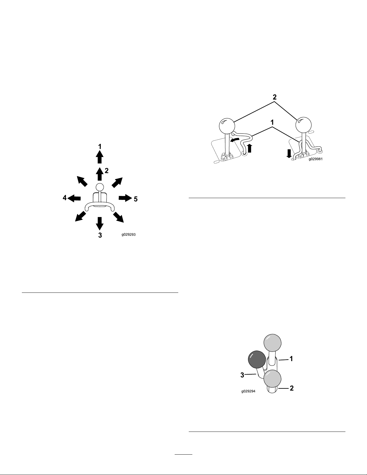
LoaderArm/Attachment-TiltLever
LoaderLock
•Totilttheattachmentforward,slowlymovetheleverto
theright(Figure11).
•Totilttheattachmentrearward,slowlymovethelever
totheleft(Figure11).
•Tolowertheloaderarms,slowlymovetheleverforward
(Figure11).
•Toraisetheloaderarms,slowlymovetheleverrearward
(Figure11).
•Tolowertheloaderarmstoadetent(oat)position,push
theleverfullyforward(Figure11).
Note:Thisallowsattachmentssuchasthelevelerand
thehydraulicbladetofollowthecontoursoftheground
(i.e.,oat)whengrading.
Theloaderlocksecurestheloaderarm/attachment-tiltlever
sothatyoucannotpushitforward.Thisensuresthatno
oneaccidentallylowerstheloaderarmsduringmaintenance.
Securetheloaderarmswiththelockanytimeyouneedto
stopthemachinewiththeloaderarmsraised.
Tosetthelock,liftuponitsoitclearstheholeinthecontrol
panelandswingittotheleft,infrontoftheloader-armlever,
pushingitdownintothelockedposition(Figure12).
g029981
Figure12
1.Loaderarm/attachment-tilt
lever
2.Loaderlock
Figure11
1.Detent(oat)position
2.Lowertheloaderarms.5.Tilttheattachment
3.Raisetheloaderarms.
4.Tilttheattachment
rearward.
forward.
Bymovingthelevertoanintermediateposition(e.g.,
forwardandleft),youcanmovetheloaderarmsandtiltthe
attachmentatthesametime.
Loader-ControlReferenceBar
Theloader-controlreferencebarhelpsstabilizeyourhand
whileoperatingtheloaderarm/attachmenttiltlever(Figure
g029293
4).
Auxiliary-HydraulicsLever
Tooperateahydraulicattachmentintheforwarddirection,
movetheauxiliary-hydraulicsleverforward(Figure13).
Tooperateahydraulicattachmentinreversedirection,move
thehydraulicsleverrearward(Figure13).
IfyoureleasetheleverwhileintheFORW ARDorREVERSE
position,theleverautomaticallyreturnstotheNEUTRAL
position(Figure13).
15
1.Forwardowhydraulics
2.Reverseowhydraulics
g029294
Figure13
3.Neutral
Page 16
Auxiliary-Hydraulics-LockSwitch
Engine-OilPressure
Presstheauxiliary-hydraulics-lockswitchtolockthe
auxiliary-hydraulicsleverintheFORWARDpositionandfree
yourhandforothercontrols(Figure5).
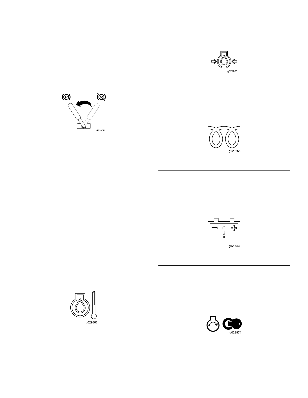
ParkingBrakeLever
Tosettheparkingbrake,rotatethebrakelevertoleft(Figure
14).
Note:Thetractionunitmayrollslightlybeforethebrakes
engageinthedrivesprocket.
Figure14
Toreleasethebrake,rotatethebrakelevertotheright.
Note:Youmayneedtoadjustthetractioncontroltorelease
thebrakepinsandrotatethelever.
Iftheengine-oil-pressurebecomestoolow ,thelightonthe
leftilluminatessteadily(Figure16).Ifthishappens,shutoff
theengineimmediatelyandchecktheoil.Iftheoillevelis
low,addoiland/orlookforpossibleleaks.
g029665
Figure16
GlowPlug
Thelightontherightasheswhiletheglowplugsarecharged
andwarmingtheengine(Figure17).
g030721
g029668
Figure17
FuelGauge
Thisgaugemeasurestheamountoffuelinthefueltanks
(Figure4).
MessageDisplay
Engine-CoolantT emperature
Iftheenginecoolantbecomestoohot,thelightontheleft
ashesandthehornsounds(Figure15).Ifthishappens,
disengagetheauxiliaryhydraulicsandletthemachinerunat
highidletoallowthecoolingsystemtocoolthemachine.
Checkthecoolantlevelwhentheenginehasfullycooled.
Important:Donotshutofftheengine,asthismay
causethemachinetooverheat.
Figure15
Battery-ChargeIndicatorLight
Ifthebatterychargebecomestoolow ,thelightontheright
illuminatessteadily(Figure18).Ifthishappens,shutoffthe
engineandchargeorreplacethebattery.RefertoServicing
theBattery(page34)
g029667
Figure18
HourMeter
Thehourmeterdisplaysthenumberofhoursofoperation
thathavebeenloggedonthetractionunitandthefollowing
indicators:
•Enginestart—displayswhenyoustarttheengine
g029666
g029974
Figure19
16
Page 17

•Parkingbrake—displayswhenyoudisengagetheparking
brake
Specications
Note:Specicationsanddesignaresubjecttochange
withoutnotice.
Figure20
•Tractionneutral—displayswhenthetractioncontrolis
intheNEUTRALposition
Figure21
•Auxiliaryleverneutral—displayswhentheauxiliarylever
isintheNEUTRALposition
Figure22
g030520
g029211
g029975
Model22327
Width
Length
Height
Weight
Operatingcapacity(withstandard
bucket)
Tippingcapacity(withstandardbucket)1296kg(2,857lb)
Wheelbase
Dumpheight(withstandardbucket)155cm(61inches)
Reach—fullyraised(withstandard
bucket)
Heighttohingepin(withstandard
bucketinhighestposition)
Model22328
Width
Length
Height
Weight
Operatingcapacity(withstandard
bucket)
Tippingcapacity(withstandardbucket)1296kg(2,857lb)
Wheelbase
Dumpheight(withstandardbucket)155cm(61inches)
Reach—fullyraised(withstandard
bucket)
Heighttohingepin(withstandard
bucketinhighestposition)
85cm(33inches)
256cm(101inches)
138cm(54inches)
1234kg(2,720lb)
454kg(1,000lb)
104cm(41inches)
62cm(25inches)
206cm(81inches)
103cm(41inches)
256cm(101inches)
138cm(54inches)
1297kg(2,860lb)
454kg(1,000lb)
104cm(41inches)
62cm(25inches)
206cm(81inches)
Attachments/Accessories
AselectionofToroapprovedattachmentsandaccessoriesis
availableforusewiththemachinetoenhanceandexpand
itscapabilities.ContactyourAuthorizedServiceDealeror
Distributororgotowww .Toro.comforalistofallapproved
attachmentsandaccessories.
Important:UseonlyToro-approvedattachments.
Otherattachmentsmaycreateanunsafeoperating
environmentordamagethetractionunit.
17
Page 18

Operation
G009027
1
2
Note:Determinetheleftandrightsidesofthemachine
fromthenormaloperatingposition.
Important:Beforeoperating,checkthefuelandoil
level,andremovedebrisfromthetractionunit.Ensure
thattheareaisclearofpeopleanddebris.Youshould
alsoknowandhavemarkedthelocationsofallutility
lines.
ThinkSafetyFirst
Carefullyreadallsafetyinstructionsandsymbolsinthe
safetysection.Knowingthisinformationcouldhelpyouor
bystandersavoidinjury.
CAUTION
Thismachineproducessoundlevelsthatcancause
hearinglossthroughextendedperiodsofexposure.
Wearhearingprotectionwhenoperatingthis
machine.
AddingFuel
Useonlyclean,freshdieselfuelorbiodieselfuelswithlow
(<500ppm)orultralow(<15ppm)sulfurcontent.The
minimumcetaneratingshouldbe40.Purchasefuelin
quantitiesthatcanbeusedwithin180daystoensurefuel
freshness.
Fueltankcapacity:41L(11USgallons)
Usesummer-gradedieselfuel(No.2-D)attemperatures
above-7°C(20°F)andwintergrade(No.1-DorNo.
1-D/2-Dblend)belowthattemperature.Usingwinter-grade
fuelatlowertemperaturesprovideslowerashpointand
coldowcharacteristics,whicheasesstartingandreduces
fuellterplugging.
Usingsummer-gradefuelabove-7°C(20°F)contributes
towardlongerfuelpumplifeandincreasedpowercompared
towinter-gradefuel.
Important:Donotusekeroseneorgasolineinsteadof
dieselfuel.Failuretoobservethiscautionwilldamage
theengine.
WARNING
Useprotectiveequipmentforyoureyes,ears,hands,feet,
andhead.
Figure23
1.Weareyeprotection.2.Wearhearingprotection.
Fuelisharmfulorfatalifswallowed.Long-term
exposuretovaporscancauseseriousinjuryand
illness.
•Avoidprolongedbreathingofvapors.
•Keepfaceawayfromnozzleandfueltankor
conditioneropening.
•Keepfuelawayfromeyesandskin.
g009027
BiodieselReady
Thismachinecanalsouseabiodieselblendedfuelofup
toB20(20%biodiesel,80%petrodiesel).Thepetrodiesel
portionshouldbeloworultralowsulfur.Observethe
followingprecautions:
•Thebiodieselportionofthefuelmustmeetspecication
ASTMD6751orEN14214.
•TheblendedfuelcompositionshouldmeetASTMD975
orEN590.
•Paintedsurfacesmaybedamagedbybiodieselblends.
•UseB5(biodieselcontentof5%)orlesserblendsincold
weather.
•Monitorseals,hoses,gasketsincontactwithfuelasthey
maybedegradedovertime.
•Fuellterpluggingmaybeexpectedforatimeafter
convertingtobiodieselblendsd.
•Contactyourdistributorifyouwishformoreinformation
onbiodiesel.
18
Page 19

FillingtheFuelTanks
DANGER
Incertainconditions,fuelisextremelyammable
andhighlyexplosive.Areorexplosionfromfuel
canburnyouandothersandcandamageproperty.
•Fillthefueltanksoutdoors,inanopenarea,
whentheengineiscold.Wipeupanyfuelthat
spills.
•Neverllthefueltanksinsideanenclosed
trailer.
•Neversmokewhenhandlingfuelandstayaway
fromanopenameorwherefuelfumesmaybe
ignitedbyaspark.
•Storefuelinanapprovedcontainerandkeepit
outofthereachofchildren.Neverbuymore
thana30-daysupplyoffuel.
•Donotoperatewithoutentireexhaustsystemin
placeandinproperworkingcondition.
FillthefueltanksasshowninFigure24.
Note:Thefuel-tankcapsclickwhenyouclosethemsecurely.
Usethebracketstolockthefueltanks.
DANGER
Incertainconditionsduringfueling,static
electricitycanbereleased,causingasparkthatcan
ignitethefuelvapors.Areorexplosionfromfuel
canburnyouandothersandcandamageproperty.
•Alwaysplacefuelcontainersonthegroundaway
fromyourvehiclebeforelling.
•Donotllfuelcontainersinsideavehicleoron
atruckortrailerbed,becauseinteriorcarpets
orplastictruckbedlinersmayinsulatethe
containerandslowthelossofanystaticcharge.
•Whenpractical,removeequipmentfromthe
truckortrailerandrefueltheequipmentwithits
wheelsontheground.
•Ifthisisnotpossible,thenrefuelsuchequipment
onatruckortrailerfromaportablecontainer
ratherthanfromafuel-dispensernozzle.
•Ifyoumustuseafuel-dispensernozzle,keepthe
nozzleincontactwiththerimofthefueltank
orcontaineropeningatalltimesuntilfuelingis
complete.
g029669
Figure24
19
Page 20

CheckingtheEngine-OilLevel
CheckingtheHydraulic-Fluid
ServiceInterval:Beforeeachuseordaily
1.Parkthetractionunitonalevelsurface,lowerthe
loaderarms,andshutofftheengine.
2.Removethekeyandallowtheenginetocool.
3.Openthehoodandsecurethehoodprop.
4.Cleanaroundtheoildipstickandoil-llercap(Figure
25).
Figure25
1.Oil-llercap2.Oildipstick
Level
ServiceInterval:Every25hours
HydraulicTankCapacity:37.9L(10USgallons)
RefertoChangingtheHydraulicFluid(page41)forhydraulic
uidspecications.
Important:Alwaysusethecorrecthydraulicuid.
Unspecieduidswilldamagethehydraulicsystem.
1.Removetheattachment,ifoneisinstalled;referto
RemovinganAttachment(page25).
2.Parkthemachineonalevelsurface.
3.Raisetheloaderarmsandinstallthecylinderlocks;
refertoInstallingtheCylinderLocks(page27).
4.Shutofftheengineandremovethekey.
5.Openthehoodandsecurethehoodprop.
6.Removetherightsidescreen;refertoRemovingthe
g029940
SideScreens(page28).
7.Cleantheareaaroundthellerneckofthehydraulic
tank(Figure27).
5.Checktheoilandaddadditionaloilasneeded(Figure
26).
Important:Donotoverllthecrankcasewithoil
becausetheenginemaybedamaged.
g029748
Figure27
1.Hydraulicller-neckcap
8.Removethecapfromthellerneckandchecktheuid
levelonthedipstick(Figure28).
Note:Theuidlevelshouldbebetweenthe2notches
ofthedipstickwhilethearmsareloweredoratthe
lowernotchwhilethearmsareraised.
Figure26
g029301
20
Page 21

Figure28
1.Fillerneck2.Dipstick
9.Ifthelevelislow ,addenoughuidtoraiseittothe
properlevel.
10.Installthecaponthellerneck.
11.Installthesidescreen.
DANGER
Rotatingshaftandfancancausepersonalinjury.
•Donotoperatethemachinewithoutthecovers
inplace.
•Keepngers,hands,andclothingclearof
rotatingfananddriveshaft.
•Shutofftheengineandremovetheignitionkey
beforeperformingmaintenance.
1.Checkthelevelofcoolantintheexpansiontank
(Figure29).
g029729
Note:Thecoolantlevelshouldbeatorabovethe
markonthesideofthetank.
12.Closethehood.
CheckingtheEngineCoolant
ServiceInterval:Beforeeachuseordaily
Beforeeachuseordaily—Cleanthescreen,oilcooler,
andfrontoftheradiator(moreoftenindirtyordusty
conditions).
Thecoolingsystemislledwitha50/50solutionofwater
andpermanentethylene-glycolantifreeze.
DANGER
Iftheenginehasbeenrunning,thepressurized,hot
coolantcanescapeandcausesevereburns.
•Donotremovetheradiatorcapwhentheengine
ishot.Alwaysallowtheenginetocoolatleast
15minutesoruntiltheradiatorcapiscool
enoughtotouchwithoutburningyourhand
beforeremovingtheradiatorcap.
•Donottouchradiatorandsurroundingparts
thatarehot.
g029314
Figure29
1.Expansiontank
2.Fullmark
2.Ifthecoolantlevelislow ,removetheexpansiontank
capandadda50/50mixtureofwaterandpermanent
ethylene-glycolantifreeze.
Important:Donotoverll.
3.Installtheexpansion-tankcap.
•Usearagwhenopeningtheradiatorcapand
openthecapslowlytoallowsteamtoescape.
21
Page 22

BleedingtheFuelSystem
Youmustbleedthefuelsystembeforestartingtheengineif
anyofthefollowingsituationshaveoccurred:
•Initialstartupofanewmachine.
•Enginehasceasedrunningduetolackoffuel.
•Maintenancehasbeenperformeduponfuel-system
components(e.g.,lterreplaced).
LeavethekeyintheONpositionuntilasolidstream
offuelowsoutaroundthescrew .
5.TightenthescrewandturnthekeytotheOFFposition.
Note:Normally,theengineshouldstartafteryoufollowthe
abovebleedingprocedure.However,ifenginedoesnotstart,
airmaybetrappedbetweeninjectionpumpandinjectors;
contactyourAuthorizedServiceDealer.
DANGER
Undercertainconditions,dieselfuelandfuel
vaporsarehighlyammableandexplosive.Are
orexplosionfromfuelcanburnyouandothersand
cancausepropertydamage.
•Useafunnelandllthefueltanksoutdoors,in
anopenarea,whentheengineisoffandiscold.
Wipeupanyfuelthatspills.
•Donotllthefueltankscompletelyfull.Add
fueltoeachfueltankuntilthelevelis6to13mm
(1/4to1/2inch)belowthebottomoftheller
neck.Thisemptyspaceinthetankallowsthe
fueltoexpand.
•Neversmokewhenhandlingfuelandstayaway
fromanopenameorwherefuelfumesmaybe
ignitedbyaspark.
•Storefuelinaclean,safety-approvedcontainer
andkeepthecapinplace.
1.Ensurethatthefueltanksareatleasthalffull.
2.Openthehoodandsecurethehoodprop.
3.Opentheair-bleedscrewonthefuel-injectionpump
(Figure30).
StartingandShuttingOffthe Engine
StartingtheEngine
1.Ensurethattheauxiliary-hydraulicsleverand
traction-controlleverareinneutral.
2.MovethethrottlelevermidwaybetweentheSLOWand
FASTpositions.
3.TurntheignitionkeytotheONposition.
4.Waitfortheglow-plugindicatorlighttostopblinking.
5.TurntheignitionkeytotheSTARTposition.Whenthe
enginesstarts,releasethekey.
Important:Donotengagethestarterformore
than10secondsatatime.Iftheenginefailsto
start,wait30secondsbetweenattempts.Failureto
followtheseinstructionscanburnoutthestarter
motor.
6.Movethethrottlelevertodesiredsetting.
Important:Ifyouruntheengineathighspeeds
whenthehydraulicsystemiscold(i.e.,when
theambientairtemperatureisnearfreezingor
lower),hydraulicsystemdamagecouldoccur.
Whenstartingtheengineincoldconditions,run
theengineinthemiddlethrottlepositionfor2to
5minutesbeforemovingthethrottletotheFAST
position.
Figure30
1.Air-bleedscrew
4.TurnthekeyintheignitionswitchtotheONposition.
Note:Theelectricfuelpumpwillbeginoperation,
therebyforcingairoutaroundtheair-bleedscrew .
Note:Iftheoutdoortemperatureisbelowfreezing,
storethetractionunitinagaragetokeepitwarmerand
aidinstarting.
ShuttingOfftheEngine
1.MovethethrottlelevertotheSLOWposition.
g029315
2.Lowertheloaderarmstotheground.
3.Turntheignitionkeyoff.
Note:Iftheenginehasbeenworkinghardorishot,
letitidleforaminutebeforeturningtheignitionkey
off.Thishelpscooltheenginebeforeitisshutoff.In
anemergency,theenginemaybeshutoffimmediately.
22
Page 23

StoppingtheMachine
Stopthemachineonlevelground,releasethetractioncontrol,
movethethrottlelevertotheSLOWposition,lowertheloader
armstotheground,andshutofftheengine.Settheparking
brakeandremovethekey.
CAUTION
Achildoruntrainedbystandercouldattemptto
operatethetractionunitandbeinjured.
Removethekeyfromtheswitchwhenleavingthe
tractionunit,evenifjustforafewseconds.
MovingaNon-functioning Machine
Important:Donottoworpullthetractionunitwithout
rstopeningthetowvalvesorthehydraulicsystemwill
bedamaged.
1.Shutofftheengine.
2.Openthehoodandsecurethehoodprop.
5.Towthetractionunitasrequired.
6.Afterrepairingthemachine,closethetowvalvesbefore
operatingit.
3.Removethesidescreens;refertoRemovingtheSide
Screens(page28).
4.Usingawrench,turnthetowvalvesonthehydraulic
pumpstwicecounter-clockwise(Figure31).
g031210
1.Towvalve
g031211
Figure31
23
Page 24

UsingAttachments
InstallinganAttachment
Important:UseonlyToro-approvedattachments.
Attachmentscanchangethestabilityandtheoperating
characteristicsofthetractionunit.Thewarrantyofthe
tractionunitmaybevoidedifusedwithunapproved
attachments.
Important:Beforeinstallingtheattachment,ensure
thatthemountplatesarefreeofanydirtordebrisand
thatthepinsrotatefreely.Ifthepinsdonotrotatefreely,
greasethem.
1.Positiontheattachmentonalevelsurfacewithenough
spacebehindittoaccommodatethetractionunit.
2.Starttheengine.
3.Tilttheattachmentmountplateforward.
4.Positionmountplateintotheupperlipofthe
attachmentreceiverplate(Figure32).
g003711
Figure33
Figure32
1.Mountplate2.Receiverplate
5.Raisetheloaderarmswhiletiltingbackthemountplate
atthesametime.
Important:Raisetheattachmentenoughtoclear
thegroundandtiltthemountplatealltheway
back.
6.Shutofftheengine.
7.Engagethequick-attachpins,ensuringthattheyare
fullyseatedinthemountplate(Figure33).
Important:Ifthepinsdonotrotatetothe
engagedposition,themountplateisnotfully
alignedwiththeholesintheattachmentreceiver
plate.Checkthereceiverplateandcleanitif
necessary.
1.Quick-attach
pins—engagedposition
2.Disengagedposition
3.Engagedposition
WARNING
Ifyoudonotfullyseatthequick-attachpins
g003710
throughtheattachmentmountplate,the
attachmentcouldfalloffthetractionunit,
crushingyouorbystanders.
Ensurethatyourquick-attachpinsarefully
seatedintheattachmentmountplate.
ConnectingtheHydraulicHoses
WARNING
Hydraulicuidescapingunderpressurecan
penetrateskinandcauseinjury.Fluidinjectedinto
theskinmustbesurgicallyremovedwithinafew
hoursbyadoctorfamiliarwiththisformofinjury;
otherwisegangrenemayresult.
•Keepyourbodyandhandsawayfrompinhole
leaksornozzlesthatejecthigh-pressure
hydraulicuid.
•Usecardboardorpapertondhydraulicleaks;
neveruseyourhands.
24
Page 25

CAUTION
SecuringtheMachinefor
Hydrauliccouplers,hydrauliclines/valves,and
hydraulicuidmaybehot.Ifyoucontacthot
components,youmaybeburned.
•Weargloveswhenoperatingthehydraulic
couplers.
•Allowthetractionunittocoolbeforetouching
hydrauliccomponents.
•Donottouchhydraulicuidspills.
Iftheattachmentrequireshydraulicsforoperation,connect
thehydraulichosesasfollows:
1.Shutofftheengine.
2.Movetheauxiliary-hydraulicsleverforward,backward,
andbacktoneutraltorelievepressureatthehydraulic
couplers.
3.Removetheprotectivecoversfromthehydraulic
couplersonthetractionunit.
4.Ensurethatallforeignmatteriscleanedfromthe
hydraulicconnectors.
5.Pushtheattachmentmaleconnectorintothefemale
connectoronthetractionunit.
Note:Whenyouconnecttheattachmentmale
connectorrst,yourelieveanypressurebuiltupinthe
attachment.
6.Pushtheattachmentfemaleconnectorontothemale
connectoronthetractionunit.
7.Conrmthattheconnectionissecurebypullingon
thehoses.
Transport
Useaheavy-dutytrailerortrucktotransportthemachine.
Usefull-widthramps.Ensurethatthetrailerortruckhasall
thenecessarybrakes,lighting,andmarkingasrequiredbylaw .
Pleasecarefullyreadallthesafetyinstructions.Knowingthis
informationcouldhelpyou,yourfamily,petsorbystanders
avoidinjury.Refertoyourlocalordinancesfortrailerand
tie-downrequirements.
WARNING
Drivingonthestreetorroadwaywithout
turnsignals,lights,reectivemarkings,ora
slow-moving-vehicleemblemisdangerousandcan
leadtoaccidentscausingpersonalinjury.
Donotdrivemachineonapublicstreetorroadway .
1.Lowertheloaderarms.
2.Ifusingatrailer,connectittothetowingvehicleand
connectthesafetychains.
3.Ifapplicable,connectthetrailerbrakes.
4.Usefull-widthrampsforloading/unloadingthe
machineontothetrailerortruck.
5.Shutofftheengine,removethekey ,andsetthebrake.
6.Usethemetaltie-downloopsonthemachineto
securelyfastenthemachinetothetrailerortruckwith
straps,chains,cable,orropes(Figure34).
RemovinganAttachment
1.Movethemachinetolevelground.
2.Lowertheattachmenttotheground.
3.Shutofftheengine.
4.Disengagethequick-attachpinsbyturningthemto
theoutside.
5.Iftheattachmentuseshydraulics,movethe
auxiliary-hydraulicsleverforward,backward,andback
toneutraltorelievepressureatthehydrauliccouplers.
6.Iftheattachmentuseshydraulics,slidethecollarback
onthehydrauliccouplersanddisconnectthem.
Important:Connecttheattachmenthoses
togethertopreventhydraulicsystemcontamination
duringstorage.
7.Installtheprotectivecoversontothehydrauliccouplers
onthetractionunit.
8.Starttheengine,tiltthemountplateforward,andback
thetractionunitawayfromtheattachment.
g031331
Figure34
1.Tie-downloops
LiftingtheMachine
Youcanliftthemachineusingthetie-down/liftloopsaslift
pointsindicatedinFigure34.
25
Page 26

Maintenance
Note:Determinetheleftandrightsidesofthemachinefromthenormaloperatingposition.
RecommendedMaintenanceSchedule(s)
MaintenanceService
Interval
Aftertherst8hours
Aftertherst50hours
Beforeeachuseordaily
Every25hours
Every50hours
Every100hours
MaintenanceProcedure
•Replacethehydrauliclter.
•Changetheengineoilandlter.
•Checkandadjustthetracktension.
•Checktheengine-oillevel.
•Checkthelevelofcoolantintheexpansiontank.
•Cleanthescreen,oilcooler,andfrontoftheradiator(moreoftenindirtyordusty
conditions).
•Greasethemachine.(Greaseimmediatelyaftereverywashing.)
•Checktheairlterserviceindicator.
•Drainwaterandothercontaminantsfromthefuellter/waterseparator.
•Cleanthetracks.
•Checkthetracksforexcessivewear.
•Cleantheradiator.
•Removedebrisfromthetractionunitandsidescreens.
•Checkforloosefasteners.
•Checkthehydraulic-uidlevel.
•Checkthebatterycondition.
•Cleantheair-cleanerelement(moreoftenindustyorsandyconditions).
•Changetheengineoil.
•Checkandadjustthetracktension.
•Checkthecooling-systemhoses.
•Checkthealternator/fan-belttension(refertotheengineowner’smanualfor
instructions).
•Checkthehydrauliclinesforleaks,loosettings,kinkedlines,loosemounting
supports,wear,weather,andchemicaldeterioration.
•Checkfordirtbuild-upinthechassis.
Every200hours
Every400hours
Every500hours
Every1,500hours
Yearly
Yearlyorbeforestorage
Every2years
•Changetheoillter.
•Replacethehydrauliclter.
•Checkthefuellinesandconnectionsfordeterioration,damage,orlooseconnections.
•Replacethefuelltercanisterandin-linelter.
•Changethehydraulicuid.
•Replacethealternator/fanbelt(refertotheengineowner’smanualforinstructions).
•Replaceallmovinghydraulichoses.
•Replacetheair-cleanerelement(moreoftenindustyorsandyconditions).
•Changetheenginecoolant(AuthorizedServiceDealeronly).
•Checkandadjustthetracktension.
•T ouchupchippedpaint.
•Drainandcleanthefueltank(AuthorizedServiceDealeronly).
Important:Refertoyourengineowner’smanualforadditionalmaintenanceprocedures.
26
Page 27

CAUTION
Ifyouleavethekeyintheignitionswitch,someonecouldaccidentlystarttheengineandseriouslyinjure
youorotherbystanders.
Removethekeyfromtheignitionbeforeyoudoanymaintenance.
Pre-Maintenance
Procedures
Beforeopeninganyofthecovers,shuttheengineandremove
thekey.Allowtheenginetocoolbeforeopeninganycovers
UsingtheCylinderLocks
WARNING
Theloaderarmsmaylowerwhenintheraised
position,crushinganyoneunderthem.
Installthecylinderlockbeforeperforming
maintenancethatrequiresraisedloaderarms.
InstallingtheCylinderLocks
1.Removetheattachment.
2.Raisetheloaderarmstothefullyraisedposition.
3.Shutofftheengine.
4.Removethe2cotterlesspinssecuringthecylinderlock
tothepostsonthesidesofthemachine.
5.Slidethecylinderlocksoverthelift-cylinderrod(Figure
35).
Removing/StoringtheCylinderLocks
Important:Removethecylinderlocksfromtherodand
fullysecuredinthestoragepositionbeforeoperating
thetractionunit.
1.Starttheengine.
2.Raisetheloaderarmstothefullyraisedposition.
3.Shutofftheengine.
4.Removethecotterlesspinssecuringthecylinderlocks.
5.Placethecylinderlocksonthepostsonthesidesofthe
machineandsecurewiththelynchpins.
6.Lowertheloaderarms.
OpeningtheHood
1.Loosenthehood-lockingscrew(Figure36)
Figure35
1.Cylinderlock2.Cylinderrod
6.Repeatfortheothersideofthemachine.
7.Slowlylowertheloaderarmsuntilthecylinderlock
contactsthecylinderbodyandrodend.
g031215
Figure36
1.Hood-lockingscrew3.Hood
2.Hood-latchlever
2.Turnthehoodlatchclockwise(Figure36).
g031214
3.Liftuponthehandlesandswingthehoodup(Figure
36).
4.Securethehoodprop.
27
Page 28

ClosingtheHood
RemovingtheFrontScreen
1.Liftuponthetabsecuringtheprop-rod(Figure37)
Figure37
1.Prop-rodtab
2.Lowerthehoodandsecureitbypushingdownonthe
frontofthehooduntilitlocksinplace.
3.Tightenthehood-lockingscrewtosecurethelatch
(Figure36).
OpeningtheRear-Access
1.Openthehoodandsecurethehoodprop.
2.Loosenthe2topboltsand2frontbolts.
g031216
g031218
Figure39
1.Bolt
Cover
1.Removethefastener(Figure38).
Figure38
1.Fastener
2.Lifttherear-accesscoveruptoaccesstheinternal
components(Figure38).
3.Lowertherear-accesscoverandinstallthefastenerto
closethecover.
3.Removethescreen.
RemovingtheSideScreens
1.Openthehoodandsecurethehoodprop.
2.Slidethesidescreens(Figure40)upandoutofthe
slotsinthefrontscreenandframe.
g031217
g030720
Figure40
Loaderarmsnotshownforclarity
1.Sidescreen
28
Page 29

Lubrication
g031219
GreasingtheMachine
ServiceInterval:Beforeeachuseordaily(Grease
immediatelyaftereverywashing.)
GreaseType:General-purposegrease.
1.Lowertheloaderarmsandshutofftheengine.
Removethekey.
2.Cleanthegreasettingswitharag.
3.Connectagreaseguntoeachtting(Figure41,Figure
42,andFigure43).
Note:Raisetheloaderarmsbeforegreasingthe
ttingsinFigure43.
g029953
Figure43
4.Pumpgreaseintothettingsuntilgreasebeginsto
oozeoutofthebearings(approximately3pumps).
5.Wipeupanyexcessgrease.
Figure41
Figure42
g031219
g004209
29
Page 30

EngineMaintenance
ServicingtheAirCleaner
•Iftheserviceindicatorisclear,cleananydebris
fromcoverandinstallcover.
Ensurethatthecoverisseatedcorrectlyandseals
withtheair-cleanerbody.
ServiceInterval:Beforeeachuseordaily—Checktheair
lterserviceindicator.
Every100hours—Cleantheair-cleanerelement(more
oftenindustyorsandyconditions).
Yearly—Replacetheair-cleanerelement(moreoften
industyorsandyconditions).
ServicingtheAirCleanerCoverand
Body
Important:Servicetheair-cleanerlteronlywhenthe
serviceindicatorshowsred(Figure44).Changingthe
airlterbeforeitisnecessaryonlyincreasesthechance
ofdirtenteringtheenginewhenthelterisremoved.
1.Lowertheloaderarms,shutofftheengine,andremove
thekey.
2.Openthehoodandsecurethehoodprop.
3.Checktheair-cleanerbodyfordamagethatcouldcause
anairleak.Checkthewholeintakesystemforleaks,
damage,orloosehoseclamps.Replaceorrepairand
damagedcomponents.
4.Releasethelatchesontheaircleanerandpullthe
air-cleanercoverofftheair-cleanerbody(Figure44).
Important:Donotremovetheairlter.
•Iftheserviceindicatorisred,replacetheairlter
asdescribedinReplacingtheFilter(page30).
8.Installtheair-cleanercover.
Note:Ensurethatthedustcapisorienteddownward.
ReplacingtheFilter
Important:Topreventenginedamage,alwaysoperate
theenginewiththeairlterandcoverinstalled.
1.Gentlyslidethelteroutoftheair-cleanerbody
(Figure44).
Note:Avoidknockingthelterintothesideofthe
body.
Important:Donotattempttocleanthelter.
2.Inspectthenewlterfordamagebylookingintothe
lterwhileshiningabrightlightontheoutsideofthe
lter.
Note:Holesinthelterappearasbrightspots.
3.Inspecttheelementfortears,anoilylm,ordamageto
therubberseal.Ifthelterisdamageddonotuseit.
4.Carefullyinstallthelter(Figure44).
Note:Ensurethatthelterisfullyseatedbypushing
ontheouterrimofthelterwhileinstallingit.
Figure44
1.Dustcap
2.Latch
3.Air-cleanercover
5.Squeezethedustcapsidestoopenitandknockthe
dustout.
6.Cleantheinsideoftheair-cleanercoverwith
compressedairthatisunder205kPa(30psi).
7.Checktheair-lterserviceindicator.
4.Primarylter
5.Air-lterbody
6.Air-lterserviceindicator.
Important:Donotpressonthesoftinsidearea
ofthelter.
5.Installtheair-cleanercoverwiththesideindicatedas
TOPfacingupandsecurethelatches(Figure44).
6.Closethehood.
g031236
30
Page 31

ServicingtheEngineOil
ServiceInterval:Aftertherst50hours—Changethe
engineoilandlter.
Every100hours—Changetheengineoil.
Every200hours—Changetheoillter.
Note:Changetheoilandoilltermorefrequentlywhen
operatingconditionsareextremelydustyorsandy.
OilT ype:Detergentdieselengineoil(APIserviceCH-4or
higher)
CrankcaseCapacity:withlter5.7L(1.5USgallons)
Viscosity:Seethetablebelow .
g031212
Figure45
ChangingtheEngineOil
1.Starttheengineandletitrunfor5minutes.
Note:Thiswarmstheoilsothatitdrainsbetter.
2.Parkthetractionunitsothatthedrainsideisslightly
lowerthantheoppositesidetoensurethattheoil
drainscompletely.
3.Raisetheloaderarmsandsecurewiththecylinder
locks;refertoInstallingtheCylinderLocks(page27).
4.Settheparkingbrake,shutofftheengine,andremove
thekey.
5.Draintheoilbeneaththeplatform(Figure46).
CAUTION
Componentswillbehotifthetractionunithas
beenrunning.Ifyoutouchhotcomponents
youmaybeburned.
g001061
Figure46
g029385
6.Removetheoil-llcapandslowlypourapproximately
80%ofthespeciedamountofoilinthroughthe
valvecover.
7.Checktheoillevel;refertoCheckingtheEngine-Oil
Level(page20).
8.Slowlyaddadditionaloiltobringtheleveltotheupper
holeonthedipstick.
9.Replacethellcap.
Allowthetractionunittocoolbefore
performingmaintenanceortouching
componentsunderthehood.
31
Page 32

ChangingtheOilFilter
1.Raisetheloaderarmsandsecurewiththecylinder
locks;refertoInstallingtheCylinderLocks(page27).
2.Shutofftheengineandremovethekey.
3.Openthehoodandsecurethehoodprop.
4.Removetherightsidescreen;refertoRemovingthe
SideScreens(page28).
5.Draintheoilfromtheengine;refertoChangingthe
EngineOil(page31).
6.Placeashallowpanorragundertheltertocatchoil.
7.Changetheoillter(Figure47).
FuelSystem
Maintenance
DANGER
Undercertainconditions,dieselfuelandfuel
vaporsarehighlyammableandexplosive.Are
orexplosionfromfuelcanburnyouandothersand
cancausepropertydamage.
•Useafunnelandllthefueltanksoutdoors,in
anopenarea,whentheengineisoffandiscold.
Wipeupanyfuelthatspills.
•Donotllthefueltankscompletelyfull.Add
fueltoeachfueltankuntilthelevelis6to13mm
(1/4to1/2inches)belowthebottomoftheller
neck.Thisemptyspaceinthetankallowsthe
fueltoexpand.
•Neversmokewhenhandlingfuelandstayaway
fromanopenameorwherefuelfumesmaybe
ignitedbyaspark.
Figure47
8.Fillthecrankcasewiththepropertypeofnewoil;refer
toChangingtheEngineOil(page31).
•Storefuelinaclean,safety-approvedcontainer
andkeepthecapinplace.
CheckingtheFuelLinesand Connections
ServiceInterval:Every400hours/Y early(whichevercomes
rst)
Inspectthefuellinesandconnectionsfordeterioration,
damage,orlooseconnections.Tightenanylooseconnections
andcontactyourAuthorizedServiceDealerforassistance
inxingdamagedfuellines.
g029749
32
Page 33

DrainingtheFuelFilter/Water
DrainingtheFuelTanks
Separator
ServiceInterval:Beforeeachuseordaily
1.Locatethefuellterontherearsideoftheengine
(Figure48)andplaceacleancontainerunderit.
Figure48
1.Hoseclamp
2.In-linelter
2.Loosenthedrainvalveonthebottomofthelter
canisterandallowthewatertodrain.
3.Fuel-ltercanister/water
separator
4.Drainvalve
ServiceInterval:Every2years
HaveanAuthorizedServiceDealerdrainandcleanthefuel
tanks.
g029408
3.Whennished,tightenthedrainvalve.
ReplacingtheFuelFilter CanisterandIn-LineFilter
ServiceInterval:Every400hours
1.Locatethefuelltersontherightsideoftheengine
(Figure48)andplaceacleancontainerunderit.
2.Cleantheareawheretheltercanistermounts(Figure
48).
3.Removetheltercanisterandcleanthemounting
surface(Figure48).
4.Lubricatethegasketonthenewltercanisterwith
cleanoil.
5.Installtheltercanisterbyhanduntilthegasket
contactsthemountingsurface,thenrotateitan
additional1/2turn(Figure48).
6.Locatethein-linelterbehindthefuelltercanister
(Figure48)andnotethedirectionofowarrowon
thesideofthein-linelter.
7.Opentheclampsoneachendofthein-linelterand
slidethehosesoffit(Figure48).Discardthelter.
8.Slidethehosesovertheendofanewlter(Figure48),
ensuringthatthearrowonthelterispointinginthe
samedirectionastheoneontheoldlter.
9.Securethehoseswiththehoseclamps.
33
Page 34

ElectricalSystem
Maintenance
ServicingtheBattery
ServiceInterval:Every50hours
WARNING
CALIFORNIA
Proposition65Warning
Batteryposts,terminals,andrelated
accessoriescontainleadandleadcompounds,
chemicalsknowntotheStateofCalifornia
tocausecancerandreproductiveharm.
Washhandsafterhandling.
g033901
Figure49
Important:Beforeweldingonthemachine,disconnect
thenegativecablefromthebattery.
UsingtheBattery-DisconnectSwitch
1.Openthehood,securethehoodprop,andremovethe
leftsidescreen.
2.Turnthebattery-disconnectswitchtotheONorOFF
positiontoperformthefollowing:
•Toenergizethemachineelectrically,rotatethe
battery-disconnectswitchclockwisetotheON
position(Figure49).
•Tode-energizethemachineelectrically ,rotatethe
battery-disconnectswitchcounterclockwisetothe
OFFposition(Figure50).
1.Battery-disconnect
switch—OFFposition
2.Battery-disconnect
switch—ONposition
3.Jumppost
ChargingandConnectingtheBattery
DANGER
Batteryelectrolytecontainssulfuricacid,whichisa
deadlypoisonandcausessevereburns.
•Donotdrinkelectrolyteandavoidcontactwith
skin,eyesorclothing.Wearsafetyglassesto
shieldyoureyesandrubberglovestoprotect
yourhands.
•Fillthebatterywherecleanwaterisalways
availableforushingtheskin.
WARNING
Batteryterminalsormetaltoolscouldshortagainst
metalcomponentscausingsparks.Sparkscan
causethebatterygassestoexplode,resultingin
personalinjury.
•Whenremovingorinstallingthebattery,donot
allowthebatteryterminalstotouchanymetal
partsofthemachine.
•Donotallowmetaltoolstoshortbetween
thebatteryterminalsandmetalpartsofthe
machine.
34
Page 35

WARNING
Incorrectbatterycableroutingcoulddamagethe
machineandcablescausingsparks.Sparkscan
causethebatterygassestoexplode,resultingin
personalinjury.
6.CoatbothbatteryconnectionswithGrafo112X
(skin-over)grease(T oroPartNo.505-47),petroleum
jelly,orlightgreasetopreventcorrosion.Slidethe
rubberbootoverthepositiveterminal.
7.Installthefrontscreen.
•Alwaysdisconnectthenegative(black)battery
cablebeforedisconnectingthepositive(red)
cable.
•Alwaysconnectthepositive(red)batterycable
beforeconnectingthenegative(black)cable.
1.Removethefrontscreen;refertoRemovingtheFront
Screen(page28).
2.Connecta3to4Abatterychargertothebatteryposts.
3.Chargethebatteryatarateof3to4Afor4to8hours.
4.Whenthebatteryischarged,disconnectthecharger
fromtheelectricaloutletandbatteryposts.
WARNING
Chargingthebatteryproducesgassesthatcan
explode.
Neversmokenearthebatteryandkeepsparks
andamesawayfrombattery.
5.Installthepositivecable(red)tothepositive(+)
terminalandthenegativecable(black)tothenegative
(-)terminalofthebattery(Figure50).
Important:Securecablestopostswithcapscrews
andnuts.Makesurethatthepositive(+)terminal
isallofthewayontothepostandthecableis
positionedsnugtothebattery.Thecablemustnot
contactthebatterycover.Slidetherubberboot
overthepositiveterminaltopreventapossible
shortfromoccurring.
CleaningtheBattery
Note:Keeptheterminalsandtheentirebatterycaseclean,
becauseadirtybatterydischargesslowly .
1.Removethefrontscreen;refertoRemovingtheFront
Screen(page28).
2.Removethebatteryfromthemachine.
3.Washtheentirecasewithasolutionofbakingsoda
andwater.
4.Rinsethebatterywithclearwater.
5.CoatthebatterypostsandcableconnectorswithGrafo
112X(skin-over)grease(T oroPartNo.505-47)or
petroleumjellytopreventcorrosion.
6.Installthefrontscreen.
JumpStartingtheMachine
WARNING
Jumpstartingthebatterycanproducegassesthat
canexplode.
Donotsmokenearthebattery,andkeepsparksand
amesawayfrombattery.
1.Openthehood,securethehoodprop,andremovethe
leftsidescreen.
2.Removethecoverfromthejumppost(Figure51).
Figure50
1.Positivebatterycable2.Negativebatterycable
g029753
Figure51
1.Jumppost
3.Connectanendofthepositive(+)jumpercabletothe
jumppost(Figure51).
35
g033902
Page 36

4.Connecttheotherendofthepositive(+)jumpercable
tothepositiveterminalofthebatteryintheother
machine.
5.Connectanendofthenegative(-)jumpercabletothe
negativepostofthebatteryintheothermachine.
6.Connecttheotherendofthenegative(-)jumpercable
toagroundpoint,suchasanunpaintedboltorchassis
member.
7.Starttheengineintheothermachine.Letitrunafew
minutes,thenstartyourengine.
8.Removethecablesinthereverseorderofconnection.
9.Installthecovertothejumppost.
DriveSystem
Maintenance
ServicingtheTracks
ServiceInterval:Aftertherst50hours—Checkandadjust
thetracktension.
Beforeeachuseordaily—Cleanthetracks.
Beforeeachuseordaily—Checkthetracksfor
excessivewear.
Every100hours—Checkandadjustthetracktension.
ServicingtheFuses
Theelectricalsystemisprotectedbyfuses.Itrequires
nomaintenance;however,ifafuseblows,checkthe
component/circuitforamalfunctionorashort.Figure52
illustratesthefuseblockandidentiesthefusepositions.
Figure52
1.Fuse—20A3.Fuse—10A
2.Fuse—15A4.Fuse—7.5A
CleaningtheTracks
1.Parkthemachineonalevelsurfaceandengagethe
parkingbrake.
2.Withthebucketinstalledandpointingdown,lowerit
intothegroundsothatthefrontofthetractionunit
liftsoffthegroundafewcentimeters(inches).
3.Shutofftheengineandremovethekey.
4.Usingawaterhoseorpressurewasher,removedirt
fromeachtracksystem.
Important:Ensurethatyouusehigh-pressurewaterto
washonlythetrackarea.Donotuseahigh-pressure
washertocleantherestofthetractionunit.Donot
usehighpressurewaterbetweenthedrivesprocket
andthetractionunitoryoumaydamagethemotor
seals.High-pressurewashingcandamagetheelectrical
systemandhydraulicvalvesordepletegrease.
Important:Ensurethatyoufullycleantheroadwheels,
thefrontwheel,andthedrivesprocket(Figure53).The
g029409
roadwheelsshouldrotatefreelywhenclean.
Note:Ifthetractionunitdoesnotstart,eitherthemain
circuitorthecontrolpanel/relayfusecouldbeblown.
g029756
Figure53
1.Track3.Drivesprocket
2.Frontwheel4.Roadwheel
36
Page 37

AdjustingtheTrackTension
ReplacingNarrow-WidthTracks
Thetensionnutshouldbe1.3cm(1/2inch)awayfromthe
rearofthetensiontubeslot(Figure54).Ifitisnot,adjustthe
tracktensionusingthefollowingprocedure:
Figure54
1.1.3cm(1/2inch)
2.Tensionnut
1.Parkthemachineonalevelsurface,engagetheparking
brake,andlowertheloaderarms.
Replacethetrackswhentheyarebadlyworn.
Note:Youhavenarrow-widthtracksifthetracksareless
than15.5cm(6inches)wide.
1.Parkthemachineonalevelsurface,engagetheparking
brake,andlowertheloaderarms.
2.Shutofftheengineandremovethekey.
3.Lift/supportthesideofthemachinetobeworkedon
sothatthetrackis7.6to10cm(3to4inches)off
theground.
4.Removethelockingboltandnut(Figure55).
5.Usinga1/2-inchdriveratchet,releasethedrivetension
byturningthetensioningscrewclockwise(Figure55
andFigure56).
g200825
2.Shutofftheengineandremovethekey.
3.Lift/supportthesideofthemachinetobeworkedon
sothatthetrackis7.6to10cm(3to4inches)off
theground.
4.Removethelockingboltandnut(Figure55).
Figure55
1.Tensiontube3.T ensioningscrew
2.Lockingbolt
5.Usinga1/2inchdriveratchet,turnthetensioning
screwcounter-clockwiseuntilthetensionnutis1.3cm
(1/2inch)awayfromtherearofthetensiontubeslot,
asshowninFigure54.
6.Aligntheclosestnotchinthetensionscrewtothe
locking-boltholeandsecurethescrewwiththelocking
boltandnut(Figure55).
7.Lowerthemachinetotheground.
g029759
Figure56
1.Drivesprocket5.Roadwheel
2.Track6.Pivottensioner
3.Frontwheel
4.Rearbolt
7.Ratchet(1/2inch)
6.Loosentherearbolt,nearthedrivewheel(Figure56).
g029758
Note:Thisenablesthedrivewheeltopivotforward
andreleasethetensionofthetrack.Ifitdoesnot
pivot,turnontheengineandbrieymovethetraction
controlforward.
7.Removethetrackatthetopofthefrontwheel,peeling
itoffthewheelwhilerotatingthetrackforwards.
8.Whenthetrackisoffthefrontwheel,removeitfrom
thedrivesprocketandroadwheels(Figure56).
9.Beginningatthedrivesprocket,coilthenewtrack
aroundthesprocket,ensuringthatthelugsonthetrack
tbetweenthespacersonthesprocket(Figure56).
10.Pushthetrackunderandbetweentheroadwheels
(Figure56).
11.Startingatthebottomofthefrontwheel,installthe
trackaroundthewheelbyrotatingthetrackrearward
whilepushingthelugsintothewheel.
37
Page 38

12.Usinga1/2inchdriveratchet,turnthetensioning
screwcounter-clockwiseuntilthetensioningscrew
bottomsout(Figure55).
13.Aligntheclosestnotchinthetensionscrewtothe
lockingboltholeandsecurethescrewwiththelocking
boltandnut.
14.Torquetherearboltto108to122N∙m(80to90ft-lb).
15.Lowerthemachinetotheground.
16.Repeattheproceduretoreplacetheothertrack.
17.Drivethemachine,thenparkthemachineonalevel
surface,engagetheparkingbrake,shutofftheengine,
andremovethekey.
18.Verifythatthetensionscrewisbottomedout.
Note:Thetracktensionwillloosenaftersomeuse.
19.Adjustthetracktensionsothatthetensionnutis1.3
cm(1/2inch)awayfromtherearofthetensiontube
slot;refertoAdjustingtheTrackTension(page37).
Figure57
1.Nut
2.Washer4.Track
8.Removethetrack(Figure57).
g029760
3.Outerfrontwheel
ReplacingWide-WidthTracks
Replacethetrackswhentheyarebadlyworn.
Note:Youhavewide-widthtracksifthetracksaremore
than23cm(9inches)wide.
1.Parkthemachineonalevelsurface,engagetheparking
brake,andlowertheloaderarms.
2.Shutofftheengineandremovethekey.
3.Lift/supportthesideoftheunittobeworkedonso
thatthetrackis7.6to10cm(3to4inches)offthe
ground.
4.Removethelockingboltandnut(Figure55).
5.Usinga1/2-inchdriveratchet,releasethedrivetension
byturningthetensioningscrewclockwise(Figure55
andFigure56).
6.Loosentherearbolt,nearthedrivewheel(Figure56).
7.Removethenutsecuringtheouterfrontwheeland
removethewheel(Figure57).
9.Pullthe2largewashersoutoftheouterwheels,1on
eachsideofeachwheel(Figure57).
10.Cleantheoldgreaseanddirtoutoftheareabetween
wherethewasherswereinstalledandthebearings
insidethewheels,thenllthisareaoneachsideof
eachwheelwithgrease.
11.Installthelargewashersonthewheelsoverthegrease.
12.Installthenewtrack.(Figure57).
Note:Ensurethatthelugsinthetracktbetweenthe
spacersinthemiddleofthedrivesprocket.
13.Installtheouterfrontwheelandsecureitwiththenut
removedpreviously(Figure57).
14.Torquethenutto300ft-lb(407N∙m).
15.Turnthetensioningscrewcounter-clockwiseuntilthe
tensioningscrewbottomsout.
16.Aligntheclosestnotchinthetensionscrewtothe
lockingboltholeandsecurethescrewwiththelocking
boltandnut.
17.Torquetherearboltto108to122N∙m(80to90ft-lb).
18.Lowerthemachinetotheground.
19.Repeattheproceduretoreplacetheothertrack.
20.Drivethemachine,thenparkthemachineonalevel
surface,engagetheparkingbrake,shutofftheengine,
andremovethekey.
21.Verifythatthetensionscrewisbottomedout.
Note:Thetracktensionwillloosenaftersomeuse.
22.Adjustthetracktensionsothatthetensionnutis1.3
cm(1/2inch)awayfromtherearofthetensiontube
slot;refertoAdjustingtheTrackTension(page37).
38
Page 39

CoolingSystem
Maintenance
ServicingtheCoolingSystem
CleaningtheRadiatorScreen
Beforeeachuse,checkandcleantheradiatorscreen,located
infrontoftheoperatorplatform.Removeanybuildupof
grass,dirtorotherdebrisfromtheradiatorscreenwith
compressedair.
ServiceInterval:Beforeeachuseordaily—Cleanthe
radiator.
Every100hours—Checkthecooling-systemhoses.
Yearly—Changetheenginecoolant(Authorized
ServiceDealeronly).
DANGER
Iftheenginehasbeenrunning,thepressurized,hot
coolantcanescapeandcausesevereburns.
•Donotremovetheradiatorcapwhentheengine
ishot.Alwaysallowtheenginetocoolatleast
15minutesoruntiltheradiatorcapiscool
enoughtotouchwithoutburningyourhand
beforeremovingtheradiatorcap.
•Donottouchradiatorandsurroundingparts
thatarehot.
•Usearagwhenopeningtheradiatorcap,and
openthecapslowlytoallowsteamtoescape.
ChangingtheEngineCoolant
HaveanAuthorizedServiceDealerchangetheenginecoolant
yearly.
Ifyouneedtoaddenginecoolant,refertoCheckingthe
EngineCoolant(page21).
DANGER
Rotatingshaftandfancancausepersonalinjury.
•Donotoperatethemachinewithoutthecovers
inplace.
•Keepngers,handsandclothingclearof
rotatingfananddriveshaft.
•Shutofftheengineandremovetheignitionkey
beforeperformingmaintenance.
CAUTION
Swallowingenginecoolantcancausepoisoning.
•Donotswallowenginecoolant.
•Keepoutofreachfromchildrenandpets.
39
Page 40

BeltMaintenance
CheckingtheAlternator/Fan BeltTension
ServiceInterval:Every100hours—Checkthe
alternator/fan-belttension(refer
totheengineowner’ smanualfor
instructions).
Every500hours—Replacethealternator/fanbelt
(refertotheengineowner’ smanualforinstructions).
ControlsSystem
Maintenance
Thefactoryadjuststhecontrolsbeforeshippingthetraction
unit.However,aftermanyhoursofuse,youmayneedto
adjustthetraction-controlalignment,theNEUTRALposition
ofthetractioncontrol,andthetrackingofthetractioncontrol
inthefullforwardposition.
ContactyourAuthorizedServiceDistributortoadjustthe
controlsofyourmachine.
40
Page 41

HydraulicSystem
Maintenance
ReplacingtheHydraulicFilter
ServiceInterval:Aftertherst8hours
Every200hours
Important:Donotsubstituteanautomotiveoillteror
severehydraulicsystemdamagemayresult.
1.Parkthemachineonalevelsurface,engagetheparking
brake,andlowertheloaderarms.
WARNING
Hydraulicuidescapingunderpressurecan
penetrateskinandcauseinjury.Fluidinjected
intotheskinmustbesurgicallyremoved
withinafewhoursbyadoctorfamiliarwith
thisformofinjury;otherwise,gangrenemay
result.
•Keepyourbodyandhandsawayfrom
pinholeleaksornozzlesthateject
high-pressurehydraulicuid.
•Usecardboardorpapertondhydraulic
leaks;neveruseyourhands.
2.Shutofftheengineandremovethekey.
3.Openthehoodandsecurethehoodprop.
4.Placeadrainpanunderthelterandreplacethelter
(Figure58).
8.Checktheuidlevelinthehydraulictank;referto
CheckingtheHydraulic-FluidLevel(page20)andadd
uidtoraisetheleveltomarkondipstick.
Important:Donotoverllthetank.
9.Closethehood.
ChangingtheHydraulicFluid
ServiceInterval:Every400hours/Y early(whichevercomes
rst)
HydraulicFluidSpecication:
Useonlyoneofthefollowinguidsinthehydraulicsystem:
•ToroPremiumTransmission/HydraulicTractor
Fluid(refertoyourAuthorizedT oroDealerformore
information)
•ToroPremiumAllSeasonHydraulicFluid(referto
yourAuthorizedToroDealerformoreinformation)
•IfeitheroftheaboveTorouidsarenotavailable,
youmayuseanotherUniversalTractorHydraulic
Fluid(UTHF),buttheymustbeonlyconventional,
petrolium-basedproducts.Thespecicationsmustfall
withinthelistedrangeforallofthefollowingmaterial
propertiesandtheuidshouldmeetthelistedindustry
standards.Checkwithyouroilsuppliertodetermineif
theoilmeetsthesespecications.
Figure58
5.Cleanupanyspilleduid.
6.Starttheengineandletitrunforabout2minutesto
purgeairfromthesystem.
7.Shutofftheengineandcheckforleaks.
g029413
41
Note:Torowillnotassumeresponsibilityfordamage
causedbyimpropersubstitutions,souseonlyproducts
fromreputablemanufacturerswhowillstandbehindtheir
recommendations.
MaterialProperties
cStat40°C:55to62 Viscosity,ASTMD445
cStat100°C:9.1to9.8
Viscosityindex,ASTMD2270
PourPoint,ASTMD97-37to-43°C(-35to-46°F)
140to152
Page 42

IndustryStandards
APIGL-4,AGCOPoweruid821XL,FordNewHolland
FNHA-2-C-201.00,KubotaUDT ,JohnDeereJ20C,Vickers
35VQ25andVolvoWB-101/BM.
Note:Manyhydraulicuidsarealmostcolorless,making
itdifculttospotleaks.Areddyeadditiveforthe
hydraulicsystemoilisavailablein20ml(2/3oz)bottles.
Onebottleissufcientfor15to22L(4to6USgallons)
ofhydraulicuid.OrderPartNo.44-2500fromyour
AuthorizedT oroDealer.
1.Parkthemachineonalevelsurface.
2.Raisetheloaderarmsandinstallthecylinderlocks;
refertoInstallingtheCylinderLocks(page27).
g031213
Figure60
1.Drainplug
3.Shutofftheengine,removethekey,andallowthe
tractionunittocoolcompletely.
4.Openthehoodandsecurethehoodprop.
5.Removetherightsidescreen;refertoRemovingthe
SideScreens(page28).
6.Removethehydraulic-tankcapanddipstick(Figure59).
Figure59
8.Removethedrainplugandallowtheoiltodraininto
thepan(Figure60).
9.Whentheoilisnisheddraining,installandtighten
thedrainplug.
Note:Disposeoftheusedoilatacertiedrecycling
center.
10.Fillthehydraulictankwithapproximately38L(10
USgallons)ofhydraulicuidasspeciedpreviously
inthissection.
11.Starttheengineandletitrunforafewminutes.
12.Shutofftheengine.
13.Checkthehydraulic-uidlevelandtopitoffif
necessary;refertoCheckingtheHydraulic-FluidLevel
(page20).
14.Closethehood.
g029729
1.Fillerneck2.Dipstick
7.Placealargedrainpain(capableofholding57or15
USgallons)underthedrainplugonthefrontofthe
tractionunit(Figure60).
42
Page 43

CheckingtheHydraulicLines
ServiceInterval:Every100hours—Checkthehydraulic
linesforleaks,loosettings,kinkedlines,
loosemountingsupports,wear,weather,
andchemicaldeterioration.(Make
necessaryrepairsbeforeoperating.)
Every1,500hours/Every2years(whichevercomes
rst)—Replaceallmovinghydraulichoses.
WARNING
Hydraulicuidescapingunderpressurecan
penetrateskinandcauseinjury.Fluidinjectedinto
theskinmustbesurgicallyremovedwithinafew
hoursbyadoctorfamiliarwiththisformofinjury;
otherwise,gangrenemayresult.
•Keepyourbodyandhandsawayfrompinhole
leaksornozzlesthatejecthigh-pressure
hydraulicuid.
•Usecardboardorpapertondhydraulicleaks;
neveruseyourhands.
Cleaning
RemovingDebrisfromthe TractionUnit
ServiceInterval:Beforeeachuseordaily
Important:Operatingtheenginewithblockedscreens
and/orcoolingshroudsremovedwillresultinengine
damagefromoverheating.
1.Parkthetractionunitonalevelsurface,lowerthe
loaderarms,andshutofftheengine.
2.Removethekeyandallowtheenginetocool.
3.Openthehoodandsecurethehoodprop.
4.Cleananydebrisfromthefrontandsidescreens.
5.Wipeawaydebrisfromtheaircleaner.
6.Cleananydebrisbuild-upontheengineandintheoil
coolernswithabrushorblower.
Important:Itispreferabletoblowdirtout,rather
thanwashingitout.Ifyouusewater,keepitaway
fromelectricalitemsandhydraulicvalves.Do
notuseahigh-pressurewasher.High-pressure
washingcandamagetheelectricalsystemand
hydraulicvalvesordepletegrease.
7.Cleandebrisfromthehoodopening,mufer,heat
shields,andradiatorscreen.
8.Closethehood.
43
Page 44

CleaningtheChassis
ServiceInterval:Every100hours—Checkfordirtbuild-up
inthechassis.
Overtime,thechassisundertheenginecollectsdirtand
debristhatmustberemoved.Usingaashlight,openthe
hoodandinspecttheareaundertheengineonaregularbasis.
Whenthedebrisis2.5to5.1cm(1to2inches)deep,clean
thechassis.
1.Lowertheloaderarms,shutofftheengine,andremove
thekey.
2.Raisethefrontofthemachinesothatthemachineis
angledbackward.
3.Removethe2boltssecuringthebottomplateand
removethebottomplate(Figure61).
Storage
1.Lowertheloaderarms,shutofftheengine,andremove
thekey.
2.Removedirtandgrimefromtheentiretractionunit.
Important:Youcanwashthetractionunitwith
milddetergentandwater.Donotpressurewash
thetractionunit.Avoidexcessiveuseofwater,
especiallynearthecontrolpanel,engine,hydraulic
pumps,andmotors.
3.Servicetheaircleaner;refertoServicingtheAir
Cleaner(page30).
4.Greasethetractionunit;refertoGreasingtheMachine
(page29).
5.Changethecrankcaseoil;refertoChangingtheEngine
Oil(page31).
6.Chargethebattery;refertoChargingandConnecting
theBattery(page34).
7.Checkandadjustthetracktension;refertoAdjusting
theTrackTension(page37).
Figure61
1.Bottomplate
4.Removethefrontscreen;refertoRemovingtheFront
Screen(page28).
5.Spraywaterintothechassistocleanoutthedirtand
debris.
Note:Thewaterwilldrainatthebackofthemachine.
Important:Donotspraywaterintotheengine.
6.Greasethemachine;refertoGreasingtheMachine
(page29).
7.Installthebottomplate(Figure61).
8.Installthefrontscreen.
8.Checkandtightenallbolts,nuts,andscrews.Repairor
replaceanypartthatisdamaged.
9.Paintallscratchedorbaremetalsurfaces.Paintis
availablefromyourAuthorizedServiceDealer.
g031235
10.Storethetractionunitinaclean,drygarageorstorage
area.Removethekeyfromtheignitionswitchand
keepitinamemorableplace.
11.Coverthetractionunittoprotectitandkeepitclean.
9.Lowerthemachine.
44
Page 45

Troubleshooting
Problem
Thestarterdoesnotcrank.
Theenginecranks,butdoesnotstart.
PossibleCauseCorrectiveAction
1.Theelectricalconnectionsare
corrodedorloose.
2.Afuseisblownorloose.2.Correctorreplacethefuse.
3.Thebatteryisdischarged.
4.Therelayorswitchisdamaged.
5.Astarterorstartersolenoidis
damaged.
6.Theinternalenginecomponentshave
seized.
7.Thesafetyinterlockisengaged.7.Checktheneutralsettingonthe
1.Anincorrectstartingprocedurewas
used.
2.Thefueltankisempty.2.Fillthetankwithfreshfuel.
3.Thefuelshutoffvalveisclosed.3.Openthefuelshutoffvalve.
4.Dirt,water,stalefuel,orincorrectfuel
isinthefuelsystem.
5.Thefuellineisclogged.5.Cleanorreplacethefuelline.
6.Thereisairinthefuel.6.Bleedthenozzlesandcheckforair
7.Theglowplugsareinoperative.
8.Thecrankingspeedisslow.
9.Theaircleanerltersaredirty.9.Servicetheairlters.
10.Thefuellterisclogged.10.Replacethefuellter.
11.Thefuelgradeisimproperforcold
weatheruse.
12.Thereislowcompression.
13.Theinjectionnozzlesorpumpare
malfunctioning.
14.TheETRsolenoidisbroken.
1.Checktheelectricalconnectionsfor
goodcontact.
3.Chargethebatteryorreplaceit.
4.ContactyourAuthorizedService
Dealer.
5.ContactyourAuthorizedService
Dealer.
6.ContactyourAuthorizedService
Dealer.
tractionandauxiliarycontrols.
1.RefertoStartingandShuttingOffthe
Engine.
4.Drainandushthefuelsystem,then
addfreshfuel.
leaksatthefuelhoseconnectionsand
ttingsbetweenthefueltankandthe
engine.
7.Checkthefuse,glowplugs,andwiring.
8.Checkthebattery,oilviscosity ,and
startingmotor(contactyourAuthorized
ServiceDealer).
11.Drainthefuelsystemandreplace
thefuellter.Addfreshfuelofthe
propergradeforambienttemperature
conditions.Youmayneedtowarmthe
entiretractionunit.
12.ContactyourAuthorizedService
Dealer.
13.ContactyourAuthorizedService
Dealer.
14.ContactyourAuthorizedService
Dealer.
45
Page 46

Problem
PossibleCauseCorrectiveAction
Theenginestarts,butdoesnotkeep
running.
Theenginerunsbutknocksormisses.
1.Thefueltankventisrestricted.1.Loosenthecap.Iftheenginerunswith
2.Dirtorwaterisinthefuelsystem.2.Drainandushthefuelsystem;add
3.Thefuellterisclogged.3.Replacethefuellter.
4.Thereisairinthefuel.4.Bleedthenozzlesandcheckforair
5.Thefuelgradeisimproperforcold
weatheruse.
6.Thesparkarrestorscreenisclogged.
7.Thefuelpumpisdamaged.7.ContactyourAuthorizedService
1.Dirt,water,stalefuel,orincorrectfuel
isinthefuelsystem.
2.Theengineisoverheating.
3.Thereisairinthefuel.3.Bleednozzlesandcheckforairleaksat
4.Theinjectionnozzlesaredamaged.
5.Thereislowcompression
6.Theinjection-pumptimingisincorrect.
7.Thereisexcessivecarbonbuildup.
8.Thereisinternalwearordamage.
thecaploosened,checktheventlines
forblockage.
freshfuel.
leaksatfuelhoseconnectionsand
ttingsbetweenthefueltankand
engine.
5.Drainthefuelsystemandreplace
thefuellter.Addfreshfuelof
propergradeforambienttemperature
conditions.
6.Cleanorreplacethesparkarrestor
screen.
Dealer.
1.Drainandushthefuelsystem;add
freshfuel.
2.RefertoTheengineoverheats.
thefuelhoseconnectionsandttings
betweenthefueltankandengine.
4.ContactyourAuthorizedService
Dealer.
5.ContactyourAuthorizedService
Dealer.
6.ContactyourAuthorizedService
Dealer.
7.ContactyourAuthorizedService
Dealer.
8.ContactyourAuthorizedService
Dealer.
Theenginedoesnotidle.
1.Thefueltankventisrestricted.1.Loosenthecap.Iftheenginerunswith
2.Dirt,water,stalefuel,orincorrectfuel
isinthefuelsystem.
3.Theair-cleanerltersaredirty .3.Servicetheairlters.
4.Thefuellterisclogged.4.Replacethefuellter.
5.Thereisairinthefuel.5.Bleedthenozzlesandcheckforair
6.Thefuelpumpisdamaged.6.ContactyourAuthorizedService
7.Thereislowcompression
thecaploosened,checktheventlines
forblockage.
2.Drainandushthefuelsystem;add
freshfuel.
leaksatfuelhoseconnectionsand
ttingsbetweenthefueltankand
engine.
Dealer.
7.ContactyourAuthorizedService
Dealer.
46
Page 47

Problem
PossibleCauseCorrectiveAction
Theengineoverheats.
Thereisexcessiveblacksmokeinthe
exhaust.
1.Morecoolantisneeded.
2.Thereisrestrictedairowtothe
radiator.
3.Thecrankcase-oillevelisincorrect.3.FillordraintotheFullmark.
4.Thereisexcessiveloading.4.Reducetheloadandusealower
5.Theincorrectfuelisinthefuelsystem.5.Drainandushthefuelsystem;add
6.Thethermostatisdamaged.
7.Thefanbeltislooseorbroken.7.ContactyourAuthorizedService
8.Injectiontimingisincorrect.
9.Thecoolantpumpisdamaged.
1.Thereisexcessiveloading.1.Reducetheloadandusealower
2.Theair-cleanerltersisdirty .2.Servicetheairlter .
3.Incorrectfuelisinthefuelsystem.3.Drainthefuelsystemandrellwith
4.Theinjection-pumptimingisincorrect.
5.Theinjectionpumpisdamaged.
6.Theinjectionnozzlesaredamaged.
1.Checkandaddcoolant.
2.Inspectandcleanthesidepanel
screenswitheveryuse.
groundspeed.
freshfuel.
6.ContactyourAuthorizedService
Dealer.
Dealer.
8.ContactyourAuthorizedService
Dealer.
9.ContactyourAuthorizedService
Dealer.
groundspeed.
speciedfuel.
4.ContactyourAuthorizedService
Dealer.
5.ContactyourAuthorizedService
Dealer.
6.ContactyourAuthorizedService
Dealer.
Thereisexcessivewhitesmokeinthe
exhaust.
1.Thekeywasturnedtothestartposition
beforetheglowpluglightturnedoff.
2.Theenginetemperatureislow.
3.Theglowplugsareinoperative.
4.Theinjectionpumptimingisincorrect.
5.Theinjectionnozzlesaredamaged.
6.Thereislowcompression
1.Turnthekeytotherunpositionand
allowtheglowpluglighttoturnoff
beforestartingtheengine.
2.Checkthethermostat.
3.Checkthefuse,glowplugs,andwiring.
4.ContactyourAuthorizedService
Dealer.
5.ContactyourAuthorizedService
Dealer.
6.ContactyourAuthorizedService
Dealer.
47
Page 48

Problem
PossibleCauseCorrectiveAction
Theenginelosespower.
Thetractionunitdoesnotdrive.
1.Theengineloadisexcessive.1.Reducegroundspeed.
2.Thecrankcase-oillevelisincorrect.2.FillordraintotheFullmark.
3.Theair-cleanerltersaredirty .3.Servicetheairlters.
4.Dirt,water,stalefuel,orincorrectfuel
isinthefuelsystem.
5.Theengineisoverheating.
6.Thesparkarrestorscreenisclogged.
7.Thereisairinthefuel.7.Bleedthenozzlesandcheckforair
8.Thereislowcompression
9.Thefuel-tankventisrestricted.9.ContactyourAuthorizedService
10.Theinjection-pumptimingisincorrect.
11.Theinjectionpumpisdamaged.
1.Theparkingbrakeison.1.Releasetheparkingbrake.
2.Thehydraulic-uidlevelislow.2.Addhydraulicuidtothereservoir .
3.Thetowvalvesareopen.
4.Thepumpand/orwheelmotoris
damaged.
5.Thereliefvalveisdamaged.5.ContactyourAuthorizedService
4.Drainandushthefuelsystem;add
freshfuel.
5.RefertoTheengineoverheats.
6.Cleanorreplacethesparkarrestor
screen.
leaksatfuelhoseconnectionsand
ttingsbetweenthefueltankand
engine.
8.ContactyourAuthorizedService
Dealer.
Dealer.
10.ContactyourAuthorizedService
Dealer.
11.ContactyourAuthorizedService
Dealer.
3.Closethetowvalves.
4.ContactyourAuthorizedService
Dealer.
Dealer.
48
Page 49

Schematics
ElectricalSchematic(Rev .B)
49
g030722
Page 50

HydraulicSchematic(Rev .A)
50
g032315
Page 51

EuropeanPrivacyNotice
TheInformationToroCollects
ToroWarrantyCompany(Toro)respectsyourprivacy .Inordertoprocessyourwarrantyclaimandcontactyouintheeventofaproductrecall,weaskyou
tosharecertainpersonalinformationwithus,eitherdirectlyorthroughyourlocalTorocompanyordealer.
TheT orowarrantysystemishostedonserverslocatedwithintheUnitedStateswhereprivacylawmaynotprovidethesameprotectionasapplies
inyourcountry .
BYSHARINGYOURPERSONALINFORMATIONWITHUS,YOUARECONSENTINGTOTHEPROCESSINGOFYOURPERSONALINFORMATION
ASDESCRIBEDINTHISPRIV ACYNOTICE.
TheWayT oroUsesInformation
Toromayuseyourpersonalinformationtoprocesswarrantyclaims,tocontactyouintheeventofaproductrecallandforanyotherpurposewhichwetell
youabout.T oromayshareyourinformationwithT oro'safliates,dealersorotherbusinesspartnersinconnectionwithanyoftheseactivities.Wewillnot
sellyourpersonalinformationtoanyothercompany .Wereservetherighttodisclosepersonalinformationinordertocomplywithapplicablelawsand
withrequestsbytheappropriateauthorities,tooperateoursystemsproperlyorforourownprotectionorthatofotherusers.
RetentionofyourPersonalInformation
Wewillkeepyourpersonalinformationaslongasweneeditforthepurposesforwhichitwasoriginallycollectedorforotherlegitimatepurposes
(suchasregulatorycompliance),orasrequiredbyapplicablelaw.
Toro'sCommitmenttoSecurityofY ourPersonalInformation
Wetakereasonableprecautionsinordertoprotectthesecurityofyourpersonalinformation.Wealsotakestepstomaintaintheaccuracyandcurrent
statusofpersonalinformation.
AccessandCorrectionofyourPersonalInformation
Ifyouwouldliketorevieworcorrectyourpersonalinformation,pleasecontactusbyemailatlegal@toro.com.
AustralianConsumerLaw
AustraliancustomerswillnddetailsrelatingtotheAustralianConsumerLaweitherinsidetheboxoratyourlocalT oroDealer.
374-0282RevC
Page 52

TheToroWarranty
AOne-Y earLimitedWarranty
CompactUtilityEquipment
(CUE)Products
ConditionsandProductsCovered
TheT oroCompanyanditsafliate,ToroWarrantyCompany ,pursuantto
anagreementbetweenthem,jointlywarrantyourT oroCompactUtility
Equipment(“Product”)tobefreefromdefectsinmaterialsorworkmanship.
Thefollowingtimeperiodsapplyfromthedateofpurchase:
ProductsWarrantyPeriod
ProSneak
CompactToolCarriers,
Trenchers,StumpGrinders,
andAttachments
KohlerEngines3years
AllotherEngines2years
Whereawarrantableconditionexists,wewillrepairtheProductatnocost
toyouincludingdiagnosis,labor,andparts.
*
SomeenginesusedonToroProductsarewarrantedbytheenginemanufacturer.
1yearor1000operatinghours,
whicheveroccursrst
*
*
InstructionsforObtainingWarrantyService
IfyouthinkthatyourT oroProductcontainsadefectinmaterialsor
workmanship,followthisprocedure:
1.ContactanyAuthorizedT oroCompactUtilityEquipment(CUE)
ServiceDealertoarrangeserviceattheirdealership.Tolocatea
dealerconvenienttoyou,accessourwebsiteatwww.T oro.com.Y ou
mayalsocallourToroCustomerCareDepartmenttollfreeatthe
numberbelow.
2.Bringtheproductandyourproofofpurchase(salesreceipt)tothe
ServiceDealer.
3.IfforanyreasonyouaredissatisedwiththeServiceDealer’s
analysisorwiththeassistanceprovided,contactusat:
SWSCustomerCareDepartment
ToroWarrantyCompany
811 1LyndaleAvenueSouth
Bloomington,MN55420-1196
TollFree:888-384-9940
OwnerResponsibilities
YoumustmaintainyourToroProductbyfollowingthemaintenance
proceduresdescribedintheOperator’sManual.Suchroutinemaintenance,
whetherperformedbyadealerorbyyou,isatyourexpense.Parts
scheduledforreplacementasrequiredmaintenance(“MaintenanceParts”),
arewarrantedfortheperiodoftimeuptothescheduledreplacementtime
forthatpart.Failuretoperformrequiredmaintenanceandadjustmentscan
begroundsfordisallowingawarrantyclaim.
ItemsandConditionsNotCovered
Notallproductfailuresormalfunctionsthatoccurduringthewarrantyperiod
aredefectsinmaterialsorworkmanship.Thisexpresswarrantydoesnot
coverthefollowing:
•Productfailureswhichresultfromtheuseofnon-T ororeplacement
parts,orfrominstallationanduseofadd-on,modied,orunapproved
accessories
•Productfailureswhichresultfromfailuretoperformrequired
maintenanceand/oradjustments
•ProductfailureswhichresultfromoperatingtheProductinanabusive,
negligentorrecklessmanner
•Partssubjecttoconsumptionthroughuseunlessfoundtobedefective.
Examplesofpartswhichareconsumed,orusedup,duringnormal
productoperationinclude,butarenotlimitedto,belts,wipers,spark
plugs,tires,lters,gaskets,wearplates,seals,O-rings,drivechains,
clutches.
•Failurescausedbyoutsideinuence.Itemsconsideredtobeoutside
inuenceinclude,butarenotlimitedto,weather ,storagepractices,
contamination,useofunapprovedcoolants,lubricants,additives,or
chemicals,etc.
•Normal“wearandtear”items.Normal“wearandtear”includes,butis
notlimitedto,wornpaintedsurfaces,scratcheddecals,etc.
•Repairsnecessaryduetofailuretofollowrecommendedfuel
procedure(consultOperator'sManualformoredetails)
–Removingcontaminantsfromthefuelsystemisnotcovered
–Useofoldfuel(morethanonemonthold)orfuelwhichcontains
morethan10%ethanolormorethat15%MTBE
–Failuretodrainthefuelsystempriortoanyperiodofnon-use
overonemonth
•Anycomponentcoveredbyaseparatemanufacturer’swarranty
•Pickupanddeliverycharges
GeneralConditions
RepairbyanAuthorizedT oroCompactUtilityEquipment(CUE)Service
Dealerisyoursoleremedyunderthiswarranty.
NeitherTheToroCompanynorToroWarrantyCompanyisliablefor
indirect,incidentalorconsequentialdamagesinconnectionwiththe
useoftheToroProductscoveredbythiswarranty,includingany
costorexpenseofprovidingsubstituteequipmentorserviceduring
reasonableperiodsofmalfunctionornon-usependingcompletionof
repairsunderthiswarranty.Allimpliedwarrantiesofmerchantability
andtnessforusearelimitedtothedurationofthisexpresswarranty .
Somestatesdonotallowexclusionsofincidentalorconsequential
damages,orlimitationsonhowlonganimpliedwarrantylasts,sothe
aboveexclusionsandlimitationsmaynotapplytoyou.
Thiswarrantygivesyouspeciclegalrights,andyoumayalsohaveother
rightswhichvaryfromstatetostate.
ExceptfortheenginewarrantycoverageandtheEmissionswarranty
referencedbelow,ifapplicable,thereisnootherexpresswarranty.The
EmissionsControlSystemonyourProductmaybecoveredbyaseparate
warrantymeetingrequirementsestablishedbytheU.S.Environmental
ProtectionAgency(EPA)ortheCaliforniaAirResourcesBoard(CARB).
ThehourlimitationssetforthabovedonotapplytotheEmissions
ControlSystemWarranty .RefertotheCaliforniaEmissionControl
WarrantyStatementsuppliedwithyourProductorcontainedintheengine
manufacturer’sdocumentationfordetails.
CountriesOtherthantheUnitedStatesorCanada
CustomerswhohavepurchasedT oroproductsoutsidetheUnitedStatesorCanadashouldcontacttheirT oroDistributor(Dealer)toobtainguarantee
policiesforyourcountry,province,orstate.IfforanyreasonyouaredissatisedwithyourDistributor'sserviceorhavedifcultyobtainingguarantee
information,contacttheToroimporter .Ifallotherremediesfail,youmaycontactusatT oroWarrantyCompany.
AustralianConsumerLaw:AustraliancustomerswillnddetailsrelatingtotheAustralianConsumerLaweitherinsidetheboxoratyourlocalToro
Dealer.
374-0261RevG
 Loading...