

Page 1
CEKit
Dingo
ModelNo.22325
ThiskitisprovidedtoconvertaWheelmaster320-D
compactutilityloaderintoaCE(EU)compliantDingo
320-Dcompactutilityloader.
LooseParts
Usethechartbelowtoverifythatallpartshavebeenshipped.
®
320-DCompactUtilityLoader
FormNo.3370-157RevA
InstallationInstructions
ProcedureDescription
1
2
3
1
InstallingtheLanyard
Fasteners
Partsneededforthisprocedure:
5
Lanyardfastenerassembly
1Washer
4
Self-tappingscrew(14x1/2inch)
Lanyardfastenerassembly
Washer1
Self-tappingscrew(14x1/2inch)
Aluminumtube1
Decal105-84282
Decal117-17611
Decal98-43871
Qty.
Use
5
Installthelanyardfasteners.
4
Settheenginespeed.
Applythedecals.
Procedure
1.Removethehoodanddiscardthefourboltsthat
securedittotheframe.
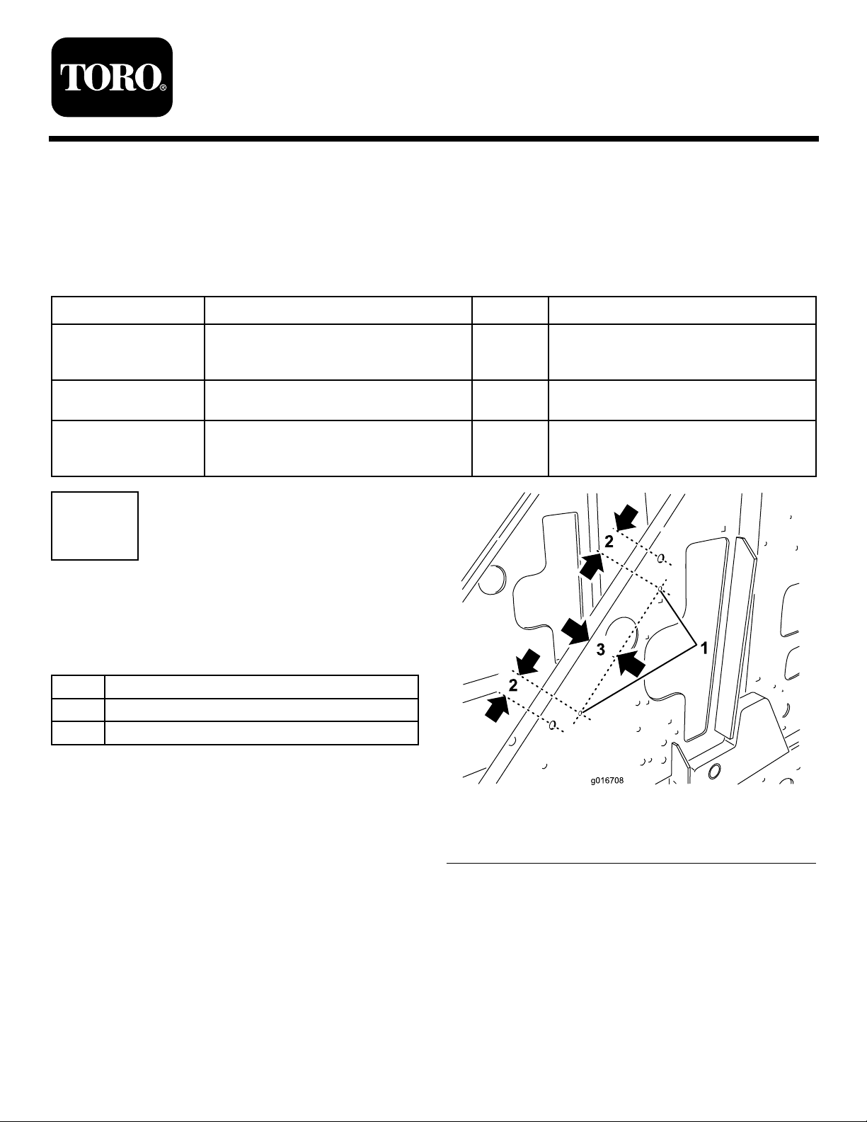
2.Locateanddrill4holesintheframeinthelocations
illustratedinFigure1andFigure2.Youmayusea
#2(0.221inch),5.5mm,5.6mm,or5.7mmdrill
bittodrilltheholes.
©2011—TheT oro®Company
8111LyndaleAvenueSouth
Bloomington,MN55420
Registeratwww.Toro.com.
1.Drillhere
2.1.36inch(3.45cm)
Figure1
3.2.81inches(7.14cm)
OriginalInstructions(EN)
PrintedintheUSA.
AllRightsReserved
Page 2
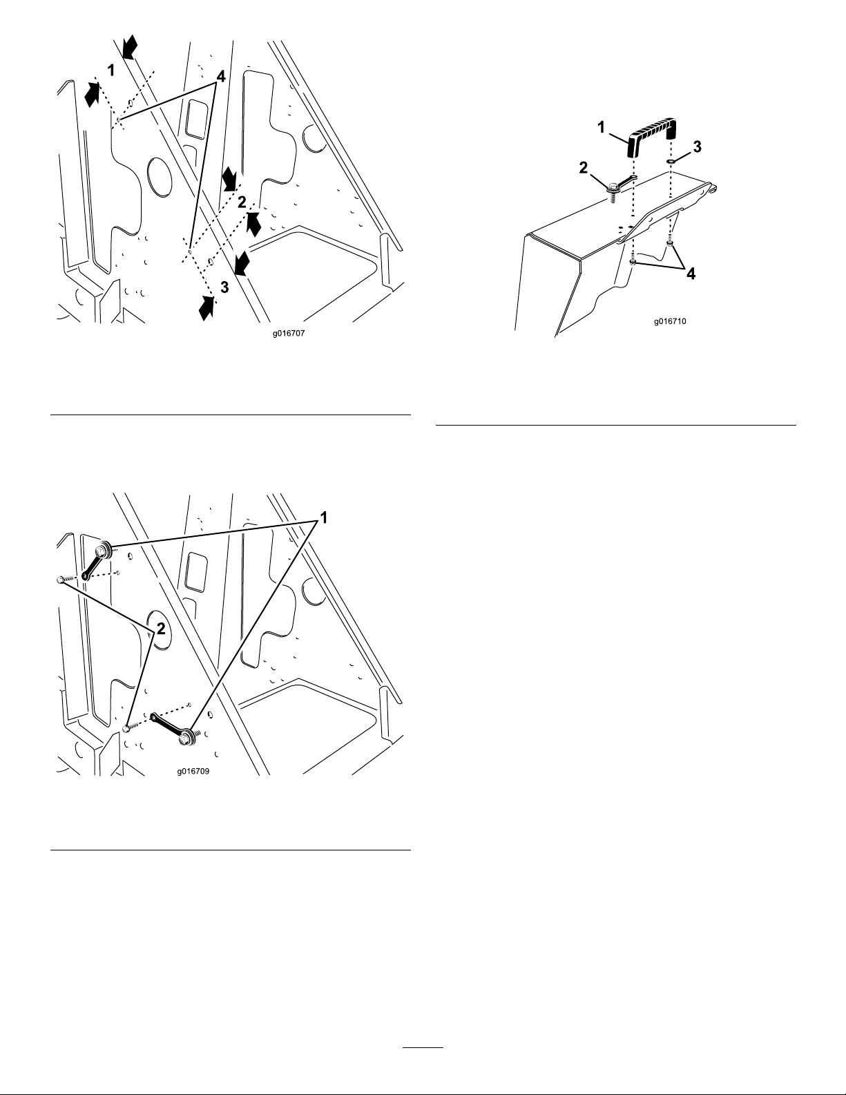
7.Installtherearaccesscoverhandlewithawasher
ontheleftsideandalanyardfastenerassemblyon
theotherandsecureitwiththefastenersremoved
previously(
Figure4).
Figure2
1.3.44inches(8.74cm)3.2.81inches(7.14cm)
2.1.36inch(3.45cm)
4.Drillhere
3.Installthe4lanyardfastenerassembliesintothe
holesyoudrilledusing4self-tappingscrews(1/4x
1/2inch)(Figure3).
Figure4
1.Rearaccesscoverhandle3.Washer
2.Lanyardfastener
4.Fastenersremoved
previously
Figure3
1.Lanyardfastener2.Self-tappingscrew(1/4x
1/2inch)
4.Installthehoodandsecureitusingthefourlanyard
fasteners.
5.Removeanddiscardtheboltsecuringtherearaccess
cover,andopenthecover.
6.Removetherearaccesscoverhandle,savingthe
fasteners.
2
Page 3

2
3
SettingtheEngineSpeed
Partsneededforthisprocedure:
1Aluminumtube
Procedure
1.Starttheengineandletitrunforafewminutes.
2.Usingatachometerandthethrottleadjustment
screwontheengine(Figure5),settheenginespeed
to3200RPMmaximum,thentightenthejamnuton
theadjustingscrew .
ApplyingDecals
Partsneededforthisprocedure:
2Decal105-8428
1Decal117-1761
1Decal98-4387
Procedure
1.PeelofftheWheelMasterdecalslocatedonthesides
oftheloaderarmsandapplydecal105-8428intheir
placeoneachside.
2.Applydecal98-4387and117-1761inthelocations
shownin
Figure6.
Figure5
1.Throttleadjustmentscrew2.Aluminumtube
3.Stoptheengine.
4.Slideanaluminumtubeoverthethrottleadjustment
screwandjamnut(
thescrewsothatthescrewcannotbeadjustedagain.
5.Closetherearaccesscoverandsecureitwiththe
lanyardfastener.
Figure5)andcrimpitdownover
Figure6
1.Decal98-43872.Decal117-1761
3
Page 4

 Loading...