

Page 1
FormNo.3420-641RevA
TX525CompactToolCarrier
ModelNo.22323—SerialNo.401800000andUp
ModelNo.22323G—SerialNo.401800000andUp
ModelNo.22324—SerialNo.401800000andUp
Registeratwww.T oro.com.
OriginalInstructions(EN)
*3420-641*A
Page 2
ThisproductcomplieswithallrelevantEuropean
directives;fordetails,pleaseseetheseparateproduct
specicDeclarationofConformity(DOC)sheet.
WARNING
CALIFORNIA
Proposition65Warning
Thisproductcontainsachemical
orchemicalsknowntotheStateof
Californiatocausecancer,birthdefects,
orreproductiveharm.
Theengineexhaustfromthisproduct
containschemicalsknowntotheStateof
Californiatocausecancer,birthdefects,
orotherreproductiveharm.
DANGER
Theremaybeburiedutilitylinesinthework
area.Diggingintothemmaycauseashock
oranexplosion.
Havethepropertyorworkareamarkedfor
buriedlinesanddonotdiginmarkedareas.
Contactyourlocalmarkingserviceorutility
companytohavethepropertymarked(for
example,intheUS,call811orinAustralia,
call1100forthenationwidemarkingservice).
Introduction
Thismachineisacompacttoolcarrierintendedfor
useinvariousearthandmaterialsmovingactivitiesfor
landscapingandconstructionwork.Itisdesignedto
operateawidevarietyofattachmentseachofwhich
performaspecializedfunction.
Readthisinformationcarefullytolearnhowtooperate
andmaintainyourproductproperlyandtoavoid
injuryandproductdamage.Youareresponsiblefor
operatingtheproductproperlyandsafely .
YoumaycontactTorodirectlyatwww.Toro.com
forproductsafetyandoperationtrainingmaterials,
accessoryinformation,helpndingadealer,orto
registeryourproduct.
Wheneveryouneedservice,genuineToroparts,or
additionalinformation,contactanAuthorizedService
DealerorToroCustomerServiceandhavethemodel
andserialnumbersofyourproductready.Figure1
identiesthelocationofthemodelandserialnumbers
ontheproduct.Writethenumbersinthespace
provided.
Important:Withyourmobiledevice,youcan
scantheQRcodeontheserialnumberdecal(if
equipped)toaccesswarranty,parts,andother
productinformation.
ItisaviolationofCaliforniaPublicResourceCode
Section4442or4443touseoroperatetheengineon
anyforest-covered,brush-covered,orgrass-covered
landunlesstheengineisequippedwithaspark
arrester,asdenedinSection4442,maintainedin
effectiveworkingorderortheengineisconstructed,
equipped,andmaintainedforthepreventionofre.
Theenclosedengineowner'smanualissupplied
forinformationregardingtheUSEnvironmental
ProtectionAgency(EPA)andtheCaliforniaEmission
ControlRegulationofemissionsystems,maintenance,
andwarranty.Replacementsmaybeorderedthrough
theenginemanufacturer.
g243442
Figure1
1.Modelandserialnumberlocation
ModelNo.
SerialNo.
Thismanualidentiespotentialhazardsandhas
safetymessagesidentiedbythesafety-alertsymbol
(Figure2),whichsignalsahazardthatmaycause
©2018—TheToro®Company
8111LyndaleAvenueSouth
Bloomington,MN55420
Contactusatwww.Toro.com.
2
PrintedintheUSA
AllRightsReserved
Page 3

seriousinjuryordeathifyoudonotfollowthe
recommendedprecautions.
Figure2
1.Safety-alertsymbol
Thismanualuses2wordstohighlightinformation.
Importantcallsattentiontospecialmechanical
informationandNoteemphasizesgeneralinformation
worthyofspecialattention.
Contents
Safety.......................................................................4
GeneralSafety...................................................4
SafetyandInstructionalDecals..........................5
ProductOverview.....................................................9
Controls.............................................................9
Specications..................................................13
Attachments/Accessories.................................13
BeforeOperation.................................................13
BeforeOperationSafety...................................13
AddingFuel......................................................14
PerformingDailyMaintenance..........................14
DuringOperation.................................................15
DuringOperationSafety...................................15
StartingtheEngine...........................................16
DrivingtheMachine..........................................16
ShuttingOfftheEngine.....................................16
UsingAttachments...........................................17
AfterOperation....................................................18
AfterOperationSafety......................................18
MovingaNon-FunctioningMachine..................18
TransportingtheMachine.................................19
LiftingtheMachine...........................................20
Maintenance...........................................................21
RecommendedMaintenanceSchedule(s)...........21
Pre-MaintenanceProcedures..............................22
MaintenanceSafety..........................................22
UsingtheCylinderLock....................................22
AccessingInternalComponents.......................23
Lubrication..........................................................25
GreasingtheMachine.......................................25
EngineMaintenance...........................................25
EngineSafety...................................................25
ServicingtheAirCleaner..................................25
ServicingtheEngineOil....................................26
FuelSystemMaintenance...................................28
CheckingtheFuelLinesand
Connections..................................................28
DrainingtheFuelFilter/WaterSeparator...........28
ReplacingtheFuelFilterCanisterand
In-LineFilter..................................................29
BleedingtheFuelSystem.................................29
DrainingtheFuelT ank(s)..................................30
ElectricalSystemMaintenance...........................30
ElectricalSystemSafety...................................30
ServicingtheBattery.........................................31
g000502
ServicingtheFuses..........................................33
DriveSystemMaintenance..................................34
ServicingtheTracks.........................................34
CoolingSystemMaintenance..............................37
CoolingSystemSafety.....................................37
ServicingtheCoolingSystem...........................37
BrakeMaintenance.............................................39
TestingtheParkingBrake.................................39
BeltMaintenance................................................39
CheckingtheConditionoftheHydraulic
PumpBelt.....................................................39
ControlsSystemMaintenance.............................40
AdjustingtheControls.......................................40
HydraulicSystemMaintenance...........................42
HydraulicSystemSafety...................................42
HydraulicFluidSpecications...........................42
CheckingtheHydraulic-FluidLevel...................42
ReplacingtheHydraulicFilter...........................43
ChangingtheHydraulicFluid............................44
Cleaning..............................................................45
RemovingDebris..............................................45
CleaningtheChassis........................................45
Storage...................................................................45
StorageSafety..................................................45
Storage.............................................................45
Troubleshooting......................................................46
Schematics.............................................................50
3
Page 4

Safety
GeneralSafety
Alwaysfollowallsafetyinstructionstoavoidserious
injuryordeath.Usingthisproductforpurposesother
thanitsintendedusecouldprovedangeroustoyou
andbystanders.
•Donotcarryaloadwiththearmsraised;always
carryloadsclosetotheground.
•Slopesareamajorfactorrelatedtoloss-of-control
andtip-overaccidents,whichcanresultinsevere
injuryordeath.Operatingthemachineonany
slopeoruneventerrainrequiresextracaution.
•Operatethemachineupanddownslopeswith
theheavyendofthemachineuphillandtheload
closetotheground.Weightdistributionchanges
withattachments.Anemptybucketmakesthe
rearofthemachinetheheavyend,andafull
bucketmakesthefrontofthemachinetheheavy
end.Mostotherattachmentsmakethefrontofthe
machinetheheavyend.
•Havethepropertyorworkareamarkedforburied
linesandotherobjects,anddonotdiginmarked
areas.
•ReadandunderstandthecontentofthisOperator’s
Manualbeforestartingtheengine.
•Useyourfullattentionwhileoperatingthe
machine.Donotengageinanyactivitythat
causesdistractions;otherwise,injuryorproperty
damagemayoccur.
•Neverallowchildrenoruntrainedpeopleto
operatethemachine.
•Keepyourhandsandfeetawayfromthemoving
componentsandattachments.
•Donotoperatethemachinewithouttheguards
andothersafetyprotectivedevicesinplaceand
workingonthemachine.
•Keepbystandersandpetsasafedistanceaway
fromthemachine.
•Stopthemachine,shutofftheengine,andremove
thekeybeforeservicing,fueling,orunclogging
themachine.
Improperlyusingormaintainingthismachinecan
resultininjury.Toreducethepotentialforinjury,
complywiththesesafetyinstructionsandalwayspay
attentiontothesafety-alertsymbol,whichmeans
Caution,Warning,orDanger—personalsafety
instruction.Failuretocomplywiththeseinstructions
mayresultinpersonalinjuryordeath.
Youcanndadditionalsafetyinformationwhere
neededthroughoutthismanual.
4
Page 5
SafetyandInstructionalDecals
Safetydecalsandinstructionsareeasilyvisibletotheoperatorandarelocatednearanyarea
ofpotentialdanger.Replaceanydecalthatisdamagedormissing.
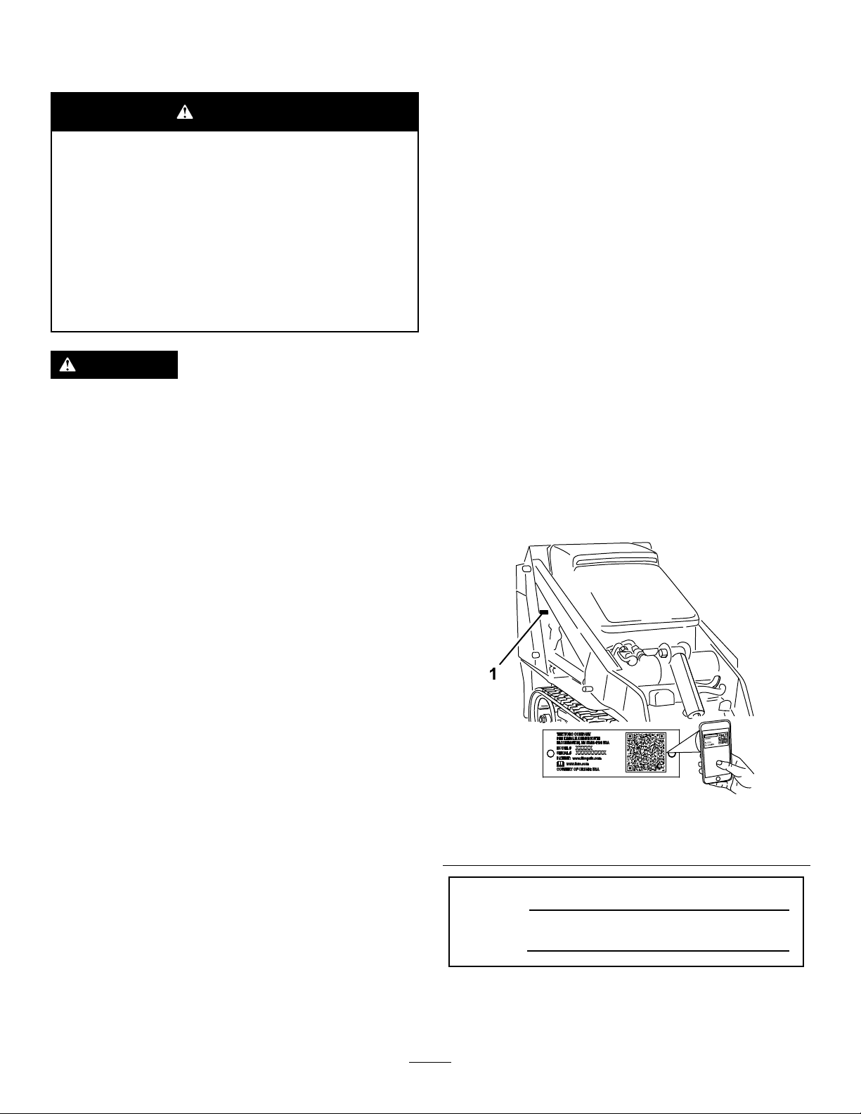
decal93-7814
93-7814
BatterySymbols
Someorallofthesesymbolsareonyourbattery .
1.Explosionhazard
2.Nore,opename,or
smoking
3.Causticliquid/chemical
burnhazard
4.Weareyeprotection.9.Flusheyesimmediately
5.ReadtheOperator's
Manual.
6.Keepbystandersasafe
distancefromthebattery.
7.Weareyeprotection;
explosivegasescan
causeblindnessandother
injuries.
8.Batteryacidcancause
blindnessorsevereburns.
withwaterandgetmedical
helpfast.
10.Containslead;donot
discard
93-6680
decalbatterysymbols
1.Entanglementhazard,belt—stayawayfrommovingparts.
decal93-9084
93-9084
1.Liftpoint/Tie-downpoint
decal93-6680
93-6681
1.Cutting/dismembermenthazard,fan—stayawayfrom
movingparts.
93-6686
1.Hydraulicuid
2.ReadtheOperator'sManual.
decal100-4650
100-4650
1.Crushinghazardofhand—keepbystandersasafedistance
decal93-6681
awayfromthemachine.
2.Crushinghazardoffoot—keepbystandersasafedistance
awayfromthemachine.
decal100-8821
decal93-6686
100-8821
1.Crushinghazardandcuttinghazardofhand—stayasafe
distanceawayfromthefrontofthetractionunitwhenthe
loaderarmsareraised.
5
Page 6
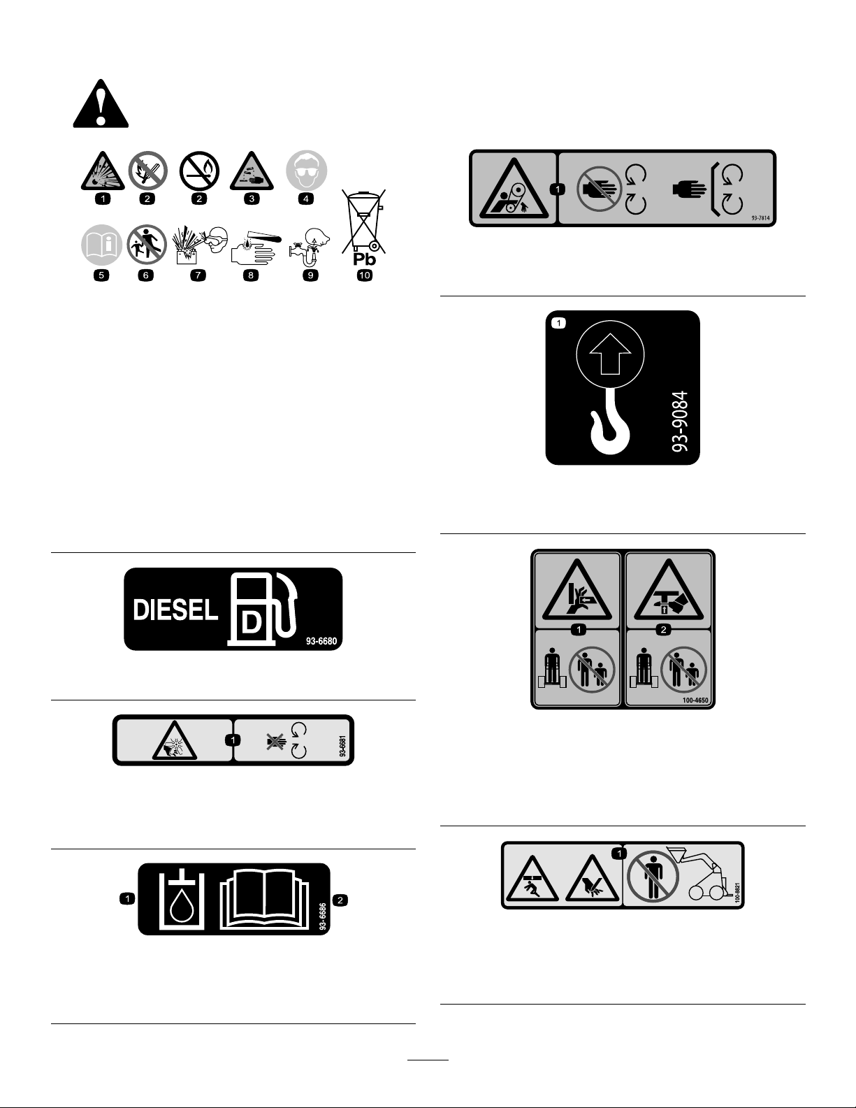
1.Warning—donotcarrypassengers.
decal100-8822
100-8822
decal115-4857
115-4857
106-6755
1.Enginecoolantunder
pressure.
2.Explosionhazard—read
theOperator'sManual.
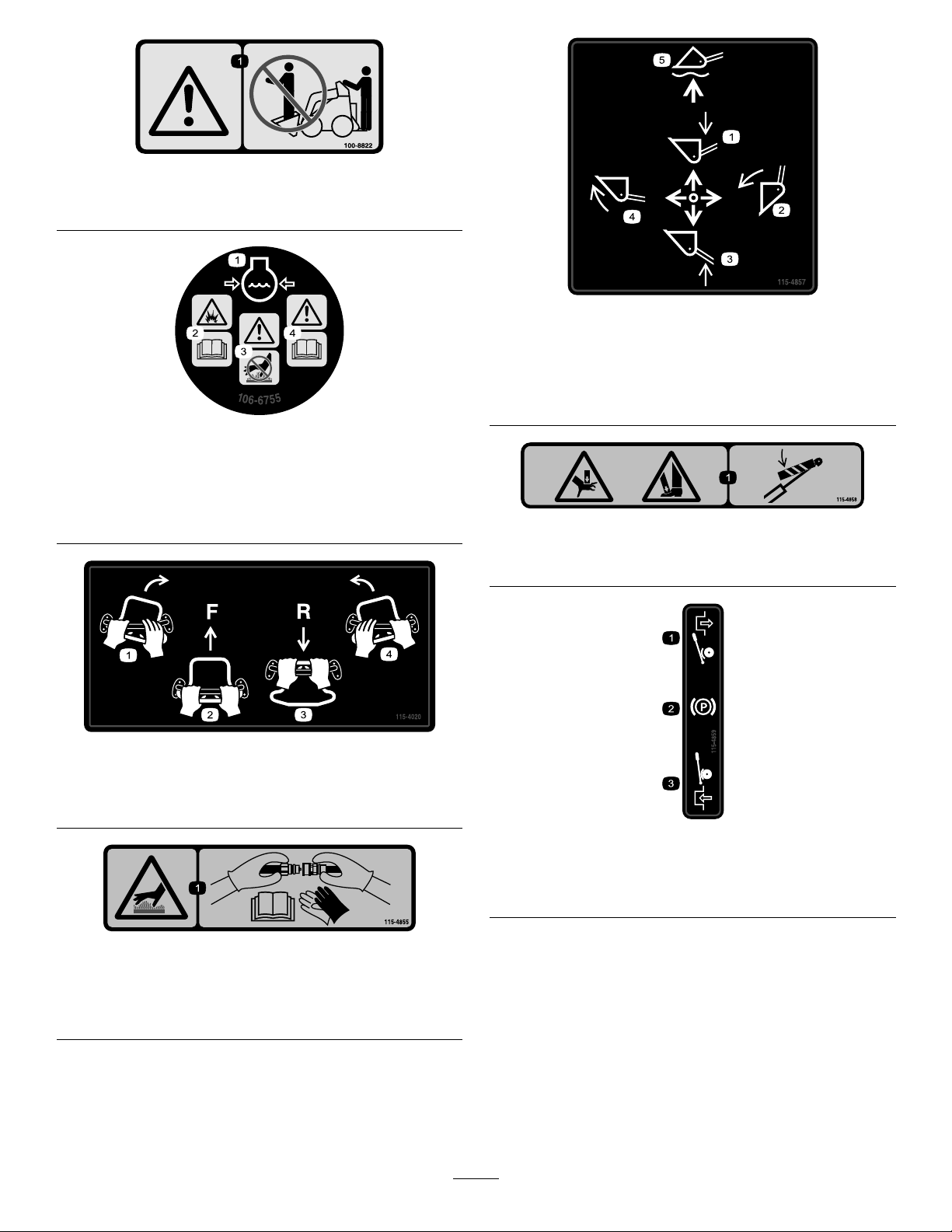
115-4020
1.Turnright3.Reverse
2.Forward
3.Warning—donottouchthe
hotsurface.
4.Warning—readthe
Operator'sManual.
4.Turnleft
1.Lowertheloaderarms.
4.Curlthebucket.
2.Dumpthebucket.5.Floatthebucketonthe
ground.
3.Raisetheloaderarms.
decal106-6755
decal115-4858
115-4858
1.Crushinghazardofhandsorfeet—installthecylinderlock.
decal115-4020
decal115-4859
115-4859
115-4855
1.Hotsurface/burnhazard—wearprotectivegloveswhen
handlingthehydrauliccouplersandreadtheOperator's
Manualforinformationonhandlinghydrauliccomponents.
1.Disengaged3.Engaged
2.Parkingbrake
decal115-4855
6
Page 7
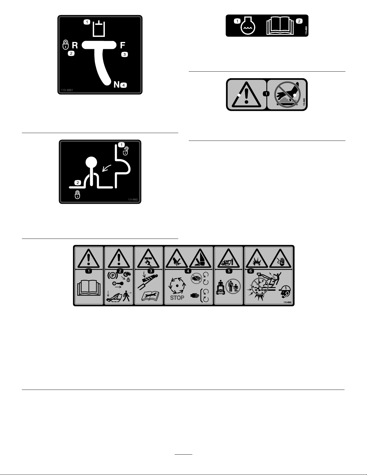
decal115-4865
115-4865
115-4861
1.Auxiliaryhydraulics3.Forward
2.Lockedreverse(detent)4.Neutral(off)
115-4862
1.Loader-valve
lock—unlocked
2.Loader-valvelock—locked
1.Enginecoolant
2.ReadtheOperator's
Manual.
decal115-4861
decal115-4882
115-4882
1.Warning—stayasafedistanceawayfromthehotsurfaces.
decal115-4862
115-4860
1.Warning—readtheOperator'sManual.
2.Warning—settheparkingbrake,shutofftheengine,removetheignitionkeyandlowertheloaderarmsbeforeleavingthemachine.
3.Crushinghazard—installthecylinderlockandreadtheinstructionsbeforeservicingorperformingmaintenance.
4.Cuttinghazardofhandsorfeet—waitforallmovingpartstostop;stayawayfrommovingparts;keepallguardsandshieldsin
place.
5.Crushing/dismembermenthazardofbystanders—keepbystandersasafedistanceawayfromthemachine.
6.Explosionandelectricshockhazard—donotdiginareaswithburiedgasorelectricallines;contactlocalpowerorganizations
beforedigging.
7
decal115-4860
Page 8
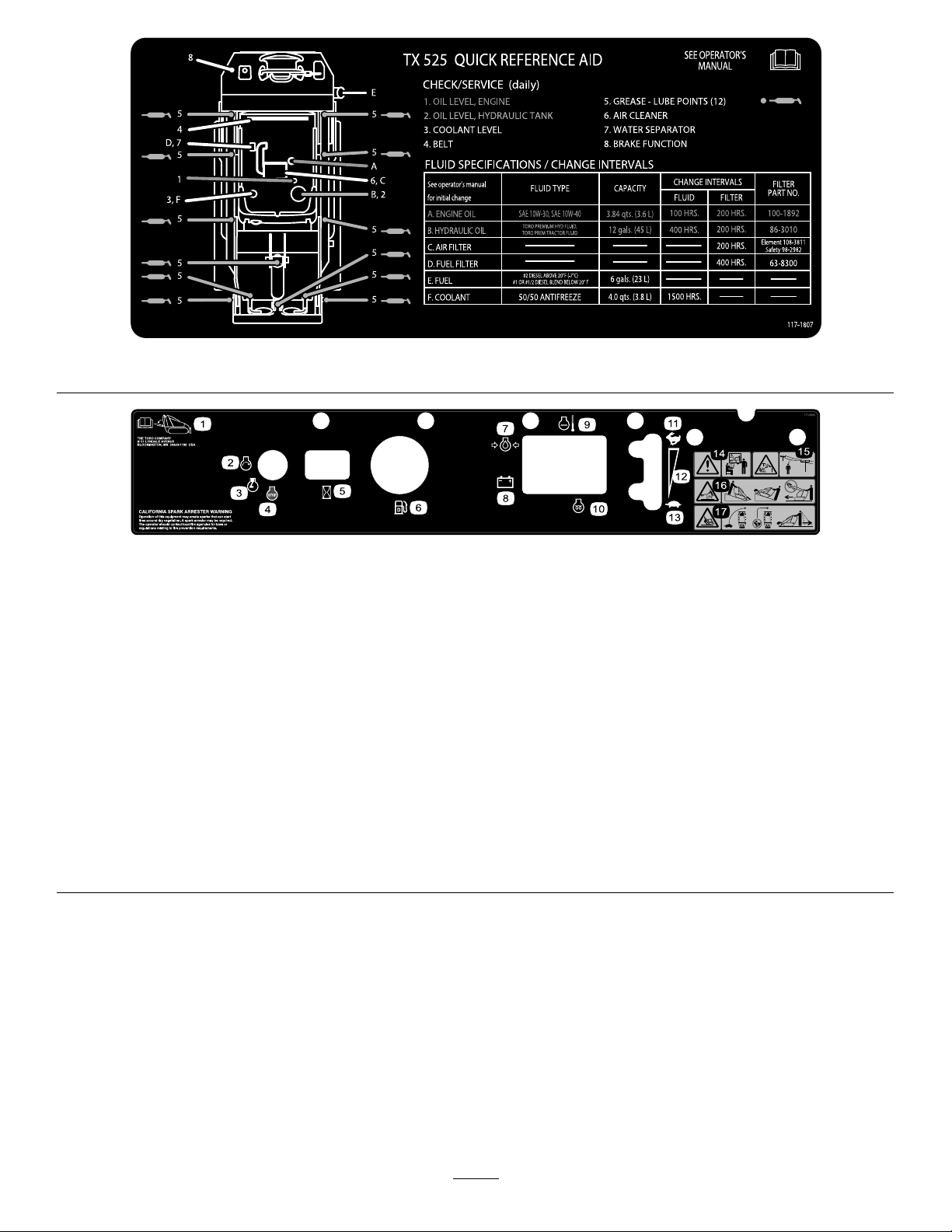
decal117-1807
117-1807
decal117-9905
117-9905
1.Operator'sManuallocation
2.Engine—start7.Engineoilpressure
3.Engine—run8.Battery
6.Fuelgauge—diesel1 1.Fast16.Tippinghazard—movethe
12.Continuousvariablesetting
13.Slow
4.Engine—stop9.Enginetemperature14.Warning—donotoperate
thismachineunlessyou
aretrained.
5.Hourmeter
10.Glowplug
15.Electricshockhazard,
overheadpowerlines—stay
awayfromoverheadpower
lines.
tractionunitwiththeheavy
enduphill;carryloadslow;
neverjerkthecontrols;use
asteady,evenmotion.
17.Tippinghazard—slowthe
tractionunitwhenturning,
donottravelfastwhen
turning,lookbehindand
downwhenreversing.
8
Page 9
ProductOverview
Controls
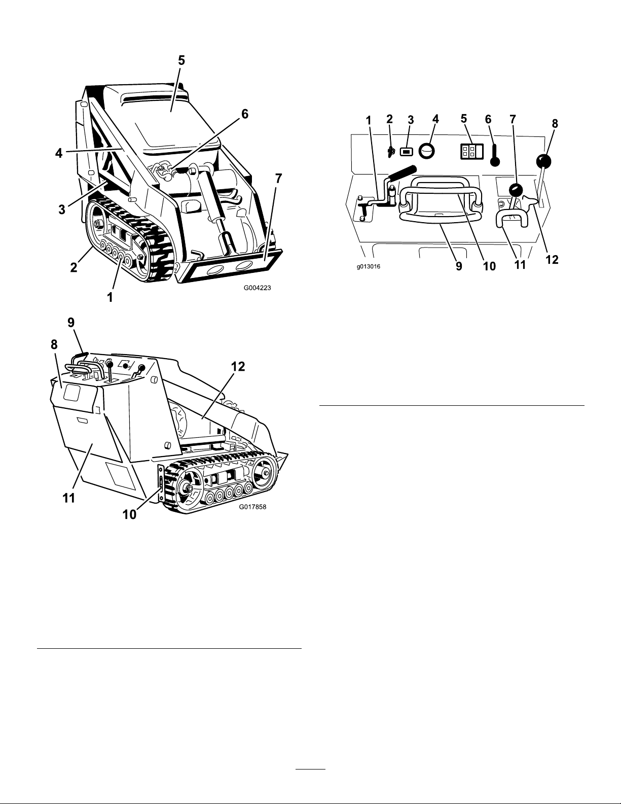
Becomefamiliarwithallthecontrols(Figure4)before
youstarttheengineandoperatethetractionunit.
ControlPanel
g013016
Figure4
Figure3
1.Roadwheels7.Mountplate
2.Track
3.Liftcylinder9.Controlpanel
4.Loaderarms
5.Hood11.Rear-accesscover
6.Auxiliaryhydraulic
couplers
8.Reverse-safetyplate
10.Tie-down/liftloop
12.Sidepanelscreen
g004223
1.Auxiliaryhydraulicslever
2.Keyswitch8.Parking-brakelever
3.Hourmeter9.Tractioncontrol
4.Fuelgauge
5.Indicatorlightsand
glow-plugswitch
6.Throttlelever12.Loader-valvelock
7.Loader-arm/attachment-tilt
lever
10.Referencebar
11.Loader-control-reference
bar
KeySwitch
Thekeyswitch,usedtostartandshutofftheengine,
has3positions:OFF,RUN,andST ART.Referto
StartingtheEngine(page16).
g017858
ThrottleLever
Movethecontrolforwardtoincreasetheenginespeed
andrearwardtodecreasespeed.
ReferenceBar
Whendrivingthetractionunit,usethereferencebar
asahandleandaleveragepointforcontrollingthe
tractioncontrolandtheauxiliary-hydraulicslever.T o
ensuresmooth,controlledoperation,donottake
bothhandsoffthereferencebarwhileoperatingthe
machine.
9
Page 10
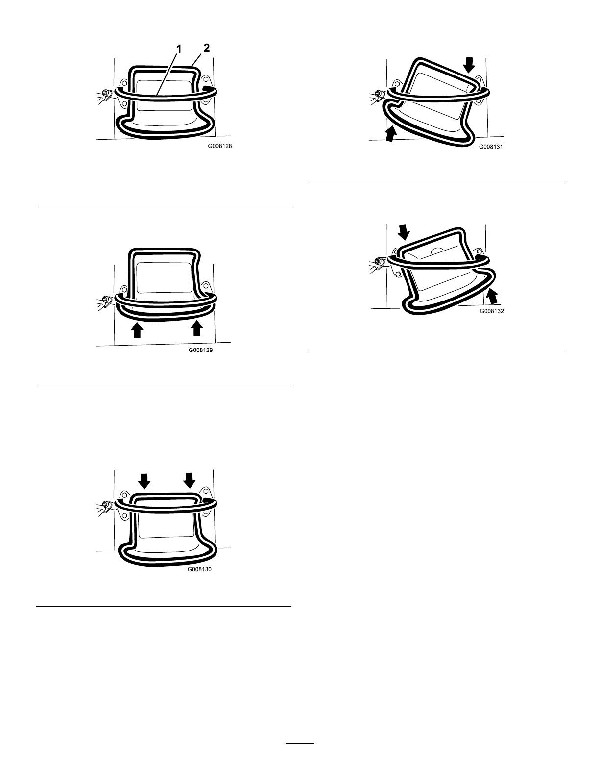
TractionControl
•Toturnright,rotatethetractioncontrolclockwise
(Figure8).
Figure5
1.Referencebar
2.Tractioncontrol
•Tomoveforward,movethetractioncontrolforward
(Figure6).
Figure6
•Tomoverearward,movethetractioncontrol
rearward(Figure7).
Important:Whenreversing,lookbehindyou
forobstructionsandkeepyourhandsonthe
referencebar.
g008128
Figure8
g008131
•Toturnleft,rotatethetractioncontrol
counterclockwise(Figure9).
g008132
Figure9
g008129
•Tostopthemachine,releasethetractioncontrol
(Figure5).
Note:Thefartheryoumovethetractioncontrolin
anydirection,thefasterthemachinemovesinthat
direction.
Figure7
g008130
10
Page 11
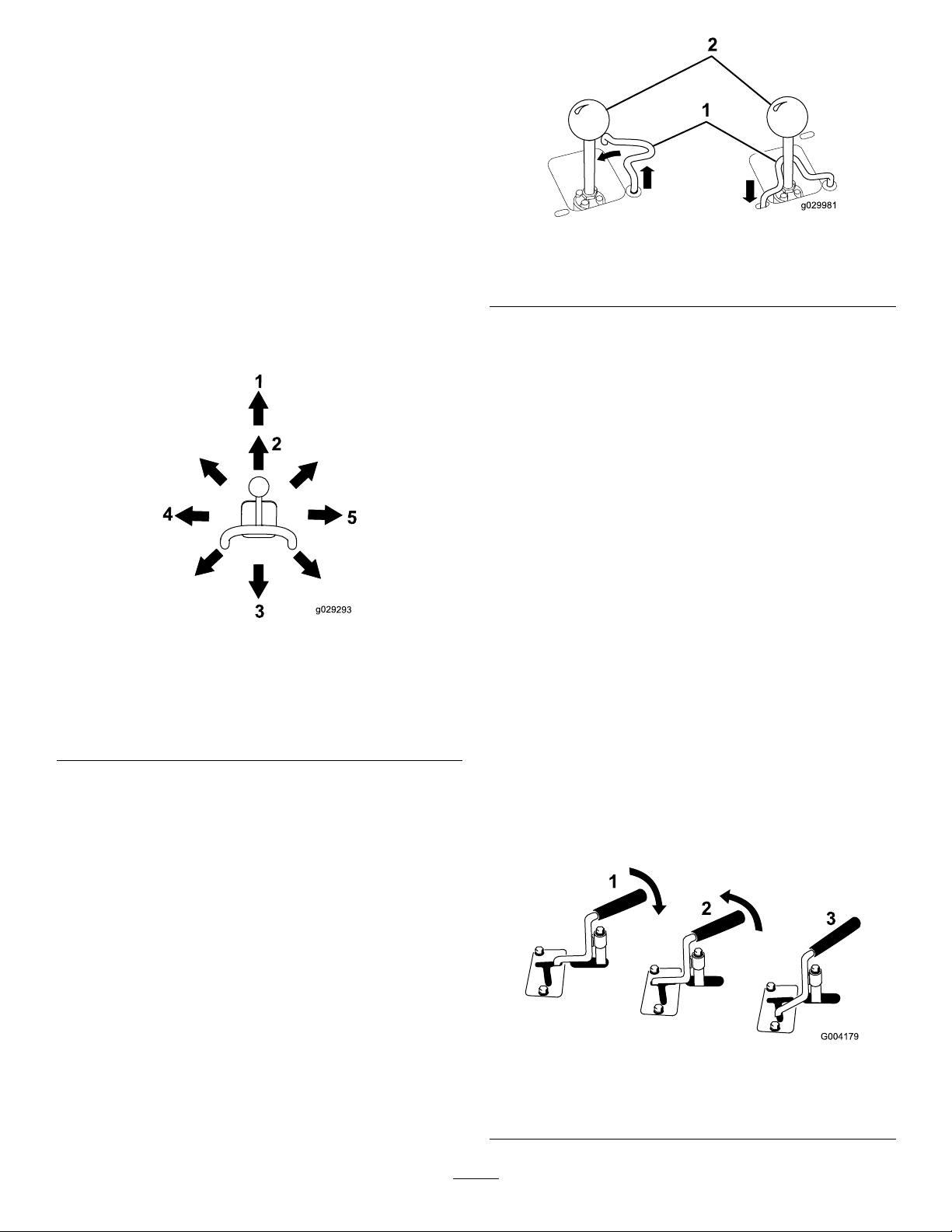
LoaderArm/Attachment-TiltLever
•Totilttheattachmentforward,slowlymovethe
levertotheright(Figure10).
•Totilttheattachmentrearward,slowlymovethe
levertotheleft(Figure10).
•Tolowertheloaderarms,slowlymovethelever
forward(Figure10).
•Toraisetheloaderarms,slowlymovethelever
rearward(Figure10).
•Tolowertheloaderarmstoadetent(oat)
position,pushtheleverfullyforward(Figure10).
Note:Thisallowsattachmentssuchastheleveler
andthehydraulicbladetofollowthecontoursof
theground(i.e.,oat)whengrading.
Figure10
1.Detent(oat)position
2.Lowertheloaderarms.5.Tilttheattachment
3.Raisetheloaderarms.
4.Tilttheattachment
rearward.
forward.
g029981
Figure11
1.Loaderarm/attachment-tilt
lever
2.Loader-valvelock
Loader-Control-ReferenceBar
Theloader-control-referencebarhelpsstabilizeyour
handwhileoperatingtheloaderarm/attachment-tilt
lever(Figure3).
HourMeter
Thehourmeterdisplaysthenumberofhoursof
operationthathavebeenloggedonthemachine.
Auxiliary-HydraulicsLever
•Tooperateahydraulicattachmentintheforward
g029293
direction,rotatetheauxiliary-hydraulicslever
rearwardandpullitdowntothereferencebar
(Figure12,number1).
•Tooperateahydraulicattachmentinthereverse
direction,rotatetheauxiliary-hydraulicslever
rearward,thenmoveitleftintotheupperslot
(Figure12,number2).
Bymovingthelevertoanintermediateposition(e.g.,
forwardandleft),youcanmovetheloaderarmsand
tilttheattachmentatthesametime.
Loader-ValveLock
Theloader-valvelocksecurestheloader
arm/attachment-tiltleversothatyoucannotpushit
forward.Thishelpstoensurethatnooneaccidentally
lowerstheloaderarmsduringmaintenance.Secure
theloaderarmswiththelockanytimeyouneedto
shutoffthemachinewiththeloaderarmsraised.
Tosetthelock,liftuponitsothatitclearstheholein
thecontrolpanelandswingittotheleft,infrontof
theloader-armlever,pushingitdownintothelocked
position(Figure11).
Note:IfyoureleasetheleverwhileintheFORWARD
position,theleverautomaticallyreturnstothe
NEUTRALposition(Figure12,number3).Ifitisinthe
REVERSEposition,itremainsthereuntilyoupullitout
oftheslot.
Figure12
1.Forward-owhydraulics
2.Reverse-owhydraulics
11
3.Neutral
g004179
Page 12
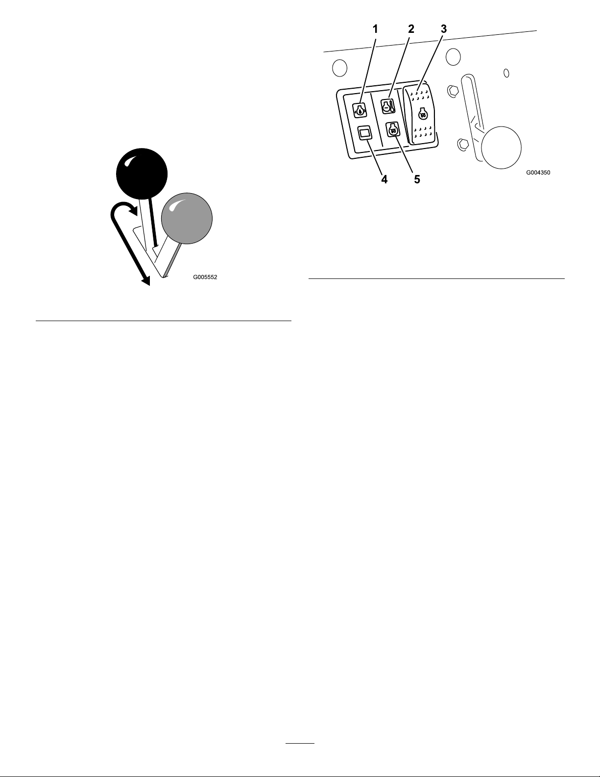
Parking-BrakeLever
•Toengagetheparkingbrake,pushthelever
forwardandtotheleftandthenpullitrearward
(Figure13).
Note:Thetractionunitmayrollslightlybeforethe
brakesengageinthedrivesprocket.
•Toreleasethebrake,pushtheleverforwardand
thenright,intothenotch(Figure13).
g004350
Figure14
Figure13
FuelGauge
Thisgaugemeasurestheamountoffuelinthefuel
tank(s).
Engine-OilPressureLight
Iftheengine-oilpressuregetstoolow,thislight
illuminatesandanaudiblealarmsounds.Ifthis
happens,shutofftheengineimmediatelyandcheck
theoillevel.Ifitislow,addoilandlookforpossible
leaks.
1.Engine-oilpressurelight4.Battery-chargeindicator
2.Engine-coolant
temperaturelight
3.Glow-plugswitch
g005552
light
5.Glow-pluglight
Battery-ChargeIndicatorLight
Ifthebatterychargebecomestoolow,thislight
illuminatesandanaudiblealarmsounds.Ifthis
happens,shutofftheengineandchargeorreplace
thebattery.Checkthetensionofthealternatorbelt;
refertoyourengineowner’smanual.
Engine-CoolantTemperatureLight
Iftheenginecoolantgetstoohot,thislightilluminates
andanaudiblealarmsounds.Ifthishappens,shutoff
theengineandallowthetractionunittocool.Check
thecoolantlevelwhentheenginehasfullycooled.
Glow-PlugLight
Thislightilluminateswhiletheglowplugsarecharged
andwarmingtheengine.
Glow-PlugSwitch
Pressandholdthisswitchfor10secondstoactivate
theglowplugsbeforestartingtheengine.
12
Page 13

Specications
Note:Specicationsanddesignaresubjectto
changewithoutnotice.
Model22323
Width
Length
Height
Weight
Operatingcapacity(withstandard
bucket)
Tippingcapacity(withstandardbucket)717kg(1,580lb)
Wheelbase
Dumpheight(withnarrowbucket)119cm(47inches)
Reach—fullyraised(withnarrowbucket)55cm(22inches)
Heighttohingepin(narrowbucketin
highestposition)
Model22324
Width
Length
Height
Weight
Operatingcapacity(withstandard
bucket)
Tippingcapacity(withstandardbucket)717kg(1,580lb)
Wheelbase
Dumpheight(withnarrowbucket)119cm(47inches)
Reach—fullyraised(withnarrowbucket)55cm(22inches)
Heighttohingepin(narrowbucketin
highestposition)
Attachments/Accessories
AselectionofToroapprovedattachmentsand
accessoriesisavailableforusewiththemachineto
enhanceandexpanditscapabilities.Contactyour
AuthorizedServiceDealerorDistributororgoto
www.T oro.comforalistofallapprovedattachments
andaccessories.
Important:UseonlyToroapprovedattachments.
Otherattachmentsmaycreateanunsafeoperating
environmentordamagethetractionunit.
Toensureoptimumperformanceandcontinuedsafety
certicationofthemachine,useonlygenuineT oro
replacementpartsandaccessories.Replacement
partsandaccessoriesmadebyothermanufacturers
couldbedangerous,andsuchusecouldvoidthe
productwarranty.
86cm(34inches)
180cm(71inches)
117cm(46inches)
864kg(1,904lb)
251kg(553lb)
79cm(31inches)
168cm(66inches)
104cm(41inches)
180cm(71inches)
109cm(43inches)
913kg(2,013lb)
251kg(553lb)
79cm(31inches)
168cm(66inches)
Operation
Note:Determinetheleftandrightsidesofthe
machinefromthenormaloperatingposition.
BeforeOperation
BeforeOperationSafety
GeneralSafety
•Neverallowchildrenoruntrainedpeopleto
operateorservicethemachine.Localregulations
mayrestricttheageorrequirecertiedtrainingof
theoperator.Theownerisresponsiblefortraining
alloperatorsandmechanics.
•Becomefamiliarwiththesafeoperationofthe
equipment,operatorcontrols,andsafetydecals.
•Knowhowtostopthemachineandshutoffthe
enginequickly.
•Checkthattheoperator'spresencecontrols,safety
switches,andshieldsareattachedandfunctioning
properly.Donotoperatethemachineunlessthey
arefunctioningproperly.
•Locatethepinch-pointareasmarkedonthe
machineandattachments;keepyourhandsand
feetawayfromtheseareas.
•Beforeoperatingthemachinewithanattachment,
ensurethattheattachmentisproperlyinstalled
andthatitisagenuineT oroattachment.Readall
theattachmentmanuals.
•Evaluatetheterraintodeterminewhataccessories
andattachmentsyouneedtoproperlyandsafely
performthejob.
•Havethepropertyorworkareamarkedforburied
linesandotherobjects,anddonotdiginmarked
areas;notethelocationofunmarkedobjectsand
structures,suchasundergroundstoragetanks,
wells,andsepticsystems.
•Inspecttheareawhereyouwillusetheequipment
andremovealldebris.
•Ensurethattheareaisclearofbystandersbefore
operatingthemachine.Stopthemachineif
anyoneentersthearea.
FuelSafety
•Useextracarewhenhandlingfuel.Itisammable
anditsvaporsareexplosive.
•Extinguishallcigarettes,cigars,pipes,andother
sourcesofignition.
•Useonlyanapprovedfuelcontainer.
•Donotremovethefuelcaporllthefueltank
whiletheengineisrunningorhot.
13
Page 14
•Donotaddordrainfuelinanenclosedspace.
•Donotstorethemachineorfuelcontainerwhere
thereisanopename,spark,orpilotlight,such
asonawaterheaterorotherappliance.
•Ifyouspillfuel,donotattempttostarttheengine;
avoidcreatinganysourceofignitionuntilthefuel
vaporshavedissipated.
AddingFuel
RecommendedFuel
Useonlyclean,freshdieselfuelorbiodieselfuelswith
low(<500ppm)orultralow(<15ppm)sulfurcontent.
Theminimumcetaneratingshouldbe40.Purchase
fuelinquantitiesthatyoucanusewithin180daysto
ensurefuelfreshness.
Usesummer-gradedieselfuel(No.2-D)at
temperaturesabove-7°C(20°F)andwintergrade
(No.1-DorNo.1-D/2-Dblend)belowthat
temperature.Usingwinter-gradefuelatlower
temperaturesprovideslowerashpointandcoldow
characteristics,whicheasesstartingandreducesfuel
lterplugging.
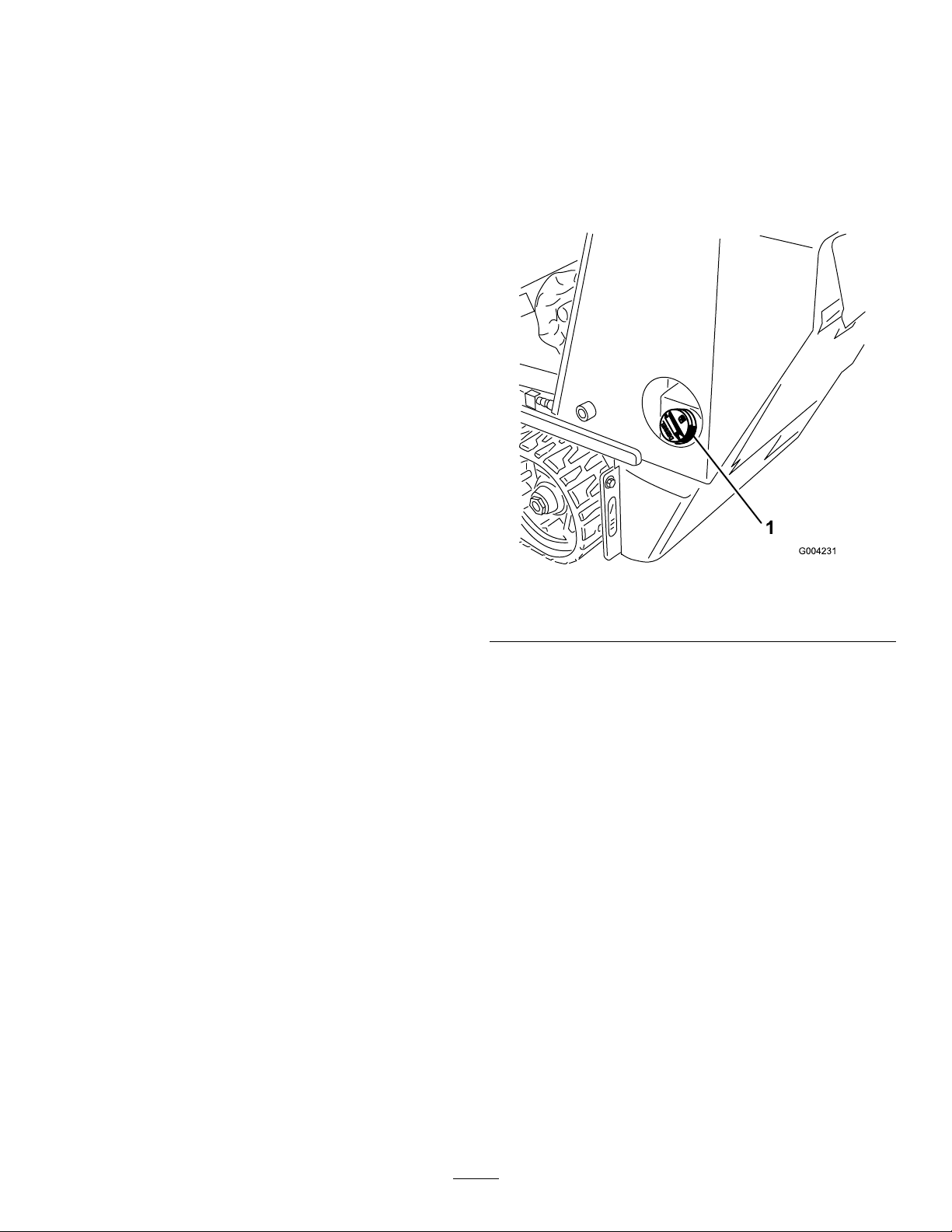
FillingtheFuelTank(s)
1.Parkthemachineonalevelsurface,engage
theparkingbrake(ifequipped),andlowerthe
loaderarms.
2.Shutofftheengine,removethekey,andallow
theenginetocool.
3.Cleanaroundthefuel-tankcapandremoveit
(Figure15).
Usingsummer-gradefuelabove-7°C(20°F)
contributestowardlongerfuelpumplifeandincreased
powercomparedtowinter-gradefuel.
Important:Donotusekeroseneorgasoline
insteadofdieselfuel.Failuretoobservethis
cautionwilldamagetheengine.
BiodieselReady
Thismachinecanalsouseabiodieselblendedfuel
ofuptoB20(20%biodiesel,80%petrodiesel).The
petrodieselportionshouldbeloworultralowsulfur.
Observethefollowingprecautions:
•Thebiodieselportionofthefuelmustmeet
specicationASTMD6751orEN14214.
•TheblendedfuelcompositionshouldmeetASTM
D975orEN590.
•Paintedsurfacesmaybedamagedbybiodiesel
blends.
•UseB5(biodieselcontentof5%)orlesserblends
incoldweather.
•Monitorseals,hoses,gasketsincontactwithfuel
astheymaydegradeovertime.
•Fuellterpluggingmayoccurforatimeafter
convertingtobiodieselblends.
•Contactyourdistributorformoreinformationon
biodiesel.
g004231
Figure15
1.Fuel-tankcap
4.Fillthetanktoabout2.5cm(1inch)belowthe
topofthetank,notthellerneck,withfuel.
Important:Thisspaceinthetankallows
fueltoexpand.Donotllthefueltank
completelyfull.
5.Installthefuel-tankcapsecurely,turningituntil
itclicks.
6.Wipeupanyspilledfuel.
PerformingDaily Maintenance
Beforestartingthemachineeachday ,performthe
EachUse/DailyprocedureslistedintheMaintenance
(page21).
Important:Checkthehydraulic-uidlevel
andbleedthefuelsystembeforestartingthe
engineforthersttime;refertoCheckingthe
Hydraulic-FluidLevel(page42)andBleedingthe
FuelSystem(page29).
14
Page 15

DuringOperation
DuringOperationSafety
GeneralSafety
•Donotcarryaloadwiththearmsraised.Always
carryloadsclosetotheground.
•Donotexceedtheratedoperatingcapacity,asthe
machinemaybecomeunstable,whichmayresult
inlossofcontrol.
•UseonlyToro-approvedattachmentsand
accessories.Attachmentscanchangethestability
andtheoperatingcharacteristicsofthemachine.
•Formachineswithaplatform:
–Donotstepofftheplatformwiththeloadraised.
–Ifyoulosecontrolofthemachine,stepoff
theplatformandawayfromthedirectionthe
machineismoving.
–Donottrytostabilizethemachinebyputting
yourfootontheground.
–Donotplaceyourfeetundertheplatform.
–Donotmovethemachineunlessyouare
standingwithbothfeetontheplatformand
yourhandsareholdingontothehandles.
•Useyourfullattentionwhileoperatingthe
machine.Donotengageinanyactivitythat
causesdistractions;otherwise,injuryorproperty
damagemayoccur.
•Lookbehindanddownbeforebackingupto
ensurethatthepathisclear.
•Neverjerkthecontrols;useasteadymotion.
•Theowner/usercanpreventandisresponsible
foraccidentsthatmaycausepersonalinjuryor
propertydamage.
•Wearappropriateclothingincludinggloves,eye
protection,longpants,substantialslip-resistant
footwear,andhearingprotection.Tiebacklong
hairanddonotwearlooseclothingorloose
jewelry.
•Donotoperatethemachinewhenyouaretired,ill,
orundertheinuenceofalcoholordrugs.
•Nevercarrypassengersandkeeppetsand
bystandersawayfromthemachine
•Operatethemachineonlyingoodlight,keeping
awayfromholesandhiddenhazards.
•Ensurethatallthedrivesareinneutralandengage
theparkingbrake(ifequipped)beforestartingthe
engine.Starttheengineonlyfromtheoperator's
position.
•Usecarewhenapproachingblindcorners,shrubs,
trees,orotherobjectsthatmayobscurevision.
•Slowdownandusecautionwhenmakingturns
andcrossingroadsandsidewalks.Watchfor
trafc.
•Stoptheattachmentwhenyouarenotworking.
•Stopthemachine,turnofftheengine,remove
thekey,andinspectthemachineifyoustrike
anobject.Makeanynecessaryrepairsbefore
resumingoperation.
•Neverrunanengineinanenclosedarea.
•Neverleavearunningmachineunattended.
•Beforeleavingtheoperatingposition,dothe
following:
–Parkthemachineonalevelsurface.
–Lowertheloaderarmsanddisengagethe
auxiliaryhydraulics.
–Engagetheparkingbrake(ifequipped).
–Shutofftheengineandremovethekey .
•Donotoperatethemachinewhenthereistherisk
oflightning.
•Operatethemachineonlyinareaswherethereis
sufcientclearanceforyoutosafelymaneuver.
Beawareofobstaclesincloseproximitytoyou.
Failuretomaintainadequatedistancefromtrees,
walls,andotherbarriersmayresultininjuryasthe
machinebacksupduringoperationifyouarenot
attentivetothesurroundings.
•Checkforoverheadclearance(i.e.,electrical
wires,branches,anddoorways)beforedriving
underanyobjectsanddonotcontactthem.
•Donotoverlltheattachmentandalwayskeepthe
loadlevelwhenraisingtheloaderarms.Itemsin
theattachmentcouldfallandcauseinjury.
SlopeSafety
•Operatethemachineupanddownslopeswith
theheavyendofthemachineuphill.Weight
distributionchangeswithattachments.Anempty
bucketmakestherearofthemachinetheheavy
end,andafullbucketmakesthefrontofthe
machinetheheavyend.Mostotherattachments
makethefrontofmachinetheheavyend.
•Raisingtheloaderarmsonaslopeaffectsthe
stabilityofthemachine.Keeptheloaderarmsin
theloweredpositionwhenonslopes.
•Slopesareamajorfactorrelatedtolossofcontrol
andtip-overaccidents,whichcanresultinsevere
injuryordeath.Operatingthemachineonany
slopeoruneventerrainrequiresextracaution.
•Establishyourownproceduresandrulesfor
operatingonslopes.Theseproceduresmust
includesurveyingthesitetodeterminewhich
slopesaresafeformachineoperation.Always
15
Page 16

usecommonsenseandgoodjudgmentwhen
performingthissurvey.
•Slowdownanduseextracareonhillsides.Ground
conditionscanaffectthestabilityofthemachine.
•Avoidstartingorstoppingonaslope.Ifthe
machinelosestraction,proceedslowly,straight
downtheslope.
•Avoidturningonslopes.Ifyoumustturn,turn
slowlyandkeeptheheavyendofthemachine
uphill.
•Keepallmovementsonslopesslowandgradual.
Donotmakesuddenchangesinspeedor
direction.
•Ifyoufeeluneasyoperatingthemachineona
slope,donotdoit.
•Watchforholes,ruts,orbumps,asuneventerrain
couldoverturnthemachine.Tallgrasscanhide
obstacles.
•Usecautionwhenoperatingonwetsurfaces.
Reducedtractioncouldcausesliding.
•Donotoperatethemachineneardrop-offs,
ditches,embankments,orbodiesofwater.The
machinecouldsuddenlyrolloverifawheelor
trackgoesovertheedgeortheedgecavesin.
Maintainasafedistancebetweenthemachine
andanyhazard.
(i.e.,whentheairtemperatureisator
belowfreezing)coulddamagethehydraulic
system.Whenstartingtheengineincold
conditions,allowittoruninthemiddle
throttlepositionfor2to5minutesbefore
movingthethrottletotheFASTposition.
Note:Ifoutdoortemperatureisbelowfreezing,
storethetractionunitinagaragetokeepit
warmerandtoaidinstarting.
DrivingtheMachine
Usethetractioncontroltomovethemachine.The
fartheryoumovethetractioncontrolinanydirection,
thefasterthemachinemovesinthatdirection.
Releasethetractioncontroltostopthemachine.
Thethrottlecontrolregulatestheenginespeedas
measuredinrpm(revolutionsperminute).Placethe
throttleleverintheFASTpositionforbestperformance.
Youcan,however,usethethrottlepositiontooperate
atslowerspeeds.
ShuttingOfftheEngine
1.Parkthemachineonalevelsurface,engage
theparkingbrake(ifequipped),andlowerthe
loaderarms.
•Donotremoveoraddattachmentsonaslope.
•Donotparkthemachineonahillsideorslope.
StartingtheEngine
1.Ensurethattheauxiliaryhydraulicsleverisin
theNEUTRALposition.
2.MovethethrottlelevermidwaybetweenSLOW
andFASTpositions.
3.Insertthekeyintothekeyswitchandturnitto
theRUNposition.
4.Presstheglow-plugswitchandholditfor10
seconds.
5.TurnthekeytotheST ARTposition.Whenthe
enginesstarts,releasethekey.
Important:Donotengagethestarterfor
morethan10secondsatatime.Iftheengine
failstostart,wait30secondsforthestarter
tocooldownbetweenattempts.Failureto
followtheseinstructionscouldburnoutthe
startermotor.
2.Ensurethattheauxiliaryhydraulicsleverisin
theNEUTRALposition.
3.MovethethrottlelevertotheSLOWposition.
4.Iftheenginehasbeenworkinghardorishot,let
itidleforaminutebeforeturningthekeyswitch
totheOFFposition.
Note:Thishelpstocooltheenginebeforeyou
shutitoff.Inanemergency ,youcanshutoff
theengineimmediately.
5.TurnthekeyswitchtotheOFFpositionand
removethekey.
CAUTION
Achildoruntrainedbystandercouldattempt
tooperatethetractionunitandbeinjured.
Removethekeyfromthekeyswitchwhen
leavingthetractionunit,evenifjustforafew
seconds.
6.MovethethrottlelevertotheFASTposition.
Important:Runningtheengineathigh
speedswhenthehydraulicsystemiscold
16
Page 17
UsingAttachments
InstallinganAttachment
Important:UseonlyToro-approvedattachments.
Attachmentscanchangethestabilityandthe
operatingcharacteristicsofthemachine.The
warrantyofthemachinemaybevoidedifyouuse
themachinewithunapprovedattachments.
Important:Beforeinstallingtheattachment,
ensurethatthemountplatesarefreeofanydirtor
debrisandthatthepinsrotatefreely.Ifthepins
donotrotatefreely,greasethem.
1.Positiontheattachmentonalevelsurfacewith
enoughspacebehindittoaccommodatethe
machine.
2.Starttheengine.
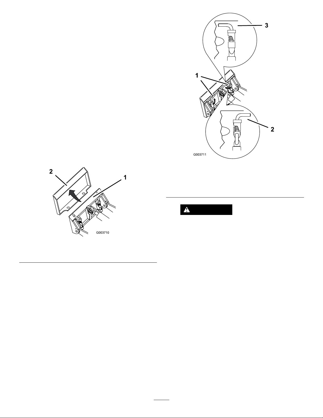
3.Tilttheattachmentmountplateforward.
4.Positionthemountplateintotheupperlipofthe
attachmentreceiverplate(Figure16).
g003711
Figure17
Figure16
1.Mountplate2.Receiverplate
5.Raisetheloaderarmswhiletiltingbackthe
mountplateatthesametime.
Important:Raisetheattachmentenoughto
clearthegroundandtiltthemountplateall
thewayback.
6.Shutofftheengineandremovethekey.
7.Engagethequick-attachpins,ensuringthatthey
arefullyseatedinthemountplate(Figure17).
1.Quick-attachpins
(engagedposition)
2.Disengagedposition
3.Engagedposition
WARNING
Ifyoudonotfullyseatthequick-attach
pinsthroughtheattachmentmountplate,
g003710
theattachmentcouldfalloffthemachine,
crushingyouorbystanders.
Ensurethatthequick-attachpinsarefully
seatedintheattachmentmountplate.
Important:Ifthepinsdonotrotatetothe
engagedposition,themountplateisnot
fullyalignedwiththeholesintheattachment
receiverplate.Checkthereceiverplateand
cleanitifnecessary.
17
Page 18

ConnectingtheHydraulicHoses
WARNING
Hydraulicuidescapingunderpressurecan
penetrateskinandcauseinjury.Fluidinjected
intotheskinmustbesurgicallyremoved
withinafewhoursbyadoctorfamiliarwith
thisformofinjury;otherwise,gangrenemay
result.
•Ensurethatallhydraulic-uidhoses
andlinesareingoodconditionandall
hydraulicconnectionsandttingsaretight
beforeapplyingpressuretothehydraulic
system.
•Keepyourbodyandhandsawayfrom
pinholeleaksornozzlesthateject
high-pressurehydraulicuid.
•Usecardboardorpapertondhydraulic
leaks;neveruseyourhands.
RemovinganAttachment
1.Parkthemachineonalevelsurface.
2.Lowertheattachmenttotheground.
3.Shutofftheengineandremovethekey.
4.Disengagethequick-attachpinsbyturningthem
totheoutside.
5.Iftheattachmentuseshydraulics,movethe
auxiliary-hydraulicsleverforward,backward,
andbacktotheNEUTRALpositiontorelieve
pressureatthehydrauliccouplers.
6.Iftheattachmentuseshydraulics,slidethe
collarsbackonthehydrauliccouplersand
disconnectthem.
Important:Connecttheattachmenthoses
togethertopreventhydraulicsystem
contaminationduringstorage.
7.Installtheprotectivecoversontothehydraulic
couplersonthemachine.
8.Starttheengine,tiltthemountplateforward,and
backthemachineawayfromtheattachment.
CAUTION
Hydrauliccouplers,hydrauliclines/valves,
andhydraulicuidmaybehot.Ifyoucontact
hotcomponents,youmaybeburned.
•Weargloveswhenoperatingthehydraulic
couplers.
•Allowthemachinetocoolbeforetouching
hydrauliccomponents.
•Donottouchhydraulicuidspills.
Iftheattachmentrequireshydraulicsforoperation,
connectthehydraulichosesasfollows:
1.Shutofftheengineandremovethekey.
2.Movetheauxiliary-hydraulicsleverforward,
backward,andbacktotheNEUTRALpositionto
relievepressureatthehydrauliccouplers.
3.Removetheprotectivecoversfromthehydraulic
connectorsonthemachine.
4.Ensurethatallforeignmatteriscleanedfrom
thehydraulicconnectors.
5.Pushtheattachmentmaleconnectorintothe
femaleconnectoronthemachine.
Note:Whenyouconnecttheattachmentmale
connectorrst,yourelieveanypressurebuilt
upintheattachment.
6.Pushtheattachmentfemaleconnectorontothe
maleconnectoronthemachine.
7.Conrmthattheconnectionissecurebypulling
onthehoses.
AfterOperation
AfterOperationSafety
GeneralSafety
•Cleandebrisfromtheattachments,drives,
mufers,andenginetohelppreventres.Clean
upoilorfuelspills.
•Keepallpartsingoodworkingconditionandall
hardwaretightened.
•Donottouchpartsthatmaybehotfromoperation.
Allowthemtocoolbeforeattemptingtomaintain,
adjust,orservicethemachine.
•Usecarewhenloadingorunloadingthemachine
intoatrailerortruck.
MovingaNon-Functioning Machine
Important:Donottoworpullthemachine
withoutrstopeningthetowvalves,oryouwill
damagethehydraulicsystem.
1.Shutofftheengineandremovethekey.
2.Opentherear-accesscover.
3.Usingawrench,turnthetowvalvesonthe
hydraulicpumpstwicecounter-clockwise(Figure
18).
18
Page 19

Figure18
1.Lefttowvalve(righttrack)2.Righttowvalve(lefttrack)
4.Towthemachineasrequired.
5.Afterrepairingthemachine,closethetowvalves
beforeoperatingit.
SelectingaTrailer
WARNING
Loadingamachineontoatrailerortruck
increasesthepossibilityoftip-overandcould
causeseriousinjuryordeath(Figure19).
•Useonlyafull-widthramp;donotuse
individualrampsforeachsideofthe
machine.
•Ensurethatthelengthoframpisatleast4
timesaslongastheheightofthetraileror
truckbedtotheground.Thisensuresthat
rampangledoesnotexceed15degreeson
atground.
g004181
TransportingtheMachine
Useaheavy-dutytrailerortrucktotransportthe
machine.Useafull-widthramp.Ensurethatthetrailer
ortruckhasallthenecessarybrakes,lighting,and
markingasrequiredbylaw.Pleasecarefullyreadall
thesafetyinstructions.Knowingthisinformationcould
helpyouorbystandersavoidinjury.Refertoyour
localordinancesfortrailerandtie-downrequirements.
WARNING
Drivingonthestreetorroadwaywithout
turnsignals,lights,reectivemarkings,ora
slow-moving-vehicleemblemisdangerous
andcanleadtoaccidentscausingpersonal
injury.
Donotdrivethemachineonapublicstreet
orroadway.
1.Full-widthrampinstowed
position
2.Rampisatleast4times
aslongastheheightof
thetrailerortruckbedto
theground
g229507
Figure19
3.H=heightofthetraileror
truckbedtotheground
4.Trailer
19
Page 20

LoadingtheMachine
WARNING
Loadingamachineontoatrailerortruck
increasesthepossibilityoftip-overandcould
causeseriousinjuryordeath.
•Useextremecautionwhenoperatinga
machineonaramp.
•Loadandunloadthemachinewiththe
heavyenduptheramp.
•Avoidsuddenaccelerationordeceleration
whiledrivingthemachineonarampas
thiscouldcausealossofcontrolora
tip-oversituation.
g243576
Figure21
1.Tie-downloops
1.Ifusingatrailer,connectittothetowingvehicle
andconnectthesafetychains.
2.Ifapplicable,connectthetrailerbrakes.
3.Lowertheramp(Figure19).
4.Lowertheloaderarms.
5.Loadthemachineontothetrailerwiththeheavy
enduptheramp,carryingloadslow(Figure20).
•Ifthemachinehasafullload-carrying
attachment(e.g.,bucketoradjustableforks)
oranon-load-carryingattachment(e.g.,
stumpgrinder),drivethemachineforward
uptheramp.
•Ifthemachinehasanemptyload-carrying
attachmentornoattachment,backthe
machineuptheramp.
Figure20
1.Machinewithfull
attachmentor
non-load-carrying
attachment—drivethe
machineforwardupthe
ramp.
2.Machinewithemptyor
noattachment—backthe
machineuptheramp.
UnloadingtheMachine
1.Lowertheramp(Figure20).
2.Unloadthemachinefromthetrailerwiththe
heavyenduptheramp,carryingloadslow
(Figure22).
•Ifthemachinehasafullload-carrying
attachment(e.g.,bucketoradjustableforks)
oranon-load-carryingattachment(e.g.,
stumpgrinder),backitdowntheramp.
•Ifthemachinehasanemptyload-carrying
attachmentornoattachment,driveitforward
downtheramp.
g204458
Figure22
g204457
1.Machinewithfull
attachmentor
non-load-carrying
attachment—backthe
machinedowntheramp.
2.Machinewithemptyor
noattachment—drivethe
machineforwarddownthe
ramp.
LiftingtheMachine
6.Lowertheloaderarmsallthewaydown.
7.Shutofftheengine,removethekey,andengage
theparkingbrake.
8.Usethemetaltie-downloopsonthemachine
tosecurelyfastenthemachinetothetraileror
truckwithstraps,chains,cable,orropes(Figure
21).Refertolocalregulationsfortie-down
requirements.
Youcanliftthemachineusingthetie-down/liftloops
asliftpoints;refertoFigure21.
20
Page 21

Maintenance
Note:Determinetheleftandrightsidesofthemachinefromthenormaloperatingposition.
RecommendedMaintenanceSchedule(s)
MaintenanceService
Interval
Aftertherst8hours
Aftertherst50hours
Beforeeachuseordaily
Every25hours
Every100hours
MaintenanceProcedure
•Replacethehydrauliclter.
•Changetheengineoilandlter.
•Checkandadjustthetracktension.
•Greasethemachine.(Greaseimmediatelyaftereverywashing.)
•Checktheair-lter-serviceindicator.
•Checktheengine-oillevel.
•Drainwaterandothercontaminantsfromthefuellter/waterseparator.
•Cleanthetracks.
•Checkthetracksforexcessivewear(Ifthetracksareworn,replacethem).
•Cleanthescreen,oilcooler,andfrontoftheradiator(moreoftenindirtyordusty
conditions).
•Checkthecoolantlevelintheexpansiontank.
•Checkandcleantheradiatorscreen
•Testtheparkingbrake.
•Removedebrisfromthemachine.
•Checkforloosefasteners.
•Removetheair-cleanercover,cleanoutdebris,andchecktheair-lter-service
indicator.
•Checkthehydraulic-uidlevel.
•Changetheengineoil.(Servicemorefrequentlyifconditionsareextremelydusty
orsandy.)
•Checkandadjustthetracktension.
•Checkthecoolingsystemhoses.
•Checkthehydrauliclinesforleaks,loosettings,kinkedlines,loosemounting
supports,wear,weather,andchemicaldeterioration.
•Checkfordirtbuildupinthechassis.
•Checkthealternator/fanbelttension(refertotheengineowner’smanualfor
instructions).
•Changetheoillter.(Servicemorefrequentlyifconditionsareextremelydusty
Every200hours
Every250hours
Every400hours
Every500hours
Every1,500hours
Yearly
Yearlyorbeforestorage
Every2years
orsandy.)
•Replacethehydrauliclter.
•Checkandgreasetheroadwheels.
•Checkthefuellinesandconnectionsfordeterioration,damage,orlooseconnections.
•Replacethefuelltercanisterandin-linelter.
•Changethehydraulicuid.
•Replacethealternator/fanbelt(refertotheengineowner’smanualforinstructions).
•Replaceallmovinghydraulichoses.
•Changetheenginecoolant(AuthorizedServiceDealeronly).
•Checktheconditionofthehydraulicpumpbelt.
•Checkandadjustthetracktension.
•Touchupchippedpaint.
•Drainandcleanthefueltank(s)—AuthorizedServiceDealeronly .
Important:Refertoyourengineowner’smanualforadditionalmaintenanceprocedures.
21
Page 22

CAUTION
Ifyouleavethekeyintheswitch,someonecouldaccidentlystarttheengineandseriously
injureyouorotherbystanders.
Removethekeyfromtheswitchbeforeyouperformanymaintenance.
Pre-Maintenance
Procedures
MaintenanceSafety
•Parkthemachineonalevelsurface,disengage
theauxiliaryhydraulics,lowertheattachment,
engagetheparkingbrake(ifequipped),shut
offtheengine,andremovethekey .Waitforall
movementtostopandallowthemachinetocool
beforeadjusting,cleaning,storing,orrepairingit.
•Cleanupoilorfuelspills.
•Donotallowuntrainedpersonneltoservicethe
machine.
•Usejackstandstosupportthecomponentswhen
required.
•Carefullyreleasepressurefromcomponentswith
storedenergy.
•Disconnectthebatterybeforemakinganyrepairs;
refertoServicingtheBattery(page31).
•Keepyourhandsandfeetawayfromthemoving
parts.Ifpossible,donotmakeadjustmentswith
theenginerunning.
•Keepallpartsingoodworkingconditionandall
hardwaretightened.Replaceallwornordamaged
decals.
•Donottamperwiththesafetydevices.
•UseonlyToro-approvedattachments.
Attachmentscanchangethestabilityandthe
operatingcharacteristicsofthemachine.Y oumay
voidthewarrantyifyouusethemachinewith
unapprovedattachments.
•UseonlygenuineTororeplacementparts.
•Ifanymaintenanceorrepairrequirestheloader
armstobeintheraisedposition,securethearms
intheraisedpositionwiththehydraulic-cylinder
lock(s).
InstallingtheCylinderLock
1.Removetheattachment.
2.Raisetheloaderarmstothefullyraisedposition.
3.Shutofftheengineandremovethekey.
4.Removethelynchpinsecuringthecylinderlock
totheloaderarm(Figure23).
Figure23
1.Cylinderlock
2.Liftcylinder
5.Lowerthecylinderlockoverthecylinderrodand
secureitwiththelynchpin(Figure23).
6.Slowlylowertheloaderarmsuntilthecylinder
lockcontactsthecylinderbodyandrodend.
3.Lynchpin
g004182
UsingtheCylinderLock
WARNING
Theloaderarmsmaylowerwhenintheraised
position,crushinganyoneunderthem.
Installthecylinderlock(s)beforeperforming
maintenancethatrequiresraisedloaderarms.
22
Page 23

RemovingandStoringthe CylinderLock
Important:Removethecylinderlockfromtherod
andfullysecureitinthestoragepositionbefore
operatingthemachine.
1.Starttheengine.
2.Raisetheloaderarmstothefullyraisedposition.
3.Shutofftheengineandremovethekey.
4.Removethelynchpinsecuringthecylinderlock.
5.Rotatethecylinderlockuptotheloaderarm
andsecureitwiththelynchpin.
6.Lowertheloaderarms.
AccessingInternal Components
WARNING
Openingorremovingcovers,hoods,and
screenswhiletheengineisrunningcould
allowyoutocontactmovingparts,seriously
injuringyou.
Beforeopeninganyofthecovers,hoods,and
screens,shutofftheengine,removethekey
fromthekeyswitch,andallowtheengineto
cool.
OpeningtheHood
1.Loosenthehood-lockingscrew(Figure24)
Figure24
1.Hood3.Hood-lockingscrew
2.Hood-latchlever
2.Turnthehoodlatchclockwise(Figure24).
3.Swingthehoodup(Figure24).
23
g009691
Page 24

ClosingtheHood
ClosingtheRear-AccessCover
1.Liftuponthetabsecuringtheproprod(Figure
25)
Figure25
1.Prop-rodtab
2.Lowerthehoodandsecureitbypushingdown
onthefrontofthehooduntilitlocksinplace.
1.Movetherear-accesscoverinplaceoverthe
backofthemachine;ensurethatthetabsline
upintheslots.
2.Pushtheaccesscoverforward,liningupthe
hand-knobscrewswiththethreadedholesin
themachine.
3.Screwthehandknobstighttosecurethe
rear-accesscoverinplace.
RemovingtheSideScreens
1.Openthehood.
2.Slidethesidescreens(Figure27)upandoutof
theslotsinthefrontscreenandframe.
g007360
3.Tightenthehood-lockingscrewtosecurethe
latch(Figure24).
OpeningtheRear-AccessCover
1.Unscrewthe2handknobssecuringthe
rear-accesscovertothemachine(Figure26).
Figure26
1.Handknobs
2.Tilttherear-accesscoverdownandremoveto
accesstheinternalcomponents(Figure26).
g004352
Figure27
1.Sidescreen
InstallingtheSideScreens
Slidethesidescreensintoplaceintheslotsinthe
frontscreenandframe.
g244210
24
Page 25

Lubrication
EngineMaintenance
GreasingtheMachine
ServiceInterval:Beforeeachuseordaily(Grease
immediatelyaftereverywashing.)
GreaseType:General-purposegrease.
1.Parkthemachineonalevelsurface,engage
theparkingbrake(ifequipped),andlowerthe
loaderarms.
2.Shutofftheengineandremovethekey.
3.Cleanthegreasettingswitharag.
4.Connectagreaseguntoeachtting(Figure28
andFigure29).
EngineSafety
•Shutofftheenginebeforecheckingtheoilor
addingoiltothecrankcase.
•Donotchangetheenginegovernorsettingor
overspeedtheengine.
•Keepyourhands,feet,face,clothing,andother
bodypartsawayfromthemuferandotherhot
surfaces.
ServicingtheAirCleaner
ServiceInterval:Beforeeachuseordaily—Check
theair-lter-serviceindicator.
Every25hours—Removetheair-cleanercover,
cleanoutdebris,andchecktheair-lter-service
indicator.
ServicingtheAir-CleanerCover andBody
Important:Replacetheair-cleanerlteronly
whentheserviceindicatorshowsred(Figure30).
Changingtheairlterbeforeitisnecessaryonly
increasesthechanceofdirtenteringtheengine
whenyouremovethelter.
Figure28
Figure29
5.Pumpgreaseintothettingsuntilgreasebegins
tooozeoutofthebearings(approximately3
pumps).
6.Wipeupanyexcessgrease.
g004235
g004209
1.Parkthemachineonalevelsurface,engage
theparkingbrake(ifequipped),andlowerthe
loaderarms.
2.Shutofftheengineandremovethekey.
3.Openthehoodandsecuretheproprod(if
applicable).
4.Checktheair-cleanerbodyfordamagethat
couldcauseanairleak.Checkthewholeintake
systemforleaks,damage,orloosehoseclamps.
Replaceorrepairanydamagedcomponents.
5.Releasethelatchesontheaircleanerandpull
theair-cleanercoverofftheair-cleanerbody
(Figure30).
Important:Donotremovetheairlter.
25
Page 26

1.Dustcap
2.Latch
3.Air-cleanercover
Figure30
4.Primarylter
5.Air-lterbody
6.Serviceindicator
Important:Donotpressonthesoftinside
areaofthelter.
4.Installtheair-cleanercoverwiththedustcap
orienteddownwardandsecurethelatches
(Figure30).
5.Closethehood.
ServicingtheEngineOil
ServiceInterval:Beforeeachuseordaily—Check
theengine-oillevel.
g031236
Aftertherst50hours—Changetheengineoil
andlter.
Every100hours—Changetheengineoil.
(Servicemorefrequentlyifconditionsare
extremelydustyorsandy .)
6.Squeezethedustcapsidestoopenitandknock
thedustout.
7.Cleantheinsideoftheair-cleanercoverwith
compressedairthatisunder205kPa(30psi).
Important:Donotusecompressedairon
theair-cleanerbody.
8.Checktheserviceindicator.
•Iftheserviceindicatorisclear,installthe
air-cleanercoverwiththedustcaporiented
downwardandsecurethelatches(Figure
30).
•Iftheserviceindicatorisred,replacethe
airlterasdescribedinReplacingtheFilter
(page26).
ReplacingtheFilter
Important:Topreventenginedamage,always
operatetheenginewiththeairlterandcover
installed.
1.Gentlyslidethelteroutoftheair-cleanerbody
(Figure30).
Every200hours—Changetheoillter.(Service
morefrequentlyifconditionsareextremely
dustyorsandy.)
Engine-OilSpecications
OilType:Detergentdieselengineoil(APIservice
CH-4orhigher)
CrankcaseCapacity:withlter,3.7L(1.0USgallon)
Viscosity:Seetablebelow
Note:Avoidknockingthelterintothesideof
thebody.
Important:Donotattempttocleanthelter.
2.Inspectthenewlterfortears,anoilylm,or
damagetotherubberseal.Lookintothelter
whileshiningabrightlightontheoutsideofthe
lter;holesinthelterappearasbrightspots.
Ifthelterisdamaged,donotuseit.
3.Carefullyinstallthelter(Figure30).
Note:Ensurethatthelterisfullyseated
bypushingontheouterrimofthelterwhile
installingit.
g001061
Figure31
26
Page 27

CheckingtheEngine-OilLevel
ChangingtheEngineOil
1.Parkthemachineonalevelsurface,engagethe
parkingbrake,andlowertheloaderarms.
2.Shutofftheengine,removethekey,andallow
theenginetocool.
3.Openthehood.
4.Cleantheareaaroundtheoildipstick(Figure
32).
1.Starttheengineandletitrunfor5minutes.
Note:Thiswarmstheoilsothatitdrainsbetter.
2.Parkthemachinesothatthedrainsideisslightly
lowerthantheoppositesidetoensurethatthe
oildrainscompletely.
3.Lowertheloaderarms,engagetheparking
brake,shutofftheengine,andremovethekey.
4.Removethedrainplug(Figure33).
Figure32
1.Oildipstick2.Oil-llcap
5.Pulloutthedipstickandwipethemetalend
clean(Figure32).
6.Slidethedipstickfullyintothedipsticktube
(Figure32).
7.Pullthedipstickoutandlookatthemetalend.
8.Iftheoillevelislow(belowthebottomhole),
cleanaroundtheoil-llcapandremovethecap
(Figure32).
9.Slowlypouronlyenoughoilintothevalve
covertoraisetheleveltotheupperholeonthe
dipstick.
Important:Donotoverllthecrankcase
withoiltopreventdamagingtheengine.
10.Replacethellcapanddipstick.
11.Closethehood.
g004227
g004353
Figure33
1.Oildrainplug
5.Whentheoilhasdrainedcompletely ,replace
theplug.
Note:Disposeoftheusedoilatacertied
recyclingcenter.
6.Removethellcap(Figure32)andslowlypour
approximately80%ofthespeciedamountofoil
inthroughthevalvecover.
7.Checktheoillevel.
8.Slowlyaddadditionaloiltobringtheleveltothe
upperholeonthedipstick.
9.Replacethellcap.
27
Page 28

ChangingtheOilFilter
1.Draintheoilfromtheengine;refertoChanging
theEngineOil(page27).
FuelSystem
Maintenance
2.Whentheoilhasdrainedcompletely ,replace
theplug.
Note:Disposeoftheusedoilatacertied
recyclingcenter.
3.Placeashallowpanorragunderthelterto
catchoil.
4.Removetheoldlter(Figure34)andwipethe
surfaceofthelteradaptergasket.
DANGER
Incertainconditions,fuelisextremely
ammableandhighlyexplosive.Areor
explosionfromfuelcanburnyouandothers
andcandamageproperty.
RefertoFuelSafety(page13)foracomplete
listoffuelrelatedprecautions.
CheckingtheFuelLines andConnections
ServiceInterval:Every400hours/Yearly(whichever
comesrst)
Inspectthefuellinesandconnectionsfordeterioration,
damage,orlooseconnections.Tightenanyloose
connectionsandcontactyourAuthorizedService
Dealerforassistanceinxingdamagedfuellines.
DrainingtheFuel
Figure34
1.Oillter
5.Pournewoilofthepropertypethroughthe
centerholeofthelter.Stoppouringwhenthe
oilreachesthebottomofthethreads.
6.Allow1to2minutesfortheoiltobeabsorbed
byltermaterial,thenpourofftheexcessoil.
7.Applyathincoatofnewoiltotherubbergasket
onthereplacementlter.
8.Installthereplacementoilltertothelter
adapter.Turntheoillterclockwiseuntilthe
rubbergasketcontactsthelteradapter,then
tightenthelteranadditional1/2turn.
9.Removethellcap(Figure32)andslowlypour
approximately80%ofthespeciedamountofoil
inthroughthevalvecover.
Filter/WaterSeparator
ServiceInterval:Beforeeachuseordaily
g004354
1.Parkthemachineonalevelsurface,engagethe
parkingbrake,andlowertheloaderarms.
2.Shutofftheengineandremovethekey.
3.Locatethefuellterontherightsideofthe
engine(Figure35)andplaceacleancontainer
underit.
10.Checktheoillevel.
11.Slowlyaddadditionaloiltobringtheleveltothe
upperholeonthedipstick.
12.Replacethellcap.
28
Page 29

Figure35
1.Fuel-ltercanister/water
separator
2.Drainvalve
4.Loosenthedrainvalveonthebottomofthelter
canisterandallowthewatertodrain.
5.Whennished,tightenthedrainvalve.
3.Hoseclamps
4.In-linelter
10.Locatethein-lineltertotheleftofthefuellter
canister(Figure35)andnotethedirectionof
owarrowonthesideofthein-linelter.
11.Opentheclampsoneachendofthein-linelter
andslidethehosesoffit(Figure35).Discard
thelter.
12.Slidethehosesovertheendofanewlter
(Figure35),ensuringthatthearrowonthelter
ispointingtowardtheengineorelectricfuel
pump.
13.Securethehosestothelterwiththehose
clamps.
14.Closetherear-accesscoverandsecurewiththe
fastener(s).
BleedingtheFuelSystem
Youmustbleedthefuelsystembeforestartingthe
g009626
engineifanyofthefollowingsituationshaveoccurred:
•Initialstartupofanewmachine
•Theenginehasceasedrunningduetoalackof
fuel.
•Maintenancehasbeenperformedonfuelsystem
components(e.g.,lterreplaced).
1.Parkthemachineonalevelsurface,lowerthe
loaderarms,andshutofftheengine.
2.Ensurethatthefueltankisatleasthalffull.
ReplacingtheFuelFilter CanisterandIn-LineFilter
ServiceInterval:Every400hours
1.Parkthemachineonalevelsurface,engagethe
parkingbrake,andlowertheloaderarms.
2.Shutofftheengineandremovethekey.
3.Opentherear-accesscover;refertoOpening
theRear-AccessCover(page24).
4.Locatethefuelltersontherightsideofthe
engine(Figure35)andplaceacleancontainer
underit.
5.Cleantheareawheretheltercanistermounts
(Figure35).
6.Removetheltercanisterandcleanthe
mountingsurface(Figure35).
7.Lubricatethegasketonthenewltercanister
withcleanoil.
8.Fillthecanisterwithfuel.
9.Installtheltercanisterbyhanduntilthegasket
contactsthemountingsurface,thenrotateitan
additional1/2turn(Figure35).
3.Openthehood.
4.Opentheair-bleedscrewonthefuel-injection
pump(Figure36).
g003880
Figure36
1.Air-bleedscrew
29
Page 30

5.TurnthekeyinthekeyswitchtotheONposition.
Theelectricfuelpumpbeginsoperation,thereby
forcingairoutaroundtheair-bleedscrew.Leave
thekeyintheONpositionuntilasolidstreamof
fuelowsoutaroundthescrew.
ElectricalSystem
Maintenance
6.TightenthescrewandturnthekeytotheOFF
position.
Note:Theengineshouldstartaftertheabove
bleedingproceduresarefollowed.However,ifengine
doesnotstart,airmaybetrappedbetweeninjection
pumpandinjectors;contactyourAuthorizedService
Dealer.
DrainingtheFuelTank(s)
ServiceInterval:Every2years
HaveanAuthorizedServiceDealerdrainandclean
thefueltank(s).
ElectricalSystemSafety
•Disconnectthebatterybeforerepairingthe
machine.Disconnectthenegativeterminalrst
andthepositivelast.Connectthepositiveterminal
rstandthenegativelast.
•Chargethebatteryinanopen,well-ventilated
area,awayfromsparksandames.Unplugthe
chargerbeforeconnectingordisconnectingthe
battery.Wearprotectiveclothinganduseinsulated
tools.
•Batteryacidispoisonousandcancauseburns.
Avoidcontactwithskin,eyes,andclothing.Protect
yourface,eyes,andclothingwhenworkingwitha
battery.
•Batterygasescanexplode.Keepcigarettes,
sparks,andamesawayfromthebattery.
WARNING
CALIFORNIA
Proposition65Warning
Batteryposts,terminals,andrelated
accessoriescontainleadandlead
compounds,chemicalsknownto
theStateofCaliforniatocause
cancerandreproductiveharm.Wash
handsafterhandling.
30
Page 31

ServicingtheBattery
Alwayskeepthebatterycleanandfullycharged.Use
apapertoweltocleanthebatterycase.Ifthebattery
terminalsarecorroded,cleanthemwithasolutionof
4partswaterand1partbakingsoda.Applyalight
coatingofgreasetothebatteryterminalstoreduce
corrosion.
Specications:12V ,585A(coldcranking)
RemovingtheBattery
WARNING
Batteryterminalsormetaltoolscouldshort
againstmetalmachinecomponents,causing
sparks.Sparkscancausethebatterygasses
toexplode,resultinginpersonalinjury.
•Whenremovingorinstallingthebattery,
donotallowthebatteryterminalstotouch
anymetalpartsofthemachine.
g243600
Figure38
1.Positivecable4.Negativecable
2.Bar5.Battery
3.Boltandwasher
•Donotallowmetaltoolstoshortbetween
thebatteryterminalsandmetalpartsofthe
machine.
1.Parkthemachineonalevelsurface,engage
theparkingbrake(ifequipped),andlowerthe
loaderarms.
2.Shutofftheengineandremovethekey.
3.Opentherear-accesscover;refertoOpening
theRear-AccessCover(page24).
4.Removethebattery-accesspanel
6.Disconnectthenegative(black)groundcable
fromthebatterypost(Figure38).Retainthe
fasteners.
7.Slidetherubbercoveroffthepositive(red)
cable.
8.Disconnectthepositive(red)cablefromthe
batterypost(Figure38).Retainthefasteners.
9.Liftthebatteryoutofthechassis.
ChargingtheBattery
Important:Alwayskeepthebatteryfullycharged
(1.265specicgravity).Thisisespecially
importanttopreventbatterydamagewhenthe
temperatureisbelow0°C(32°F).
1.Removethebatteryfromthemachine;referto
RemovingtheBattery(page31).
2.Chargethebatteryfor10to15minutesat25to
30Aor30minutesat4to6A(Figure39).Do
notoverchargethebattery .
Figure37
1.Bolt(3)
5.Removethebolt,washer,andbarsecuringthe
battery(Figure38).
2.Battery-accesspanel
g244209
31
Page 32

1.Positivebatterypost
2.Negativebatterypost
Figure39
3.Red(+)chargerlead
4.Black(-)chargerlead
CleaningtheBattery
Note:Keeptheterminalsandtheentirebatterycase
clean,becauseadirtybatterydischargesslowly.
1.Parkthemachineonalevelsurface,engage
theparkingbrake(ifequipped),andlowerthe
loaderarms.
2.Shutofftheengineandremovethekey.
3.Removethebatteryfromthemachine;
RemovingtheBattery(page31).
4.Washtheentirecasewithasolutionofbaking
g003792
sodaandwater.
5.Rinsethebatterywithclearwater.
6.Coatthebatterypostsandcableconnectorswith
Grafo112X(skin-over)grease(T oroPartNo.
505-47)orpetroleumjellytopreventcorrosion.
3.Whenthebatteryisfullycharged,unplug
thechargerfromtheelectricaloutlet,then
disconnectthechargerleadsfromthebattery
posts(Figure39).
7.Installthebattery;refertoInstallingtheBattery
(page32).
InstallingtheBattery
1.Usingthefastenerspreviouslyremoved,install
thepositive(red)batterycabletothepositive(+)
batteryterminal(Figure38).
2.Slidetheredterminalbootontothepositive
batterypost.
3.Usingthefastenerspreviouslyremoved,install
thenegative(black)batterycabletothenegative
(-)batteryterminal(Figure38).
4.Securethebatteryusingthebar,bolt,and
washer(Figure38).
Important:Ensurethatthebatterycablesdo
notcontactanysharpedgesoreachother.
5.Installthebattery-accesspanel(Figure37).
6.Closetherear-accesscover;refertoClosingthe
Rear-AccessCover(page24).
ServicingaReplacementBattery
Theoriginalbatteryismaintenance-freeanddoesnot
requireservice.Forservicingareplacementbattery,
refertothebatterymanufacturer’sinstructions.
32
Page 33

ServicingtheFuses
Theelectricalsystemisprotectedbyfuses.Itrequires
nomaintenance;however,ifafuseblows,checkthe
component/circuitforamalfunctionorashort.Figure
40illustratesthefuseblockandidentiesthefuse
positions.
g004984
Figure41
Figure40
1.Fuse(30A)3.Fuse(10A)
2.Empty
4.Openpositionforoptional
accessories
Note:Ifthemachinedoesnotstart,eitherthemain
circuitorcontrolpanel/relayfusecouldbeblown.
Toaccessthefuses,youmustremovethefusepanel,
asfollows:
1.Parkthemachineonalevelsurface,engage
theparkingbrake(ifequipped),andlowerthe
loaderarms.
2.Shutofftheengineandremovethekey.
3.Openthehood.
4.Pullthehairpincotterfromthebottomendofthe
hoodprop-rodandslidetheproprodoutofthe
retainingbracketsandtheprop-rodtab(Figure
41).
1.Prop-rodtab4.Retaining
2.Retainingbracket—top5.Hairpincotter
3.Prop-rod
bracket—bottom
5.Removethe4screwssecuringthefusepanel
andthenpullthepaneloutanduptoremove
g004355
it(Figure42).
1.Fusepanel
g004985
Figure42
2.Screw
6.Checkthefuses.
7.Installthefusepanelusingthe4screws
removedpreviously.
8.Installtheprop-rodintotheretainingbrackets
andprop-rodtabandsecureitwiththehairpin
cotter(Figure41).
33
9.Closethehood.
Page 34

DriveSystem
Maintenance
ServicingtheTracks
ServiceInterval:Aftertherst50hours—Checkand
adjustthetracktension.
Beforeeachuseordaily—Cleanthetracks.
Beforeeachuseordaily—Checkthetracksfor
excessivewear(Ifthetracksareworn,replace
them).
Every100hours—Checkandadjustthetrack
tension.
Every250hours/Y early(whichevercomes
rst)—Checkandgreasetheroadwheels.
g004200
Figure43
1.Track3.Roadwheels
2.Drivesprocket4.Tensionwheel
CleaningtheTracks
1.Parkthemachineonalevelsurfaceandengage
theparkingbrake.
2.Withthebucketinstalledandpointingdown,
loweritintothegroundsothatthefrontofthe
tractionunitliftsoffthegroundafewcentimeters
(inches).
3.Shutofftheengineandremovethekey.
4.Usingawaterhoseorpressurewasher,remove
dirtfromeachtracksystem.
Important:Ensurethatyouusehigh-pressure
watertowashonlythetrackarea.Donotuse
ahigh-pressurewashertocleantherestofthe
machine.Donotusehighpressurewaterbetween
thedrivesprocketandthemachineoryoumay
damagethemotorseals.High-pressurewashing
candamagetheelectricalsystemandhydraulic
valvesordepletegrease.
Important:Ensurethatyoufullycleantheroad
wheels,thetensionwheel,andthedrivesprocket
(Figure43).Theroadwheelsshouldrotatefreely
whenclean.
AdjustingtheTrackTension
Thereshouldbe7cm(2-3/4inches)betweenthe
tensionnutandthebackofthetensiontube(Figure
44).Ifnot,adjustthetracktensionusingthefollowing
procedure:
g004201
Figure44
1.7cm(2-3/4inches)
1.Parkthemachineonalevelsurface,engagethe
parkingbrake,andlowertheloaderarms.
2.Shutofftheengineandremovethekey.
3.Lift/supportthesideoftheunittobeworkedon
sothatthetrackisofftheground.
4.Removethelockingboltandnut(Figure45).
34
Page 35

Figure45
1.Lockingbolt3.Tensiontube
2.Tensioningscrew4.Tensionwheel
5.Usinga1/2-inchdriveratchet,turnthe
tensioningscrewcounterclockwiseuntilthe
distancebetweenthetensionnutandtheback
ofthetensiontube(Figure44)is7cm(2-3/4
inches).
6.Aligntheclosestnotchinthetensionscrewto
thelockingboltholeandsecurethescrewwith
thelockingboltandnut(Figure45).
7.Lowerthetractionunittotheground.
ReplacingtheTracks
ReplacingNarrow-WidthTracks
Whenthetracksarebadlyworn,replacethem.
Note:Y ouhavenarrow-widthtracksifthefront
tensionwheelsaremountedinsideaforkontheend
ofthetensiontube(Figure46).
1.Parkthemachineonalevelsurface,engagethe
parkingbrake,andlowertheloaderarms.
2.Shutofftheengineandremovethekey.
3.Lift/supportthesideoftheunittobeworkedon
sothatthetrackis8to10cm(3to4inches)
offtheground.
4.Removethelockingboltandnut(Figure45).
5.Usinga1/2-inchdriveratchet,releasethe
drivetensionbyturningthetensioningscrew
clockwise(Figure45andFigure46).
g004202
g004203
Figure46
1.Track5.Tracklug
2.Socketwrench(1/2inch)
3.Tensionwheel
4.Tensiontube8.Roadwheels
6.Drivesprocket
7.Sprocketcog
6.Pushthetensionwheeltowardtherearofthe
unittomovethetensiontubeagainsttheframe
(Figure46).
Ifitdoesnottouchtheframe,continueturning
thetensioningscrewuntilitdoes.
7.Beginremovingthetrackatthetopofthe
tensionwheel,peelingitoffthewheelwhile
rotatingthetrackforward.
8.Whenthetrackisoffthetensionwheel,remove
itfromthedrivesprocketandroadwheels
(Figure46).
9.Beginningatthedrivesprocket,coilthenew
trackaroundthesprocket,ensuringthatthelugs
onthetracktbetweenthecogsonthesprocket
(Figure46).
10.Pushthetrackunderandbetweentheroad
wheels(Figure46).
11.Startingatthebottomofthetensionwheel,
installthetrackaroundthewheelbyrotating
thetrackrearwardwhilepushingthelugsinto
thewheel.
12.Turnthetensioningscrewcounterclockwiseuntil
thedistancebetweenthetensionnutandthe
backofthetensiontube(Figure44)is7cm
(2-3/4inches).
13.Aligntheclosestnotchinthetensionscrewto
thelockingboltholeandsecurethescrewwith
thelockingboltandnut.
14.Lowerthetractionunittotheground.
35
Page 36

15.Repeatsteps3through14toreplacetheother
track.
ReplacingWide-WidthTracks
Whenthetracksarebadlyworn,replacethem.
Note:Y ouhavewide-widthtracksifthefronttension
wheelsaremountedonthesidesoftheendofthe
tensiontube(Figure47).
1.Parkthemachineonalevelsurface,engagethe
parkingbrake,andlowertheloaderarms.
2.Shutofftheengineandremovethekey.
3.Lift/supportthesideoftheunittobeworkedon
sothatthetrackis8to10cm(3to4inches)
offtheground.
4.Removethelockingboltandnut(Figure45).
5.Usinga1/2-inchdriveratchet,releasethe
drivetensionbyturningthetensioningscrew
clockwise(Figure45andFigure47).
9.Removethenutsecuringtheinnertension
wheelandremovethewheel(Figure47).
10.Pullthe4largewashersoutofthe2wheels,1
oneachsideofeachwheel.
11.Cleantheoldgreaseanddirtoutofthearea
betweenwherethewasherswereinstalledand
thebearingsinsidethewheels,thenllthisarea
oneachsideofeachwheelwithgrease.
12.Installthelargewashersonthewheelsoverthe
grease.
13.Installtheinnertensionwheelandsecureitwith
thenutremovedpreviously(Figure47).
14.T orquethenutto407N∙m(300ft-lb).
15.Installthenewtrack,ensuringthatthelugsin
thetracktbetweenthecogsinthemiddleof
thedrivesprocket(Figure47).
16.Installtheoutertensionwheelandsecureitwith
thenutremovedpreviously(Figure47).
17.T orquethenutto407N∙m(300ft-lb).
18.Turnthetensioningscrewcounterclockwiseuntil
thedistancebetweenthetensionnutandthe
backofthetensiontube(Figure44)is7cm
(2-3/4inches).
19.Aligntheclosestnotchinthetensionscrewto
thelockingboltholeandsecurethescrewwith
thelockingboltandnut.
20.Lowerthetractionunittotheground.
21.Repeatsteps3through20toreplacetheother
track.
Figure47
1.Track6.Tracklug
2.Socketwrench(1/2inch)
3.Tensionwheelnut
4.Outertensionwheel
5.Tensiontube10.Innertensionwheel
7.Drivesprocket
8.Sprocketcog
9.Roadwheels
6.Pushthetensionwheeltowardtherearofthe
unittomovethetensiontubeagainsttheframe
(Figure47).
Ifitdoesnottouchtheframe,continueturning
thetensioningscrewuntilitdoes.
7.Removethenutsecuringtheoutertension
wheelandremovethewheel(Figure47).
8.Removethetrack(Figure47).
MaintainingtheRoadWheels
1.Removethetracks;refertoReplacingthe
Tracks(page35).
2.Removethe4boltssecuringeachlowertrack
g004204
guidewhichcontainstheroadwheels,and
removethem(Figure48).
Figure48
1.Roadwheels
2.Lowertrackguide
3.Trackguidebolts(only2
g004205
shown)
36
Page 37

3.Removethesnapringandcapfromaroad
wheel(Figure49).
Figure49
1.Roadwheel4.Roadwheelcap
2.Gasket5.Snapring
3.Bolt6.Addgreaseunderthecap
CoolingSystem
Maintenance
CoolingSystemSafety
•Swallowingenginecoolantcancausepoisoning;
keepoutofreachfromchildrenandpets.
•Dischargeofhot,pressurizedcoolantortouching
ahotradiatorandsurroundingpartscancause
severeburns.
–Alwaysallowtheenginetocoolatleast15
g004206
ServicingtheCooling
minutesbeforeremovingtheradiatorcap.
–Usearagwhenopeningtheradiatorcap,and
openthecapslowlytoallowsteamtoescape.
4.Checkthegreaseunderthecapandaround
thegasket(Figure49).Ifitisdirty,gritty,or
depleted,cleanoutallofthegrease,replacethe
gasket,andaddnewgrease.
5.Ensurethattheroadwheelturnssmoothlyon
thebearing.Ifitisfrozen,replacetheroadwheel
asdescribedintheRoadWheelKitInstallation
InstructionsorcontactyourAuthorizedService
Dealerforrepair.
6.Placethegreasedroadwheelcapoverthebolt
head(Figure46).
7.Securetheroadwheelcapwiththesnapring
(Figure46).
8.Repeatsteps3through7fortheotherroad
wheels.
9.Installeachtrackguidetothetraction-unitframe
usingthefastenersyouremovedpreviously.
Torquetheboltsto91to112N∙m(67to83ft-lb).
10.Installthetracks;refertoReplacingtheTracks
(page35).
System
ServiceInterval:Beforeeachuseordaily—Clean
thescreen,oilcooler,andfrontof
theradiator(moreoftenindirtyor
dustyconditions).
Beforeeachuseordaily—Checkthecoolant
levelintheexpansiontank.
Every100hours—Checkthecoolingsystem
hoses.
Yearly—Changetheenginecoolant(Authorized
ServiceDealeronly).
DANGER
Therotatingshaftandfancancausepersonal
injury.
•Donotoperatethemachinewithoutthe
coversinplace.
•Keepyourngers,hands,andclothing
clearoftherotatingfananddriveshaft.
•Parkthemachineonalevelsurface,lower
theloaderarms,engagetheparkingbrake,
shutofftheengine,andremovethekey
fromthekeyswitchbeforeperforming
maintenance.
CleaningtheRadiatorScreen
ServiceInterval:Beforeeachuseordaily
Removeanybuildupofgrass,dirtorotherdebrisfrom
theradiatorscreenwithcompressedair.
37
Page 38

Checking,Adding,andBleeding theEngineCoolant
Thecoolingsystemislledwitha50/50solutionof
waterandpermanentethylene-glycolantifreeze.
1.Parkthemachineonalevelsurface,lowerthe
loaderarms,engagetheparkingbrake,and
shutofftheengine.
2.Removethekeyfromthekeyswitchandallow
theenginetocool.
3.Checkthecoolantlevelofcoolantinthe
expansiontank(Figure50).
Thecoolantlevelshouldbeatorabovethemark
onthesideofthetank.
Figure50
1.Expansiontank2.Fullmark
g004230
Figure51
1.Expansiontank3.Topcoolant-bleedvalve
2.Coolant-llcapandller
neck
4.Frontcoolant-bleedvalve
B.Openthefrontandtopcoolant-bleedvalves
(Figure51).
C.Pourcoolantintothecoolant-llerneckuntil
thecoolantbeginstocomeoutofthefront
coolant-bleedvalve(Figure51).
D.Closethefrontcoolant-bleedvalve(Figure
51).
E.Pourcoolantintothecoolant-llerneckuntil
thecoolantbeginstocomeoutofthetop
coolant-bleedvalve(Figure51).
F.Closethetopcoolant-bleedvalve(Figure
g004351
51).
G.Pourcoolantintothecoolant-llerneckuntil
thecoolantlevelcomesintothellerneck
(Figure51).
4.Ifthecoolantlevelislow,completethefollowing
procedure:
A.Removethecoolant-llcap(Figure51).
H.Installthecoolant-llcap(Figure51).
I.Addcoolantintotheexpansiontankuntil
itreachestheFullmarkonthesideofthe
tank(Figure50).
5.Installtheexpansiontankcap.
ChangingtheEngineCoolant
HaveanAuthorizedServiceDealerchangetheengine
coolantyearly.
Ifyouneedtoaddenginecoolant,refertoChecking,
Adding,andBleedingtheEngineCoolant(page38).
38
Page 39

BrakeMaintenance
BeltMaintenance
TestingtheParkingBrake
ServiceInterval:Beforeeachuseordaily
1.Engagetheparking-brake;referto
Parking-BrakeLever(page12).
2.Starttheengine.
3.Slowlyattempttodrivethemachineforwardor
rearward.
Note:Themachinemayrollslightlybeforethe
brakesengageinthedrivesprocket.
4.Ifthebrakesdonotholdthemachineafterthe
initialslightmovement,contactyourAuthorized
ServiceDealerforservice.
CheckingtheConditionof theHydraulicPumpBelt
ServiceInterval:Yearly
Checktheconditionofthehydraulicpumpbelt(Figure
52)yearly .HaveanAuthorizedServiceDealer
replaceitifitbecomesdamagedorworn.
g004356
Figure52
1.Hydraulicpumpbelt
39
Page 40

ControlsSystem
Maintenance
AdjustingtheControls
Thefactoryadjuststhecontrolsbeforeshippingthe
machine.However,aftermanyhoursofuse,you
mayneedtoadjustthetractioncontrolalignment,
theNEUTRALpositionofthetractioncontrol,andthe
trackingofthetractioncontrolinthefullforward
position.
1.Tractioncontrol
g004191
Figure54
2.Stem,bolt,andnut
Important:Toadjustthecontrolsproperly,
completeeachprocedureintheorderlisted.
AdjustingtheTractionControl Alignment
Ifthetractioncontrolbardoesnotrestushand
squarewiththereferencebarwheninthefull
backwardposition,immediatelycompletethefollowing
procedure:
1.Parkthemachineonalevelsurface,engagethe
parkingbrake,andlowertheloaderarms.
2.Shutofftheengineandremovethekey.
3.Pullstraightbackonthetractioncontrolsothe
frontofthecontrolcontactsthereferencebar
(Figure53).
5.Adjustthetractioncontrolsothatitrestsush
againstthereferencebarwhenyoupullit
straightback(Figure54andFigure55).
g004192
Figure55
6.Tightentheangenutandboltinthetraction
controlstem.
AdjustingtheTractionControl NeutralPosition
Ifthemachinecreepsforwardorbackwardwhen
thetractioncontrolisintheNEUTRALpositionand
theunitiswarm,immediatelycompletethefollowing
procedure:
Figure53
1.Frontofthecontrol(outof
alignment)
4.Ifthefrontofthetractioncontroldoesnotrest
squareandushwiththereferencebar,loosen
theangenutandboltinthestemofthetraction
control(Figure54).
2.Referencebar
1.Lift/supportthemachinesothatbothtracksare
offtheground.
g004190
2.Opentherear-accesscover.
3.Loosenthejamnutsonthetractionrods,under
thecontrolpanel(Figure56).
40
Page 41

Figure56
1.Tractionrod2.Jamnut
4.Startthetractionunitandsetthethrottleto
about1/3openposition.
AdjustingtheTrackingofthe TractionControl,FullForward Position
Ifthemachinedoesnotdrivestraightwhenyou
holdthetractioncontrolagainstthereferencebar,
completethefollowingprocedure:
1.Drivethemachinewiththetractioncontrol
againstthereferencebar,notingwhichdirection
thetractionunitveers.
2.Releasethetractioncontrol.
3.Ifthetractionunitveerstotheleft,loosenthe
rightjamnutandadjustthetrackingsetscrew
onthefrontofthetractioncontrol(Figure57).
4.Ifthetractionunitveerstotheright,loosenthe
leftjamnutandadjustthetrackingsetscrewon
g013014
thefrontofthetractioncontrol(Figure57).
WARNING
Whenthemachineisrunning,youcould
becaughtandinjuredinmovingpartsor
burnedonhotsurfaces.
Stayawayfrompinchpoints,moving
parts,andhotsurfaceswhenadjusting
therunningmachine.
5.Ifthelefttrackmoves,lengthenorshortenthe
righttractionroduntilthetrackstopsmoving.
6.Iftherighttrackmoves,lengthenorshortenthe
lefttractionroduntilthetrackstopsmoving.
7.Tightenthejamnuts.
8.Closetherear-accesscover.
9.Shutofftheengineandlowerthemachineto
theground.
10.Drivethemachineinfullreverse,checkingto
seeiftheunittracksstraight.Ifitdoesnot,note
thedirectionitveers.Repeattheadjustment
previouslydescribedsothatittracksstraightin
reverse.
g004194
Figure57
1.Setscrew3.Stop
2.Jamnut
5.Repeatsteps1through4untilthemachine
drivesstraightinthefullforwardposition.
Important:Ensurethatthetrackingset
screwstouchthestopsinthefullforward
positiontoavoidoverstrokingthehydraulic
pumps.
41
Page 42

HydraulicSystem
Maintenance
HydraulicSystemSafety
•Seekimmediatemedicalattentionifuidisinjected
intoskin.Injecteduidmustbesurgicallyremoved
withinafewhoursbyadoctor.
•Ensurethatallhydraulic-uidhosesandlinesare
ingoodconditionandallhydraulicconnections
andttingsaretightbeforeapplyingpressureto
thehydraulicsystem.
•Keepyourbodyandhandsawayfrompinhole
leaksornozzlesthatejecthigh-pressurehydraulic
uid.
•Usecardboardorpapertondhydraulicleaks.
•Safelyrelieveallpressureinthehydraulicsystem
beforeperforminganyworkonthehydraulic
system.
MaterialProperties
cStat40°C:55to62 Viscosity,ASTMD445
cStat100°C:9.1to9.8
Viscosityindex,ASTMD2270
PourPoint,ASTMD97-37to-43°C(-35to-46°F)
IndustryStandards
APIGL-4,AGCOPoweruid821XL,FordNewHolland
FNHA-2-C-201.00,KubotaUDT ,JohnDeereJ20C,Vickers
35VQ25andVolvoWB-101/BM
140to152
Note:Manyhydraulicuidsarealmostcolorless,
makingitdifculttospotleaks.Areddyeadditive
forthehydraulicsystemuidisavailablein20ml
(2/3oz)bottles.Onebottleissufcientfor15to
22L(4to6USgallons)ofhydraulicuid.Order
PartNo.44-2500fromyourAuthorizedService
Dealer.
Checkingthe Hydraulic-FluidLevel
HydraulicFluid
Specications
Hydraulic-TankCapacity:45L(12USgallons)
Useonly1ofthefollowinguidsinthehydraulic
system:
•ToroPremiumTransmission/HydraulicTractor
Fluid(refertoyourAuthorizedT oroDealerfor
moreinformation)
•ToroPremiumAllSeasonHydraulicFluid
(refertoyourAuthorizedToroDealerformore
information)
•IfeitheroftheaboveT orouidsarenotavailable,
youmayuseanotherUniversalTractor
HydraulicFluid(UTHF),buttheymustbeonly
conventional,petroleum-basedproducts.The
specicationsmustfallwithinthelistedrangefor
allthefollowingmaterialpropertiesandtheuid
shouldmeetthelistedindustrystandards.Check
withyourhydraulicuidsuppliertodetermineifthe
uidmeetsthesespecications.
ServiceInterval:Every25hours
Checkthehydraulic-uidlevelbeforetheengineis
rststartedandafterevery25operatinghours.
Hydraulic-TankCapacity:45L(12USgallons)
RefertoHydraulicFluidSpecications(page42)for
hydraulic-uidspecications.
Important:Alwaysusethecorrecthydraulic
uid.Unspecieduidswilldamagethehydraulic
system.
1.Removeanyattachments.
2.Parkthemachineonalevelsurface,lowerthe
loaderarms,andfullyretractthetiltcylinder.
3.Shutofftheengine,removethekey,andallow
theenginetocool.
4.Openthehood.
5.Cleantheareaaroundthellerneckofthe
hydraulictank(Figure58).
Note:T orowillnotassumeresponsibilityfor
damagecausedbyimpropersubstitutions,souse
onlyproductsfromreputablemanufacturerswho
willstandbehindtheirrecommendations.
42
Page 43

Figure58
1.Filler-neckcap
6.Removetheller-neckcapandchecktheuid
levelonthedipstick(Figure59).
ReplacingtheHydraulic Filter
ServiceInterval:Aftertherst8hours
Every200hours
Important:Donotsubstituteanautomotiveoil
lterorseverehydraulicsystemdamagemay
result.
1.Parkthemachineonalevelsurface,engagethe
parkingbrake,andlowertheloaderarms.
2.Shutofftheengineandremovethekey.
3.Opentherearaccesscover.
4.Placeadrainpanunderthelter(Figure60).
g004226
Note:Theuidlevelshouldbebetweenthe
marksonthedipstick.
Figure59
1.Fillerneck2.Dipstick
7.Ifthelevelislow,addenoughuidtoraiseitto
theproperlevel.
8.Installtheller-neckcap.
9.Closethehood.
g004225
Figure60
1.Hydrauliclter
5.Removetheoldlter(Figure60)andwipethe
surfaceofthelteradaptergasketclean.
6.Applyathincoathydraulicuidtotherubber
gasketonthereplacementlter.
7.Installthereplacementhydrauliclterontothe
lteradapter(Figure60).Tightenitclockwise
untiltherubbergasketcontactsthelteradapter,
thentightenthelteranadditional3/4turn.
g004357
8.Cleanupanyspilleduid.
9.Starttheengineandletitrunforabout2minutes
topurgeairfromthesystem.
10.Shutofftheengine,removethekey ,andcheck
forleaks.
11.Checktheuidlevelinthehydraulictankand
adduidtoraisetheleveltothemarkondipstick;
refertoHydraulicFluidSpecications(page42).
Important:Donotoverllthetank.
12.Closetherear-accesscover.
43
Page 44

ChangingtheHydraulic Fluid
ServiceInterval:Every400hours/Yearly(whichever
comesrst)
1.Parkthemachineonalevelsurface.
2.Raisetheloaderarmsandinstallthecylinder
lock.
3.Shutofftheengine,removethekey,andallow
theenginetocool.
4.Openthehood.
5.Removethehydraulic-tankcapanddipstick
(Figure61).
Note:Thellercapisbehindthefrontscreen.
Ifyouwanttoimproveyouraccesstoit,remove
thescreen.
Figure61
1.Fillerneck2.Dipstick
6.Placealargedrainpaincapableofholding57L
(15USgallons)underthedrainplugonthefront
ofthemachine(Figure62).
g004213
Figure62
1.Drainplug
7.Removethedrainplugandallowtheoiltodrain
intothepan(Figure62).
8.Whennished,installandtightenthedrainplug.
Note:Disposeoftheusedoilatacertied
recyclingcenter.
9.Fillthehydraulictankwithhydraulicuidas
speciedinHydraulicFluidSpecications(page
42).
10.Starttheengineandletitrunforafewminutes.
11.Shutofftheengine.
g004357
12.Checkthehydraulic-uidlevelandadduidto
llthetankifnecessary;refertoHydraulicFluid
Specications(page42).
13.Closethehood.
44
Page 45

Cleaning
Storage
RemovingDebris
ServiceInterval:Beforeeachuseordaily
Important:Operatingtheenginewithblocked
screensand/orcoolingshroudsremovedwill
resultinenginedamagefromoverheating.
1.Parkthemachineonalevelsurfaceandlower
theloaderarms.
2.Shutofftheengine,removethekey,andallow
theenginetocool.
3.Openthehoodandsecuretheproprod.
4.Cleananydebrisfromthefrontandside
screens.
5.Wipeawaydebrisfromtheaircleaner.
6.Cleananydebrisbuildupontheengineandin
theoilcoolernswithabrushorblower.
Important:Operatingtheenginewith
blockedscreensand/orcoolingshrouds
removedwillresultinenginedamagedueto
overheating.
7.Cleandebrisfromthehoodopening,mufer,
heatshields,andradiatorscreen(ifapplicable).
8.Closethehood.
StorageSafety
•Allowthemachinetocoolbeforestoring.
•Donotstorethemachineorfuelnearames.
Storage
1.Parkthemachineonalevelsurface,engagethe
parkingbrake,andlowertheloaderarms.
2.Shutofftheengineandremovethekey.
3.Removedirtandgrimefromtheentiremachine.
Important:Youcanwashthemachinewith
milddetergentandwater.Donotpressure
washthemachine.Avoidexcessiveuse
ofwater,especiallynearthecontrolpanel,
engine,hydraulicpumps,andmotors.
4.Servicetheaircleaner;refertoServicingtheAir
Cleaner(page25).
5.Greasethemachine;refertoGreasingthe
Machine(page25).
6.Changetheengineoil;refertoChangingthe
EngineOil(page27).
7.Chargethebattery;refertoChargingtheBattery
(page31).
CleaningtheChassis
ServiceInterval:Every100hours—Checkfordirt
buildupinthechassis.
Usingaashlight,openthehoodandinspectthearea
undertheengineregularly .Whenthedebrisis1to
2inchesdeep,haveanAuthorizedServiceDealer
removetherearofthemachine,fueltank,andbattery ,
andushthechassisclean.
8.Checkandadjustthetracktension;referto
AdjustingtheTrackT ension(page34).
9.Checkandtightenallbolts,nuts,andscrews.
Repairorreplaceanypartthatisdamaged.
10.Paintallscratchedorbaremetalsurfaces.Paint
isavailablefromyourAuthorizedServiceDealer.
11.Storethemachineinaclean,drygarageor
storagearea.Removethekeyfromtheignition
switchandkeepitinamemorableplace.
12.Coverthemachinetoprotectitandkeepitclean.
45
Page 46

Troubleshooting
Problem
Thestarterdoesnotcrank.
Theenginecranksbutdoesnotstart.
PossibleCauseCorrectiveAction
1.Theelectricalconnectionsare
corrodedorloose.
2.Afuseislooseorblown.2.Connectorreplacethefuse.
3.Thebatteryisdischarged.
4.Therelayorswitchisdamaged.
5.Astarterorstartersolenoidis
damaged.
6.Internalenginecomponentshave
seized.
1.Thestartingprocedureisincorrect.1.Usethecorrectstartingprocedure.
2.Thefueltankisempty.2.Fillthetankwithfreshfuel.
3.Thefuel-shutoffvalveisclosed.3.Openthefuel-shutoffvalve.
4.Dirt,water,stalefuel,orincorrectfuel
isinthefuelsystem.
5.Thefuellineisclogged.5.Cleanorreplacethefuelline.
6.Thereisairinthefuel.6.Bleedthenozzlesandcheckforair
7.Theglowplugsareinoperative.
8.Thecrankingspeedisslow .
9.Theair-cleanerlterisdirty .9.Servicetheairlter.
10.Thefuellterisclogged.10.Replacethefuellter.
11.Theimproperfuelgradeforcold
weatherisinthemachine.
12.Thereislowcompression.
13.Theinjectionnozzlesaredamaged.
14.Theinjectionpumptimingisincorrect.
15.Theinjectionpumpisdamaged.
16.TheETRsolenoidisdamaged.
1.Checktheelectricalconnectionsfor
goodcontact.
3.Chargethebatteryorreplaceit.
4.ContactyourAuthorizedService
Dealer.
5.ContactyourAuthorizedService
Dealer.
6.ContactyourAuthorizedService
Dealer.
4.Drainandushthefuelsystem;add
freshfuel.
leaksatthefuelhoseconnections
andttingsbetweenthefueltankand
engine.
7.Checkthefuse,glowplugs,andwiring.
8.Checkthebattery ,oilviscosity,and
startingmotor(contactyourAuthorized
ServiceDealer).
11.Drainthefuelsystemandreplace
thefuellter.Addfreshfuelof
propergradeforambienttemperature
conditions.Youmayneedtowarmthe
entiretractionunit.
12.ContactyourAuthorizedService
Dealer.
13.ContactyourAuthorizedService
Dealer.
14.ContactyourAuthorizedService
Dealer.
15.ContactyourAuthorizedService
Dealer.
16.ContactyourAuthorizedService
Dealer.
46
Page 47

Problem
PossibleCauseCorrectiveAction
Theenginestartsbutdoesnotkeep
running.
Theenginerunsbutknocksormisses.
1.Thefuel-tankventisrestricted.1.Loosenthecap.Iftheenginerunswith
2.Dirtorwaterisinthefuelsystem.2.Drainandushthefuelsystem;add
3.Thefuellterisclogged.3.Replacethefuellter.
4.Thereisairinthefuel.4.Bleedthenozzlesandcheckforair
5.Improperfuelgradeforcoldweather
wasusedinthemachine.
6.Thespark-arrestorscreenisclogged.
7.Thefuelpumpisdamaged.7.ContactyourAuthorizedService
1.Dirt,water,stalefuel,orincorrectfuel
isinthefuelsystem.
2.Theengineisoverheating.
3.Thereisairinthefuel.3.Bleedthenozzlesandcheckforair
4.Theinjectionnozzlesaredamaged.
5.Thereislowcompression
6.Theinjection-pumptimingisincorrect.
7.Thereisexcessivecarbonbuildup.
8.Thereisinternalwearordamage.
thecaploosened,replacethecap.
freshfuel.
leaksatfuelhoseconnectionsand
ttingsbetweenthefueltankand
engine.
5.Drainthefuelsystemandreplace
thefuellter.Addfreshfuelof
propergradeforambienttemperature
conditions.
6.Cleanorreplacethespark-arrestor
screen.
Dealer.
1.Drainandushthefuelsystem;add
freshfuel.
2.Referto“Theengineoverheats.”
leaksatthefuelhoseconnections
andttingsbetweenthefueltankand
engine.
4.ContactyourAuthorizedService
Dealer.
5.ContactyourAuthorizedService
Dealer.
6.ContactyourAuthorizedService
Dealer.
7.ContactyourAuthorizedService
Dealer.
8.ContactyourAuthorizedService
Dealer.
Theenginedoesnotidle.
1.Thefuel-tankventisrestricted.
2.Dirt,water,stalefuel,orincorrectfuel
isinthefuelsystem.
3.Theair-cleanerltersaredirty.3.Servicetheairlters.
4.Thefuellterisclogged.4.Replacethefuellter.
5.Thereisairinthefuel.
6.Thefuelpumpisdamaged.
7.Thereislowcompression
1.Loosenthecap.Iftheenginerunswith
thecaploosened,replacethecap.
2.Drainandushthefuelsystem;add
freshfuel.
5.Bleedthenozzlesandcheckforair
leaksatfuelhoseconnectionsand
ttingsbetweenthefueltankand
engine.
6.ContactyourAuthorizedService
Dealer.
7.ContactyourAuthorizedService
Dealer.
47
Page 48

Problem
PossibleCauseCorrectiveAction
Theengineoverheats.
Theenginelosespower.
1.Morecoolantisneeded.
2.Thereisrestrictedairowtothe
radiator.
3.Thecrankcase-oillevelisincorrect.3.FillordraintotheFullmark.
4.Theengineloadisexcessive.4.Reducetheload;usealowerground
5.Incorrectfuelisinthefuelsystem.5.Drainandushthefuelsystem;add
6.Thethermostatisdamaged.
7.Thefanbeltislooseorbroken.7.ContactyourAuthorizedService
8.Injectiontimingisincorrect.
9.Thecoolantpumpisdamaged.
10.Theenginerpmistoolow.
1.Theengineloadisexcessive.1.Reducetheload;usealowerground
2.Thecrankcase-oillevelisincorrect.2.FillordraintotheFullmark.
3.Theair-cleanerltersaredirty.3.Servicetheairlters.
4.Dirt,water,stalefuel,orincorrectfuel
isinthefuelsystem.
5.Theengineisoverheating.
6.Thespark-arrestorscreenisclogged.
7.Thereisairinthefuel.
8.Thereislowcompression
9.Thefuel-tankventisrestricted.
10.Theinjection-pumptimingisincorrect.
11.Theinjectionpumpisdamaged.
12.Theenginehighidlespeedistoolow.
1.Checkandaddcoolant.
2.Inspectandcleantheradiatorscreen
witheveryuse.
speed.
freshfuel.
6.ContactyourAuthorizedService
Dealer.
Dealer.
8.ContactyourAuthorizedService
Dealer.
9.ContactyourAuthorizedService
Dealer.
10.Checkthehighidlespeed.
speed.
4.Drainandushthefuelsystem;add
freshfuel.
5.Referto“Theengineoverheats.”
6.Cleanorreplacethespark-arrestor
screen.
7.Bleedthenozzlesandcheckforair
leaksatfuelhoseconnectionsand
ttingsbetweenthefueltankand
engine.
8.ContactyourAuthorizedService
Dealer.
9.ContactyourAuthorizedService
Dealer.
10.ContactyourAuthorizedService
Dealer.
11.ContactyourAuthorizedService
Dealer.
12.ContactyourAuthorizedService
Dealer.
Exhaustproducesexcessiveblacksmoke.
1.Theengineloadisexcessive.1.Reducetheload;usealowerground
2.Theair-cleanerltersaredirty.2.Servicetheairlters.
3.Incorrectfuelisinthefuelsystem.
4.Theinjection-pumptimingisincorrect.
Theinjectionpumpisdamaged.
5.
Theinjectionnozzlesaredamaged.
6.
speed.
3.Drainandushthefuelsystem;add
freshfuel.
4.ContactyourAuthorizedService
Dealer.
5.
ContactyourAuthorizedService
Dealer.
6.ContactyourAuthorizedService
Dealer.
48
Page 49

Problem
PossibleCauseCorrectiveAction
Exhaustproducesexcessivewhitesmoke.
Themachinedoesnotdrive.
1.ThekeywasturnedtotheST ART
positionbeforetheglow-pluglight
turnedoff.
2.Theenginetemperatureislow.
3.Theglowplugsareinoperative.
4.Theinjection-pumptimingisincorrect.
5.Theinjectionnozzlesaredamaged.
6.Thereislowcompression.
1.Theparkingbrakeisengaged.1.Disengagetheparkingbrake.
2.Thehydraulic-uidlevelislow.2.Addhydraulicuidtothereservoir.
3.Thehydraulicsystemisdamaged.
4.Thetowvalvesareopen.
5.Theow-dividervalveleverisin9
o'clockposition.
6.Atractionpumpdrivecouplerisloose
orbroken.
7.Pumpand/orwheelmotorisdamaged.7.ContactyourAuthorizedService
8.Thecontrolvalveisdamaged.
9.Thereliefvalveisdamaged.
1.TurnthekeytotheRUNpositionand
allowtheglow-pluglighttoturnoff
beforestartingtheengine.
2.Checkthethermostat.
3.Checkthefuse,glowplugsandwiring.
4.ContactyourAuthorizedService
Dealer.
5.ContactyourAuthorizedService
Dealer.
6.ContactyourAuthorizedService
Dealer.
3.ContactyourAuthorizedService
Dealer.
4.Closethetowvalves.
5.Movethelevertothe12o'clockto10
o'clockposition.
6.ContactyourAuthorizedService
Dealer.
Dealer.
8.ContactyourAuthorizedService
Dealer.
9.ContactyourAuthorizedService
Dealer.
49
Page 50

Schematics
ElectricalSchematic(Rev .B)
50
g007388
Page 51

HydraulicSchematic(Rev .A)
51
g243502
Page 52

Notes:
Page 53

Notes:
Page 54

EuropeanPrivacyNotice
TheInformationToroCollects
ToroWarrantyCompany(T oro)respectsyourprivacy.Inordertoprocessyourwarrantyclaimandcontactyouintheeventofaproductrecall,weaskyou
tosharecertainpersonalinformationwithus,eitherdirectlyorthroughyourlocalTorocompanyordealer.
TheT orowarrantysystemishostedonserverslocatedwithintheUnitedStateswhereprivacylawmaynotprovidethesameprotectionasapplies
inyourcountry.
BYSHARINGYOURPERSONALINFORMATIONWITHUS,YOUARECONSENTINGTOTHEPROCESSINGOFYOURPERSONALINFORMATION
ASDESCRIBEDINTHISPRIV ACYNOTICE.
TheWayT oroUsesInformation
Toromayuseyourpersonalinformationtoprocesswarrantyclaims,tocontactyouintheeventofaproductrecallandforanyotherpurposewhichwetell
youabout.ToromayshareyourinformationwithToro'safliates,dealersorotherbusinesspartnersinconnectionwithanyoftheseactivities.Wewillnot
sellyourpersonalinformationtoanyothercompany.Wereservetherighttodisclosepersonalinformationinordertocomplywithapplicablelawsand
withrequestsbytheappropriateauthorities,tooperateoursystemsproperlyorforourownprotectionorthatofotherusers.
RetentionofyourPersonalInformation
Wewillkeepyourpersonalinformationaslongasweneeditforthepurposesforwhichitwasoriginallycollectedorforotherlegitimatepurposes
(suchasregulatorycompliance),orasrequiredbyapplicablelaw .
Toro'sCommitmenttoSecurityofYourPersonalInformation
Wetakereasonableprecautionsinordertoprotectthesecurityofyourpersonalinformation.Wealsotakestepstomaintaintheaccuracyandcurrent
statusofpersonalinformation.
AccessandCorrectionofyourPersonalInformation
Ifyouwouldliketorevieworcorrectyourpersonalinformation,pleasecontactusbyemailatlegal@toro.com.
AustralianConsumerLaw
AustraliancustomerswillnddetailsrelatingtotheAustralianConsumerLaweitherinsidetheboxoratyourlocalT oroDealer.
374-0282RevC
 Loading...