

Page 1
FormNo.3403-177RevB
G004222
TX525CompactToolCarrier
ModelNo.22323—SerialNo.315000001andUp
ModelNo.22323G—SerialNo.315000001andUp
ModelNo.22324—SerialNo.315000001andUp
Registeratwww.T oro.com.
OriginalInstructions(EN)
*3403-177*B
Page 2
ThisproductcomplieswithallrelevantEuropeandirectives,
fordetailspleaseseetheseparateproductspecicDeclaration
ofConformity(DOC)sheet.
WARNING
CALIFORNIA
Proposition65Warning
Thisproductcontainsachemicalorchemicals
knowntotheStateofCaliforniatocausecancer,
birthdefects,orreproductiveharm.
Theengineexhaustfromthisproduct
containschemicalsknowntotheStateof
Californiatocausecancer,birthdefects,
orotherreproductiveharm.
Becauseinsomeareastherearelocal,state,orfederal
regulationsrequiringthatasparkarresterbeusedonthe
engineofthismachine,asparkarresterisavailableas
anoption.Ifyourequireasparkarrester,contactyour
AuthorizedToroServiceDealer.
GenuineT orosparkarrestersareapprovedbytheUSDA
ForestryService.
Wheneveryouneedservice,genuineToroparts,oradditional
information,contactanAuthorizedServiceDealerorToro
CustomerServiceandhavethemodelandserialnumbersof
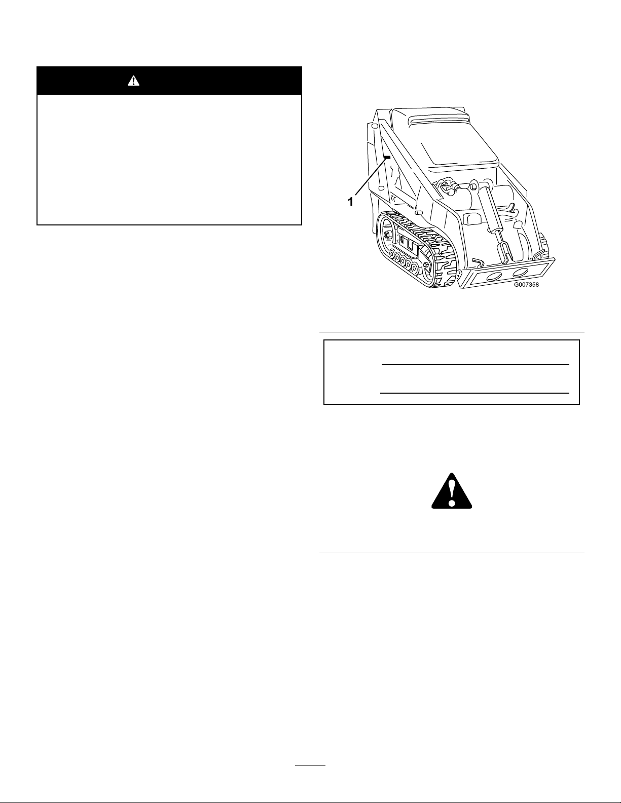
yourproductready.Figure1identiesthelocationofthe
modelandserialnumbersontheproduct.Writethenumbers
inthespaceprovided.
Figure1
1.Modelandserialnumberlocation
Important:ItisaviolationofCaliforniaPublic
ResourceCodeSection4442touseoroperatetheengine
onanyforest-covered,brush-covered,orgrass-covered
landwithoutasparkarrestermufermaintainedin
workingorder,ortheengineconstricted,equipped,and
maintainedforthepreventionofre.Otherstatesor
federalareasmayhavesimilarlaws.
Theenclosed
Engine Owner's Man ual
issuppliedfor
informationregardingtheUSEnvironmentalProtection
Agency(EPA)andtheCaliforniaEmissionControl
Regulationofemissionsystems,maintenance,and
warranty.Replacementsmaybeorderedthroughthe
enginemanufacturer.
Introduction
Thismachineisacompacttoolcarrierintendedforusein
variousearthandmaterialsmovingactivitiesforlandscaping
andconstructionwork.Itisdesignedtooperateawidevariety
ofattachmentseachofwhichperformaspecializedfunction.
ModelNo.
SerialNo.
Thismanualidentiespotentialhazardsandhassafety
messagesidentiedbythesafety-alertsymbol(Figure2),
whichsignalsahazardthatmaycauseseriousinjuryordeath
ifyoudonotfollowtherecommendedprecautions.
Figure2
1.Safety-alertsymbol
Thismanualuses2wordstohighlightinformation.
Importantcallsattentiontospecialmechanicalinformation
andNoteemphasizesgeneralinformationworthyofspecial
attention.
Readthisinformationcarefullytolearnhowtooperateand
maintainyourproductproperlyandtoavoidinjuryand
productdamage.Youareresponsibleforoperatingthe
productproperlyandsafely.
YoumaycontactTorodirectlyatwww .Toro.comforproduct
safetyandoperationtrainingmaterials,accessoryinformation,
helpndingadealer,ortoregisteryourproduct.
©2016—TheToro®Company
8111LyndaleAvenueSouth
Bloomington,MN55420
Contactusatwww.Toro.com.
2
PrintedintheUSA
AllRightsReserved
Page 3

Contents
Safety...........................................................................4
SafeOperatingPractices...........................................4
SoundPressureLevel...............................................6
SoundPower..........................................................6
VibrationLevel.......................................................6
StabilityData..........................................................7
SlopeIndicator.......................................................8
SafetyandInstructionalDecals.................................9
ProductOverview.........................................................13
Controls...............................................................13
Specications........................................................16
Attachments/Accessories........................................16
Operation....................................................................17
AddingFuel...........................................................17
FillingtheFuelTank...............................................17
CheckingtheEngine-OilLevel.................................18
CheckingtheHydraulicFluidLevel...........................19
Checking,Adding,andBleedingtheEngine
Coolant.............................................................20
BleedingtheFuelSystem.........................................21
StartingandShuttingOfftheEngine.........................21
StoppingtheTractionUnit......................................22
MovingaNon-FunctioningTractionUnit..................22
UsingtheCylinderLock..........................................22
UsingAttachments.................................................23
SecuringtheTractionUnitforTransport....................25
LiftingtheTractionUnit..........................................25
LoadingtheMachine..............................................25
Maintenance.................................................................27
RecommendedMaintenanceSchedule(s)......................27
PremaintenanceProcedures........................................28
OpeningtheHood.................................................28
ClosingtheHood...................................................28
OpeningtheRearAccessCover................................29
ClosingtheRearAccessCover.................................29
RemovingtheSideScreens......................................29
InstallingtheSideScreens........................................29
Lubrication...............................................................30
GreasingtheTractionUnit......................................30
EngineMaintenance..................................................30
ServicingtheAirCleaner.........................................30
ServicingtheEngineOil..........................................31
FuelSystemMaintenance...........................................33
CheckingtheFuelLinesandConnections..................33
DrainingtheFuelFilter/WaterSeparator...................33
ReplacingtheFuelFilterCanisterandIn-line
Filter.................................................................34
DrainingtheFuelTank...........................................34
ElectricalSystemMaintenance....................................34
ServicingtheBattery...............................................34
DriveSystemMaintenance.........................................37
ServicingtheTracks................................................37
CoolingSystemMaintenance......................................40
ServicingtheCoolingSystem...................................40
BeltMaintenance......................................................41
CheckingtheConditionoftheHydraulicPump
Belt...................................................................41
CheckingtheAlternator/FanBeltTension.................41
ControlsSystemMaintenance.....................................41
AdjustingtheTractionControlAlignment.................41
AdjustingtheTractionControlNeutral
Position.............................................................42
AdjustingtheTrackingoftheTractionControl,
FullForwardPosition..........................................43
HydraulicSystemMaintenance....................................43
ReplacingtheHydraulicFilter..................................43
ChangingtheHydraulicFluid...................................44
CheckingtheHydraulicLines...................................45
Cleaning...................................................................46
RemovingDebrisfromtheTractionUnit...................46
CleaningtheChassis...............................................46
Storage........................................................................46
Troubleshooting...........................................................47
Schematics...................................................................51
3
Page 4

Safety
Improperuseormaintenancebytheoperatororowner
canresultininjury.Toreducethepotentialforinjury,
complywiththesesafetyinstructionsandalways
payattentiontothesafety-alertsymbol,which
means:
instruction.Failuretocomplywiththeinstructionmay
resultinpersonalinjuryordeath.
Caution
,
W ar ning
,or
Danger
—personalsafety
•Wearappropriateclothingincludingsafetyglasses,long
pants,safetyshoes,andhearingprotection.Tiebacklong
hair.Donotwearjewelry.
•Inspecttheareawheretheequipmentistobeusedand
removeallobjectssuchasrocks,toys,andwirewhichcan
bethrownbythemachine.
•Useextracarewhenhandlingfuels.Theyareammable
andvaporsareexplosive.
–Useonlyanapprovedcontainer
SafeOperatingPractices
Thisproductiscapableofamputatinghandsandfeet.Always
followallsafetyinstructionstoavoidseriousinjuryordeath.
WARNING
Engineexhaustcontainscarbonmonoxide,an
odorless,deadlypoisonthatcankillyou.
Donotruntheengineindoorsorinanenclosed
area.
Training
•ReadtheOperator'sManualandothertrainingmaterial.If
theoperator(s)ormechanic(s)cannotreadEnglish,itis
theowner'sresponsibilitytoexplainthismaterialtothem.
•Becomefamiliarwiththesafeoperationoftheequipment,
operatorcontrols,andsafetysigns.
•Alloperatorsandmechanicsshouldbetrained.The
ownerisresponsiblefortrainingtheusers.
•Neverletchildrenoruntrainedpeopleoperateorservice
theequipment.Localregulationsmayrestricttheageof
theoperator.
•Theowner/usercanpreventandisresponsiblefor
accidentsorinjuriesoccurringtohimselforherself,other
peopleorproperty.
Preparation
–Neverremovethefuelcaporaddfuelwiththeengine
running.Allowtheenginetocoolbeforerefueling.
Donotsmoke.
–Neverrefuelordrainthemachineindoors.
•Checkthattheoperator'spresencecontrols,safety
switches,andshieldsareattachedandfunctioning
properly.Donotoperateunlesstheyarefunctioning
properly.
Operation
•Onlyoperateingoodlight,keepingawayfromholesand
hiddenhazards.
•Besurealldrivesareinneutralandparkingbrakeis
engagedbeforestartingtheengine.Onlystarttheengine
fromtheoperator'sposition.
•Slowdownanduseextracareonhillsides.Besureto
travelintherecommendeddirectiononhillsides.Turf
conditionscanaffectthemachine'sstability .
•Slowdownandusecautionwhenmakingturnsandwhen
changingdirectionsonslopes.
•Donotchangetheenginegovernorsettingoroverspeed
theengine.
•Stoponlevelground,lowerimplements,disengagethe
auxiliaryhydraulics,engageparkingbrake,shutoffthe
engine,andremovethekeybeforeleavingtheoperator's
positionforanyreason.
•Keephandsandfeetawayfrommovingattachments.
DANGER
Theremaybeburiedpower,gas,and/ortelephone
linesintheworkarea.Shockorexplosionmay
occurifyoudigintothem.
Havethepropertyorworkareamarkedforburied
linesanddonotdiginmarkedareas.Contactyour
localmarkingserviceorutilitycompanytohavethe
propertymarked(forexample,inAustralia,call1100
forthenationwidemarkingservice).
•Evaluatetheterraintodeterminewhataccessoriesand
attachmentsareneededtoproperlyandsafelyperform
thejob.Useonlyaccessoriesandattachmentsapproved
bythemanufacturer.
•Lookbehindanddownbeforebackinguptobesureof
aclearpath.
•Nevercarrypassengersandkeeppetsandbystanders
away.
•Slowdownandusecautionwhenmakingturnsand
crossingroadsandsidewalks.
•Donotoperatethemachinewhileill,tired,orunderthe
inuenceofalcoholordrugs.
•Usecarewhenloadingorunloadingthemachineintoa
trailerortruck.
•Usecarewhenapproachingblindcorners,shrubs,trees,
orotherobjectsthatmayobscurevision.
•Readallattachmentmanuals.
4
Page 5

•Ensurethattheareaisclearofotherpeoplebefore
operatingthetractionunit.Stopthetractionunitif
anyoneentersthearea.
•Neverleavearunningtractionunitunattended.Always
lowertheloaderarms,shutofftheengine,settheparking
brake,andremovethekeybeforeleaving.
•Donotexceedtheratedoperatingcapacity,asthetraction
unitmaybecomeunstablewhichmayresultinlossof
control.
•Donotcarryaloadwiththearmsraised.Alwayscarry
loadsclosetotheground.
•Donotover-loadtheattachmentandalwayskeepthe
loadlevelwhenraisingtheloaderarms.Logs,boards,and
otheritemscouldrolldowntheloaderarms,injuringyou.
•Neverjerkthecontrols;useasteadymotion.
•Watchfortrafcwhenoperatingnearorcrossing
roadways.
•Donottouchpartswhichmaybehotfromoperation.
Allowthemtocoolbeforeattemptingtomaintain,adjust,
orservice.
•Checkforoverheadclearances(i.e.,branches,doorways,
electricalwires)beforedrivingunderanyobjectsanddo
notcontactthem.
•Ensurethatyouoperatethetractionunitinareaswhere
therearenoobstaclesincloseproximitytotheoperator.
Failuretomaintainadequatedistancefromtrees,walls,
andotherbarriersmayresultininjuryasthetractionunit
backsupduringoperationiftheoperatorisnotattentive
tothesurroundings.Onlyoperatetheunitinareaswhere
thereissufcientclearancefortheoperatortosafely
maneuvertheproduct.
•Beforedigging,havetheareamarkedforunderground
utilities,anddonotdiginmarkedareas.
•Locatethepinchpointareasmarkedonthetractionunit
andattachmentsandkeephandsandfeetawayfrom
theseareas.
•Beforeoperatingthetractionunitwithanattachment,
ensurethattheattachmentisproperlyinstalled.
•Lightningcancausesevereinjuryordeath.Iflightning
isseenorthunderisheardinthearea,donotoperate
themachine;seekshelter.
theheavyend,andafullbucketmakesthefrontofthe
tractionunittheheavyend.Mostotherattachmentsmake
thefrontoftractionunittheheavyend.
•Raisingtheloaderarmsonaslopeaffectsthestabilityof
themachine.Wheneverpossible,keeptheloaderarmsin
theloweredpositionwhenonslopes.
•Removinganattachmentonaslopemakestherearofthe
tractionunitheavy .RefertoStabilityData(page7),to
determinewhethertheattachmentcanbesafelyremoved
ontheslope.
•Removeobstaclessuchasrocks,treelimbs,etc.fromthe
workarea.Watchforholes,ruts,orbumps,asuneven
terraincouldoverturnthetractionunit.Tallgrasscan
hideobstacles.
•UseonlyT oro-approvedattachments.Attachmentscan
changethestabilityandtheoperatingcharacteristicsof
thetractionunit.Warrantymaybevoidedifusedwith
unapprovedattachments.
•Keepallmovementsonslopesslowandgradual.Donot
makesuddenchangesinspeedordirection.
•Avoidstartingorstoppingonaslope.Ifthetractionunit
losestraction,proceedslowly,straightdowntheslope.
•Avoidturningonslopes.Ifyoumustturn,turnslowly
andkeeptheheavyendofthetractionunituphill.
•Donotoperateneardrop-offs,ditches,orembankments.
Thetractionunitcouldsuddenlyturnoverifatrackgoes
overtheedgeofaclifforditch,orifanedgecavesin.
•Donotoperateonwetgrass.Reducedtractioncould
causesliding.
•Donotparkthetractionunitonahillsideorslope
withoutloweringtheattachmenttotheground,setting
theparkingbrake,andchockingthetracks.
MaintenanceandStorage
•Disengagetheauxiliaryhydraulics,lowertheattachment,
settheparkingbrake,shutofftheengine,andremove
thekey.W aitforallmovementtostopbeforeadjusting,
cleaning,orrepairing.
•Cleandebrisfromattachments,drives,mufers,and
enginetohelppreventres.Cleanupoilorfuelspills.
SlopeOperation
Slopesareamajorfactorrelatedtoloss-of-controland
tip-overaccidents,whichcanresultinsevereinjuryordeath.
Allslopesrequireextracaution.
•Donotoperatethetractionunitonhillsidesorslopes
exceedingtheanglesrecommendedinStabilityData(page
7),andthoseintheattachmentOperator'sManual.Seealso
theSlopeIndicator(page8).
•Operateupanddownslopeswiththeheavyendof
thetractionunituphill.Weightdistributionchanges.
Anemptybucketmakestherearofthetractionunit
•Lettheenginecoolbeforestoringanddonotstorenear
ame.
•Donotstorefuelnearamesordrainindoors.
•Parkthemachineonlevelground.Neverallowuntrained
personneltoservicethemachine.
•Usejackstandstosupportcomponentswhenrequired.
•Carefullyreleasepressurefromcomponentswithstored
energy.
•Disconnectthebatterybeforemakinganyrepairs.
Disconnectthenegativeterminalrstandthepositive
last.Connectpositiverstandnegativelast.
5
Page 6

•Keephandsandfeetawayfrommovingparts.Ifpossible,
donotmakeadjustmentswiththeenginerunning.
•Chargebatteriesinanopen,well-ventilatedarea,away
fromsparkandames.Unplugthechargerbefore
connectingordisconnectingitfromthebattery.Wear
protectiveclothinganduseinsulatedtools.
•Keepallpartsingoodworkingconditionandallhardware
tightened.Replaceallwornordamageddecals.
SoundPressureLevel
SoundPressureLevelThisunithasasoundpressurelevelat
theoperator’ searof93dBA,whichincludesanUncertainty
Value(K)of1dBA.
Soundpressurelevelwasdeterminedaccordingtothe
proceduresoutlinedinEN11201.
•Ifanymaintenanceorrepairrequirestheloaderarmsto
beintheraisedposition,securethearmsintheraised
positionwiththehydrauliccylinderlocks.
•Keepnutsandboltstight.Keepequipmentingood
condition.
•Nevertamperwithsafetydevices.
•Keepthetractionunitfreeofgrass,leaves,orotherdebris
buildup.Cleanupoilorfuelspills.Allowthetraction
unittocoolbeforestoring.
•Useextracarewhenhandlingfuels.Theyareammable
andvaporsareexplosive.
–Useonlyanapprovedcontainer.
–Neverremovethefuelcaporaddfuelwhenthe
engineisrunning.Allowtheenginetocoolbefore
refueling.Donotsmoke.
–Neverrefuelthetractionunitindoors.
–Neverstorethetractionunitorfuelcontainerinside
wherethereisanopename,suchasnearawater
heaterorfurnace.
–Neverllacontainerwhileitisinsideavehicle,trunk,
pickupbed,oranysurfaceotherthantheground.
SoundPower
Thisunithasaguaranteedsoundpowerlevelof101dBA,
whichincludesanUncertaintyV alue(K)of1dBA.
Thesoundpowerlevelwasdeterminedaccordingtothe
proceduresoutlinedinISO6395.
VibrationLevel
Measuredvibrationlevelforrighthand=1.5m/s
Measuredvibrationlevelforlefthand=1.3m/s
UncertaintyValue(K)=0.8m/s
Measuredvaluesweredeterminedaccordingtotheprocedures
outlinedinENISO20643.
2
2
2
–Keepcontainernozzleincontactwiththetankduring
lling.
•Stopandinspecttheequipmentifyoustrikeanobject.
Makeanynecessaryrepairsbeforestarting.
•UseonlygenuineT ororeplacementpartstoensurethat
originalstandardsaremaintained.
•Batteryacidispoisonousandcancauseburns.Avoid
contactwithskin,eyes,andclothing.Protectyourface,
eyes,andclothingwhenworkingwithabattery.
•Batterygasescanexplode.Keepcigarettes,sparks,and
amesawayfromthebattery.
•Keepyourbodyandhandsawayfrompinholeleaks
ornozzlesthatejecthigh-pressurehydraulicuid.Use
cardboardorpapertondhydraulicleaks;neveruse
yourhands.Hydraulicuidescapingunderpressurecan
penetrateskinandcauseinjuryrequiringsurgerywithin
afewhoursbyaqualiedsurgeonotherwisegangrene
mayresult.
6
Page 7
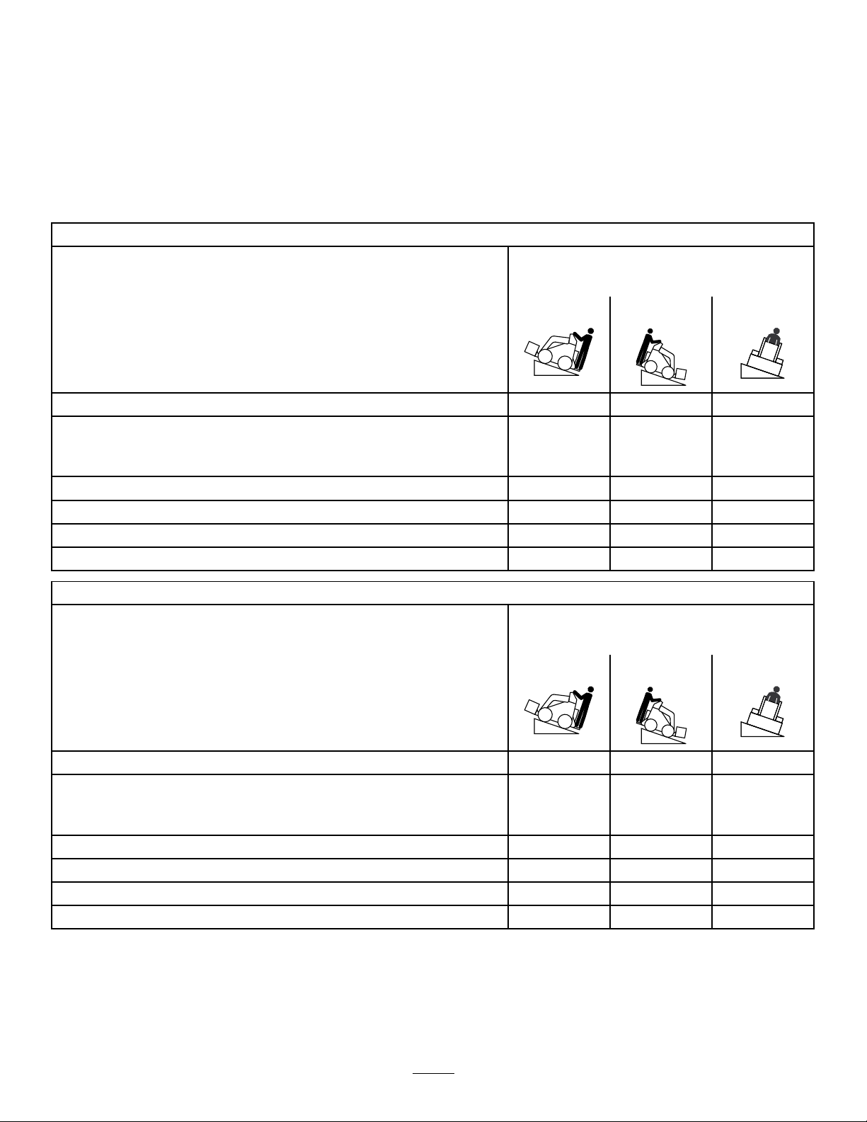
StabilityData
Thefollowingtableslistthemaximumsloperecommendedforthetractionunitinthepositionslistedinthetables.Slopesover
thelisteddegreemaycausethetractionunittobecomeunstable.Thedatainthetablesassumethattheloaderarmsarefully
lowered;raisedarmsmayaffectthestability.
Ineachattachmentmanualisasetof3stabilityratings,oneforeachhillposition.Todeterminethemaximumslopeyoucan
traversewiththeattachmentinstalled,ndthedegreeofslopethatcorrespondstothestabilityratingsoftheattachment.
Example:IftheattachmentinstalledonaTXmodel22323tractionunithasaFrontUphillratingofB,aRearUphillratingof
D,andaSideUphillratingofC,thenyoucoulddriveforwardupa19°slope,rearwardupa12°slope,orsidewaysona14°
slope,aslistedinthefollowingtable.
Model22323
MaximumRecommendedSlopewhen
Operatingwith:
FrontUphillRearUphill
Conguration
Tractionunitwithoutattachment
Tractionunitwithanattachmentratedwithoneofthefollowingstabilityratings
foreachslopeposition:*
A
B
C16°15°14°
D
E
Model22324
11°21°19°
25°25°20°
19°19°18°
10°12°9°
5°5°5°
MaximumRecommendedSlopewhen
Operatingwith:
FrontUphillRearUphill
SideUphill
SideUphill
Conguration
Tractionunitwithoutattachment
Tractionunitwithanattachmentratedwithoneofthefollowingstabilityratings
foreachslopeposition:*
A
B
C18°16°14°
D
E
12°19°21°
25°25°23°
22°22°20°
10°10°10°
5°5°5°
7
Page 8
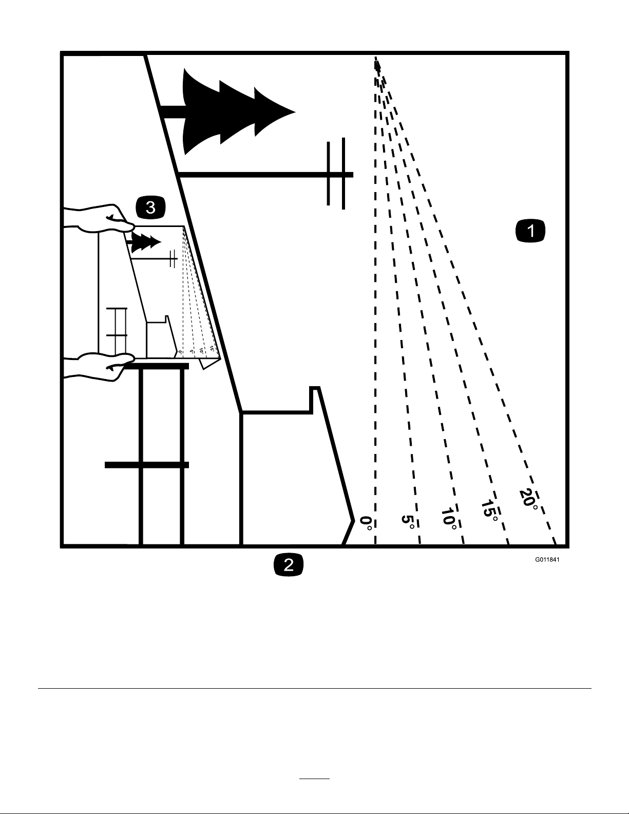
SlopeIndicator
G011841
Figure3
Thispagemaybecopiedforpersonaluse.
1.Todeterminethemaximumslopeyoucansafelyoperatethemachineon,refertotheStabilityDatasection.Usetheslope
indicatortodeterminethedegreeofslopeofhillsbeforeoperating.Donotoperatethismachineonaslopegreaterthanthat
speciedintheStabilityDatasection.Foldalongtheappropriatelinetomatchtherecommendedslope.
2.Alignthisedgewithaverticalsurface,atree,building,fencepole,etc.
3.Exampleofhowtocompareslopewithfoldededge
8
Page 9
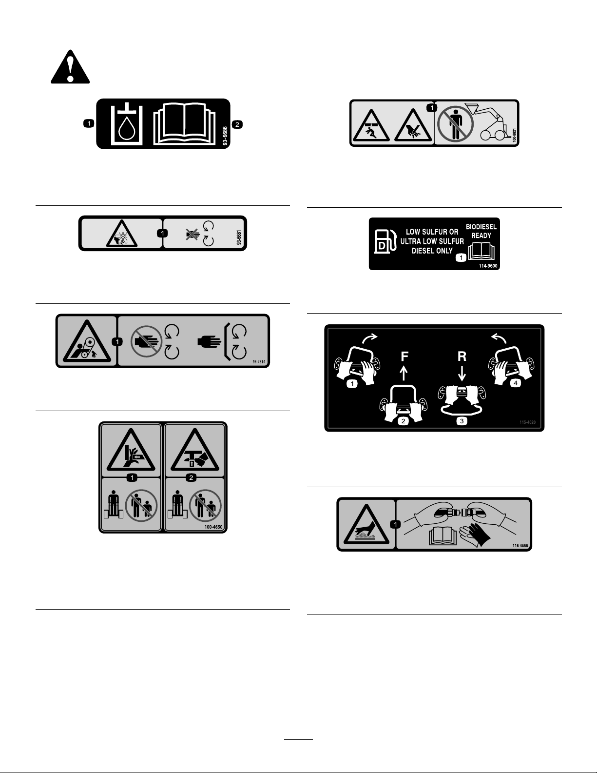
SafetyandInstructionalDecals
Safetydecalsandinstructionsareeasilyvisibletotheoperatorandarelocatednearanyareaofpotential
danger.Replaceanydecalthatisdamagedorlost.
93-6686
1.Hydraulicuid
2.ReadtheOperator'sManual.
93-6681
1.Cutting/dismemberment—hazard,fan-stayawayfrom
movingparts.
93-7814
1.Entanglementhazard,belt—stayawayfrommovingparts.
100-8821
1.Crushinghazardandcuttinghazardofhand—stayasafe
distanceawayfromthefrontofthetractionunitwhenthe
loaderarmsareraised.
114-9600
1.ReadtheOperator'sManual.
100-4650
1.Crushinghazardofhand—keepbystandersasafedistance
awayfromthemachine.
2.Crushinghazardoffoot—keepbystandersasafedistance
awayfromthemachine.
115-4020
1.Turnright3.Reverse
2.Forward
4.Turnleft
115-4855
1.Hotsurface/burnhazard—wearprotectivegloveswhen
handlingthehydrauliccouplersandreadtheOperator's
Manualforinformationonhandlinghydrauliccomponents.
9
Page 10
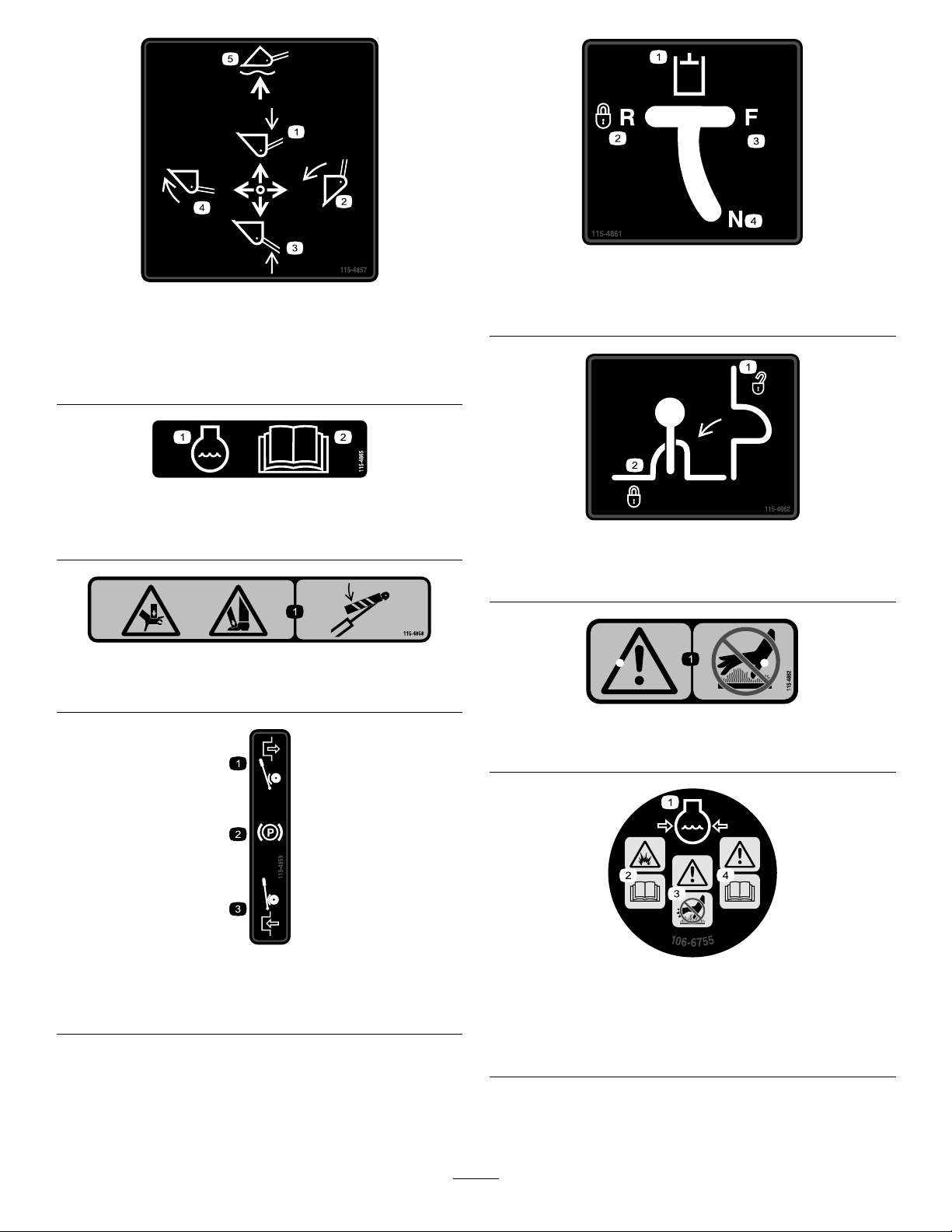
115-4861
115-4857
1.Lowertheloaderarms.
2.Dumpthebucket.5.Floatthebucketonthe
3.Raisetheloaderarms.
4.Curlthebucket.
ground.
115-4865
1.Enginecoolant
2.ReadtheOperator's
Manual.
115-4858
1.Crushinghazardofhandsorfeet—installthecylinderlock.
1.Auxiliaryhydraulics3.Forward
2.Lockedreverse(detent)4.Neutral(off)
115-4862
1.Loader-valve
lock—unlocked
2.Loader-valvelock—locked
115-4882
1.Disengaged3.Engaged
2.Parkingbrake
1.Warning—stayasafedistanceawayfromthehotsurfaces.
115-4859
106-6755
1.Enginecoolantunder
pressure.
2.Explosionhazard—read
theOperator'sManual.
3.Warning—donottouchthe
hotsurface.
4.Warning—readthe
Operator'sManual.
10
Page 11
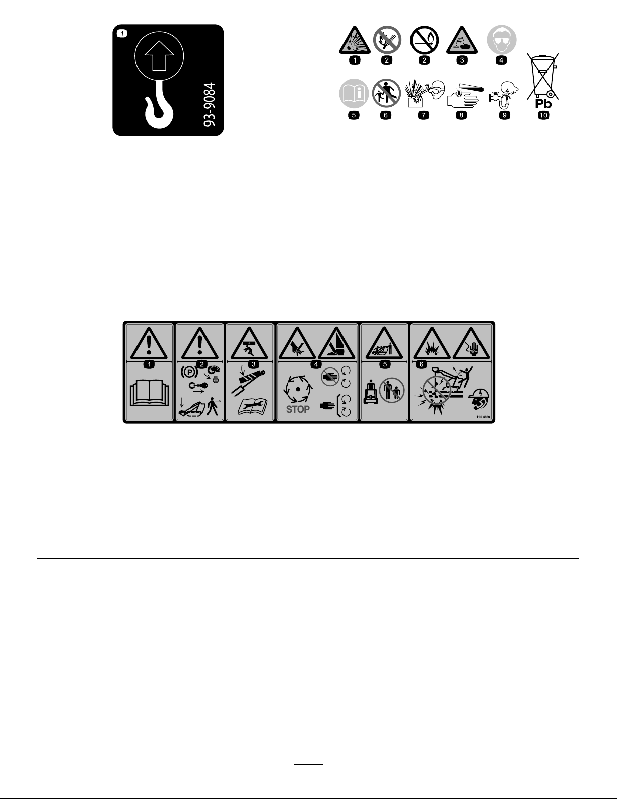
1.Liftpoint
93-9084
2.Tie-downpoint
BatterySymbols
Someorallofthesesymbolsareonyourbattery .
1.Explosionhazard
2.Nore,opename,or
smoking
3.Causticliquid/chemical
burnhazard
4.Weareyeprotection.9.Flusheyesimmediately
5.ReadtheOperator's
Manual.
6.Keepbystandersasafe
distancefromthebattery.
7.Weareyeprotection;
explosivegasescan
causeblindnessandother
injuries.
8.Batteryacidcancause
blindnessorsevereburns.
withwaterandgetmedical
helpfast.
10.Containslead;donot
discard.
115-4860
1.Warning—readtheOperator'sManual.
2.Warning—settheparkingbrake,shutofftheengine,removetheignitionkeyandlowertheloaderarmsbeforeleavingthemachine.
3.Crushinghazard—installthecylinderlockandreadtheinstructionsbeforeservicingorperformingmaintenance.
4.Cuttinghazardofhandsorfeet—waitforallmovingpartstostop;stayawayfrommovingparts;keepallguardsandshieldsin
place.
5.Crushing/dismembermenthazardofbystanders—keepbystandersasafedistanceawayfromthemachine.
6.Explosionandelectricshockhazard—donotdiginareaswithburiedgasorelectricallines;contactlocalpowerorganizations
beforedigging.
11
Page 12
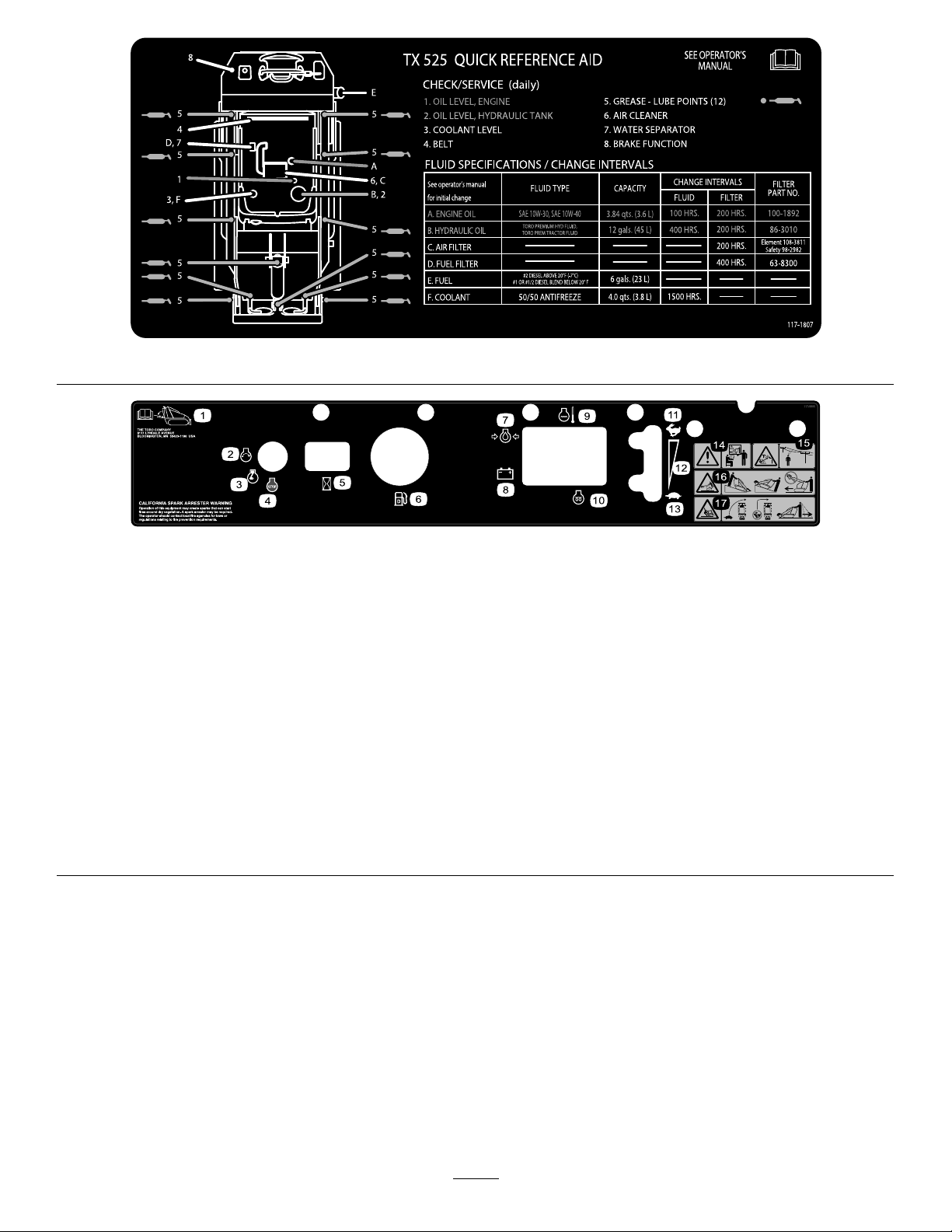
117-1807
117-9905
1.Operator'sManuallocation
2.Engine—start7.Engineoilpressure
3.Engine—run8.Battery
4.Engine—stop9.Enginetemperature14.Warning—donotoperate
5.Hourmeter
6.Fuelgauge—diesel1 1.Fast16.Tippinghazard—movethe
12.Continuousvariablesetting
13.Slow
thismachineunlessyou
aretrained.
10.Glowplug
15.Electricshockhazard,
overheadpowerlines—stay
awayfromoverheadpower
lines.
tractionunitwiththeheavy
enduphill;carryloadslow;
neverjerkthecontrols;use
asteady,evenmotion.
17.Tippinghazard—slowthe
tractionunitwhenturning,
donottravelfastwhen
turning,lookbehindand
downwhenreversing.
12
Page 13
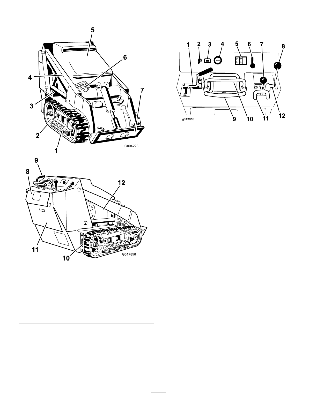
ProductOverview
12
G017858
1
2
3
4
5
6 7
8
12
11
109
g013016
Controls
Becomefamiliarwithallthecontrols(Figure5)beforeyou
starttheengineandoperatethetractionunit.
Figure5
Figure4
1.Roadwheels7.Mountplate
2.Track
3.Liftcylinder9.Controlpanel
4.Loaderarms
5.Hood11.Rearaccesscover
6.Auxiliary-hydraulic
couplers
8.Reversesafetyplate
10.Tie-down/liftloop
12.Sidepanelscreen
1.Auxiliary-hydraulicslever
2.Keyswitch8.Parking-brakelever
3.Hourmeter9.Tractioncontrol
4.Fuelgauge
5.Indicatorlightsandglow
plugswitch
6.Throttlelever12.Loader-valvelock
7.Loaderarm/attachmenttilt
lever
10.Referencebar
11.Loader-control-reference
bar
KeySwitch
Thekeyswitch,usedtostartandshutofftheengine,has3
positions:OFF,RUN,andSTART.
•Tostarttheengine,rotatethekeytotheRUNposition,
theglow-pluglightcomeson.Whentheglow-pluglight
turnsoff,turnthekeytotheSTARTposition.Release
thekeywhenenginestartsanditmovesautomatically
totheRUNposition.
•Toshutofftheengine,rotatethekeytotheOFFposition.
ThrottleLever
Movethecontrolforwardtoincreasetheenginespeedand
rearwardtodecreasespeed.
ReferenceBar
Whendrivingthetractionunit,usethereferencebaras
ahandleandaleveragepointforcontrollingthetraction
controlandtheauxiliary-hydraulicslever.Toensuresmooth,
controlledoperation,donottakebothhandsoffthereference
barwhileoperatingthetractionunit.
13
Page 14
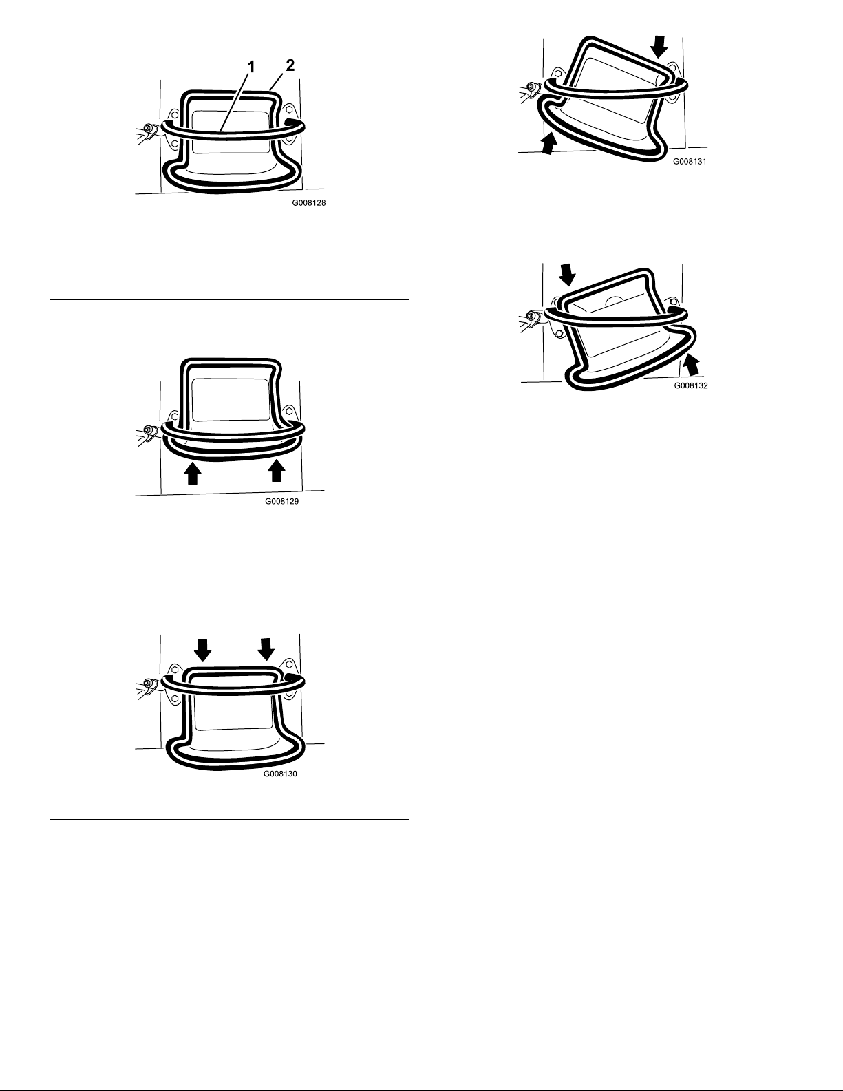
TractionControl
G008131
G008132
Figure9
Figure6
1.Referencebar(doesnotmovetogiveyouareferencepoint
andaxedhandletoholdwhileoperatingthetractionunit)
2.Tractioncontrol(movestocontrolthemachine)
•Tomoveforward,movethetractioncontrolforward
(Figure7).
Figure7
•Tomoverearward,movethetractioncontrolrearward
(Figure8).Whenreversing,lookbehindfor
obstructionsandkeepyourhandsonthereference
bar.
•Toturnleft,rotatethetractioncontrolcounterclockwise
(Figure10).
Figure10
•Tostop,releasethetractioncontrol(Figure6).
Note:Thefartheryoumovethetractioncontrolinany
direction,thefasterthemachinemovesinthatdirection.
LoaderArm/AttachmentTiltLever
Totilttheattachmentforward,slowlymovethelevertothe
right(Figure11).
Totilttheattachmentrearward,slowlymovethelevertothe
left(Figure11).
Figure8
•Toturnright,rotatethetractioncontrolclockwise(Figure
9).
Tolowertheloaderarms,slowlymovetheleverforward
(Figure11).
Toraisetheloaderarms,slowlymovetheleverrearward
(Figure11).
Youcanalsopushtheleverfullyforwardintoadetent
position(Figure11)toreleasetheloaderarmssothatthe
attachmentrestsontheground.Thisallowsattachmentssuch
asthelevelerandthehydraulicbladetofollowthecontours
oftheground(i.e.,oat)whengrading.
14
Page 15
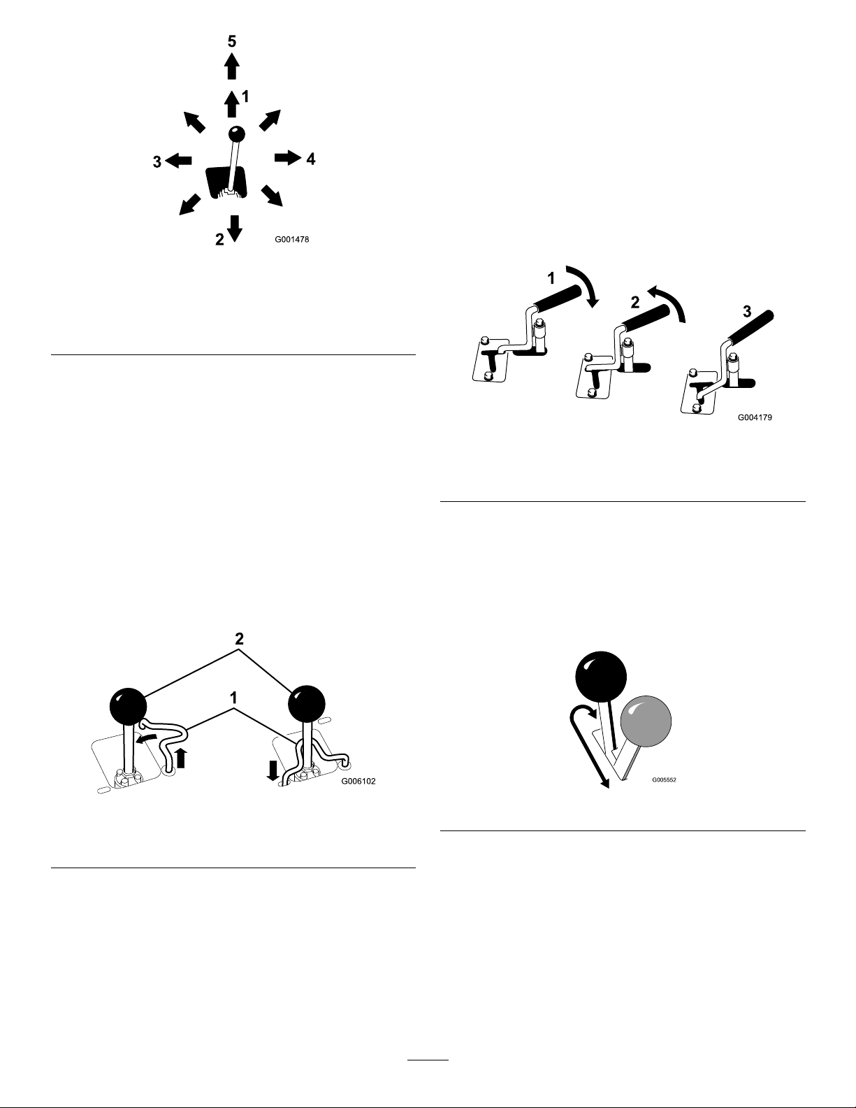
Figure11
Auxiliary-HydraulicsLever
Tooperateahydraulicattachmentintheforwarddirection,
rotatetheauxiliary-hydraulicsleverrearwardandpullitdown
tothereferencebar(Figure13,number1).
Tooperateahydraulicattachmentinreversedirection,rotate
thehydraulicsleverrearward,thenmoveitleftintotheupper
slot(Figure13,number2).
Ifyoureleasetheleverwhileintheforwardposition,the
leverautomaticallyreturnstotheneutralposition(Figure13,
number3).Ifitisinthereverseposition,itremainsthere
untilyoupullitoutoftheslot.
1.Lowertheloaderarms
2.Raisetheloaderarms
3.Tilttheattachment
rearward
4.Tilttheattachmentforward
5.Detent(Float)position
Bymovingthelevertoanintermediateposition(suchas,
forwardandleft),youcanmovetheloaderarmsandtiltthe
attachmentatthesametime.
Loader-ValveLock
Theloader-valvelocksecurestheloaderarm/attachment
tiltleversothatyoucannotpushitforward.Thishelpsto
ensurethatnooneaccidentallylowerstheloaderarmsduring
maintenance.Securetheloaderarmswiththelockanytime
youneedtostopthemachinewiththeloaderarmsraised.
Tosetthelock,liftuponitsothatitclearstheholeinthe
controlpanelandswingittotheleftinfrontoftheloaderarm
lever,pushingitdownintothelockedposition(Figure12).
Figure13
1.Forward-owhydraulics
2.Reverse-owhydraulics
3.Neutral
Parking-BrakeLever
Tosettheparkingbrake,pushthebrakeleverforwardandto
theleftandthenpullitrearward(Figure14).
Note:Thetractionunitmayrollslightlybeforethebrakes
engageinthedrivesprocket.
Figure12
1.Loader-valvelock
2.Loaderarm/attachmenttilt
lever
Loader-Control-ReferenceBar
Theloader-control-referencebarhelpsstabilizeyourhand
whileoperatingtheloaderarm/attachmenttiltlever.
Figure14
Toreleasethebrake,pushtheleverforwardandthenright,
intothenotch.
FuelGauge
Thisgaugemeasurestheamountoffuelinthefueltank.
15
Page 16
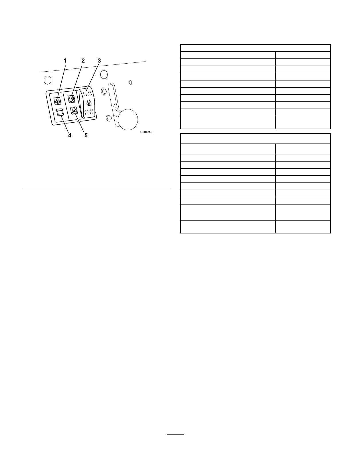
Engine-OilPressureLight
G004350
123
45
Specications
Iftheengine-oilpressuregetstoolow ,thislightilluminates
andanaudiblealarmsounds.Ifthishappens,shutoffthe
engineimmediatelyandchecktheoil.Iflow,addoiland/or
lookforpossibleleaks.
Figure15
1.Engine-oilpressurelight4.Batterychargeindicator
2.Engine-coolant
temperaturelight
3.Glow-plugswitch
light
5.Glow-pluglight
BatteryChargeIndicatorLight
Ifthebatterychargebecomestoolow,thislightilluminates
andanaudiblealarmsounds.Ifthishappens,shutoffthe
engineandchargeorreplacethebattery.Checkthetension
ofthealternatorbelt;refertoyourengineowner’smanual.
Note:Specicationsanddesignaresubjecttochange
withoutnotice.
Model22323
Width
Length
Height
Weight
Operatingcapacity251kg(553lb)
Tippingcapacity
Wheelbase
Dumpheight(withnarrowbucket)119cm(47inches)
Reach—fullyraised(withnarrowbucket)55cm(22inches)
Heighttohingepin(narrowbucketin
highestposition)
Model22324
Width
Length
Height
Weight
Operatingcapacity251kg(553lb)
Tippingcapacity
Wheelbase
Dumpheight(withnarrowbucket)119cm(47inches)
Reach—fullyraised(withnarrowbucket)55cm(22inches)
Heighttohingepin(narrowbucketin
highestposition)
86cm(34inches)
180cm(71inches)
117cm(46inches)
864kg(1904lb)
717kg(1,580lb)
79cm(31.2inches)
168cm(66inches)
104cm(41inches)
180cm(71inches)
109cm(43inches)
913kg(2,013lb)
717kg(1580lb)
79cm(31.2inches)
168cm(66inches)
EngineCoolantTemperatureLight
Iftheenginecoolantgetstoohot,thislightilluminatesand
anaudiblealarmsounds.Ifthishappens,shutofftheengine
andallowthetractionunittocool.Checkthecoolantlevel
whentheenginehasfullycooled.
Glow-PlugLight
Illuminateswhiletheglowplugsarechargedandwarming
theengine.
Glow-PlugSwitch
Pressandholdthisswitchfor10secondstoactivatetheglow
plugsbeforestartingtheengine.
HourMeter
Thehourmeterdisplaysthenumberofhoursofoperation
thathavebeenloggedonthetractionunit.
Attachments/Accessories
AselectionofToroapprovedattachmentsandaccessoriesis
availableforusewiththemachinetoenhanceandexpand
itscapabilities.ContactyourAuthorizedServiceDealeror
Distributororgotowww .Toro.comforalistofallapproved
attachmentsandaccessories.
Important:UseonlyToroapprovedattachments.
Otherattachmentsmaycreateanunsafeoperating
environmentordamagethetractionunit.
16
Page 17

Operation
•Monitorseals,hoses,gasketsincontactwithfuelasthey
maybedegradedovertime.
Note:Determinetheleftandrightsidesofthemachine
fromthenormaloperatingposition.
Important:Beforeoperating,checkthefuelandoil
level,andremovedebrisfromthetractionunit.Also,
ensurethattheareaisclearofpeopleanddebris.Y ou
shouldalsoknowandhavemarkedthelocationsofall
utilitylines.
AddingFuel
Useonlyclean,freshdieselfuelorbiodieselfuelswithlow
(<500ppm)orultralow(<15ppm)sulfurcontent.The
minimumcetaneratingshouldbe40.Purchasefuelin
quantitiesthatcanbeusedwithin180daystoensurefuel
freshness.
Fueltankcapacity:22L(5.85USgallons)
Usesummer-gradedieselfuel(No.2-D)attemperatures
above-7°C(20°F)andwinter-gradedieselfuel(No.1-D
orNo.1-D/2-Dblend)belowthattemperature.Useof
winter-gradefuelatlowertemperaturesprovideslowerash
pointandcoldowcharacteristicswhicheasesstartingand
reducesfuellterplugging.
Usingsummer-gradefuelabove-7°C(20°F)contributes
towardlongerfuelpumplifeandincreasedpowercompared
towinter-gradefuel.
Important:Donotusekeroseneorgasolineinsteadof
dieselfuel.Failuretoobservethiscautionwilldamage
theengine.
•Fuellterpluggingmaybeexpectedforatimeafter
convertingtobiodieselblendsd.
•Contactyourdistributorifyouwishformoreinformation
onbiodiesel.
FillingtheFuelTank
DANGER
Incertainconditions,fuelisextremelyammable
andhighlyexplosive.Areorexplosionfromfuel
canburnyouandothersandcandamageproperty.
•Fillthefueltankoutdoors,inanopenarea,when
theengineiscold.Wipeupanyfuelthatspills.
•Neverllthefueltankinsideanenclosedtrailer.
•Neversmokewhenhandlingfuel,andstayaway
fromanopenameorwherefuelfumesmaybe
ignitedbyaspark.
•Storefuelinanapprovedcontainerandkeepit
outofthereachofchildren.Neverbuymore
thana30-daysupplyoffuel.
•Donotoperatewithouttheentireexhaust
systeminplaceandinproperworkingcondition.
DANGER
WARNING
Fuelisharmfulorfatalifswallowed.Long-term
exposuretovaporscancauseseriousinjuryand
illness.
•Avoidprolongedbreathingofvapors.
•Keepfaceawayfromnozzleandfueltankor
conditioneropening.
•Keepfuelawayfromeyesandskin.
BiodieselReady
Thismachinecanalsouseabiodieselblendedfuelofup
toB20(20%biodiesel,80%petrodiesel).Thepetrodiesel
portionshouldbeloworultralowsulfur.Observethe
followingprecautions:
•Thebiodieselportionofthefuelmustmeetspecication
ASTMD6751orEN14214.
•TheblendedfuelcompositionshouldmeetASTMD975
orEN590.
•Paintedsurfacesmaybedamagedbybiodieselblends.
•UseB5(biodieselcontentof5%)orlesserblendsincold
weather.
Incertainconditionsduringfueling,static
electricitycanbereleasedcausingasparkwhich
canignitethefuelvapors.Areorexplosionfrom
fuelcanburnyouandothersandcandamage
property.
•Alwaysplacefuelcontainersonthegroundaway
fromyourvehiclebeforelling.
•Donotllfuelcontainersinsideavehicleoron
atruckortrailerbedbecauseinteriorcarpets
orplastictruckbedlinersmayinsulatethe
containerandslowthelossofanystaticcharge.
•Whenpractical,removeequipmentfromthe
truckortrailerandrefueltheequipmentwithits
wheelsontheground.
•Ifthisisnotpossible,thenrefuelsuchequipment
onatruckortrailerfromaportablecontainer,
ratherthanfromafuel-dispensernozzle.
•Ifyoumustuseafuel-dispensernozzle,keepthe
nozzleincontactwiththerimofthefueltank
orcontaineropeningatalltimesuntilfuelingis
complete.
17
Page 18
1.Removethefuel-tankcap(Figure16).
Figure16
1.Fuel-tankcap
2.Fillthetanktoabout2.5cm(1inch)belowthetopof
thetank,notthellerneck,withdieselfuel.
CheckingtheEngine-OilLevel
ServiceInterval:Beforeeachuseordaily
1.Parkthetractionunitonalevelsurface,lowerthe
loaderarms,andshutofftheengine.
2.Removethekeyandallowtheenginetocool.
3.Openthehood.
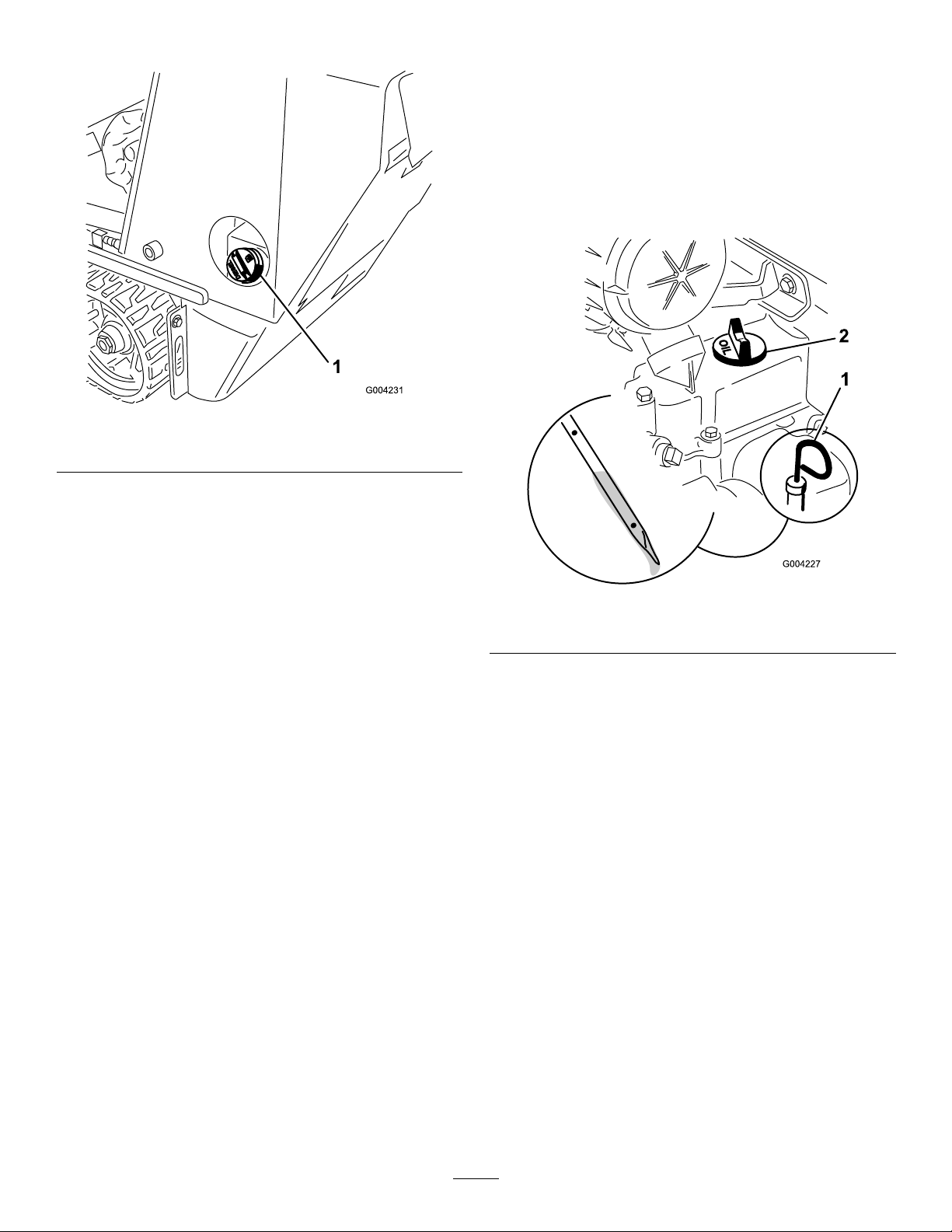
4.Cleanaroundtheoildipstick(Figure17).
3.Installthefuel-tankcap.
Figure17
1.Oildipstick2.Oil-llercap
5.Pulloutthedipstickandwipethemetalendclean
(Figure17).
6.Slidethedipstickfullyintothedipsticktube(Figure17).
7.Pullthedipstickoutandlookatthemetalend.
8.Iftheoillevelislow(belowthebottomhole),clean
aroundtheoil-llercapandremovethecap(Figure17).
9.Slowlypouronlyenoughoilintothevalvecoverto
raisetheleveltothetopholeonthedipstick.
Important:Donotoverllthecrankcasewithoil
becauseitmaydamagetheengine.
10.Replacethellercapanddipstick.
11.Closethehood.
18
Page 19
CheckingtheHydraulicFluid Level
ServiceInterval:Every25hours
HydraulicTankCapacity:45L(12USgallons)
RefertoChangingtheHydraulicFluid(page44)forhydraulic
uidspecications.
Important:Alwaysusethecorrecthydraulicuid.
Unspecieduidswilldamagethehydraulicsystem.
1.Removetheattachment,ifoneisinstalled;referto
RemovinganAttachment(page25).
2.Parkthetractionunitonalevelsurface,lowerthe
loaderarms,andfullyretractthetiltcylinder.
3.Shutofftheengine,removethekey,andallowthe
enginetocool.
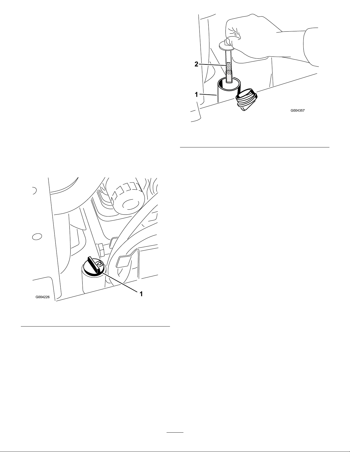
Figure19
1.Fillerneck2.Dipstick
4.Openthehood.
5.Cleantheareaaroundthellerneckofthehydraulic
tank(Figure18).
Figure18
1.Hydraulicller-neckcap
7.Ifthelevelislow ,addenoughuidtoraiseittothe
properlevel.
8.Installthecaponthellerneck.
9.Closethehood.
6.Removethecapfromthellerneckandchecktheuid
levelonthedipstick(Figure19).
Note:Theuidlevelshouldbebetweenthemarks
onthedipstick.
19
Page 20
Checking,Adding,and BleedingtheEngineCoolant
ServiceInterval:Beforeeachuseordaily
Cleandebrisoffthescreen,oilcooler,andfrontofthe
radiatordailyandmoreoftenifconditionsareextremely
dustyanddirty
Thecoolingsystemislledwitha50/50solutionofwater
andpermanentethyleneglycolantifreeze.Checkthelevel
ofcoolantintheexpansiontankatthebeginningofeach
daybeforestartingtheengine.
DANGER
Iftheenginehasbeenrunning,thepressurized,hot
coolantcanescapeandcausesevereburns.
•Donotremovetheradiatorcapwhentheengine
ishot.Alwaysallowtheenginetocoolatleast
15minutesoruntiltheradiatorcapiscool
enoughtotouchwithoutburningyourhand
beforeremovingtheradiatorcap.
•Donottouchradiatorandsurroundingparts
thatarehot.
•Usearagwhenopeningtheradiatorcap,and
openthecapslowlytoallowsteamtoescape.
DANGER
Rotatingshaftandfancancausepersonalinjury.
•Donotoperatethemachinewithoutthecovers
inplace.
•Keepngers,handsandclothingclearof
rotatingfananddriveshaft.
•Parkthemachineonlevelground,lowerthe
loaderarms,settheparkingbrake,shutoff
theengine,andremovetheignitionkeybefore
performingmaintenance.
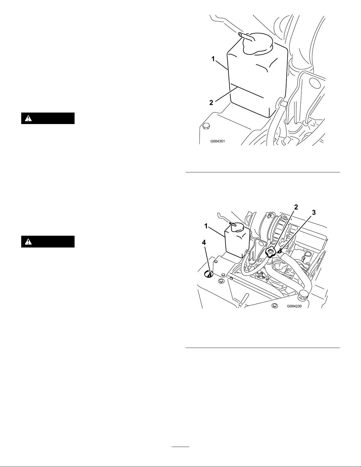
1.Checkthelevelofcoolantintheexpansiontank
(Figure20).
Thecoolantlevelshouldbeatorabovethemarkon
thesideofthetank.
Figure20
1.Expansiontank2.Fullmark
2.Ifthecoolantlevelislow ,completethefollowing
procedure:
A.Removethecoolant-llcap(Figure21).
Figure21
1.Expansiontank3.Topcoolant-bleedvalve
2.Coolant-llcapandller
neck
B.Openthefrontandtopcoolant-bleedvalves
(Figure21).
C.Pourcoolantintothecoolantllerneckuntil
thecoolantbeginstocomeoutofthefront
coolant-bleedvalve(Figure21).
D.Closethefrontcoolant-bleedvalve(Figure21).
E.Pourcoolantintothecoolantllerneckuntil
thecoolantbeginstocomeoutofthetop
coolant-bleedvalve(Figure21).
F.Closethetopcoolant-bleedvalve(Figure21).
4.Frontcoolant-bleedvalve
20
Page 21
G.Pourcoolantintothecoolantllerneckuntilthe
coolantlevelcomesintothellerneck(Figure21).
H.Installthecoolant-llcap(Figure21).
I.Addcoolantintotheexpansiontankuntilit
reachestheFulllineonthesideofthetank
(Figure21).
3.Installtheexpansiontankcap.
BleedingtheFuelSystem
Youmustbleedthefuelsystembeforestartingtheengineif
anyofthefollowingsituationshaveoccurred:
•Initialstartupofanewmachine.
•Enginehasceasedrunningduetolackoffuel.
•Maintenancehasbeenperformeduponfuelsystem
components(e.g.,lterreplaced).
DANGER
Undercertainconditions,dieselfuelandfuel
vaporsarehighlyammableandexplosive.Are
orexplosionfromfuelcanburnyouandothersand
cancausepropertydamage.
•Useafunnelandllthefueltankoutdoors,in
anopenarea,whentheengineisoffandiscold.
Wipeupanyfuelthatspills.
•Donotllthefueltankcompletelyfull.Add
fueltothefueltankuntilthelevelis1/4to1/2
in.(6to13mm)belowthebottomoftheller
neck.Thisemptyspaceinthetankallowsthe
fueltoexpand.
•Neversmokewhenhandlingfuel,andstayaway
fromanopenameorwherefuelfumesmaybe
ignitedbyaspark.
•Storefuelinaclean,safety-approvedcontainer
andkeepthecapinplace.
1.Ensurethatthefueltankisatleasthalffull.
2.Openthehood.
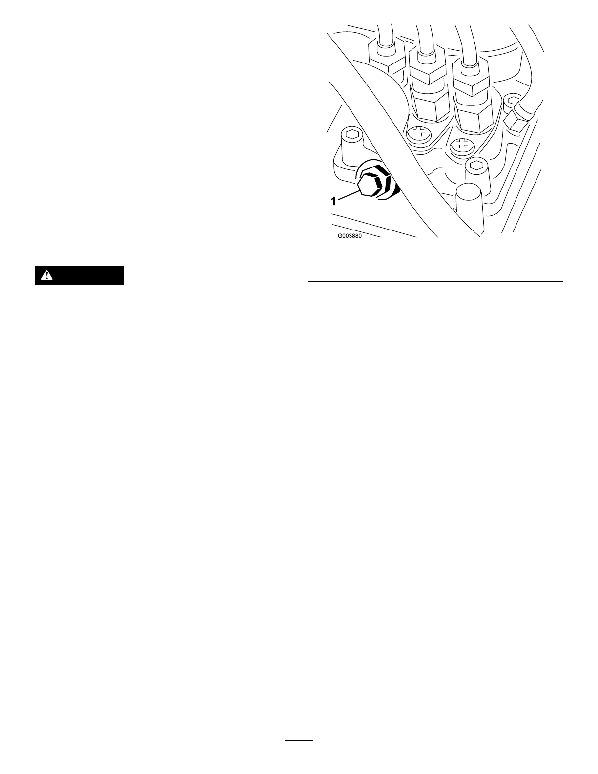
3.Opentheairbleedscrewonthefuel-injectionpump
(Figure22).
Figure22
1.Fuel-injectionpumpbleedscrew
4.TurnthekeyintheignitionswitchtotheONposition.
Theelectricfuelpumpwillbeginoperation,thereby
forcingairoutaroundtheairbleedscrew .Leavethe
keyintheONpositionuntilasolidstreamoffuelows
outaroundthescrew .
5.TightenthescrewandturnthekeytotheOFFposition.
Note:Normally,theengineshouldstartaftertheabove
bleedingproceduresarefollowed.However,ifenginedoes
notstart,airmaybetrappedbetweeninjectionpumpand
injectors;contactyourAuthorizedServiceDealer.
StartingandShuttingOffthe Engine
StartingtheEngine
1.Ensurethattheauxiliary-hydraulicsleverisinneutral.
2.MovethethrottlelevermidwaybetweenSLOW(turtle)
andFAST(rabbit)positions.
3.TurntheignitionkeytotheRUNposition.
4.Presstheglowplugswitchandholditfor10seconds.
5.TurntheignitionkeytotheSTARTposition.Whenthe
enginesstarts,releasethekey.
Important:Donotengagethestarterformore
than10secondsatatime.Iftheenginefailsto
start,allowa30secondcool-downperiodbetween
attempts.Failuretofollowtheseinstructionscan
burnoutthestartermotor.
6.Movethethrottlelevertodesiredsetting.
Important:Iftheengineisrunathighspeeds
whenthehydraulicsystemiscold(i.e.,whenthe
ambientairtemperatureisnearfreezingorlower),
21
Page 22
hydraulicsystemdamagecouldoccur.When
startingtheengineincoldconditions,allowthe
enginetoruninthemiddlethrottlepositionfor
2to5minutesbeforemovingthethrottletofast
(rabbit).
Note:Ifoutdoortemperatureisbelowfreezing,store
thetractionunitinagaragetokeepitwarmerandaid
instarting.
ShuttingOfftheEngine
1.MovethethrottlelevertotheSLOW(turtle)position.
2.Lowertheloaderarmstotheground.
3.Turntheignitionkeyoff.
Note:Iftheenginehasbeenworkinghardorishot,
letitidleforaminutebeforeturningtheignitionkey
off.Thishelpscooltheenginebeforeitisstopped.In
anemergency,youcanshutofftheengineimmediately.
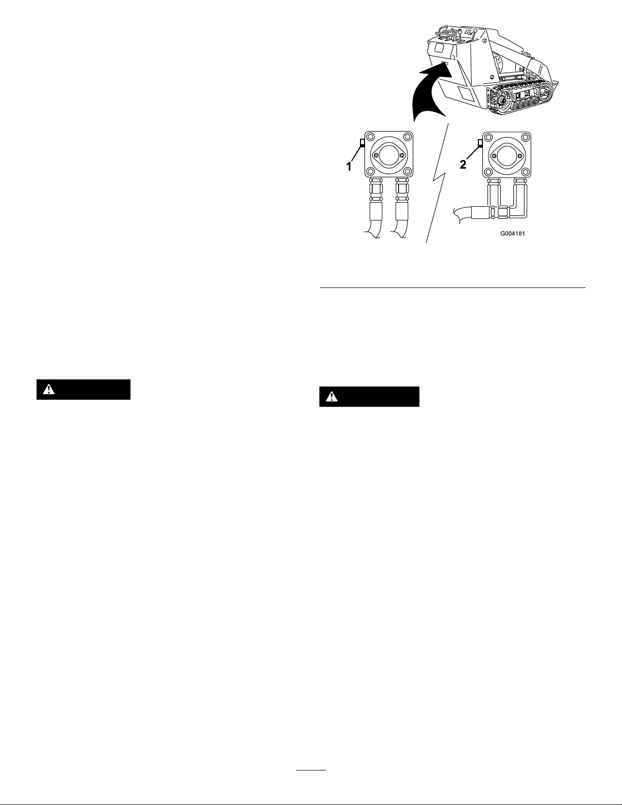
Figure23
1.Lefttowvalve(righttrack)2.Righttowvalve(lefttrack)
StoppingtheTractionUnit
Tostopthetractionunit,releasethetractioncontrol,move
thethrottlelevertoslow(turtle),lowerloaderarmstothe
ground,andshutofftheengine.Settheparkingbrakeand
removethekey .
CAUTION
Achildoruntrainedbystandercouldattemptto
operatethetractionunitandbeinjured.
Removethekeyfromtheswitchwhenleavingthe
tractionunit,evenifjustforafewseconds.
MovingaNon-Functioning TractionUnit
Important:Donottoworpullthetractionunitwithout
rstopeningthetowvalves,orthehydraulicsystemwill
bedamaged.
1.Shutofftheengine.
2.Opentherearaccesscover.
4.Towthetractionunitasrequired.
5.Whenthetractionunithasbeenrepaired,closethetow
valvesbeforeoperatingit.
UsingtheCylinderLock
WARNING
Theloaderarmsmaylowerwhenintheraised
positioncrushinganyoneunderthem.
Installthecylinderlockbeforeperforming
maintenancethatrequiresraisedloaderarms.
InstallingtheCylinderLock
1.Removetheattachment.
2.Raisetheloaderarmstothefullyraisedposition.
3.Shutofftheengine.
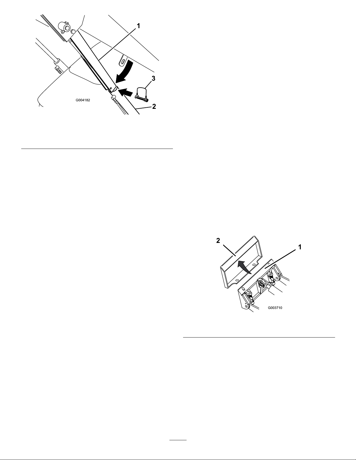
4.Removethelynchpinsecuringthecylinderlocktothe
loaderarm(Figure24).
3.Usingawrench,turnthetowvalvesonthehydraulic
pumpstwicecounter-clockwise(Figure23).
22
Page 23
G004182
3
2
1
Figure24
1.Cylinderlock
2.Liftcylinder
5.Lowerthecylinderlockoverthecylinderrodand
secureitwiththelynchpin(Figure24).
6.Slowlylowertheloaderarmsuntilcylinderlock
contactsthecylinderbodyandrodend.
3.Lynchpin
UsingAttachments
Important:Ifyouareusinganattachmentwitha
serialnumberof200999999orearlier,themanualfor
theattachmentmaycontaininformationspecictothe
useoftheattachmentwithothertractionunits,suchas
settingsfortheowdividercontrolandspeedselector
leverandtheuseofacounterweightonthetractionunit.
ThesesystemsarebuiltintotheTX,andyoushould
ignoreanyreferencestothem.
InstallinganAttachment
Important:UseonlyToro-approvedattachments.
Attachmentscanchangethestabilityandtheoperating
characteristicsofthetractionunit.Thewarrantyofthe
tractionunitmaybevoidedifusedwithunapproved
attachments.
Important:Beforeinstallingtheattachment,ensure
thatthemountplatesarefreeofanydirtordebrisand
thatthepinsrotatefreely.Ifthepinsdonotrotatefreely,
greasethem.
1.Positiontheattachmentonalevelsurfacewithenough
spacebehindittoaccommodatethetractionunit.
Removing/StoringtheCylinderLock
Important:Ensurethatthecylinderlockisremoved
fromtherodandfullysecuredinthestorageposition
beforeoperatingthetractionunit.
1.Starttheengine.
2.Raisetheloaderarmstothefullyraisedposition.
3.Shutofftheengine.
4.Removethelynchpinsecuringthecylinderlock.
5.Rotatethecylinderlockuptotheloaderarmand
secureitwiththelynchpin.
6.Lowertheloaderarms.
2.Starttheengine.
3.Tilttheattachmentmountplateforward.
4.Positionmountplateintotheupperlipofthe
attachmentreceiverplate(Figure25).
Figure25
1.Mountplate2.Receiverplate
5.Raisetheloaderarmswhiletiltingbackthemountplate
atthesametime.
Important:Theattachmentshouldberaised
enoughtocleartheground,andthemountplate
shouldbetiltedallthewayback.
6.Shutofftheengine.
23
Page 24
7.Engagethequick-attachpins,ensuringthattheyare
fullyseatedinthemountplate(Figure26).
ConnectingtheHydraulicHoses
Important:Ifthepinsdonotrotatetothe
engagedposition,themountplateisnotfully
alignedwiththeholesintheattachmentreceiver
plate.Checkthereceiverplateandcleanitif
necessary.
WARNING
Hydraulicuidescapingunderpressurecan
penetrateskinandcauseinjury.Fluidinjectedinto
theskinmustbesurgicallyremovedwithinafew
hoursbyadoctorfamiliarwiththisformofinjury
otherwisegangrenemayresult.
•Keepyourbodyandhandsawayfrompinhole
leaksornozzlesthatejecthigh-pressure
hydraulicuid.
•Usecardboardorpapertondhydraulicleaks;
neveruseyourhands.
CAUTION
Hydrauliccouplers,hydrauliclines/valves,and
hydraulicuidmaybehot.Ifyoucontacthot
components,youmaybeburned.
•Weargloveswhenoperatingthehydraulic
couplers.
•Allowthetractionunittocoolbeforetouching
hydrauliccomponents.
Figure26
1.Quick-attachpins(shown
inengagedposition)
2.Disengagedposition
3.Engagedposition
WARNING
Ifyoudonotfullyseatthequick-attachpins
throughtheattachmentmountplate,the
attachmentcouldfalloffthetractionunit,
crushingyouorbystanders.
Ensurethatyourquick-attachpinsarefully
seatedintheattachmentmountplate.
•Donottouchhydraulic-uidspills.
Iftheattachmentrequireshydraulicsforoperation,connect
thehydraulichosesasfollows:
1.Shutofftheengine.
2.Movetheauxiliary-hydraulicsleverforward,backward,
andbacktotheNEUTRALpositiontorelievepressure
atthehydrauliccouplers.
3.Movetheauxiliary-hydraulicsleverforwardintothe
DETENTposition.
4.Removetheprotectivecoversfromthehydraulic
couplersonthetractionunit.
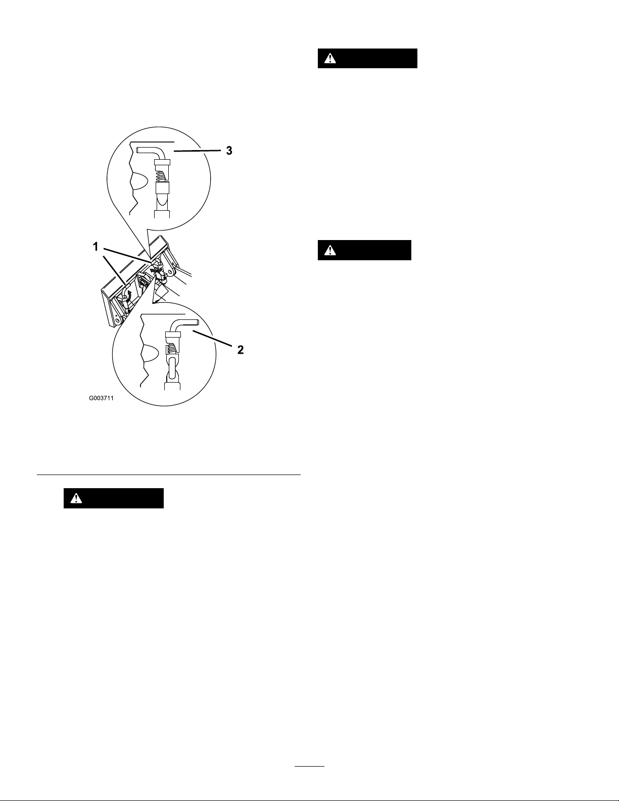
5.Ensurethatallforeignmatteriscleanedfromthe
hydraulicconnectors.
6.Pushtheattachmentmaleconnectorintothefemale
connectoronthetractionunit.
Note:Whenyouconnecttheattachmentmale
connectorrst,youwillrelieveanypressurebuildupin
theattachment.
7.Pushtheattachmentfemaleconnectorintothemale
connectoronthetractionunit.
8.Conrmthattheconnectionissecurebypullingon
thehoses.
9.Movetheauxiliary-hydraulicslevertotheNEUTRAL
position.
24
Page 25
RemovinganAttachment
1.Lowertheattachmenttotheground.
2.Shutofftheengine.
3.Disengagethequick-attachpinsbyturningthemto
theoutside.
4.Iftheattachmentuseshydraulics,movethe
auxiliary-hydraulicsleverforward,backward,andback
totheNEUTRALpositiontorelievepressureatthe
hydrauliccouplers.
5.Iftheattachmentuseshydraulics,slidethecollarback
onthehydrauliccouplersanddisconnectthem.
Important:Connecttheattachmenthoses
togethertopreventhydraulicsystemcontamination
duringstorage.
6.Installtheprotectivecoversontothehydrauliccouplers
onthetractionunit.
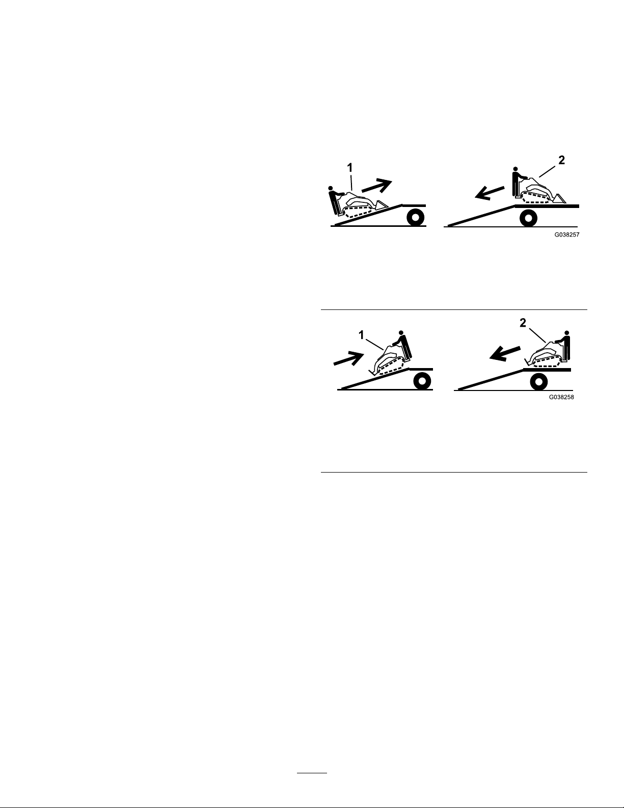
LoadingtheMachine
Useextremecautionwhenloadingortheunloadingmachine
ontoatraileroratruck.Useafull-widthrampthatiswider
thanthemachineforthisprocedure.Loadandunloadthe
machinewiththeheavyenduptheramp.Ifthemachinehas
anattachment,drivethemachineforwarduptherampand
backitdowntheramp(Figure27);ifthemachinedoesnot
haveanattachment,backthemachineuptherampanddrive
itforwarddowntheramp(Figure28).
Figure27
Machineswithanattachment
7.Starttheengine,tiltthemountplateforward,andback
thetractionunitawayfromtheattachment.
SecuringtheTractionUnitfor Transport
Whentransportingthetractionunitonatrailer,alwaysuse
thefollowingprocedure:
Important:Donotoperateordrivethetractionunit
onroadways.
1.Lowertheloaderarms,settheparkingbrake,andshut
offtheengine.
2.Securethetractionunittothetrailerwithchainsor
strapsusingthetie-down/liftloops(Figure4)tosecure
therearofthetractionunitandtheloaderarms/mount
platetosecurethefrontofthetractionunit.
LiftingtheTractionUnit
Youcanliftthetractionunitusingthetie-down/liftloopsas
liftpointsindicatedintheProductOverview(page13).
1.Drivethemachineforward
uptheramp.
Machineswithoutanattachment
1.Backthemachineupthe
ramp.
Important:Donotusenarrowindividualrampsfor
eachsideofthemachine.
Ensurethattherampislongenoughsothattheanglewith
thegrounddoesnotexceed17degrees(Figure29).Onat
ground,thisrequiresaramptobeatleast4timesaslongas
theheightofthetrailerortruckbedtotheground.Asteeper
anglemaycausemowercomponentstogetcaughtasthe
machinemovesfromtheramptothetrailerortruck.Steeper
anglesmayalsocausethemachinetotiporlosecontrol.If
youareloadingthemachineonornearaslope,positionthe
trailerortrucksothatitisonthedownsideoftheslopeand
therampextendsuptheslope.Thisminimizestheramp
angle.
2.Backthemachinedown
theramp.
Figure28
2.Drivethemachineforward
downtheramp.
25
Page 26

WARNING
g027996
5
1
2
6
Loadingamachineontoatrailerortruckincreases
thepossibilityoftip-overandcouldcauseserious
injuryordeath.
•Useextremecautionwhenoperatingamachine
onaramp.
•Useonlyafull-widthramp;donotuseindividual
rampsforeachsideofthemachine.
•Donotexceeda17-degreeanglebetweenthe
rampandthegroundorbetweentherampand
thetrailerortruck.
•Ensurethatthelengthoframpisatleast4times
aslongastheheightofthetrailerortruckbedto
theground.Thisensuresthatrampangledoes
notexceed17degreesonatground.
•Loadandunloadthemachinewiththeheavy
enduptheramp.
•Avoidsuddenaccelerationordecelerationwhile
drivingthemachineonarampasthiscould
causealossofcontroloratip-oversituation.
Figure29
1.Full-widthrampinstowed
position
2.Sideviewoffull-width
rampinloadingposition
3.Notgreaterthan
17degrees
4.Rampisatleast4times
aslongastheheightof
thetrailerortruckbedto
theground
5.H=heightofthetraileror
truckbedtotheground
6.Trailer
26
Page 27

Maintenance
Note:Determinetheleftandrightsidesofthemachinefromthenormaloperatingposition.
RecommendedMaintenanceSchedule(s)
MaintenanceService
Interval
Aftertherst8hours
Aftertherst50hours
Beforeeachuseordaily
Every25hours
Every100hours
MaintenanceProcedure
•Replacethehydrauliclter.
•Changetheengineoilandlter.
•Checkandadjustthetracktension.
•Checktheengine-oillevel.
•Checkthecoolingsystem.
•Greasethetractionunit.(Greaseimmediatelyaftereverywashing.)
•Checktheair-lterserviceindicator.
•Drainwaterandothercontaminantsfromthefuellter/waterseparator.
•Cleanthetracks.
•Checkthetracksforexcessivewear(Ifthetracksareworn,replacethem.)
•Cleantheradiator.
•Removedebrisfromthetractionunitandsidescreens.
•Checkforloosefasteners.
•Checkthehydraulicuidlevel.
•Removeair-cleanercover,cleanoutdebris,andchecktheair-lterserviceindicator.
•Changetheengineoil.
•Checkthebattery-electrolytelevel(replacementbatteryonly).
•Checkthebatterycableconnections.
•Checkandadjustthetracktension.
•Checkthecoolingsystemhoses.
•Checkthealternator/fanbelttension(refertotheengineowner’smanualfor
instructions).
•Checkthehydrauliclinesforleaks,loosettings,kinkedlines,loosemounting
supports,wear,weather,andchemicaldeterioration.
•Checkfordirtbuild-upinthechassis.
Every200hours
Every250hours
Every400hours
Every500hours
Every600hours
Every1,500hours
Yearly
Yearlyorbeforestorage
Every2years
•Changetheoillter.
•Replacethehydrauliclter.
•Checkandgreasetheroadwheels.
•Checkthefuellinesandconnectionsfordeterioration,damage,orlooseconnections.
•Replacethefuelltercanisterandin-linelter.
•Changethehydraulicuid.
•Replacethealternator/fanbelt(refertotheengineowner’smanualforinstructions).
•Replacethesafetyairlter.
•Replaceallmovinghydraulichoses.
•Changetheenginecoolant(AuthorizedServiceDealeronly).
•Checktheconditionofthehydraulicpumpbelt.
•Checkandadjustthetracktension.
•T ouchupchippedpaint.
•Drainandcleanthefueltank(AuthorizedServiceDealeronly).
Important:Refertoyourengineowner’smanualforadditionalmaintenanceprocedures.
27
Page 28

CAUTION
3
G009691
Ifyouleavethekeyintheignitionswitch,someonecouldaccidentlystarttheengineandseriouslyinjure
youorotherbystanders.
Removethekeyfromtheignitionbeforeyoudoanymaintenance.
Premaintenance
Procedures
Beforeopeninganyofthecovers,shutofftheengineand
removethekey.Allowtheenginetocoolbeforeopening
anycovers
OpeningtheHood
1.Loosenthehood-lockingscrew(Figure30)
ClosingtheHood
1.Liftuponthetabsecuringtheprop-rod(Figure31)
Figure31
1.Prop-rodtab
2.Lowerthehoodandsecureitbypushingdownonthe
frontofthehooduntilitlocksinplace.
Figure30
1.Hood3.Hood-lockingscrew
2.Hood-latchlever
2.Turnthehoodlatchclockwise(Figure30).
3.Swingthehoodup(Figure30).
3.Tightenthehood-lockingscrewtosecurethelatch
(Figure30).
28
Page 29

OpeningtheRearAccess
RemovingtheSideScreens
Cover
1.Unscrewthe2handknobssecuringtherearaccess
covertothemachine(Figure32).
Figure32
1.Handknobs
2.Tilttherearaccesscoverdownandremovetoaccess
theinternalcomponents(Figure32).
ClosingtheRearAccessCover
1.Openthehood.
2.Slidethesidescreens(Figure33)upandoutofthe
slotsinthefrontscreenandframe.
Figure33
1.Sidescreen
1.Movetherearaccesscoverinplaceoverthebackof
thetractionunitmakingsurethatthetabslineupin
theslots.
2.Pushtheaccesscoverforward,liningupthehand-knob
screwswiththethreadedholesinthemachine.
3.Screwthehandknobstighttosecuretherearaccess
coverinplace.
InstallingtheSideScreens
Slidethesidescreensintoplaceintheslotsinthefrontscreen
andframe.
29
Page 30

Lubrication
g034220
EngineMaintenance
GreasingtheTractionUnit
ServiceInterval:Beforeeachuseordaily(Grease
immediatelyaftereverywashing.)
GreaseType:General-purposegrease.
1.Lowertheloaderarmsandshutofftheengine.
Removethekey.
2.Cleanthegreasettingswitharag.
3.Connectagreaseguntoeachtting(Figure34and
Figure35).
ServicingtheAirCleaner
ServiceInterval:Beforeeachuseordaily—Checkthe
air-lterserviceindicator.
Every25hours—Removeair-cleanercover,cleanout
debris,andchecktheair-lterserviceindicator.
Every600hours—Replacethesafetyairlter.
ServicingtheAir-CleanerCoverand
Body
Important:Servicetheaircleanerlteronlywhenthe
serviceindicatorshowsred(Figure36).Changingthe
airlterbeforeitisnecessaryonlyincreasesthechance
ofdirtenteringtheenginewhenthelterisremoved.
1.Lowertheloaderarms,shutofftheengine,andremove
thekey.
2.Openthehood.
3.Checktheair-cleanerbodyfordamage,whichcould
causeanairleak..Checkthewholeintakesystemfor
leaks,damage,orloosehoseclamps.Replaceofrepair
anddamagedcomponents.
Figure34
Figure35
4.Pumpgreaseintothettingsuntilgreasebeginsto
oozeoutofthebearings(approximately3pumps).
5.Wipeupanyexcessgrease.
4.Releasethelatchesontheaircleanerandpullthe
air-cleanercoverofftheair-cleanerbody(Figure36).
Important:Donotremovetheairlters.
Figure36
1.Air-lterserviceindicator
2.Airlterbody
3.Primarylter
5.Squeezethedustcapsidestoopenitandknockthe
dustout.
6.Cleantheinsideoftheair-cleanercoverwith
compressedair.
7.Checktheair-lterserviceindicator.
4.Air-cleanercover
5.Latches
6.Dustcap
•Iftheserviceindicatorisclear,cleananydebris
fromcoverandinstallcover.
30
Page 31

Ensurethatthecoverisseatedcorrectlyandseals
withtheair-cleanerbody.
•Iftheserviceindicatorisred,replacetheairlter
asdescribedinReplacingtheFilters(page31).
ServicingtheEngineOil
ServiceInterval:Aftertherst50hours—Changethe
engineoilandlter.
Every100hours—Changetheengineoil.
ReplacingtheFilters
1.Gentlyslidetheprimarylteroutoftheair-cleaner
body(Figure36).Avoidknockingthelterintothe
sideofthebody .
Important:Donotattempttocleantheprimary
lter.
2.Inspectthenewlter(s)fordamagebylookingintothe
lterwhileshiningabrightlightontheoutsideofthe
lter.Holesinthelterappearasbrightspots.Inspect
theelementfortears,anoilylm,ordamagetothe
rubberseal.Ifthelterisdamageddonotuseit.
3.Carefullyslidetheprimarylterintothelterbody
(Figure36).Ensurethatitisfullyseatedbypushingon
theouterrimofthelterwhileinstallingit.
Important:Donotpressonthesoftinsidearea
ofthelter.
4.Installtheair-cleanercoverwiththesideindicatedas
UPfacingupandsecurethelatches(Figure36).
5.Closethehood.
Every200hours—Changetheoillter.
OilT ype:Detergentdieselengineoil(APIserviceCH-4or
higher)
CrankcaseCapacity:withlter,3.7L(0.98USgallons)
Viscosity:Seetablebelow
Figure37
ChangingtheOil
1.Starttheengineandletitrunfor5minutes.This
warmstheoilsothatitdrainsbetter.
2.Parkthetractionunitsothatthedrainsideisslightly
lowerthantheoppositesidetoensurethattheoil
drainscompletely.
3.Lowertheloaderarms,settheparkingbrake,shutoff
theengine,andremovethekey .
CAUTION
Componentswillbehotifthetractionunithas
beenrunning.Ifyoutouchhotcomponents,
youmaybeburned.
Allowthetractionunittocoolbefore
performingmaintenanceortouching
componentsunderthehood.
4.Removethedrainplug(Figure38).
31
Page 32
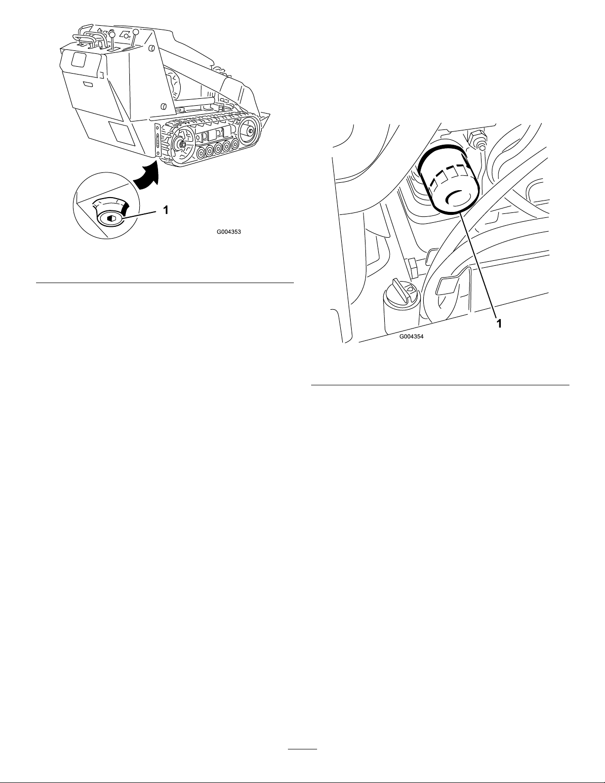
Figure38
1.Oildrainplug
5.Whentheoilhasdrainedcompletely ,replacetheplug.
Note:Disposeoftheusedoilatacertiedrecycling
center.
ChangingtheOilFilter
1.Draintheoilfromtheengine;refertoChangingthe
Oil(page31).
2.Placeashallowpanorragundertheltertocatchoil.
3.Removetheoldlter(Figure39)andwipethesurface
ofthelteradaptergasket.
6.Removetheoilllcapandslowlypourapproximately
80%ofthespeciedamountofoilinthroughthe
valvecover.
7.Checktheoillevel;refertoCheckingtheEngine-Oil
Level(page18).
8.Slowlyaddadditionaloiltobringtheleveltotheupper
holeonthedipstick.
9.Replacethellcap.
Figure39
1.Oillter
4.Pournewoilofthepropertypethroughthecenter
holeofthelter.Stoppouringwhentheoilreaches
thebottomofthethreads.
5.Allowaminuteortwofortheoiltobeabsorbedby
ltermaterial,thenpourofftheexcessoil.
6.Applyathincoatofnewoiltotherubbergasketon
thereplacementlter.
7.Installthereplacementoilltertothelteradapter.
Turntheoillterclockwiseuntiltherubbergasket
contactsthelteradapter,thentightenthelteran
additional1/2turn.
8.Fillthecrankcasewiththepropertypeofnewoil;refer
toChangingtheOil(page31).
32
Page 33

FuelSystem
Maintenance
DANGER
Undercertainconditions,dieselfuelandfuel
vaporsarehighlyammableandexplosive.Are
orexplosionfromfuelcanburnyouandothersand
cancausepropertydamage.
•Useafunnelandllthefueltankoutdoors,in
anopenarea,whentheengineisoffandiscold.
Wipeupanyfuelthatspills.
•Donotllthefueltankcompletelyfull.Add
fueltothefueltankuntilthelevelis1/4to1/2
in.(6to13mm)belowthebottomoftheller
neck.Thisemptyspaceinthetankallowsthe
fueltoexpand.
•Neversmokewhenhandlingfuel,andstayaway
fromanopenameorwherefuelfumesmaybe
ignitedbyaspark.
DrainingtheFuelFilter/Water Separator
ServiceInterval:Beforeeachuseordaily
1.Locatethefuellterontherightsideoftheengine
(Figure40)andplaceacleancontainerunderit.
•Storefuelinaclean,approvedcontainerand
keepthecapinplace.
CheckingtheFuelLinesand Connections
ServiceInterval:Every400hours/Y early(whichevercomes
rst)
Inspectthefuellinesandconnectionsfordeterioration,
damage,orlooseconnections.Tightenanylooseconnections
andcontactyourAuthorizedServiceDealerforassistance
inxingdamagedfuellines.
Figure40
1.Fuelltercanister/water
separator
2.Drainvalve
2.Loosenthedrainvalveonthebottomofthelter
canisterandallowthewatertodrain.
3.Whennished,tightenthedrainvalve.
3.Hoseclamps
4.In-linelter
33
Page 34

ReplacingtheFuelFilter CanisterandIn-lineFilter
ServiceInterval:Every400hours
ElectricalSystem
Maintenance
1.Locatethefuelltersontherightsideoftheengine
(Figure40)andplaceacleancontainerunderit.
2.Cleantheareawheretheltercanistermounts(Figure
40).
3.Removetheltercanisterandcleanthemounting
surface(Figure40).
4.Lubricatethegasketonthenewltercanisterwith
cleanoil.
5.Installtheltercanisterbyhanduntilthegasket
contactsthemountingsurface,thenrotateitan
additional1/2turn(Figure40).
6.Locatethein-linelterbehindthefuelltercanister
(Figure40)andnotethedirectionofowarrowon
thesideofthein-linelter.
7.Opentheclampsoneachendofthein-linelterand
slidethehosesoffit(Figure40).Discardthelter.
8.Slidethehosesovertheendofanewlter(Figure40),
ensuringthatthearrowonthelterispointinginthe
samedirectionasthearrowontheoldlter.
9.Securethehoseswiththehoseclamps.
ServicingtheBattery
ServiceInterval:Every100hours—Checkthe
battery-electrolytelevel(replacement
batteryonly).
Every100hours—Checkthebatterycable
connections.
WARNING
CALIFORNIA
Proposition65Warning
Batteryposts,terminals,andrelated
accessoriescontainleadandleadcompounds,
chemicalsknowntotheStateofCalifornia
tocausecancerandreproductiveharm.
Washhandsafterhandling.
Important:Thefollowingproceduresapplywhen
servicinga(dry)batterythathasreplacedtheoriginal
battery.Theoriginal(wet)batterydoesnotrequire
service.
DrainingtheFuelTank
ServiceInterval:Every2years
HaveanAuthorizedServiceDealerdrainandcleanthefuel
tank.
Alwayskeepthebatterycleanandfullycharged.Useapaper
toweltocleanthebatterycase.Ifthebatteryterminalsare
corroded,cleanthemwithasolutionof4partswaterand
1partbakingsoda.Applyalightcoatingofgreasetothe
batteryterminalstoreducecorrosion.
Voltage:12V ,585A(coldcranking)
CheckingtheElectrolyteLevel
1.Shutofftheengineandremovethekey.
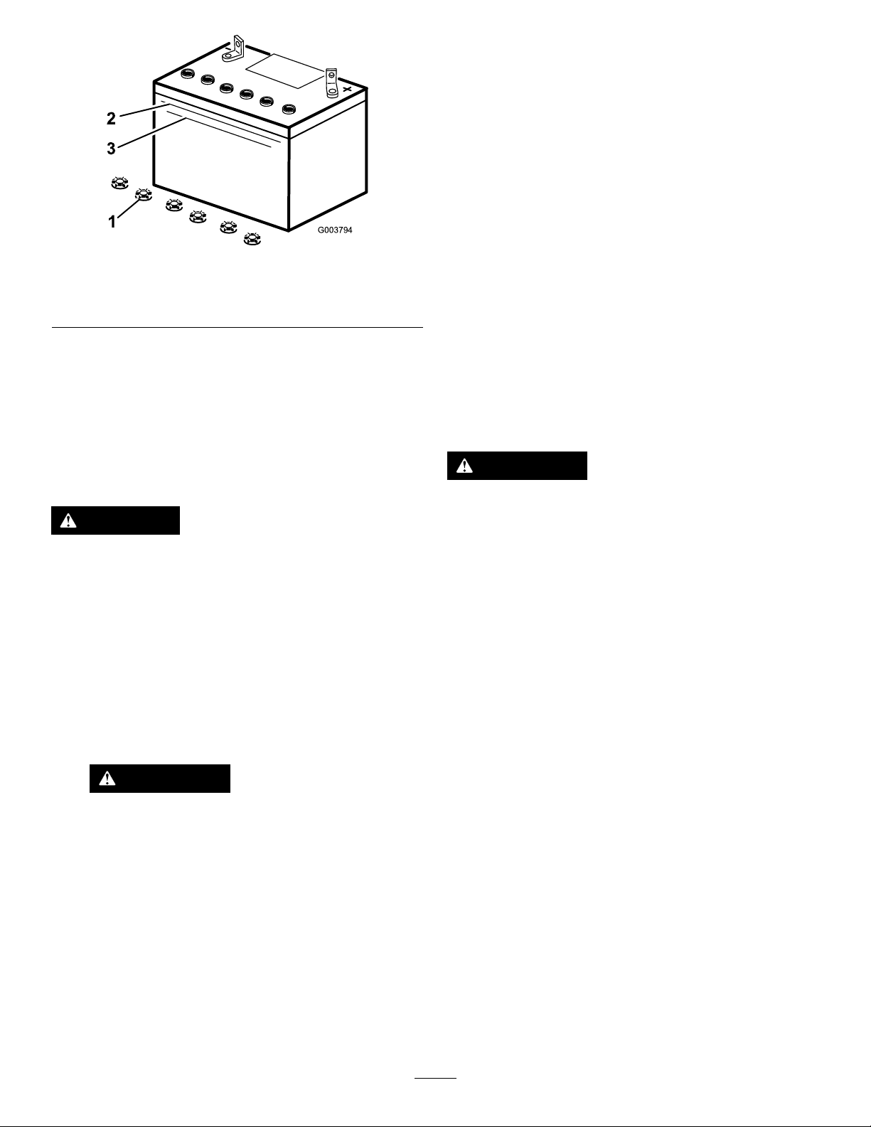
2.Lookatthesideofthebattery.Theelectrolytemust
beuptotheUpperline(Figure41).Donotallowthe
electrolytetofallbelowtheLowerline(Figure41).
34
Page 35
2
3
1
G003794
Figure41
1.Fillercaps3.Lowerline
2.Upperline
3.Iftheelectrolyteislow ,addtherequiredamountof
distilledwater;refertoAddingWatertotheBattery
(page35).
3.Removethebatteryfromthetractionunit.
Important:Neverllthebatterywithdistilled
waterwhilethebatteryisinstalledinthetraction
unit.Electrolytecouldbespilledonotherparts
andcausecorrosion.
4.Cleanthetopofthebatterywithapapertowel.
5.Removethellercapsfromthebattery(Figure41).
6.Slowlypourdistilledwaterintoeachbatterycelluntil
theelectrolytelevelisuptotheUpperline(Figure41)
onthebatterycase.
Important:Donotoverllthebatterybecause
electrolyte(sulfuricacid)cancausesevere
corrosionanddamagetothechassis.
7.Wait5to10minutesafterllingthebatterycells.Add
distilledwater,ifnecessary,untiltheelectrolytelevelis
uptotheUpperline(Figure41)onthebatterycase.
8.Installthebatteryllercaps.
AddingWatertotheBattery
Thebesttimetoadddistilledwatertothebatteryisjust
beforeyouoperatethetractionunit.Thisletsthewatermix
thoroughlywiththeelectrolytesolution.
DANGER
Batteryelectrolytecontainssulfuricacidwhichisa
deadlypoisonandcausessevereburns.
•Donotdrinkelectrolyteandavoidcontactwith
skin,eyesorclothing.Wearsafetyglassesto
shieldyoureyesandrubberglovestoprotect
yourhands.
•Fillthebatterywherecleanwaterisalways
availableforushingtheskin.
1.Disconnectthenegative(black)cablefromthenegative
(-)batterypost.
WARNING
Incorrectbatterycableroutingcoulddamage
thetractorandcables,causingsparks.Sparks
cancausethebatterygassestoexplode,
resultinginpersonalinjury.
ChargingtheBattery
WARNING
Chargingthebatteryproducesgassesthatcan
explode.
Neversmokenearthebatteryandkeepsparksand
amesawayfrombattery.
Important:Alwayskeepthebatteryfullycharged(1.265
specicgravity).Thisisespeciallyimportanttoprevent
batterydamagewhenthetemperatureisbelow0°C
(32°F).
1.Checktheelectrolytelevel;refertoCheckingthe
ElectrolyteLevel(page34).
2.Makesurethatthellercapsareinstalledinthebattery.
3.Chargethebatteryfor10to15minutesat25to30Aor
30minutesat4to6A(Figure42).Donotovercharge
thebattery.
•Alwaysdisconnectthenegative(black)
batterycablebeforedisconnectingthe
positive(red)cable.
•Alwaysconnectthepositive(red)battery
cablebeforeconnectingthenegative
(black)cable.
2.Disconnectthepositive(red)cablefromthepositive
(+)batterypost.
35
Page 36
1
2
3
4
G003792
Figure42
1.Shutofftheengineandremovethekey.
2.Raisethehood.
3.Pullthehairpincotterfromthebottomendofthe
hoodprop-rodandslidetheproprodoutofthe
retainingbracketsandtheprop-rodtab(Figure44).
1.Positivebatterypost
2.Negativebatterypost
3.Red(+)chargerlead
4.Black(-)chargerlead
4.Whenthebatteryisfullycharged,unplugthecharger
fromtheelectricaloutlet,thendisconnectthecharger
leadsfromthebatteryposts(Figure42).
ServicingtheFuses
Theelectricalsystemisprotectedbyfuses.Itrequires
nomaintenance;however,ifafuseblows,checkthe
component/circuitforamalfunctionorashort.Figure43
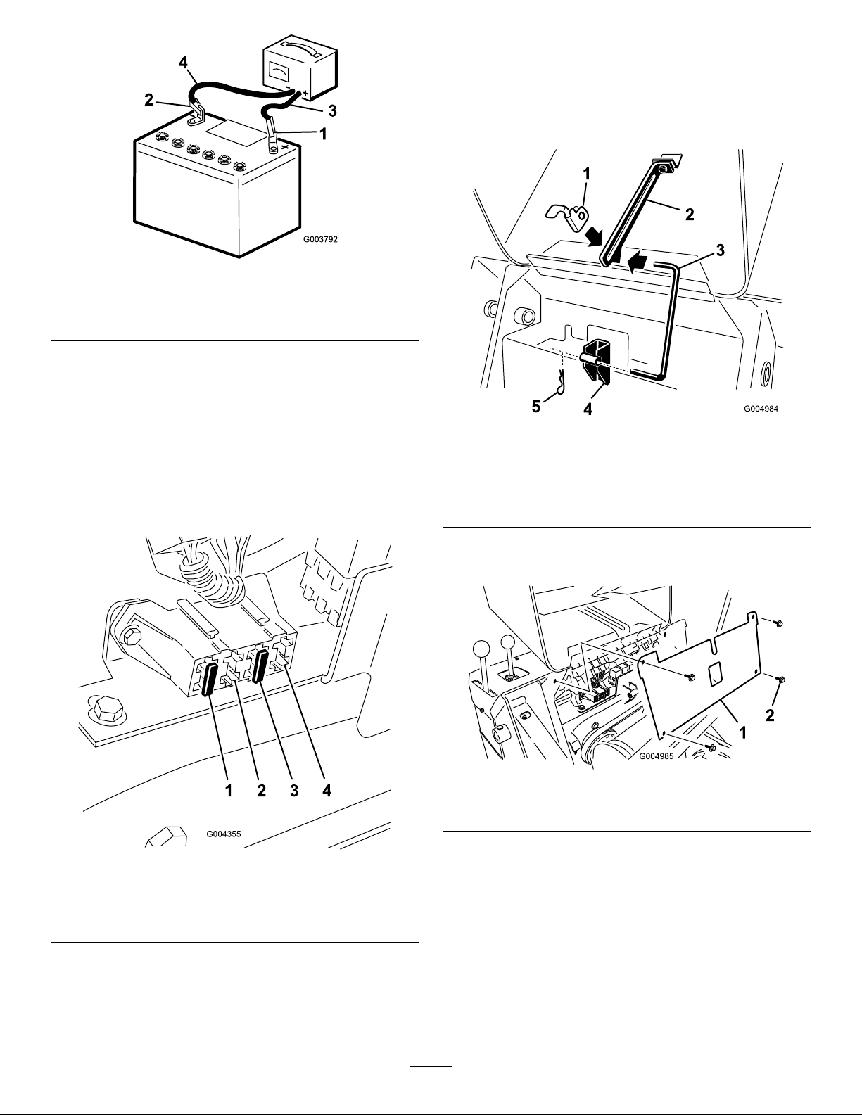
illustratesthefuseblockandidentiesthefusepositions.
Figure44
1.Prop-rodtab4.Retaining
bracket—bottom
2.Retainingbracket—top5.Hairpincotter
3.Prop-rod
4.Removethe4screwssecuringthefusepanelandthen
pullthepaneloutanduptoremoveit(Figure45).
Figure43
1.Fuse(30A)3.Fuse(10A)
2.Empty
Note:Ifthetractionunitdoesnotstart,eitherthemain
circuitorcontrolpanel/relayfusecouldbeblown.
4.Openpositionforoptional
accessories
Toaccessthefuses,youmustremovethefusepanel,as
follows:
Figure45
1.Fusepanel
2.Screw
5.Checkthefuses.
6.Installthefusepanelusingthe4screwsremoved
previously.
7.Installtheprop-rodintotheretainingbracketsand
prop-rodtabandsecureitwiththehairpincotter
(Figure44).
8.Closethehood.
36
Page 37
DriveSystem
Maintenance
ServicingtheTracks
ServiceInterval:Aftertherst50hours—Checkandadjust
thetracktension.
Beforeeachuseordaily—Cleanthetracks.
Beforeeachuseordaily—Checkthetracksfor
excessivewear(Ifthetracksareworn,replacethem.)
Every100hours—Checkandadjustthetracktension.
Every250hours/Yearly(whichevercomes
rst)—Checkandgreasetheroadwheels.
CleaningtheTracks
1.Withabucketontheloaderarms,lowerthebucketto
thegroundsothatthefrontofthetractionunitliftsoff
thegroundafewinches.
2.Shutofftheengine,andremovethekey .
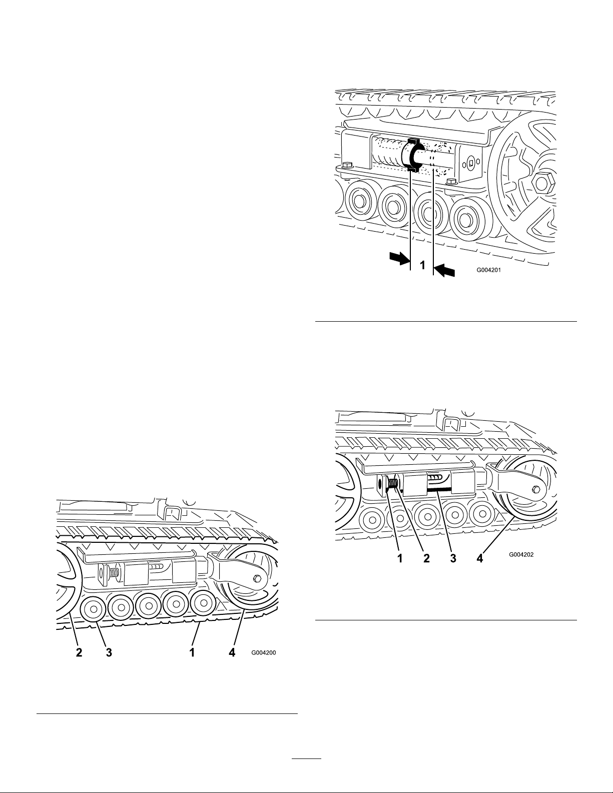
AdjustingtheTrackTension
Thereshouldbe7cm(2-3/4inches)betweenthetensionnut
andthebackofthetensiontube(Figure47).Ifnot,adjust
thetracktensionusingthefollowingprocedure:
Figure47
1.7cm(2-3/4inches)
3.Usingawaterhoseorpressurewasher,removedirt
fromeachtracksystem.
Important:Ensurethatyouusehigh-pressurewaterto
washonlythetrackarea.Donotuseahigh-pressure
washertocleantherestofthetractionunit.Donot
usehighpressurewaterbetweenthedrivesprocket
andthetractionunitoryoumaydamagethemotor
seals.High-pressurewashingcandamagetheelectrical
systemandhydraulicvalvesordepletegrease.
Important:Ensurethatyoufullycleantheroadwheels,
thetensionwheel,andthedrivesprocket(Figure46).
Theroadwheelsshouldrotatefreelywhenclean.
1.Lowertheloaderarms,shutofftheengine,andremove
thekey.
2.Lift/supportthesideoftheunittobeworkedonso
thatthetrackisofftheground.
3.Removethelockingboltandnut(Figure48).
Figure48
1.Lockingbolt3.T ensiontube
2.Tensioningscrew4.Tensionwheel
Figure46
1.Track3.Roadwheels
2.Drivesprocket4.Tensionwheel
4.Usinga1/2inchdrivesocket(Figure49),turnthe
tensioningscrewcounter-clockwiseuntilthedistance
betweenthetensionnutandthebackofthetension
tube(Figure47)is7cm(2-3/4inches).
5.Aligntheclosestnotchinthetensionscrewtothe
lockingboltholeandsecurethescrewwiththelocking
boltandnut(Figure48).
6.Lowerthetractionunittotheground.
37
Page 38
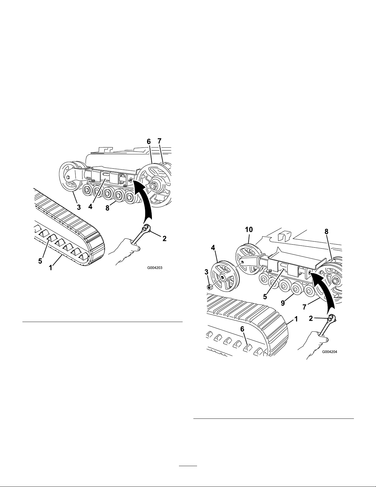
ReplacingtheTracks
Model22323
Whenthetracksarebadlyworn,replacethem.
1.Lowertheloaderarms,shutofftheengine,andremove
thekey.
2.Lift/supportthesideoftheunittobeworkedonso
thatthetrackis7.6to10cm(3to4inches)offthe
ground.
3.Removethelockingboltandnut(Figure48).
4.Usinga1/2inchdrivesocket,releasethedrivetension
byturningthetensioningscrewclockwise(Figure48
andFigure49).
10.Startingatthebottomofthetensionwheel,installthe
trackaroundthewheelbyrotatingthetrackrearward
whilepushingthelugsintothewheel.
11.Turnthetensioningscrewcounter-clockwiseuntilthe
distancebetweenthetensionnutandthebackofthe
forktube(Figure47)is7cm(2-3/4inches).
12.Aligntheclosestnotchinthetensionscrewtothe
lockingboltholeandsecurethescrewwiththelocking
boltandnut.
13.Lowerthetractionunittotheground.
14.Repeatsteps2through13toreplacetheothertrack.
Model22324
Whenthetracksarebadlyworn,replacethem.
1.Lowertheloaderarms,shutofftheengine,andremove
thekey.
2.Lift/supportthesideoftheunittobeworkedonso
thatthetrackis7.6to10cm(3to4inches)offthe
ground.
3.Removethelockingboltandnut(Figure48).
Figure49
1.Track5.Tracklug
2.1/2inchsocket
3.Tensionwheel
4.Forktube8.Roadwheels
6.Drivesprocket
7.Sprocketspacer
5.Pushthetensionwheeltowardtherearoftheunit
tomovetheforktubeagainsttheframe(Figure49).
(Ifitdoesnottouchtheframe,continueturningthe
tensioningscrewuntilitdoes.)
6.Beginremovingthetrackatthetopofthetension
wheel,peelingitoffthewheelwhilerotatingthetrack
forward.
7.Whenthetrackisoffthetensionwheel,removeitfrom
thedrivesprocketandroadwheels(Figure49).
8.Beginningatthedrivesprocket,coilthenewtrack
aroundthesprocket,ensuringthatthelugsonthetrack
tbetweenthespacersonthesprocket(Figure49).
9.Pushthetrackunderandbetweentheroadwheels
(Figure49).
4.Usinga1/2inchdrivesocket,releasethedrivetension
byturningthetensioningscrewclockwise(Figure48
andFigure50).
Figure50
1.Track6.Tracklug
2.1/2inchsocket
3.Tensionwheelnut
4.Outertensionwheel
5.Forktube10.Innertensionwheel
7.Drivesprocket
8.Sprocketspacer
9.Roadwheels
5.Pushthetensionwheeltowardtherearoftheunitto
movethetensiontubeagainsttheframe(Figure50).
38
Page 39
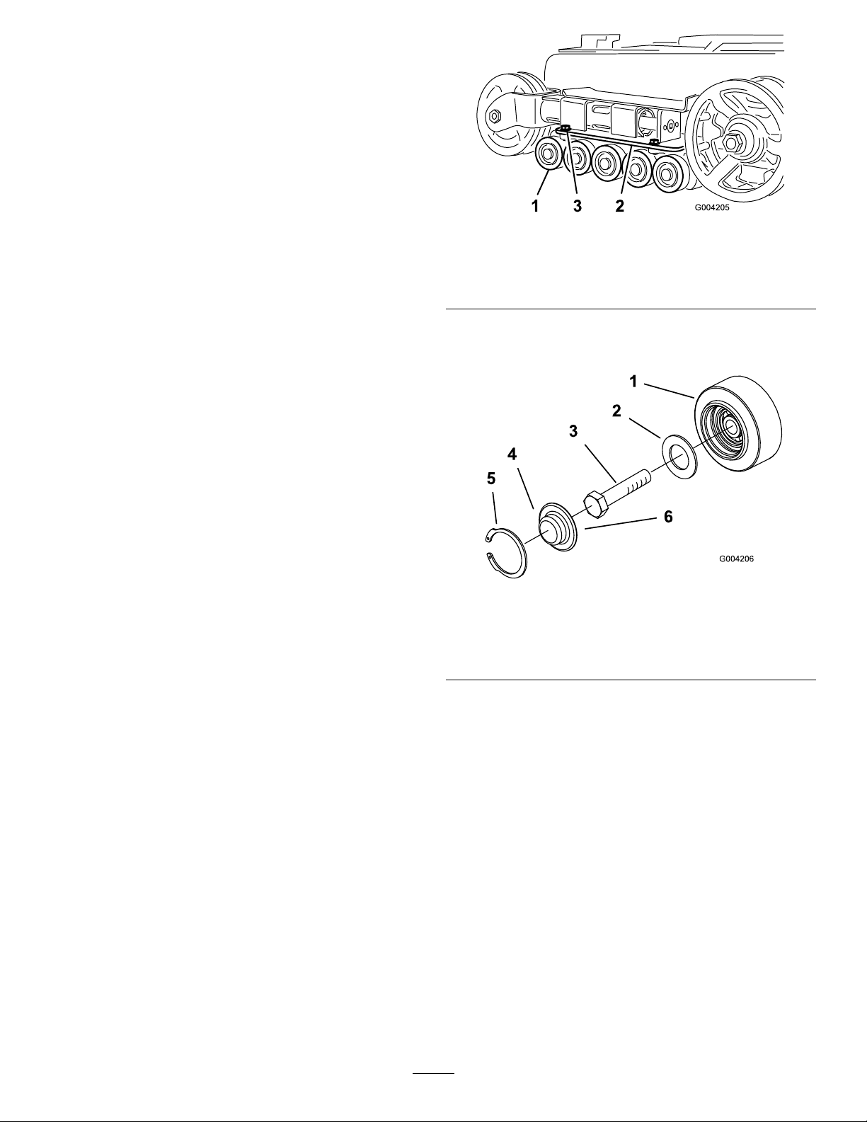
(Ifitdoesnottouchtheframe,continueturningthe
tensioningscrewuntilitdoes.)
6.Removethenutsecuringtheoutertensionwheeland
removethewheel(Figure50).
7.Removethetrack(Figure50).
8.Removethenutsecuringtheinnertensionwheeland
removethewheel(Figure50).
9.Pullthe4largewashersoutofthe2wheels,1oneach
sideofeachwheel.
10.Cleantheoldgreaseanddirtoutoftheareabetween
wherethewasherswereinstalledandthebearings
insidethewheels,thenllthisareaoneachsideof
eachwheelwithgrease.
1.Roadwheels
2.Lowertrackguide
Figure51
3.Trackguidebolts(only2
shown)
11.Installthelargewashersonthewheelsoverthegrease.
12.Installtheinnertensionwheelandsecureitwiththe
nutremovedpreviously(Figure50).
13.Torquethenutto407N∙m(300ft-lb).
14.Installthenewtrack,ensuringthatthelugsinthe
tracktbetweenthespacersinthemiddleofthedrive
sprocket(Figure50).
15.Installtheoutertensionwheelandsecureitwiththe
nutremovedpreviously(Figure50).
16.Torquethenutto407N∙m(300ft-lb).
17.Turnthetensioningscrewcounter-clockwiseuntilthe
distancebetweenthetensionnutandthebackofthe
tensiontube(Figure47)is7cm(2-3/4inches).
18.Aligntheclosestnotchinthetensionscrewtothe
lockingboltholeandsecurethescrewwiththelocking
boltandnut.
19.Repeatsteps2through18toreplacetheothertrack.
20.Lowerthetractionunittotheground.
MaintainingtheRoadWheels
1.Removethetracks;refertoReplacingtheTracks(page
38).
2.Removethe4boltssecuringeachlowertrackguide
whichcontainstheroadwheels,andremovethem
(Figure51).
3.Removethesnapringandcapfromaroadwheel
(Figure52).
Figure52
1.Roadwheel4.Roadwheelcap
2.Gasket5.Snapring
3.Bolt6.Addgreaseunderthecap
4.Checkthegreaseunderthecapandaroundthegasket
(Figure52).Ifitisdirty,gritty,ordepleted,cleanoutall
ofthegrease,replacethegasket,andaddnewgrease.
5.Ensurethattheroadwheelturnssmoothlyonthe
bearing.Ifitisfrozen,replacetheroadwheelas
describedintheRoadWheelKitInstallationInstructionsor
contactyourAuthorizedServiceDealerforrepair.
6.Placethegreasedroadwheelcapoverthebolthead
(Figure52).
7.Securetheroadwheelcapwiththesnapring(Figure
52).
8.Repeatsteps3through7fortheotherroadwheels.
9.Installeachtrackguidetothetractionunitframeusing
thefastenersyouremovedpreviously.Torquethebolts
to91to112N∙m(67to83ft-lb).
10.Installthetracks;refertoModel22323(page38)or
Model22324(page38).
39
Page 40

CoolingSystem
Maintenance
ServicingtheCoolingSystem
CleaningtheRadiatorScreen
Beforeeachuse,checkandcleantheradiatorscreen,located
behindthegrillatthefrontofthetractionunit.Remove
anybuild-upofgrass,dirtorotherdebrisfromtheradiator
screenwithcompressedair.
ServiceInterval:Beforeeachuseordaily—Cleanthe
radiator.
Every100hours—Checkthecoolingsystemhoses.
Yearly—Changetheenginecoolant(Authorized
ServiceDealeronly).
DANGER
Iftheenginehasbeenrunning,thepressurized,hot
coolantcanescapeandcausesevereburns.
•Donotremovetheradiatorcapwhentheengine
ishot.Alwaysallowtheenginetocoolatleast
15minutesoruntiltheradiatorcapiscool
enoughtotouchwithoutburningyourhand
beforeremovingtheradiatorcap.
•Donottouchradiatorandsurroundingparts
thatarehot.
•Usearagwhenopeningtheradiatorcap,and
openthecapslowlytoallowsteamtoescape.
ChangingtheEngineCoolant
HaveanAuthorizedServiceDealerchangetheenginecoolant
yearly.
Ifyouneedtoaddenginecoolant,refertoChecking,Adding,
andBleedingtheEngineCoolant(page20).
DANGER
Rotatingshaftandfancancausepersonalinjury.
•Donotoperatethemachinewithoutthecovers
inplace.
•Keepngers,handsandclothingclearof
rotatingfananddriveshaft.
•Shutofftheengineandremovetheignitionkey
beforeperformingmaintenance.
CAUTION
Swallowingenginecoolantcancausepoisoning.
•Donotswallowenginecoolant.
•Keepoutofreachfromchildrenandpets.
40
Page 41
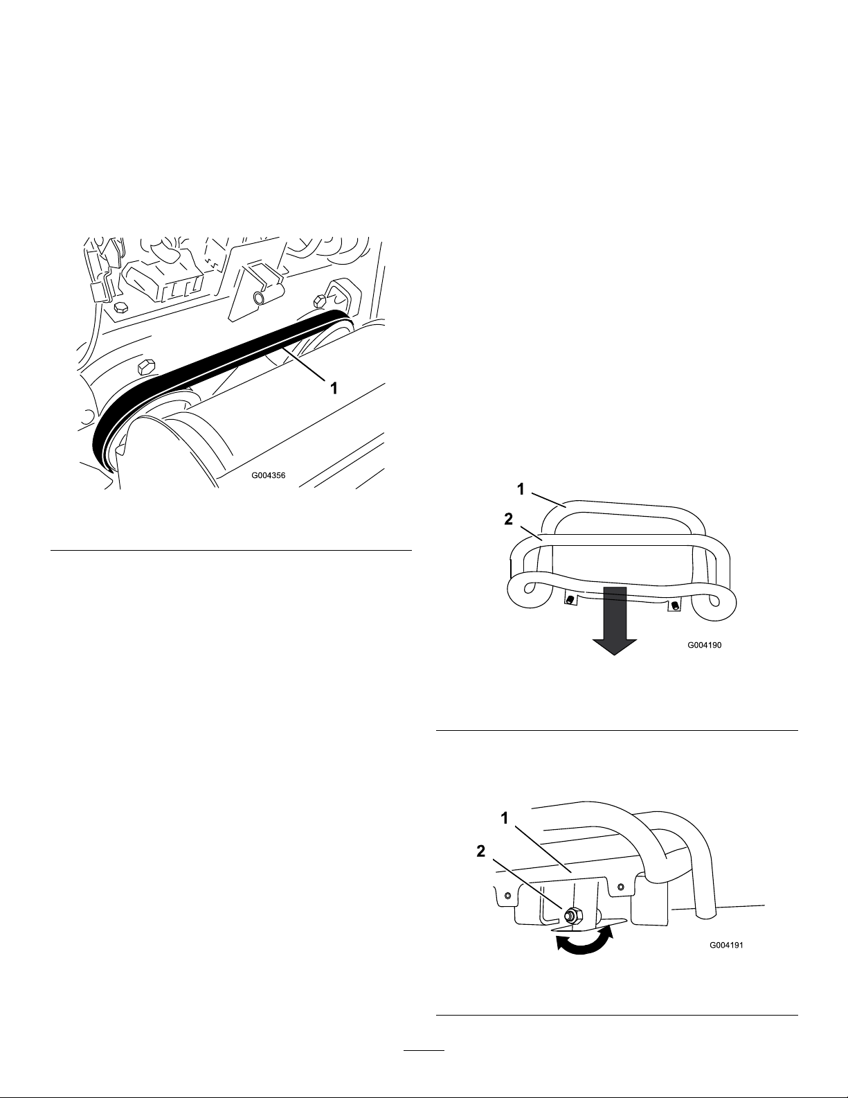
BeltMaintenance
CheckingtheConditionofthe HydraulicPumpBelt
ServiceInterval:Yearly
Checktheconditionofthehydraulicpumpbelt(Figure53)
yearly.HaveanAuthorizedServiceDealerreplaceitifit
becomesdamagedorworn.
ControlsSystem
Maintenance
Thefactoryadjuststhecontrolsbeforeshippingthetraction
unit.However,aftermanyhoursofuse,youmayneedto
adjustthetractioncontrolalignment,theneutralpositionof
thetractioncontrol,andthetrackingofthetractioncontrol
inthefullforwardposition.
Important:Toadjustthecontrolsproperly,complete
eachprocedureintheorderlisted.
AdjustingtheTractionControl Alignment
Ifthetractioncontrolbardoesnotrestushandsquare
withthereferencebarwheninthefullbackwardposition,
immediatelycompletethefollowingprocedure:
1.Parkthetractionunitonaatsurfaceandlowerthe
loaderarm.
2.Shutofftheengineandremovethekey.
3.Pullstraightbackonthetractioncontrolsothefront
ofthecontrolcontactsthereferencebar(Figure54).
Figure53
1.Hydraulicpumpbelt
CheckingtheAlternator/Fan BeltTension
ServiceInterval:Every100hours—Checkthealternator/fan
belttension(refertotheengineowner’ s
manualforinstructions).
Every500hours—Replacethealternator/fanbelt
(refertotheengineowner’ smanualforinstructions).
Figure54
1.Frontofthecontrol(outof
alignment)
4.Ifthefrontofthetractioncontroldoesnotrestsquare
andushwiththereferencebar,loosentheangenut
andboltinthestemofthetractioncontrol(Figure55).
2.Referencebar
Figure55
1.Tractioncontrol
41
2.Stem,bolt,andnut
Page 42

5.Adjustthetractioncontrolsothatitrestsushagainst
g013014
1
2
thereferencebarwhenyoupullitstraightback(Figure
55andFigure56).
Figure56
WARNING
Whenthetractionunitisrunning,youcould
becaughtandinjuredinmovingpartsor
burnedonhotsurfaces.
Stayawayfrompinchpoints,movingparts,
andhotsurfaceswhenadjustingtherunning
tractionunit.
5.Ifthelefttrackmoves,lengthenorshortentheright
tractionroduntilthetrackstopsmoving.
6.Iftherighttrackmoves,lengthenorshortentheleft
tractionroduntilthetrackstopsmoving.
6.Tightentheangenutandboltinthetractioncontrol
stem.
AdjustingtheTractionControl NeutralPosition
Ifthetractionunitcreepsforwardorbackwardwhenthe
tractioncontrolisinneutralandtheunitiswarm,immediately
completethefollowingprocedure:
1.Lift/supportthetractionunitsothatbothtracksare
offtheground.
2.Opentherearaccesscover.
3.Loosenthejamnutsonthetractionrods,underthe
controlpanel(Figure57).
7.Tightenthejamnuts.
8.Closetherearaccesscover.
9.Shutofftheengineandlowerthetractionunittothe
ground.
10.Drivethetractionunitinfullreverse,checkingto
seeiftheunittracksstraight.Ifitdoesnot,notethe
directionthetractionunitveers.Repeattheadjustment
previouslydescribedsothatittracksstraightinreverse.
Figure57
1.Tractionrod2.Jamnut
4.Startthetractionunitandsetthethrottletoabout1/3
openposition.
42
Page 43
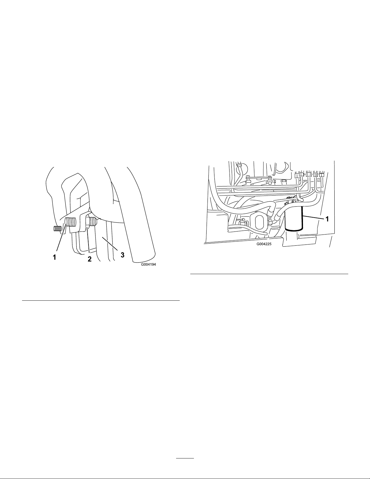
AdjustingtheTrackingofthe TractionControl,FullForward Position
HydraulicSystem
Maintenance
Ifthetractionunitdoesnotdrivestraightwhenyouhold
thetractioncontrolagainstthereferencebar,completethe
followingprocedure:
1.Drivethetractionunitwiththetractioncontrolagainst
thereferencebar,notingwhichdirectionthetraction
unitveers.
2.Releasethetractioncontrol.
3.Ifthetractionunitveerstotheleft,loosentheright
jamnutandadjustthetrackingsetscrewonthefront
ofthetractioncontrol(Figure58).
4.Ifthetractionunitveerstotheright,loosentheleft
jamnutandadjustthetrackingsetscrewonthefront
ofthetractioncontrol(Figure58).
ReplacingtheHydraulicFilter
ServiceInterval:Aftertherst8hours
Every200hours
Important:Donotsubstituteanautomotiveoillteror
severehydraulicsystemdamagemayresult.
1.Positiontractionunitonalevelsurface.
2.Lowertheloaderarms,shutofftheengine,andremove
thekey.
3.Opentherearaccesscover.
4.Placeadrainpanunderthelter(Figure59).
Figure58
1.Setscrew3.Stop
2.Jamnut
5.Repeatsteps1through4untilthetractionunitdrives
straightinthefullforwardposition.
Important:Ensurethatthetrackingsetscrews
touchthestopsinthefullforwardpositiontoavoid
overstrokingthehydraulicpumps.
Figure59
1.Hydrauliclter
5.Removetheoldlter(Figure59)andwipethesurface
ofthelteradaptergasketclean.
6.Applyathincoathydraulicuidtotherubbergasket
onthereplacementlter.
7.Installthereplacementhydrauliclterontothelter
adapter(Figure59).Tightenitclockwiseuntilthe
rubbergasketcontactsthelteradapter,thentighten
thelteranadditional3/4turn.
8.Cleanupanyspilleduid.
9.Starttheengineandletitrunforabout2minutesto
purgeairfromthesystem.
10.Shutofftheengineandcheckforleaks.
43
Page 44

WARNING
Hydraulicuidescapingunderpressurecan
penetrateskinandcauseinjury.Fluidinjected
intotheskinmustbesurgicallyremoved
withinafewhoursbyadoctorfamiliarwith
thisformofinjury;otherwisegangrenemay
result.
•Keepyourbodyandhandsawayfrom
pinholeleaksornozzlesthateject
high-pressurehydraulicuid.
•Usecardboardorpapertondhydraulic
leaks;neveruseyourhands.
11.Checktheuidlevelinthehydraulictank;referto
CheckingtheHydraulicFluidLevel(page19)andadd
uidtoraisetheleveltomarkondipstick.Donot
overllthetank.
IndustryStandards
APIGL-4,AGCOPoweruid821XL,FordNewHolland
FNHA-2-C-201.00,KubotaUDT ,JohnDeereJ20C,Vickers
35VQ25andVolvoWB-101/BM.
Note:Manyhydraulicuidsarealmostcolorless,making
itdifculttospotleaks.Areddyeadditiveforthe
hydraulicsystemoilisavailablein20ml(2/3oz)bottles.
Onebottleissufcientfor15to22L(4-6USgallons)
ofhydraulicoil.OrderPartNo.44-2500fromyour
AuthorizedT oroDealer.
1.Positionthetractionunitonalevelsurface.
2.Openthehood.
3.Installthecylinderlock,shutofftheengine,and
removethekey .
4.Allowthetractionunittocoolcompletely.
5.Removethehydraulic-tankcapanddipstick(Figure60).
12.Closetherearaccesscover.
ChangingtheHydraulicFluid
ServiceInterval:Every400hours/Y early(whichevercomes
rst)
HydraulicFluidSpecication:
Useonly1ofthefollowinguidsinthehydraulicsystem:
•ToroPremiumTransmission/HydraulicTractor
Fluid(refertoyourAuthorizedT oroDealerformore
information)
•ToroPremiumAllSeasonHydraulicFluid(referto
yourAuthorizedToroDealerformoreinformation)
•IfeitheroftheaboveTorouidsarenotavailable,
youmayuseanotherUniversalTractorHydraulic
Fluid(UTHF),buttheymustbeonlyconventional,
petrolium-basedproducts.Thespecicationsmustfall
withinthelistedrangeforallofthefollowingmaterial
propertiesandtheuidshouldmeetthelistedindustry
standards.Checkwithyouroilsuppliertodetermineif
theoilmeetsthesespecications.
Note:Torodoesnotassumeresponsibilityfordamage
causedbyimpropersubstitutions,souseonlyproducts
fromreputablemanufacturerswhostandbehindtheir
recommendations.
Note:Thellercapisbehindthefrontscreen.Ifyou
wanttoimproveyouraccesstoit,removethescreen.
Figure60
1.Fillerneck2.Dipstick
6.Placealargedrainpain(capableofholding15US
gallons)underthedrainplugonthefrontofthe
tractionunit(Figure61).
MaterialProperties
cStat40degreesC:55to62 Viscosity,ASTMD445
cStat100degreesC:9.1to
9.8
Viscosityindex,ASTMD2270
PourPoint,ASTMD97-35to-46degreesF(-37to
140to152
-43degreesC)
44
Page 45

1.Drainplug
Figure61
CheckingtheHydraulicLines
ServiceInterval:Every100hours—Checkthehydraulic
linesforleaks,loosettings,kinkedlines,
loosemountingsupports,wear,weather,
andchemicaldeterioration.(Make
necessaryrepairsbeforeoperating.)
Every1,500hours/Every2years(whichevercomes
rst)—Replaceallmovinghydraulichoses.
WARNING
Hydraulicuidescapingunderpressurecan
penetrateskinandcauseinjury.Fluidinjectedinto
theskinmustbesurgicallyremovedwithinafew
hoursbyadoctorfamiliarwiththisformofinjury
otherwisegangrenemayresult.
•Keepyourbodyandhandsawayfrompinhole
leaksornozzlesthatejecthigh-pressure
hydraulicuid.
7.Removethedrainplugandallowtheoiltodraininto
thepan(Figure61).
8.Whennished,installandtightenthedrainplug.
Note:Disposeoftheusedoilatacertiedrecycling
center.
9.Fillthehydraulictankwithapproximately45L(12US
gallons)ofhydraulicuidasspeciedpreviously;refer
toChangingtheHydraulicFluid(page44).
10.Starttheengineandletitrunforafewminutes.
11.Shutofftheengine.
12.Checkthehydraulicuidlevelandtopitoffif
necessary;refertoChangingtheHydraulicFluid(page
44).
13.Closethehood.
•Usecardboardorpapertondhydraulicleaks;
neveruseyourhands.
45
Page 46

Cleaning
RemovingDebrisfromthe
Storage
1.Lowertheloaderarms,shutofftheengine,andremove
thekey.
TractionUnit
ServiceInterval:Beforeeachuseordaily
Important:Operatingtheenginewithblockedscreens
and/orcoolingshroudsremovedwillresultinengine
damagefromoverheating.
1.Parkthetractionunitonalevelsurface,lowerthe
loaderarms,andshutofftheengine.
2.Removethekeyandallowtheenginetocool.
3.Openthehood.
4.Cleananydebrisfromthefrontandsidescreens.
5.Wipeawaydebrisfromtheaircleaner.
6.Cleananydebrisbuildupontheengineandintheoil
coolernswithabrushorblower.
Important:Itispreferabletoblowdirtout,rather
thanwashingitout.Ifwaterisused,keepitaway
fromelectricalitemsandhydraulicvalves.Do
notuseahigh-pressurewasher.High-pressure
washingcandamagetheelectricalsystemand
hydraulicvalvesordepletegrease.
7.Cleandebrisfromthehoodopening,mufer,andheat
shields.
8.Closethehood.
2.Removedirtandgrimefromtheentiretractionunit.
Important:Youcanwashthetractionunitwith
milddetergentandwater.Donotpressurewash
thetractionunit.Avoidexcessiveuseofwater,
especiallynearthecontrolpanel,engine,hydraulic
pumps,andmotors.
3.Servicetheaircleaner;refertoServicingtheAir
Cleaner(page30).
4.Greasethetractionunit;refertoGreasingtheTraction
Unit(page30).
5.Changethecrankcaseoil;refertoServicingtheEngine
Oil(page31).
6.Chargethebattery;refertoChargingtheBattery(page
35).
7.Checkandadjustthetracktension;refertoAdjusting
theTrackTension(page37).
8.Checkandtightenallbolts,nuts,andscrews.Repairor
replaceanypartthatisdamaged.
9.Paintallscratchedorbaremetalsurfaces.Paintis
availablefromyourAuthorizedServiceDealer.
10.Storethetractionunitinaclean,drygarageorstorage
area.Removethekeyfromtheignitionswitchand
keepitinamemorableplace.
11.Coverthetractionunittoprotectitandkeepitclean.
CleaningtheChassis
ServiceInterval:Every100hours—Checkfordirtbuild-up
inthechassis.
Usingaashlight,openthehoodandinspecttheareaunder
theengineonaregularbasis.Whenthedebrisis1to2inches
deep,haveanAuthorizedServiceDealerremovetherearof
thetractionunit,fueltank,andbatteryandushthechassis
clean.
46
Page 47

Troubleshooting
Problem
Thestarterdoesnotcrank.
Theenginecranksbutdoesnotstart.
PossibleCauseCorrectiveAction
1.Theelectricalconnectionsare
corrodedorloose.
2.Afuseisblownorloose.2.Correctorreplacethefuse.
3.Thebatteryisdischarged.
4.Therelayorswitchisdamaged.
5.Astarterorstartersolenoidis
damaged.
6.Internalenginecomponentshave
seized.
1.Thestartingprocedureisincorrect.1.Usethecorrectstartingprocedure.
2.Thefueltankisempty.2.Fillthetankwithfreshfuel.
3.Thefuel-shutoffvalveisclosed.3.Openthefuel-shutoffvalve.
4.Dirt,water,stalefuel,orincorrectfuel
isinthefuelsystem.
5.Thefuellineisclogged.5.Cleanorreplacethefuelline.
6.Thereisairinthefuel.6.Bleedthenozzlesandcheckforair
7.Theglowplugsareinoperative.
8.Thecrankingspeedisslow.
9.Theair-cleanerltersaredirty .9.Servicetheairlters.
10.Thefuellterisclogged.10.Replacethefuellter.
11.Improperfuelgradeforcoldweatheris
usedinthemachine.
12.Thereislowcompression.
13.Theinjectionnozzlesaredamaged.
14.Theinjectionpumptimingisincorrect.
15.Theinjectionpumpisbroken.
16.TheETRsolenoidisbroken.
1.Checktheelectricalconnectionsfor
goodcontact.
3.Chargethebatteryorreplaceit.
4.ContactyourAuthorizedService
Dealer.
5.ContactyourAuthorizedService
Dealer.
6.ContactyourAuthorizedService
Dealer.
4.Drainandushthefuelsystem;add
freshfuel.
leaksatthefuelhoseconnections
andttingsbetweenthefueltankand
engine.
7.Checkthefuse,glowplugs,andwiring.
8.Checkthebattery,oilviscosity,and
startingmotor(contactyourAuthorized
ServiceDealer).
11.Drainthefuelsystemandreplace
thefuellter.Addfreshfuelof
propergradeforambienttemperature
conditions.Youmayneedtowarmthe
entiretractionunit.
12.ContactyourAuthorizedService
Dealer.
13.ContactyourAuthorizedService
Dealer.
14.ContactyourAuthorizedService
Dealer.
15.ContactyourAuthorizedService
Dealer.
16.ContactyourAuthorizedService
Dealer.
47
Page 48

Problem
PossibleCauseCorrectiveAction
Theenginestartsbutdoesnotkeep
running.
Theenginerunsbutknocksormisses.
1.Thefuel-tankventisrestricted.1.Loosenthecap.Iftheenginerunswith
2.Dirtorwaterisinthefuelsystem.2.Drainandushthefuelsystem;add
3.Thefuellterisclogged.3.Replacethefuellter.
4.Thereisairinthefuel.4.Bleedthenozzlesandcheckforair
5.Improperfuelgradeforcoldweather
wasusedinthemachine.
6.Thespark-arrestorscreenisclogged.
7.Thefuelpumpisdamaged.7.ContactyourAuthorizedService
1.Dirt,water,stalefuel,orincorrectfuel
isinthefuelsystem.
2.Theengineisoverheating.
3.Thereisairinthefuel.3.Bleednozzlesandcheckforairleaksat
4.Theinjectionnozzlesaredamaged.
5.Thereislowcompression
6.Theinjection-pumptimingisincorrect.
7.Thereisexcessivecarbonbuildup.
8.Thereisinternalwearordamage.
thecaploosened,replacethecap.
freshfuel.
leaksatfuelhoseconnectionsand
ttingsbetweenthefueltankand
engine.
5.Drainthefuelsystemandreplace
thefuellter.Addfreshfuelof
propergradeforambienttemperature
conditions.
6.Cleanorreplacethespark-arrestor
screen.
Dealer.
1.Drainandushthefuelsystem;add
freshfuel.
2.Referto“Theengineoverheats.”
thefuelhoseconnectionsandttings
betweenthefueltankandengine.
4.ContactyourAuthorizedService
Dealer.
5.ContactyourAuthorizedService
Dealer.
6.ContactyourAuthorizedService
Dealer.
7.ContactyourAuthorizedService
Dealer.
8.ContactyourAuthorizedService
Dealer.
Theenginedoesnotidle.
1.Thefuel-tankventisrestricted.1.Loosenthecap.Iftheenginerunswith
2.Dirt,water,stalefuel,orincorrectfuel
isinthefuelsystem.
3.Theair-cleanerltersaredirty .3.Servicetheairlters.
4.Thefuellterisclogged.4.Replacethefuellter.
5.Thereisairinthefuel.5.Bleedthenozzlesandcheckforair
6.Thefuelpumpisdamaged.6.ContactyourAuthorizedService
7.Thereislowcompression
thecaploosened,replacethecap.
2.Drainandushthefuelsystem;add
freshfuel.
leaksatfuelhoseconnectionsand
ttingsbetweenthefueltankand
engine.
Dealer.
7.ContactyourAuthorizedService
Dealer.
48
Page 49

Problem
PossibleCauseCorrectiveAction
Theengineoverheats.
Exhaustproducesexcessiveblacksmoke.
1.Morecoolantisneeded.
2.Restrictedairowtotheradiator.
3.Thecrankcase-oillevelisincorrect.3.FillordraintotheFullmark.
4.Theloadisexcessive.4.Reduceload;uselowergroundspeed.
5.Incorrectfuelisinthefuelsystem.5.Drainandushthefuelsystem;add
6.Thethermostatisdamaged.
7.Thefanbeltisbroken.7.ContactyourAuthorizedService
8.Injectiontimingisincorrect.
9.Coolantpumpisdamaged.9.ContactyourAuthorizedService
1.Theloadisexcessive.1.Reduceload;uselowergroundspeed.
2.Theair-cleanerltersaredirty .2.Servicetheairlters.
3.Incorrectfuelisinthefuelsystem.3.Drainthefuelsystemandrellwith
4.Theinjection-pumptimingisincorrect.
5.Theinjectionpumpisdamaged.
6.Theinjectionnozzlesaredamaged.
1.Checkandaddcoolant.
2.Inspectandcleantheradiatorscreen
witheveryuse.
freshfuel.
6.ContactyourAuthorizedService
Dealer.
Dealer.
8.ContactyourAuthorizedService
Dealer.
Dealer.
speciedfuel.
4.ContactyourAuthorizedService
Dealer.
5.ContactyourAuthorizedService
Dealer.
6.ContactyourAuthorizedService
Dealer.
Exhaustproducesexcessivewhitesmoke.
Theenginelosespower.
1.ThekeywasturnedtotheSTART
positionbeforetheglow-pluglight
turnedoff.
2.Theenginetemperatureislow.
3.Theglowplugsareinoperative.
4.Theinjectionpumptimingisincorrect.
5.Theinjectionnozzlesaredamaged.
6.Thereislowcompression.
1.Theengineloadisexcessive.1.Reducethegroundspeed.
2.Thecrankcase-oillevelisincorrect.2.FillordraintotheFullmark.
3.Theair-cleanerltersaredirty .3.Servicetheairlters.
4.Dirt,water,stalefuel,orincorrectfuel
isinthefuelsystem.
5.Theengineisoverheating.
6.Thespark-arrestorscreenisclogged.
7.Thereisairinthefuel.7.Bleedthenozzlesandcheckforair
8.Thereislowcompression
9.Thefuel-tankventisrestricted.9.ContactyourAuthorizedService
10.Theinjection-pumptimingisincorrect.
11.Theinjectionpumpisdamaged.
1.TurnthekeytotheRUNpositionand
allowtheglow-pluglighttoturnoff
beforestartingtheengine.
2.Checkthethermostat.
3.Checkthefuse,glowplugsandwiring.
4.ContactyourAuthorizedService
Dealer.
5.ContactyourAuthorizedService
Dealer.
6.ContactyourAuthorizedService
Dealer.
4.Drainandushthefuelsystem;add
freshfuel.
5.Referto“Theengineoverheats.”
6.Cleanorreplacethespark-arrestor
screen.
leaksatfuelhoseconnectionsand
ttingsbetweenthefueltankand
engine.
8.ContactyourAuthorizedService
Dealer.
Dealer.
10.ContactyourAuthorizedService
Dealer.
11.ContactyourAuthorizedService
Dealer.
49
Page 50

Problem
PossibleCauseCorrectiveAction
Thetractionunitdoesnotdrive.
1.Theparkingbrakeison.1.Releasetheparkingbrake.
2.Thehydraulicuidlevelislow.2.Addhydraulicuidtothereservoir.
3.Thetowvalvesareopen.
4.Thepumpand/orwheelmotoris
damaged.
5.Thereliefvalveisdamaged.5.ContactyourAuthorizedService
3.Closethetowvalves.
4.ContactyourAuthorizedService
Dealer.
Dealer.
50
Page 51
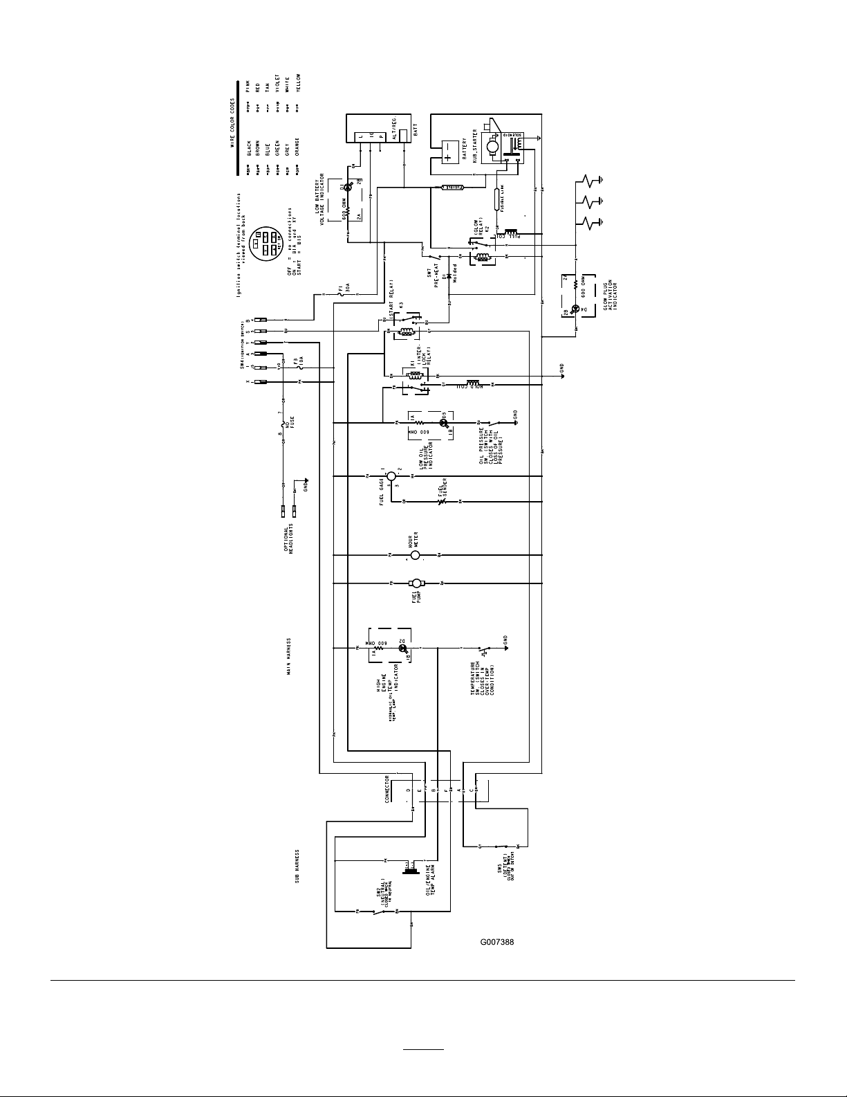
Schematics
G007388
ElectricalSchematic(Rev .B)
51
Page 52
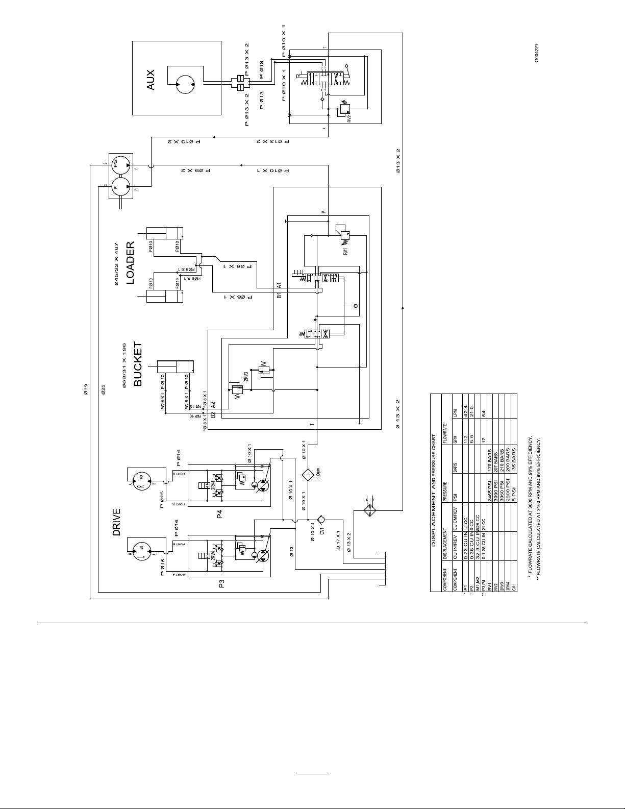
HydraulicSchematic(Rev .A)
52
Page 53

Notes:
Page 54

Notes:
Page 55

InternationalDistributorList
Distributor:
AgrolancKft
AsianAmericanIndustrial(AAI)
B-RayCorporation
BrisaGoodsLLC
CascoSalesCompany
CeresS.A.CostaRica
CSSCTurfEquipment(pvt)Ltd.SriLanka
CyrilJohnston&Co.
CyrilJohnston&Co.RepublicofIreland
FatDragon
FemcoS.A.Guatemala
FIVEMANSNew-T echCo.,LtdChina
ForGarderOU
G.Y .K.CompanyLtd.
GeomechanikiofAthensGreece
GolfinternationalTurizm
HakoGroundandGardenSweden
HakoGroundandGarden
HayterLimited(U.K.)
HydroturfInt.CoDubai
HydroturfEgyptLLC
IrrimacPortugal351212388260T oroEuropeNVBelgium3214562960
IrrigationProductsInt'lPvtLtd.India00914424494387ValtechMorocco212537663636
JeanHeybroekb.v.Netherlands31306394611VictusEmakPoland48618238369
Country:
Hungary3627539640
HongKong85224977804
Korea82325512076
Mexico12104952417
PuertoRico7877888383
NorthernIreland442890813121
China
Estonia3723846060
Japan81726325861Riversa
Turkey902163365993
Norway4722907760
UnitedKingdom441279723444
UnitedArabEmirates97143479479T-MarktLogisticsLtd.Hungary3626525500
Egypt2025194308ToroAustraliaAustralia61395807355
PhoneNumber:Distributor:
MaquiverS.A.Colombia
MaruyamaMfg.Co.Inc.
Mountelda.s.CzechRepublic
Mountelda.s.Slovakia
5062391138
941 12746100
442890813121ParklandProductsLtd.NewZealand6433493760
8861080841322
5024423277
86-10-63816136
30109350054
4635100000
MunditolS.A.
NormaGarden
OslingerTurfEquipmentSA
OyHakoGroundandGardenAb
Perfetto
PratoverdeSRL.
Prochaska&Cie
RTCohen2004Ltd.
LelyTurfcare
Lely(U.K.)Limited
SolvertS.A.S.
SpyprosStavrinidesLimitedCyprus
SurgeSystemsIndiaLimited
Country:
Japan81332522285
Argentina541 148219999
Russia74954116120
Ecuador59342396970
Finland35898700733
Poland48618208416
Italy390499128128
Austria4312785100
Israel97298617979
Spain
Denmark4566109200
UnitedKingdom441480226800
France33130817700
India911292299901
PhoneNumber:
5712364079
420255704220
420255704220
34952837500
35722434131
EuropeanPrivacyNotice
TheInformationToroCollects
ToroWarrantyCompany(Toro)respectsyourprivacy .Inordertoprocessyourwarrantyclaimandcontactyouintheeventofaproductrecall,weaskyou
tosharecertainpersonalinformationwithus,eitherdirectlyorthroughyourlocalTorocompanyordealer.
TheT orowarrantysystemishostedonserverslocatedwithintheUnitedStateswhereprivacylawmaynotprovidethesameprotectionasapplies
inyourcountry .
BYSHARINGYOURPERSONALINFORMATIONWITHUS,YOUARECONSENTINGTOTHEPROCESSINGOFYOURPERSONALINFORMATION
ASDESCRIBEDINTHISPRIV ACYNOTICE.
TheWayT oroUsesInformation
Toromayuseyourpersonalinformationtoprocesswarrantyclaims,tocontactyouintheeventofaproductrecallandforanyotherpurposewhichwetell
youabout.T oromayshareyourinformationwithT oro'safliates,dealersorotherbusinesspartnersinconnectionwithanyoftheseactivities.Wewillnot
sellyourpersonalinformationtoanyothercompany .Wereservetherighttodisclosepersonalinformationinordertocomplywithapplicablelawsand
withrequestsbytheappropriateauthorities,tooperateoursystemsproperlyorforourownprotectionorthatofotherusers.
RetentionofyourPersonalInformation
Wewillkeepyourpersonalinformationaslongasweneeditforthepurposesforwhichitwasoriginallycollectedorforotherlegitimatepurposes
(suchasregulatorycompliance),orasrequiredbyapplicablelaw.
Toro'sCommitmenttoSecurityofY ourPersonalInformation
Wetakereasonableprecautionsinordertoprotectthesecurityofyourpersonalinformation.Wealsotakestepstomaintaintheaccuracyandcurrent
statusofpersonalinformation.
AccessandCorrectionofyourPersonalInformation
Ifyouwouldliketorevieworcorrectyourpersonalinformation,pleasecontactusbyemailatlegal@toro.com.
AustralianConsumerLaw
AustraliancustomerswillnddetailsrelatingtotheAustralianConsumerLaweitherinsidetheboxoratyourlocalT oroDealer.
374-0269RevK
Page 56

TheToroWarranty
AOne-Y earLimitedWarranty
CompactUtilityEquipment
(CUE)Products
ConditionsandProductsCovered
TheT oroCompanyanditsafliate,ToroWarrantyCompany,pursuantto
anagreementbetweenthem,jointlywarrantyourT oroCompactUtility
Equipment(“Product”)tobefreefromdefectsinmaterialsorworkmanship.
Thefollowingtimeperiodsapplyfromthedateofpurchase:
ProductsWarrantyPeriod
ProSneak
CompactToolCarriers,
Trenchers,StumpGrinders,
andAttachments
KohlerEngines3years
AllotherEngines2years
Whereawarrantableconditionexists,wewillrepairtheProductatnocost
toyouincludingdiagnosis,labor,andparts.
*
SomeenginesusedonToroProductsarewarrantedbytheenginemanufacturer.
1yearor1000operatinghours,
whicheveroccursrst
*
*
InstructionsforObtainingWarrantyService
IfyouthinkthatyourT oroProductcontainsadefectinmaterialsor
workmanship,followthisprocedure:
1.ContactanyAuthorizedT oroCompactUtilityEquipment(CUE)
ServiceDealertoarrangeserviceattheirdealership.Tolocatea
dealerconvenienttoyou,accessourwebsiteatwww.T oro.com.You
mayalsocallourToroCustomerCareDepartmenttollfreeatthe
numberbelow.
2.Bringtheproductandyourproofofpurchase(salesreceipt)tothe
ServiceDealer.
3.IfforanyreasonyouaredissatisedwiththeServiceDealer’s
analysisorwiththeassistanceprovided,contactusat:
SWSCustomerCareDepartment
ToroWarrantyCompany
811 1LyndaleAvenueSouth
Bloomington,MN55420-1196
TollFree:888-384-9940
OwnerResponsibilities
YoumustmaintainyourToroProductbyfollowingthemaintenance
proceduresdescribedintheOperator’sManual.Suchroutinemaintenance,
whetherperformedbyadealerorbyyou,isatyourexpense.Parts
scheduledforreplacementasrequiredmaintenance(“MaintenanceParts”),
arewarrantedfortheperiodoftimeuptothescheduledreplacementtime
forthatpart.Failuretoperformrequiredmaintenanceandadjustmentscan
begroundsfordisallowingawarrantyclaim.
ItemsandConditionsNotCovered
Notallproductfailuresormalfunctionsthatoccurduringthewarrantyperiod
aredefectsinmaterialsorworkmanship.Thisexpresswarrantydoesnot
coverthefollowing:
•Productfailureswhichresultfromtheuseofnon-T ororeplacement
parts,orfrominstallationanduseofadd-on,modied,orunapproved
accessories
•Productfailureswhichresultfromfailuretoperformrequired
maintenanceand/oradjustments
•ProductfailureswhichresultfromoperatingtheProductinanabusive,
negligentorrecklessmanner
•Partssubjecttoconsumptionthroughuseunlessfoundtobedefective.
Examplesofpartswhichareconsumed,orusedup,duringnormal
productoperationinclude,butarenotlimitedto,belts,wipers,spark
plugs,tires,lters,gaskets,wearplates,seals,O-rings,drivechains,
clutches.
•Failurescausedbyoutsideinuence.Itemsconsideredtobeoutside
inuenceinclude,butarenotlimitedto,weather ,storagepractices,
contamination,useofunapprovedcoolants,lubricants,additives,or
chemicals,etc.
•Normal“wearandtear”items.Normal“wearandtear”includes,butis
notlimitedto,wornpaintedsurfaces,scratcheddecals,etc.
•Repairsnecessaryduetofailuretofollowrecommendedfuel
procedure(consultOperator'sManualformoredetails)
–Removingcontaminantsfromthefuelsystemisnotcovered
–Useofoldfuel(morethanonemonthold)orfuelwhichcontains
morethan10%ethanolormorethat15%MTBE
–Failuretodrainthefuelsystempriortoanyperiodofnon-use
overonemonth
•Anycomponentcoveredbyaseparatemanufacturer’swarranty
•Pickupanddeliverycharges
GeneralConditions
RepairbyanAuthorizedT oroCompactUtilityEquipment(CUE)Service
Dealerisyoursoleremedyunderthiswarranty.
NeitherTheToroCompanynorToroWarrantyCompanyisliablefor
indirect,incidentalorconsequentialdamagesinconnectionwiththe
useoftheToroProductscoveredbythiswarranty,includingany
costorexpenseofprovidingsubstituteequipmentorserviceduring
reasonableperiodsofmalfunctionornon-usependingcompletionof
repairsunderthiswarranty.Allimpliedwarrantiesofmerchantability
andtnessforusearelimitedtothedurationofthisexpresswarranty .
Somestatesdonotallowexclusionsofincidentalorconsequential
damages,orlimitationsonhowlonganimpliedwarrantylasts,sothe
aboveexclusionsandlimitationsmaynotapplytoyou.
Thiswarrantygivesyouspeciclegalrights,andyoumayalsohaveother
rightswhichvaryfromstatetostate.
ExceptfortheenginewarrantycoverageandtheEmissionswarranty
referencedbelow,ifapplicable,thereisnootherexpresswarranty.The
EmissionsControlSystemonyourProductmaybecoveredbyaseparate
warrantymeetingrequirementsestablishedbytheU.S.Environmental
ProtectionAgency(EPA)ortheCaliforniaAirResourcesBoard(CARB).
ThehourlimitationssetforthabovedonotapplytotheEmissions
ControlSystemWarranty .RefertotheCaliforniaEmissionControl
WarrantyStatementsuppliedwithyourProductorcontainedintheengine
manufacturer’sdocumentationfordetails.
CountriesOtherthantheUnitedStatesorCanada
CustomerswhohavepurchasedT oroproductsoutsidetheUnitedStatesorCanadashouldcontacttheirToroDistributor(Dealer)toobtainguarantee
policiesforyourcountry,province,orstate.IfforanyreasonyouaredissatisedwithyourDistributor'sserviceorhavedifcultyobtainingguarantee
information,contacttheToroimporter .Ifallotherremediesfail,youmaycontactusatT oroWarrantyCompany.
AustralianConsumerLaw:AustraliancustomerswillnddetailsrelatingtotheAustralianConsumerLaweitherinsidetheboxoratyourlocalToro
Dealer.
374-0261RevG
 Loading...