

Page 1
FormNo.3373-546RevB
TX427CompactUtilityLoader
ModelNo.22321—SerialNo.312000201andUp
ModelNo.22321G—SerialNo.312000201andUp
ModelNo.22322—SerialNo.312000201andUp
Registeratwww.T oro.com.
OriginalInstructions(EN)
*3373-546*B
Page 2
ThisproductcomplieswithallrelevantEuropeandirectives,
fordetailspleaseseetheseparateproductspecicDeclaration
ofConformity(DOC)sheet.
WARNING
CALIFORNIA
Proposition65Warning
Theengineexhaustfromthisproduct
containschemicalsknowntotheStateof
Californiatocausecancer,birthdefects,
orotherreproductiveharm.
DANGER
Theremaybeburiedpower,gas,and/ortelephone
linesintheworkarea.Shockorexplosionmay
occurifyoudigintothem.
Havethepropertyorworkareamarkedforburied
linesanddonotdiginmarkedareas.Contactyour
localmarkingserviceorutilitycompanytohavethe
propertymarked(forexample,intheUnitedStates,
call811forthenationwidemarkingservice).
Introduction
Thismachineisacompactutilityloaderintendedforusein
variousearthandmaterialsmovingactivitiesforlandscaping
andconstructionwork.Itisdesignedtooperateawidevariety
ofattachmentseachofwhichperformaspecializedfunction.
Readthisinformationcarefullytolearnhowtooperateand
maintainyourproductproperlyandtoavoidinjuryand
productdamage.Youareresponsibleforoperatingthe
productproperlyandsafely .
YoumaycontactTorodirectlyatwww .Toro.comforproduct
andaccessoryinformation,helpndingadealer,ortoregister
yourproduct.
Wheneveryouneedservice,genuineToroparts,oradditional
information,contactanAuthorizedServiceDealerorToro
CustomerServiceandhavethemodelandserialnumbersof
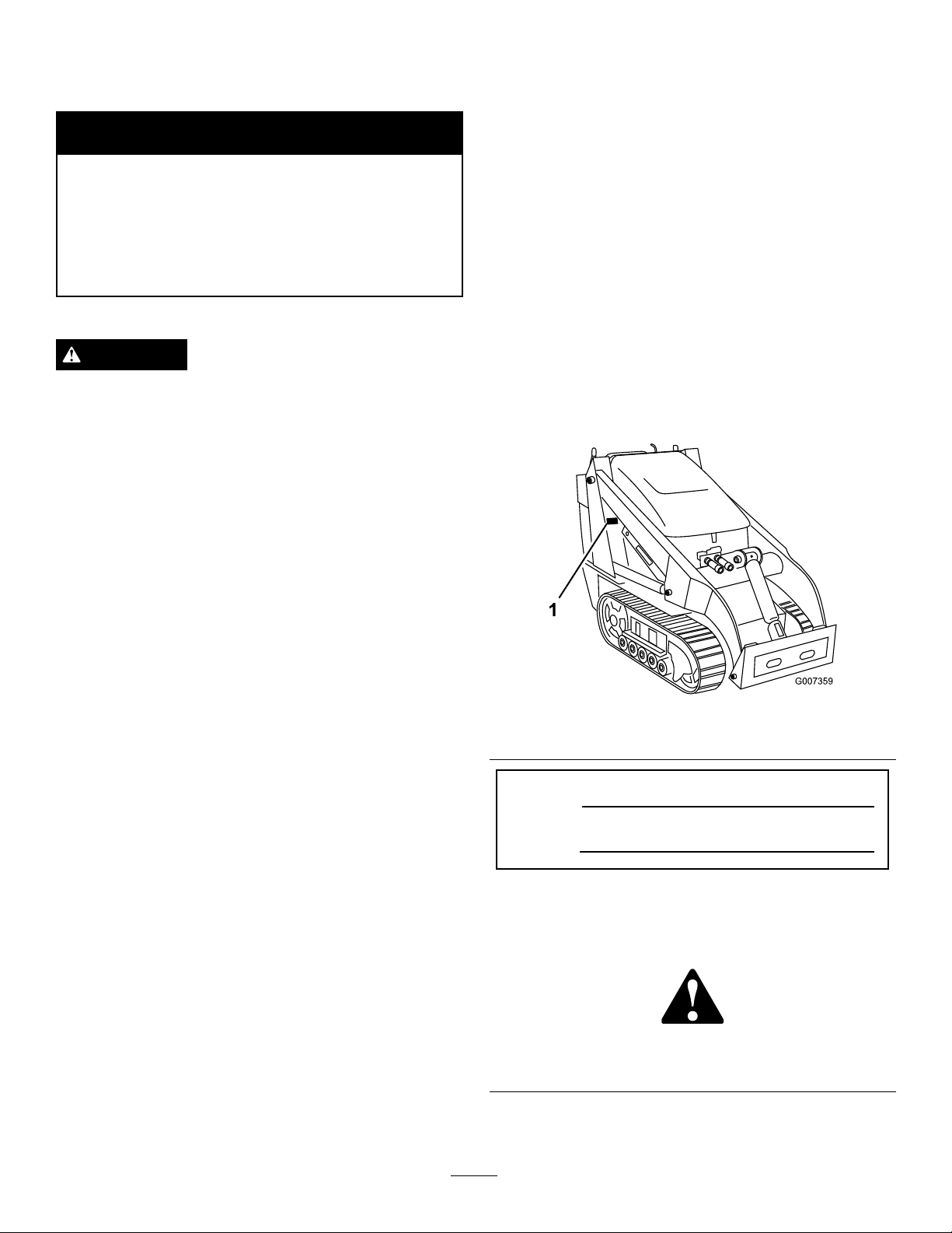
yourproductready .Figure1identiesthelocationofthe
modelandserialnumbersontheproduct.Writethenumbers
inthespaceprovided.
Becauseinsomeareastherearelocal,state,orfederal
regulationsrequiringthatasparkarresterbeusedonthe
engineofthismachine,asparkarresterisavailableas
anoption.Ifyourequireasparkarrester,contactyour
AuthorizedToroServiceDealer.
GenuineTorosparkarrestersareapprovedbytheUSDA
ForestryService.
Important:ItisaviolationofCaliforniaPublic
ResourceCodeSection4442touseoroperatetheengine
onanyforest-covered,brush-covered,orgrass-covered
landwithoutasparkarrestermufermaintainedin
workingorder,ortheengineconstricted,equipped,and
maintainedforthepreventionofre.Otherstatesor
federalareasmayhavesimilarlaws.
ThissparkignitionsystemcomplieswithCanadianICES-002.
Theenclosed
informationregardingtheUSEnvironmentalProtection
Agency(EPA)andtheCaliforniaEmissionControl
Regulationofemissionsystems,maintenance,and
warranty.Replacementsmaybeorderedthroughthe
enginemanufacturer.
Engine Owner's Man ual
issuppliedfor
Figure1
1.Modelandserialnumberlocation
ModelNo.
SerialNo.
Thismanualidentiespotentialhazardsandhassafety
messagesidentiedbythesafetyalertsymbol(
whichsignalsahazardthatmaycauseseriousinjuryordeath
ifyoudonotfollowtherecommendedprecautions.
Figure2),
©2012—TheToro®Company
8111LyndaleAvenueSouth
Bloomington,MN55420
Figure2
1.Safetyalertsymbol
Thismanualuses2otherwordstohighlightinformation.
Importantcallsattentiontospecialmechanicalinformation
Contactusatwww.T oro.com.
2
PrintedintheUSA.
AllRightsReserved
Page 3

andNoteemphasizesgeneralinformationworthyofspecial
attention.
Contents
Introduction..................................................................2
Safety...........................................................................4
SafeOperatingPractices...........................................4
SoundPressureLevel...............................................6
SoundPower..........................................................6
VibrationLevel.......................................................6
StabilityData..........................................................7
SlopeIndicator.......................................................8
SafetyandInstructionalDecals.................................9
ProductOverview.........................................................13
Controls...............................................................13
Specications........................................................16
Attachments/Accessories........................................16
Operation....................................................................17
AddingFuel...........................................................17
CheckingtheEngineOilLevel.................................18
CheckingtheHydraulicFluidLevel...........................18
StartingandStoppingtheEngine..............................19
StoppingtheTractionUnit......................................19
MovingaNon-functioningTractionUnit...................19
UsingtheCylinderLock..........................................20
UsingAttachments.................................................20
SecuringtheTractionUnitforTransport....................22
LiftingtheTractionUnit..........................................22
Maintenance.................................................................23
RecommendedMaintenanceSchedule(s)......................23
PremaintenanceProcedures........................................24
OpeningtheHood.................................................24
ClosingtheHood...................................................24
OpeningtheRearAccessCover................................24
ClosingtheRearAccessCover.................................25
RemovingtheSideScreens......................................25
InstallingtheSideScreens........................................25
RemovingtheFrontScreen......................................25
Lubrication...............................................................26
GreasingtheTractionUnit......................................26
EngineMaintenance..................................................27
ServicingtheAirCleaner.........................................27
ServicingtheCarbonCanister..................................27
ServicingtheEngineOil..........................................28
ServicingtheSparkPlugs.........................................29
FuelSystemMaintenance...........................................30
ChangingtheFuelFilter..........................................30
DrainingtheFuelTank...........................................31
ElectricalSystemMaintenance....................................31
ServicingtheBattery...............................................31
DriveSystemMaintenance.........................................33
ServicingtheTracks................................................33
BeltMaintenance......................................................36
Inspecting/ReplacingtheDriveBelt.........................36
ControlsSystemMaintenance.....................................37
AdjustingtheTractionControlAlignment.................37
AdjustingtheTractionControlNeutral
Position.............................................................38
AdjustingtheTrackingoftheTractionControl,
FullForwardPosition..........................................38
HydraulicSystemMaintenance....................................39
ReplacingtheHydraulicFilter..................................39
ChangingtheHydraulicFluid...................................40
CheckingtheHydraulicLines...................................41
Cleaning...................................................................42
RemovingDebrisfromtheTractionUnit...................42
CleaningtheChassis...............................................42
Storage........................................................................44
Troubleshooting...........................................................45
Schematics...................................................................46
3
Page 4

Safety
Improperuseormaintenancebytheoperatororowner
canresultininjury.Toreducethepotentialforinjury,
complywiththesesafetyinstructionsandalways
payattentiontothesafetyalertsymbol,which
means:
instruction.Failuretocomplywiththeinstructionmay
resultinpersonalinjuryordeath.
SafeOperatingPractices
Thisproductiscapableofamputatinghandsandfeet.Always
followallsafetyinstructionstoavoidseriousinjuryordeath.
Engineexhaustcontainscarbonmonoxide,an
odorless,deadlypoisonthatcankillyou.
Donotruntheengineindoorsorinanenclosed
area.
Training
•ReadtheOperator'sManualandothertrainingmaterial.If
•Becomefamiliarwiththesafeoperationoftheequipment,
•Alloperatorsandmechanicsshouldbetrained.The
•Neverletchildrenoruntrainedpeopleoperateorservice
•Theowner/usercanpreventandisresponsiblefor
Preparation
•Evaluatetheterraintodeterminewhataccessoriesand
•Wearappropriateclothingincludinghardhat,safety
•Inspecttheareawheretheequipmentistobeusedand
•Useextracarewhenhandlinggasolineandotherfuels.
Caution
,
W ar ning
,or
Danger
—personalsafety
WARNING
theoperator(s)ormechanic(s)cannotreadEnglish,itis
theowner'sresponsibilitytoexplainthismaterialtothem.
operatorcontrols,andsafetysigns.
ownerisresponsiblefortrainingtheusers.
theequipment.Localregulationsmayrestricttheageof
theoperator.
accidentsorinjuriesoccurringtohimselforherself,other
peopleorproperty.
attachmentsareneededtoproperlyandsafelyperform
thejob.Onlyuseaccessoriesandattachmentsapproved
bythemanufacturer.
glasses,longpants,safetyshoes,andhearingprotection.
Longhair,looseclothingorjewelrymaygettangledin
movingparts.
removeallobjectssuchasrocks,toys,andwirewhichcan
bethrownbythemachine.
Theyareammableandvaporsareexplosive.
–Useonlyanapprovedcontainer
–Neverremovethegascaporaddfuelwiththeengine
running.Allowtheenginetocoolbeforerefueling.
Donotsmoke.
–Neverrefuelordrainthemachineindoors.
•Checkthattheoperator'spresencecontrols,safety
switches,andshieldsareattachedandfunctioning
properly.Donotoperateunlesstheyarefunctioning
properly.
Operation
•Neverrunanengineinanenclosedarea.
•Onlyoperateingoodlight,keepingawayfromholesand
hiddenhazards.
•Besurealldrivesareinneutralandparkingbrakeis
engagedbeforestartingtheengine.Onlystarttheengine
fromtheoperator'sposition.
•Slowdownanduseextracareonhillsides.Besureto
travelintherecommendeddirectiononhillsides.Turf
conditionscanaffectthemachine'sstability.
•Slowdownandusecautionwhenmakingturnsandwhen
changingdirectionsonslopes.
•Neveroperatewiththeguardsnotsecurelyinplace.Be
sureallinterlocksareattached,adjustedproperly,and
functioningproperty.
•Donotchangetheenginegovernorsettingoroverspeed
theengine.
•Stoponlevelground,lowerimplements,disengagethe
auxiliaryhydraulics,engageparkingbrake,shutoffthe
enginebeforeleavingtheoperator'spositionforany
reason.
•Keephandsandfeetawayfrommovingattachments.
•Lookbehindanddownbeforebackinguptobesureof
aclearpath.
•Nevercarrypassengersandkeeppetsandbystanders
away.
•Slowdownandusecautionwhenmakingturnsand
crossingroadsandsidewalks.
•Donotoperatethemachineundertheinuenceof
alcoholordrugs.
•Usecarewhenloadingorunloadingthemachineintoa
trailerortruck.
•Usecarewhenapproachingblindcorners,shrubs,trees,
orotherobjectsthatmayobscurevision.
•Readallattachmentmanuals.
•Ensurethattheareaisclearofotherpeoplebefore
operatingthetractionunit.Stopthetractionunitif
anyoneentersthearea.
•Neverleavearunningtractionunitunattended.Always
lowertheloaderarms,stoptheengine,settheparking
brake,andremovethekeybeforeleaving.
•Donotexceedtheratedoperatingcapacity,asthetraction
unitmaybecomeunstablewhichmayresultinlossof
control.
•Donotcarryaloadwiththearmsraised.Alwayscarry
loadsclosetotheground.
4
Page 5

•Donotover-loadtheattachmentandalwayskeepthe
loadlevelwhenraisingtheloaderarms.Logs,boards,and
otheritemscouldrolldowntheloaderarms,injuringyou.
•Neverjerkthecontrols;useasteadymotion.
•Watchfortrafcwhenoperatingnearorcrossing
roadways.
•Donottouchpartswhichmaybehotfromoperation.
Allowthemtocoolbeforeattemptingtomaintain,adjust,
orservice.
•Checkforoverheadclearances(i.e.branches,doorways,
electricalwires)beforedrivingunderanyobjectsanddo
notcontactthem.
•Ensurethatyouoperatethetractionunitinareaswhere
therearenoobstaclesincloseproximitytotheoperator.
Failuretomaintainadequatedistancefromtrees,walls,
andotherbarriersmayresultininjuryasthetractionunit
backsupduringoperationiftheoperatorisnotattentive
tothesurroundings.Onlyoperatetheunitinareaswhere
thereissufcientclearancefortheoperatortosafely
maneuvertheproduct.
•Beforedigging,havetheareamarkedforunderground
utilities,anddonotdiginmarkedareas.
•Locatethepinchpointareasmarkedonthetractionunit
andattachmentsandkeephandsandfeetawayfrom
theseareas.
•Beforeoperatingthetractionunitwithanattachment,
ensurethattheattachmentisproperlyinstalled.
•Lightningcancausesevereinjuryordeath.Iflightning
isseenorthunderisheardinthearea,donotoperate
themachine;seekshelter.
SlopeOperation
Slopesareamajorfactorrelatedtoloss-of-controland
tip-overaccidents,whichcanresultinsevereinjuryordeath.
Allslopesrequireextracaution.
•Donotoperatethetractionunitonhillsidesorslopes
exceedingtheanglesrecommendedintheStabilityData
sectionandthoseintheattachmentOperator'sManual.See
alsothe
•Operateupanddownslopeswiththeheavyendof
thetractionunituphill.Weightdistributionchanges.
Anemptybucketwillmaketherearofthetractionunit
theheavyend,andafullbucketwillmakethefrontofthe
tractionunittheheavyend.Mostotherattachmentswill
makethefrontoftractionunittheheavyend.
•Raisingtheloaderarmsonaslopewillaffectthestability
ofthemachine.Wheneverpossible,keeptheloaderarms
intheloweredpositionwhenonslopes.
•Removinganattachmentonaslopewillmaketherearof
thetractionunitheavy.Referto
determinewhethertheattachmentcanbesafelyremoved
ontheslope.
•Removeobstaclessuchasrocks,treelimbs,etc.fromthe
workarea.Watchforholes,ruts,orbumps,asuneven
SlopeIndicator(page8).
StabilityData(page7)to
terraincouldoverturnthetractionunit.Tallgrasscan
hideobstacles.
•UseonlyToro-approvedattachments.Attachmentscan
changethestabilityandtheoperatingcharacteristicsof
thetractionunit.Warrantymaybevoidedifusedwith
unapprovedattachments.
•Keepallmovementsonslopesslowandgradual.Donot
makesuddenchangesinspeedordirection.
•Avoidstartingorstoppingonaslope.Ifthetractionunit
losestraction,proceedslowly,straightdowntheslope.
•Avoidturningonslopes.Ifyoumustturn,turnslowly
andkeeptheheavyendofthetractionunituphill.
•Donotoperateneardrop-offs,ditches,orembankments.
Thetractionunitcouldsuddenlyturnoverifatrackgoes
overtheedgeofaclifforditch,orifanedgecavesin.
•Donotoperateonwetgrass.Reducedtractioncould
causesliding.
•Donotparkthetractionunitonahillsideorslope
withoutloweringtheattachmenttotheground,setting
theparkingbrake,andchockingthetracks.
MaintenanceandStorage
•Disengagetheauxiliaryhydraulics,lowertheattachment,
settheparkingbrake,stoptheengine,andremovethe
key.Waitforallmovementtostopbeforeadjusting,
cleaning,orrepairing.
•Cleandebrisfromattachments,drives,mufers,and
enginetohelppreventres.Cleanupoilorfuelspillage.
•Lettheenginecoolbeforestoringanddonotstorenear
ame.
•Donotstorefuelnearamesordrainindoors.
•Parkthemachineonlevelground.Neverallowuntrained
personneltoservicethemachine.
•Usejackstandstosupportcomponentswhenrequired.
•Carefullyreleasepressurefromcomponentswithstored
energy.
•Disconnectthebatteryorremovethesparkplugwires
beforemakinganyrepairs.Disconnectthenegative
terminalrstandthepositivelast.Reconnectpositive
rstandnegativelast.
•Keephandsandfeetawayfrommovingparts.Ifpossible,
donotmakeadjustmentswiththeenginerunning.
•Chargebatteriesinanopenwellventilatedarea,away
fromsparkandames.Unplugthechargerbefore
connectingordisconnectingitfromthebattery.Wear
protectiveclothinganduseinsulatedtools.
•Keepallpartsingoodworkingconditionandallhardware
tightened.Replaceallwornordamageddecals.
•Ifanymaintenanceorrepairrequirestheloaderarmsto
beintheraisedposition,securethearmsintheraised
positionwiththehydrauliccylinderlock.
5
Page 6

•Securetheloaderarmvalvewiththeloadervalvelock
anytimeyouneedtostopthemachinewiththeloader
armsraised.
Thesoundpowerlevelwasdeterminedaccordingtothe
proceduresoutlinedinISO6395.
•Keepnutsandboltstight.Keepequipmentingood
condition.
•Nevertamperwithsafetydevices.
•Keepthetractionunitfreeofgrass,leaves,orotherdebris
build-up.Cleanupoilorfuelspillage.Allowthetraction
unittocoolbeforestoring.
•Useextracarewhenhandlinggasolineandotherfuels.
Theyareammableandvaporsareexplosive.
–Useonlyanapprovedcontainer.
–Neverremovethegascaporaddfuelwhenthe
engineisrunning.Allowtheenginetocoolbefore
refueling.Donotsmoke.
–Neverrefuelthetractionunitindoors.
–Neverstorethetractionunitorfuelcontainerinside
wherethereisanopename,suchasnearawater
heaterorfurnace.
–Neverllacontainerwhileitisinsideavehicle,trunk,
pick-upbed,oranysurfaceotherthantheground.
–Keepcontainernozzleincontactwiththetankduring
lling.
VibrationLevel
Measuredvibrationlevelforrighthand=1.1m/s
Measuredvibrationlevelforlefthand=1.1m/s
UncertaintyValue(K)=0.6m/s
Measuredvaluesweredeterminedaccordingtotheprocedures
outlinedinENISO20643.
2
2
2
•Stopandinspecttheequipmentifyoustrikeanobject.
Makeanynecessaryrepairsbeforerestarting.
•UseonlygenuineTororeplacementpartstoensurethat
originalstandardsaremaintained.
•Batteryacidispoisonousandcancauseburns.Avoid
contactwithskin,eyes,andclothing.Protectyourface,
eyes,andclothingwhenworkingwithabattery.
•Batterygasescanexplode.Keepcigarettes,sparksand
amesawayfromthebattery.
•Keepyourbodyandhandsawayfrompinholeleaks
ornozzlesthatejecthighpressurehydraulicuid.Use
cardboardorpapertondhydraulicleaks;neveruse
yourhands.Hydraulicuidescapingunderpressurecan
penetrateskinandcauseinjuryrequiringsurgerywithina
fewhoursbyaqualiedsurgeonorgangrenemayresult.
SoundPressureLevel
SoundPressureLevelThisunithasasoundpressurelevelat
theoperator’searof90dBA,whichincludesanUncertainty
Value(K)of1dBA.
Soundpressurelevelwasdeterminedaccordingtothe
proceduresoutlinedinEN11201.
SoundPower
Thisunithasaguaranteedsoundpowerlevelof103dBA,
whichincludesanUncertaintyValue(K)of1dBA.
6
Page 7
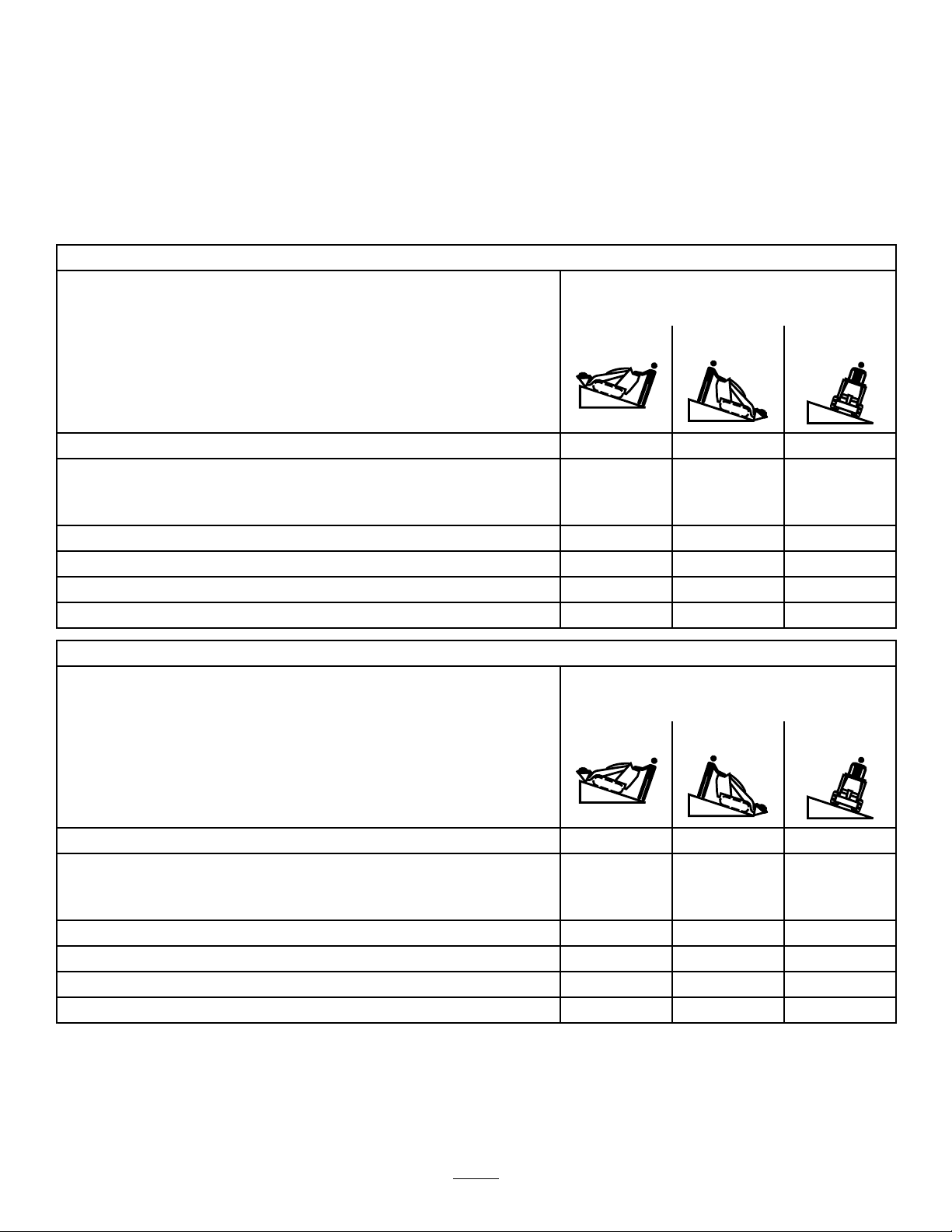
StabilityData
Thefollowingtableslistthemaximumsloperecommendedforthetractionunitinthepositionslistedinthetables.Slopesover
thelisteddegreemaycausethetractionunittobecomeunstable.Thedatainthetablesassumethattheloaderarmsarefully
lowered;raisedarmsmayaffectthestability .
Ineachattachmentmanualisasetofthreestabilityratings,oneforeachhillposition.Todeterminethemaximumslopeyou
cantraversewiththeattachmentinstalled,ndthedegreeofslopethatcorrespondstothestabilityratingsoftheattachment.
Example:IftheattachmentinstalledonaTX427tractionunithasaFrontUphillratingofB,aRearUphillratingofD ,anda
SideUphillratingofC,thenyoucoulddriveforwardupa20°slope,rearwardupa12°slope,orsidewaysona14°slope,as
listedinthefollowingtablefortheTX427tractionunit.
Model22321and22321G
MaximumRecommendedSlopewhen
Operatingwith:
FrontUphillRearUphill
Conguration
Tractionunitwithoutattachment
Tractionunitwithanattachmentratedwithoneofthefollowingstabilityratings
foreachslopeposition:*
A
B
C17°17°14°
D
E
Model22322
11°21°19°
25°25°20°
20°20°18°
10°12°9°
5°5°5°
MaximumRecommendedSlopewhen
Operatingwith:
FrontUphillRearUphill
SideUphill
SideUphill
Conguration
Tractionunitwithoutattachment
Tractionunitwithanattachmentratedwithoneofthefollowingstabilityratings
foreachslopeposition:*
A
B
C18°16°16°
D
E
12°20°23°
25°25°25°
22°22°22°
10°10°10°
5°5°5°
7
Page 8
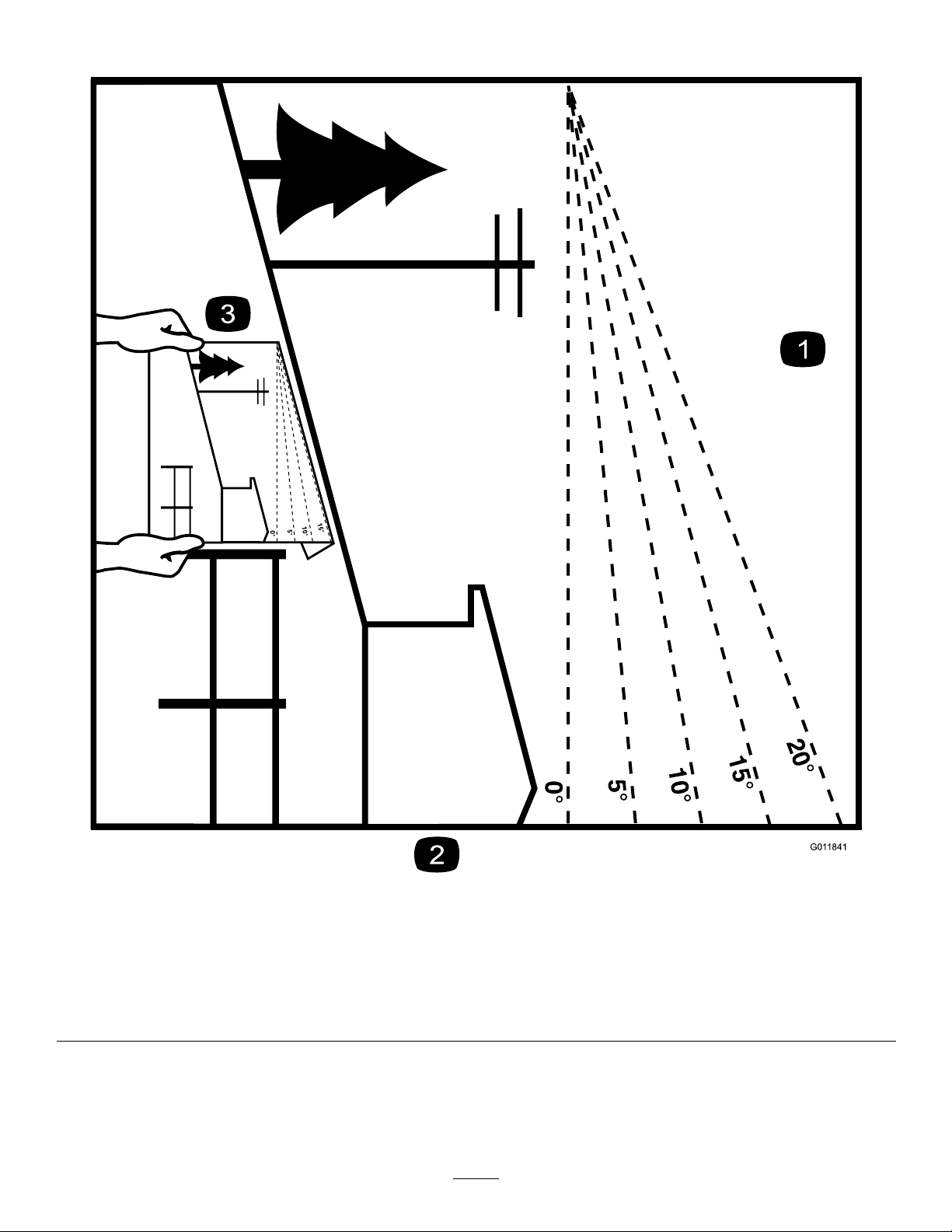
SlopeIndicator
G011841
Figure3
Thispagemaybecopiedforpersonaluse.
1.Todeterminethemaximumslopeyoucansafelyoperatethemachineon,refertotheStabilityDatasection.Usetheslope
indicatortodeterminethedegreeofslopeofhillsbeforeoperating.Donotoperatethismachineonaslopegreaterthanthat
speciedintheStabilityDatasection.Foldalongtheappropriatelinetomatchtherecommendedslope.
2.Alignthisedgewithaverticalsurface,atree,building,fencepole,etc.
3.Exampleofhowtocompareslopewithfoldededge.
8
Page 9
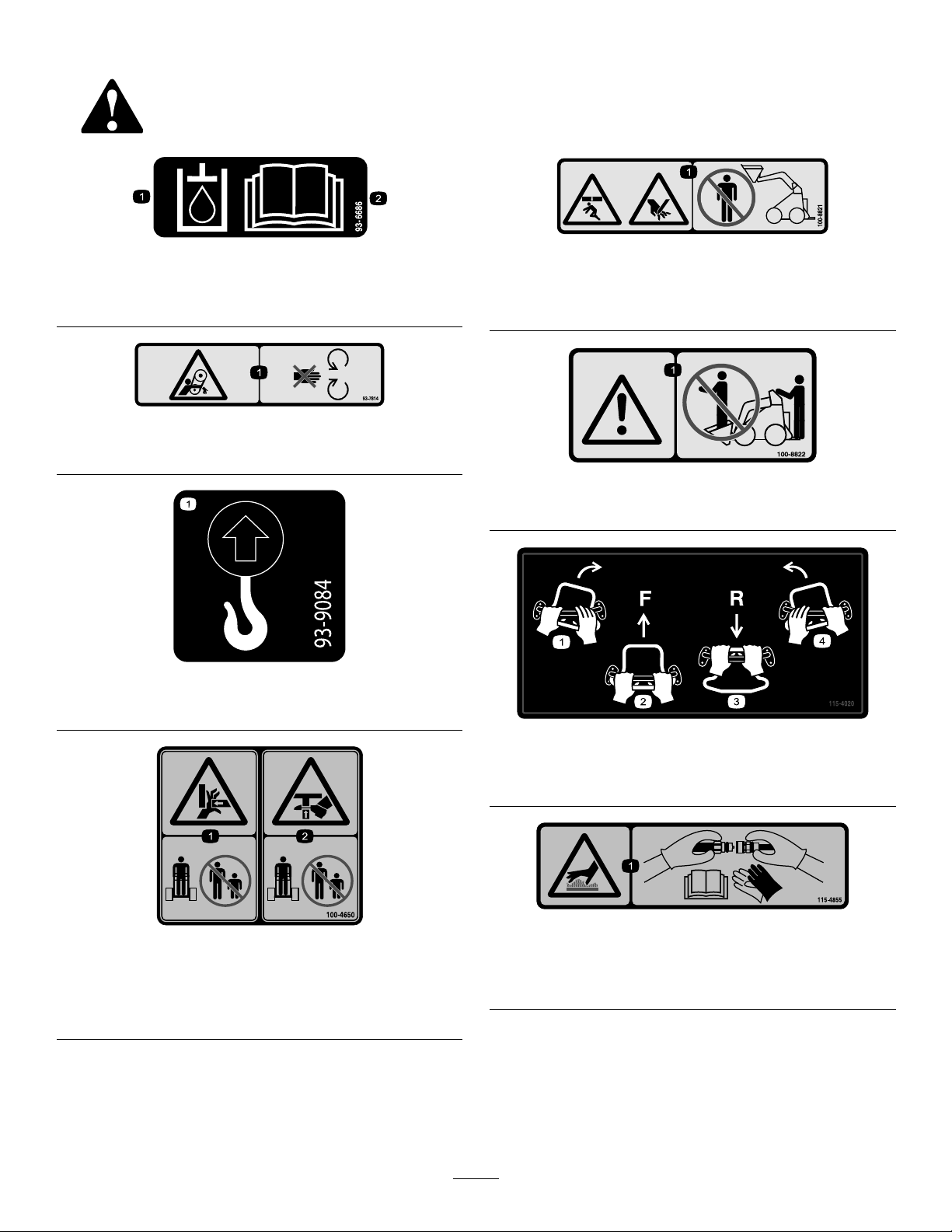
SafetyandInstructionalDecals
Safetydecalsandinstructionsareeasilyvisibletotheoperatorandarelocatednearanyareaofpotential
danger.Replaceanydecalthatisdamagedorlost.
93-6686
1.Hydraulicoil
2.ReadtheOperator'sManual.
93-7814
1.Entanglementhazard,belt—stayawayfrommovingparts.
93-9084
100-8821
1.Crushinghazardandcuttinghazardofhand—stayasafe
distancefromthefrontofthetractionunitwhentheloader
armsareraised.
100-8822
1.Warning—donotcarrypassengers.
1.Liftpoint
2.Tie-downpoint
100-4650
1.Crushinghazardofhand—keepbystandersasafedistance
fromthemachine.
2.Crushinghazardoffoot—keepbystandersasafedistance
fromthemachine.
115-4020
1.Turnright3.Reverse
2.Forward
4.Turnleft
115-4855
1.Hotsurface/burnhazard—wearprotectivegloveswhen
handlingthehydrauliccouplersandreadtheOperator's
Manualforinformationonhandlinghydrauliccomponents.
9
Page 10
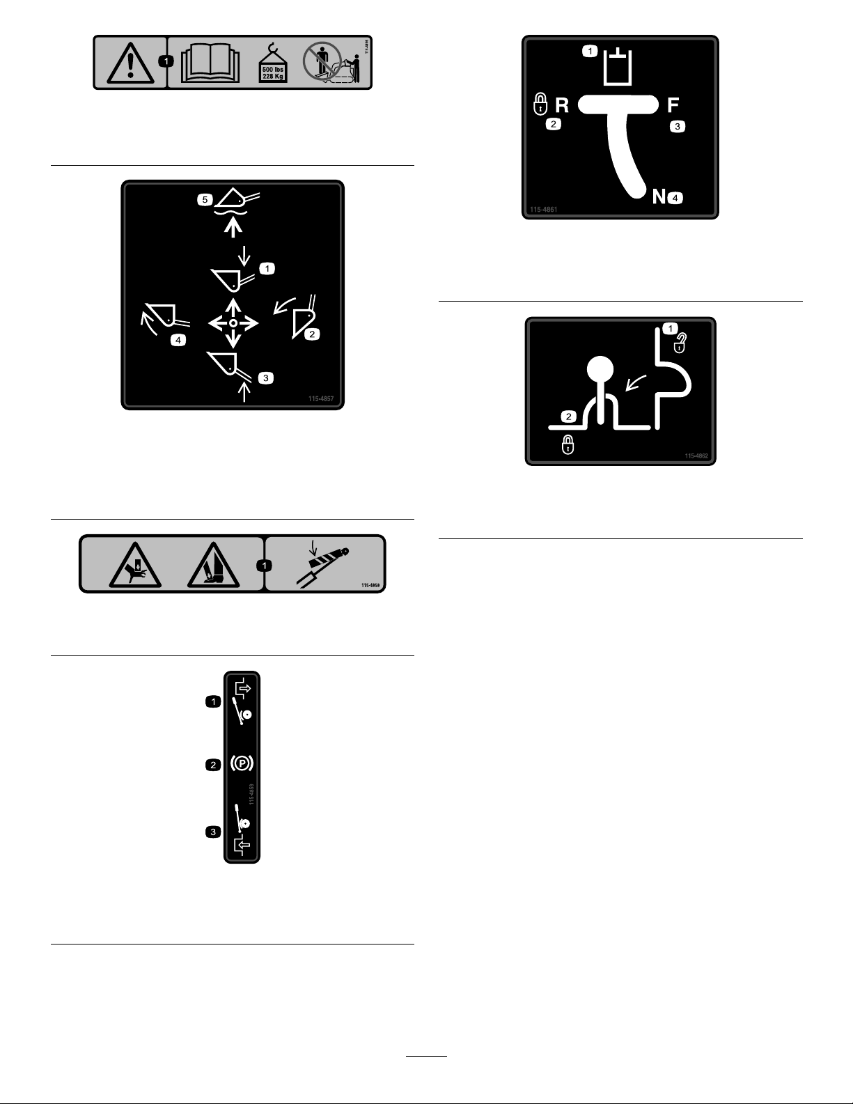
115-4856
1.Warning—readtheOperator'sManual;maximumload
ratingof500lb(228Kg);noriders.
115-4857
115-4861
1.Auxiliaryhydraulics3.Forward
2.Lockedreverse(detent)4.Neutral(off)
1.Lowertheloaderarms.
2.Dumpthebucket.5.Floatthebucketonthe
3.Raisetheloaderarms.
4.Curlthebucket.
ground.
115-4858
1.Crushinghazardofhandsorfeet—installthecylinderlock.
1.Loadervalvelock,
unlocked
115-4862
2.Loadervalvelock,locked
1.Disengaged3.Engaged
2.Parkingbrake
115-4859
10
Page 11
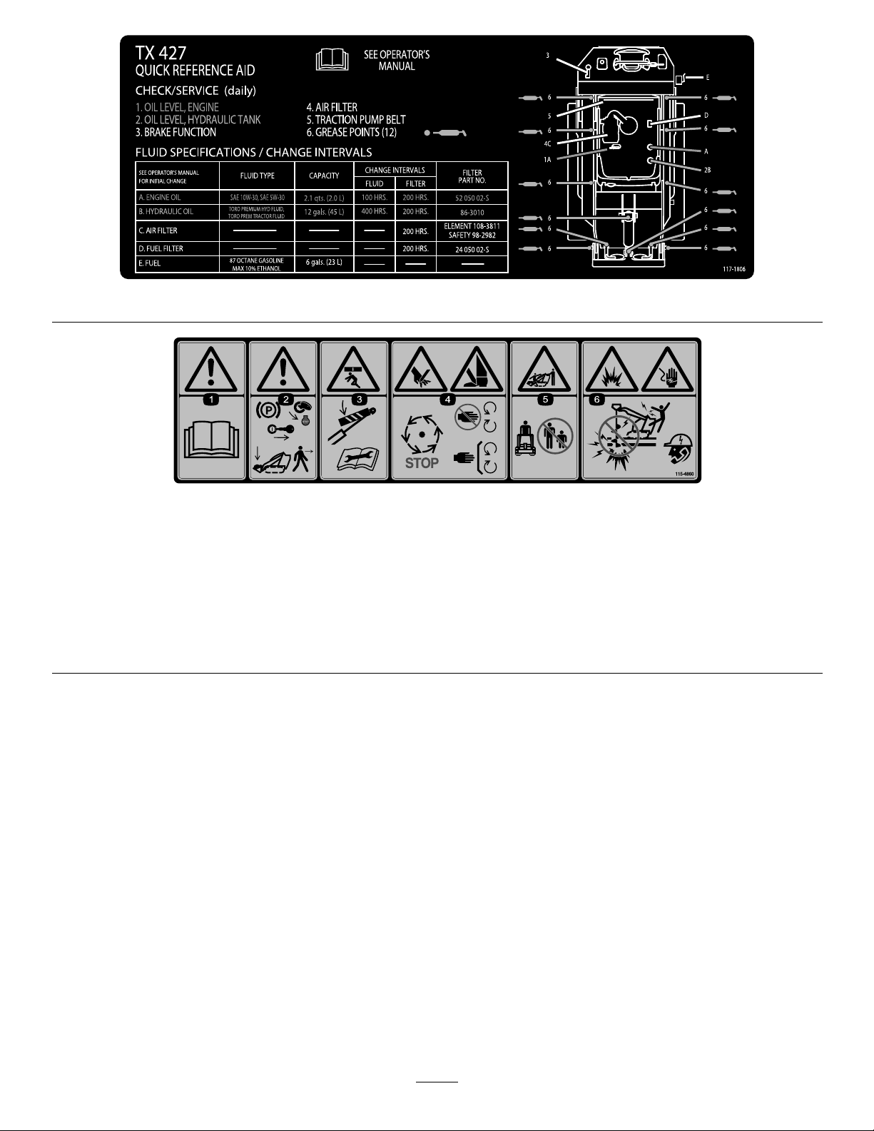
117–1806
115-4860
1.Warning—readtheOperator'sManual.
2.Warning—settheparkingbrake,stoptheengine,removetheignitionkeyandlowertheloaderarmsbeforeleavingthemachine.
3.Crushinghazard—installthecylinderlockandreadtheinstructionsbeforeservicingorperformingmaintenance.
4.Cuttinghazardofhandsorfeet—waitforallmovingpartstostop;stayawayfrommovingparts;keepallguardsandshieldsin
place.
5.Crushing/dismembermenthazardofbystanders—keepbystandersasafedistancefromthemachine.
6.Explosionandelectricshockhazard—donotdiginareaswithburiedgasorelectricallines;contactlocalpowerorganizations
beforedigging.
11
Page 12

117-4045
1.ReadtheOperator'sManual,located
insidetherearaccesscover.
2.Fast
3.Continuousvariablesetting
4.Slow
5.Throttle11.Hourmeter17.Tippinghazard—movethetractionunit
6.On
7.Choke
8.Off
9.Fuel15.Warning—donotoperatethismachine
10.Hydraulicoiltemperature16.Electricshockhazard,overheadpower
12.Engine—start18.Tippinghazard—slowthetractionunit
13.Engine—run
14.Engine—stop
unlessyouaretrained.
lines—stayawayfromoverheadpower
lines.
withtheheavyenduphill;donottravel
withtheloaderarmsraised.
whenturning,donottravelfastwhen
turning,lookbehindanddownwhen
reversing.
12
Page 13
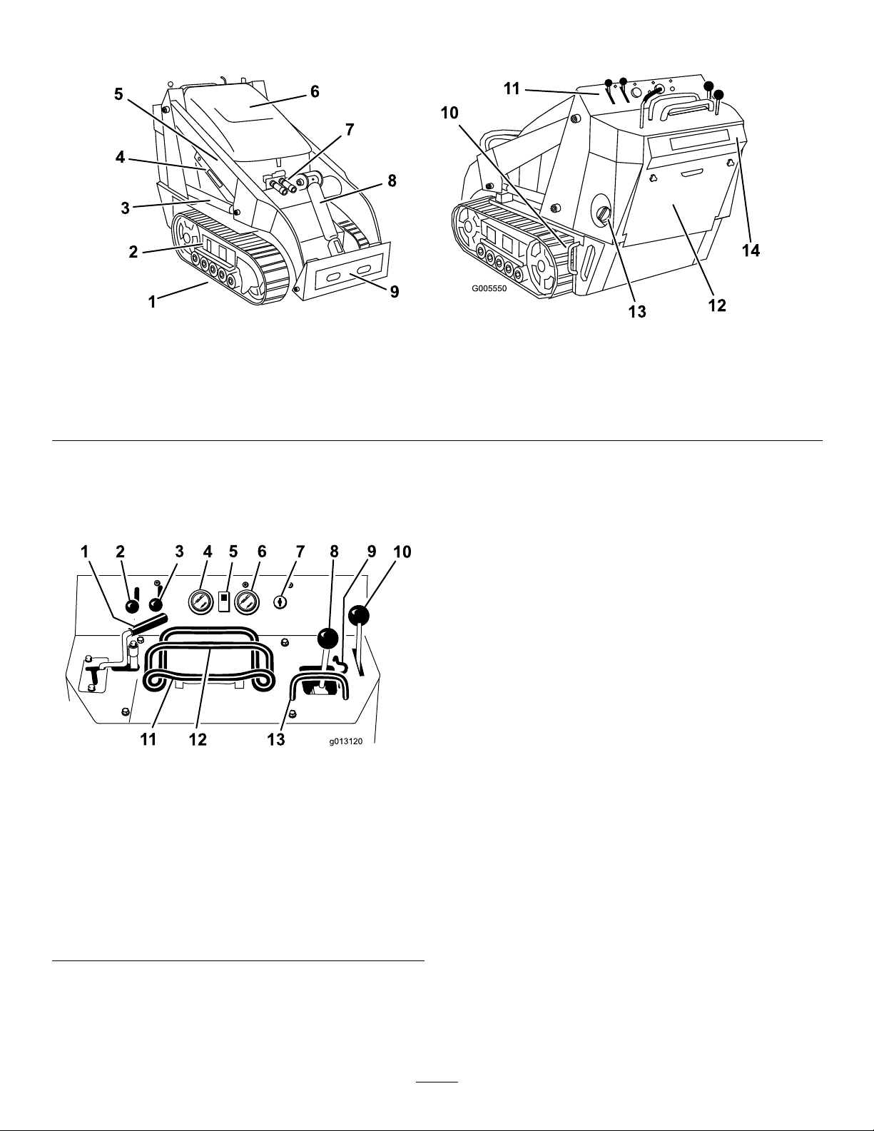
ProductOverview
Figure4
1.Track5.Loaderarms9.Mountplate13.Fueltank
2.Trackadjustmentchamber6.Hood
3.Liftcylinder
4.Cylinderlock
7.Auxiliaryhydrauliccouplers
8.Tiltcylinder12.Rearaccesscover
10.Tie-down/liftloop14.Reversesafetyplate
11.Controlpanel
Controls
Becomefamiliarwithallthecontrols(Figure5)beforeyou
starttheengineandoperatethetractionunit.
Figure5
1.Auxiliaryhydraulicslever
2.Throttlelever9.Loadervalvelock
3.Chokelever
4.Fuelgauge11.Tractioncontrol
5.Hydraulicoiltemperature
light
6.Hourmeter/tachometer13.Loadercontrolreference
7.Keyswitch
8.Loaderarm/attachmenttilt
lever
10.Parkingbrakelever
12.Referencebar
bar
Tostarttheengine,rotatethekeytothestartposition.Release
thekeywhenenginestartsanditwillmoveautomaticallyto
therunposition.
Tostoptheengine,rotatethekeytotheoffposition.
ThrottleLever
Movethecontrolforwardtoincreasetheenginespeedand
rearwardtodecreasespeed.
ChokeLever
Beforestartingacoldengine,movethechokeleverforward.
Aftertheenginestarts,regulatethechoketokeeptheengine
runningsmoothly.Assoonaspossible,movethechokelever
allthewayrearward.
Note:Awarmenginerequireslittleornochoking.
ReferenceBar
Whendrivingthetractionunit,usethereferencebaras
ahandleandaleveragepointforcontrollingthetraction
controlandtheauxiliaryhydraulicslever.Toensuresmooth,
controlledoperation,donottakebothhandsoffofthe
referencebarwhileoperatingthetractionunit.
KeySwitch
Thekeyswitch,usedtostartandstoptheengine,hasthree
positions:off,run,andstart.
13
Page 14
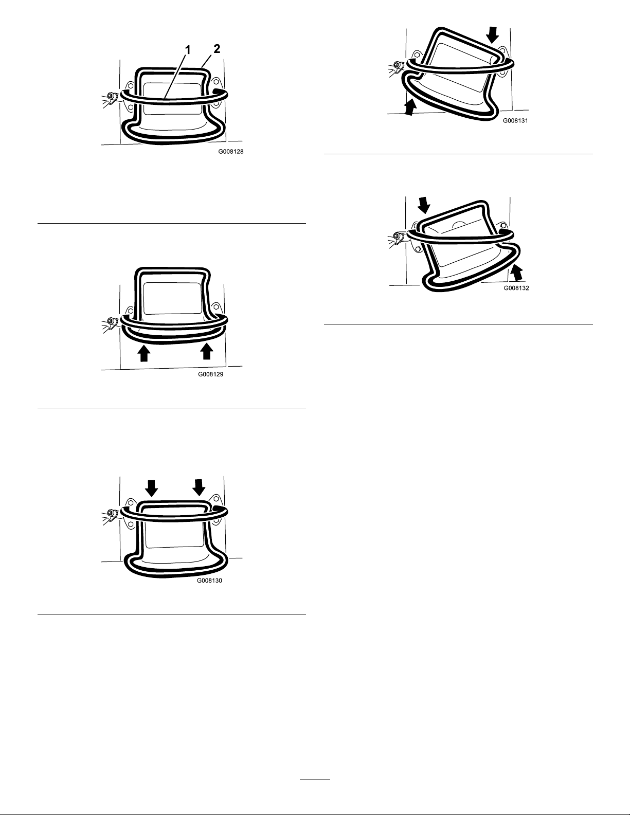
TractionControl
G008131
G008132
Figure9
Figure6
1.Referencebar(doesnotmovetogiveyouareferencepoint
andaxedhandletoholdwhileoperatingthetractionunit)
2.Tractioncontrol(movestocontrolthemachine)
•Tomoveforward,movethetractioncontrolforward
(Figure7).
Figure7
•Tomoverearward,movethetractioncontrolrearward
(Figure8).Whenreversing,lookbehindfor
obstructionsandkeepyourhandsonthereference
bar(Figure7).
•Toturnleft,rotatethetractioncontrolcounterclockwise
(Figure10).
Figure10
•Tostop,releasethetractioncontrol(Figure6).
Note:Thefartheryoumovethetractioncontrolinany
direction,thefasterthemachinewillmoveinthatdirection.
LoaderArm/AttachmentTiltLever
Totilttheattachmentforward,slowlymovethelevertothe
right(Figure11).
Totilttheattachmentrearward,slowlymovethelevertothe
left(Figure11).
Figure8
•Toturnright,rotatethetractioncontrolclockwise
(Figure9).
Tolowertheloaderarms,slowlymovetheleverforward
(Figure11).
Toraisetheloaderarms,slowlymovetheleverrearward
(Figure11).
Youcanalsopushtheleverfullyforwardintoadetent
position(Figure11)toreleasetheloaderarmssothatthe
attachmentrestsontheground.Thisallowsattachmentssuch
asthelevelerandthehydraulicbladetofollowthecontours
oftheground(i.e.,oat)whengrading.
14
Page 15
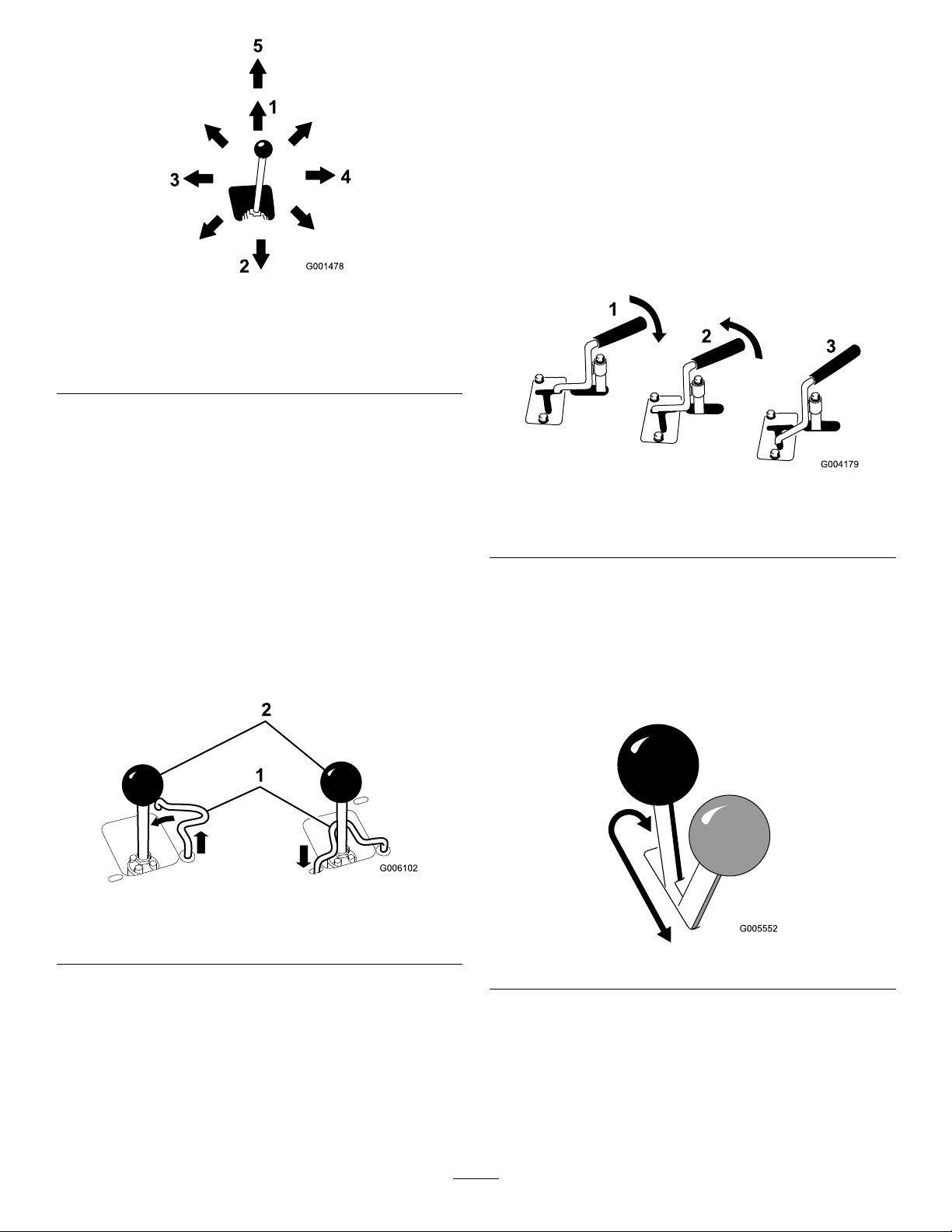
Figure11
AuxiliaryHydraulicsLever
Tooperateahydraulicattachmentintheforwarddirection,
rotatetheauxiliaryhydraulicsleverrearwardandpullitdown
tothereferencebar(Figure13,number1).
Tooperateahydraulicattachmentinreversedirection,rotate
thehydraulicsleverrearward,thenmoveitleftintotheupper
slot(Figure13,number2).
Ifyoureleasetheleverwhileintheforwardposition,thelever
willautomaticallyreturntotheneutralposition(Figure13,
number3).Ifitisinthereverseposition,itwillremainthere
untilyoupullitoutoftheslot.
1.Lowertheloaderarms
2.Raisetheloaderarms
3.Tilttheattachment
rearward
4.Tilttheattachmentforward
5.Detent(Float)position
Bymovingthelevertoanintermediateposition(suchas,
forwardandleft),youcanmovetheloaderarmsandtiltthe
attachmentatthesametime.
LoaderValveLock
Theloadervalvelocksecurestheloaderarm/attachmenttilt
leversothatyoucannotpushitforward.Thishelpstoensure
thatnoonewillaccidentallylowertheloaderarmsduring
maintenance.Securetheloaderarmswiththelockanytime
youneedtostopthemachinewiththeloaderarmsraised.
Tosetthelock,liftuponitsoitclearstheholeinthecontrol
panelandswingittotheleftinfrontoftheloaderarmlever,
pushingitdownintothelockedposition(Figure12).
Figure13
1.Forwardowhydraulics
2.Reverseowhydraulics
3.Neutral
ParkingBrakeLever
Tosettheparkingbrake,pushthebrakeleverforwardandto
theleftandthenpullitrearward(Figure14).
Note:Thetractionunitmayrollslightlybeforethebrakes
engageinthedrivesprocket.
Figure12
1.Loadervalvelock
2.Loaderarm/attachmenttilt
lever
LoaderControlReferenceBar
Theloadercontrolreferencebarhelpsstabilizeyourhand
whileoperatingtheloaderarm/attachmenttiltlever.
Figure14
Toreleasethebrake,pushtheleverforwardandthenright,
intothenotch.
FuelGauge
Thisgaugemeasurestheamountoffuelinthefueltank.
15
Page 16

HydraulicOilTemperatureLight
After50hoursandthenevery100hoursthereafter(that
isat150,250,350,etc.)thescreendisplaysCHGOILto
Ifthehydraulicoilgetstoohot,thislightilluminatesandan
audiblealarmsounds.Ifthishappens,stoptheengineand
allowthetractionunittocool.
remindyoutochangetheengineoil.Afterevery100hours,
thescreendisplaysSVCtoremindyoutoperformtheother
maintenanceproceduresbasedona100,200,or400hour
schedule.Thesereminderscomeonstartingthreehoursprior
HourMeter/Tachometer
totheserviceintervaltimeandashatregularintervalsfor
sixhours.
Whentheengineisoff,thehourmeter/tachometerdisplays
thenumberofhoursofoperationthathavebeenloggedon
thetractionunit.Whentheengineisrunning,itdisplaysthe
speedoftheengineinrevolutionsperminute(rpm).
Specications
Note:Specicationsanddesignaresubjecttochangewithoutnotice.
Model22321and22321G
Width
Length
Height
Weight
Operatingcapacity500lb(227Kg)
Tippingcapacity
Wheelbase
Dumpheight(withnarrowbucket)47inches(1 19cm)
Reach—fullyraised(withnarrowbucket)22inches(55cm)
Heighttohingepin(narrowbucketinhighestposition)66inches(168cm)
34inches(86cm)
71inches(180cm)
46inches(1 17cm)
1880lb(853Kg)
1480lb(671Kg)
31.2inches(79cm)
Model22322
Width
Length
Height
Weight
Operatingcapacity500lb(227Kg)
Tippingcapacity
Wheelbase
Dumpheight(withnarrowbucket)47inches(1 19cm)
Reach—fullyraised(withnarrowbucket)22inches(55cm)
Heighttohingepin(narrowbucketinhighestposition)66inches(168cm)
41inches(104cm)
71inches(180cm)
46inches(1 17cm)
2075lb(941Kg)
1427lb(647Kg)
31.2inches(79cm)
Attachments/Accessories
AselectionofToroapprovedattachmentsandaccessoriesareavailableforusewiththemachinetoenhanceandexpand
itscapabilities.ContactyourAuthorizedServiceDealerorDistributororgotowww .Toro.comforalistofallapproved
attachmentsandaccessories.
Important:UseonlyT oroapprovedattachments.Otherattachmentsmaycreateanunsafeoperatingenvironment
ordamagethetractionunit.
16
Page 17

Operation
Note:Determinetheleftandrightsidesofthemachine
fromthenormaloperatingposition.
Important:Beforeoperating,checkthefuelandoil
level,andremovedebrisfromthetractionunit.Also,
ensurethattheareaisclearofpeopleanddebris.You
shouldalsoknowandhavemarkedthelocationsofall
utilitylines.
AddingFuel
•Forbestresults,useonlyclean,fresh,unleadedgasoline
withanoctaneratingof87orhigher((R+M)/2rating
method).
•Oxygenatedfuelwithupto10%ethanolor15%MTBE
byvolumeisacceptable.
•DoNotuseethanolblendsofgasoline(suchasE15
orE85)withmorethan10%ethanolbyvolume.
Performanceproblemsand/orenginedamagemayresult
whichmaynotbecoveredunderwarranty.
•DoNotusegasolinecontainingmethanol.
•DoNotstorefueleitherinthefueltankorfuelcontainers
overthewinterunlessafuelstabilizerisused.
•DoNotaddoiltogasoline.
DANGER
Incertainconditionsduringfueling,static
electricitycanbereleasedcausingasparkwhich
canignitethegasolinevapors.Areorexplosion
fromgasolinecanburnyouandothersandcan
damageproperty.
•Alwaysplacegasolinecontainersontheground
awayfromyourvehiclebeforelling.
•Donotllgasolinecontainersinsideavehicleor
onatruckortrailerbedbecauseinteriorcarpets
orplastictruckbedlinersmayinsulatethe
containerandslowthelossofanystaticcharge.
•Whenpractical,removegas-poweredequipment
fromthetruckortrailerandrefueltheequipment
withitswheelsontheground.
•Ifthisisnotpossible,thenrefuelsuch
equipmentonatruckortrailerfromaportable
container,ratherthanfromagasolinedispenser
nozzle.
•Ifagasolinedispensernozzlemustbeused,
keepthenozzleincontactwiththerimofthe
fueltankorcontaineropeningatalltimesuntil
fuelingiscomplete.
DANGER
Incertainconditions,gasolineisextremely
ammableandhighlyexplosive.Areorexplosion
fromgasolinecanburnyouandothersandcan
damageproperty.
•Fillthefueltankoutdoors,inanopenarea,
whentheengineiscold.Wipeupanygasoline
thatspills.
•Neverllthefueltankinsideanenclosedtrailer.
•Donotllthefueltankcompletelyfull.Add
gasolinetothefueltankuntilthelevelis1/4to
1/2inch(6to13mm)belowthebottomofthe
llerneck.Thisemptyspaceinthetankallows
gasolinetoexpand.
•Neversmokewhenhandlinggasoline,andstay
awayfromanopenameorwheregasoline
fumesmaybeignitedbyaspark.
•Storegasolineinanapprovedcontainerand
keepitoutofthereachofchildren.Neverbuy
morethana30-daysupplyofgasoline.
•Donotoperatewithoutentireexhaustsystemin
placeandinproperworkingcondition.
UsingStabilizer/Conditioner
Useafuelstabilizer/conditionerinthetractionunitto
providethefollowingbenets:
•Keepsgasolinefreshduringstorageof90daysorless.
Forlongerstorageitisrecommendedthatthefueltank
bedrained.
•Cleanstheenginewhileitruns
•Eliminatesgum-likevarnishbuildupinthefuelsystem,
whichcauseshardstarting
Important:Donotusefueladditivescontaining
methanolorethanol.
Addthecorrectamountofgasstabilizer/conditionertothe
gas.
Note:Afuelstabilizer/conditionerismosteffectivewhen
mixedwithfreshgasoline.Tominimizethechanceofvarnish
depositsinthefuelsystem,usefuelstabilizeratalltimes.
FillingtheFuelTank
1.Parkthetractionunitonalevelsurface,lowerthe
loaderarms,andstoptheengine.
2.Removethekeyandallowtheenginetocool.
3.Cleanaroundthefueltankcapandremoveit.
17
Page 18

Note:Thecapistetheredtothefueltank.
4.Addunleadedgasolinetothefueltank,untilthelevelis
justbelowthebottomofthellerneck.
Important:Donotoverllthecrankcasewithoil
becausetheenginemaybedamaged.
10.Replacethellercapanddipstick.
Important:Thisspaceinthetankallowsgasoline
toexpand.Donotllthefueltankcompletelyfull.
5.Installthefueltankcapsecurely,turningituntilitclicks.
6.Wipeupanygasolinethatmayhavespilled.
CheckingtheEngineOilLevel
ServiceInterval:Beforeeachuseordaily
1.Parkthetractionunitonalevelsurface,lowerthe
loaderarms,andstoptheengine.
2.Removethekeyandallowtheenginetocool.
3.Openthehood.
4.Cleanaroundtheoildipstick(
Figure15).
11.Closethehood.
CheckingtheHydraulicFluid Level
ServiceInterval:Every25hours
HydraulicTankCapacity:12USgallons(45.4l)
RefertoChangingtheHydraulicFluid(page40)forhydraulic
uidspecications.
Important:Alwaysusethecorrecthydraulicuid.
Unspecieduidswilldamagethehydraulicsystem.
1.Removetheattachment,ifone
isinstalled;refertoRemovingan
AttachmentRemovinganAttachment(page21).
2.Parkthetractionunitonalevelsurface,lowerthe
loaderarms,andfullyretractthetiltcylinder.
3.Stoptheengine,removethekey,andallowtheengine
tocool.
4.Openthehoodandremovetheleftsidescreen.
Figure15
1.Oildipstick
5.Pulloutthedipstickandwipethemetalendclean
(
Figure15).
6.Slidethedipstickfullyintothedipsticktube(Figure15).
7.Pullthedipstickoutandlookatthemetalend.
8.Iftheoillevelislow ,cleanaroundtheoilllercapand
removethecap(Figure16).
2.Metalend
5.Cleantheareaaroundthellerneckofthehydraulic
Figure17).
tank(
6.Removethecapfromthellerneckandchecktheuid
levelonthedipstick(Figure17).
Theuidlevelshouldbebetweenthemarksonthe
dipstick.
Figure17
1.Fillerneckcap2.Dipstick
Figure16
1.Fillercap2.Valvecover
9.Slowlypouronlyenoughoilintothevalvecoverto
raisetheleveltotheF(full)mark.
7.Ifthelevelislow,addenoughuidtoraiseittothe
properlevel.
8.Installthecaponthellerneck.
9.Replacetheleftsidescreenandclosethehood.
18
Page 19

StartingandStoppingthe
StoppingtheTractionUnit
Engine
StartingtheEngine
1.Ensurethattheauxiliaryhydraulicsleverisinneutral.
2.MovethechokeleverforwardtotheOnpositionifyou
arestartingacoldengine.
3.Movethethrottlelevermidwaybetweenslow(turtle)
andfast(rabbit)positions.
Note:Awarmorhotenginemaynotrequirechoking.
4.Turntheignitionkeytothestartposition.Whenthe
enginesstarts,releasethekey.
Important:Donotengagethestarterformore
than10secondsatatime.Iftheenginefailsto
start,allowa30secondcool-downperiodbetween
attempts.Failuretofollowtheseinstructionscan
burnoutthestartermotor.
5.Aftertheenginestarts,graduallymovethechoke
leverbacktotheOffposition.Iftheenginestallsor
hesitates,pullthechokeoutagainuntiltheengine
warmsup.
6.Movethethrottlelevertodesiredsetting.
Tostopthetractionunit,releasethetractioncontrol,move
thethrottlelevertoslow(turtle),lowerloaderarmstothe
ground,andstoptheengine.Settheparkingbrakeand
removethekey .
CAUTION
Achildoruntrainedbystandercouldattemptto
operatethetractionunitandbeinjured.
Removethekeyfromtheswitchwhenleavingthe
tractionunit,evenifjustforafewseconds.
MovingaNon-functioning TractionUnit
Important:Donottoworpullthetractionunitwithout
rstopeningthetowvalves,orthehydraulicsystemwill
bedamaged.
1.Stoptheengine.
2.Opentherearaccesscover.
3.Usingawrench,turnthetowvalvesonthehydraulic
pumpstwicecounter-clockwise(Figure18).
Important:Iftheengineisrunathighspeeds
whenthehydraulicsystemiscold(i.e.,whenthe
ambientairtemperatureisnearfreezingorlower),
hydraulicsystemdamagecouldoccur.When
startingtheengineincoldconditions,allowthe
enginetoruninthemiddlethrottlepositionfor
2to5minutesbeforemovingthethrottletofast
(rabbit).
Note:Ifoutdoortemperatureisbelowfreezing,store
thetractionunitinagaragetokeepitwarmerandaid
instarting.
StoppingtheEngine
1.Movethethrottlelever3/4ofthewaytotheFast
position.
2.Lowertheloaderarmstotheground.
3.Turntheignitionkeyoff.
Note:Ifyousetthethrottlelowerthanhalfwayto
fast,theenginewillcontinuetorunforonesecond
afterturningthekeytotheOffposition,preventinga
loudafterrebang.
Note:Iftheenginehasbeenworkinghardorishot,
letitrunforaminutebeforeturningtheignitionkey
off.Thishelpscooltheenginebeforeitisstopped.In
anemergency,theenginemaybestoppedimmediately.
Figure18
1.Lefttowvalve(righttrack)2.Righttowvalve(lefttrack)
4.Towthetractionunitasrequired.
5.Whenthetractionunithasbeenrepaired,closethetow
valvesbeforeoperatingit.
19
Page 20

UsingtheCylinderLock
G004182
3
2
1
UsingAttachments
WARNING
Theloaderarmsmaylowerwhenintheraised
positioncrushinganyoneunderthem.
Installthecylinderlockbeforeperforming
maintenancethatrequiresraisedloaderarms.
InstallingtheCylinderLock
1.Removetheattachment.
2.Raisetheloaderarmstothefullyraisedposition.
3.Stoptheengine.
4.Removethelynchpinsecuringthecylinderlocktothe
loaderarm(Figure19).
Important:Ifyouareusinganattachmentwithaserial
numberof200999999orearlier,themanualforthe
attachmentmaycontaininformationspecictotheuse
oftheattachmentwithothertractionunitmodels,such
assettingsfortheowdividercontrolandspeedselector
leverandtheuseofacounterweightonthetractionunit.
ThesesystemsarebuiltintotheTX,andyoushould
ignoreanyreferencestothem.
InstallinganAttachment
Important:UseonlyToro-approvedattachments.
Attachmentscanchangethestabilityandtheoperating
characteristicsofthetractionunit.Thewarrantyofthe
tractionunitmaybevoidedifusedwithunapproved
attachments.
Important:Beforeinstallingtheattachment,ensure
thatthemountplatesarefreeofanydirtordebrisand
thatthepinsrotatefreely.Ifthepinsdonotrotatefreely,
greasethem.
1.Positiontheattachmentonalevelsurfacewithenough
spacebehindittoaccommodatethetractionunit.
2.Starttheengine.
Figure19
1.Cylinderlock
2.Liftcylinder
5.Lowerthecylinderlockoverthecylinderrodand
secureitwiththelynchpin(Figure19).
6.Slowlylowertheloaderarmsuntilcylinderlock
contactsthecylinderbodyandrodend.
3.Lynchpin
Removing/StoringtheCylinderLock
Important:Ensurethatthecylinderlockisremoved
fromtherodandfullysecuredinthestorageposition
beforeoperatingthetractionunit.
1.Starttheengine.
2.Raisetheloaderarmstothefullyraisedposition.
3.Stoptheengine.
4.Removethelynchpinsecuringthecylinderlock.
5.Rotatethecylinderlockuptotheloaderarmand
secureitwiththelynchpin.
6.Lowertheloaderarms.
3.Tilttheattachmentmountplateforward.
4.Positionmountplateintotheupperlipofthe
attachmentreceiverplate(
Figure20
1.Mountplate2.Receiverplate
5.Raisetheloaderarmswhiletiltingbackthemountplate
atthesametime.
Important:Theattachmentshouldberaised
enoughtocleartheground,andthemountplate
shouldbetiltedallthewayback.
6.Stoptheengine.
7.Engagethequickattachpins,ensuringthattheyare
fullyseatedinthemountplate(
Important:Ifthepinsdonotrotatetothe
engagedposition,themountplateisnotfully
Figure20).
Figure21).
20
Page 21

alignedwiththeholesintheattachmentreceiver
plate.Checkthereceiverplateandcleanitif
necessary.
6.Pushtheattachmentmaleconnectorintothefemale
connectoronthetractionunit.
Note:Whenyouconnecttheattachmentmale
connectorrst,youwillrelieveanypressurebuiltupin
theattachment.
WARNING
Hydraulicuidescapingunderpressurecan
penetrateskinandcauseinjury.Fluidinjected
intotheskinmustbesurgicallyremoved
withinafewhoursbyadoctorfamiliarwith
thisformofinjuryorgangrenemayresult.
•Keepyourbodyandhandsawayfrom
pinholeleaksornozzlesthatejecthigh
pressurehydraulicuid.
•Usecardboardorpapertondhydraulic
leaks,neveruseyourhands.
CAUTION
Figure21
1.Quickattachpins(shown
inengagedposition)
2.Disengagedposition
3.Engagedposition
WARNING
Ifyoudonotfullyseatthequickattachpins
throughtheattachmentmountplate,the
attachmentcouldfalloffofthetractionunit,
crushingyouorbystanders.
Ensurethatyourquickattachpinsarefully
seatedintheattachmentmountplate.
ConnectingtheHydraulicHoses
Iftheattachmentrequireshydraulicsforoperation,connect
thehydraulichosesasfollows:
1.Stoptheengine.
2.Movetheauxiliaryhydraulicsleverforward,backward,
andbacktoneutraltorelievepressureatthehydraulic
couplers.
3.Movetheauxiliaryhydraulicsleverintothereverse
position.
4.Removetheprotectivecoversfromthehydraulic
couplersonthetractionunit.
5.Ensurethatallforeignmatteriscleanedfromthe
hydraulicconnectors.
Hydrauliccouplers,hydrauliclines/valves,
andhydraulicuidmaybehot.Ifyoucontact
hotcomponentsyoumaybeburned.
•Weargloveswhenoperatingthehydraulic
couplers.
•Allowthetractionunittocoolbefore
touchinghydrauliccomponents.
•Donottouchhydraulicuidspills.
7.Pushtheattachmentfemaleconnectorintothemale
connectoronthetractionunit.
8.Conrmthattheconnectionissecurebypullingon
thehoses.
9.Movetheauxiliaryhydraulicslevertoneutral.
RemovinganAttachment
1.Lowertheattachmenttotheground.
2.Stoptheengine.
3.Disengagethequickattachpinsbyturningthemto
theoutside.
4.Iftheattachmentuseshydraulics,movetheauxiliary
hydraulicsleverforward,backward,andbacktoneutral
torelievepressureatthehydrauliccouplers.
5.Iftheattachmentuseshydraulics,slidethecollarback
onthehydrauliccouplersanddisconnectthem.
Important:Connecttheattachment
hosestogethertopreventhydraulicsystem
contaminationduringstorage.
21
Page 22

6.Installtheprotectivecoversontothehydrauliccouplers
onthetractionunit.
7.Starttheengine,tiltthemountplateforward,andback
thetractionunitawayfromtheattachment.
SecuringtheTractionUnitfor Transport
Whentransportingthetractionunitonatrailer,alwaysuse
thefollowingprocedure:
Important:Donotoperateordrivethetractionunit
onroadways.
1.Lowertheloaderarms.
2.Stoptheengine.
3.Securethetractionunittothetrailerwithchainsor
strapsusingthetie-down/liftloops(
therearofthetractionunitandtheloaderarms/mount
platetosecurethefrontofthetractionunit.
Figure4)tosecure
LiftingtheTractionUnit
Youcanliftthetractionunitusingthetie-down/liftloops
asliftpoints(Figure4).
22
Page 23

Maintenance
Note:Determinetheleftandrightsidesofthemachinefromthenormaloperatingposition.
RecommendedMaintenanceSchedule(s)
MaintenanceService
Interval
Aftertherst8hours
Aftertherst50hours
Beforeeachuseordaily
Every25hours
Every100hours
Every200hours
MaintenanceProcedure
•Replacethehydrauliclter.
•Changetheengineoilandlter.
•Checkandadjustthetracktension.
•Checktheengineoillevel.
•Greasethetractionunit.(Greaseimmediatelyaftereverywashing.)
•Checktheairlterserviceindicator.
•Cleanthetracks.
•Checkthetracksforexcessivewear(Ifthetracksareworn,replacethem.)
•Removedebrisfromthetractionunit.
•Checkforloosefasteners.
•Checkthehydraulicuidlevel.
•Removeaircleanercover,cleanoutdebris,andchecktheairlterserviceindicator.
•Inspectthedrivebeltforwearordamage.
•Changetheengineoil.
•Checkthebatteryelectrolytelevel(replacementbatteryonly).
•Checkthebatterycableconnections.
•Checkandadjustthetracktension.
•Checkthehydrauliclinesforleaks,loosettings,kinkedlines,loosemounting
supports,wear,weather,andchemicaldeterioration.
•Checkfordirtbuild-upinthechassis.
•Replacethecarboncanisterairlter(Servicemorefrequentlyifconditionsare
extremelydustyorsandy).
•Replacethecarboncanisterpurge-linelter(Servicemorefrequentlywhenusing
thevibratoryplowattachment).
•Changetheoillter.
•Checkthesparkplugs.
•Changethefuellter.
•Replacethedrivebelt.
•Replacethehydrauliclter.
Every250hours
Every400hours
Every600hours
Every1,500hours
Yearlyorbeforestorage
Important:Refertoyour
•Checkandgreasetheroadwheels.
•Changethehydraulicuid.
•Replacethesafetyairlter.
•Replaceallmovinghydraulichoses.
•Checkandadjustthetracktension.
•T ouchupchippedpaint
Engine Operator's Man ual
foradditionalmaintenanceprocedures.
Note:After50hoursandthenevery100hoursthereafter(thatisat150,250,350,etc.)thehourmeterdisplaysCHGOIL
toremindyoutochangetheengineoil.Afterevery100hours,thescreendisplaysSVCtoremindyoutoperformtheother
maintenanceproceduresbasedona100,200,or400hourschedule.Thesereminderscomeonstartingthreehourspriortothe
serviceintervaltimeandashatregularintervalsforsixhours.
23
Page 24

CAUTION
3
G009691
Ifyouleavethekeyintheignitionswitch,someonecouldaccidentlystarttheengineandseriouslyinjure
youorotherbystanders.
Removethekeyfromtheignitionanddisconnectthewirefromthesparkplugbeforeyoudoany
maintenance.Setthewireasidesothatitdoesnotaccidentallycontactthesparkplug.
Premaintenance
Procedures
Beforeopeninganyofthecovers,stoptheengineandremove
thekey .Allowtheenginetocoolbeforeopeninganycovers
Important:Ifyouwillbetiltingthemachinemorethan
25degrees,clampofftheventhoseonthetopofthefuel
tank(
Figure59)topreventfuelfromfoulingthecarbon
canister.
Figure23
OpeningtheHood
1.Loosenthehoodlockingscrew(Figure22)
Figure22
1.Proprod3.Hood
2.Bracket4.Proprodholder
ClosingtheHood
1.Pulltheproprodoutofthebracketonthehoodand
loweritintoitsholder.
2.Lowerthehoodandsecureitbypushingdownonthe
frontofthehooduntilitlocksinplace.
3.Tightenthehoodlockingscrewtosecurethelatch
(Figure22).
OpeningtheRearAccess Cover
1.Unscrewthe2handknobssecuringtherearaccess
covertothemachine(Figure24).
1.Hood3.Hoodlockingscrew
2.Leverhoodlatch
2.Turnthehoodlatchclockwise(Figure22).
3.Swingthehoodup(Figure22).
4.Swingtheproprodupandsecureitinthebracketon
thehood(Figure23).
Figure24
1.Handknob
2.Tilttherearaccesscoverdownandremovetoaccess
theinternalcomponents(Figure24).
24
Page 25

ClosingtheRearAccessCover
g013122
5
1.Movetherearaccesscoverinplaceoverthebackofthe
tractionunitmakingsurethetabslineupintheslots.
2.Pushtheaccesscoverforward,liningupthehandknob
screwswiththethreadedholesinthemachine.
3.Screwthehandknobstighttosecuretherearaccess
coverinplace.
RemovingtheSideScreens
1.Openthehood.
2.Slidethesidescreens(Figure25)upandoutofthe
slotsinthefrontscreenandframe.
Figure26
Figure25
1.Sidescreen
InstallingtheSideScreens
Slidethesidescreensintoplaceintheslotsinthefrontscreen
andframe.
RemovingtheFrontScreen
CAUTION
1.Frontweight
2.Bolts5.Rearweight
3.Slopedplate
3.Removethecarriageboltsandnutssecuringthesloped
plate(Figure26).
4.Lifttheslopedplateupandoffofthetractionunit.
5.Removethe4boltssecuringthefrontscreentothe
tractionunitframe(Figure27).
4.Carriagebolts
Iftheenginehasbeenrunningtheheatshieldwill
beveryhotandcouldburnyou.
Allowthetractionunitcoolcompletelybefore
touchingtheheatshield.
1.Openthehoodandremovebothsidescreens.
2.Loosentheboltssecuringtheweights(
Figure26).
Figure27
1.Frontscreen
6.Removetheshoulderboltsandnutssecuringtheoil
coolertothetopofthefrontscreen(Figure28).
25
2.Bolts(leftsideboltnot
shown)
Page 26

Figure28
1.Nut3.Frontscreen
2.Oilcooler4.Shoulderbolts
7.Removethefrontscreen.
8.Whennished,installthefrontscreenwiththe4bolts
removedpreviously .
9.Installtheoilcoolertothefrontscreenwiththe4
shoulderboltsandnutsremovedpreviously.
Lubrication
GreasingtheTractionUnit
ServiceInterval:Beforeeachuseordaily(Grease
immediatelyaftereverywashing.)
GreaseType:General-purposegrease.
1.Lowertheloaderarmsandstoptheengine.Remove
thekey.
2.Cleanthegreasettingswitharag.
3.Connectagreaseguntoeachtting(Figure29).
10.Slidetheslopedplatebetweentheframeandthe
weightsandsecureittothefrontscreengrillusingthe
carriageboltsandnutsremovedpreviously(Figure26).
11.Tightentheboltssecuringthefrontweights(Figure26).
12.Installthesidescreensandclosethehood.
Figure29
4.Pumpgreaseintothettingsuntilgreasebeginsto
oozeoutofthebearings(approximately3pumps).
5.Wipeupanyexcessgrease.
26
Page 27

EngineMaintenance
G009742
7
1
2
3
4
5
6
•Iftheserviceindicatorisclear,cleananydebris
fromcoverandinstallcover.
ServicingtheAirCleaner
ServiceInterval:Beforeeachuseordaily—Checktheair
lterserviceindicator.
Every25hours—Removeaircleaner
cover,cleanoutdebris,andchecktheair
lterserviceindicator.
Every600hours—Replacethesafetyair
lter.
ServicingtheAirCleanerCoverand
Body
Important:Servicetheaircleanerlteronlywhenthe
serviceindicatorshowsred(Figure30).Changingthe
airlterbeforeitisnecessaryonlyincreasesthechance
ofdirtenteringtheenginewhenthelterisremoved.
1.Lowertheloaderarms,stoptheengine,andremove
thekey.
2.Openthehood.
3.Checktheaircleanerbodyfordamagewhichcould
causeanairleak..Checkthewholeintakesystemfor
leaks,damage,orloosehoseclamps.Replaceofrepair
anddamagedcomponents.
4.Releasethelatchesontheaircleanerandpulltheair
cleanercoveroffoftheaircleanerbody(
Important:Donotremovetheairlters.
Figure30).
Ensurethatthecoverisseatedcorrectlyandseals
withtheaircleanerbody.
•Iftheserviceindicatorisred,replacetheairlter
asdescribedinReplacingtheFilters.
ReplacingtheFilters
1.Gentlyslidetheprimarylteroutoftheaircleaner
body(Figure30).Avoidknockingthelterintothe
sideofthebody.
Important:Donotattempttocleantheprimary
lter.
2.Removethesafetylteronlyifyouintendtoreplaceit.
Important:Neverattempttocleanthesafety
lter.Ifthesafetylterisdirty,thentheprimary
lterisdamagedandyoushouldreplaceboth
lters.
3.Inspectthenewlter(s)fordamagebylookinginto
thelterwhileshiningabrightlightontheoutsideof
thelter.Holesinthelterwillappearasbrightspots.
Inspecttheelementfortears,anoilylm,ordamageto
therubberseal.Ifthelterisdamageddonotuseit.
4.Ifyouarereplacingthesafetylter,carefullyslidethe
newlterintothelterbody(Figure30).
Important:Topreventenginedamage,always
operatetheenginewithbothairltersandcover
installed.
Figure30
5.Latches
6.Aircleanercover
7.Dustcap
1.Airlterserviceindicator
2.Safetylter
3.Airlterbody
4.Primarylter
5.Squeezethedustcapsidestoopenitandknockthe
dustout.
6.Cleantheinsideoftheaircleanercoverwith
compressedair.
7.Checktheairlterserviceindicator.
5.Carefullyslidetheprimarylteroverthesafetylter
(Figure30).Ensurethatitisfullyseatedbypushingon
theouterrimofthelterwhileinstallingit.
Important:Donotpressonthesoftinsidearea
ofthelter.
6.Installtheaircleanercoverwiththesideindicatedas
UPfacingupandsecurethelatches(
7.Closethehood.
Figure30).
ServicingtheCarbonCanister
ReplacingtheCarbonCanisterAirFilter
ServiceInterval:Every200hours—Replacethecarbon
canisterairlter(Servicemorefrequently
ifconditionsareextremelydustyor
sandy).
1.Lowertheloaderarms,stoptheengine,andremove
thekey.
2.Removetherearaccesscover;see
OpeningtheRearAccessCover(page24).
3.Removeanddiscardtheairlter(Figure31).
27
Page 28

1
2
3
4
5
6
G018430
Figure31
G005564
ServicingtheEngineOil
ServiceInterval:Aftertherst50hours
Every100hours—Changetheengineoil.
Every200hours—Changetheoillter.
Note:Changeoilandltermorefrequentlywhenoperating
conditionsareextremelydustyorsandy.
OilType:Detergentoil(APIserviceSG,SH,SJ,orhigher)
CrankcaseCapacity:w/lter,2.1qt.(2l)
Viscosity:Seetablebelow
1.Hoseclamp
2.Hosetocarboncanister
3.Carboncanister
4.Installanewlterontothecarboncanister(Figure31).
5.Installtherearaccesscover;see
ClosingtheRearAccessCover(page25).
4.Airlter
5.Purge-linelter
6.Rearaccessdoor
ReplacingtheCarbonCanister
Purge-lineFilter
ServiceInterval:Every200hours—Replacethecarbon
canisterpurge-linelter(Servicemore
frequentlywhenusingthevibratoryplow
attachment).
Note:Checkthepurge-linelteroccasionallyfordirt.Ifthe
lterappearstobedirty,replaceit.
1.Lowertheloaderarms,stoptheengine,andremove
thekey.
2.Removetherearaccesscover;see
OpeningtheRearAccessCover(page24).
3.Movethespring-typehoseclampsonbothsidesofthe
carboncanisterpurge-linelterawayfromthelter
(Figure31).
4.Removeanddiscardthepurge-linelter(Figure31).
5.Installanewlterintothehosewiththearrowon
thelterpointingawayfromthecarboncanisterand
secureitwiththehoseclamps(Figure31).
6.Installtherearaccesscover;see
ClosingtheRearAccessCover(page25).
Figure32
ChangingtheOil
1.Starttheengineandletitrunforveminutes.This
warmstheoilsoitdrainsbetter.
2.Parkthetractionunitsothatthedrainsideisslightly
lowerthantheoppositesidetoensurethattheoil
drainscompletely.
3.Lowertheloaderarms,settheparkingbrake,stopthe
engine,andremovethekey.
CAUTION
Componentswillbehotifthetractionunithas
beenrunning.Ifyoutouchhotcomponents
youmaybeburned.
Allowthetractionunittocoolbefore
performingmaintenanceortouching
componentsunderthehood.
4.Removethedrainplug(Figure33).
28
Page 29

Figure33
1.Oildrainvalve
5.Whentheoilhasdrainedcompletely,replacetheplug.
Note:Disposeoftheusedoilatacertiedrecycling
center.
6.Removetheoilllcapandslowlypourapproximately
80%ofthespeciedamountofoilinthroughthe
valvecover.
7.Checktheoillevel;referto
CheckingtheEngineOilLevel(page18).
ChangingtheOilFilter
1.Draintheoilfromtheengine;referto
ChangingtheOil(page28).
2.Placeashallowpanorragundertheltertocatchoil.
3.Removetheoldlter(Figure34)andwipethesurface
ofthelteradaptergasket.
Figure34
1.Oillter
8.SlowlyaddadditionaloiltobringtheleveltotheF
(full)markonthedipstick.
9.Replacethellcap.
4.Pournewoilofthepropertypethroughthecenter
holeofthelter.Stoppouringwhentheoilreaches
thebottomofthethreads.
5.Allowaminuteortwofortheoiltobeabsorbedby
ltermaterial,thenpourofftheexcessoil.
6.Applyathincoatofnewoiltotherubbergasketon
thereplacementlter.
7.Installthereplacementoilltertothelteradapter.
Turntheoillterclockwiseuntiltherubbergasket
contactsthelteradapter,thentightenthelteran
additional1/2turn.
8.Fillthecrankcasewiththepropertypeofnewoil;refer
to
ChangingtheOil(page28).
ServicingtheSparkPlugs
ServiceInterval:Every200hours—Checkthesparkplugs.
Ensurethattheairgapbetweenthecenterandsideelectrodes
iscorrectbeforeinstallingeachsparkplug.Useasparkplug
wrenchforremovingandinstallingthesparkplugsanda
gappingtool/feelergaugetocheckandadjusttheairgap.
Installnewsparkplugsifnecessary.
Type:ChampionPlatinum3071,RC12YC,orequivalent.Air
Gap:0.03inch(0.75mm)
RemovingtheSparkPlugs
1.Lowertheloaderarms,stoptheengine,andremove
thekey.
2.Openthehood.
3.Pullthewiresoffofthesparkplugs(
29
Figure35).
Page 30

Figure35
1.Sparkplugwire2.Sparkplug
4.Cleanaroundthesparkplugs.
5.Removebothsparkplugsandmetalwashers.
CheckingtheSparkPlugs
1.Lookatthecenterofbothsparkplugs(Figure36).If
youseelightbrownorgrayontheinsulator,theengine
isoperatingproperly.Ablackcoatingontheinsulator
usuallymeanstheaircleanerisdirty.
FuelSystem
Maintenance
ChangingtheFuelFilter
ServiceInterval:Every200hours/Yearly(whichevercomes
rst)
1.Lowertheloaderarms,stoptheengine,andremove
thekey.
2.Openthehoodandremovetheleftsidescreen.
3.Loosenthetankcaptorelievepressure.
4.Clampthefuellinesonbothsidesofthefuellter
Figure37).
(
Important:Nevercleanthesparkplugs.Always
replacethesparkplugswhentheyhaveablack
coating,wornelectrodes,anoilylm,orcracks.
Figure36
1.Centerelectrodeinsulator3.Airgap(nottoscale)
2.Sideelectrode
2.Checkthegapbetweenthecenterandsideelectrodes
(Figure36).
3.Bendthesideelectrode(Figure36)ifthegapisnot
correct.
Figure37
1.Filter2.Hoseclamp
5.Squeezetheendsofthehoseclampstogetherandslide
themawayfromthelter(Figure37).
6.Placeadrainpanunderthefuellinestocatchanyleaks,
thenremovethelterfromthefuellines.
7.Slidethefuellinesonthenewfuellterttings,
ensuringthatthearrowonthelterpointsawayfrom
thefuellinecomingfromthefueltankandtowardthe
linegoingtothefuelpump.
Important:Neverinstalladirtylter.
8.Movethehoseclampsclosetothelter.
9.Removetheclampblockingfuelowandopenthe
fuelvalves.
10.Securethetankcap.
11.Replacethesidescreenandclosethehood.
InstallingtheSparkPlugs
1.Threadthesparkplugsintothesparkplugholes.
2.Tightenthesparkplugsto20ft-lb(27N-m).
3.Pushthewiresontothesparkplugs(Figure35).
4.Closethehood.
30
Page 31

DrainingtheFuelTank
ElectricalSystem
DANGER
Incertainconditions,gasolineisextremely
ammableandhighlyexplosive.Areorexplosion
fromgasolinecanburnyouandothersandcan
damageproperty.
•Draingasolinefromthefueltankwhenthe
engineiscold.Dothisoutdoorsinanopenarea.
Wipeupanygasolinethatspills.
•Neversmokewhendraininggasoline,andstay
awayfromanopenameorwhereasparkmay
ignitethegasolinefumes.
1.Lowertheloaderarms,stoptheengine,andremove
thekey.
2.Syphonthegasolinefromthetankusingapumptype
syphon.
Note:Nowisthebesttimetoinstallanewfuellterbecause
thefueltankisempty .
Maintenance
ServicingtheBattery
ServiceInterval:Every100hours—Checkthebattery
electrolytelevel(replacementbattery
only).
Every100hours—Checkthebattery
cableconnections.
WARNING
CALIFORNIA
Proposition65Warning
Batteryposts,terminals,andrelated
accessoriescontainleadandleadcompounds,
chemicalsknowntotheStateofCalifornia
tocausecancerandreproductiveharm.
Washhandsafterhandling.
Important:Thefollowingproceduresapplywhen
servicinga(dry)batterythathasreplacedtheoriginal
battery.Theoriginal(wet)batterydoesnotrequire
service.
Alwayskeepthebatterycleanandfullycharged.Useapaper
toweltocleanthebatterycase.Ifthebatteryterminalsare
corroded,cleanthemwithasolutionoffourpartswaterand
onepartbakingsoda.Applyalightcoatingofgreasetothe
batteryterminalstoreducecorrosion.
Voltage:12v ,585ColdCrankingAmps
CheckingtheElectrolyteLevel
1.Stoptheengineandremovethekey.
2.Removethe4boltssecuringthebatterycoverand
removeitfromoverthebattery.
3.Lookatthesideofthebattery.Theelectrolytemust
beuptotheUpperline(
electrolytetofallbelowtheLowerline(
Figure38).Donotallowthe
Figure38).
31
Page 32

2
3
1
G003794
levelisuptotheUpperline(
1
2
3
4
G003792
case.
6.Installthebatteryllercaps.
Figure38)onthebattery
ChargingtheBattery
WARNING
Chargingthebatteryproducesgassesthatcan
explode.
Figure38
1.Fillercaps3.Lowerline
2.Upperline
4.Iftheelectrolyteislow ,addtherequired
amountofdistilledwater;referto
AddingWatertotheBattery(page32).
AddingWatertotheBattery
Thebesttimetoadddistilledwatertothebatteryisjust
beforeyouoperatethetractionunit.Thisletsthewatermix
thoroughlywiththeelectrolytesolution.
DANGER
Batteryelectrolytecontainssulfuricacidwhichisa
deadlypoisonandcausessevereburns.
•Donotdrinkelectrolyteandavoidcontactwith
skin,eyesorclothing.Wearsafetyglassesto
shieldyoureyesandrubberglovestoprotect
yourhands.
Neversmokenearthebatteryandkeepsparksand
amesawayfrombattery.
Important:Alwayskeepthebatteryfullycharged(1.265
specicgravity).Thisisespeciallyimportanttoprevent
batterydamagewhenthetemperatureisbelow32°F
(0°C).
1.Checktheelectrolytelevel;referto
CheckingtheElectrolyteLevel(page31).
2.Makesurethellercapsareinstalledinthebattery.
3.Chargethebatteryfor10to15minutesat25to30
ampsor30minutesat4to6amps(Figure39).Do
notoverchargethebattery.
•Fillthebatterywherecleanwaterisalways
availableforushingtheskin.
1.Removethebatteryfromthetractionunit.
Important:Neverllthebatterywithdistilled
waterwhilethebatteryisinstalledinthetraction
unit.Electrolytecouldbespilledonotherparts
andcausecorrosion.
2.Cleanthetopofthebatterywithapapertowel.
3.Removethellercapsfromthebattery(
4.Slowlypourdistilledwaterintoeachbatterycelluntil
theelectrolytelevelisuptotheUpperline(Figure38)
onthebatterycase.
Important:Donotoverllthebatterybecause
electrolyte(sulfuricacid)cancausesevere
corrosionanddamagetothechassis.
5.Waitvetotenminutesafterllingthebatterycells.
Adddistilledwater,ifnecessary,untiltheelectrolyte
Figure38).
1.Positivebatterypost
2.Negativebatterypost
4.Whenthebatteryisfullycharged,unplugthecharger
fromtheelectricaloutlet,thendisconnectthecharger
leadsfromthebatteryposts(Figure39).
5.Replacethebatterycover.
32
Figure39
3.Red(+)chargerlead
4.Black(-)chargerlead
Page 33

DriveSystem
Maintenance
ServicingtheTracks
ServiceInterval:Aftertherst50hours—Checkandadjust
thetracktension.
Beforeeachuseordaily—Cleanthe
tracks.
Beforeeachuseordaily—Checkthe
tracksforexcessivewear(Ifthetracks
areworn,replacethem.)
Every100hours—Checkandadjustthe
tracktension.
Every250hours/Yearly(whichever
comesrst)—Checkandgreasetheroad
wheels.
CleaningtheTracks
1.Withabucketontheloaderarms,lowerthebucketto
thegroundsothatthefrontofthetractionunitliftsoff
ofthegroundafewinches.
2.Stoptheengine,andremovethekey.
3.Usingawaterhoseorpressurewasher,removedirt
fromeachtracksystem.
Important:Ensurethatyouusehigh-pressure
watertowashonlythetrackarea.Donotusea
high-pressurewashertocleantherestofthetraction
unit.High-pressurewashingcandamagetheelectrical
systemandhydraulicvalvesordepletegrease.
AdjustingtheTrackTension
Thereshouldbe2-3/4inches(7cm)betweenthetensionnut
andthebackofthetensiontube(Figure41).Ifnot,adjust
thetracktensionusingthefollowingprocedure:
Figure41
1.2-3/4inches(7cm)
1.Lowertheloaderarms,stoptheengine,andremove
thekey.
2.Lift/supportthesideoftheunittobeworkedonso
thatthetrackisoffoftheground.
3.Removethelockingboltandnut(Figure42).
Important:Ensurethatyoufullycleantheroadwheels,
thetensionwheel,andthedrivesprocket(Figure40).
Theroadwheelsshouldrotatefreelywhenclean.
Figure40
1.Track3.Roadwheels
2.Drivesprocket4.T ensionwheel
Figure42
1.Lockingbolt3.Tensiontube
2.Tensioningscrew4.Tensionwheel
4.Usinga1/2inchdrivesocketwrench(Figure43),
turnthetensioningscrewcounter-clockwiseuntilthe
distancebetweenthetensionnutandthebackofthe
tensiontube(Figure41)is2-3/4inches(7cm).
5.Aligntheclosestnotchinthetensionscrewtothe
lockingboltholeandsecurethescrewwiththelocking
boltandnut(
6.Lowerthetractionunittotheground.
33
Figure42).
Page 34

ReplacingtheTracks(Models22321
and22321G)
Whenthetracksarebadlyworn,replacethem.
1.Lowertheloaderarms,stoptheengine,andremove
thekey.
2.Lift/supportthesideoftheunittobeworkedonso
thatthetrackis3to4inches(7.6to10cm)offofthe
ground.
3.Removethelockingboltandnut(Figure42).
4.Usinga1/2inchdrivesocketwrench,releasethedrive
tensionbyturningthetensioningscrewclockwise
(Figure42andFigure43).
11.Turnthetensioningscrewcounter-clockwiseuntilthe
distancebetweenthetensionnutandthebackofthe
tensiontube(Figure41)is2-3/4inches(7cm).
12.Aligntheclosestnotchinthetensionscrewtothe
lockingboltholeandsecurethescrewwiththelocking
boltandnut.
13.Lowerthetractionunittotheground.
14.Repeatsteps2through13toreplacetheothertrack.
ReplacingtheTracks(Model22322)
Whenthetracksarebadlyworn,replacethem.
1.Lowertheloaderarms,stoptheengine,andremove
thekey.
2.Lift/supportthesideoftheunittobeworkedonso
thatthetrackis3to4inches(7.6to10cm)offofthe
ground.
3.Removethelockingboltandnut(Figure42).
4.Usinga1/2inchdrivesocketwrench,releasethedrive
tensionbyturningthetensioningscrewclockwise
(Figure42andFigure44).
Figure43
1.Track5.Tracklug
2.1/2inchsocketwrench
3.Tensionwheel
4.Tensiontube8.Roadwheels
6.Drivesprocket
7.Sprocketcog
5.Pushthetensionwheeltowardtherearoftheunitto
movethetensiontubeagainsttheframe(
Figure43).
(Ifitdoesnottouchtheframe,continueturningthe
tensioningscrewuntilitdoes.)
6.Beginremovingthetrackatthetopofthetension
wheel,peelingitoffofthewheelwhilerotatingthe
trackforwards.
7.Whenthetrackisoffofthetensionwheel,removeit
fromthedrivesprocketandroadwheels(Figure43).
8.Beginningatthedrivesprocket,coilthenewtrack
aroundthesprocket,ensuringthatthelugsonthetrack
tbetweenthecogsonthesprocket(Figure43).
9.Pushthetrackunderandbetweentheroadwheels
(
Figure43).
10.Startingatthebottomofthetensionwheel,installthe
trackaroundthewheelbyrotatingthetrackrearward
whilepushingthelugsintothewheel.
Figure44
1.Track6.Tracklug
2.1/2inchsocketwrench
3.Tensionwheelnut
4.Outertensionwheel
5.Tensiontube10.Innertensionwheel
7.Drivesprocket
8.Sprocketcog
9.Roadwheels
5.Pushthetensionwheeltowardtherearoftheunitto
movethetensiontubeagainsttheframe(Figure44).
(Ifitdoesnottouchtheframe,continueturningthe
tensioningscrewuntilitdoes.)
6.Removethenutsecuringtheoutertensionwheeland
removethewheel(
Figure44).
7.Removethetrack(Figure44).
34
Page 35

8.Removethenutsecuringtheinnertensionwheeland
removethewheel(Figure44).
9.Pullthe4largewashersoutofthe2wheels,1oneach
sideofeachwheel.
10.Cleantheoldgreaseanddirtoutoftheareabetween
wherethewasherswereinstalledandthebearings
insidethewheels,thenllthisareaoneachsideof
eachwheelwithgrease.
11.Installthelargewashersonthewheelsoverthegrease.
12.Installtheinnertensionwheelandsecureitwiththe
nutremovedpreviously(
Figure44).
13.Torquethenutto300ft-lb(407N-m).
14.Installthenewtrack,ensuringthatthelugsinthetrack
tbetweenthecogsinthemiddleofthedrivesprocket
(Figure44).
Figure46
1.Roadwheel4.Roadwheelcap
2.Gasket5.Snapring
3.Bolt6.Addgreaseunderthecap
15.Installtheoutertensionwheelandsecureitwiththe
nutremovedpreviously(Figure44).
16.Torquethenutto300ft-lb(407N-m).
17.Turnthetensioningscrewcounter-clockwiseuntilthe
distancebetweenthetensionnutandthebackofthe
tensiontube(
Figure41)is2-3/4inches(7cm).
18.Aligntheclosestnotchinthetensionscrewtothe
lockingboltholeandsecurethescrewwiththelocking
boltandnut.
19.Repeatsteps2through18toreplacetheothertrack.
20.Lowerthetractionunittotheground.
MaintainingtheRoadWheels
1.Removethetracks;refertoReplacingtheTracks.
2.Removethe4boltssecuringeachlowertrackguide
whichcontainstheroadwheels,andremovethem
(Figure45).
4.Checkthegreaseunderthecapandaroundthegasket
(Figure46).Ifitisdirty,gritty,ordepleted,cleanoutall
ofthegrease,replacethegasket,andaddnewgrease.
5.Ensurethattheroadwheelturnssmoothlyonthe
bearing.Ifitisfrozen,replacetheroadwheelas
describedintheRoadWheelKitInstallationInstructionsor
contactyourAuthorizedServiceDealerforrepair.
6.Placethegreasedroadwheelcapoverthebolthead
(Figure46).
7.Securetheroadwheelcapwiththesnapring
(Figure46).
8.Repeatsteps3through7fortheotherroadwheels.
9.Installeachtrackguidetothetractionunitframeusing
thefastenersyouremovedpreviously.Torquethebolts
to67to83ft-lb(91to112N-m).
10.Installthetracks;refertoReplacingtheTracks.
Figure45
1.Roadwheels
2.Lowertrackguide
3.Trackguidebolts(onlytwo
shown)
3.Removethesnapringandcapfromaroadwheel
(
Figure46).
35
Page 36

BeltMaintenance
Inspecting/ReplacingtheDrive Belt
ServiceInterval:Every25hours—Inspectthedrivebeltfor
wearordamage.
Every200hours—Replacethedrivebelt.
Replacethebeltifyoundanysignsofwear,cracks,or
damageorafter200operatinghours,whichevercomesrst.
Toreplacethedrivebelt,completethefollowingprocedure:
Note:Tocompletethisprocedure,youwillneedasturdy
metalhooktodisconnecttheidlerpulleyspring,suchasthe
SpringRemovalTool(T oropartnumber92–5771)available
fororderfromyouAuthorizedServiceDealer.
1.Lowertheloaderarms,stoptheengine,andremove
thekey.
2.Openthehood.
3.Connectthehookonthespringremovaltooltothe
hookontheidlerpulleyspring,anddisconnectthe
springfromthestudasillustratedin
Figure47.
Figure47
1.Springremovaltool
2.Drivebelt
3.Idlerpulleyspring(spring
covernotshown)
4.Removetheidlerpulleyspringfromtheidlerpulley
assembly(Figure48).
4.Idlerpulley
5.Engine(see-throughfor
illustrativepurposes)
36
Page 37

Figure48
Springcovernotshown
1.Idlerpulleyassembly2.Drivebeltrouting
5.Removethebeltfromthethreepulleys(Figure49).
ControlsSystem
Maintenance
Thefactoryadjuststhecontrolsbeforeshippingthetraction
unit.However,aftermanyhoursofuse,youmayneedto
adjustthetractioncontrolalignment,theneutralpositionof
thetractioncontrol,andthetrackingofthetractioncontrol
inthefullforwardposition.
Important:Toadjustthecontrolsproperly,complete
eachprocedureintheorderlisted.
AdjustingtheTractionControl Alignment
Ifthetractioncontrolbardoesnotrestushandsquare
withthereferencebarwheninthefullbackwardposition,
immediatelycompletethefollowingprocedure:
1.Parkthetractionunitonaatsurfaceandlowerthe
loaderarm.
2.Stoptheengineandremovethekey.
3.Pullstraightbackonthetractioncontrolsothefront
ofthecontrolcontactsthereferencebar(
Figure50).
Figure49
Springcovernotshown
6.Installanewdrivebeltaroundthethreepulleys
(Figure48).
7.Installtheendoftheidlerpulleyspringtothearmon
theidlerpulleyassembly .
Important:Ifyouhaveremovedthespringcover,
ensuretoinstallitoverthespringatthistime.
8.Usingthespringremovaltool,pulltheidlerspring
hookupandaroundthestudonthetractionunit,
pullingtheidlerpulleytight.
9.Removethespringremovaltoolfromthespringand
closethehood.
Figure50
1.Frontofthecontrol,outof
alignment
4.Ifthefrontofthetractioncontroldoesnotrestsquare
andushwiththereferencebar,loosentheangenut
andboltinthestemofthetractioncontrol(Figure51).
1.Tractioncontrol
2.Referencebar
Figure51
2.Stem,boltandnut
37
Page 38

5.Adjustthetractioncontrolsothatitrestsushagainst
g013014
1
2
thereferencebarwhenitispulledstraightback
(Figure51andFigure52).
Figure52
WARNING
Whenthetractionunitisrunning,youcould
becaughtandinjuredinmovingpartsor
burnedonhotsurfaces.
Stayawayfrompinchpoints,movingparts,
andhotsurfaceswhenadjustingtherunning
tractionunit.
5.Ifthelefttrackmoves,lengthenorshortentheright
tractionroduntilthetrackstopsmoving.
6.Iftherighttrackmoves,lengthenorshortentheleft
tractionroduntilthetrackstopsmoving.
6.Tightentheangenutandboltinthetractioncontrol
stem.
AdjustingtheTractionControl NeutralPosition
Ifthetractionunitcreepsforwardorbackwardwhenthe
tractioncontrolisinneutralandtheunitiswarm,immediately
completethefollowingprocedure:
1.Lift/supportthetractionunitsothatbothtracksare
offoftheground.
2.Opentherearaccesscover.
3.Loosenthejamnutsonthetractionrods,underthe
controlpanel(Figure53).
7.Tightenthejamnuts.
8.Closetherearaccesscover.
9.Stoptheengineandlowerthetractionunittothe
ground.
10.Drivethetractionunitinfullreverse,checkingto
seeiftheunittracksstraight.Ifitdoesnot,notethe
directionthetractionunitveers.Repeattheadjustment
previouslydescribedsothatittracksstraightinreverse.
AdjustingtheTrackingofthe
TractionControl,FullForward
Position
Ifthetractionunitdoesnotdrivestraightwhenyouhold
thetractioncontrolagainstthereferencebar,completethe
followingprocedure:
1.Drivethetractionunitwiththetractioncontrolagainst
thereferencebar,notingwhichdirectionthetraction
unitveers.
2.Releasethetractioncontrol.
Figure53
1.Tractionrod2.Jamnut
4.Startthetractionunitandsetthethrottletoabout1/3
openposition.
3.Ifthetractionunitveerstotheleft,loosentheright
jamnutandadjustthetrackingsetscrewonthefront
ofthetractioncontrol(Figure54).
4.Ifthetractionunitveerstotheright,loosentheleft
jamnutandadjustthetrackingsetscrewonthefront
ofthetractioncontrol(Figure54).
38
Page 39

Figure54
1.Setscrew3.Stop
2.Jamnut
HydraulicSystem
Maintenance
ReplacingtheHydraulicFilter
ServiceInterval:Aftertherst8hours
Every200hours
Important:Donotsubstituteanautomotiveoillteror
severehydraulicsystemdamagemayresult.
1.Positiontractionunitonalevelsurface.
2.Lowertheloaderarms,stoptheengine,andremove
thekey.
3.Opentherearaccesscover.
5.Repeatsteps1through4untilthetractionunitdrives
straightinthefullforwardposition.
Important:Ensurethetrackingsetscrewstouch
thestopsinthefullforwardpositiontoavoidover
strokingthehydraulicpumps.
4.Placeadrainpanunderthelter(
Figure55
1.Hydrauliclter
5.Removetheoldlter(Figure55)andwipethesurface
ofthelteradaptergasketclean.
6.Applyathincoathydraulicuidtotherubbergasket
onthereplacementlter.
Figure55).
7.Installthereplacementhydrauliclterontothelter
adapter(Figure55).Tightenitclockwiseuntilthe
rubbergasketcontactsthelteradapter,thentighten
thelteranadditional3/4turn.
8.Cleanupanyspilleduid.
9.Starttheengineandletitrunforabouttwominutesto
purgeairfromthesystem.
10.Stoptheengineandcheckforleaks.
39
Page 40

WARNING
Hydraulicuidescapingunderpressurecan
penetrateskinandcauseinjury.Fluidinjected
intotheskinmustbesurgicallyremoved
withinafewhoursbyadoctorfamiliarwith
thisformofinjuryorgangrenemayresult.
•Keepyourbodyandhandsawayfrom
pinholeleaksornozzlesthatejecthigh
pressurehydraulicuid.
•Usecardboardorpapertondhydraulic
leaks,neveruseyourhands.
11.Checktheuidlevelinthehydraulictank(referto
CheckingtheHydraulicFluidLevel(page18))andadd
uidtoraisetheleveltomarkondipstick.Donotover
llthetank.
12.Closetherearaccesscover.
ChangingtheHydraulicFluid
ServiceInterval:Every400hours/Yearly(whichevercomes
rst)
Note:Manyhydraulicuidsarealmostcolorless,making
itdifculttospotleaks.Areddyeadditiveforthe
hydraulicsystemoilisavailablein2/3oz(20ml)bottles.
Onebottleissufcientfor4-6gal(15-22l)ofhydraulic
oil.Orderpartno.44-2500fromyourAuthorizedT oro
Dealer.
1.Positionthetractionunitonalevelsurface.
2.Openthehoodandremovetheleftsidescreen.
3.Installthecylinderlock,stoptheengine,andremove
thekey.
4.Allowthetractionunittocoolcompletely.
5.Removethehydraulictankcapanddipstick(
Figure56).
HydraulicFluidSpecication:
Useonlyoneofthefollowinguidsinthehydraulicsystem:
•ToroPremiumTransmission/HydraulicTractor
Fluid(refertoyourAuthorizedT oroDealerformore
information)
•ToroPremiumAllSeasonHydraulicFluid(referto
yourAuthorizedToroDealerformoreinformation)
•IfeitheroftheaboveTorouidsarenotavailable,
youmayuseanotherUniversalTractorHydraulic
Fluid(UTHF),buttheymustbeonlyconventional,
petrolium-basedproducts.Thespecicationsmustfall
withinthelistedrangeforallofthefollowingmaterial
propertiesandtheuidshouldmeetthelistedindustry
standards.Checkwithyouroilsuppliertodetermineif
theoilmeetsthesespecications.
Note:Torowillnotassumeresponsibilityfordamage
causedbyimpropersubstitutions,souseonlyproducts
fromreputablemanufacturerswhowillstandbehindtheir
recommendations.
MaterialProperties
cStat40degreesC:55to62 Viscosity,ASTMD445
cStat100degreesC:9.1to
9.8
Viscosityindex,ASTMD2270
PourPoint,ASTMD97-35to-46degreesF(-37to
IndustryStandards
APIGL-4,AGCOPoweruid821XL,FordNewHolland
FNHA-2-C-201.00,KubotaUDT,JohnDeereJ20C,Vickers
35VQ25andVolvoWB-101/BM.
140to152
-43degreesC)
Figure56
1.Fillerneckcap2.Dipstick
6.Placealargedrainpain(capableofholding15US
gallons)underthedrainplugonthefrontofthe
tractionunit(Figure57).
Note:Thedrainplugislocatedbehindthefront
weights,undertheslopedplate.
Figure57
1.Drainplug
40
Page 41

7.Removethedrainplugandallowtheoiltodraininto
thepan(Figure57).
8.Whennished,installandtightenthedrainplug.
Note:Disposeoftheusedoilatacertiedrecycling
center.
9.Fillthehydraulictankwithapproximately12US
gallons(45.4l)ofhydraulicuidasspeciedpreviously.
10.Starttheengineandletitrunforafewminutes.
11.Stoptheengine.
12.Checkthehydraulicuidlevelandtopitoffifnecessary;
referto
13.Installthesidescreenandclosethehood.
CheckingtheHydraulicFluidLevel(page18).
CheckingtheHydraulicLines
ServiceInterval:Every100hours—Checkthehydraulic
linesforleaks,loosettings,kinkedlines,
loosemountingsupports,wear,weather,
andchemicaldeterioration.(Make
necessaryrepairsbeforeoperating.)
Every1,500hours/Every2years
(whichevercomesrst)—Replaceall
movinghydraulichoses.
WARNING
Hydraulicuidescapingunderpressurecan
penetrateskinandcauseinjury.Fluidinjectedinto
theskinmustbesurgicallyremovedwithinafew
hoursbyadoctorfamiliarwiththisformofinjury
organgrenemayresult.
•Keepyourbodyandhandsawayfrompin
holeleaksornozzlesthatejecthighpressure
hydraulicuid.
•Usecardboardorpapertondhydraulicleaks,
neveruseyourhands.
41
Page 42

Cleaning
RemovingDebrisfromthe TractionUnit
ServiceInterval:Beforeeachuseordaily
Important:Operatingtheenginewithblockedscreens,
dirtyorpluggedcoolingns,and/orcoolingshrouds
removed,willresultinenginedamagefromoverheating .
1.Parkthetractionunitonalevelsurface,lowerthe
loaderarms,andstoptheengine.
2.Removethekeyandallowtheenginetocool.
3.Openthehood.
4.Cleananydebrisfromthefrontandsidescreens.
5.Wipeawaydebrisfromtheaircleaner.
6.Cleananydebrisbuild-upontheengineandintheoil
coolernswithabrushorblower.
Important:Itispreferabletoblowdirtout,rather
thanwashingitout.Ifwaterisused,keepitaway
fromelectricalitemsandhydraulicvalves.Do
notuseahigh-pressurewasher.High-pressure
washingcandamagetheelectricalsystemand
hydraulicvalvesordepletegrease.
7.Cleandebrisfromthecoolerfangrillonthehood.
8.Closethehood.
CleaningtheChassis
ServiceInterval:Every100hours—Checkfordirtbuild-up
inthechassis.
Overtime,thechassisundertheenginecollectsdirtand
debristhatmustberemoved.Usingaashlight,openthe
hoodandinspecttheareaundertheengineonaregularbasis.
Whenthedebrisis1to2inchesdeep,completethefollowing
procedure(refertoFigure58throughoutthisprocedure):
Figure58
1.Sideweights
2.Rearpanel
3.Fueltank
4.Chassis
1.Liftandsupportthefrontofthetractionunit.
2.Stoptheengineandremovethekey.
3.Disconnectthenegativebatterycable.
4.Removethebolts,washers,andlockwasherssecuring
thetwosideweights,removingtheweights(
5.Opentherearaccesscover.
6.Removethe2carriageboltsandwashersfromthe
batterybase.
7.Removethesixnutsandboltssecuringtherearpanel,
removingthepanel(Figure58).
8.Placeaclamponthefuelline,2inchesfromwhereit
comesoutofthefueltank.
9.Slidethefueltanktotherear(Figure58).
10.Disconnectthefuellinefromthettingonthefuel
tank.
11.Disconnectthetwowiresleadingtotherightsideof
thetank(
Figure59).
Figure58).
42
Page 43

16.Slidethefueltankpartwayintothechassis(Figure58).
17.Removetheplugfromtheventttingandconnectthe
venthosetoit.
18.Connectthefuellineandremovetheclamp.
19.Securethetankcapandtightenituntilitclicks.
20.Ontherightsideofthetank,connecttheorangewire
tothecenterpostandtheblackwiretotheoutside
Figure59).
post(
21.Slidethetankallthewayintothetractionunit.
Important:Thefuellineandwiresmustbeaway
fromtheenginepulleysandtheframe.
22.Replacetherearpanelandsecureitwiththesixbolts
andnutsremovedpreviously(Figure58).
23.Securethebatterytraywiththeboltsandwashers
removedpreviously .
24.Installthesideweightswiththebolts,washers,and
lockwashersremovedpreviously(Figure58).
25.Closetherearaccesscover.
26.Lowerthetractionunittotheground.
Figure59
1.Blackwire4.Venthose
2.Orangewire
3.Fueltankventtting
12.Disconnecttheventhosefromthettingontopof
thetank.Plugthettingsothatnofuelcanleakout
duringtheprocedure.
13.Carefullyremovethetankandsetituprighttokeep
fromspillingthegasoline.
5.Tothecarboncanister
DANGER
Incertainconditions,gasolineisextremely
ammableandhighlyexplosive.Areor
explosionfromgasolinecanburnyouand
othersandcandamageproperty.
•Removethefueltankoutdoorsinanopen
area.Wipeupanygasolinethatspills.
•Donotremovethefueltanknearanopen
ameorwheregasolinefumesmaybe
ignitedbyaspark.
•Donotsmokewhilehandlingthefueltank.
14.Removeanylargedepositsofdebris.
15.Washoutthechassiswithwateruntilthewaterrunning
outthebackoftheunitisclear.
Important:Takecarenottogetwaterintothe
engineorelectricalcomponents.
43
Page 44

Storage
Important:Donotstorestabilizer/conditioned
gasolineover90days.
1.Lowertheloaderarms,stoptheengine,andremove
thekey.
2.Removedirtandgrimefromtheexternalpartsofthe
entiretractionunit,especiallytheengine.Cleandirt
andchafffromtheoutsideoftheenginecylinderhead
nsandblowerhousing.
Important:Youcanwashthetractionunitwith
milddetergentandwater.Donotpressurewash
thetractionunit.Avoidexcessiveuseofwater,
especiallynearthecontrolpanel,engine,hydraulic
pumps,andmotors.
3.Servicetheaircleaner;referto
ServicingtheAirCleaner(page27).
4.Greasethetractionunit;referto
GreasingtheTractionUnit(page26).
5.Changethecrankcaseoil;referto
ServicingtheEngineOil(page28).
6.Removethesparkplugsandchecktheconditionof
each;refertoServicingtheSparkPlugs(page29).
7.Withthesparkplugsremovedfromtheengine,pour
twotablespoonsofengineoilintoeachsparkplughole.
12.Checkandadjustthetracktension;referto
AdjustingtheTrackTension(page33).
13.Checkandtightenallbolts,nuts,andscrews.Repairor
replaceanypartthatisdamaged.
14.Paintallscratchedorbaremetalsurfaces.Paintis
availablefromyourAuthorizedServiceDealer.
15.Storethetractionunitinaclean,drygarageorstorage
area.Removethekeyfromtheignitionswitchand
keepitinamemorableplace.
16.Coverthetractionunittoprotectitandkeepitclean.
8.Placeragsoverthesparkplugholestocatchanyoil
spray,thenusethestartertocranktheengineand
distributetheoilinsidethecylinder.
9.Installthesparkplugs,butdonotinstallthewireson
thesparkplugs.
10.Chargethebattery;referto
ServicingtheBattery(page31).
11.Forstorageover30days,preparethetractionunitas
follows:
A.Addapetroleumbasedstabilizer/conditionerto
fuelinthetank.Followmixinginstructionsfrom
stabilizermanufacturer.(1oz.perUSgallon).Do
notuseanalcoholbasedstabilizer(ethanol
ormethanol).
Note:Fuelstabilizer/conditionerismost
effectivewhenmixedwithfreshgasolineandused
atalltimes.
B.Runtheenginetodistributeconditionedfuel
throughthefuelsystem(5minutes).
C.Stoptheengine,allowittocoolanddrainthefuel
tankusingapumptypesyphon.
D.Restarttheengineandrunituntilitstops.
E.Choketheengine.
F.Startandruntheengineuntilitwillnotstartagain.
G.Disposeoffuelproperly.Recycleasperlocal
codes.
44
Page 45

Troubleshooting
Problem
Thestarterdoesnotcrank
Theenginewillnotstart,startshard,or
failstokeeprunning.
Enginelosespower.
PossibleCauseCorrectiveAction
1.Thebatteryisdischarged.
2.Theelectricalconnectionsarecorroded
orloose.
3.Therelayorswitchisdamaged.
1.Thefueltankisempty.1.Fillthefueltankwithgasoline.
2.Thechokeisnoton.
3.Theaircleanerisdirty.3.Replacetheaircleanerelement.
4.Thesparkplugwiresarelooseor
disconnected.
5.Thesparkplugsarepitted,fouled,or
thegapisincorrect.
6.Thereisdirtinthefuellter.6.Replacethefuellter.
7.Dirt,water,orstalefuelisinfuel
system.
1.Theengineloadisexcessive.1.Reducegroundspeed.
2.Theaircleanerisdirty.2.Replacetheaircleanerelement.
3.Theoillevelincrankcaseislow.
4.Thecoolingnsandairpassages
undertheengineblowerhousingare
plugged.
5.Thesparkplugsarepitted,fouled,or
thegapisincorrect.
6.Thereisdirtinthefuellter.6.Replacethefuellter.
7.Dirt,water,orstalefuelisinfuel
system.
1.Chargethebatteryorreplaceit.
2.Checktheelectricalconnectionsfor
goodcontact.
3.ContactyourAuthorizedService
Dealer.
2.Movethechokeleverfullyforward.
4.Installthewiresonthesparkplugs.
5.Installnew,correctlygappedspark
plugs.
7.ContactAuthorizedServiceDealer.
3.Checkandaddoiltothecrankcase.
4.Removeanyobstructionsfromthe
coolingnsandairpassages.
5.Installnew,correctlygappedspark
plugs.
7.ContactAuthorizedServiceDealer.
Theengineoverheats.
Abnormalvibration.1.Theenginemountingboltsareloose.1.Tightentheenginemountingbolts.
Thetractionunitdoesnotdrive.
1.Theengineloadisexcessive.1.Reducegroundspeed.
2.Theoillevelincrankcaseislow.
3.Thecoolingnsandairpassages
undertheengineblowerhousingare
plugged.
1.Theparkingbrakeison.1.Releasetheparkingbrake.
2.Thehydraulicuidlevellow.2.Checkandaddhydraulicuid.
3.Thetowvalvesareopen.
4.Thehydraulicsystemisdamaged.
2.Checkandaddoiltothecrankcase.
3.Removeanyobstructionsfromthe
coolingnsandairpassages.
3.Closethetowvalves.
4.ContactAuthorizedServiceDealer.
45
Page 46

Schematics
g013124
ElectricalSchematic(Rev.B)
46
Page 47

HydraulicSchematic(Rev.A)
47
Page 48

ToroCompactUtilityEquipmentWarranty
AOne-YearLimitedWarranty
CUEProducts
ConditionsandProductsCovered
TheT oro®Companyanditsafliate,T oroWarrantyCompany ,pursuant
toanagreementbetweenthem,jointlywarrantyourT oroCompactUtility
Equipment(“Product”)tobefreefromdefectsinmaterialsorworkmanship.
Thefollowingtimeperiodsapplyfromthedateofpurchase:
ProductsWarrantyPeriod
Loaders,T renchers,StumpGrinders,
Chippers,LogSplittersandAttachments
KohlerEngines3years
AllotherEngines2years
Whereawarrantableconditionexists,wewillrepairtheProductatnocost
toyouincludingdiagnosis,labor,andparts.
1yearor1000operating
hours,whicheveroccursrst
InstructionsforObtainingWarrantyService
IfyouthinkthatyourT oroProductcontainsadefectinmaterialsor
workmanship,followthisprocedure:
1.ContactanyAuthorizedT oroCompactUtilityEquipment(CUE)
ServiceDealertoarrangeserviceattheirdealership.Tolocatea
dealerconvenienttoyou,accessourwebsiteatwww.Toro.com.
YoumayalsocallourToroCustomerCareDepartmenttollfree
at888-865-5676(U.S.customers)or888-865-5691(Canadian
customers).
2.Bringtheproductandyourproofofpurchase(salesreceipt)tothe
ServiceDealer .
3.IfforanyreasonyouaredissatisedwiththeServiceDealer’s
analysisorwiththeassistanceprovided,contactusat:
LCBCustomerCareDepartment
ToroWarrantyCompany
811 1LyndaleAvenueSouth
Bloomington,MN55420-1 196
TollFree:888-865-5676(U.S.customers)
TollFree:888-865-5691(Canadacustomers)
OwnerResponsibilities
YoumustmaintainyourT oroProductbyfollowingthemaintenance
proceduresdescribedintheOperator’sManual.Suchroutine
maintenance,whetherperformedbyadealerorbyyou,isatyourexpense.
Partsscheduledforreplacementasrequiredmaintenance(“Maintenance
Parts”),arewarrantedfortheperiodoftimeuptothescheduled
replacementtimeforthatpart.Failuretoperformrequiredmaintenance
andadjustmentscanbegroundsfordisallowingawarrantyclaim.
ItemsandConditionsNotCovered
Notallproductfailuresormalfunctionsthatoccurduringthewarranty
periodaredefectsinmaterialsorworkmanship.Thisexpresswarranty
doesnotcoverthefollowing:
•Productfailureswhichresultfromtheuseofnon-Tororeplacement
parts,orfrominstallationanduseofadd-on,modied,orunapproved
accessories
•Productfailureswhichresultfromfailuretoperformrequired
maintenanceand/oradjustments
•ProductfailureswhichresultfromoperatingtheProductinan
abusive,negligentorrecklessmanner
•Partssubjecttoconsumptionthroughuseunlessfoundtobe
defective.Examplesofpartswhichareconsumed,orusedup,during
normalProductoperationinclude,butarenotlimitedto,teeth,tines,
blades,sparkplugs,tires,tracks,lters,chains,etc.
•Failurescausedbyoutsideinuence.Itemsconsideredtobeoutside
inuenceinclude,butarenotlimitedto,weather,storagepractices,
contamination,useofunapprovedcoolants,lubricants,additives,or
chemicals,etc.
•Normal“wearandtear”items.Normal“wearandtear”includes,butis
notlimitedto,wornpaintedsurfaces,scratcheddecalsorwindows,
etc.
•Anycomponentcoveredbyaseparatemanufacturer’swarranty
•Pickupanddeliverycharges
GeneralConditions
RepairbyanAuthorizedT oroCompactUtilityEquipment(CUE)Service
Dealerisyoursoleremedyunderthiswarranty .
NeitherTheToro®CompanynorToroWarrantyCompanyisliable
forindirect,incidentalorconsequentialdamagesinconnectionwith
theuseoftheToroProductscoveredbythiswarranty ,including
anycostorexpenseofprovidingsubstituteequipmentorservice
duringreasonableperiodsofmalfunctionornon-usepending
completionofrepairsunderthiswarranty.Allimpliedwarranties
ofmerchantabilityandtnessforusearelimitedtotheduration
ofthisexpresswarranty.Somestatesdonotallowexclusionsof
incidentalorconsequentialdamages,orlimitationsonhowlong
animpliedwarrantylasts,sotheaboveexclusionsandlimitations
maynotapplytoyou.
Thiswarrantygivesyouspeciclegalrights,andyoumayalsohaveother
rightswhichvaryfromstatetostate.
ExceptfortheenginewarrantycoverageandtheEmissionswarranty
referencedbelow,ifapplicable,thereisnootherexpresswarranty .The
EmissionsControlSystemonyourProductmaybecoveredbyaseparate
warrantymeetingrequirementsestablishedbytheU.S.Environmental
ProtectionAgency(EPA)ortheCaliforniaAirResourcesBoard(CARB).
ThehourlimitationssetforthabovedonotapplytotheEmissions
ControlSystemWarranty.RefertotheCaliforniaEmissionControl
WarrantyStatementsuppliedwithyourProductorcontainedintheengine
manufacturer’sdocumentationfordetails.
CountriesOtherthantheUnitedStatesorCanada
CustomerswhohavepurchasedT oroproductsexportedfromtheUnitedStatesorCanadashouldcontacttheirT oroDistributor(Dealer)toobtain
guaranteepoliciesforyourcountry ,province,orstate.IfforanyreasonyouaredissatisedwithyourDistributor’sserviceorhavedifcultyobtaining
guaranteeinformation,contacttheT oroimporter.Ifallotherremediesfail,youmaycontactusatT oroWarrantyCompany .
374-0261RevB
 Loading...