

Page 1

Electric Bed Lift Kit
For For Gas-Powered Mid-Duty Workman and Twister
Utility Vehicles
Model No. 07262 —Serial No. 270000001 and Up
Installation
Loose Parts
Use the chart below to verify that all parts have been shipped.
Form No. 3356-266 Rev A
Installation Instructions
Step
1
2
3
No parts required
Lift bracket, upper
Flange head screw (5/16 x 3/4 inch)
Lift cylinder support
Lift actuator
U-bolts
Flange nut (3/8 inch)
Carriage bolts (3/8 x 3/4 inch)
Clevis pin, short
Cotter pin
Switch
Thermal fuse, 15 amp
Clevis pin, long
Cotter pin
Description
Qty.
–
1
4
1
1
2
6
2
1
1
1
1
1
1
Prepare the Machine
Install the bed lift
Install the switch
Use
© 2006—The Toro® Company
8111 Lyndale Avenue South
Bloomington, MN 55420
Register at www.Toro.com. Original Instructions (EN)
Printed in the USA.
All Rights Reserved
Page 2
Step
1
Preparing the Machine
No Parts Required
Procedure
1. P osition the mac hine on a lev el surface . Set
the parking brak e , tur n the ignition off , and
remo v e the k ey .
If y ou lea v e the k ey in the ignition
s witch, someone could accidentl y star t
the engine and seriousl y injur e y ou or
other bystander s.
R emo v e the k ey fr om the ignition s witch
bef or e y ou do an y maintenance.
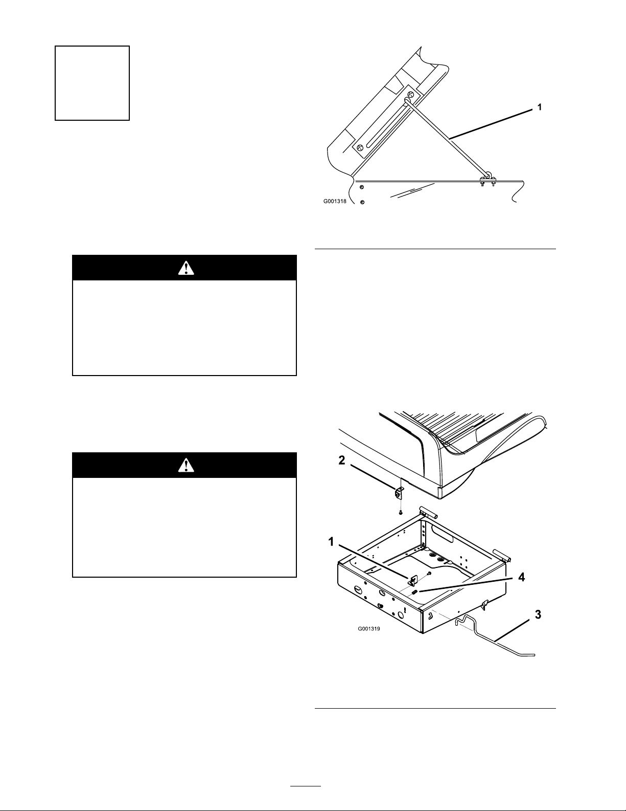
2. Raise the bed. R otate the latc h rod upw ard and
raise the bo x with the other hand.
3. Raise the bo x to its full height; then lo w er it
slightly to eng ag e the prop rod ( Figure 1 ).
A raised bo x could f all and injur e per sons
that ar e w or king beneath it.
Figure 1
1. Prop rod
4. Disconnect the batter y cables from the batter y .
5. R emo v e the brac k et securing the batter y to the
batter y base . Lift the batter y out of the batter y
base .
F or mac hines with Serial n umbers 259999999 and
lo w er :
R emo v e the 2 flang e head screws securing eac h
side of the latc h rod brac k et to the front of the
rear frame ( Figure 2 ).
• Al w ays use the pr op r od to hold the
bo x up bef or e w or king under the bo x.
• R emo v e an y load material fr om the
bo x bef or e raising it.
Figure 2
1. Latch rod bracket 3. Latch rod
2. Latch hook
F or mac hines with Serial n umbers 260000001 and
up:
2
4. Spring
Page 3
R emo v e the 2 flang e head screws securing eac h
side of the latc h rod brac k et to the underside and
front face of the bo x (). R etain all par ts for future
use .
Figure 3
1. Latch rod bracket 3. Flange head screw, inside
front face of box
2. Latch rod 4. Flange head screw,
underside of box
Step
2
Installing the Bed Lift
Parts needed for this step:
1
Lift bracket, upper
4
Flange head screw (5/16 x 3/4 inch)
1
Lift cylinder support
1
Lift actuator
2
U-bolts
6
Flange nut (3/8 inch)
2
Carriage bolts (3/8 x 3/4 inch)
1
Clevis pin, short
1
Cotter pin
Procedure
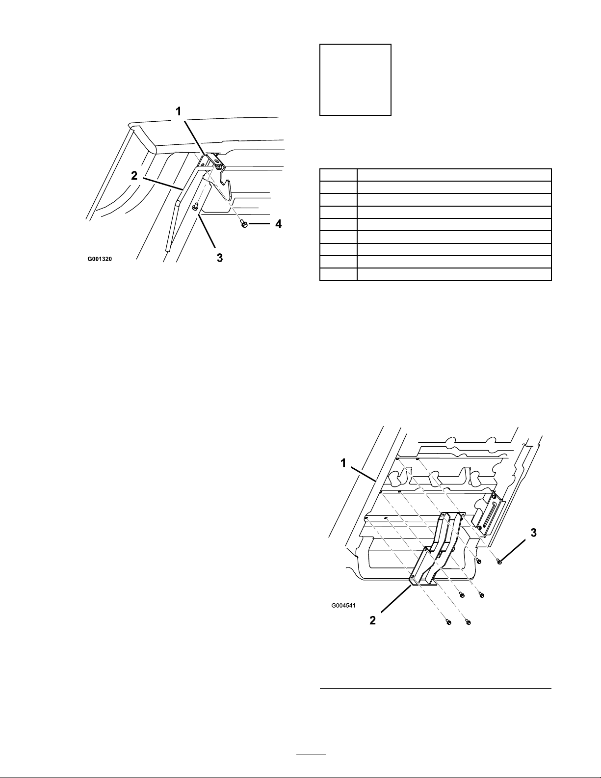
1. R emo v e the screws from the braces on the
underside of the bo x in the positions sho wn
in ( Figure 4 ).
2. Mount the upper lift brac k et to the underside
of the bo x with 6 flang e head screws (5/16
x 3/4 inc h) from loose par ts and remo v ed
previously . P osition the brac k et as sho wn in
Figure 4 .
Figure 4
1. Bed 3. Flange head screw, 5/16 x
2. Upper lift bracket
3/4 inch
3. Loosely mount the lift cylinder suppor t to
the right end of the rear axle with 2 U-bolts
3
Page 4

and 4 flang e n uts (3/4 inc h) while aligning the
mounting holes with the holes in the batter y
tra y ( Figure 5 ).
1. Actuator
2. Lift cylinder support
Figure 6
3. Clevis pin
4. Cotter pin
Figure 5
1. Lift cylinder support 4. U-bolt
2. Right end of the axle 5. Carriage bolt, 3/8 x 3/4
3. Rear frame battery tray 6. Flange nut, 3/4 inch
inch
4. Secure the lift cylinder suppor t to the rear
frame with 2 car riag e bolts (3/8 x 3/4 inc h)
and 2 flang e n uts (3/8 inc h). Tighten the 4
flang e n uts on the U-bolts equally to mak e sure
the brac k et is aligned to the axle . Tighten the
tw o n uts securing the rear of the brac k et to the
rear frame ( Figure 5 ).
5. Mount the bottom end of the lift actuator to
the lift cylinder suppor t with a clevis pin and
cotter pin. P osition the components as sho wn
in Figure 6 .
4
Page 5

Step
5. Install the batter y and connect the cables .
6. Press the switc h upw ard to extend the actuator
rod until it is aligned with the mounting holes
3
in the upper lift brac k et. Secure the rod to the
brac k et with the clevis pin and cotter pin.
Installing the Switch
Parts needed for this step:
1
Switch
1
Thermal fuse, 15 amp
1
Clevis pin, long
1
Cotter pin
Procedure
1. R emo v e the plug from the hole in the right
side of the dash ( Figure 7 ).
Note: If the hole in the dash is in use ,
measure o v er 1/2 inc h (13 mm) and cut
another 0.835 inc h x 1.46 inc h (21 mm x 35
mm) rectangular hole in the dash. Mak e sure
not to damag e any existing components behind
the dash when cutting the hole .
7. R emo v e the screws and clip securing the prop
rod to the frame rail ( Figure 8 ).
Figure 8
1. Prop rod 3. Prop rod bracket
2. Prop rod clip
8. R emo v e the screws securing the prop rod
brac k et to the underside of the bo x. R emo v e
the retainer securing the rod to the brac k et and
remo v e the rod ( Figure 8 ). R etain the prop rod
components for future use .
Note: If the electric bo x lift is ev er remo v ed,
install the prop rod, prop rod clip , and prop
rod brac k et.
Figure 7
1. Plugged hole
2. Switch
3. Cut new hole (if required).
2. Plug the switc h into the har ness connector in
the dash. Inser t the switc h into the hole in the
dash ( Figure 7 ).
3. R emo v e the co v er to expose the fuse bloc k.
Install a new ther mal fuse (15 amp) into the
open slot in the fuse bloc k. Install the co v er .
4. Plug the actuator har ness into the v ehicle
har ness connector , located near the fuse bloc k.
5
Page 6

Operation
Important: W hen a ratcheting noise is
heard, the bo x lift is completel y extended
or r etracted. Do not contin ue pr essing the
s witch.
Raising the Bed
Dri ving the v ehicle with the cargo bo x raised
may cause the v ehicle to tip or r oll easier .
T he bo x str uctur e may become dama ged if
the bo x is raised f or an extended period of
time while operating the v ehicle.
• Onl y operate the v ehicle when the cargo
bo x is do wn.
• After a load has been dumped, lo w er the
cargo bo x.
1. T ur n the ignition k ey to the On position.
2. Push the top of the switc h to raise the bo x.
Lowering the Bed
T he w eight of the bo x may be hea vy . Hands
or other body par ts could be cr ushed.
K eep hands and other body par ts clear when
lo w ering the bo x.
1. Push the bottom of the switc h to lo w er the
bo x.
Note: T he bed will defor m slightly before
the actuator clutc h begins to eng ag e .
Important: W hen a ratcheting noise is
heard, the bo x lift is completel y extended
or r etracted. Do not contin ue pr essing the
s witch.
2. T ur n the ignition k ey to the Off position and
remo v e the k ey .
6
Page 7

Page 8

 Loading...