

Page 1

Sitework Systems Products
®
Dingo
Compact Utility Loader
TX 413
Service Manual
Page 2

ABOUT THIS MANUAL
This service manual was written expressly for Toro service technicians. The Toro company has
made every effort to make the information in this manual complete and correct.
Basic shop safety knowledge and mechanical/electrical skills are assumed. The Table of
Contents lists the systems and the related topics covered in this manual.
For service information on drive systems, please refer to the Hydro-Gear BDP-10 pump
service manual (492-4789) and Parker-Ross TF wheel motor service manual (492-4753).
For information specic to the engines used on this unit, refer to the appropriate engine
manufacturer's service and repair instructions.
2004 and 2005 TX 413 units are covered in this manual. The manual may also be specied for
use on later model products.
The hydraulic power system is precision machinery. Maintain strict cleanliness control during
all stages of service and repair. Cover or cap all hose ends and ttings whenever they are
exposed. Even a small amount of dirt or other contamination can severely damage the system.
We are hopeful that you will nd this manual a valuable addition to your service shop. If you
have any questions or comments regarding this manual, please contact us at the following
address:
The Toro Company
LCB Technical Services
8111 Lyndale Avenue South
Bloomington, MN 55420
The Toro Company reserves the right to change product specications or this manual without
notice.
Copyright© All Rights Reserved
©2009 The Toro Company
Rev. 001
Page 3

REVISIONS
TX 413 SERVICE MANUAL
Revision 000 . . . . . . . . . . . 7/30/05
Revision 001 . . . . . . . . . . . 4/13/09
ii
Rev. 001
TX 413 Service Manual
Page 4

TABLE OF CONTENTS
TX 413 SERVICE MANUAL
Safety Information
General Information . . . . . . . . . . . . . . . . . . . . . . . . . .
Think Safety First . . . . . . . . . . . . . . . . . . . . . . . . . . .
Specifications
General Specifications . . . . . . . . . . . . . . . . . . . . . . . . .
Dimensions . . . . . . . . . . . . . . . . . . . . . . . . . . . . .
Hydraulic System . . . . . . . . . . . . . . . . . . . . . . . . . . .
Electric System . . . . . . . . . . . . . . . . . . . . . . . . . . . .
Track System . . . . . . . . . . . . . . . . . . . . . . . . . . . .
Performance . . . . . . . . . . . . . . . . . . . . . . . . . . . . .
Periodic Maintenance . . . . . . . . . . . . . . . . . . . . . . . . .
Maintenance
Greasing the Traction Unit . . . . . . . . . . . . . . . . . . . . . . . .
Maintaining the Road Wheels . . . . . . . . . . . . . . . . . . . . . .
Hydraulic Reservoir Tank . . . . . . . . . . . . . . . . . . . . . . . .
Replacing the Hydraulic Filter . . . . . . . . . . . . . . . . . . . . . .
Changing the Hydraulic Fluid . . . . . . . . . . . . . . . . . . . . . . .
Checking the Hydraulic Lines . . . . . . . . . . . . . . . . . . . . . .
Vents - Fuel Tank and Hydraulic Tank . . . . . . . . . . . . . . . . . . .
Servicing the Engine, Air Cleaner Replacement, and Spark Plug Servicing . . . . . .
Fuse Block . . . . . . . . . . . . . . . . . . . . . . . . . . . . .
Recommended Maintenance Schedule . . . . . . . . . . . . . . . . . . .
1-2
1-2
2-2
2-2
2-3
2-3
2-4
2-4
2-4
3-2
3-3
3-4
3-5
3-6
3-7
3-7
3-7
3-7
3-8
Engine
Introduction . . . . . . . . . . . . . . . . . . . . . . . . . . . . .
Engine Removal . . . . . . . . . . . . . . . . . . . . . . . . . . .
Engine Installation . . . . . . . . . . . . . . . . . . . . . . . . . .
Choke Cable Installation . . . . . . . . . . . . . . . . . . . . . . . .
Throttle Cable Installation . . . . . . . . . . . . . . . . . . . . . . . .
Fuel Tank Removal . . . . . . . . . . . . . . . . . . . . . . . . . .
Bulkhead Fuel Fitting Replacement . . . . . . . . . . . . . . . . . . .
Fuel Tank Installation . . . . . . . . . . . . . . . . . . . . . . . . .
Starter Service . . . . . . . . . . . . . . . . . . . . . . . . . . . .
Manual Shutoff . . . . . . . . . . . . . . . . . . . . . . . . . . . .
Electrical System
Relay . . . . . . . . . . . . . . . . . . . . . . . . . . . . . . .
Ignition Switch . . . . . . . . . . . . . . . . . . . . . . . . . . . .
Auxiliary Power Neutral Switch . . . . . . . . . . . . . . . . . . . . . .
Regulator/Rectifier . . . . . . . . . . . . . . . . . . . . . . . . . .
Hour Meter . . . . . . . . . . . . . . . . . . . . . . . . . . . . .
Neutral Proximity Switch . . . . . . . . . . . . . . . . . . . . . . . .
Fuel Solenoid or Shutoff Valve . . . . . . . . . . . . . . . . . . . . . .
Electrical Schematic Wiring Diagram . . . . . . . . . . . . . . . . . . . .
4-2
4-2
4-8
4-9
4-10
4-14
4-16
4-17
4-18
4-18
5-2
5-3
5-4
5-4
5-6
5-7
5-8
5-10
TX 413 Service Manual iii
Rev. 001
Page 5

TABLE OF CONTENTS
TX 413 SERVICE MANUAL
Hydraulic System
Hydrostatic Pump Reference Drawing . . . . . . . . . . . . . . . . . . .
Valve Reference Drawings . . . . . . . . . . . . . . . . . . . . . . .
Purging Air Procedures . . . . . . . . . . . . . . . . . . . . . . . . .
Adjusting the Tracking of the Traction Control, Full Forward Position . . . . . . . .
Adjusting the Traction Control Neutral Position . . . . . . . . . . . . . . . .
Hydrostatic Pump (Right Drive) Removal . . . . . . . . . . . . . . . . . .
Hydrostatic Pump Service . . . . . . . . . . . . . . . . . . . . . . . .
Hydrostatic Pump (Right Drive) Installation . . . . . . . . . . . . . . . . .
Hydrostatic Pump (Left Drive) Removal . . . . . . . . . . . . . . . . . .
Hydrostatic Pump Service . . . . . . . . . . . . . . . . . . . . . . . .
Hydrostatic Pump (Left Drive) Installation . . . . . . . . . . . . . . . . . .
Hydrostatic Pump (Right Drive) Hydraulic Fitting Orientation . . . . . . . . . . .
Hydrostatic Pump (Left Drive) Hydraulic Fitting Orientation . . . . . . . . . . . .
Hydrostatic Pump Lever Assembly Removal and Installation . . . . . . . . . . .
Hydraulic Gear Pump Removal . . . . . . . . . . . . . . . . . . . . . .
Hydraulic Gear Pump Installation . . . . . . . . . . . . . . . . . . . . .
Gear Pump Hydraulic Fitting Orientation . . . . . . . . . . . . . . . . . .
Gear Pump Disassembly and Assembly . . . . . . . . . . . . . . . . . .
Gear Pump Disassembly . . . . . . . . . . . . . . . . . . . . . .
Gear Pump Assembly . . . . . . . . . . . . . . . . . . . . . . . .
Wheel Motors . . . . . . . . . . . . . . . . . . . . . . . . . . . .
Hydraulic Schematic Diagram (full page) . . . . . . . . . . . . . . . . . .
Hydraulic Schematic Diagram (double page spread) . . . . . . . . . . . . . .
6-2
6-3
6-4
6-4
6-5
6-6
6-9
6-9
6-12
6-14
6-15
6-17
6-17
6-17
6-18
6-20
6-21
6-21
6-22
6-25
6-28
6-29
6-30, 31
Hydraulic Lift Assembly
Loader Valve Removal . . . . . . . . . . . . . . . . . . . . . . . . .
Lift Valve Installation . . . . . . . . . . . . . . . . . . . . . . . . . .
Auxiliary Valve Removal . . . . . . . . . . . . . . . . . . . . . . . .
Auxiliary Valve Installation . . . . . . . . . . . . . . . . . . . . . . . .
Hydraulic Tilt Cylinder Removal . . . . . . . . . . . . . . . . . . . . . .
Hydraulic Tilt Cylinder Installation . . . . . . . . . . . . . . . . . . . . .
Hydraulic Lift Cylinder Removal . . . . . . . . . . . . . . . . . . . . . .
Hydraulic Lift Cylinder Installation . . . . . . . . . . . . . . . . . . . . .
Loader Arm Assembly Removal . . . . . . . . . . . . . . . . . . . . . .
Loader Arm Assembly Installation . . . . . . . . . . . . . . . . . . . . .
Quick Attachment Assembly Removal . . . . . . . . . . . . . . . . . . .
Loader Arm Bushing Replacement . . . . . . . . . . . . . . . . . . .
Quick Attachment Assembly Installation . . . . . . . . . . . . . . . . . . .
Hydraulic Cylinder Service . . . . . . . . . . . . . . . . . . . . . . .
Hydraulic Cylinder, Lift and Tilt, Disassembly . . . . . . . . . . . . . . . . .
Inspection . . . . . . . . . . . . . . . . . . . . . . . . . . . .
Rebuild . . . . . . . . . . . . . . . . . . . . . . . . . . . . .
7-2
7-4
7-6
7-9
7-12
7-16
7-21
7-25
7-28
7-33
7-37
7-39
7-39
7-40
7-40
7-42
7-42
Rev. 001
TX 413 Service Manualiv
Page 6

TABLE OF CONTENTS
TX 413 SERVICE MANUAL
Hydraulic Lift Assembly cont.
Loader Valve Disassembly and Assembly . . . . . . . . . . . . . . . . . .
Joystick Assembly Removal . . . . . . . . . . . . . . . . . . . . . . .
Joystick Assembly Installation . . . . . . . . . . . . . . . . . . . . . .
Spool Removal . . . . . . . . . . . . . . . . . . . . . . . . . . . .
Spool Assembly . . . . . . . . . . . . . . . . . . . . . . . . . . .
Power Beyond Sleeve-Port . . . . . . . . . . . . . . . . . . . . . . .
Main Relief Valve . . . . . . . . . . . . . . . . . . . . . . . . . . .
Work Port Relief . . . . . . . . . . . . . . . . . . . . . . . . . . .
Auxiliary Spool Valve Disassembly and Assembly . . . . . . . . . . . . . . .
Disassembly . . . . . . . . . . . . . . . . . . . . . . . . . . .
Assembly . . . . . . . . . . . . . . . . . . . . . . . . . . . .
Drive System
Drive Belt Removal . . . . . . . . . . . . . . . . . . . . . . . . . .
Drive Belt Installation . . . . . . . . . . . . . . . . . . . . . . . . .
Track Removal . . . . . . . . . . . . . . . . . . . . . . . . . . . .
Tensioner Wheel Bearing Replacement . . . . . . . . . . . . . . . . .
Bearing Installation . . . . . . . . . . . . . . . . . . . . . . . . .
Track Guide Alignment . . . . . . . . . . . . . . . . . . . . . . . . .
Track Installation . . . . . . . . . . . . . . . . . . . . . . . . . . .
Track Guide Removal . . . . . . . . . . . . . . . . . . . . . . . . .
Road Wheel Bearing Replacement . . . . . . . . . . . . . . . . . . .
Installation of Road Wheel Bearing and Road Wheel Assembly . . . . . . . .
Track Guide Installation . . . . . . . . . . . . . . . . . . . . . . . . .
Wheel Motor Removal . . . . . . . . . . . . . . . . . . . . . . . . .
Wheel Motor Service . . . . . . . . . . . . . . . . . . . . . . . . .
Wheel Motor Installation . . . . . . . . . . . . . . . . . . . . . . . .
Traction Control Handle Assembly Removal . . . . . . . . . . . . . . . . .
Traction Control Handle Assembly Installation . . . . . . . . . . . . . . . .
Brake Assembly Removal . . . . . . . . . . . . . . . . . . . . . . . .
Brake Assembly Installation . . . . . . . . . . . . . . . . . . . . . . .
Idler Assembly Removal . . . . . . . . . . . . . . . . . . . . . . . .
Idler Assembly Installation . . . . . . . . . . . . . . . . . . . . . . .
7-47
7-47
7-49
7-50
7-54
7-58
7-59
7-59
7-60
7-60
7-62
8-2
8-3
8-4
8-6
8-6
8-8
8-9
8-11
8-11
8-13
8-15
8-16
8-18
8-18
8-20
8-22
8-24
8-27
8-29
8-30
Testing
Introduction . . . . . . . . . . . . . . . . . . . . . . . . . . . . .
Flow Testing Hoses . . . . . . . . . . . . . . . . . . . . . . . . . .
Test 1 - Testing Pressure at Flush Face Couplers . . . . . . . . . . . . . . .
Test 2 - Testing Flow at Flush Face Couplers . . . . . . . . . . . . . . . . .
Test 3 - Flow Test at Gear Pump to Loader Valve . . . . . . . . . . . . . . .
Test 4 - Flow Test from Loader Valve to Auxiliary Valve . . . . . . . . . . . . .
Hydrostatic Testing Procedures
Hydrostatic Pump Flow Testing . . . . . . . . . . . . . . . . . . . .
Left Drive System Flow Test . . . . . . . . . . . . . . . . . . . . . . .
Right Drive System Flow Test . . . . . . . . . . . . . . . . . . . . . .
TX 413 Service Manual v
Rev. 001
9-2
9-2
9-4
9-4
9-5
9-5
9-6
9-7
9-9
Page 7

TABLE OF CONTENTS
TX 413 SERVICE MANUAL
Attachments
Auger Removal ...........................................................................................................................10-2
Auger Reassembly .....................................................................................................................10-3
Auger Tooth and Fishtail Shank Removal ..................................................................................10-3
Fishtail Shank Installation ...........................................................................................................10-4
Auger Tooth Replacement ..........................................................................................................10-5
Disassemble Auger Power Head ................................................................................................10-5
Hydraulic Motor Removal ...........................................................................................................10-7
Shaft Removal ............................................................................................................................10-8
Remove Power Head from Frame Assembly ........................................................................... 10-11
Reassemble Power Head into Frame Assembly ...................................................................... 10-12
Reassemble Auger Power Head ..............................................................................................10-14
Trencher ...................................................................................................................................10-20
Trencher Chain and Boom Removal ........................................................................................10-21
Nose Roller Removal .........................................................................................................10-23
Reassemble the Nose Roller .............................................................................................10-25
Motor Removal .........................................................................................................................10-26
Trencher Shaft Removal ....................................................................................................10-26
Reassemble Trencher ........................................................................................................10-29
Hydraulic Troubleshooting
Fluids .......................................................................................................................................... 11-2
Hydraulic Fluids ...................................................................................................................11-2
Viscosity ............................................................................................................................... 11-2
Excessive Fluid Temperature ............................................................................................... 11-2
Foaming Fluid ...................................................................................................................... 11-3
Hydraulic Fluid Dirty/Milky ................................................................................................... 11-3
Discolored/Burned Fluid .......................................................................................................11-3
Operational Troubleshooting ...................................................................................................... 11-3
Loss of Hydraulic Function ..................................................................................................11-3
Operational Troubleshooting cont...............................................................................................11-4
Loss of Hydraulic Function cont. ......................................................................................... 11-4
Erratic Operation .................................................................................................................. 11-4
Slow Operation ....................................................................................................................11-4
Pumps ........................................................................................................................................11-5
Pump Troubleshooting ......................................................................................................... 11-5
Pumps cont................................................................................................................................. 11-6
Noisy Pump ..........................................................................................................................11-6
Leaky Pump ......................................................................................................................... 11-6
Wheel Motors .............................................................................................................................11-6
Valves ......................................................................................................................................... 11-7
Bypass Valve ....................................................................................................................... 11-7
Relief Valve Troubleshooting ...............................................................................................11-7
Spool Valve Troubleshooting ...............................................................................................11-7
Control Valve Leaks ............................................................................................................. 11-7
Cylinders/Loader Arms ............................................................................................................... 11-8
Hydraulic Cylinders .............................................................................................................. 11-8
Cylinder Leaks ..................................................................................................................... 11-8
Loader Arm Drops in Neutral ............................................................................................... 11-8
vi
Rev. 001
TX 413 Service Manual
Page 8
SAFETY INFORMATION
TX 413 Service Manual
Rev. 000
1-1
Page 9

SAFETY INFORMATION
General Information
This symbol means WARNING
or PERSONAL SAFETY
INSTRUCTION - read the
instruction because it has to
do with your safety. Failure to
comply with the instruction may
result in personal injury or even death.
This manual is intended as a service and
repair manual only. The safety instructions
provided herein are for troubleshooting,
service, and repair of the Sitework Systems
TX 413 compact utility loader.
The TX 413 loader and attachment
operator's manuals contain safety
information and operating tips for safe
operating practices. Operator's manuals are
available through your Toro parts source or:
Avoid burns...
Do not touch the engine, muffl er, or
other components which may increase in
temperature during operation, while the
unit is running or shortly after it has been
running.
Avoid fi res and explosions...
Avoid spilling fuel and never smoke while
working with any type of fuel or lubricant.
Wipe up any spilled fuel or oil immediately.
Never remove the fuel cap or add fuel when
the engine is running. Always use approved,
labeled containers for storing or transporting
fuel and lubricants.
Avoid asphyxiation...
Never operate an engine in a confi ned area
without proper ventilation.
The Toro Company
Publications Department
8111 Lyndale Avenue South
Bloomington, MN 55420
Think Safety First
Avoid unexpected starting of engine...
Always turn off the engine and disconnect
the spark plug wire(s) before cleaning,
adjusting, or repair.
Avoid lacerations and amputations...
Stay clear of all moving parts whenever the
engine is running. Treat all normally moving
parts as if they were moving whenever the
engine is running or has the potential to start.
Avoid injury from batteries...
Battery acid is poisonous and can cause
burns. Avoid contact with skin, eyes, and
clothing. Battery gases can explode. Keep
cigarettes, sparks, and fl ames away from the
battery.
Avoid injury due to inferior parts...
Use only original equipment parts to ensure
that important safety criteria are met.
Avoid injury to bystanders...
Always clear the area of bystanders before
starting or testing powered equipment.
Avoid injury due to projectiles...
Always clear the area of sticks, rocks, or
any other debris that could be picked up and
thrown by the powered equipment.
1-2
TX 413 Service ManualRev. 000
Page 10

Avoid modifi cations...
Never alter or modify any part unless it is a
factory approved procedure.
Avoid unsafe operation...
Always test the safety interlock system
after making adjustments or repairs on the
machine. Refer to the Electrical section in
this manual for more information.
Hydraulics Safety
• Inspect all hydraulic line connectors and
fi ttings. Make sure all hydraulic hoses and
lines are in good condition before applying
pressure to the system.
SAFETY INFORMATION
• Keep body and hands away from pin hole
leaks or nozzles that eject high pressure
hydraulic fl uid. Use cardboard or paper to
fi nd hydraulic leaks. Hydraulic fl uid escaping
under pressure can penetrate the skin and
cause injury. Fluid accidentally injected into
the skin must be surgically removed within
a few hours by a doctor or gangrene may
occur.
• Before disconnecting or performing any
work on the hydraulic system, lower the
loader arm/attachment to the ground and
stop the engine so all pressure is relieved.
• Be sure you understand a service
procedure before working on the machine.
TX 413 Service Manual
Rev. 000
1-3
Page 11

SAFETY INFORMATION
THIS PAGE INTENTIONALLY LEFT BLANK.
1-4
TX 413 Service ManualRev. 000
Page 12
SPECIFICATIONS
TX 413 Service Manual
Rev. 000
2-1
Page 13
SPECIFICATIONS
Special Tools
• Hydraulic Flow & Pressure Tester (Hydro-Gear BDP) Bi-directional Flow Test Kit (P/N 70661) or
equivalent
• 15º/60º Offset Open End Wrench, 1/8" and 15/16"
• Torque Wrenches - nominal torque ranges, plus one capable of 300 ft-lbs. (407 Nm)
• Multimeter
General Specifications
Item Specification
Engine Honda Model GX390 13 horsepower, 4-cycle, air cooled, single cylinder, overhead
valves, 12 VDC solenoid shift starter, 10 amp alternator, and low oil shut down.
RPM Setting No-load Speed - 3600 rpm + 150 rpm
Low Idle Speed - 1450 rpm + 150 rpm
Spark Plug NGK BPR6ES, Denso W20EPR-U or equivalent. Air Gap: 0.030 inch (0.76mm).
Oil Capacity 1.16 Quarts (1.1 liter)
Fuel Tank 3 Gallons (11.4 liter)
Fuel shut off Frame mounted electric fuel shut off
Dimensions:
Item Specification
Overall Length (without Bucket) 66.1" (167cm)
Overall Length (with Bucket) 86.7" (220cm)
Overall Width (without Bucket) 33.7" (85.6cm)
Overall Width (with Bucket) 34.5" (87.6cm)
Overall Machine Height (Bucket
Lowered)
Overall Operating Height (Fully
Raised Bucket)
Wheel Base 31.1" (78.9cm)
Ground Clearance (Maximum) 6.1" (15.5cm)
Ground Clearance (Minimum) 3.8" (9.7cm)
Dump Angle 45°
Bucket Roll Back (Ground Position) 25.2°
Bucket Roll Back (Carry Position) 25.2°
42.5" (107.9cm)
76.4" (194cm)
2-2
Rev. 000
TX 413 Service Manual
Page 14

SPECIFICATIONS
Hydraulic System:
Item Specification
Gear Pump Single section 6.9 gpm (26.12 liter/min) gear pump powers the loader and auxiliary
hydraulic systems.
Loader Valve Two-spool mono-block valve controls loader functions via a single lever joystick. The
valve has a power beyond circuit which feeds the auxiliary circuit.
Main Relief Setting: 2650 psi (182.71 bar)
Work Port Reliefs: 2030 psi (140 bar) for the bucket curl and loader lower circuit.
Auxiliary Valve Single spool valve controls the auxiliary flow to the Dingo TX attachments. Flow is
received via power beyond circuit in loader valve. The valve is actuated by a two-stepmotion lever for forward and reverse flows. Relief is provided by loader valve at 2650 psi
(182.7 bar).
Hydrostatic Pump The traction circuit is powered by dual hydrostatic pumps in a closed loop system. The
pumps have a service bypass valves for towing and have shock valves to limit circuit
pressure spikes. The Hydro-Gear BDP-10A pumps are mechanically actuated by the
patented Dingo TX traction control system.
Pump Displacement: .61 in3/rev (10cm3/rev)
Pump Speed: 3600 rpm
Shock Valve Relief: 2320 psi (160 bar)
Wheel Motors Two Parker-Ross TF hydraulic motors directly drive the track wheels.
Displacement: 24.7 in3/rev (40.4cm3/rev)
Mounting: 4-bolt through frame
Lift Cylinders The lift circuit has a single hydraulic cylinder that control loader height.
Working Pressure: 2650 psi (182.7 bar)
Dump Cylinders The Quick-Attach angle is controlled by a single hydraulic cylinder.
Working Pressure: 2650 psi (182.7 bar)
Tank The hydraulic tank is a fabricated weldment integrated into the main frame. The tank
has a cleanout access, stainless screen at the fill port, and a remote breather connected
via hose.
Capacity: 10 gallon (37.8 liter)
Filter 10 micron spin-on filter in gear return circuit
Electric System:
Item Specification
Battery 12 volt, BCI group 55 battery with 585 CCA
Hour Meter Frame mounted with Service Interval icon.
Fuel Shut Off 12 VDC ignition coil type
Ignition Ignition switch is panel mounted with STOP-RUN-START positions.
Fuses The machine has a fuse block with 3 separate fuses, 10 amp, 25 amp,
and 30 amp circuits.
TX 413 Service Manual
Rev. 000
2-3
Page 15

SPECIFICATIONS
Track System:
Item Specification
Track The tracks are Kevlar reinforced, endless rubber rings with 28 internal lugs. The outer
tread on the tracks is a turf-friendly S-shaped pattern with pitched crosscuts.
Track Width: 5.88 inches (14.9cm)
Track Pitch: 3.45 inches (8.8cm)
Drive Wheel The drive wheels are single-piece, austempered ductile iron, “squirrel cage” castings.
Wheel Diameter: 11.63 inches (29.5cm)
Road Wheels Constant track ground pressure is maintained by 20 ductile iron road wheels. The road
wheels each have a sealed bearing that are protected by a secondary dirt seal on the
inside and a gasketed steel cap on the outside.
Performance:
Item Specification
Tip Capacity 1200 lbs. (544.3kg)
Operating Capacity SAE J818 rating 35% tip capacity 420 lb (190.5kg)
SAE J818 rating 50% tip capacity 600 lb (272.2kg)
Speed Forward 0 - 3 mph (0 - 4.8km/hr)
Reverse 0 - 1.5 mph (0 - 2.4km/hr)
Weight 1340 lbs. (607.8kg) (traction unit only)
1440 lbs. (653.2kg) (with Dingo TX bucket)
Periodic Maintenance Items:
Item Specification Maintenance Interval
Grease Lithium Base NLGI2 (National Lubricating
Grease Institute.)
Hydraulic Oil 10w30 CH4 rating - 10 gal. (37.8 liters) Check daily - change at 400 hrs.
Hydraulic Filter Spin on Initially, 8 hrs., then every 200 hrs.;
Engine Oil No filter, 10w30, SJ Rating, 1.16 qts (1.1 liters) /
5w-20 or 5w-30 below 32º F (0º C)
Engine Air Filter Paper element with foam prefilter Check every 50 hrs.; more often
Note: Refer to Section 2 and the TX 413 and engine operator manuals for additional information.
Every 8 hrs. or after every washing
more often when used in dusty,
dirty conditions
Check daily - change at 100 hrs.;
more often when used in dusty,
dirty conditions.
when used in dusty, dirty conditions
2-4
Rev. 000
TX 413 Service Manual
Page 16
SPECIFICATIONS
Torque Specifications
Recommended fastener torque values are listed in the
following tables. For critical applications, as
determined by Toro, either the recommended torque or
a torque that is unique to the application is clearly
identified and specified in the service manual.
These torque specifications for the installation and
tightening of fasteners shall apply to all fasteners which
2
do not have a specific requirement identified in the
service manual. The following factors shall be
considered when applying torque: cleanliness of the
fastener, use of a thread sealant (Loctite), degree of
lubrication on the fastener, presence of a prevailing
torque feature, hardness of the surface underneath of
the fastener’s head, or similar condition which affects
the installation.
As noted in the following tables, torque values should
be reduced by 25% for lubricated fasteners to
achieve the similar stress as a dry fastener. Torque
values may also have to be reduced when the fastener
is threaded into aluminum or brass. The specific
torque value should be determined based on the
aluminum or brass material strength, fastener size,
length of thread engagement, etc.
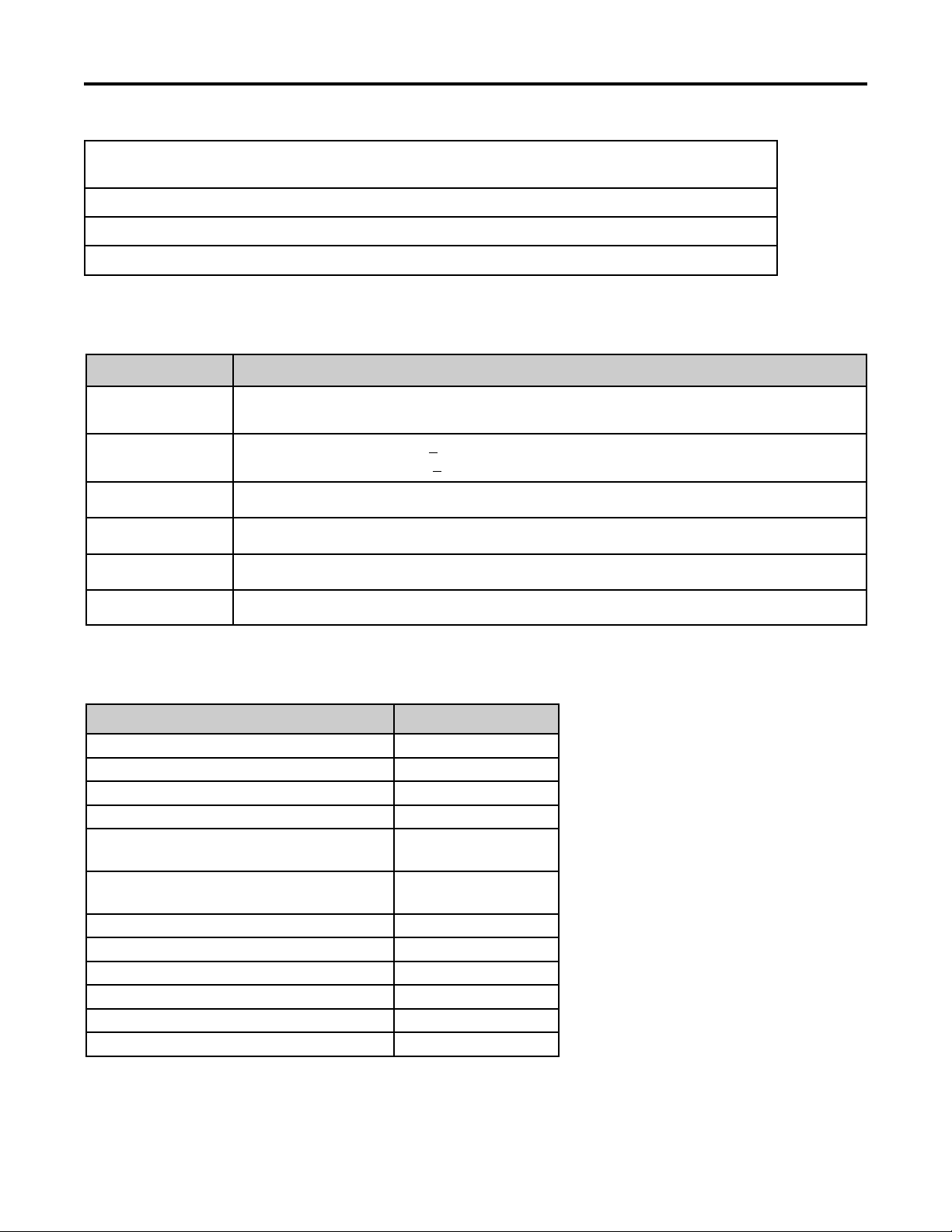
Fastener Identification
Inch Series Bolts and Screws
(A) Grade 1
(B) Grade 5
Figure 1
(C) Grade 8
The standard method of verifying torque shall be
performed by marking a line on the fastener (head or
nut) and mating part, then back off fastener 1/4 of a
turn. Measure the torque required to tighten the
fastener until the lines match up.
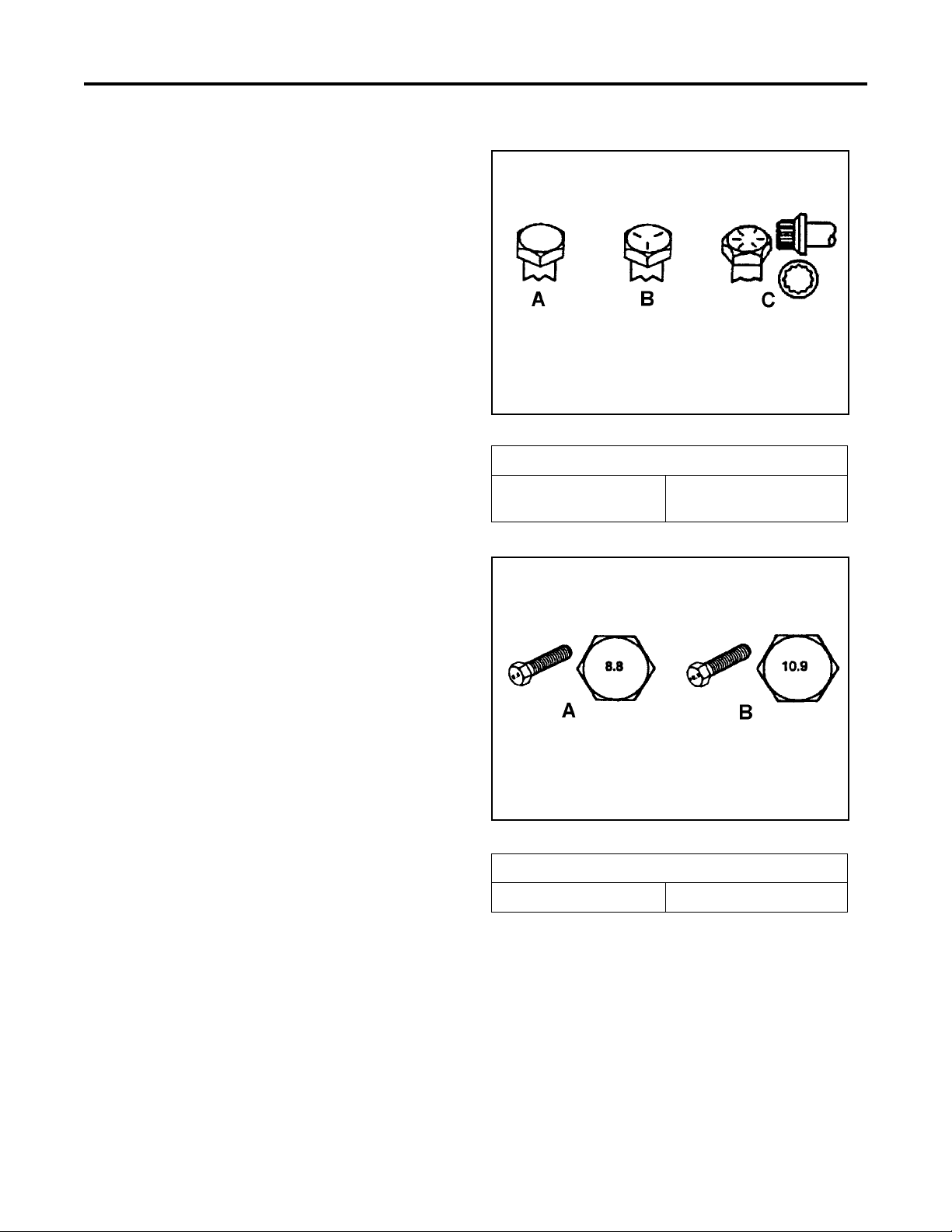
Figure 2
Metric Bolts and Screws
(A) Class 8.8 (B) Class 10.9
TX 413 Service Manual
Rev. 000
2-5
Page 17

SPECIFICATIONS
Standard Torque for Dry, Zinc Plated, and Steel Fasteners (Inch Series)
Grade 1, 5, &
Thread Size
# 6 - 32 UNC
# 6 - 40 UNF 17 ± 2 190 ± 20 25 ± 2 280 ± 20
# 8 - 32 UNC
# 8 - 36 UNF 31 ± 3 350 ± 30 43 ± 4 31 ± 3
# 10 - 24 UNC
#10 - 32 UNF 48 ± 4 540 ± 45 68 ± 6 765 ± 70
1/4 - 20 UNC 48 ± 7 53 ± 7 599 ± 79 100 ± 10 1125 ± 100 140 ± 15 1580 ± 170
1/4 - 28 UNF 53 ± 7 65 ± 10 734 ± 113 115 ± 10 1300 ± 100 160 ± 15 1800 ± 170
5/16 - 18 UNC 115 ± 15 105 ± 17 1186 ± 169 200 ± 25 2250 ± 280 300 ± 30 3390 ± 340
5/16 - 24 UNF 138 ± 17 128 ± 17 1446 ± 192 225 ± 25 2540 ± 280 325 ± 30 3670 ± 340
3/8 - 16 UNC 16 ± 2 16 ± 2 22 ± 3 30 ± 3 41 ± 4 43 ± 4 58 ± 5
3/8 - 24 UNF 17 ± 2 18 ± 2 24 ± 3 35 ± 3 47 ± 4 50 ± 4 68 ± 5
7/16 - 14 UNC 27 ± 3 27 ± 3 37 ± 4 50 ± 5 68 ± 7 70 ± 7 68 ± 9
7/16 - 20 UNF 29 ± 3 29 ± 3 39 ± 4 55 ± 5 75 ± 7 77 ± 7 104 ± 9
1/2 - 13 UNC 30 ± 3 48 ± 7 65 ± 9 75 ± 8 102 ± 11 105 ± 10 142 ± 14
1/2 - 20 UNF 32 ± 3 53 ± 7 72 ± 9 85 ± 8 115 ± 11 120 ± 10 163 ± 14
5/8 - 11 UNC 65 ± 10 88 ± 12 119 ± 16 150 ± 15 203 ± 20 210 ± 20 285 ± 27
5/8 - 18 UNF 75 ± 10 95 ± 15 129 ± 20 170 ± 15 230 ± 20 240 ± 20 325 ± 27
3/4 - 10 UNC 93 ± 12 140 ± 20 190 ± 27 265 ± 25 359 ± 34 374 ± 35 508 ± 47
3/4 - 16 UNF 115 ± 15 165 ± 25 224 ± 34 300 ± 25 407 ± 34 420 ± 35 569 ± 47
7/8 - 9 UNC 140 ± 20 225 ± 25 305 ± 34 430 ± 45 583 ± 61 600 ± 60 813 ± 81
7/8 - 14 UNF 155 ± 25 260 ± 30 353 ± 41 475 ± 45 644 ± 61 660 ± 60 895 ± 81
8 with Thin
Height Nuts
In-lb In-lb N-cm In-lb N-cm In-lb N-cm
10 ± 2 13 ± 2 147 ± 23
13 ± 2 25 ± 5 282 ± 30
18 ± 2 30 ± 5 339 ± 56
ft-lb ft-lb N-m ft-lb N-m ft-lb N-m
SAE Grade 1 Bolts, Screws,
Studs, & Sems with Regular
Height Nuts (SAE J995
Grade 2 or Stronger Nuts)
SAE Grade 5 Bolts, Screws,
Studs, & Sems with Regular
Height Nuts (SAE J995
Grade 2 or Stronger Nuts)
15 ± 2 170 ± 20 23 ± 2 260 ± 20
29 ± 3 330 ± 30 41 ± 4 460 ± 45
42 ± 4 475 ± 45 60 ± 6 674 ± 70
SAE Grade 8 Bolts, Screws,
Studs, & Sems with Regular
Height Nuts (SAE J995
Grade 2 or Stronger Nuts)
Note: Reduce torque values listed in the table above
by 25% for lubricated fasteners. Lubricated fasteners
are defined as threads coated with a lubricant such as
oil, graphite, or thread sealant such as Loctite.
Note: Torque values may have to be reduced when
installing fasteners into threaded aluminum or brass.
The specific torque value should be determined based
on the fastener size, the aluminum or base material
strength, length of thread engagement, etc.
2-6
Note: The nominal torque values listed above for
Grade 5 and 8 fasteners are based on 75% of the
minimum proof load specified in SAE J429. The
tolerance is approximately
value. Thin height nuts include jam nuts.
± 10% of the nominal torque
TX 413 Service ManualRev. 000
Page 18

SPECIFICATIONS
Standard Torque for Dry, Zinc, and Steel Fasteners (Metric Fasteners)
Class 8.8 Bolts, Screws, and Studs with
Thread Size
M5 X 0.8 57 ± 5 in-lb 640 ± 60 N-cm 78 ± 7 in-lb 885 ± 80 N-cm
M6 X 1.0 96 ± 9 in-lb 1018 ± 100 N-cm 133 ± 13 in-lb 1500 ± 150 N-cm
M8 X 1.25 19 ± 2 ft-lb 26 ± 3 N-m 27 ± 2 ft-lb 36 ± 3 N-m
M10 X 1.5 38 ± 4 ft-lb 52 ± 5 N-m 53 ± 5 ft-lb 72 ± 7 N-m
M12 X 1.75 66 ± 7 ft-lb 90 ± 10 N-m 92 ± 9 ft-lb 125 ± 12 N-m
M16 X 2.0 166 ± 15 ft-lb 225 ± 20 N-m 229 ± 22 ft-lb 310 ± 30 N-m
M20 X 2.5 325 ± 33 ft-lb 440 ± 45 N-m 450 ± 37 ft-lb 610 ± 50 N-m
Note: Reduce torque values listed in the table above
by 25% for lubricated fasteners. Lubricated fasteners
are defined as threads coated with a lubricant such as
oil, graphite, or thread sealant such as Loctite.
Regular Height Nuts
(Class 8 or Strong Nuts)
Note: The nominal torque values listed above are
based on 75% of the minimum proof load specified in
SAE J1199. The tolerance is approximately
the nominal torque value. Thin height nuts include jam nuts.
Class 10.9 Bolts, Screws, and Studs with
Regular Height Nuts (
Class 10 or Strong Nuts)
Note: Torque values may have to be reduced when
installing fasteners into threaded aluminum or brass.
The specific torque value should be determined based
on the fastener size, the aluminum or base material
strength, length of thread engagement, etc.
± 10% of
TX 413 Service Manual
Rev. 000
2-7
Page 19

SPECIFICATIONS
Other Torque Specifications
SAE Grade 8 Steel Set Screws
Recommended Torque
Thread Size
Square Head Hex Socket
1/4 - 20 UNC 140 ± 20 in-lb 73 ± 12 in-lb
5/16 - 18 UNC 215 ± 35 in-lb 145 ± 20 in-lb
3/8 - 16 UNC 35 ± 10 ft-lb 18 ± 3 ft-lb
1/2 - 13 UNC 75 ± 15 ft-lb 50 ± 10 ft-lb
Thread Cutting Screws
(Zinc Plated Steel)
Type 1, Type 23, or Type F
Thread Size Baseline Torque*
No. 6 - 32 UNC 20 ± 5 in-lb
No. 8 - 32 UNC 30 ± 5 in-lb
Wheel Bolts and Lug Nuts
Thread Size Recommended Torque**
7/16 - 20 UNF
Grade 5
1/2 - 20 UNF
Grade 5
M12 X 1.25
Class 8.8
M12 X 1.5
Class 8.8
65 ± 10 ft-lb 88 ± 14 N-m
80 ± 10 ft-lb 108 ± 14 N-m
80 ± 10 ft-lb 108 ± 14 N-m
80 ± 10 ft-lb 108 ± 14 N-m
** For steel wheels and non-lubricated fasteners.
Thread Cutting Screws
(Zinc Plated Steel)
Thread
Size
No. 6 18 20 20 ± 5 in-lb
No. 8 15 18 30 ± 5 in-lb
Threads per Inch
Baseline Torque*
Type A Type B
No.10 - 24 UNC 38 ± 7 in-lb
1/4 - 20 UNC 85 ± 15 in-lb
5/16 - 18 UNC 110 ± 20 in-lb
3/8 - 16 UNC 200 ± 100 in-lb
Conversion Factors
in-lb X 11.2985 - N-cm
ft-lb X 1.3558 = N-m
No. 10 12 16 38 ± 7 in-lb
No. 12 11 14 85 ± 15 in-lb
* Hole size, material strength, material thickness and
finish must be considered when determining specific
torque values. All torque values are based on nonlubricated fasteners.
N-cm X - 0.08851 = in-lb
N-cm X 0.73776 - ft-lb
2-8
TX 413 Service ManualRev. 000
Page 20

SPECIFICATIONS
Equivalents and Conversions
Decimal and Millimeter Equivalents
Fractions Decimals mm Fractions Decimals mm
1/64 0.015625 0.397 33/64 0.515625 13.097
1/32 0.03125 0.794 16/32 0.53125 13.484
3/64 0.046875 1.191 35/64 0.546875 13.891
1/16 0.0625 1.588 9/16 0.5625 14.288
5/64 0.078125 1.984 37/64 0.578125 14.684
3/32 0.9375 2.381 19/32 0.59375 15.081
1/8 0.1250 3.175 5/8 0.6250 15.875
9/64 0.140625 3.572 41/64 0.640625 16.272
5/32 0.15625 3.969 21/32 0.65625 16.669
11/64 0.171875 4.366 43/64 0.671875 17.066
3/16 0.1875 4.762 11/16 0.6875 17.462
13/64 0.203125 5.159 45/64 0.703125 17.859
7/32 0.21875 5.556 23/32 0.71875 18.256
15/64 0.234375 5.953 47/64 0.734375 18.653
1/4 0.2500 6.350 3/4 0.7500 19.050
17/64 0.265625 6.747 49/64 0.765625 19.447
9/32 0.28125 7.144 25/32 0.78125 19.844
19/64 0.296875 7.541 51/64 0.796875 20.241
5/16 0.3125 7.541 13/16 0.8125 20.638
21/64 0.328125 8.334 53/64 0.828125 21.034
11/32 0.34375 8.731 27/32 0.84375 21.431
23/64 0.359375 9.128 55/64 0.859375 21.828
3/8 0.3750 9.525 7/8 0.8750 22.225
25/64 0.390625 9.922 57/64 0.890625 22.622
13/32 0.40625 10.319 29/32 0.90625 23.019
27/64 0.421875 10.716 59/64 0.921875 23.416
7/16 0.4375 11.112 15/16 0.9375 23.812
29/64 0.453125 11.509 61/64 0.953125 24.209
15/32 0.46875 11.906 31/32 0.96875 24.606
31/64 0.484375 12.303 63/64 0.984375 25.003
1/2 0.5000 12.700 1 1.000 25.400
1 mm = 0.03937 in. 0.001 in. = 0.0254 mm
TX 413 Service Manual
Rev. 000
2-9
Page 21

SPECIFICATIONS
Linear
Measurement
Area
Vol ume
Weight
Pressure
Work
Liquid Volume
Liquid Flows
Temper ature
U.S. to Metric Conversions
To Convert Into Multiply By
Miles
Yar ds
Feet
Feet
Inches
Inches
Inches
Square Miles
Square Feet
Square Inches
Acre
Cubic Yards
Cubic Feet
Cubic Inches
Tons (Short)
Pounds
Ounces
Pounds/Sq. In. Kilopascal
Foot-pounds
Foot-pounds
Inch-pounds
Quarts
Gallons
Gallons/Minute Liters/Minute
Fahrenheit Celsius
Kilometers
Meters
Meters
Centimeters
Meters
Centimeters
Millimeters
Square Kilometers
Square Meters
Square Centimeters
Hectare
Cubic Meters
Cubic Meters
Cubic Centimeters
Metric Tons
Kilograms
Grams
Newton-Meters
Kilogram-Meters
Kilogram-Centimeters
Liters
Liters
1.609
0.9144
0.3048
30.48
0.0254
2.54
25.4
2.59
0.0929
6.452
0.4047
0.7646
0.02832
16.39
0.9078
0.4536
28.3495
6.895
1.356
0.1383
1.152144
0.9463
3.785
3.785
1. Subtract 32°
2. Multiply by 5/9
2-10
TX 413 Service ManualRev. 000
Page 22
MAINTENANCE
TX 413 Service Manual
Rev. 000
3-1
Page 23
MAINTENANCE
Greasing the Traction Unit
Grease all pivot joints every 8 operating hours and
immediately after every washing.
Grease Type: Lithium based NLGI2
1. Lower the loader arm and stop the engine.
Remove the key from the ignition switch.
2. Clean the grease fittings with a rag.
3. Connect grease gun to each fitting and pump
grease into the fittings until grease begins to ooze
out of the bearings (approximately 3 pumps).
4. Wipe any excess grease.
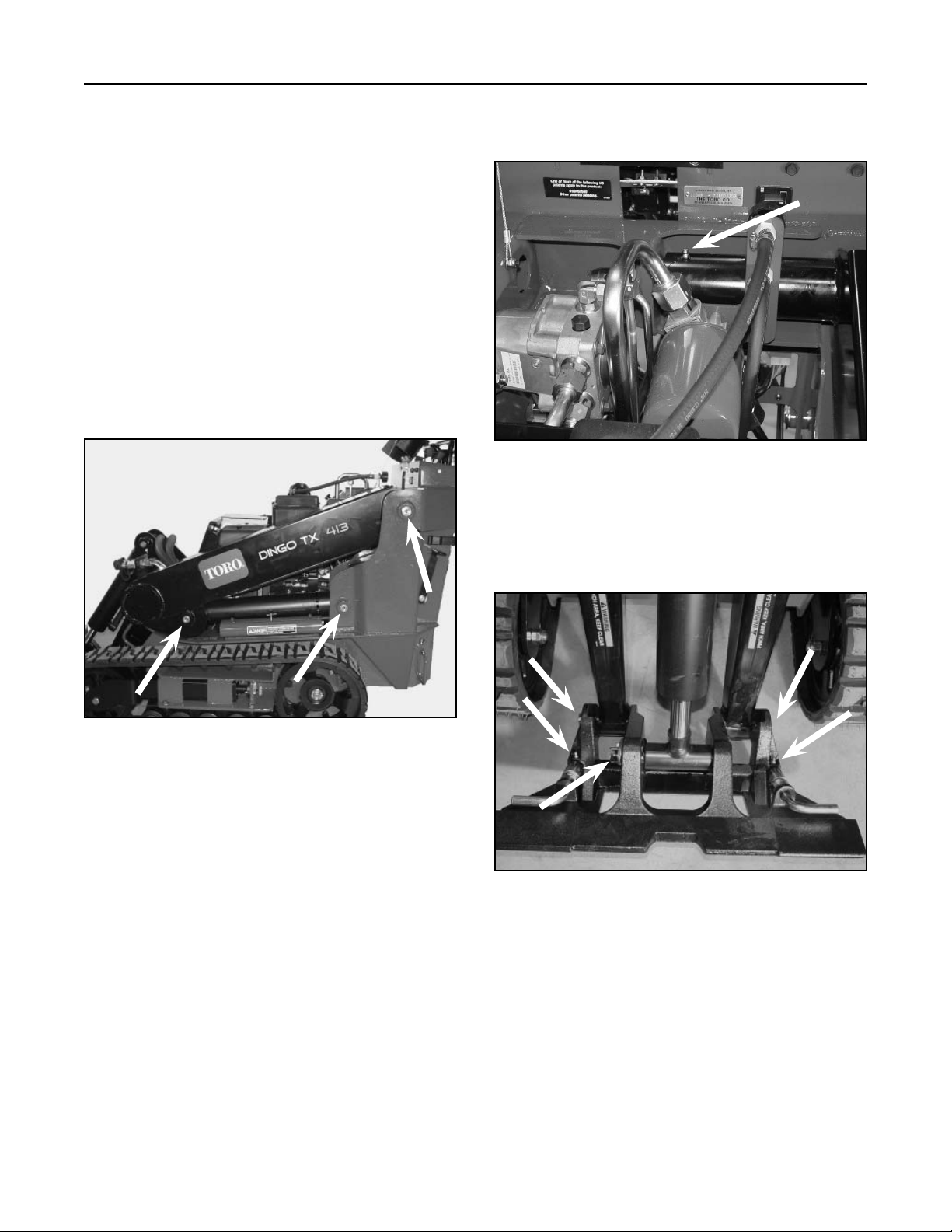
There are 11 grease fittings on the TX413: (3) are
located on the left side (Fig. 001).
(1) is located under the hood for the loader arm
assembly (Fig. 002).
Figure 002 DSC-0766
(5) are located in the front on the quick attachment
assembly and the front loader arm assembly (Fig.
003).
Figure 001 DSC-0764
3-2
Rev. 000
Figure 003 DSC-0767
TX 413 Service Manual
Page 24
MAINTENANCE
(2) are located on the right side of the unit (Fig. 004).
Figure 004 DSC-0769
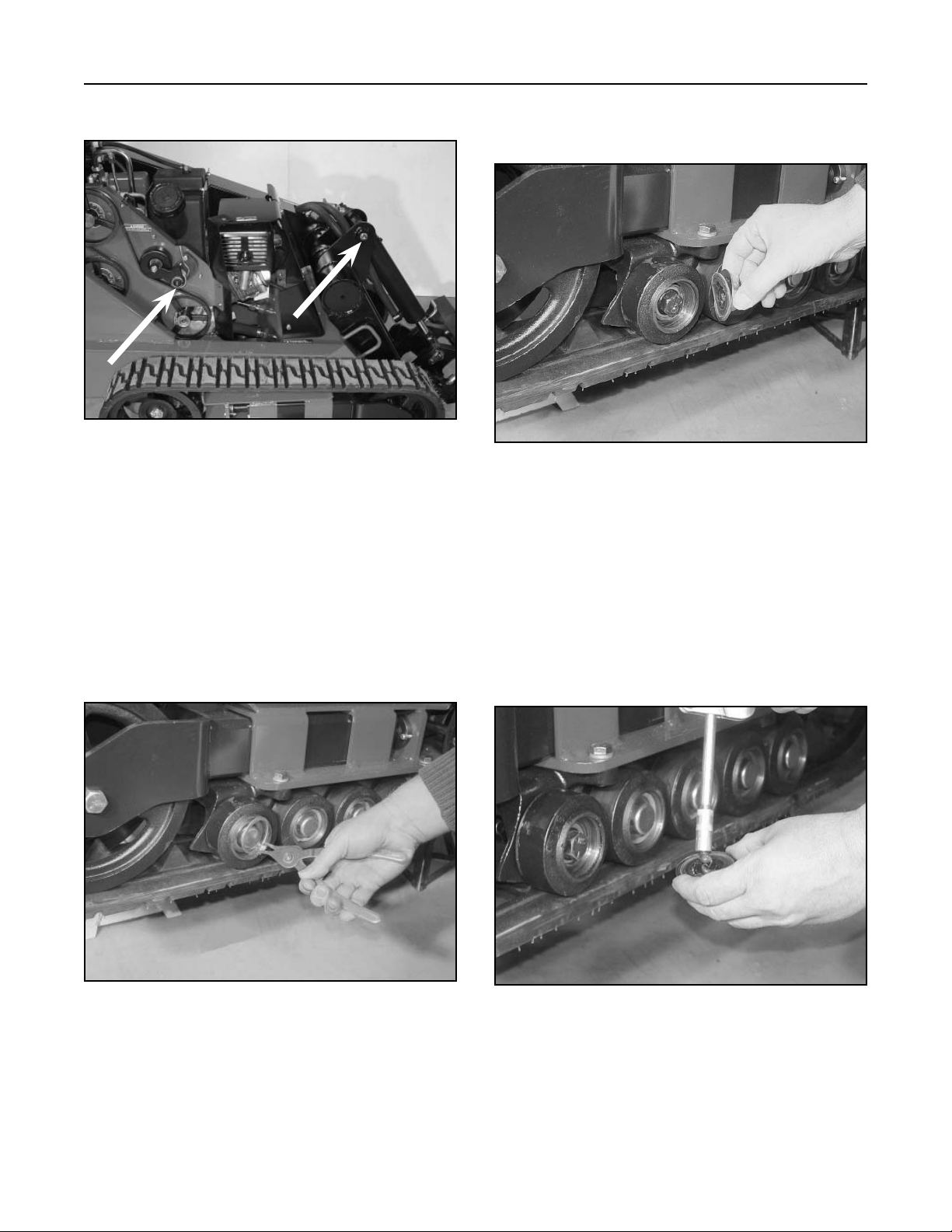
Maintaining the Road Wheels
1. Remove the tracks; refer to Track Removal, page
8-4.
Note: Remove the tracks only when the inner
wheels or the complete tray of wheels
needs maintenance.
2. Remove the snap ring and cap from a road wheel
(Fig. 005).
3. Remove the wheel bearing cap with seal (Figure
006).
Figure 006 DSC-0822
4. Ensure that the road wheel turns smoothly on the
bearing. If it does not turn smoothly or spin freely,
replace the bearing; refer to Road Wheel Bearing
Replacement, page 8-10.
5. Check the grease under the cap and around the
gasket. If it is dirty, gritty, or depleted, clean out
all of the grease, replace the gasket, and fill the
head of the cap with new grease (Fig. 007).
Figure 005 DSC-0821
TX 413 Service Manual
Rev. 000
Figure 007 DSC-0835
3-3
Page 25
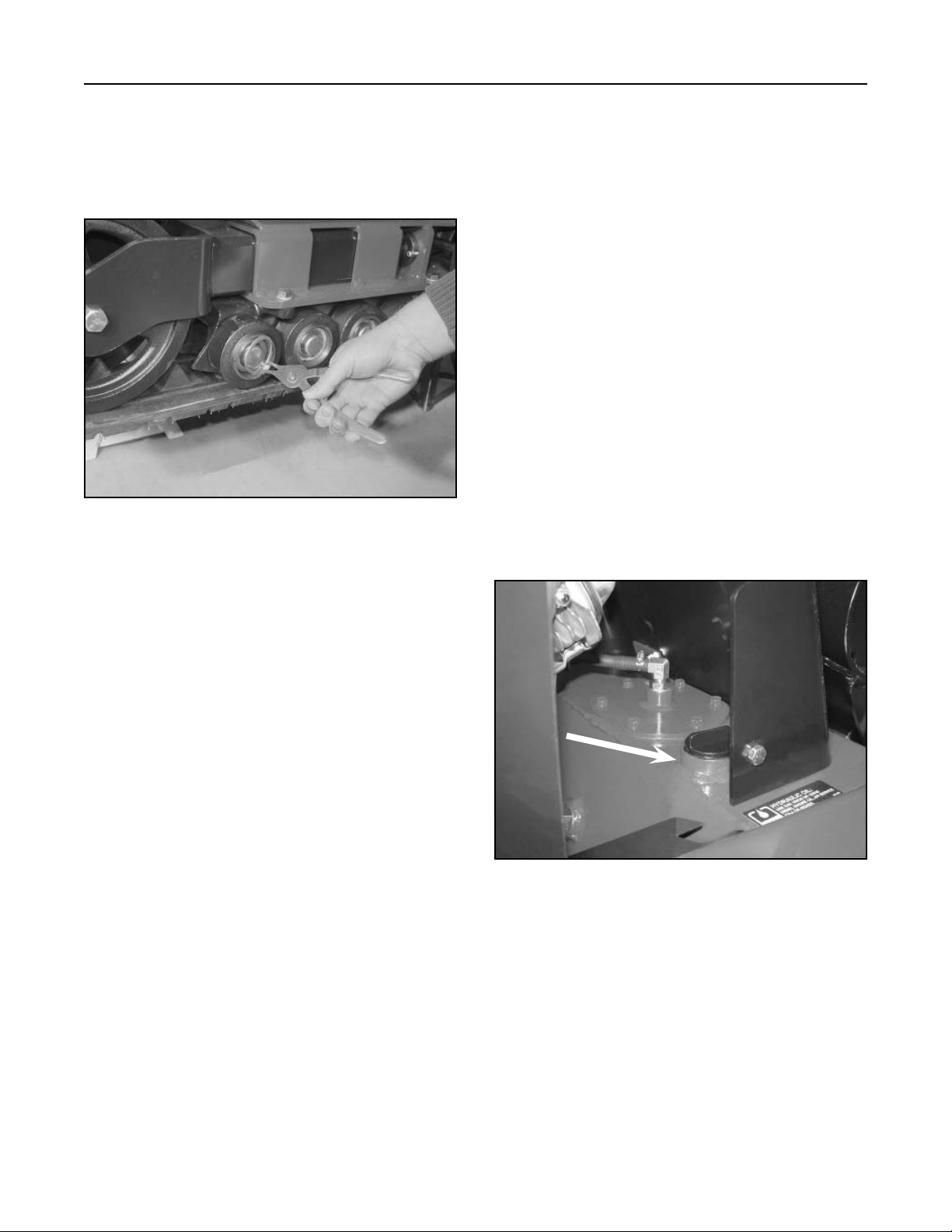
MAINTENANCE
6. Place the greased road wheel cap and seal over
the bolt head.
7. Secure the road wheel cap with the snap ring
(Fig. 008).
Figure 008 DSC-0821
Note: It is not always necessary to remove
the track guide when replacing any of
the road wheel bearings. They can also
be removed by raising the unit off the
ground. For safety reasons, make sure the
frame of the unit is supported.
Hydraulic Reservoir Tank
Location
The hydraulic reservoir tank is located in the front of
the TX 413 unit.
Hydraulic Tank Capacity: 10 gallons (37.85 liters)
Type of Oil to Use: 10W-30 detergent, diesel
engine oil (API service CH-4 or higher)
Checking the Hydraulic Fluid
Check the hydraulic fluid level before the engine is
first started and after every 25 operating hours.
1. Remove the attachment, if one is installed.
2. Park the traction unit on a level surface, lower the
loader arm, and fully retract the tilt cylinder.
3. Stop the engine, remove the key, and and allow
the engine to cool.
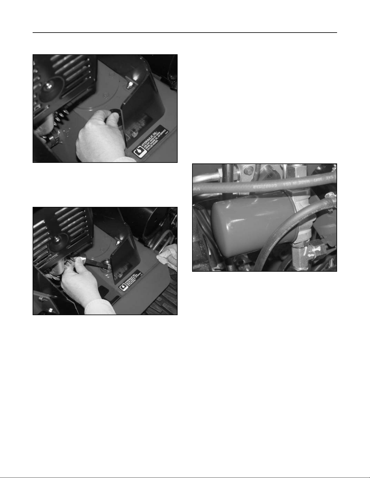
4. Clean the area around the filler neck of the
hydraulic tank (Fig. 009).
3-4
Rev. 000
Figure 009 DSC-0771
TX 413 Service Manual
Page 26
MAINTENANCE
5. Remove the cap from the filler neck (Fig. 010).
Figure 010 DSC-1368
6. Check the fluid level on the dipstick (Fig. 011).
Replacing the Hydraulic Filter
Change the hydraulic filter:
After the first 8 operating hours.
After every 200 operating hours.
1. Position traction unit on level surface.
2. Lower the loader arm, stop the engine, and
remove the key.
3. Open the hood.
IMPORTANT: Do not substitute an automotive
oil filter or severe hydraulic system damage may
result.
4. Remove the old filter (Fig. 012).
Figure 011 DSC-1369
5. The fluid level should be between the marks on
the dipstick. If the level is low, add enough fluid to
raise it to the proper level.
8. Install the cap on the filler neck.
Figure 012 DSC-1370
5. Wipe the surface of the filter adapter gasket area
clean.
6. Apply a thin coat of hydraulic fluid to the rubber
gasket on the replacement filter.
7. Install the replacement hydraulic filter onto the
filter adapter. Hand tighten it clockwise until the
rubber gasket contacts the filter adapter, then
tighten the filter an additional 3/4 turn.
8. Wipe up any spilled fluid.
TX 413 Service Manual
Rev. 000
3-5
Page 27
MAINTENANCE
9. Start the engine, raise and lower the loader arm,
then drive the unit forward and backward to
purge air from the system and check for leaks.
10. Stop the engine, check the fluid level in the
hydraulic tank (refer to Checking the Hydraulic
Fluid, page xx ) and add fluid to raise the level to
mark on dipstick. Do not over fill the tank.
11. Close the hood.
Note: Dispose of used oil and filters at a certified
recycling center.
Changing the Hydraulic Fluid
Change the hydraulic fluid every 400 operating hours
or yearly.
Note: The hydraulic filter should be replaced
whenever the hydraulic oil is changed.
1. Position the traction unit on a level surface.
2. Raise the loader arm, install the cylinder lock,
stop the engine, and remove the key.
6. Remove the hydraulic tank cap and dipstick
(Figures 014 and 015).
A
B
Figure 014 DSC-0771
A. Hydraulic Tank Cap B. Dipstick
3. Open the hood.
4. Allow the traction unit to cool completely.
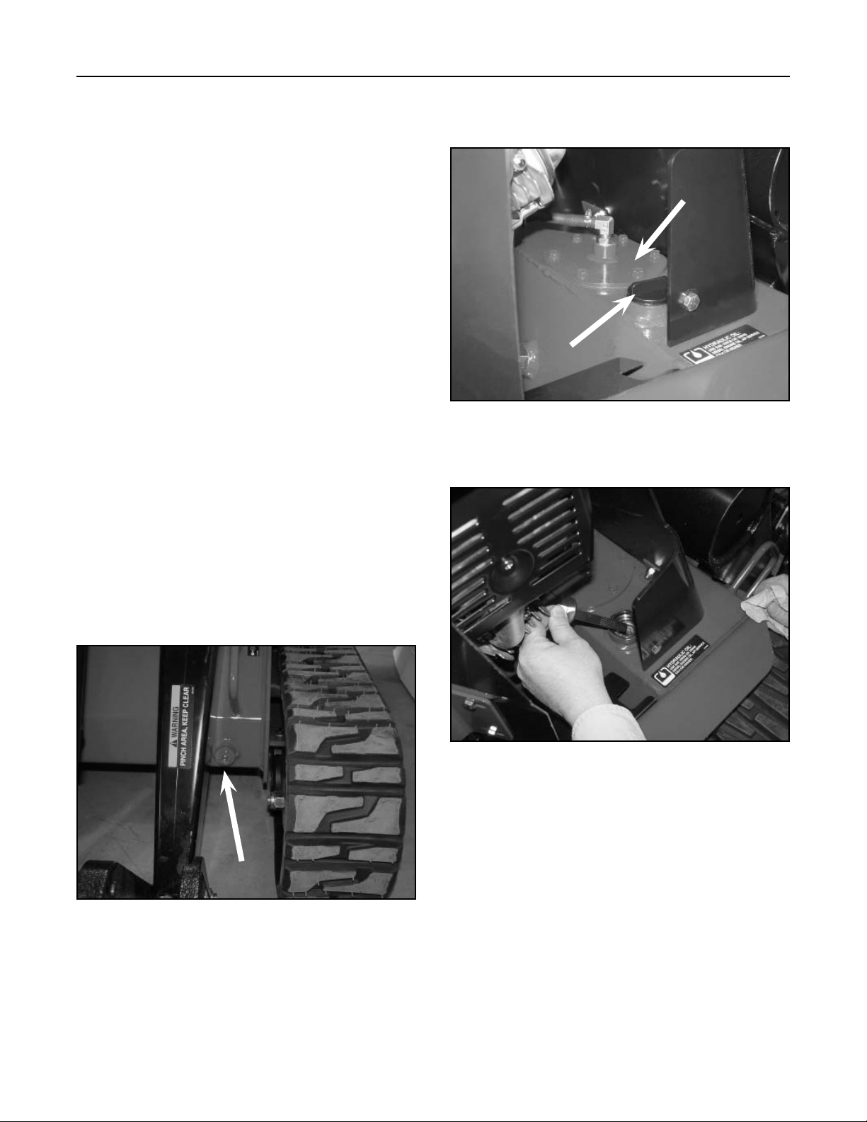
5. Place a large drain pan (capable of holding a
minimum of 10 gallons) under the drain plug on
the front of the traction unit (Fig. 013).
Figure 013 DSC-0772
Figure 015 DSC-1369
7. Remove the drain plug and allow the oil to drain
into the pan.
8. When oil is finished draining, install and tighten
the drain plug.
Note: Dispose of the used oil at a certified
recycling center.
3-6
9. Fill the hydraulic tank with approximately 10
Rev. 000
gallons (37.85 l) of 10w-30 or 15W-40 detergent,
diesel engine oil (API service CH-4 or higher).
TX 413 Service Manual
Page 28
MAINTENANCE
A
B
C
D
10. Replace the hydraulic oil filter.
11. Start the engine, remove the cylinder lock, raise
and lower the loader arm, then drive the unit forward and backward to purge air from the system
and check for leaks.
12. Stop the engine.
13. Check the hydraulic fluid level and top it off if
necessary.
Checking the Hydraulic Lines
After every 100 operating hours, check the hydraulic
lines and hoses for leaks, loose fittings, kinked lines,
loose mounting supports, wear, weather, and chemical deterioration. Replace all moving hydraulic hoses
every 1500 hours or 2 years, whichever comes first.
Make necessary repairs before operating.
Vents - Fuel Tank and Hydraulic Tank
Servicing the Engine, Air Cleaner
Replacement, and Spark Plug Servicing
See the Dingo TX 413 Operator's Manual. Or, for
more details, see the Honda Engine Operator’s or
Service Manuals.
Fuse Block
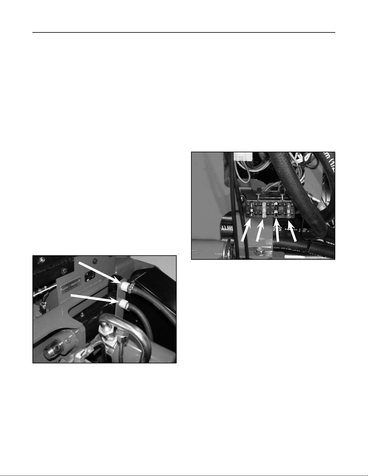
The fuse block is located inside the rear cover. There
are three fuses in the electrical system. One location
for the fuse is blank, for optional head lights (Fig.
017).
There are two vents located on the top of the unit.
The top one is the fuel tank vent, A, and the bottom
vent is for the hydraulic reservoir tank, B, (Fig. 016).
A
B
Figure 016 DSC-0773
Note: The only maintenance to perform on these
is to make sure they are clean and free of
any debris.
D
B
A
Figure 017 DSC-0753A
Fuses can be removed to check continuity. The test
meter should read less than 1 ohm.
A. 30 amp - Main/Starter, Blade Type
B. 25 amp - Charging, Blade Type
C. Blank - Optional Headlights, 10 amp
D. 10 amp - Ignition Circuit, Blade Type
C
TX 413 Service Manual
Rev. 000
3-7
Page 29

MAINTENANCE
Recommended Maintenance Schedule
Maintenance Service Interval
Maintenance Procedure
8 hrs
Grease the traction unit
Check engine oil level
Check for loose fasteners
Inspect the tracks for damage or wear
Change hydraulic filter after the initial 8-10
operating hours
25 hrs
Check hydraulic oil
Inspect hydraulic lines for leaks
50 hrs
Clean the foam pre-filter with liquid soap and warm
water
Clean the paper air filter by lightly tapping on flat
surface
100 hrs
Change engine oil
Replace paper air filter
Check battery electrolyte level
Adjust track tension
Check battery cable connections
Check the spark plug
200 hrs
Check hydraulic filter
300 hrs
Replace the spark plug
400 hrs
Inspect fuel lines for leaks
Change hydraulic oil and filter
Yearly Storage
Check for loose fasteners
Touch up chipped paint
Adjust track tension
Check tracks and road wheels
Complete all yearly maintenance procedures
specified in the engine operator’s manual
Charge the battery and disconnect the cables
(storage only)
Drain the gasoline (storage only)
3-8
Rev. 000
TX 413 Service Manual
Page 30
ENGINE
TX 413 Service Manual
Rev. 000
4-1
Page 31

ENGINE
Introduction
The engine removal and installation procedure
is provided in this manual. Refer to the engine
manufacturer's owner's and service manuals for
maintenance intervals and service procedures.
Engine Removal
1. Start the unit and raise the loader arm assembly
to the fully raised position. Install the cylinder lock
in the lift cylinder (Fig 018).
4. Remove the drive belt; refer to Drive Belt
Removal and Replacement, page 8-2.
5. Loosen the two set screws on the engine drive
pulley (Fig. 019).
Figure 019 DSC-1088
Figure 018 DSC-1041
2. Remove the belt cover and rear cover.
3. Disconnect the negative battery cable, then the
positive cable. Remove the battery from the unit.
6. Remove engine drive pulley after retracting the
idler pulley assembly (Fig. 020).
Figure 020 DSC-1089
4-2
Rev. 000
TX 413 Service Manual
Page 32

ENGINE
7. Remove the bolt and nut securing the exhaust
deflector to the left hand frame (Fig. 021).
Figure 021 DSC-1090
8. Remove the two bolts and nuts on the backside
of the exhaust deflector (Fig. 022).
9. Remove the four bolts and nuts at the base of the
front grille (Fig. 023).
Figure 023 DSC-1092
10. Remove the front grille with the exhaust deflector
attached (Fig. 024).
Figure 022 DSC-1091 Figure 024 DSC-1093
TX 413 Service Manual
Rev. 000
4-3
Page 33

ENGINE
11. Remove the gas tank vent hose on the hydraulic
oil filter bracket (Fig. 025).
Figure 025 DSC-1095
12. At the base of the fuel tank bracket, left side,
remove the two bolts and nuts holding the
bracket to the frame (Fig. 026).
13. Remove the bolt and nut retaining the hose
clamp for the oil reservoir vent hose and the
clamp holding the fuel shut off valve (Fig. 027).
Figure 027 DSC-1098
NOTE: If there is fuel in the gas tank and the fuel
line is removed between the gas tank and
the fuel shut off valve, fuel spillage will
occur. Drain fuel from the tank prior to
removing any fuel lines.
Figure 026 DSC-1096
14. Drain the fuel tank (Fig. 028).
Figure 028 DSC-1134
4-4
Rev. 000
TX 413 Service Manual
Page 34

ENGINE
A
B
C
D
15. Remove the fuel line clamp located at the electric
fuel shut off valve (fuel line between shut off valve
and carburetor (Fig. 029).
Figure 029 DSC-1099
16. Disconnect the wire terminals for the fuel shut off
valve (Fig. 030).
17. Remove the two bolts and nuts to the tank
bracket on the right side (Fig. 031).
Figure 031 DSC-1101
18. Remove the fuel tank and tank bracket (Fig. 032).
B
A
D
C
Figure 030 DSC-1100
A - Violet wire C - Green wire
B - Pink wire D - Yellow wire
Figure 032 DSC-1102
TX 413 Service Manual
Rev. 000
4-5
Page 35

ENGINE
A
B
19. Disconnect the charge coil wire, black to white
(Fig. 033).
Figure 033 DSC-1103
20. Disconnect the plug and jack connection for the
charge coil leads to the rectifier (Fig. 034).
21. Disconnect the oil switch, black to white wire (Fig.
035).
Figure 035 DSC-1107
22. Disconnect the blue wire and two red wires on
the starter assembly (Fig. 036).
Figure 034 DSC-1105
B
A
Figure 036 DSC-1111
A - Blue wire B - Red wires
4-6
Rev. 000
TX 413 Service Manual
Page 36

ENGINE
A
B
A
B
23. Disconnect the throttle cable clamp and the throttle cable from the top of the engine (Fig. 037).
B
A
Figure 037 DSC-1112
A. Throttle Clamp B. Throttle Cable
24. Remove the engine air cleaner cover. Disconnect
the choke cable clamp and choke cable from the
front of the engine (Fig. 038).
25. Remove the two front engine mounting bolts and
nuts (Fig. 039).
Figure 039 DSC-1114
26. Remove the two rear engine mounting bolts and
nuts.
Note: The left rear bolt and nut has two ground
wires; a star washer is located between the
ring terminals of the wires and the engine
block (Fig. 040).
B
A
Figure 038 DSC-1113
A. Choke Cable Clamp B. Choke Cable
TX 413 Service Manual
Rev. 000
Figure 040 DSC-1115
4-7
Page 37

ENGINE
27. With an overhead hoist, raise the engine slightly
and slide the engine forward and then up and off
the frame of the unit (Fig. 041).
Figure 041 DSC-1118
Engine Installation
2. Install the two rear engine mounting bolts and
nuts.
Note: Make sure the two ground wires are
installed on the left rear bolt, with the star
washer installed first. DO NOT TIGHTEN
THE BOLTS AND NUTS. (Fig. 043)
Figure 043 DSC-1115
1. Lower engine to the frame (Fig. 042).
Figure 042 DSC-1118
3. Install the two front engine mounting bolts and
nuts.
Note: DO NOT TIGHTEN THE BOLTS AND NUTS
(Fig. 044).
Figure 044 DSC-1120
4-8
Rev. 000
TX 413 Service Manual
Page 38

ENGINE
9. Apply an anti-seize compound to the engine
crankshaft and key. Apply a medium strength
threadlocking material to the threads of the set
screws and install the engine drive pulley. Using
a straight edge, align the engine drive pulley
to the lower hydrostatic pump pulley; with the
engine bolts loose, you can move the engine to
help align the pulley (Fig. 045).
Note: The belt idler pulley will need to be
retracted while aligning the engine pulley
with the hydrostatic pump pulley.
Choke Cable Installation
1. Move the choke control on the dash to full
position, then back the choke control so it is
approximately 1/16" (1.6mm) away from the front
edge of the slot (Fig. 047).
Figure 047 DSC-1123
Figure 045 DSC-1119
10. Tighten all four engine mounting bolts and nuts
and torque to 18 ft-lbs. (24.4 Nm) (Fig. 046).
Figure 046 DSC-1114
11. Recheck the alignment of the engine drive pulley,
then tighten the set screws on the engine drive
pulley.
2. At the carburetor linkage, insert the cable through
the cable clamp and into the hole in the choke
lever. Pull the choke lever to the full choke
position and hold; tighten the screw on the choke
lever (Fig. 048).
Figure 048 DSC-1124
3. While holding the choke lever, tighten the
screw/clamp for the cable. Test for proper choke
operation. Install the engine air cleaner cover.
TX 413 Service Manual
Rev. 000
4-9
Page 39

ENGINE
A
B
Throttle Cable Installation
1. Move the throttle control on the dash to full position, then back the throttle control so it is approximately 1/16" (1.6mm) away from the front edge
of the slot (Fig. 049).
Figure 049 DSC-1126
4. Connect the blue wire onto the spade terminal
and the two red wires to the post on the starter
assembly (Fig. 051).
B
A
Figure 051 DSC-1111
A - Blue wire B - Red wires
2. On the engine, insert the cable under the clamp;
move the engine throttle lever to the full open
position and hold; tighten the screw on the
throttle lever (Fig. 050).
Figure 050 DSC-1127
3. While holding the throttle lever, tighten the
screw/clamp for the cable. Test for proper throttle
control operation.
5. Connect the oil switch, black to white wire (Fig.
052).
Figure 052 DSC-1107
4-10
Rev. 000
TX 413 Service Manual
Page 40

ENGINE
6. Connect the plug and jack connection to the
alternator wires to the rectifier (Fig. 053).
Figure 053 DSC-1105
7. Connect the magneto wire, black to white wire
(Fig. 054).
8. Install the fuel tank and tank bracket on the frame
(Fig. 055).
Figure 055 DSC-1102
9. Install two bolts and nuts located on the right side
of the tank bracket and leave loose (Fig. 056).
Figure 054 DSC-1103
TX 413 Service Manual
Rev. 000
Figure 056 DSC-1128
4-11
Page 41

ENGINE
A
B
C
D
10. Connect the wire terminals for the fuel shut off
valve (Fig. 057).
D
C
B
A
Figure 057 DSC-1100
A - Green wire C - Violet wire
B - Yellow wire D - Pink wire
11. Connect fuel line and install the fuel line clamp
located at the fuel shut off valve (Fig. 058).
12. Install the bolt and nut retaining the hose clamp
for the oil reservoir vent hose and the clamp
holding the fuel shut off valve and tighten (Fig.
059).
Figure 059 DSC-1098
13. Install the two bolts and nuts, left side, holding
the fuel tank bracket to the frame and tighten
(Fig. 060).
Figure 058 DSC-1099
4-12
14. Tighten the right side fuel tank bracket nuts and
Rev. 000
Figure 060 DSC-1096
bolts.
TX 413 Service Manual
Page 42

ENGINE
15. Install the fuel tank vent hose on the oil filter
bracket (Fig. 061).
Figure 061 DSC-1095
16. Install the front grille with the exhaust deflector
attached (Fig. 062).
17. Install four bolts and washers located at the base
of the front grille (Fig. 063).
Figure 063 DSC-1129
18. Install the two bolts and nuts on the backside of
the exhaust deflector (Fig. 064).
Figure 062 DSC-1093
TX 413 Service Manual
Rev. 000
Figure 064 DSC-1091
4-13
Page 43

ENGINE
19. Install bolt and nut located at the bottom of the
exhaust deflector and tighten the bolt (Fig. 065).
Then tighten the rest of the bolts in the front
grille, the right side tank bracket, and on the
exhaust deflector.
Figure 065 DSC-1090
Fuel Tank Removal
1. Start the unit, raise the lift arm to the fully raised
position and install the hydraulic cylinder lock in
the lift cylinder. Shut engine off.
2. Remove the rear cover and remove the negative
battery cable.
3. Remove the fuel tank vent hose from the oil filter
bracket (Fig. 066).
20. Install the drive belt; refer to Drive Belt Removal
and Installation, pages 8-2 and 8-3.
21. Install the battery. Connect the positive cable,
then the negative cable.
22. Install the belt cover and rear cover.
23. Remove the hydraulic cylinder lock in the lift
cylinder.
24. Start the unit and lower the lift arm. Check the
engine high engine RPM. The engine RPM
should be at 3600 + 150 RPM.
Figure 066 DSC-1095
4. Remove the two bolts and nuts retaining the tank
straps located at the top of the fuel tank (Fig.
067).
Figure 067 DSC-1131
4-14
Rev. 000
TX 413 Service Manual
Page 44

ENGINE
5. Disconnect the fuel line located on fuel shut off
valve that goes to the fuel tank (Fig. 068).
Figure 068 DSC-1133
6. Drain the fuel tank (Fig. 069).
7. Remove the fuel line from the fuel tank fitting.
With a wrench, turn the fuel tank fitting so it is
pointing out toward the left side of the unit (Fig.
070).
Figure 070 DSC-1137
8. Remove the fuel tank from the unit (Fig. 071).
Figure 069 DSC-1134
TX 413 Service Manual
Rev. 000
Figure 071 DSC-1139
4-15
Page 45

ENGINE
Bulkhead Fuel Fitting Replacement
1. Remove the nut and washer from the fuel fitting
(Fig. 072).
Figure 072 DSC-1140
2. Tape a piece of steel wire approximately 30" long
to the fitting , then push the fitting into the tank,
tilt the tank and feed the fuel fitting out the fill
neck of the fuel tank (Fig. 073).
3. Remove the fuel fitting from the steel wire. Tape a
new fuel fitting to the steel wire and pull the fitting
through the fuel tank and out the bottom of the
tank (Fig. 074).
Figure 074 DSC-1142
4. Remove the wire and install the washer and nut
on the fitting, then finger tighten the nut. Orient
the fitting as shown (Fig. 075).
Figure 073 DSC-1141
4-16
Rev. 000
Figure 075 DSC-1143
TX 413 Service Manual
Page 46

ENGINE
Fuel Tank Installation
1. Install the fuel tank on the unit taking care not to
damage the fuel fitting (Fig. 076).
Figure 076 DSC-1139
2. Turn the fuel fitting toward the rear of the unit and
tighten the fitting nut, then install the fuel line and
clamp (Fig. 077).
3. Install the fuel line on the fuel shut off valve and
install the clamp (Fig. 078).
Figure 078 DSC-1133
4. Install the two fuel tank straps located on the top
of the fuel tank and install the nuts and bolts and
tighten (Fig. 079).
Figure 077 DSC-1137
TX 413 Service Manual
Rev. 000
Figure 079 DSC-1131
4-17
Page 47

ENGINE
5. Install the vent hose on the oil filter bracket (Fig.
080).
Figure 080 DSC-1095
6. Install the positive battery cable, then the
negative cable.
7. Install the rear cover.
8. Start the unit and check for any fuel leaks.
Remove the hydraulic cylinder lock on the lift
cylinder and lower the lift arm.
Starter Service
Serial numbers 200000200 and higher have an
opening for easier access to the starter (Fig. 081).
Figure 081 DSC-0583
Manual Shutoff
This engine also has the manual fuel shut off on the
carburetor (Fig. 082).
4-18
Rev. 000
Figure 082 manual shutoff
TX 413 Service Manual
Page 48

ELECTRICAL SYSTEM
PK PK BN GN
R
VIO
_
NEUTRAL
CLOSED WHEN
IN NEUTRAL
FUEL SOLENOID
K1
KILL RELAY
F4
10 A
PK
SW2
GN
DETENT
CLOSED WHEN
OUT OF DETENT
BN
Y
4
5
<
<
<
2
BK
BK
+
HOUR METER
F2
VIO
25 A
GN
GN
2
K2
1
<
START
<
<
RELAY
3
5
4
T BU
SW5
W
3
1
R
F1
30 A
R
R
BK
SPARK
GY
PLUG
GY
W
BU
W
NOTE: SOME WIRE COLORS CHANGE
AT REGULATOR CONNECTOR
BK
GND
W
REG. DC
BK/Y
B+
VOLTAGE
REGULATOR
GY
AC
GY
AC
W/BU
CHARGE LAMP
IGNITION
MODULE
AC
AC
MAGNETO
+
B
ST
STARTER
OIL SWITCH
CLOSES WHEN
OIL IS LOW
_
TX 413 Service Manual
Rev. 000
5-1
Page 49

ELECTRICAL SYSTEM
A
B
There are two primary current paths when the
ignition switch is in the "START" position. (1) Current
flows from the ignition switch to both the coil and
contact terminals of the start relay. From the coil
terminal of the start relay, current flows to the neutral
detent (located on the Auxiliary Power Valve) to the
contact terminal of the kill relay. Also, current flows to
the engine starter. (2) At the same time, current flows
to a neutral switch, (located on the control handle
assembly) and to the engine fuel solenoid. From the
neutral switch current flows to the coil terminal of the
kill relay, which activates and takes the electronic
ignition wire off of ground to allow the engine to have
spark.
The following electrical section covers most of the
electrical components used on the TX 413. It covers
each electrical component's purpose, how it works,
testing procedures and location on the unit.
Relay
Purpose
The TX 413 uses two relays to direct current flow
to different areas of the unit. The two relays are the
kill relay and the start relay. Electrically, they both
operate the same.
How It Works
A relay is an electrically actuated switch.
1. Coil: Terminals 85 and 86 are connected to a
coil. Applying 12 volts to these terminals energizes the coil turning it into an electromagnet.
2. Switch: Terminals 30, 87 and 87a are actually
part of a single pole, double throw (SPDT) switch.
Terminal 30 is the common lead. The switch is
spring loaded so that 30 and 87a are connect
when the coil is not energized. When the coil is
energized, the switch is "thrown" and 30 and 87
are connected (Fig. 084).
Location
The relays are located behind the rear cover, in
back of the hoses (Fig. 083).
B
A
Figure 083 DSC-0753
A. Start relay B. Kill relay
Figure 084 MVC-0671X
Testing
1. Disconnect the relay from the harness.
2. Verify the coil resistance between terminals
85 and 86 with a multimeter (ohms setting).
Resistance should be from 70 to 90 ohms. There
should be continuity between terminals 87a and
30 (Fig. 108).
3. Connect the multimeter (ohms setting) leads to
relay terminals 30 and 87. Ground terminal 86
and apply +12 VDC to terminal 85. The relay
should make and break continuity terminals 30
and 87 as 12 VDC is applied and removed from
terminal 85 (Fig. 108).
5-2
Rev. 000
TX 413 Service Manual
Page 50

ELECTRICAL SYSTEM
4. Connect multimeter (ohms setting) leads to
relay terminals 30 and 87a. Apply +12 VDC to
terminal 85. With terminal 86 still grounded, the
relay should break and make continuity between
terminals 30 and 87a as 12 VDC is applied and
removed from the terminal (Fig. 085).
Figure 085 xl relay
5. Disconnect voltage and multimeter leads from
relay terminals.
Location
The ignition switch is located on the top control
panel (Fig. 087).
Figure 087 DSC-0750
How It Works
Detents inside the switch give it 3 positions: OFF,
RUN, and START. The START position is spring loaded so the cylinder automatically returns to RUN once
the key is released.
Ignition Switch
Purpose
This component provides the proper switching for
the starter, ignition, accessories, and safety circuits
(Fig. 086).
Figure 086 mvc-166 art
Testing
1. Disconnect the switch from the wiring harness.
2. Verify that continuity exists between the terminals
listed for the switch position. Verify that there is NO
continuity between terminals not listed for the switch
position (Figure 086).
Position Condition
Off No continuity
Start B + I + S
Run B + I + A and X + Y
TX 413 Service Manual
Rev. 000
5-3
Page 51

ELECTRICAL SYSTEM
Auxiliary Power Neutral Switch
Purpose
3. The normally closed ball type switch is used on
the auxiliary power valve. This is a safety type switch
to make sure the auxiliary power valve is in the
neutral detent (Fig. 088).
Figure 088 MVC-0866X
Testing
1. Disconnect the switch from the wiring harness.
Leave the switch in the Auxiliary Power Valve.
2. Using a VOM multimeter (ohms setting) there
should be continuity between the two wire
terminals.
3. Leave the Multimeter (ohms setting) leads
connected to the two wire terminals. Move the
auxiliary power valve handle to either the reverse
flow or forward flow position. There should be NO
continuity.
Regulator-Rectifier
Purpose
The regulator-rectifier changes AC stator to
DC and regulates the charging current, to prevent
overcharging the battery (Fig. 090).
Location
The auxiliary power neutral switch is located
behind the rear cover, on the left side of the unit, on
the auxiliary power valve (Fig. 089).
Figure 089 DSC-0758
Figure 090 MVC-0870X
5-4
Rev. 000
TX 413 Service Manual
Page 52

ELECTRICAL SYSTEM
Location
The regulator-rectifier is located behind the rear
cover, in back of the hoses (Fig. 091).
Figure 091 DSC-0753
How It Works
This regulator-rectifier, like many others, must
be connected to the battery to function. Once the
voltage level of the battery exceeds approximately
14 volts, the regulator-rectifier stops sending current
to the battery and no charging takes place. When
the voltage again drops below the specified level,
the regulator-rectifier sends the current back to the
battery.
3. If not, check stator output. Using a multimeter
set to AC volts, connect a probe to D and E
terminal (grey wire). Start the unit and operate at
full throttle. The AC voltage should be 27 volts or
more. If not, the stator is bad. Stator resistance
can also be checked - it should be 0.16 - 0.24
Ohms. If OK, proceed to step 4.
4. Shut the engine OFF. Disconnect the electrical
connector from the regulator-rectifier. Set
the multimeter to read Ohms. The resistance
measurements are:
D and A, C, E infinity
E and A, C infinity
A and D, E 1 - 200 KΩ
A and C 0.1 - 100 KΩ
C and D, E 0.1 - 50 KΩ
(Fig. 092).
A
B
C
Testing
1. Check the battery before checking the voltage
regulator. The battery must be fully charged
and in good condition for the voltage regulator
to operate properly. (The voltage across the the
battery terminals should be 13.6 volts or more.)
2. Using a multimeter set to DC volts, insert the
positive probe of the meter into either A or B
terminal violet wire. The negative probe should
go to ground (C) or to the negative battery cable.
Check the reading on the meter. Start the unit
and operate the engine at full throttle. You should
see an increase in DC voltage and should read
13.6 to 14 DC voltage or more. System is OK.
TX 413 Service Manual
Rev. 000
D
Figure 092 MVC-0872X
A. Violet Wire (B+ to fuse 25A)
B. Violet Wire (B+ to fuse 25A)
C. Black Wire (Ground)
D. Grey Wire (AC from Charge Coil Engine)
E. Grey Wire (AC from Charge Coil Engine)
E
5-5
Page 53

ELECTRICAL SYSTEM
Hour Meter
Purpose
The hour meter keeps track of how long the
key has been in the "RUN" position. Also, the hour
meter has a Maintenance Reminder Program. Icons
will flash 3 hours before the service interval through
3 hours after the service interval. The service icon
(looks like an hourglass) is set-up to flash at 8 hours
(Break-in Period) and then every 99 hours.
At every 399 hour interval a second icon will
flash. The "SVC" icon is a reminder to change the
hydraulic oil and filter.
Location
The hour meter is located under the hood, toward
the dash assembly (Fig. 093).
Testing
1. Verify that 12 volts is present across the two
terminals when the key is in the "RUN" position.
Since the meter is polarized, it is important the
positive wire is connected to the correct terminal (Fig.
118).
2. When the meter is operating properly, the
hourglass icon will be flashing on and off. If the
hourglass icon is not showing and the meter is
hooked up properly, replace the meter (Fig. 094).
A
B
Figure 093 DSC-0755
How It Works
The hour meter is an electronic digital clock.
It has its own internal battery to keep memory of
the hours, when the engine is not running. It is not
repairable or resettable.
Figure 094 MVC-0877X
Neutral Proximity Switch
Purpose
Used to ensure the traction control lever is in the
neutral/stop position when starting the unit. It is a
magnetic type switch and it must be in proximity with
the traction control lever bolt to close the contacts
(Fig. 095).
Figure 095 MVC-0878X
5-6
Rev. 000
TX 413 Service Manual
Page 54

ELECTRICAL SYSTEM
Location
The neutral proximity switch is located behind
the rear cover, under the dash, in front of the traction
control lever (Fig. 096), and can be viewed and
adjusted from under the hood.
Figure 096 DSC-0756
Testing
1. Before electrically testing the switch, check the
location of the switch and bolt, to make sure they are
meeting in the sense zone on the switch. Both the
switch and the bolt are adjustable and the air gap
between them should be 1/8” to 1/4" (3.2 to 6.4mm).
2. Disconnect the switch from the wiring harness
and remove from the unit.
3. Using a multimeter (ohms setting), check the
continuity of the switch at the wire terminals. There
should be NO continuity (switch open).
4. Using the steel blade of a screw driver or similar,
touch the blade of the screw driver up against the
sense zone of the switch and check the continuity,
there should be continuity (switch closed) (Fig. 098).
How It Works
The neutral proximity switch has a sense zone
which is the magnetic portion on the switch (Fig.
097). A bolt located on the traction control lever aligns
with the sense zone in the neutral/stop position to
magnetically close the contacts in the switch.
Figure 097 MVC-0885X
Figure 098 MVC-0879X
TX 413 Service Manual
Rev. 000
5-7
Page 55

ELECTRICAL SYSTEM
Fuel Solenoid or Shutoff Valve
Purpose
The fuel shutoff valve is located in-line between
the gas tank and the engine carburetor. When the
ignition switch is in the "OFF" position, fuel will not
flow to the engine carburetor. When the ignition
switch is in the "START" and "RUN" positions, the
shutoff valve is open.
Location
The fuel shutoff valve is located on the left side of
the unit, next to the engine (Fig. 099).
Testing
1. With the fuel solenoid connected to the wire
harness, turn the ignition key to the "RUN" position.
Verify there is 12 VDC at the connector with the pink
wire.
2. If 12 VDC is present, carefully disconnect the
fuel line from the fuel shutoff valve. You will need a
container handy to catch any fuel. Turn the ignition
key to the "RUN" position. Fuel should flow out of the
fuel shutoff valve. If not, replace the valve (Fig. 100).
Figure 099 DSC-0762
How It Works
The fuel solenoid/shutoff valve is an electrically
actuated valve. When 12 VDC is supplied to the
valve, the valve opens and fuel will flow to the
carburetor.
Figure 100 DSC-1729
5-8
Rev. 000
TX 413 Service Manual
Page 56

Electrical Schematic Wiring Diagram
ELECTRICAL SYSTEM
X I Y S B A
PK PK BN GN
SW2
NEUTRAL
CLOSED WHEN
IN NEUTRAL
FUEL SOLENOID
CLOSED WHEN
OUT OF DETENT
K1
KILL RELAY
PN 88-9830
X
I
OFF = no connections
S
Y
A
IGNITION SWITCH
PK
GN
DETENT
BN
5
<
<
<
2
BK
ON
START
B
Ignition switch terminal
Locations viewed from back
SW4
F4
10 A
GN
2
<
<
<
5
T BU
SW5
Y
W
4
3
1
BK
= B I A and X Y
= B I S
R
VIO
GN
K2
1
START
RELAY
3
4
HOUR METER
F2
25 A
R
F1
30 A
R
WIRE COLOR CODES
BK – BLACK PK – PINK
BN – BROWN R – RED
BU – BLUE T – TAN
GN – GREEN VIO – VIOLET
GY – GREY W – WHITE
OR – ORANGE Y – YELLOW
BK/Y – BLACK/YELLOW W/BU – WHITE/BLUE
F3
10A
_
+
BK
VIO
GY
SPARK
PLUG
GY
W
R
BU
OPTIONAL HEADLIGHTS
VIO
BK
NOTE: SOME WIRE COLORS CHANGE
AT REGULATOR CONNECTOR
BK
GND
W
REG. DC
BK/Y
B+
VOLTAGE
AC
AC
CHARGE LAMP
+
B
ST
REGULATOR
_
GY
GY
W/BU
IGNITION
MODULE
AC
AC
MAGNETO
STARTER
B
A
TX 413 Service Manual
GND
Rev. 000
W
OIL SWITCH
CLOSES WHEN
OIL IS LOW
BK
5-9
Page 57

ELECTRICAL SYSTEM
THIS PAGE INTENTIONALLY LEFT BLANK.
5-10
5-10
Rev. 000
TX 413 Service Manual
TX 413 Service Manual
Page 58

HYDRAULIC SYSTEM
TX 413 Service Manual
Rev. 000
6-1
Page 59

HYDRAULIC SYSTEM
Hydrostatic Pump Reference Drawing
5
Hydrostatic Pump
(Left Drive)
7
4A
1
4A
4B
1. Hydraulic Return Line to
Reservoir Tank
6
2. Hydrostatic Pumps Case Drain
Line to Reservoir Tank
3A. Right Drive Hydraulic Line
3B. Right Drive Hydraulic Line
4A. Left Drive Hydraulic Line
4B. Left Drive Hydraulic Line
5. Case Drain Hydraulic Line
6. Inlet Hydraulic Line (lower pump)
7. Inlet Hydraulic Line (upper pump)
4B
Hydrostatic Pump
(Right Drive)
3B
3A
6
1
5
2
4B
4A
2
1
6-2
Wheel Motor
(Right Drive)
Rev. 000
Wheel Motor
(Left Drive)
TX 413 Service Manual
Page 60

Line “I”
HYDRAULIC SYSTEM
Valve Reference Drawings
Line “2”
Line “H”
Loader Arm Hydraulic Lines
Line “E”
Line “3”
Principal Hydraulic Lines
Line “A”
Line “B”
Line “C”
Line “D”
Line “4”
TX 413 Service Manual
Rev. 000
Line “1”
6-3
Page 61

HYDRAULIC SYSTEM
Purging Air Procedures
Due to the effects air has on efficiency in hydrostatic
drive applications, it is critical that air is purged from
the system.
These purge procedures should be implemented
anytime a hydrostatic system or hydraulic lines
has been opened to facilitate maintenance or any
additional oil has been added to the system.
Air creates inefficiency because it has compression
and expansion rates that are higher than that of oil.
Trapped air in the oil may cause the following
symptoms:
1. Noisy operation.
2. Lack of power or drive after short-term operation.
3. High oil temperature and excessive expansion of
oil.
Before starting, make sure the reservoir is at
the proper oil level. If it is not, fill to the vehicle
specifications, refer to the Hydraulic Reservoir Tank,
Checking the Hydraulic Fluid section on page 3-4.
The following procedures should be performed with
the vehicle drive tracks off the ground, then repeated
under normal operating conditions.
1. Lift/support the unit so that both tracks are off the
ground and free to rotate.
Adjusting the Tracking of the Traction
Control, Full Forward Position
If the traction unit does not drive straight when you
hold the traction control against the reference bar,
complete the following procedure:
Note: Whenever an adjustment is made, check to
make sure the set screws contact stops in
the full forward motion.
1. Drive the traction unit with the traction control
against the reference bar, noting which direction
the traction unit veers.
2. Release the traction control.
Note: When the traction control is stroked fully
forward and the unit has severe pull to
the left or right, a problem with the pump
control linkage or a hydraulic component is
indicated.
Note: When the traction control is stroked fully
and a gradual pull happens, the tracking
adjustment can be made. A very slight
tracking error is considered normal.
3. If the traction unit veers left, loosen the right jam
nut and adjust the tracking set screw on the rear
of traction control (Fig. 101).
2. Start the engine and run it at slow idle engine
speed for about 20 seconds.
3. Push the traction control to full forward position
and hold. The tracks should begin to slowly turn.
Once the tracks begin to turn smoothly, allow to
run for 20 seconds. Pull the traction control to
full reverse position and hold. Again, the tracks
should begin to slowly turn in reverse. Once the
tracks begin to turn smoothly, allow to run for 30
seconds.
4. Raise and lower the loader arm for 4 complete
cycles. Raise loader arm and put into the float
position, loader arm should drop.
5. Cycle the dump cylinder for 4 complete cycles.
6. Stop the engine and check the oil level in the
reservoir and add if necessary.
7. It may be necessary to repeat Steps 2 through
6, until all the air is completely purged from the
system.
C
B
A
Figure 101 fig 38.bmp
A. Right jam nut B. Operator Handle
C. Reference Bar
6-4
Rev. 000
TX 413 Service Manual
Page 62

HYDRAULIC SYSTEM
4. If the traction unit veers right, loosen the left jam
nut and adjust the tracking set screw on front of
the traction control (Fig. 102).
C
B
A
Figure 102 fig 38.bmp
A. Left jam nut B. Operator Handle
C. Reference Bar
4. Open the rear access cover (Fig. 103).
Figure 103 DSC-0778
Note: Slight creeping of tracks in the forward or
reverse drive with tracks off the ground
can be a normal condition.
5. Repeat steps 1 through 4 until the traction unit
drives straight in the full forward position.
Adjusting the Traction Control Neutral
Position
If the traction unit creeps forward or backward when
the traction control is in neutral (and the unit is fully
warmed up), immediately complete the following
procedure:
1. Park the traction unit on a flat surface and lower
the loader arm.
2. Stop the engine and remove the key.
3. Lift/support the traction unit so that both tracks
are off of the ground.
5. Loosen the jam nuts on the traction rods, under
the control panel (Fig. 104).
A
B
Figure 104 fig. 37.bmp
A. Traction rods B. Jam nuts
TX 413 Service Manual
Rev. 000
6-5
Page 63

HYDRAULIC SYSTEM
6. Start the traction unit and set the engine throttle
to 1/3 engine throttle speed.
7. If the left track moves, lengthen or shorten the
right traction rod until the track stops moving.
8. If the right track moves, lengthen or shorten the
left traction rod until the track stops moving.
9. Tighten the jam nuts.
10. Close the rear access cover.
11. Stop the engine and lower the traction unit to the
ground.
12. Test for proper operation.
Hydrostatic Pump (Right Drive) Removal
Note: Cleanliness is a key factor in a successful
repair of any hydrostatic system.
Thoroughly clean all exposed surfaces
prior to any type of maintenance. Cleaning
all parts by using a solvent wash and air
drying is usually adequate. As with any
precision equipment, all parts must be kept
free of foreign material and chemicals.
Protect all exposed sealing areas and open
cavities from damage and foreign material.
4. Loosen the two set screws located on the
hydrostatic pump pulley and remove the pulley
(Fig. 105).
Figure 105 DSC-0859
5. With an offset open end wrench remove the inlet
hydraulic line, (page 6-2, Ref. 6), that runs to the
lower hydrostatic pump, (Fig. 106).
Upon removal, all seals, O-rings, and
gaskets should be replaced. During
installation, lightly lubricate all seals, Orings and gaskets with clean petroleum
jelly prior to assembly.
1. Lift/support the unit so the tracks are off the
ground.
2. Raise the hood and remove the belt cover.
Remove the rear cover and disconnect the
battery cables and remove the battery.
3. Remove drive belt, refer to the Drive Belt
Removal section of this manual page 8-2.
Figure 106 DSC-0860
6-6
Rev. 000
TX 413 Service Manual
Page 64

HYDRAULIC SYSTEM
6. Remove the upper end of the inlet hydraulic line
at the T-fitting adapter, (page 6-2, Ref. 6), located
on the lower hydrostatic pump (Fig. 107, top
view).
Figure 107 DSC-0861
7. On the lower side of the T-fitting adapter, remove
the hydraulic inlet line, (page 6-2, Ref. 7), from
the lower hydrostatic pump that runs to the upper
hydrostatic pump (Fig. 108, top view).
8. Loosen and remove the hydraulic inlet line, (page
6-2, ref 7), located on the back side of the upper
hydrostatic pump (Fig. 109).
Figure 109 DSC-0864
9. Disconnect the hydrostatic case drain line from
the T-fitting adapter, (page 6-2, Ref. 5), at the
lower hydrostatic pump (Fig. 110, rear view).
Figure 108 DSC-0863
TX 413 Service Manual
Rev. 000
Figure 110 DSC-0869
6-7
Page 65

HYDRAULIC SYSTEM
10. Disconnect the hydraulic case drain line,
(page 6-2, Ref. 2), from the bottom of the right
drive hydrostatic pump, at the T-fitting that is
connected to the reservoir tank (Fig. 111, rear
view).
Figure 111 DSC-0869a
12. Disconnect the two hydraulic lines to the wheel
motor, (page 6-2, Ref. 3A and 3B), (Fig. 113).
Note: It may be necessary to loosen the
hydraulic lines at the wheel motors.
Figure 113 DSC-0871
11. Disconnect the hydraulic case drain line from the
upper hydrostatic pump, (page 6-2, Ref. 5), and
remove the line (Fig. 112).
Figure 112 DSC-0870
13. Position the control handle so you can install
a 1/4" Allen wrench into the Allen head bolt
retaining the rod linkage to the pump lever
assembly, (Fig. 114).
Figure 114 DSC-0874
6-8
Rev. 000
TX 413 Service Manual
Page 66

HYDRAULIC SYSTEM
14. Remove the Allen bolt, spacer, and nut from the
pump lever assembly (Fig. 115).
Figure 115 DSC-0876
15. Remove the two bolts and nuts holding the
hydrostatic pump to the frame (Fig. 116).
16. Carefully lower the hydrostatic pump down and
maneuver under the hydraulic hoses and out of
the backside of the unit (Fig. 117).
Figure 117 DSC-0878
Hydrostatic Pump Service
Figure 116 DSC-0877
For hydrostatic pump service, refer to Hydro-Gear
BDP-10 service manual (Toro P/N 492-4789).
Hydrostatic Pump (Right Drive)
Installation
Note: As a reminder, prior to connecting the
hydraulic lines, the O-rings should be
replaced with new ones and lightly
lubricated with petroleum jelly.
1. When installing a new hydrostatic pump, make
sure all the hydraulic fittings are installed
properly; refer to the Hydrostatic Pump (Right
Drive) Fittings and Pump Lever Assembly on
pages 6-17.
TX 413 Service Manual
Rev. 000
6-9
Page 67

HYDRAULIC SYSTEM
A
A
2. Maneuver the right drive hydrostatic pump under
the hydraulic hoses and up to the opening in the
frame. Secure the frame with two bolts and nuts.
DO NOT tighten the bolts at this time (Fig. 118).
Figure 118 DSC-0884
3. Connect the two hydraulic lines that run to the
right wheel motor, (page 6-2, Ref. 3A and 3B),
and hand tighten (Fig. 119).
4. Connect and hand tighten the inlet hydraulic line
from the T-fitting adapter (page 6-2, Ref. 7) from
the right drive hydrostatic pump to the left drive
hydrostatic pump (Fig. 120, top view and Fig
121).
A
Figure 120 DSC-0885
A. Left Hand Drive Pump
Figure 119 DSC-0871
6-10
Rev. 000
A
B
Figure 121 DSC-0886
A. Left Hand Drive Pump
B. Inlet Hydraulic Line from T-fitting Adapter
TX 413 Service Manual
Page 68

HYDRAULIC SYSTEM
5. Connect and hand tighten the case drain
hydraulic line (page 6-2, Ref. 2) to the bottom of
the T-fitting adapter, located on the bottom of the
right drive hydrostatic pump (Fig. 122, rear view).
Figure 122 DSC-0887
6. Connect and hand tighten the case drain
hydraulic line (page 6-2, Ref. 5) from the T-fitting
located at the bottom of the right drive hydrostatic
pump to the top 90° fitting located on the top of
left drive hydrostatic pump (Fig. 123, rear view).
7. Connect and hand tighten the case drain
hydraulic line (page 6-2, Ref. 6), to the 90° fitting
located on the top of the left drive hydrostatic
pump (page 6-2, Ref. 1) (Fig. 124).
Figure 124 DSC-0903
8. Recheck all the fitting connections and tighten.
9. Tighten the two right drive hydrostatic pump
mounting bolts and torque to 50 + 5 ft-lbs. (70 + 7
Nm) (Fig. 125).
Figure 123 DSC-0869
TX 413 Service Manual
Rev. 000
Figure 125 DSC-0888
6-11
Page 69

A
B
C
D
HYDRAULIC SYSTEM
10. Position the control handle so the Allen head bolt
can be installed through the rod, linkage spacer,
pump lever assembly, and a nut. Tighten the
assembly and make sure the control handle is
moving freely (Fig. 126).
A
D
B
C
Figure 126 DSC-0876
A. Allen head bolt C. Pump lever assembly
B. Linkage spacer D. Nut
11. Apply anti-sieze compound on the right drive
hydrostatic pump shaft. Also, apply a medium
strength threadlocking material to the pulley set
screws. Install the hydrostatic pump pulley on the
shaft and key, making sure the set screws are
facing outward and the pulley is flush with the end
of the pump shaft (Fig. 127). Then tighten the set
screws to 215 + 35 in-lbs. (24 + 4 Nm).
12. Install drive belt; refer to the Drive Belt Installation
section on page 8-3.
13. Install battery and battery cables.
14. Follow the Purging Air Procedures; refer to the
Purging Air Procedures on page 6-4.
15. Check all of the hydraulic line connections for any
leaks.
16. Check the traction control for neutral, refer to the
Traction Control Neutral Position section on page
6-5.
17. Check the traction unit for tracking. If adjustment
is needed; refer to the Adjusting the Tracking of
the Traction Control, Full Forward Position section
on page 6-4.
18. Install drive belt cover and rear cover. Lower the
traction unit to the ground. Operate unit to make
sure everything is operating properly.
Hydrostatic Pump (Left Drive) Removal
Note: Cleanliness is a key factor in a successful
repair of any hydrostatic system.
Thoroughly clean all exposed surfaces
prior to any type of maintenance. Cleaning
all parts by using a solvent wash and air
drying is usually adequate. As with any
precision equipment, all parts must be kept
free of foreign material and chemicals.
Protect all exposed sealing areas and open
cavities from damage and foreign material.
Upon removal, all seals, O-rings and
gaskets should be replaced. During
installation, lightly lubricate all seals, Orings and gaskets with clean petroleum
jelly prior to assembly.
Figure 127 DSC-0889
6-12
1. Lift/support the unit so the tracks are off the
2. Raise the hood and remove the belt cover.
3. Remove drive belt; refer to the Drive Belt
Rev. 000
ground.
Remove the rear cover and disconnect the
battery cables and remove the battery.
Removal section, page 8-2.
TX 413 Service Manual
Page 70

HYDRAULIC SYSTEM
4. Loosen the two set screws located on the
hydrostatic pump pulley and remove pulley (Fig.
128).
Figure 128 DSC-0891
5. With a 1-1/8" offset open end wrench, remove
both the left drive hydraulic motor lines (page 6-2,
Ref. 4A and 4B), (Fig. 129).
6. Disconnect the case drain hydraulic line (page
6-2, Ref 5), from the top of the left drive
hydrostatic pump (Fig. 130).
Figure 130 DSC-0893
7. Remove the inlet hydraulic line, (page 6-2, Ref.
7) from the side of the left drive hydrostatic pump
(Fig. 131).
Figure 129 DSC-0892
TX 413 Service Manual
Rev. 000
Figure 131 DSC-0894
6-13
Page 71

A
B
D
C
HYDRAULIC SYSTEM
8. Position the control handle so you can install
a 1/4" Allen wrench into the Allen head bolt
retaining the rod linkage spacer to the pump lever
assembly (Fig. 132).
Figure 132 DSC-0874
9. Remove the Allen bolt, spacer, and nut from the
pump lever assembly (Fig. 133).
10. Remove the two mounting bolts and nuts holding
the left drive hydrostatic pump to the frame (Fig.
134).
Figure 134 DSC-0897
11. Lift the hydrostatic pump up and out of the unit
(Fig. 135).
A
C
B
D
Figure 133 DSC-0896
A. Allen head bolt C. Pump lever assembly
B. Linkage spacer D. Nut
Figure 135 DSC-0898
Hydrostatic Pump Service
For hydrostatic pump service, refer to Hydro-Gear
BDP-10 service manual (Toro P/N 492-4789).
6-14
Rev. 000
TX 413 Service Manual
Page 72

HYDRAULIC SYSTEM
Hydrostatic Pump (Left Drive) Installation
Note: As a reminder, prior to connecting the
hydraulic lines, the O-rings should be
replaced with new ones and lightly
lubricated with petroleum jelly.
1. When installing a new hydraulic pump, make sure
all the hydraulic fittings are installed properly;
refer to the Hydrostatic Pump (Left Drive) Fittings
and Pump Lever Assembly section on pages
6-17.
2. Install the left drive hydrostatic pump with the two
bolts and nuts that retain the pump to the frame.
DO NOT tighten the bolts at this time (Fig. 136).
4. Connect the case drain hydraulic line to the top
of the pump and hand tighten (page 6-2, Ref. 5)
(Fig. 138).
Figure 138 DSC-0903
5. Connect and tighten the bottom hydraulic line
(page 6-2, ref 4B) to the wheel motor (Fig. 139).
Figure 136 DSC-0901
3. Connect the inlet hydraulic line to the side of the
pump and hand tighten (page 6-2, Ref. 7) (Fig.
137).
Figure 137 DSC-0902
Figure 139 DSC-0905
TX 413 Service Manual
Rev. 000
6-15
Page 73

HYDRAULIC SYSTEM
6. Connect and tighten the top hydraulic line (page
6-2, Ref. 4A) to the wheel motor (Fig. 140).
Figure 140 DSC-0906
7. Recheck all of the fitting connections and tighten.
8. Tighten the two left drive hydrostatic pump
mounting bolts and torque to 50 + 5 ft-lbs. (70 +
7 Nm) (Fig. 141).
9. Position the control handle so you can install
the Allen head bolt through the rod end bearing,
spacer, pump lever assembly, and a nut. Tighten
the assembly and make sure the control handle
is moving freely (Fig. 142).
Figure 142 DSC-0896
10. Apply anti-seize compound on the left drive
hydrostatic pump shaft. Also, apply a medium
strength threadlocking material to the pulley set
screws. Install the hydrostatic pulley (groovedpulley) on the shaft and key, making sure the set
screws are facing outward and the pulley is flush
with the end of the pump shaft (Fig. 143), then
tighten the set screws 215 + 35 in-lbs. (24 + 4
Nm).
Figure 141 DSC-0907
6-16
Rev. 000
Figure 143 DSC-0891
TX 413 Service Manual
Page 74

HYDRAULIC SYSTEM
11. Install drive belt; refer to Drive Belt Installation
section on page 8-3.
12. Install battery and battery cables.
13. Follow the Purging Air Procedures; refer to the
Purging Air Procedures section on page 6-4.
14. Check all the hydraulic line connections for any
leaks.
15. Check the traction control for neutral; refer to
Traction Control Neutral Position section on page
6-5.
16. Check the traction unit for tracking. If adjustment
is needed, refer to the Adjusting the Tracking
of the Traction Control, Full Forward Position
section on page 6-4.
17. Install the drive belt cover and rear cover. Lower
the traction unit to the ground. Operate the unit to
make sure everything is operating properly.
Hydrostatic Pump (Right Drive) Hydraulic
Fitting Orientation
Hydrostatic Pump (Left Drive) Hydraulic
Fitting Orientation
A. Case Drain D. Linkage Bracket
B. Inlet E. Wheel Motor
C. Bypass
E
A
B
C
D
Figure 145 DSC-0899
A. Linkage Bracket D. Inlet
B. Wheel Motor E. Bypass
C. Case Drain
E
A
B
D
C
Figure 144 DSC-0880
Hydrostatic Pump Lever Assembly
Removal and Installation
1. Remove the two retention bolts and nuts holding
the pump lever assembly and the traction clamp
to the trunnion arm of the hydrostatic pump (Fig.
146).
Figure 146 DSC-0881
TX 413 Service Manual
Rev. 000
6-17
Page 75

HYDRAULIC SYSTEM
2. Remove the pump lever assembly and traction
clamp (Fig. 147).
Figure 147 DSC-0882
For installation, reverse the order of removal (refer to
F igures 146 and 147 shown above).
Note: Do not interchange pump lever assemblies
between hydrostatic pumps.
2. Remove the drive belt; refer to the Drive Belt
Removal section on page 8-2, step 4 (Fig. 148).
Figure 148 DSC-0779
3. Loosen the two set screws on the gear pump
pulley (Fig. 149).
Hydraulic Gear Pump Removal
Note: Cleanliness is a key factor in a successful
repair of any hydrostatic system.
Thoroughly clean all exposed surfaces
prior to any type of maintenance. Cleaning
all parts by using a solvent wash and air
drying is usually adequate. As with any
precision equipment, all parts must be kept
free of foreign material and chemicals.
Protect all exposed sealing areas and open
cavities from damage and foreign material.
Upon removal, all seals, O-rings, and
gaskets should be replaced. During
installation, lightly lubricate all seals, Orings and gaskets with clean petroleum
jelly prior to assembly.
1. Remove the rear cover, belt cover, and pulley
cover. Disconnect the battery cables. Place an oil
drain pan under the hydraulic gear pump.
Figure 149 DSC-0910
6-18
Rev. 000
TX 413 Service Manual
Page 76

HYDRAULIC SYSTEM
4. Disconnect and remove the hydraulic line going
to the loader arm valve (Fig. 150).
Figure 150 DSC-0911
5. Loosen the hose clamp and remove the hydraulic
suction hose from the front of the gear pump and
slide the hose off the fitting (Fig. 151).
6. Loosen and remove the two mounting bolts and
nuts that retain the gear pump to the frame.
Once the pump mounting bolts are loosened and
removed, the pump can be pulled away from the
frame and the pulley can be removed from the
shaft (Fig. 152).
Figure 152 DSC-0913
Figure 151 DSC-0912
7. Remove the gear pump from the frame (Fig.
153).
Figure 153 DSC-0916
8. For information on repairing the gear pump refer
to the Gear Pump Repair section on page 6-21.
TX 413 Service Manual
Rev. 000
6-19
Page 77

HYDRAULIC SYSTEM
Hydraulic Gear Pump Installation
Note: As a reminder, prior to connecting the
hydraulic lines, the O-rings should be
replaced with new ones and lightly
lubricated with petroleum jelly.
1. When installing a new gear pump, make sure the
hydraulic fittings are installed properly; refer to
the Gear Pump Fittings section on page 6-21.
2. Apply anti-seize compound on the gear pump
shaft. Slide the hydraulic suction line on the fitting
onto the front of the gear pump hose (Fig. 154).
4. Apply a medium strength threadlocking material
to the set screws and install in the gear pump
pulley. Slide the gear pump pulley, with the set
screws facing toward the gear pump and leave
the pulley loose, on the pump gear shaft. Tighten
the pump mounting screws to 18 + 3 ft-lbs. (24 +
4 Nm) (Fig. 156).
Figure 156 DSC-0922
Figure 154 DSC-0920
3. Install the gear pump with two mounting screws
and nuts into the frame, leaving the bolts and
nuts loose (Fig. 155).
5. Install gear pump pulley. Position the pulley all
the way back, up against the shaft shoulder, and
tighten the set-screws to 215 + 35 in-lbs. (24 + 4
Nm) (Fig. 157).
Figure 157 DSC-0910
Figure 155 DSC-0921
6-20
Rev. 000
TX 413 Service Manual
Page 78

HYDRAULIC SYSTEM
6. Install the hose clamp on the hydraulic suction
hose and tighten the clamp (Fig. 158).
Figure 158 DSC-0912
7. Install the loader arm valve line and tighten (Fig.
159).
Gear Pump Hydraulic Fitting Orientation
A
B
Figure 160 DSC-0919
A. Inlet B. Outlet
Gear Pump Disassembly and Assembly
NOTE: Cleanliness is a primary means of
assuring satisfactory life on repaired
pumps. Thoroughly clean all exposed
surfaces prior to any type of maintenance.
Cleaning of all parts by using a solvent
wash and air drying is usually adequate.
As with any precision equipment, all parts
must be kept free of foreign material and
chemicals.
Figure 159 DSC-0911
8. Install the drive belt; refer to the Drive Belt
Installation section on page 8-3.
9. Connect the battery cables. Start the unit and
check the hydraulic fittings for any leaks. Operate
the loader valve, up, down, and tilt to purge any
air out of the system.
10. Install belt cover, pulley cover and rear cover.
TX 413 Service Manual
Protect all exposed sealing surfaces and
Rev. 000
open cavities from damage and foreign
material. The external surfaces should be
cleaned before beginning any repairs.
6-21
Page 79

HYDRAULIC SYSTEM
B
A
Gear Pump Disassembly
1. Seal Kit for gear pump assembly (Fig. 161).
Figure 161 DSC-1461
2. Remove the snap ring and woodruff key from the
input shaft (Fig. 162).
3. Mark the outside gear pump, body, front cover,
and rear cover, to make sure they assemble
together the same way they were disassembled
(Fig. 163).
Figure 163 DSC-1462
4. Remove the four retaining bolts and washers
(Fig. 164).
A
B
Figure 162 DSC-1471 with key
A. Snap ring B. Woodruff key
Figure 164 DSC-1463
6-22
Rev. 000
TX 413 Service Manual
Page 80

HYDRAULIC SYSTEM
5. Remove the rear cover (Fig. 165).
Figure 165 DSC-1465
6. Remove seals from the body and thrust plate.
With a marker, mark the thrust plate in relation to
the pump body (Fig. 166).
7. Lift the body from the thrust plate (Fig. 167).
Figure 167 DSC-1468
8. Remove and separate the rear thrust plate from
drive shaft and driven gear (Fig. 168).
Figure 166 DSC-1467
TX 413 Service Manual
Rev. 000
Figure 168 DSC-1469
6-23
Page 81

HYDRAULIC SYSTEM
9. Remove the input shaft and gear (Fig. 169).
Figure 169 DSC-1472
10. Remove the driven gear (Fig. 170).
11. With a marker, mark the thrust plate in relation to
the front cover (Fig. 171).
Figure 171 DSC-1474
12. Remove the thrust plate from the front cover (Fig.
172).
Figure 170 DSC-1473
6-24
Rev. 000
Figure 172 DSC-1475
TX 413 Service Manual
Page 82

HYDRAULIC SYSTEM
13 With a hammer and drift punch, remove the shaft
seal from the front cover (Fig. 173).
Figure 173 DSC-1477
Inspection: There should be no scratches or
pits deep enough to catch the fingernail with any
internal component. Scratches or pits that catch
the fingernail are unacceptable and the gear
pump must be replaced.
2. Install the snap ring on to hold the seal in place
(Fig. 175).
Figure 175 DSC-1480
3. Lubricate and install a new seal with the groove
of the seal facing up (Fig. 176).
Gear Pump Assembly
1. Grease and press a new shaft seal in the front
cover (Fig. 174).
Figure 174 DSC-1478
Figure 176 DSC-1481
TX 413 Service Manual
Rev. 000
6-25
Page 83

HYDRAULIC SYSTEM
4. Lubricate and install the back-up ring in the
groove of the seal (Fig. 177).
Figure 177 DSC-1482
5. Install the thrust plate to the front cover (seals
facing the front cover).
6. Lubricate and install the drive shaft and gear (Fig.
179).
Figure 179 DSC-1484
7. Lubricate and install the driven gear (Fig. 180).
NOTE: Match up the alignment marks on the
front cover and thrust plate (Fig. 178).
Figure 178 DSC-1483
Figure 180 DSC-1486
6-26
Rev. 000
TX 413 Service Manual
Page 84

HYDRAULIC SYSTEM
8. Install the seal and the back-up ring following
steps 3 and 4.
9. Lubricate and install the thrust plate with the
seals facing the rear cover and the alignment
mark facing you (Fig. 181).
Figure 181 DSC-1489
11. Install the body on the front cover, making sure
the marks are aligned (Fig. 183).
Figure 183 DSC-1491
12. Install the rear cover on the body; again, make
sure the marks are aligned (Fig. 184).
10. Lubricate and install new seals on the both ends
of the body (Fig. 182).
Figure 182 DSC-1490
Figure 184 DSC-1492
TX 413 Service Manual
Rev. 000
6-27
Page 85

HYDRAULIC SYSTEM
13. Install the four bolts and washers. Tighten the
bolts on a criss-cross pattern; torque to 33 ft-lbs.
(45 Nm) (Fig. 185).
Figure 185 DSC-1493
Wheel Motors
Wheel motor removal and replacement is covered in
the Drive System section of this manual, page 8-16.
For wheel motor service, refer to the Parker-Ross TF
wheel motor service manual (Toro P/N 492-4753).
6-28
Rev. 000
TX 413 Service Manual
Page 86

HYDRAULIC SYSTEM
Hydraulic Schematic Diagram
TX 413 Service Manual
Rev. 000
6-29
Page 87

HYDRAULIC SYSTEM
Hydraulic Schematic Diagram
6-30
Rev. 000
TX 413 Service Manual
Page 88

HYDRAULIC SYSTEM
TX 413 Service Manual
Rev. 000
6-31
Page 89

HYDRAULIC SYSTEM
THIS PAGE INTENTIONALLY LEFT BLANK.
6-32
Rev. 000
TX 413 Service Manual
Page 90

HYDRAULIC LIFT ASSEMBLY
TX 413 Service Manual
Rev. 000
7-1
Page 91

HYDRAULIC LIFT ASSEMBLY
Loader Valve Removal
Note: Cleanliness is a key factor in the
successful repair of the hydraulic lift
assemblies. Thoroughly clean all exposed
surfaces prior to any type of maintenance.
Cleaning of all parts by using a solvent
wash and air drying is usually adequate.
As with any precision equipment, all parts
must be kept free of foreign material and
chemicals. Protect all exposed sealing
areas and open cavities from damage and
foreign material.
All seals, O-rings, and gaskets should
be replaced. During installation, lightly
lubricate all seals, O-rings, and gaskets
with clean petroleum jelly prior to
reassembly.
Protect the inner diameter of seals and
O-rings from damage during assembly by
covering the shaft machined features with
plastic wrap or equivalent.
1. The Loader Arm must be in the down position.
Stop the engine, set park brake and allow the
unit to cool down before any removal. Remove
the rear cover and the belt cover. Place a drain
pan under the control valve.
3. (Fig. 187, Ref. B) Remove the second hydraulic
lift cylinder hose from the fitting at the hydraulic
lift valve.
Figure 187 DSC-927
4. (Fig. 188, Ref. C) Remove the hydraulic tilt
cylinder hose from the fitting at the hydraulic lift
valve.
2. (Fig. 186, Ref. A) Working from right to left, from
the operator position, disconnect the hydraulic lift
cylinder hose from the fitting at the lift valve.
Note: It will be helpful to tag the hydraulic hoses
to ease reassembly.
Figure 186 DSC-0925
Figure 188 DSC-0928
7-2
Rev. 000
TX 413 Service Manual
Page 92

HYDRAULIC LIFT ASSEMBLY
5. (Fig. 189, Ref. D) Remove the second hydraulic
tilt cylinder hose from the fitting at the hydraulic
lift valve.
Figure 189 DSC-0929
6. (Fig. 190 Ref. E) With an offset wrench, remove
the hydraulic gear pump hose from the fitting on
the hydraulic lift valve.
7. (Fig. 191, Ref. H) Remove the hydraulic drain
line from the hydraulic lift valve that goes to the T
fitting on the oil filter base.
Figure 191 DSC-0933
8. (Fig. 192, Ref. I) Remove the hydraulic line from
the hydraulic lift valve that goes to the auxiliary
valve.
Figure 190 DSC-0932
TX 413 Service Manual
Rev. 000
Figure 192 DSC-0935
7-3
Page 93

HYDRAULIC LIFT ASSEMBLY
9. Remove two of the three retaining bolts that
mount the hydraulic lift valve to the frame. There
are three access holes located in the frame (Fig.
193).
Figure 193 DSC-0936
10. While removing the last bolt holding the hydraulic
lift valve, support the valve and lower the valve
out of the tower assembly (Fig. 194).
Loader Valve Installation
Note: As a reminder, prior to connecting the
hydraulic lines, the O-rings should be
replaced with new ones and lightly
lubricated with petroleum jelly.
1. Install the valve and align the mounting holes.
Install the three bolts and tighten (Fig. 195).
Figure 195 DSC-0936
Figure 194 DSC-0937
11. For information on repairing the lift valve, refer to
Lift Valve Repair, page 7-47 of this manual.
2. (Fig. 196, Ref. I) Install the hydraulic hose from
auxiliary valve to the hydraulic lift valve and
tighten.
Figure 196 DSC-0935
7-4
Rev. 000
TX 413 Service Manual
Page 94

HYDRAULIC LIFT ASSEMBLY
3. (Fig. 197, Ref. H) Install the hydraulic drain
line from the T-fitting on the oil filter base to the
hydraulic lift valve and tighten.
Figure 197 DSC-0933
4. (Fig. 198, Ref. E) Install the hydraulic hose from
the gear pump to the hydraulic lift valve and
tighten.
5. (Fig. 199, Ref. D) Install the hydraulic hose to the
fitting on the hydraulic lift valve and tighten.
Figure 199 DSC-0929
6. (Fig. 200, Ref. C) Install the hydraulic hose to the
fitting on the hydraulic lift valve and tighten.
Figure 198 DSC-0932
TX 413 Service Manual
Rev. 000
Figure 200 DSC-0928
7-5
Page 95

HYDRAULIC LIFT ASSEMBLY
7. (Fig. 201, Ref. B) Install the hydraulic hose to the
fitting on the hydraulic lift valve and tighten.
Figure 201 DSC-0927
8. (Fig. 202, Ref. A) Install the hydraulic hose to the
fitting on the hydraulic lift valve and tighten.
Auxiliary Valve Removal
The hose connections at the auxiliary valve on
units with serial numbers 240000100 - 240000200
are close to each other. To obtain enough room to
remove the upper hose, the lower hose and fitting
needs to be removed (Fig. 203).
Figure 203 DSC-0944
Figure 202 DSC-0925
9. Start the unit and check the hydraulic fittings for
any leaks. Operate the loader valve up, down,
and tilt to purge any air out of the system. Install
the belt cover and the rear cover.
Upper hose fitting on the auxiliary valve on units with
serial numbers from 240000201 and higher is longer.
This will give additional space to remove the upper
hose without removing the lower fitting (Fig. 204).
Figure 204 DSC-1039
7-6
Rev. 000
TX 413 Service Manual
Page 96

HYDRAULIC LIFT ASSEMBLY
Note: Cleanliness is a key factor in a successful
repair of any valve system. Thoroughly
clean all exposed surfaces prior to any
type of maintenance. Cleaning all parts
by using a solvent wash and air drying is
usually adequate. As with any precision
equipment, all parts must be kept free of
foreign material and chemicals. Protect all
exposed sealing areas and open cavities
from damage and foreign material.
Upon removal, all seals, O-rings, and
gaskets should be replaced. During
installation, lightly lubricate all seals, Orings, and gaskets with clean petroleum
jelly prior to assembly.
1. Allow the unit to cool down prior to removal.
Remove the rear cover.
2. Remove the auxiliary lever assembly by removing
the retention nut and washer located at the top of
the lever (Fig. 205).
3. After removing the nut and washer, apply tension
on the torsion spring and then slide the auxiliary
lever assembly up and off the auxiliary valve.
Remove the torsion spring (Fig. 206).
Figure 206 DSC-0941
4. Disconnect the neutral ball switch at the harness
connector (Fig. 207).
Figure 205 DSC-0939
TX 413 Service Manual
Rev. 000
Figure 207 DSC-0942
7-7
Page 97

HYDRAULIC LIFT ASSEMBLY
Line
1
Line
4
5. (Fig. 208, Ref. 1) Remove the rear hydraulic hose
from the fitting on the auxiliary valve
Note: It will be helpful to tag the hydraulic hoses
to ease reassembly.
Figure 208 DSC-0944
6. (Fig. 209, Ref. 2) Remove the hydraulic line
coming from the loader arm valve.
7. (Fig. 210, Ref. 3) Remove the hydraulic return
line from the front of the auxiliary valve.
Figure 210 DSC-0946
Note: Lines 1 and 4 can be removed prior to
removing the valve retaining bolts on units
with serial numbers 240000201 and higher
(Fig. 211).
Figure 209 DSC-0945
Line
4
Line
1
Figure 211 DSC-1039
7-8
Rev. 000
TX 413 Service Manual
Page 98

HYDRAULIC LIFT ASSEMBLY
Line
1
Line
4
8. Remove the two retaining bolts and nuts holding
the auxiliary valve to the frame and lower the
valve (Fig. 212).
Figure 212 DSC-0948
9. (Fig. 213, Ref. 4) Remove the upper hydraulic
hose from the fitting on the auxiliary valve on
units with serial numbers 240000200 and lower.
Auxiliary Valve Installation
Note: As a reminder, prior to connecting the
hydraulic lines, the O-rings should be
replaced with new ones and lightly
lubricated with petroleum jelly.
1. Serial number range from 240000100 through
240000200, (Fig. 214, Ref. 4) Install the upper
hydraulic hose to the fitting on the auxiliary valve.
Figure 214 DSC-0951
Figure 213 DSC-0951
10. For information on repairing the auxiliary valve,
refer to the Auxiliary Valve Service section of this
manual, page 7-60.
Serial number range from 240000201 and higher,
(Fig. 215) Lines 1 and 4 can be installed when
the valve is installed.
Line
4
Line
1
Figure 215 DSC-1039
TX 413 Service Manual
Rev. 000
7-9
Page 99

HYDRAULIC LIFT ASSEMBLY
2. Install the two retaining bolts and nuts holding the
auxiliary valve to the frame (Fig. 216).
Figure 216 DSC-0948
3. (Fig. 217, Ref. 3) Install the hydraulic return line
to the auxiliary valve.
4. (Fig. 218, Ref. 2) Install the hydraulic line from
the loader valve to the auxiliary valve.
Figure 218 DSC-0945
5. (Fig. 219, Ref. 1) Install the lower hydraulic hose
to the fitting on the auxiliary valve.
Figure 217 DSC-0946
7-10
Rev. 000
Figure 219 DSC-0944
TX 413 Service Manual
Page 100

HYDRAULIC LIFT ASSEMBLY
6. Connect the neutral ball switch at the harness
connector (Fig. 220).
Figure 220 DSC-0942
7. Slide the torsion spring over the control shaft,
with the large hook end of the spring facing down
(Fig. 221).
8. Turn the torsion spring clockwise and hold. Slide
the auxiliary lever over the control shaft and hook
the spring end over the auxiliary lever (Fig. 222).
Figure 222 DSC-0941
9. Install the washer and retention nut on the top of
the lever and tighten the nut (Fig. 223).
Figure 221 DSC-0954
TX 413 Service Manual
10. Start the unit and check the hydraulic fittings for
11. Install the rear cover.
Rev. 000
Figure 223 DSC-0939
any leaks. Install a hydraulic attachment and
operate the auxiliary valve in both the forward
and reverse flow to purge any air out of the
system. Also, operate the loader arm valve up,
down, and tilt to help purge the system of any air.
Recheck for leaks.
7-11
 Loading...