

Toro 22303 Parts Catalogue

Dingo 320–D
Compact Utility Loader
Model No. 22303—230000001 and Up
Form No. 3329–109
Parts Catalog
Ordering Replacement Parts
To order replacement parts, please supply: the part
number, the quantity, and the description of each
part desired.
Understanding Reference Numbers
Each identified part in an illustration has a reference
number. The reference number for a part also appears in
the parts list, along with other information about the part.
This catalog uses two special reference number formats,
one to indicate parts in a service assembly and another
to indicate the quantity of a given part in an illustration.
Service Assembly Reference Numbers
Parts in service assemblies have reference numbers in
the form a:b.
the entire service assembly and the b represents a
sequential number unique to each part within the service
assembly.
The a represents the reference number of
The TORO Company — 2003
All Rights Reserved
For example, a wheel assembly might be identified by
reference number 6, the tire by 6:1, the valve by 6:2,
and the wheel by 6:3. When you order the assembly
identified by reference number 6, you receive all parts
identified by reference numbers 6:1, 6:2, and 6:3.
However, you may also order any part individually.
Reference numbers of this type appear in illustrations
and in part lists.
Reference Numbers Indicating Quantity
In an illustration, if a reference number indicates more
than one part, the reference number has the form nX y.
The n represents the quantity of the part, the X is the
multiplication symbol, and the y represents the reference
number.
For example, in an illustration, the reference number
2X 37 means that two of the parts identified by reference
number 37 are indicated.

3329–109
Contents
Description Page Description Page
Frame and Loader Arm Assembly 4. . . . . . . . . . .
Hood and Screen Assembly 5. . . . . . . . . . . . . . . .
Wheel and Motor Assembly 6. . . . . . . . . . . . . . . . .
Hydraulic Motor Assembly No. 99–3052 7. . . . . .
Engine Assembly 8. . . . . . . . . . . . . . . . . . . . . . . . . .
Engine Mount Assembly 9. . . . . . . . . . . . . . . . . . . .
Fuel Tank and Air Filter Assembly 10. . . . . . . . . . .
Air Cleaner Assembly No. 99–3160 11. . . . . . . . . .
Radiator Mount Assembly 12. . . . . . . . . . . . . . . . . .
Hydraulic Tank and Filter Assembly 13. . . . . . . . . .
Auxiliary Control Lever Assembly 14. . . . . . . . . . . .
Hydraulic Valve Assembly 15. . . . . . . . . . . . . . . . . .
Hydraulic Valve Assembly No. 99–3077 16. . . . . .
Hydraulic Valve Assembly No. 104–4221 17. . . . .
Hydraulic Valve Assembly No. 99–3072 18. . . . . .
4–Spool Valve Assembly 19. . . . . . . . . . . . . . . . . . .
Hydraulic Valve Assembly No. 99–3070 20. . . . . .
Hydraulic Motor Assembly 21. . . . . . . . . . . . . . . . . .
Counterbalance Valve Assembly No. 99–3040 22.
Hydraulic Cylinder Assembly 23. . . . . . . . . . . . . . . .
Hydraulic Cylinder Assembly No. 100–4163 24. . .
Rear Cover Assembly 25. . . . . . . . . . . . . . . . . . . . . .
Battery Mount Assembly 26. . . . . . . . . . . . . . . . . . .
Electrical Components Assembly 27. . . . . . . . . . . .
Electrical Schematic 28. . . . . . . . . . . . . . . . . . . . . . .
Hydraulic Schematic 29. . . . . . . . . . . . . . . . . . . . . . .
Crankcase Assembly 30. . . . . . . . . . . . . . . . . . . . . .
Oil Pan Assembly 31. . . . . . . . . . . . . . . . . . . . . . . . .
Cylinder Head Assembly 32. . . . . . . . . . . . . . . . . . .
Gear Case Assembly 33. . . . . . . . . . . . . . . . . . . . . .
Head Cover Assembly 34. . . . . . . . . . . . . . . . . . . . .
Dipstick and Guide Assembly 35. . . . . . . . . . . . . . .
Main Bearing Case Assembly 36. . . . . . . . . . . . . . .
Camshaft Assembly 37. . . . . . . . . . . . . . . . . . . . . . .
Piston and Crankshaft Assembly 38. . . . . . . . . . . .
Flywheel Assembly 39. . . . . . . . . . . . . . . . . . . . . . . .
Fuel Camshaft Assembly 40. . . . . . . . . . . . . . . . . . .
Engine Stop Lever Assembly 41. . . . . . . . . . . . . . .
Injection Pump Assembly 42. . . . . . . . . . . . . . . . . . .
Injection Pump (Complete Parts) 43. . . . . . . . . . . .
Governor Assembly 44. . . . . . . . . . . . . . . . . . . . . . . .
Speed Control Plate Assembly 45. . . . . . . . . . . . . .
Nozzle Holder and Glow Plugs Assembly 46. . . . .
Nozzle Holder (Complete Parts) 47. . . . . . . . . . . . .
Fuel Pump (Mechanical) 49. . . . . . . . . . . . . . . . . . .
Dynamo and Pulley Assembly 50. . . . . . . . . . . . . . .
Dynamo (Complete Parts) 51. . . . . . . . . . . . . . . . . .
Starter Assembly 52. . . . . . . . . . . . . . . . . . . . . . . . . .
Starter (Complete Parts) 53. . . . . . . . . . . . . . . . . . .
Oil Switch and Thermoswitch Assembly 54. . . . . .
Water Flange and Thermostat Assembly 55. . . . .
Water Pump Assembly 56. . . . . . . . . . . . . . . . . . . . .
Water Pipe Assembly 57. . . . . . . . . . . . . . . . . . . . . .
Valve and Rocker Arm Assembly 58. . . . . . . . . . . .
Inlet Manifold Assembly 59. . . . . . . . . . . . . . . . . . . .
Exhaust Manifold Assembly 60. . . . . . . . . . . . . . . . .
Gasket Kit 61. . . . . . . . . . . . . . . . . . . . . . . . . . . . . . . .
2

Part Description Abbreviations
Part descriptions in this catalog may include the following abbreviations.
Abbreviation Meaning Abbreviation Meaning
AR as required. . . . . . . . . . . . . . . . .
ASM assembly. . . . . . . . . . . . . . . .
CARR carriage. . . . . . . . . . . . . .
DEG degrees. . . . . . . . . . . . . . . .
FH flat head. . . . . . . . . . . . . . . . .
GA gauge. . . . . . . . . . . . . . . . .
HF hex flange. . . . . . . . . . . . . . . . .
HH hex head. . . . . . . . . . . . . . . . .
HHF hex head flange. . . . . . . . . . . . . . . .
HLH hex lag head. . . . . . . . . . . . . . . .
HJ hex jam. . . . . . . . . . . . . . . . . .
HOC height-of-cut. . . . . . . . . . . . . . . .
HS hex socket. . . . . . . . . . . . . . . . .
HSBH hex socket button head. . . . . . . . . . . . . .
HSFH hex socket flat head. . . . . . . . . . . . . . .
HSH hex socket head. . . . . . . . . . . . . . . .
HWH hex washer head. . . . . . . . . . . . . . .
HWHTF hex washer head. . . . . . . . . . . . .
thread forming
HYD hydraulic. . . . . . . . . . . . . . . .
INC incorporated. . . . . . . . . . . . . . . . .
LH left hand. . . . . . . . . . . . . . . . .
NI nylon insert. . . . . . . . . . . . . . . . . .
PPH Phillips pan head. . . . . . . . . . . . . . . .
PTH Phillips truss head. . . . . . . . . . . . . . . .
PTO power take off. . . . . . . . . . . . . . . .
RH right hand. . . . . . . . . . . . . . . . .
SFH slotted fillister head. . . . . . . . . . . . . . . .
SHH slotted hex head. . . . . . . . . . . . . . . .
SQH square head. . . . . . . . . . . . . . . .
SHWH slotted hex washer head. . . . . . . . . . . . . .
SPH slotted pan head. . . . . . . . . . . . . . . .
SRH slotted round head. . . . . . . . . . . . . . . .
STD standard. . . . . . . . . . . . . . . .
TAP self tapping. . . . . . . . . . . . . . . .
TTH Torx truss head. . . . . . . . . . . . . . . .
WH wing head. . . . . . . . . . . . . . . . .
3329–109
3
3329–109
3:10 3:9
4
3:7
10
3:5
8:2
25
8:3
4:6
8:5
4:3
3:8
23
22
20
4:6
25
3:2
12
3
3:6
7
6
5
3:3
25
13
1
2
Sheet No.: 2
4:4
4:2
8:3
8:6
8
8:4
8:7
8:8
8:9
8:1
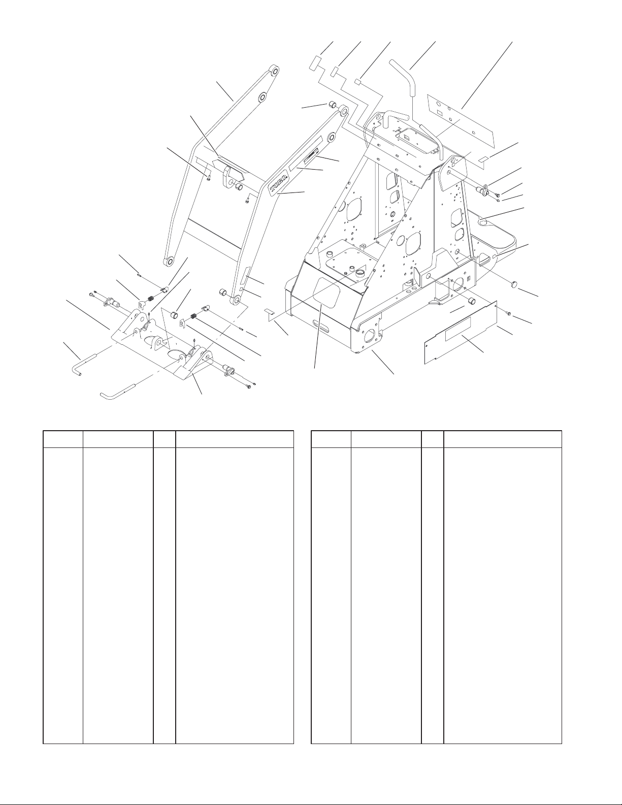
Frame and Loader Arm Assembly
DescriptionPart No. Qty.Ref. No. DescriptionPart No. Qty.Ref. No.
1 32144–70 6 Screw–HH
2 99–3020–01 2 Cover–Hose
3 105–8375 1 Frame ASM
3:2 98–4871 2 Bushing–Tension
3:3 98–9947 2 Tread–Foot
3:5 99–3157 1 Decal–Panel, Control
3:6 98–8219 1 Decal–Throttle
3:7 98–8220 1 Decal–Limiter, Speed
3:8 105–8432 1 Decal–Oil, Hydraulic
3:9 98–8235 1 Decal–Selector
3:10 98–4677 1 Decal–Power,
Auxiliary
4 105–8366 1 Loader ASM
4:2 32144–70 2 Screw–HH
4:3 98–4871 7 Bushing–Tension
4:4 98–4682 1 Decal–Caution
4:6 100–6141 4 Decal–Pinch
5 302–5 4 Fitting–Grease
6 99–5105 4 Bolt–Shoulder
7 99–1414 4 Pin–Pivot
8 105–8364 1 Quick Attach ASM
8:1 105–0245–03 1 Mount–Attach, Quick
8:2 105–8367 2 Pin–Locking
8:3 3285–1 2 Pin–Grooved
8:4 105–0246 2 Cam
8:5 98–4694 2 Spring–Compression
8:6 104–5909 1 Stop–RH
8:7 302–5 2 Fitting–Grease
8:8 98–4871 1 Bushing–Tension
8:9 104–5903 1 Stop–LH
10 98–4845 2 Grip–Cushion
12 105–8429 2 Decal–4 Paw
13 94–1402 2 Plug–Hole
20 105–8428 2 Decal–Dingo 320d
22 62–5550 1 Decal
23 93–7340 2 Decal–Toro
25 93–9084 6 Decal–Point, Lift
4
13
3329–109
11
10
12
9
8
7
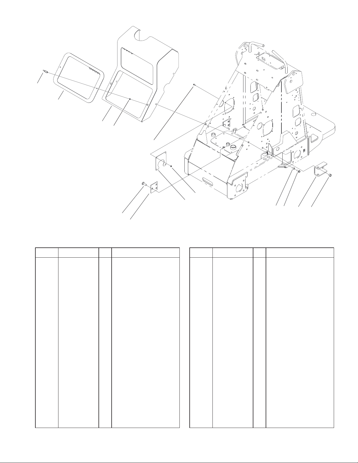
Hood and Screen Assembly
DescriptionPart No. Qty.Ref. No. DescriptionPart No. Qty.Ref. No.
1 3296–23 6 Nut–Lock, NI
2 100–4122–01 2 Bracket–Anchor
3 3234–29 4 Screw–HHF
4 32148–8 4 Insert–Threaded
5 3296–2 4 Nut–Lock
6 99–1427–03 1 Guard–Muffler
7 100–4116–01 2 Plate–Anchor
8 3233–26 6 Screw–CARR
9 3229–34 4 Bolt–CARR
10 99–3120–03 1 Hood ASM
11 99–3118–03 1 Cover ASM
12 99–3058 2 Washer
13 74–5950 2 Latch–Swell
5
6
4
3
2
1
Sheet No.: 3
5
3329–109
5:3
5:2
4:2
4
3
5
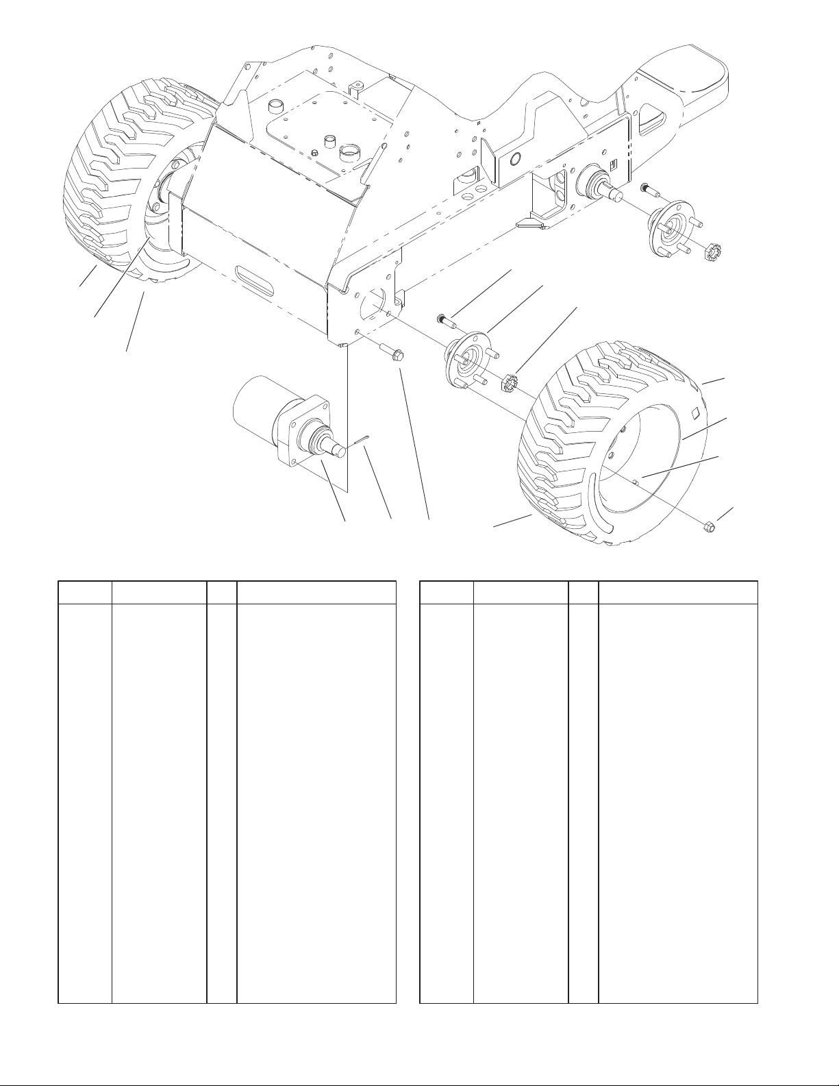
Wheel and Motor Assembly
DescriptionPart No. Qty.Ref. No. DescriptionPart No. Qty.Ref. No.
1 242–50 20 Nut–Lug
2 98–2747 2 LH Wheel And Tire
ASM
2:1 232–27 1 Stem–Valve
2:2 98–2748 1 Wheel
2:3 98–2749 1 Tire–Loader Style
3 99–3139 4 Nut
4 99–3064 4 Hub ASM
4:2 10–6830 5 Stud–Type, Drive
5 99–1447 2 RH Wheel And Tire
ASM
5:1 232–27 1 Stem–Valve
5:2 98–2748 1 Wheel
5:3 98–2749 1 Tire–Loader Style
6 99–3052 4 Hydraulic Motor ASM
7 99–3171 4 Pin–Cotter
8 3234–27 16 Screw–Flange
2:3
2:2
2:1 LH
5:1 RH
1
8
6
7
2
Sheet No.: 4
6
3329–109
1:1
1:2
1:3
1:4
1:5
2
3
1:6
4
Parts not listed in
part list are not
serviced separately
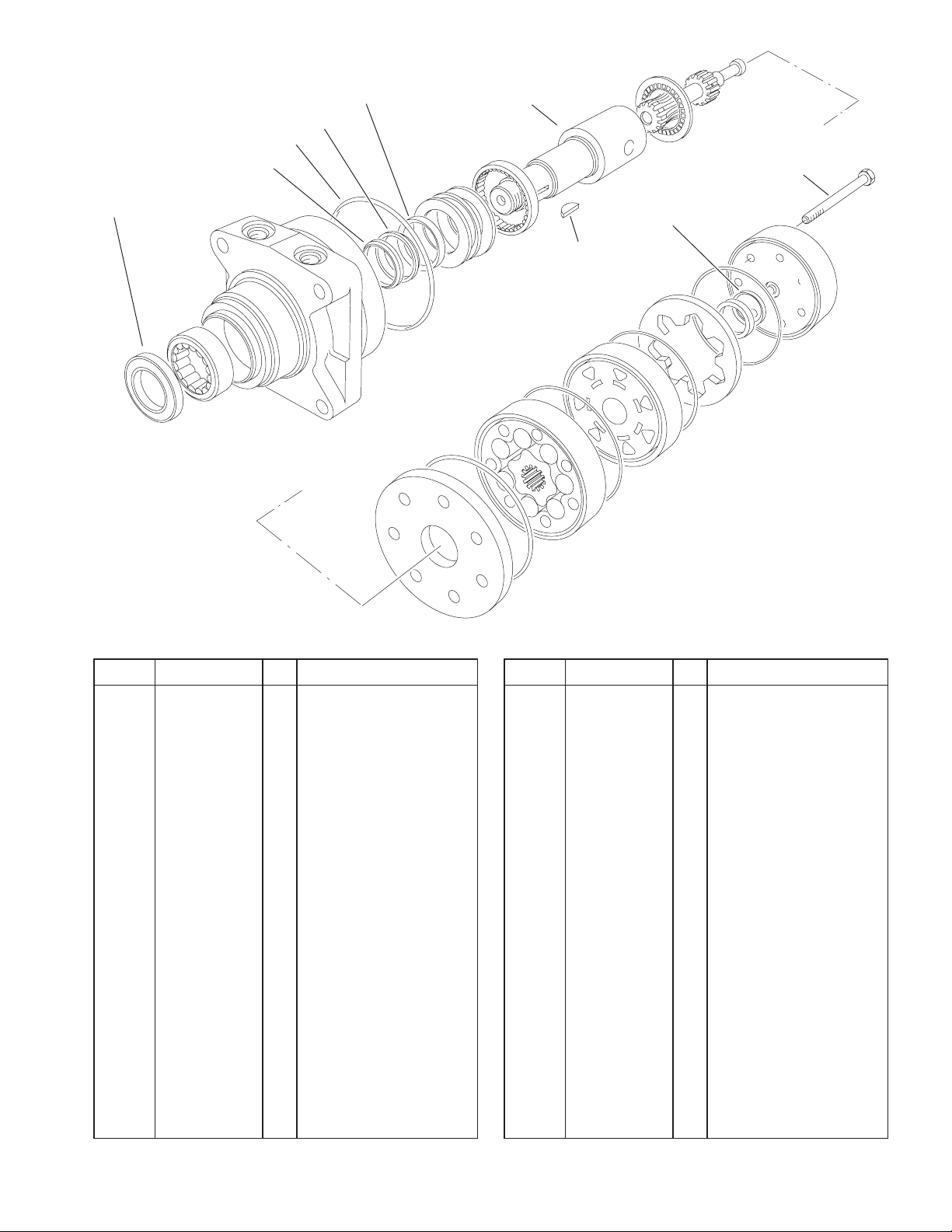
Hydraulic Motor Assembly No. 99–3052
DescriptionPart No. Qty.Ref. No. DescriptionPart No. Qty.Ref. No.
1 94–8178 1 Seal Kit
1:1 1 Seal–Dirt And Water
1:2 1 Washer–Backup
1:3 5 Seal–Ring
1:4 1 Washer–Backup
1:5 1 Seal–Inner
1:6 1 Seal–Commutator
2 99–3090 1 Coupling–Shaft
3 99–3091 7 Screw–Cap, HH
4 3257–42 1 Key–Woodruff
Sheet No.: A1
C–2980
Not serviced separately
7
3329–109
31
23
22
21
20
19:1
30
24
25
26:2
26:3
27
26
21:1
14
28
13
38
36
35
42
34
40
31
30
29
8
6
7
33
10
11
36
12
2
37
43
1
41
36
39
2
3
9
32
4
5
19
18
17
16
16:1
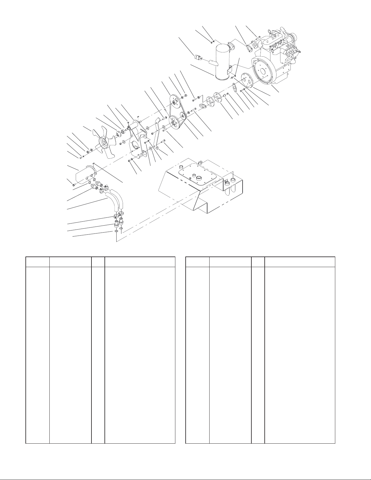
Engine Assembly
DescriptionPart No. Qty.Ref. No. DescriptionPart No. Qty.Ref. No.
1 98–4661 1 Engine–Kubota,
D722–E
2 99–5131 9 Bolt
3 99–1430 2 Spacer–Coupler
4 44–2230 2 Coupling–Rubber
5 323–10 1 Screw–HH
6 63–8140 1 Pulley–Idler
7 92–8876 1 V–Belt
8 3241–5 2 Screw–Set
9 104–9469 2 Nut–Lock
10 323–8 1 Screw–HH
11 100–1727–01 1 Mount–Tensioner
12 99–5121 4 Spacer
13 3256–24 2 Washer–Flat
14 3296–39 3 Nut–Lock, NI
16 354–78 2 Connector–Hose
16:1 237–146 1 O–Ring
17 2412–111 4 Clamp
18 99–3046 2 Hose–Suction,
Formed
19 99–3017 2 Fitting
19:1 237–81 1 O–Ring
20 66–9300 2 Screw–HF
21 98–4702 1 Pump–Gear, Tandem
21:1 98–4700 1 Key–Square
*21:2 99–1353 1 Kit–Seal
Sheet No.: 5
22 321–2 4 Screw–HH
23 3253–3 4 Washer–Lock
24 43–1911 1 Fan
25 105–8383 1 Adapter–Fan
26 99–1449 1 Pump Mount ASM
26:2 98–0068 1 Shaft–Fan
26:3 38–7820 2 Bearing–Ball
27 100–1715 2 Key–Square
28 3231–5 1 Screw–CARR
29 99–5111 2 Pulley–Keyed
30 33096–00 2 Washer–Flat
31 98–8089 2 Nut–Lock
32 71–4411 4 Spacer
33 5–1470 2 Capscrew
34 105–8390 1 Muffler–Diesel
35 3217–6 3 Nut–Hex
36 3253–4 12 Washer–Lock
37 100–2238 1 Gasket–Muffler
38 322–9 3 Screw–HH
39 99–5132 1 Bolt
40 99–5133 2 Bolt
41 99–1431 1 Adapter–Flywheel
42 75–6880 1 Screen–Arrester,
Spark
43 88–7200 1 Washer–Flat
* Not illustrated
8
20
22
21
19
13
24
14
31
27
17
16
3329–109
30
29
28
5
6
4
3
2
26
7
23
9
10
11
8
12
14
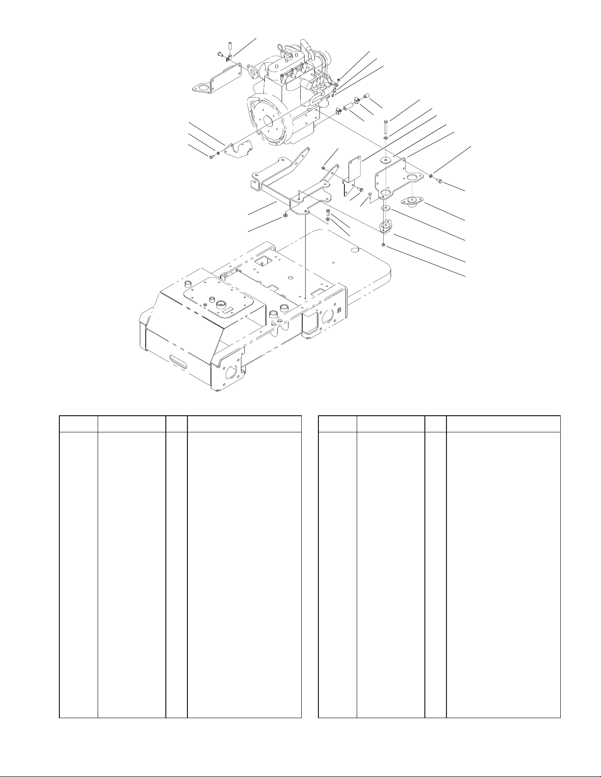
Engine Mount Assembly
DescriptionPart No. Qty.Ref. No. DescriptionPart No. Qty.Ref. No.
2 56–2230 1 Hose–Fuel
3 2412–36 2 Clamp–Hose
4 99–1445 1 Plug–Oil
5 323–13 4 Screw–HH
6 3256–24 4 Washer–Flat
7 87–5100 4 Washer–Snubbing
8 98–4596 4 Washer–Mount,
Engine
9 42–9600 6 Lockwasher–Spring
10 99–5130 8 Bolt
11 83–1030 2 Mount–Engine
12 93–5265 2 Mount–Engine
13 32128–29 4 Locknut–Flange
14 3296–29 10 Nut–Lock, NI
16 3256–80 4 Washer–Flat
17 95–1726 4 Screw–Taptite
W/Patch
19 98–0066–01 1 Mount–Engine
20 105–4054–01 1 Mount–Solenoid
21 99–5132 2 Bolt
22 3253–4 2 Washer–Lock
23 98–0055–01 2 Plate–Mount, Engine
24 2412–138 1 R–Clamp
26 98–0059–01 1 Mount–Filter,Fuel
27 322–5 8 Screw–HH
28 25–8640 1 Screw–HH
Sheet No.: 6
29 93–0021 1 Swivel–Cable, Throttle
30 3296–13 1 Nut–Lock NI
31 3234–29 2 Screw–HHF
9
3329–109
1
2
2
24
15:1
1025
26
23
19
22
12:3
15
3
6
30
3
6
31
3
32
28
27
12
3
4
15
16
17
11:2
3
18
4
11:1
11:3:1
11:3
21
20
28
27
8
3
9
6
5
10
11
29
13
14
Sheet No.: 7
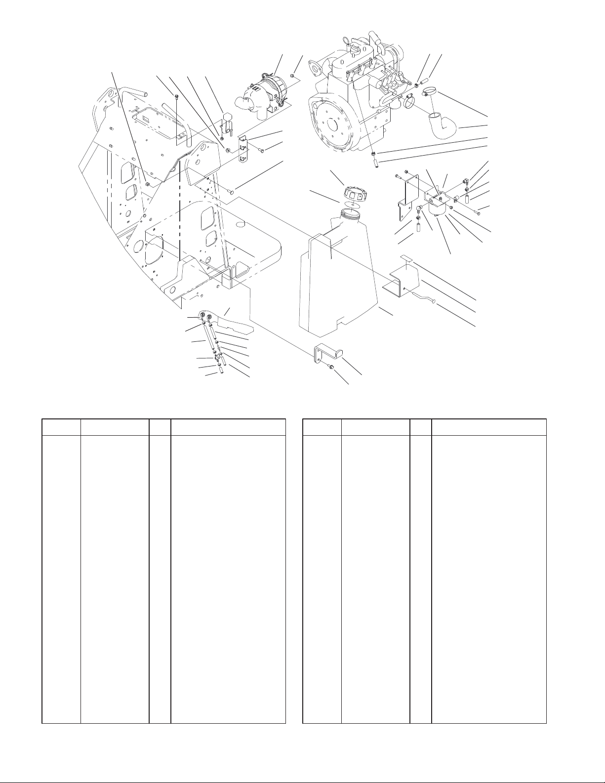
Fuel Tank and Air Filter Assembly
DescriptionPart No. Qty.Ref. No. DescriptionPart No. Qty.Ref. No.
1 99–3160 1 Air Cleaner ASM
2 3296–29 3 Nut–Lock, NI
3 92–2379 8 Clamp–Hose
4 63–7627 1 Hose–Fuel
5 321–6 2 Screw–HH
6 47–2980 2 Hose–Fuel
8 304–96 1 Elbow
9 2412–73 1 Clamp–R
10 3296–42 4 Nut–Lock, NI
11 63–7650 1 Separator–Filter/Water
11:1 63–8280 1 Head ASM
11:2 63–8290 1 Vent–Air
11:3 63–8300 1 Element–Spin–On
11:3:1 63–8310 1 Valve–Drain
12 104–7419 1 Cap–Fuel, Diesel
12:3 104–7420 1 Gasket–Vented
13 99–1444–03 1 Plate–Mount, Left
14 98–4657 1 Bolt–Mount
15 105–8438 1 Fuel Tank ASM, Diesel
LH
15:1 103–2615 2 Fitting–Fuel, Bulkhead
16 98–4656–03 1 Mount–Bottom, Tank
17 32144–70 2 Screw–HH
18 353–781 1 Fitting–Elbow
19 322–3 2 Screw–HH
20 99–5041 1 Hose–Cleaner, Air
21 2412–92 2 Clamp–Hose
22 3230–2 2 Bolt–CARR
23 99–3080–03 1 Mount–Cleaner, Air
24 32128–20 2 Nut–HF
25 3234–33 2 Screw–HHF
26 99–1422 1 Control–Throttle
27 99–3498 1 Return–Line, Fuel
28 2412–80 2 Clamp–Line, Fuel
29 93–6680 1 Decal–Diesel
30 1–603770 1 Valve–Fuel
31 99–5101 1 Hose–Fuel
32 106–8150 1 Fitting–Straight
10
3329–109
2
4
1
7
6
8
5
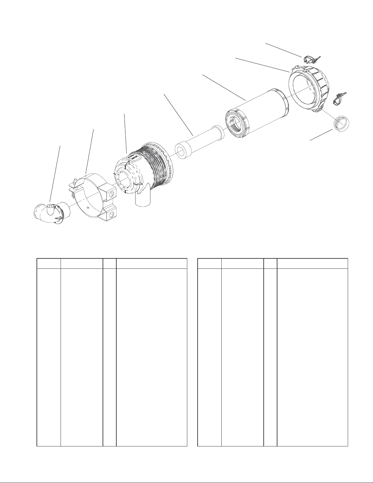
Air Cleaner Assembly No. 99–3160
DescriptionPart No. Qty.Ref. No. DescriptionPart No. Qty.Ref. No.
1 99–3173 1 Element–Filter, Air
2 99–3174 2 Clip–Cleaner, Air
3 99–3175 1 Valve–Ejector, Dust
4 99–3176 1 Cover
5 99–3183 1 Tube ASM
6 99–3184 1 Housing
7 99–3198 1 Filter–Safety
8 99–3197 1 Mounting Bracket ASM
3
Sheet No.: A3
C–3006
11
3329–109
5:2
17
10
9
19
16
12
11
9
10
6
7
8
13
14
15
5
3
2
4
5:3
1
Sheet No.: 8
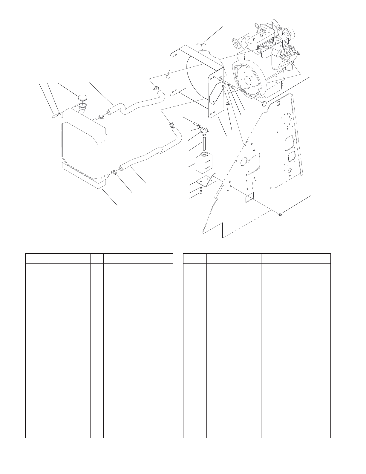
Radiator Mount Assembly
DescriptionPart No. Qty.Ref. No. DescriptionPart No. Qty.Ref. No.
1 32144–70 6 Screw–HH
2 3256–82 8 Washer–Flat
3 322–1 8 Screw–HH
5 104–4648 1 Mount–Radiator
5:2 93–6681 1 Decal–Warning, Fan
5:3 94–1402 1 Plug–Hole
6 93–2048 1 Cap–Tank, Overflow
7 94–1348 1 Hose–Fuel
8 93–2049 1 Tank–Overflow
9 71–3383 1 Hose–Fuel
10 92–2379 3 Clamp–Hose
11 99–5042 1 Hose–Radiator, Lower
12 2412–34 4 Clamp–Hose
13 99–1446–01 1 Mount–Tank, Overflow
14 3256–23 2 Washer–Flat
15 99–5132 2 Bolt
16 99–5125 1 Radiator ASM
17 66–3240 1 Cap–Radiator
19 99–5043 1 Hose–Radiator, Upper
12
1
2
3
3329–109
15
15:1
25
24
26
7
8
9
12
13
14
21
20
5
4
18
11
11:1
22
22:1
6
16:1
16
19:1
19
17
23
27
27:1
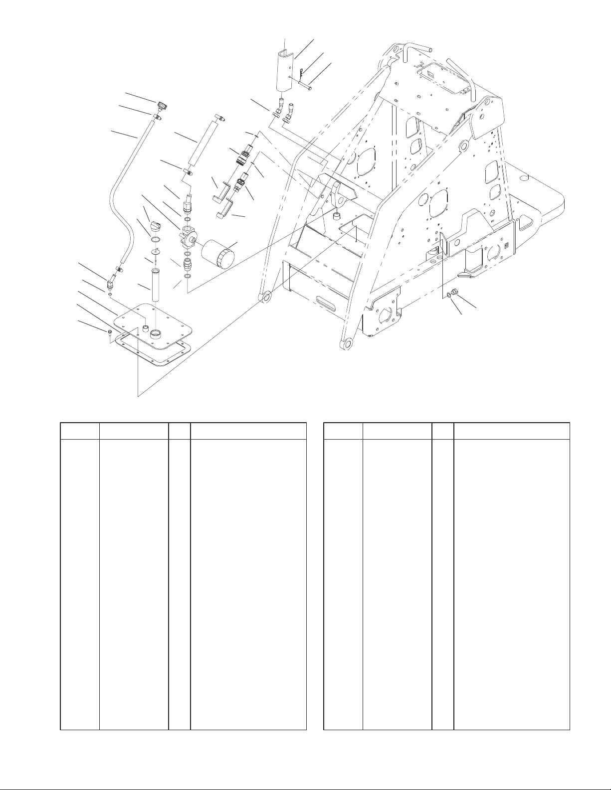
Hydraulic Tank and Filter Assembly
DescriptionPart No. Qty.Ref. No. DescriptionPart No. Qty.Ref. No.
1 98–4675–01 2 Lock–Cylinder
2 3290–467 2 Pin–Hair
3 283–52 2 Pin–Clevis
4 2412–129 2 Clamp–Hose
5 98–2713 1 Hose–Suction, HYD
6 340–74 2 Locknut–Bulkhead
7 68–6150 1 Breather
8 2412–36 2 Clamp–Hose
9 100–1748 1 Hose–Vent
11 354–127 1 Elbow–45
11:1 237–81 1 O–Ring
12 92–5821 1 Filter Head ASM
13 93–7498 1 Plug–Plastic
14 237–123 1 O–Ring
15 354–126 1 Fitting–HYD, 45
15:1 237–79 1 O–Ring
16 105–8394 1 Bulkhead Coupler
ASM
16:1 237–65 1 O–Ring
*16:2 105–8396 1 Seal Kit
17 100–8815 1 Cap–Dust, Nipple
18 100–8816 1 Cap–Dust, Coupler
19 105–8395 1 Bulkhead Nipple ASM
19:1 237–65 1 O–Ring
*19:2 100–6120 1 Seal Kit
20 61–2790 1 Filter–Screen
Sheet No.: 9
21 100–2097 1 Dipstick–Oil
22 98–9906 1 Fitting–Thread,
Straight
22:1 237–81 2 O–Ring
23 54–0110 1 Filter–Oil,
Transmission
24 98–9927 1 Gasket–Cover
25 100–1713–01 1 Cover ASM
26 98–9940 10 Screw
27 353–988 1 Plug–Hex, Hollow
27:1 237–79 1 O–Ring
* Not illustrated
13
3329–109
5
1
2
3
4
18
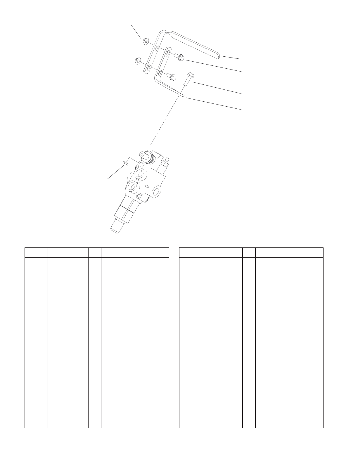
Auxiliary Control Lever Assembly
DescriptionPart No. Qty.Ref. No. DescriptionPart No. Qty.Ref. No.
1 98–9090 1 Grip–Control
2 3234–5 2 Screw
3 33104–030 1 Screw–HHF
4 99–1376 1 Mount–Control
5 32128–44 2 Nut
18 42–9580 1 Nut–Hex
Sheet No.: 10
14
23
22
4:2
22
4
12
20
D
21
4:1
12:1
12:2
D
C
25:1
14
33
3
4
C
A
25:2
B
12:2
12
12:1
25:2
1
25
11
6
19
18
15:2
13
4
4:2
3
3:1
2
18:1
E
17
5
16
15:1
15
E
14
18:1
4:1
3329–109
26
26:1
26:2
A
20
B
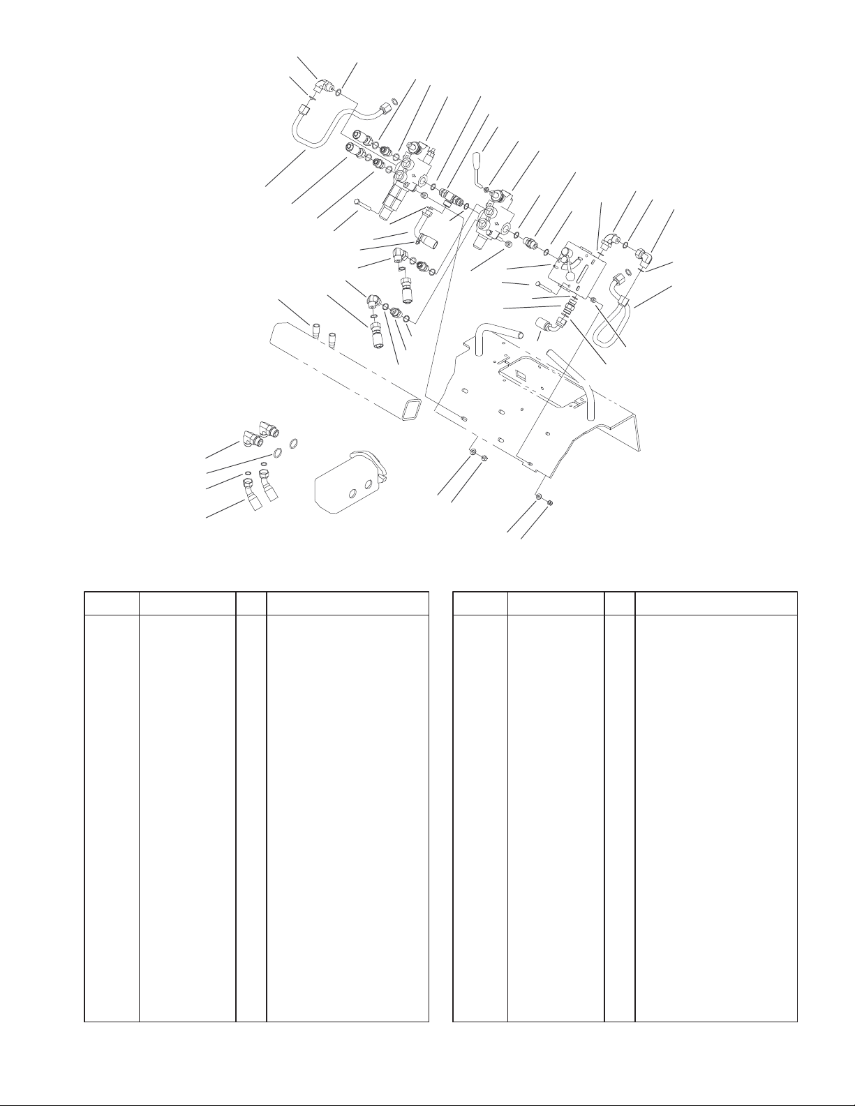
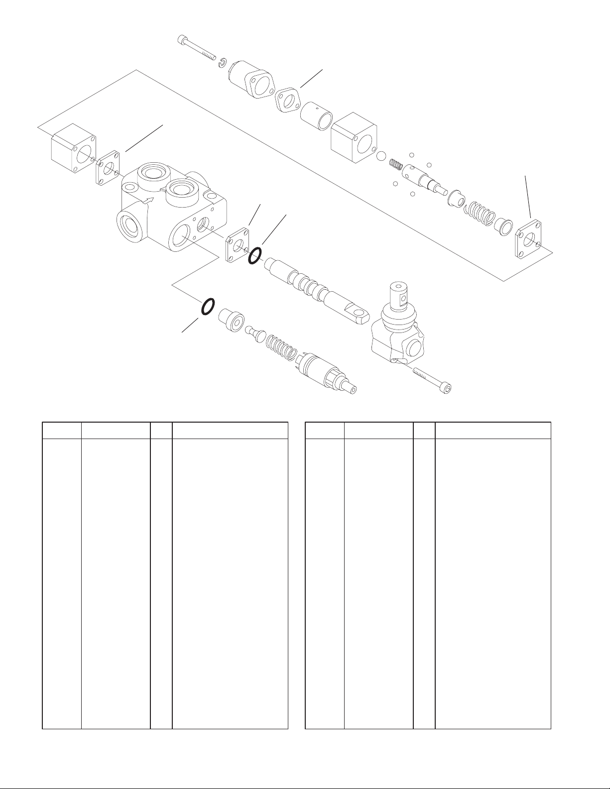
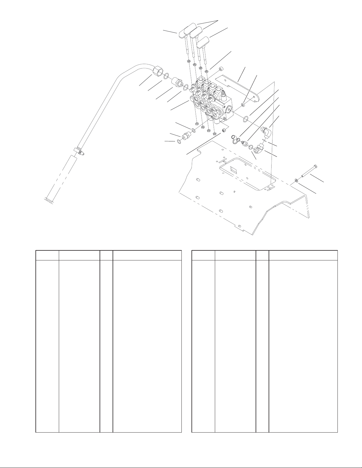
Hydraulic Valve Assembly
DescriptionPart No. Qty.Ref. No. DescriptionPart No. Qty.Ref. No.
1 99–3077 1 Valve–HYD, Auxiliary
2 99–3030 1 HYD Tube ASM
3 94–6031 2 Fitting–HYD
3:1 237–30 1 O–Ring
4 340–98 3 Fitting–HYD, 90
4:1 237–79 1 O–Ring
4:2 237–30 1 O–Ring
5 98–4695 4 Spacer
6 42–9580 1 Nut–Hex
11 98–4729 1 Lever–Valve
12 340–4 4 Adapter–HYD
12:1 237–30 1 O–Ring
12:2 237–79 1 O–Ring
13 98–4799 2 Tube–Spacer
14 100–2245 1 Hose ASM
15 98–4735 1 Valve–Check, HYD
15:1 237–30 1 O–Ring
15:2 237–79 1 O–Ring
16 321–14 2 Screw–HH
17 104–4221 1 Kit–Valve, HYD
18 95–3209 1 Fitting–Thread,
Straight
18:1 237–79 2 O–Ring
19 99–3072 1 Valve–Selector
20 100–1730 2 Hose–Pump, HYD
21 322–13 4 Screw–HH
28
29
27
30
22 100–8817 2 HYD Hose ASM
23 98–4724 1 HYD Tube ASM
25 98–9079 1 Adapter–Tee,
25:1 237–30 1 O–Ring
25:2 237–79 2 O–Ring
26 340–105 2 Fitting–HYD, 90
26:1 237–80 1 O–Ring
26:2 237–30 1 O–Ring
27 3256–22 2 Washer–Flat
28 3256–23 4 Washer–Flat
29 3296–29 4 Nut–Lock, NI
30 3296–42 2 Nut–Lock, NI
33 3290–379 18 Tie–Cable
Sheet No.: 11
Adjustable
15
3329–109
3:1
3:2
3:2
3:2
3
Parts not listed in
part list are not
serviced separately
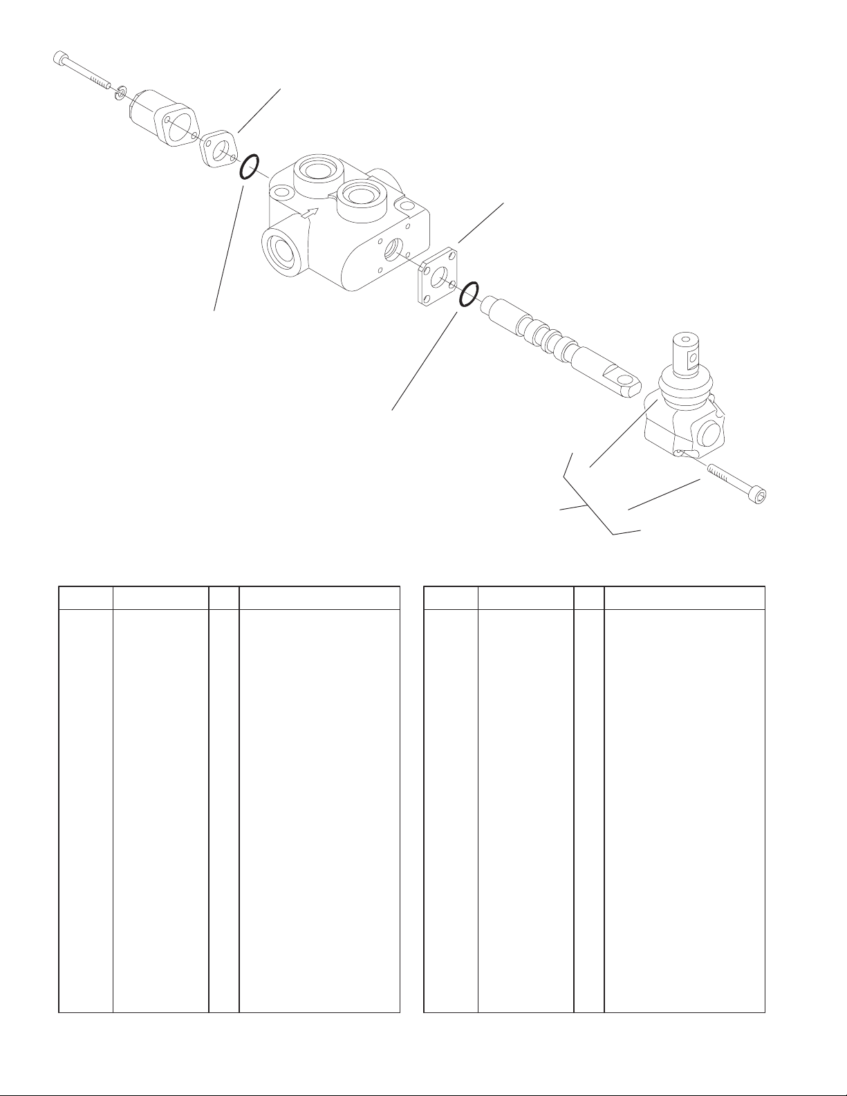
Hydraulic Valve Assembly No. 99–3077
3 99–4391 1 Seal Kit
3:1 99–3074 1 Gasket
3:2 99–3075 3 Gasket
3
Sheet No.: A4
C–2836
DescriptionPart No. Qty.Ref. No. DescriptionPart No. Qty.Ref. No.
16
1:1:1
3329–109
1:2:2
1:2:5
1:2:1
1:1:1
1:1:4
1:1
1
1:2
1:1:2
Parts not listed in
part list are not
serviced separately
Hydraulic Valve Assembly No. 104–4221
DescriptionPart No. Qty.Ref. No. DescriptionPart No. Qty.Ref. No.
1 1 Valve–Flow, Hydraulic
1:1 104–4231 1 Kit–Seal
1:1:1 2 O–Ring
1:1:2 2 Back–Up
1:1:3 2 O–Ring
1:1:4 2 Quad Ring
1:2 98–9098 1 Kit–Hardware, Handle
1:2:1 1 Handle
1:2:2 1 Knob
1:2:3 1 Screw–Thumb
1:2:5 2 Pin–Roll
3 3296–27 1 Nut–Lock NI
1:1:3
1:1:3
1:1:2
1:1:4
1:2:3
1:2:5
3
Sheet No.: A5
C–2982
Not serviced separately
17
3329–109
3:1
3:2
3
3
Parts not listed in
part list are not
serviced separately
Hydraulic Valve Assembly No. 99–3072
3 99–4391 1 Seal Kit
3:1 99–3074 1 Gasket
3:2 99–3075 3 Gasket
DescriptionPart No. Qty.Ref. No. DescriptionPart No. Qty.Ref. No.
6
4
5
Sheet No.: A6
C–2983
18
6
5
5
15
12
8
3329–109
9
7:1
7
7:2
14:1
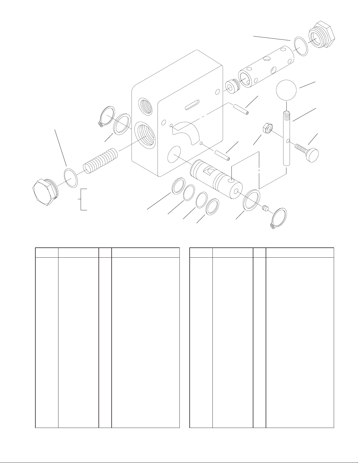
4–Spool Valve Assembly
DescriptionPart No. Qty.Ref. No. DescriptionPart No. Qty.Ref. No.
1 322–20 3 Screw–HH
2 86–5480 1 Nipple–Test
3 340–18 1 Fitting–HYD, 90
3:1 237–79 1 O–Ring
3:2 237–22 1 O–Ring
4 99–3070 1 Valve–HYD, 4–Spool
5 98–4671 2 Cylinder Handle ASM
6 98–4670 2 Drive Handle ASM
7 98–9921 1 Fitting–Thread,
Straight
7:1 237–145 1 O–Ring
7:2 237–79 1 O–Ring
8 99–3078 2 Spacer
9 99–3021 1 HYD Tube ASM
10 340–159 1 Fitting–HYD, 90
10:1 237–22 2 O–Ring
11 354–79 1 Cap–Dust
12 104–4222–03 1 Bracket–Cover, Mount
14 340–4 2 Adapter–HYD
14:1 237–30 1 O–Ring
14:2 237–79 1 O–Ring
15 42–9580 8 Nut–Hex
16 3256–23 3 Washer–Flat
17 3296–29 3 Nut–Lock, NI
18 98–4695 1 Spacer
4
14:2
14
17
10:1
3:1
11
2
3
3:2
10
1
16
Sheet No.: 12
19
3329–109
6
5
Parts not listed in
part list are not
serviced separately
Sheet No.: A7
C–2984
3:1 3:2
7
8
9
3:2
4
14
10
11
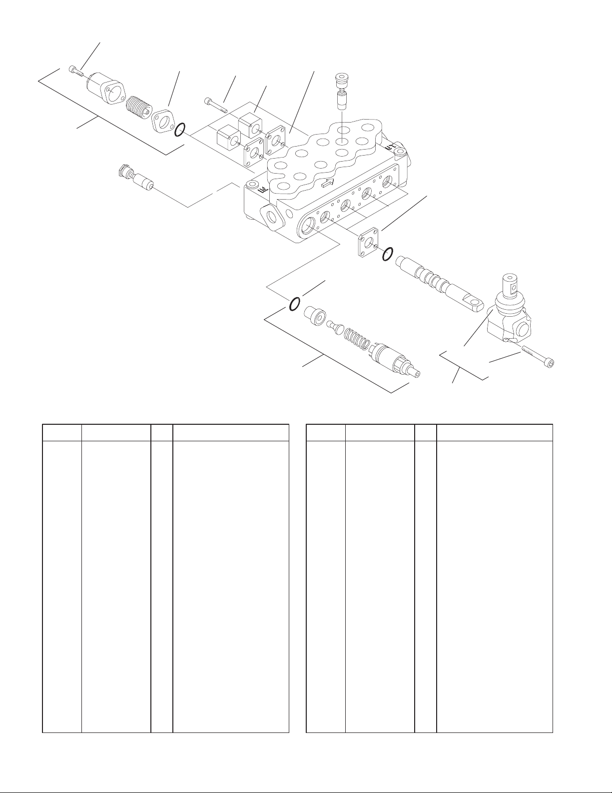
Hydraulic Valve Assembly No. 99–3070
DescriptionPart No. Qty.Ref. No. DescriptionPart No. Qty.Ref. No.
3 99–4390 1 Kit–Seal
3:1 99–3074 4 Gasket
3:2 99–3075 8 Gasket
5 100–8801 4 Kit–Spring, High Force
6 100–8802 8 Screw–Cap, End
7 100–8803 4 Screw
8 100–8804 2 Block–Mount, Switch
9 100–8805 1 Valve–Relief
10 100–8806 8 Screw
11 100–8807 4 Operator ASM
14 100–8829 4 Boot
20
 Loading...