

Page 1

FormNo.3409-583RevB
30inTurfMasterWalk-Behind
LawnMower
22210
Cortacéspeddirigido
TurfMasterde76cm(30")
22210
Tondeuseautotractée
TurfMasterde76cm(30
pouces)
22210
www.T oro.com.
*3409-583*B
Page 2
30inTurfMasterWalk-BehindLawnMower
G023543
1
ModelNo.22210—SerialNo.400000000andUp
FormNo.3409-564RevB
Operator'sManual
Introduction
Thisrotary-blade,walk-behindlawnmowerisintended
tobeusedbyresidentialhomeownersorprofessional,
hiredoperators.Itisdesignedprimarilyforcutting
grassonwell-maintainedlawnsonresidentialor
commercialproperties.Itisnotdesignedforcutting
brushorforagriculturaluses.
Readthisinformationcarefullytolearnhowtooperate
andmaintainyourproductproperlyandtoavoid
injuryandproductdamage.Youareresponsiblefor
operatingtheproductproperlyandsafely.
YoumaycontactT orodirectlyatwww.T oro.comfor
productandaccessoryinformation,helpndinga
dealer,ortoregisteryourproduct.
Wheneveryouneedservice,genuineToroparts,or
additionalinformation,contactanAuthorizedService
DealerorToroCustomerServiceandhavethemodel
andserialnumbersofyourproductready .Figure1
identiesthelocationofthemodelandserialnumbers
ontheproduct.Writethenumbersinthespace
provided.
seriousinjuryordeathifyoudonotfollowthe
recommendedprecautions.
g000502
Figure2
1.Safety-alertsymbol
Thismanualuses2wordstohighlightinformation.
Importantcallsattentiontospecialmechanical
informationandNoteemphasizesgeneralinformation
worthyofspecialattention.
WARNING
CALIFORNIA
Proposition65Warning
Thisproductcontainsachemical
orchemicalsknowntotheStateof
Californiatocausecancer,birthdefects,
orreproductiveharm.
Theengineexhaustfromthisproduct
containschemicalsknowntotheStateof
Californiatocausecancer,birthdefects,
orotherreproductiveharm.
Figure1
1.Themodelandserialnumberplateisinoneofthese2
locations.
ModelNo.
SerialNo.
Thismanualidentiespotentialhazardsandhas
safetymessagesidentiedbythesafety-alertsymbol
(Figure2),whichsignalsahazardthatmaycause
©2017—TheT oro®Company
8111LyndaleAvenueSouth
Bloomington,MN55420
CV
Registeratwww.Toro.com.
ItisaviolationofCaliforniaPublicResourceCode
Section4442or4443touseoroperatetheengineon
anyforest-covered,brush-covered,orgrass-covered
landunlesstheengineisequippedwithaspark
arrester,asdenedinSection4442,maintainedin
g023543
effectiveworkingorderortheengineisconstructed,
equipped,andmaintainedforthepreventionofre.
ThissparkignitionsystemcomplieswithCanadian
ICES-002.
TheenclosedEngineOwner'sManualis
suppliedforinformationregardingtheUS
EnvironmentalProtectionAgency(EPA)and
theCaliforniaEmissionControlRegulationof
emissionsystems,maintenance,andwarranty.
Replacementsmaybeorderedthroughtheengine
manufacturer.
NetTorque:Thegrossornettorqueofthisengine
waslaboratoryratedbytheenginemanufacturerin
OriginalInstructions(EN)
PrintedintheUSA
AllRightsReserved
*3409-564*B
Page 3

accordancewiththeSocietyofAutomotiveEngineers
(SAE)J1940.Asconguredtomeetsafety,emission,
andoperatingrequirements,theactualenginetorque
onthisclassofmowerwillbesignicantlylower.Goto
www.T oro.comtoviewspecicationsonyourmower
model.
Contents
Introduction...............................................................1
Safety.......................................................................2
GeneralSafety...................................................2
SafetyandInstructionalDecals..........................3
Setup........................................................................6
1InstallingtheHandle........................................6
2AdjustingtheHandleHeight.............................6
3FillingtheEnginewithOil.................................7
4AssemblingtheGrassBag...............................8
ProductOverview.....................................................9
Controls.............................................................9
Operation................................................................10
BeforeOperation.................................................10
BeforeOperationSafety...................................10
FillingtheFuelTank..........................................10
CheckingtheEngine-OilLevel...........................11
AdjustingtheCuttingHeight..............................11
CheckingtheBlade-StopSystem
Operation......................................................12
DuringOperation.................................................12
DuringOperatingSafety...................................12
StartingtheEngine...........................................13
ShuttingofftheEngine......................................13
OperatingtheSelf-PropelDriveand
EngagingtheCuttingBlades.........................13
RecyclingtheClippings....................................14
BaggingtheClippings.......................................14
Side-DischargingtheClippings.........................15
OperatingTips.................................................15
AfterOperation....................................................16
AfterOperatingSafety......................................16
CleaningundertheMachine.............................16
CleaningtheWheels.........................................17
Maintenance...........................................................18
RecommendedMaintenanceSchedule(s)...........18
MaintenanceSafety..........................................18
ServicingtheAirFilter.......................................19
ChangingtheEngineOil...................................19
ChangingtheOilFilter......................................20
ServicingtheSparkPlug...................................21
CheckingtheConditionoftheBelts...................21
EmptyingtheFuelTankandCleaningthe
Filter..............................................................21
ChangingtheFuelFilter....................................21
ServicingtheBlade-DriveSystem.....................22
ServicingtheCuttingBlades.............................22
ChangingtheBlade-DriveBelt..........................25
ChangingtheBlade-Brake-Clutch(BBC)
Belt................................................................26
AdjustingtheBlade-BrakeCable......................27
ChangingtheTransmissionBelt.......................28
AdjustingtheTransmission...............................28
AdjustingtheSelf-PropelCable........................29
Storage...................................................................29
GeneralInformation..........................................29
PreparingtheFuelSystem...............................29
PreparingtheEngine........................................30
RemovingtheMachinefromStorage................30
Troubleshooting......................................................31
Safety
Thismachinehasbeendesignedinaccordancewith
ANSIB71.1-2012.
GeneralSafety
Thisproductiscapableofamputatinghandsand
feetandofthrowingobjects.Alwaysfollowallsafety
instructionstoavoidseriouspersonalinjury .
Usingthisproductforpurposesotherthanitsintended
usecouldprovedangeroustoyouandbystanders.
•Readandunderstandthecontentsofthis
Operator’sManualbeforestartingtheengine.
•Donotputyourhandsorfeetnearmoving
componentsofthemachine.
•Donotoperatethemachinewithoutallguards
andothersafetyprotectivedevicesinplaceand
workingonthemachine.
•Keepclearofanydischargeopening.Keep
bystandersasafedistanceawayfromthe
machine.
•Keepchildrenoutoftheoperatingarea.Never
allowchildrentooperatethemachine.
•Stopthemachineandshutofftheenginebefore
servicing,fueling,oruncloggingthemachine.
Improperlyusingormaintainingthismachinecan
resultininjury.T oreducethepotentialforinjury,
complywiththesesafetyinstructionsandalwayspay
attentiontothesafety-alertsymbol,whichmeans
Caution,Warning,orDanger—personalsafety
instruction.Failuretocomplywiththeseinstructions
mayresultinpersonalinjuryordeath.
Youcanndadditionalitemsofsafetyinformationin
theirrespectivesectionsthroughoutthismanual.
2
Page 4
SafetyandInstructionalDecals
Safetydecalsandinstructionsareeasilyvisibletotheoperatorandarelocatednearanyarea
ofpotentialdanger.Replaceanydecalthatisdamagedormissing.
Manufacturer'sMark
1.Indicatesthatthebladeisidentiedasapartfromthe
originalmachinemanufacturer .
93-7009
1.Warning—Donotoperatethemowerwiththedeectorup
orremoved;keepthedeectorinplace.
2.Cutting/dismembermenthazardofhandorfoot,mower
blade—stayawayfrommovingparts.
decaloemmarkt
decal116-7581
116-7581
1.Cutting/dismembermenthazardofhandorfoot,mower
blade-stayawayfrommovingparts.ReadtheOperator’s
Manualbeforeadjustingservicing,orcleaning.
decal93-7009
94-8072
1.Warning—cutting/dismembermenthazardofhandorfoot,
cuttingmechanism.
116-7127
decal94-8072
decal116-7127
3
Page 5
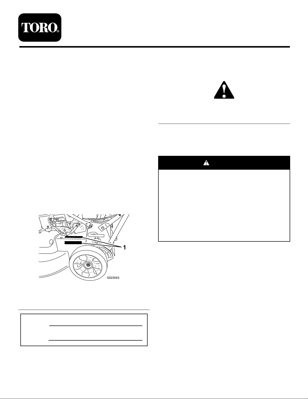
decal116-7583
116-7583
1.Warning–ReadtheOperator’sManual.Donotoperatethis
machineunlessyouaretrained.
2.Thrownobjecthazard—keepbystandersasafedistance
awayfromthemachine.
3.Thrownobjecthazard—Donotoperatethemachinewithout
thereardischargeplugorbaginplace.
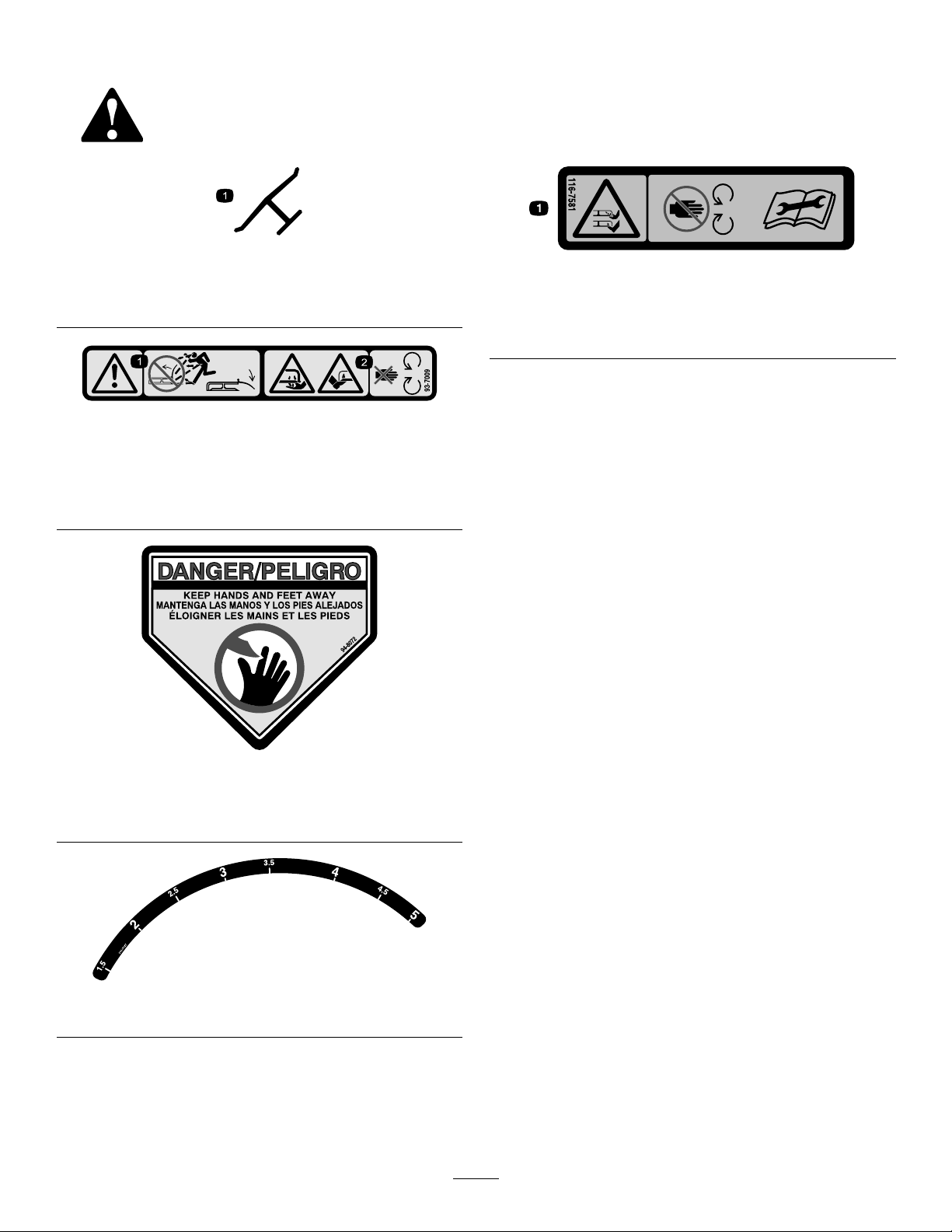
116-8528
1.ReadtheOperator’s
Manualbeforeperforming
anymaintenance.
2.Checkbelttensionevery
50operatinghours.
4.Cutting/dismembermenthazardofhandorfoot,mower
blade—stayawayfrommovingparts;keepallguardsinplace.
5.Warning—wearhearingprotection.
6.Cutting/dismembermenthazardofhandorfoot,mower
blade—Donotoperateupanddownslopes;operateside
tosideonslopes;shutofftheenginebeforeleavingthe
operatingposition—pickupobjectsthatcouldbethrownby
theblades;andlookbehindyouwhenbackingup.
decal120-9570
120-9570
1.Warning—stayawayfrommovingparts;keepallguards
andshieldsinplace.
decal116-8528
decal121-1449
121-1449
1.ReadtheOperator's
2.Firehazard
Manual.
1.Warning—donotparkonslopesunlesswheelsarechocked
orblocked.
decal116-9313
116-9313
3.T oxicgasinhalation
hazard
4.Hotsurface;burnhazard
decal117-2718
117–2718
4
Page 6
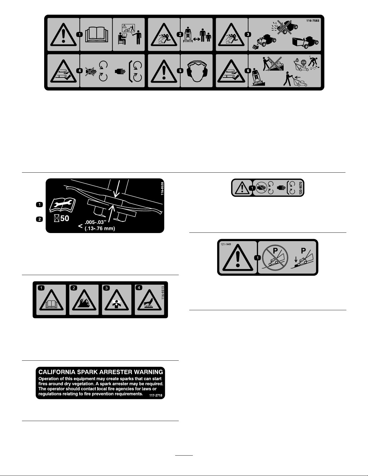
decal121-5846
121–5846
1.Height-of-cut
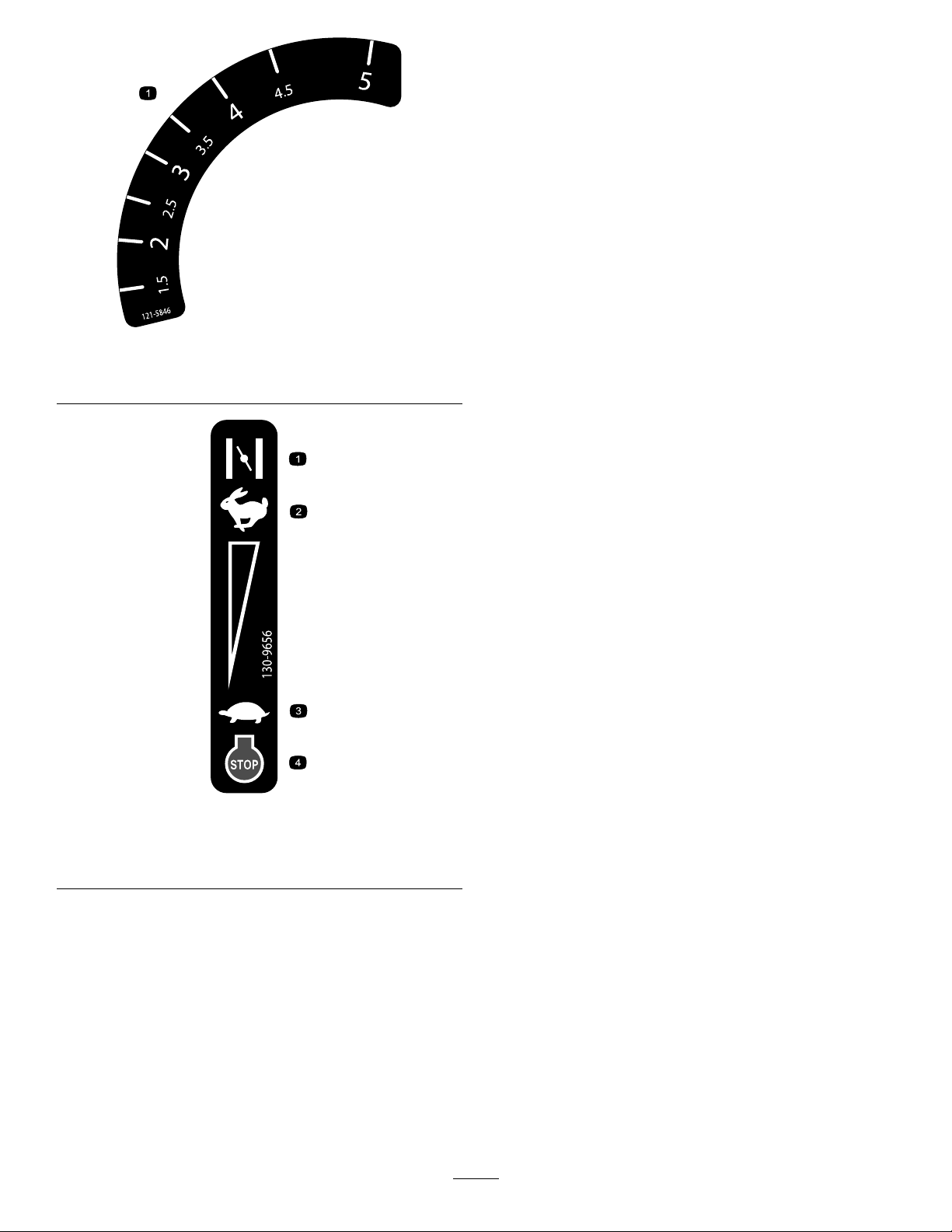
130-9656
1.Choke3.Slow
2.Fast4.Engine—stop
decal130-9656
5
Page 7
Setup
G019802
1
2
G027930
2
1
3
Important:Removeanddiscardtheprotective
plasticsheetthatcoverstheengineandanyother
plasticorwrappingonthemachine.
1
InstallingtheHandle
NoPartsRequired
Procedure
WARNING
g027930
Figure4
Foldingorunfoldingthehandleimproperly
candamagethecables,causinganunsafe
operatingcondition.
•Donotdamagethecableswhenfoldingor
unfoldingthehandle.
•Ifacableisdamaged,contactan
AuthorizedServiceDealer.
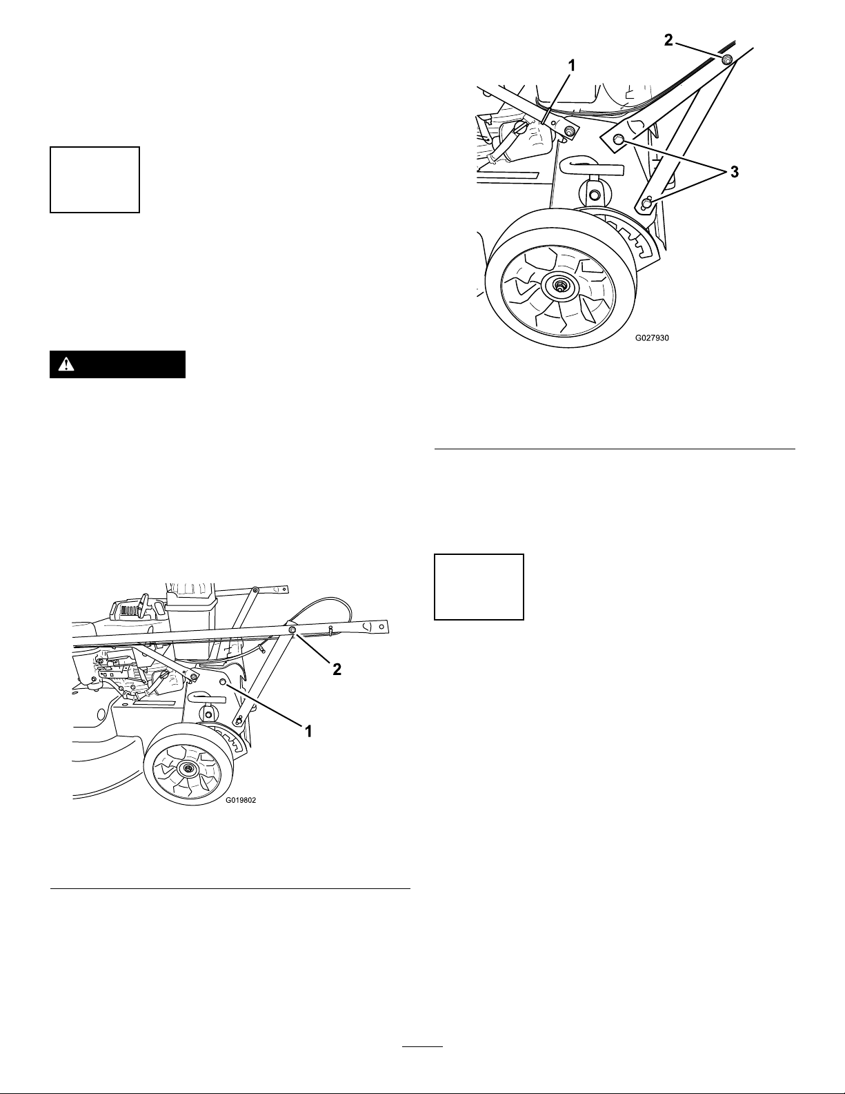
1.Removethe2boltsfromthemachineframein
thelocationshowninFigure3.
1.Bolt(2)
Figure3
2.Nutonhandlesupport
bracket(2)
1.Cabletie3.Bolt(4)
2.Nutonhandlesupport
bracket(2)
5.Useacabletietosecurethecablestothelower
handleinthelocationshowninFigure4.
6.Securethecabletieonthehandleandtrimoff
theexcessmaterialfromthetie.
2
AdjustingtheHandle Height
NoPartsRequired
Procedure
1.Standintheoperatingpositiontodeterminethe
g019802
mostcomfortablehandleheight.
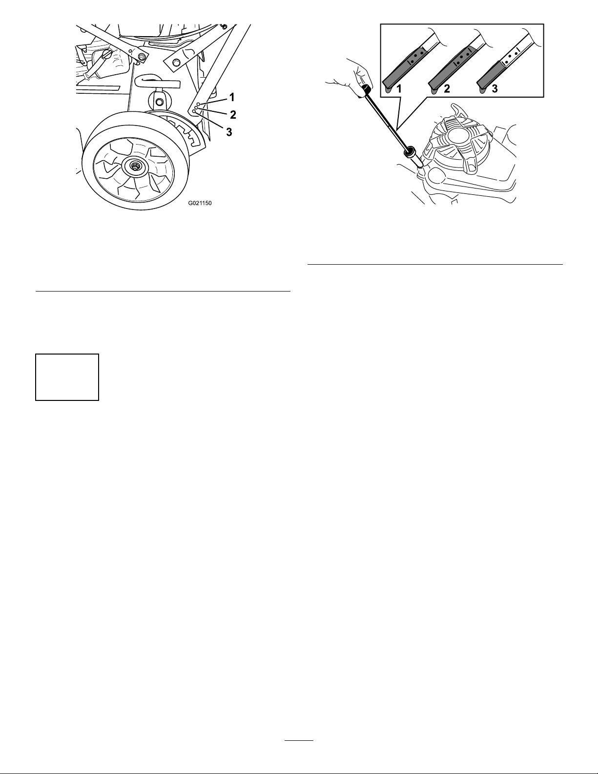
2.Removethehandleboltandinsertitin1of
the3holeslocatedatthebottomofthehandle
bracket(Figure5).
2.Rotatethehandlerearwardtotheoperating
position.
3.Securethehandletothemachinewiththebolts
thatyouremovedinstep1
4.Tightenthefastenersthatsupportthehandleon
bothsidesofthemachineasshowninFigure4.
6
Page 8
G021 150
1
2
3
Figure5
1.Lowesthandleheight
setting
2.Middlehandleheight
setting
3.Tightenthehandleboltuntilitissnug.
4.Repeatthestepsabovefortheothersideofthe
machine.
3.Highesthandleheight
setting
g021150
1.Full3.Low
2.High
3.Carefullypourabout3/4oftheenginecapacity
ofoilintotheoil-lltube.
4.Waitabout3minutesfortheoiltosettleinthe
engine.
5.Wipethedipstickcleanwithacleancloth.
6.Insertthedipstickintotheoil-lltube,then
removethedipstick.
Figure6
g194742
3
FillingtheEnginewithOil
NoPartsRequired
Procedure
Important:Y ourmachinedoesnotcomewithoil
intheengine.Beforestartingtheengine,llthe
enginewithoil.
Engineoilcapacity:Withoillter:0.85L(29oz);
withoutoillter:0.65L(22oz)
Oilviscosity:SAE30orSAE10W-30detergentoil
APIserviceclassication:SJorhigher
1.Movethemachinetoalevelsurface.
2.Removethedipstickbyrotatingthecap
counterclockwiseandpullingitout(Figure6).
7.Readtheoillevelonthedipstick(Figure6).
•IftheoillevelisbelowtheAddmarkonthe
dipstick,carefullypourasmallamountof
oilintotheoil-lltube,wait3minutes,and
repeatsteps3through5untiltheoillevelis
attheFullmarkonthedipstick.
•IftheoillevelisabovetheFullmarkonthe
dipstick,draintheexcessoiluntiltheoillevel
isattheFullmarkonthedipstick;referto
ChangingtheEngineOil(page19).
Important:Iftheoillevelintheengine
istoolowortoohighandyourunthe
engine,youmaydamagetheengine.
8.Installthedipstickintotheoil-lltubesecurely.
7
Page 9
4
g027717
1
2
3
g027718
AssemblingtheGrassBag
NoPartsRequired
Procedure
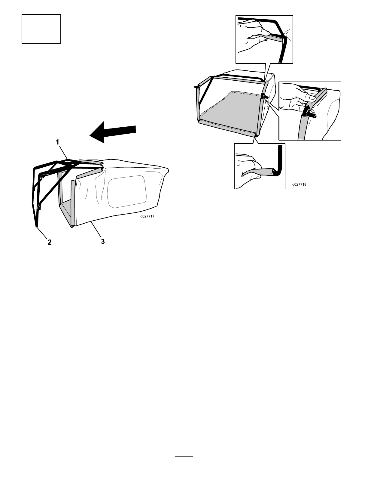
1.Slipthegrassbagovertheframeasshownin
Figure7.
g027718
Figure8
Figure7
1.Handle
2.Frame
3.Grassbag
Note:Donotslipthebagoverthehandle
(Figure7).
2.Hookthebottomchannelofthebagontothe
bottomoftheframe(Figure8).
3.Hookthetopandsidechannelsofthebagonto
thetopandsidesoftheframe,respectively
(Figure8).
g027717
8
Page 10
ProductOverview
g019644
1
2
3
4
g019652
1 2
3
4
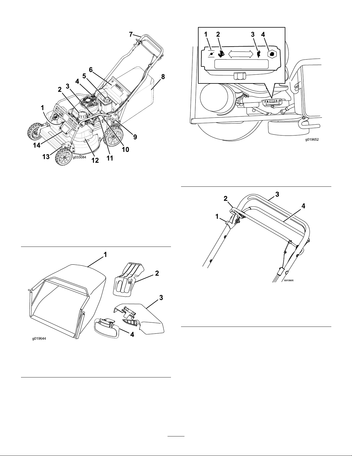
Controls
g019652
Figure11
Throttle(Throttlelevernotshownforthesakeofclarity)
Figure9
1.Sparkplug(underbrush
guard)
2.Airlter
3.Throttlelever
4.Oilll/dipstick11.Oillter
5.Fuel-tankcap12.Beltcover
6.Reardoor13.Frontcutting-heightlever
7.Handle14.Belt-cover-accesspanel
8.Grassbag
9.Rearcutting-heightlever
10.Fuel-shutoffvalve
g033084
1.Choke3.Slow
2.Fast
4.Stop
g012605
Figure12
Controlbar
1.Blade-controllock-lever3.Handle
2.Blade-controlbail4.Drivebail
1.Grassbag3.Side-dischargechute
2.Rear-dischargeplug
Figure10
4.Side-dischargedoor
g019644
9
Page 11
Operation
BeforeOperation
BeforeOperationSafety
GeneralSafety
WARNING
Fuelisharmfulorfatalifswallowed.
Long-termexposuretovaporscancause
seriousinjuryandillness.
•Avoidprolongedbreathingofvapors.
•Keepyourhandsandfaceawayfromthe
nozzleandthefuel-tankopening.
•Keepfuelawayfromyoureyesandskin.
•Becomefamiliarwiththesafeoperationofthe
equipment,operatorcontrols,andsafetysigns.
•Checkthatallguardsandsafetydevices,suchas
deectorsand/orgrasscatcher,areinplaceand
workingproperly.
•Alwaysinspectthemachinetoensurethatthe
blades,bladebolts,andcuttingassemblyarenot
wornordamaged.
•Inspecttheareawhereyouwillusethemachine
andremoveallobjectsthatthemachinecould
throw.
•Adjustingthecuttingheightmaybringyouinto
contactwiththemovingblade,causingserious
injury.
–Shutofftheengineandwaitforallmoving
partstostop.
–Donotputyourngersunderthehousing
whenadjustingthecuttingheight.
FuelSafety
DANGER
Fuelisextremelyammableandhighly
explosive.Areorexplosionfromfuel
canburnyouandothersandcandamage
property.
FillingtheFuelTank
•Forbestresults,useonlyclean,fresh(lessthan
30daysold),unleadedgasolinewithanoctane
ratingof87orhigher((R+M)/2ratingmethod).
•Oxygenatedfuelwithupto10%ethanolor15%
MTBEbyvolumeisacceptable.
•Ethanol:Gasolinewithupto10%ethanol
(gasohol)or15%MTBE(methyltertiarybutyl
ether)byvolumeisacceptable.Ethanoland
MTBEarenotthesame.Gasolinewith15%
ethanol(E15)byvolumeisnotapprovedforuse.
Neverusegasolinethatcontainsmorethan10%
ethanolbyvolume,suchasE15(contains15%
ethanol),E20(contains20%ethanol),orE85
(containsupto85%ethanol).Usingunapproved
gasolinemaycauseperformanceproblemsand/or
enginedamagewhichmaynotbecoveredunder
warranty.
•Donotusegasolinecontainingmethanol.
•Donotstorefueleitherinthefueltankorinfuel
containersoverthewinterunlessafuelstabilizer
isused.
•Donotaddoiltogasoline.
Important:T oreducestartingproblems,addfuel
stabilizertothefuelallseason,mixingitwith
gasolinelessthan30daysold.
Refertoyourenginemanualforadditionalinformation.
•Topreventastaticchargefromignitingthe
fuel,placethecontainerand/ormachine
directlyonthegroundbeforelling,notin
avehicleoronanobject.
•Fillthefueltankoutdoors,inanopenarea,
whentheengineiscold.Wipeupanyfuel
thatspills.
•Donothandlefuelwhensmokingor
aroundanopenameorsparks.
•Storefuelinanapprovedcontainerand
keepitoutofthereachofchildren.
g209575
Figure13
1.Fuel-tankcap
10
Page 12
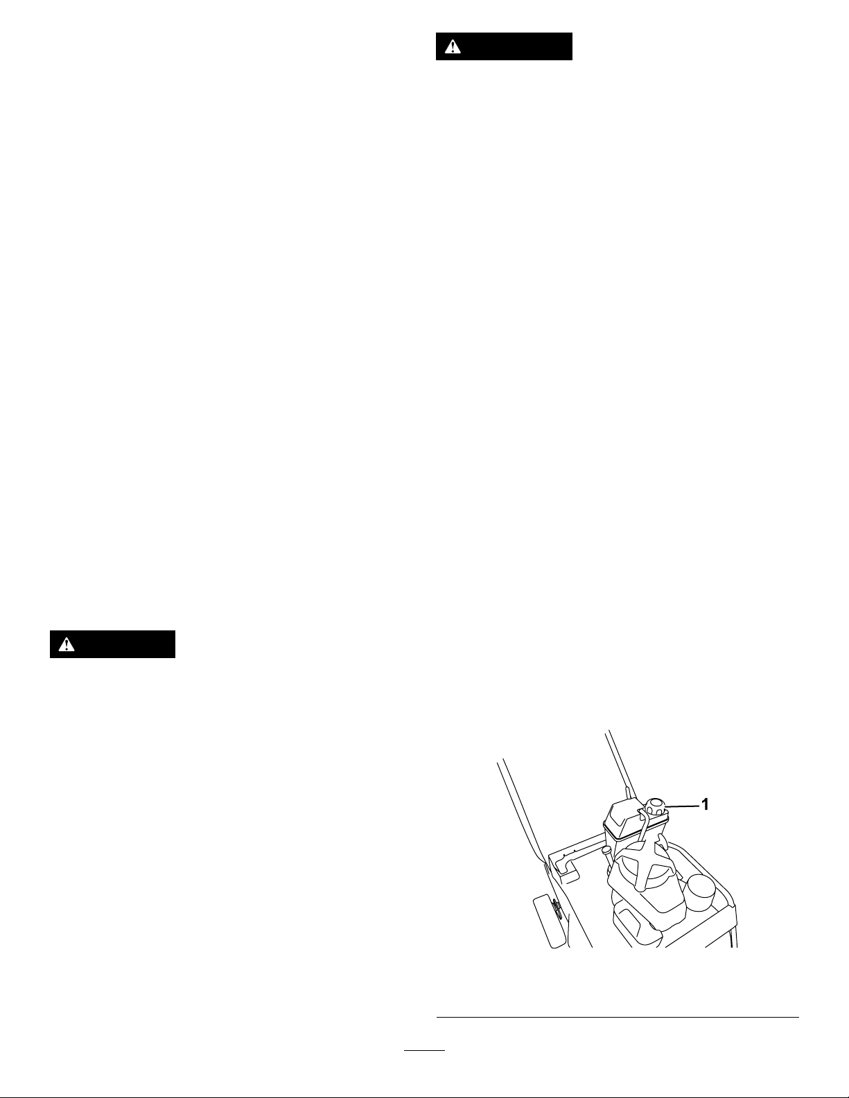
CheckingtheEngine-Oil
1
2
4
6
7
8
3
5
G01991 1
g019653
1
Level
ServiceInterval:Beforeeachuseordaily
1.Movethemachinetoalevelsurface.
2.Removethedipstickbyrotatingthecap
counterclockwiseandpullingitout(Figure14).
Figure14
1.Full3.Low
2.High
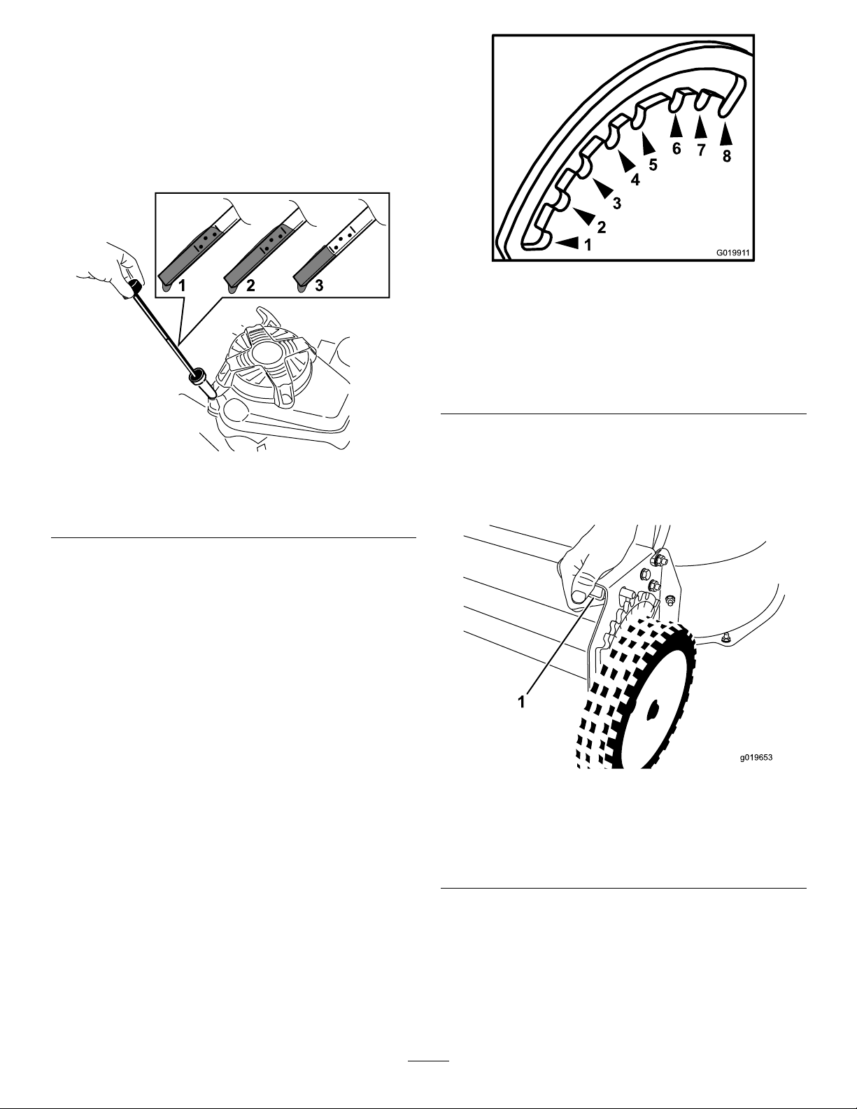
g019911
Figure15
Viewfromfront,leftsideofthemachine
1.38mm(1-1/2inches)5.89mm(3-1/2inches)
2.51mm(2inches)6.102mm(4inches)
3.64mm(2-1/2inches)7.114mm(4-1/2inches)
4.76mm(3inches)8.127mm(5inches)
Thecuttingheightiscontrolledwithafrontleveranda
g194742
rearlever,bothontheleftsideofthemachine(Figure
16andFigure17).Toraiseorlowerthemachine,
engagethelever,raiseorlowerthemachine,and
thendisengagethelever.
3.Wipethedipstickcleanwithacleancloth.
4.Insertthedipstickintotheoil-lltube,then
removethedipstick.
5.Readtheoillevelonthedipstick(Figure14).
•IftheoilisbelowtheAddmarkonthe
dipstick,carefullypourasmallamountofoil
intotheoil-lltube,wait3minutes,andthen
repeatsteps3through5untiltheoillevelis
attheFullmarkonthedipstick.
•IftheoilisabovetheFullmarkonthe
dipstick,draintheexcessoiluntiltheoillevel
isattheFullmarkonthedipstick.Todrain
theexcessoil,refertoChangingtheEngine
Oil(page19).
Important:Iftheoillevelinthecrankcase
istoolowortoohighandyourunthe
engine,youmaydamagetheengine.
6.Installthedipstickintotheoil-lltubesecurely.
AdjustingtheCutting
g019653
Figure16
Frontcuttingheightlever
1.Squeezethelevertodisengageit.
Height
Thecuttingheightsrangefrom38mm(1-1/2inches)
to127mm(5inches)in13mm(1/2inch)increments.
11
Page 13
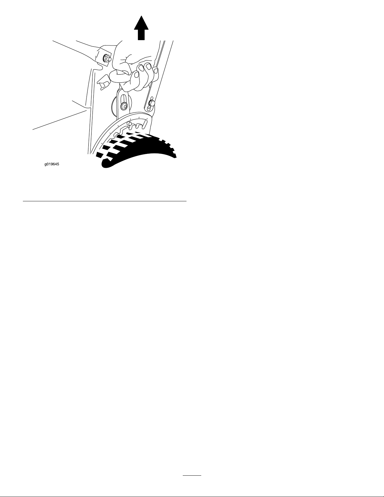
g019645
Figure17
Rearcuttingheightlever
CheckingtheBlade-Stop SystemOperation
Beforeeachuse,checkthatthebladesstopwithin3
secondsofreleasingthecontrolbar.
UsingtheGrassBag
ServiceInterval:Beforeeachuseordaily—Check
theblade-stopsystemoperation.
Thebladesshouldstopwithin3
secondsofreleasingthecontrolbar;
iftheydonot,contactanAuthorized
ServiceDealer.
condition.Havethemachineinspectedand
servicedbyanAuthorizedServiceDealer.
6.Shutofftheengineandwaitforallmovingparts
tostop.
NotUsingtheGrassBag
1.Movethemachineontoapavedsurfaceina
non-windyarea.
2.Setall4wheelstothe3-1/2inch(89mm)cutting
heightsetting.
3.T akeahalfsheetofnewspaperandcrumpleit
intoaballsmallenoughtogounderthemachine
(about3inchesor75mmindiameter).
4.Placethenewspaperballabout5inches(13
cm)infrontofthemachine.
5.Starttheengine.
6.Engagetheblades.
g019645
7.Releasethecontrolbarandbegincountingout
3seconds.
8.Onthecountof3,pushthemachinequickly
forwardoverthenewspaper.
9.Shutofftheengineandwaitforallmovingparts
tostop.
10.Gotothefrontofthemachineandcheckthe
newspaperball.
Note:Ifthenewspaperballdidnotgounder
themachine,repeatsteps4through10.
Important:Ifthenewspaperisunravelledor
shredded,thebladesdidnotstopproperly,
whichcouldresultinanunsafeoperating
condition.ContactanAuthorizedService
Dealer.
DuringOperation
Youcanusethegrassbagtochecktheblade-stop
system.
1.Removetherear-dischargeplug.
2.Installtheemptygrassbagonthemachine.
3.Starttheengine.
4.Engagetheblades.
Note:Thebagshouldbegintoinate,indicating
thatthebladesarerotating.
5.Whilewatchingthebag,releasethecontrolbar.
Note:Ifthebagdoesnotdeatewithin
3secondsofreleasingthecontrolbar,the
blade-stopsystemmaybedeterioratingand,
ifignored,couldresultinanunsafeoperating
DuringOperatingSafety
GeneralSafety
•Wearappropriateclothing,includingeye
protection;slip-resistant,substantialfootwear;and
hearingprotection.Tiebacklonghairanddonot
wearjewelry .
•Donotoperatethemachinewhileill,tired,or
undertheinuenceofalcoholordrugs.
•Thebladeissharp;contactingthebladecanresult
inseriouspersonalinjury.Shutofftheengineand
waitforallmovingpartstostopbeforeleavingthe
operatingposition.
•Whenyoureleasetheblade-controlbar,the
engineshouldshutoffandthebladeshouldstop
12
Page 14
within3seconds.Ifnot,stopusingyourmachine
g019650
1
g019651
1
immediatelyandcontactanAuthorizedService
Dealer.
•Operatethemachineonlyingoodvisibilityand
appropriateweatherconditions.Donotoperate
themachinewhenthereistheriskoflighting.
•Wetgrassorleavescancauseseriousinjuryif
youslipandcontacttheblade.Mowonlyindry
conditions.
•Useextremecarewhenapproachingblind
corners,shrubs,trees,orotherobjectsthatmay
blockyourview.
•Watchforholes,ruts,bumps,rocks,orother
hiddenobjects.Uneventerraincouldcausea
slip-and-fallaccident.
•Stopthemachineandinspectthebladesafter
strikinganobjectorifthereisanabnormal
vibrationinthemachine.Makeallnecessary
repairsbeforeresumingoperation.
•Beforeleavingtheoperatingposition,shutoffthe
engine,removethekey,andwaitforallmoving
partstostop.
•Iftheenginehasbeenrunningthemuferwillbe
hotandcanseverelyburnyou.Keepawayfrom
thehotmufer.
•Checkthegrasscatchercomponentsandthe
dischargeguardfrequentlyandreplacethemwith
themanufacturer’srecommendedpartswhen
necessary.
•Useaccessoriesandattachmentsapprovedby
theTheT oro®Companyonly.
SlopeSafety
•Mowacrossthefaceofslopes;neverupand
down.Useextremecautionwhenchanging
directiononslopes.
g019651
Figure18
1.Fuel-shutoffvalve
3.MovethethrottlecontroltotheCHOKEposition
(Figure1 1).
4.Pullthestarterhandlelightlyuntilyoufeel
resistance,thenpullitsharply.
5.MovethethrottlecontrollevertotheFAST
positionwhentheenginestarts(Figure10).
Note:Iftheenginefailstostartafter3pulls,
repeatsteps3through5.
ShuttingofftheEngine
1.MovethethrottlecontroltotheOFFpositionand
waitforallmovingpartstostop.
2.Closethefuel-shutoffvalveanddisconnectthe
wirefromthesparkplugifyoudonotusethe
machineorleaveitunattended.
OperatingtheSelf-Propel
•Donotmowonexcessivelysteepslopes.Poor
footingcouldcauseaslip-and-fallaccident.
•Donotmowneardrop-offs,ditches,or
embankments.Y oucouldloseyourfootingor
balance.
StartingtheEngine
1.Connectthewiretothesparkplug(Figure9).
2.Openthefuel-shutoffvalve(Figure18).
Note:Whenthefuel-shutoffvalveisopen,the
leverisparallelwiththefuelline.
DriveandEngagingthe
CuttingBlades
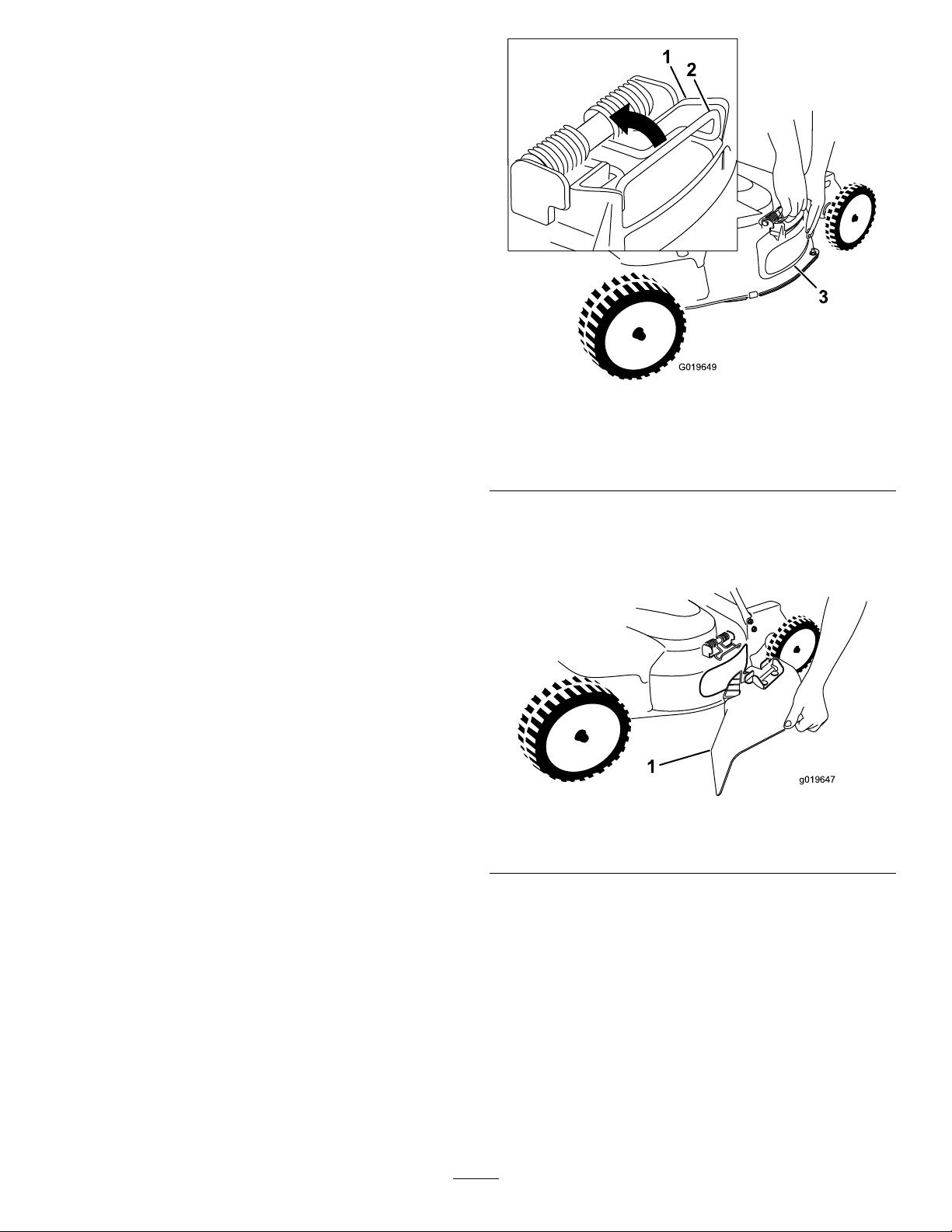
Tooperatetheself-propeldrive,holdthedrivebail
againstthehandle(Figure19).
13
Page 15
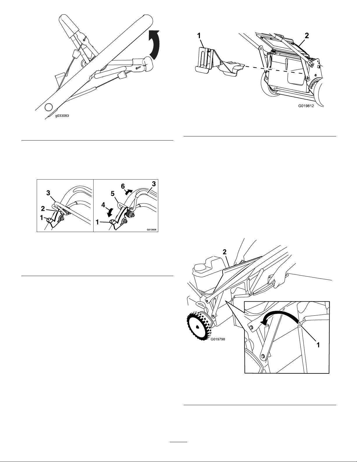
Figure19
G019812
1
G019798
2
intotherear-dischargechuteuntilthelatchlocks
intoplace;refertoFigure21.
g019812
Figure21
g033083
1.Rear-dischargeplug
2.Reardeector
Toengagethecuttingblades,dothefollowing:
1.Pushandholdtheblade-controllocklever
forwardtoreleasetheblade-controlbail(Figure
20).
Figure20
1.Blade-controllocklever4.Push
2.Lockedposition5.Unlockedposition
3.Blade-controlbail
6.Squeezeagainsthandle
2.Squeezetheblade-controlbailagainstthe
handleandreleasetheblade-controllocklever;
thebladeshouldengage.
3.Releasetheblade-controlbailtodisengagethe
blade.Theblade-controllockleverwillresetto
locktheblade-controlbail.
BaggingtheClippings
Usethegrassbagwhenyouwanttocollectgrassand
leafclippingsfromthelawn.
Iftheside-dischargechuteisonthemachine,
removeitandinstalltheside-dischargedeector
beforebaggingtheclippings;refertoInstallingthe
Side-DischargeChute(page15).
InstallingtheGrassBag
g012606
1.Raiseandholdupthereardeector(Figure22).
RecyclingtheClippings
Thismachinecomesfromthefactoryreadytorecycle
grassandleafclippingsbackintothelawn.T oprepare
themachinetorecycle:
•Iftheside-dischargechuteisonthemachine,
removeitandinstalltheside-dischargedeector;
refertoRemovingtheSide-DischargeChute
(page15).
•Ifthegrassbagisonthemachine,removeit;refer
toRemovingtheGrassBag(page15).
•Iftherear-dischargeplugisnotinstalled,gripitby
thehandle,raisethereardeector,andinsertit
Figure22
1.Bagrod
2.Reardeector
2.Removetherear-dischargeplugbypullingdown
onthelatchwithyourthumbandpullingtheplug
outfromthemachine(Figure21).
14
g019798
Page 16
3.Installthebagrodintothenotchesatthebase
G019649
1
2
3
g019647
1
ofthehandle,androckthebagbackandforth
toensurethattherodisseatedatthebottomof
bothnotches;refertoFigure22.
4.Lowerthereardeectoruntilitrestsonthe
grassbag.
RemovingtheGrassBag
Toremovethebag,reversethestepsinInstallingthe
GrassBagabove.
Side-Dischargingthe Clippings
Usethesidedischargeforcuttingverytallgrass.
InstallingtheSide-Discharge
Chute
Important:Ensurethattherear-dischargeplugis
inplacebeforeyourecycletheclippings.
1.Shutofftheengineandwaitforallmovingparts
tostop.
2.Removethegrassbagifitisinstalledonthe
machine;refertoRemovingtheGrassBag
(page15).
3.Inserttherear-dischargeplug;refertoBagging
theClippings(page14).
4.Removetheside-dischargedeectorbypulling
uponthespringthatholdsthedeectorinplace
andremovingthedeector(Figure23).
Figure23
1.T opoftheside-discharge
deector
2.Spring
5.Installtheside-dischargechute(Figure24)by
pullinguponthespring,placingthechuteover
theopening,andloweringthespringoverthe
tabsontopofthedischargechute.
3.Side-dischargedeector
Figure24
g019649
g019647
1.Side-dischargechute
RemovingtheSide-Discharge
Chute
Toremovetheside-dischargechute,reversethesteps
inInstallingtheSide-dischargeChute.
OperatingTips
GeneralTips
•Reviewthesafetyinstructionsandreadthis
manualcarefullybeforeoperatingthemachine.
15
Page 17

•Cleartheareaofsticks,stones,wire,branches,
andotherdebristhatthebladescouldhitand
throw.
•Keepeveryone,especiallychildrenandpets,away
fromtheareaofoperation.
•Avoidstrikingtrees,walls,curbs,orothersolid
objects.Neverdeliberatelymowoveranyobject.
•Ifthemachinestrikesanobjectorstartstovibrate,
immediatelystoptheengine,disconnectthewire
fromthesparkplug,andexaminethemachinefor
damage.
•Maintainsharpbladesthroughoutthecutting
season.Periodicallyledownnicksontheblades.
•Replacethebladeswhennecessarywithoriginal
Tororeplacementblades.
•Mowonlydrygrassorleaves.Wetgrassand
leavestendtoclumpontheyardandcancause
themachinetoplugortheenginetostall.
•Cleanunderthemachineaftereachmowing.
RefertoCleaningundertheMachine(page16).
•Keeptheengineingoodrunningcondition.
•Settheenginespeedtothefastestpositionforthe
bestcuttingresults.
•Cleantheairlterfrequently.Mulchingstirsup
moreclippingsanddustwhichclogstheairlter
andreducesengineperformance.
CuttingGrass
•Grassgrowsatdifferentratesatdifferenttimes
oftheyear.Inthesummerheat,itisbesttocut
grassatthe51mm(2inch),64mm(2-1/2inch),
or83mm(3inch)cutting-heightsettings.Cutonly
aboutathirdofthegrassbladeatatime.Donot
cutbelowthe51mm(2inch)settingunlessthe
grassissparseoritislatefallwhengrassgrowth
beginstoslowdown.
•Whencuttinggrassover15cm(6inches)tall,rst
mowatthehighestcuttingheightsettingandwalk
slower;thenmowagainatalowersettingforthe
bestlawnappearance.Ifthegrassistoolongand
theleavesclumpontopofthelawn,themachine
mayplugandcausetheenginetostall.
•Alternatethemowingdirection.Thishelps
dispersetheclippingsoverthelawnforeven
fertilization.
CuttingLeaves
•Aftercuttingthelawn,ensurethathalfofthelawn
showsthroughthecutleafcover.Y oumayneed
tomakemorethanasinglepassovertheleaves.
•Forlightleafcoverage,setallthewheelsatthe
samecuttingheightsetting.
•Slowdownyourmowingspeedifthemachine
doesnotcuttheleavesnelyenough.
AfterOperation
AfterOperatingSafety
GeneralSafety
•Cleangrassanddebrisfromthemachinetohelp
preventres.Cleanupoilorfuelspills.
•Allowtheenginetocoolbeforestoringthemachine
inanyenclosure.
•Neverstorethemachineorfuelcontainerwhere
thereisanopename,spark,orpilotlight,such
asonawaterheateroronotherappliances.
HaulingSafety
•Usecarewhenloadingorunloadingthemachine.
•Securethemachinefromrolling.
CleaningundertheMachine
Foroptimalcuttingperformance,keeptheunderside
ofthemachineclean.Youmayeitherwashorscrape
theclippingsawayfromunderthemachine.
WashingundertheMachine
ServiceInterval:Beforeeachuseordaily—Clean
underthemachinehousing.
1.Positionthemachineonaatconcreteor
asphaltsurfacenearagardenhose.
2.Starttheengine.
3.Holdtherunninggardenhoseathandlelevel
anddirectthewatertoowonthegroundjustin
frontoftherightreartire(Figure25).
Ifthenishedlawnappearanceisunsatisfactory,try1
ormoreofthefollowing:
•Sharpentheblades.
•Walkataslowerpacewhilemowing.
•Raisethecuttingheightonyourmachine.
•Cutthegrassmorefrequently.
•Overlapcuttingswathsinsteadofcuttingafull
swathwitheachpass.
g002275
Figure25
1.Rightrearwheel
16
Page 18
Note:Thebladeswilldrawinwaterandwash
outclippings.Letthewaterrununtilyouno
longerseeclippingsbeingwashedoutfrom
underthehousing.
4.Shutofftheengineandwaitforallmovingparts
tostop.
5.Turnoffthewater.
6.Startthemachineandletitrunforafewminutes
todryoutthemoistureonthemachineandits
components.
ScrapingundertheMachine
Ifwashingdoesnotremovealldebrisfromunderthe
machine,scrapeitclean.
1.Disconnectthewirefromthesparkplug.
2.Drainthefuelfromthefueltank;referto
EmptyingtheFuelTankandCleaningtheFilter
(page21).
3.Tipthemachineontoitsside,withtheairlter
upintheair,untiltheupperhandlerestsonthe
ground.
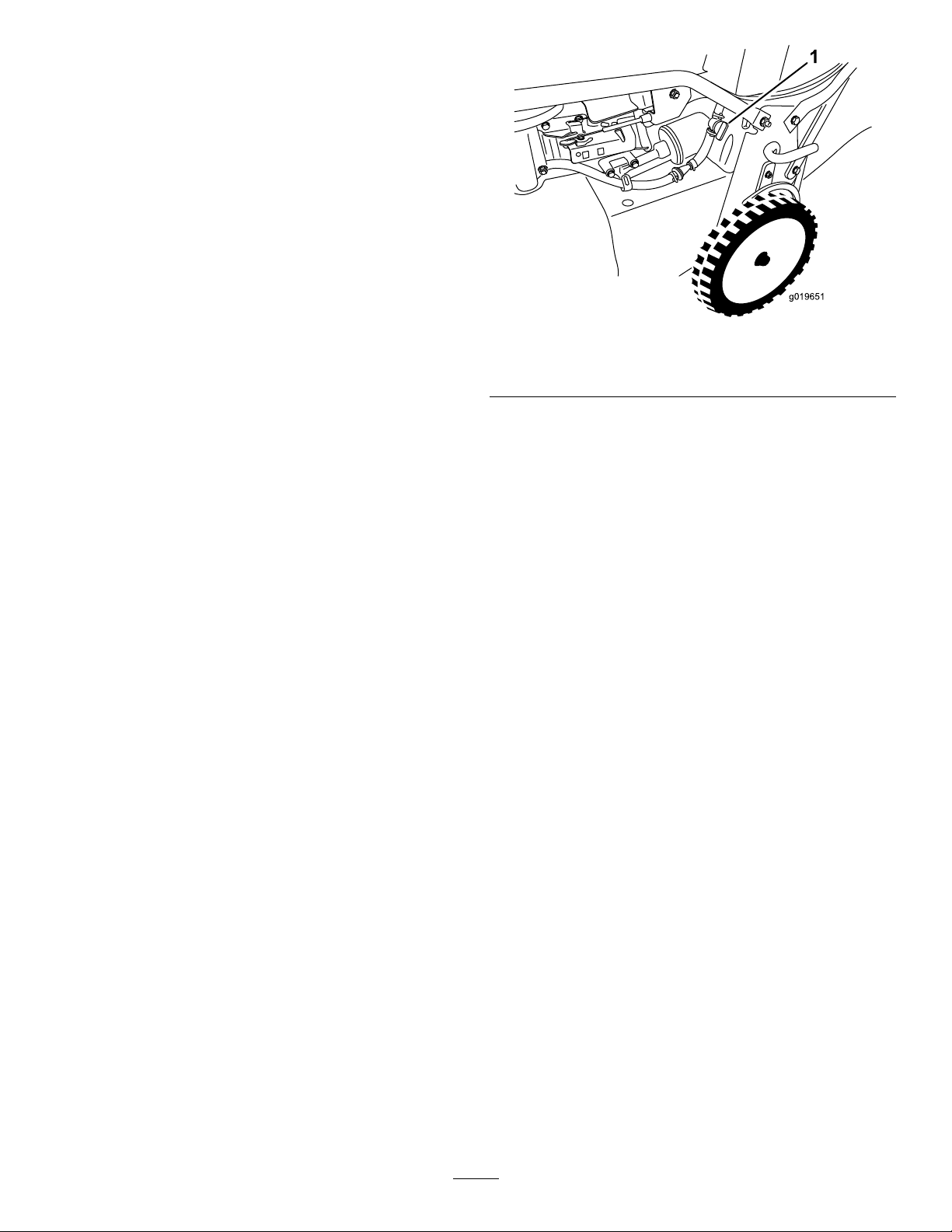
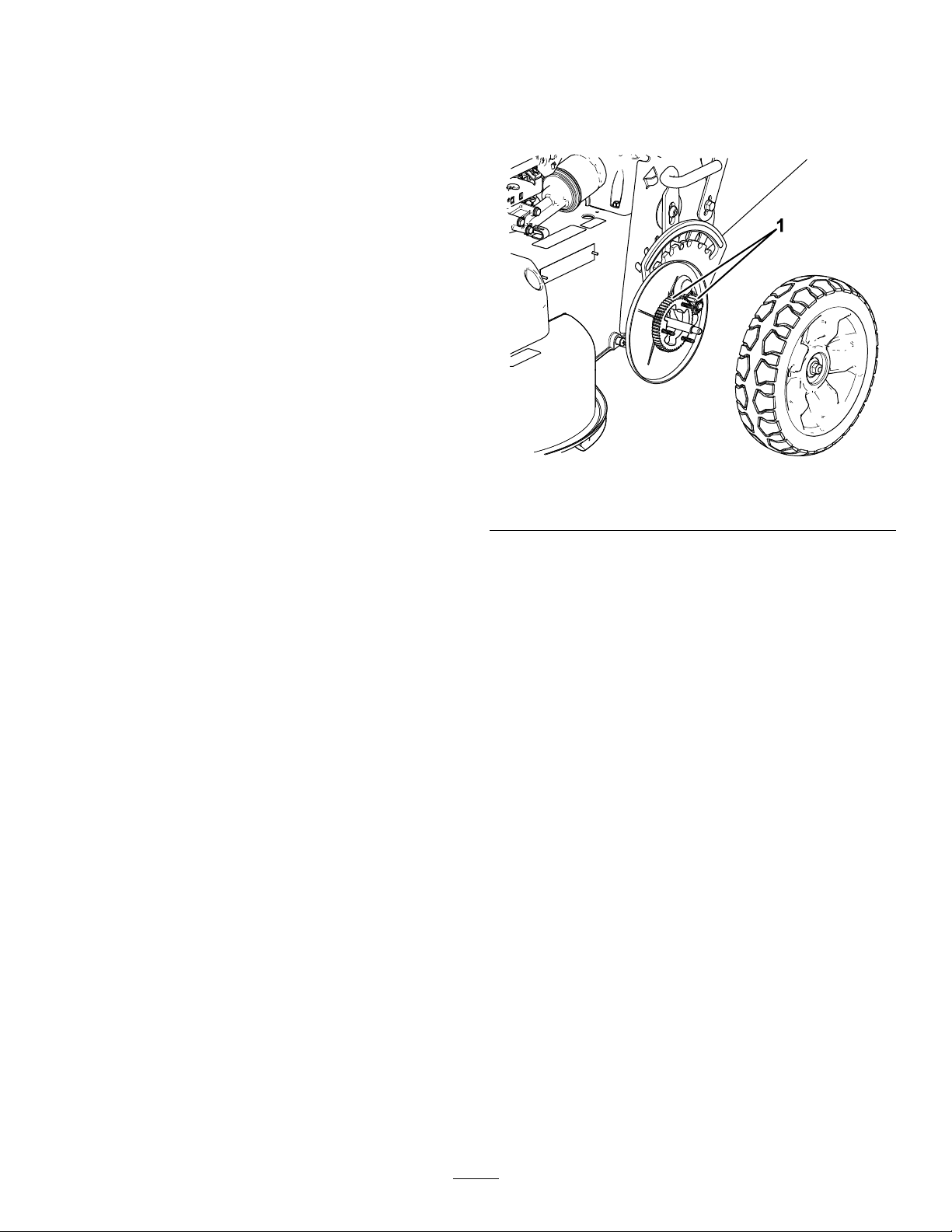
CleaningtheWheels
ServiceInterval:Every40hours
1.Removetherearwheelsandcleananydebris
fromthewheel-geararea.
g196471
Figure26
1.Gears
4.Removethedirtandgrassclippingswitha
hardwoodscraper;avoidburrsandsharpedges.
5.Turnthemachineupright.
6.Fillthefueltank.
7.Connectthewiretothesparkplug.
2.Aftercleaning,applyasmallamountof
anti-seizetothegears.
Note:Ifyouareoperatingthemachineinextreme
conditions,cleaningthewheelsmorefrequentlythan
recommendedwillresultinincreasedgearlife.
Note:Topreventdamagetothebearingseals,donot
useahighpressurewatersprayeronthebearings.
17
Page 19

Maintenance
Note:Determinetheleftandrightsidesofthemachinefromthenormaloperatingposition.
ReplacementpartsareavailablefromanAuthorizedServiceDealeroratwww.torodealer.com(UScustomers
only).EnginepartsareavailableonlyfromanAuthorizedServiceDealer.
RecommendedMaintenanceSchedule(s)
MaintenanceService
Interval
Aftertherst5hours
Beforeeachuseordaily
Every25hours
Every40hours
Every50hours
Every100hours
MaintenanceProcedure
•Changetheengineoilwithouttheoillter.
•Servicetheblade-drivesystem.
•Checktheengine-oillevel.
•Checktheblade-stopsystemoperation.Thebladesshouldstopwithin3secondsof
releasingthecontrolbar;iftheydonot,contactanAuthorizedServiceDealer.
•Cleanunderthemachinehousing.
•Inspecttheairlter.
•Checkthecuttingbladesandservicethem,ifnecessary .
•Inspecttheblades.
•Cleanthefoampre-cleaner(morefrequentlyindustyconditions).
•Cleanthewheelsandgears.
•Changetheengineoil(moreoftenindustyconditions).
•Checktheconditionofthebelts.
•Checkthefuelhoseandreplaceitifnecessary.
•Removedebrisfromunderthebeltcover.
•Servicetheblade-drivesystem.
•Changetheoillter.
•Checkthesparkplug.
•Cleanthefueltanklter.
•Changethefuellter.
Every250hours
Every300hours
Yearlyorbeforestorage
•Changetheblade-brake-clutchbelt.
•Changethetransmissionbelt.
•Replacethepaperairlter(morefrequentlyindustyconditions).
•Emptythefueltankbeforerepairsasdirectororbeforestorage.
Important:Refertoyourenginemanualforadditionalmaintenanceprocedures.
MaintenanceSafety
•Disconnectthespark-plugwirefromthesparkplugbeforeperforminganymaintenanceprocedure.
•Wearglovesandeyeprotectionwhenservicingthemachine.
•Thebladeissharp;contactingthebladecanresultinseriouspersonalinjury.Weargloveswhenservicing
theblade.
•Nevertamperwithsafetydevices.Checktheirproperoperationregularly.
•Tippingthemachinemaycausethefueltoleak.Fuelisammableandexplosive,andcancausepersonal
injury.Runtheenginedrytoremovethefuelwithahandpump;neversiphonthefuel.
18
Page 20
ServicingtheAirFilter
ChangingtheEngineOil
ServiceInterval:Beforeeachuseordaily
Every25hours—Cleanthefoampre-cleaner
(morefrequentlyindustyconditions).
Every300hours—Replacethepaperairlter
(morefrequentlyindustyconditions).
Important:Donotoperatetheenginewithout
theairlterassembly;extremeenginedamage
willoccur.
1.Shutofftheengineandwaitforallmovingparts
tostop.
2.Disconnectthewirefromthesparkplug.
3.Removethecoverandcleanitthoroughly
(Figure27).
ServiceInterval:Aftertherst5hours—Changethe
engineoilwithouttheoillter.
Every50hours—Changetheengineoil(more
oftenindustyconditions).
Note:Runtheengineafewminutesbeforechanging
theoiltowarmit.Warmoilowsbetterandcarries
morecontaminants.
Engineoilcapacity:Withoillter:0.85L(29oz);
withoutoillter:0.65L(22oz)
Oilviscosity:SAE30orSAE10W-30detergentoil
APIserviceclassication:SJorhigher
1.Movethemachinetoalevelsurface.
2.RefertoMaintenanceSafety(page18).
3.Removethedipstickbyrotatingthecap
counterclockwiseandpullingitout(Figure28).
g006591
Figure27
1.Cover3.Air-lterbase
2.Foampre-lterandpaper
lter
4.Removethefoampre-lterandpaperlter
(Figure27).
5.Removethefoampre-lterfromthepaperlter
(Figure27),andreplacethepaperlterifitis
excessivelydirty.
Important:Donottrytocleanapaperlter.
6.Washthefoampre-cleanerwithamilddetergent
andwater,thenblotitdry.
Note:Donotaddoiltothefoampre-cleaner.
7.Installthefoampre-cleanerontothepaperlter.
8.Installtheair-lterassembly.
9.Installthecover.
g194742
Figure28
1.Full3.Low
2.High
4.Tipthemachineontoitsside(sothattheair
lterisup)todraintheusedoilfromtheoil-ll
tube(Figure29).
19
Page 21
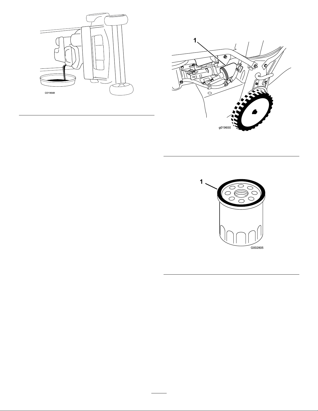
G019648
Figure29
g019650
1
5.Afterdrainingtheusedoil,returnthemachineto
theoperatingposition.
6.Carefullypourabout3/4oftheenginecapacity
ofoilintotheoil-lltube.
7.Waitabout3minutesfortheoiltosettleinthe
engine.
8.Wipethedipstickcleanwithacleancloth.
9.Insertthedipstickintotheoil-lltube,then
removethedipstick.
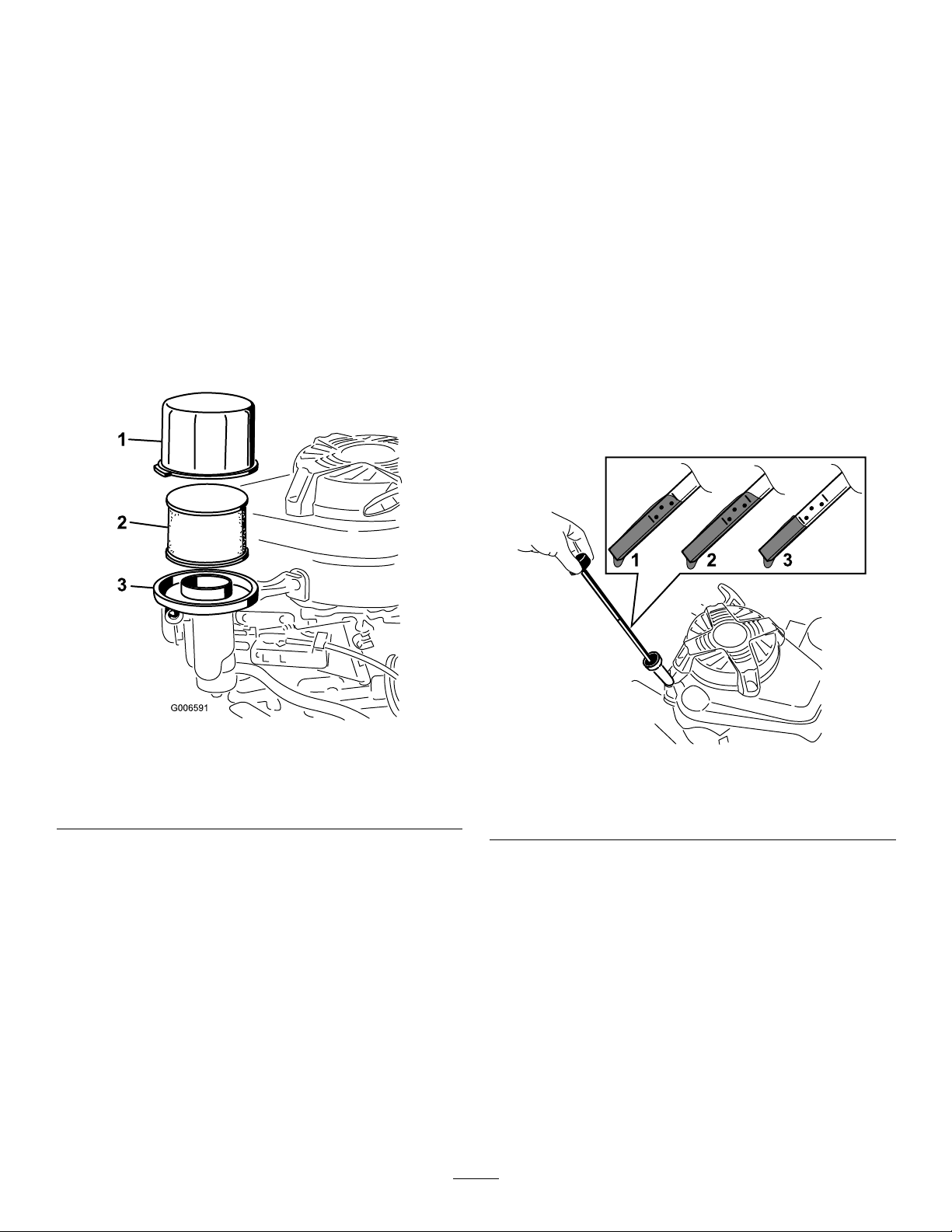
6.Removetheoillter(Figure30).
Note:Makesurethattheoil-ltergasketcomes
offwiththelter.
g019648
g019650
Figure30
1.Oillter
7.Useyourngertocoatthegasketonthenew
lterwithoil(Figure31).
10.Readtheoillevelonthedipstick(Figure28).
•IftheoillevelisbelowtheAddmarkonthe
dipstick,carefullypourasmallamountof
oilintotheoil-lltube,wait3minutes,and
repeatsteps8through10untiltheoillevelis
attheFullmarkonthedipstick.
•IftheoillevelisabovetheFullmarkonthe
dipstick,draintheexcessoiluntiltheoillevel
isattheFullmarkonthedipstick.
Important:Iftheoillevelintheengineistoo
lowortoohighandyouruntheengine,you
maydamagetheengine.
11.Installthedipsticksecurely .
12.Recycletheusedoilproperly .
ChangingtheOilFilter
ServiceInterval:Every100hours
1.Runtheenginetowarmtheoil.
2.Shutofftheengineandwaitforallmovingparts
tostop.
3.Disconnectthewirefromthesparkplug.
4.Draintheengineoil;refertoChangingthe
EngineOil(page19).
5.Placearagundertheoilltertocatchanyoil
thatmayleakoutasyouremovethelter.
g002805
Figure31
1.Gasket
8.Installthenewlteruntilthegasketcontacts
thelterbase,thenhandtightenthelteran
additional2/3turn.
9.FillthecrankcasetotheFulllineonthedipstick
withfreshoil;refertoChangingtheEngineOil
(page19).
10.Connectthewiretothesparkplug.
11.Runtheengineforabout3minutes.
12.Shutofftheengine,waitforallmovingpartsto
stop,andcheckforoilleakagearoundthelter.
13.Addoiltocompensatefortheoilintheoillter;
refertoChangingtheEngineOil(page19)
14.Recycletheusedoillteraccordingtolocal
codes.
20
Page 22
ServicingtheSparkPlug
EmptyingtheFuelTankand
ServiceInterval:Every100hours
UseanNGKBPR5ESsparkplugorequivalent.
1.Shutofftheengineandwaitforallmovingparts
tostop.
2.Disconnectthewirefromthesparkplug.
3.Cleanaroundthesparkplug.
4.Removethesparkplugfromthecylinderhead.
Important:Replaceacracked,fouled,or
dirtysparkplug.Donotcleantheelectrodes
becausegritenteringthecylindercan
damagetheengine.
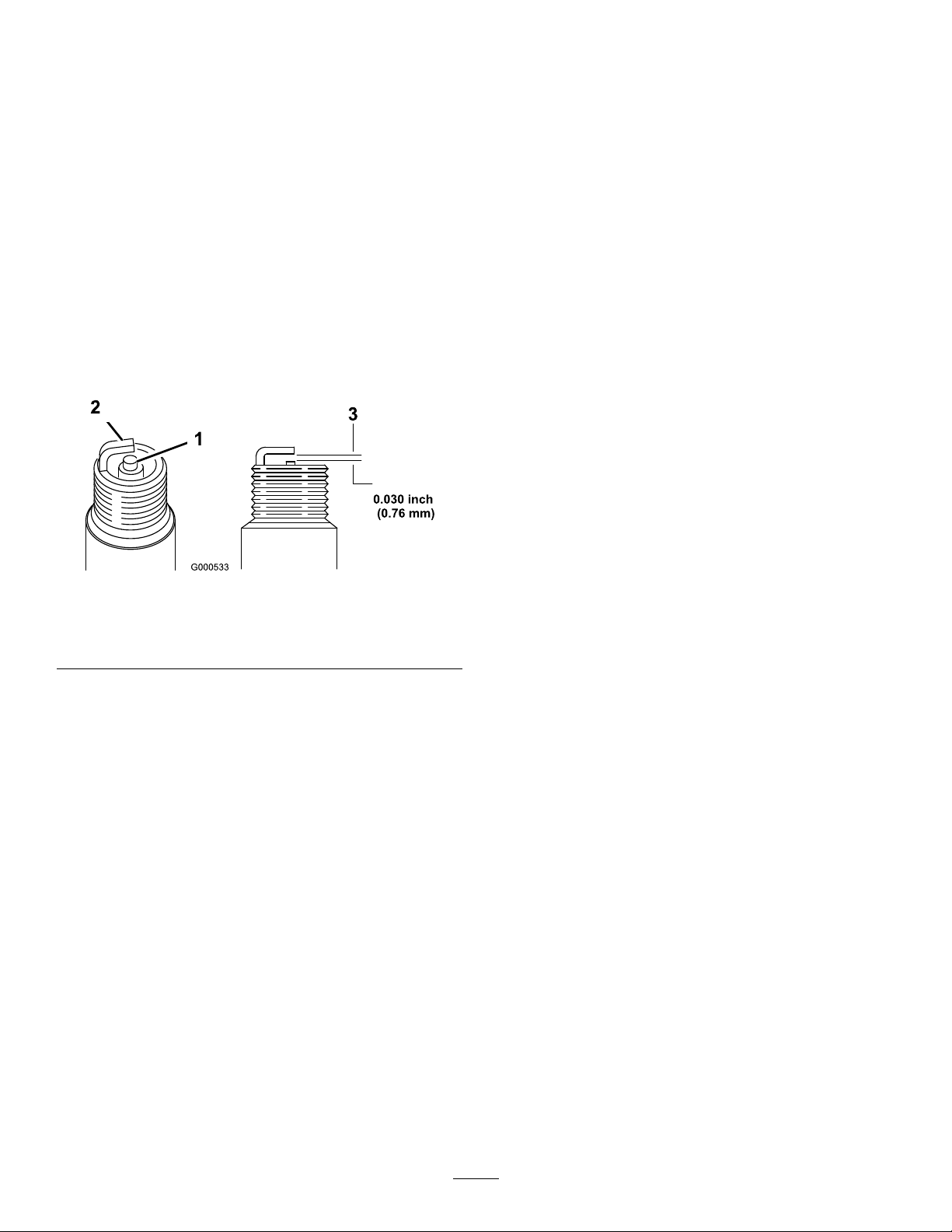
5.Setthegapontheplugto0.76mm(0.030inch);
refertoFigure32.
CleaningtheFilter
ServiceInterval:Every50hours—Checkthefuel
hoseandreplaceitifnecessary.
Every100hours—Cleanthefueltanklter.
Yearlyorbeforestorage—Emptythefueltank
beforerepairsasdirectororbeforestorage.
Note:Thefueltanklter(screen)elementislocated
insidethefueltankattheoutlet.Thislterisapartof
thefueltankandcannotberemoved.
1.Shutofftheengineandwaitforittocooldown.
Important:Drainfuelfromacoldengine
only.
2.Disconnectthewirefromthesparkplug.
3.Closethefuel-shutoffvalve.
4.Disconnectthefuellinebylooseningthetube
clampatthecarburetor.
5.Openthefuel-shutoffvalveanddrainthefuel
completelyfromthetankandfuellineintoan
approvedfuelcontainer.
Figure32
1.Center-electrodeinsulator3.Airgap(nottoscale)
2.Sideelectrode
6.Installthesparkplugandthegasketseal.
7.T orquetheplugto23N∙m(17ft-lb).
8.Connectthewiretothesparkplug.
CheckingtheConditionof theBelts
ServiceInterval:Every50hours
1.Shutofftheengineandwaitforallmovingparts
tostop.
2.Removethebeltcover(Figure9)byremoving
the4boltsthatholdittothemachinehousing.
3.Checkthebeltsforanycracks,frayededges,
burnmarks,oranyotherdamage.
6.Removethefueltankfromthemachine.
g000533
7.Pourasmallamountoffuelinthefueltank,
movethefuelaroundinthetank,andpouritout
intoanapprovedfuelcontainer.
8.Installthefueltankandthefuelline.
ChangingtheFuelFilter
ServiceInterval:Every100hours
1.Shutofftheengineandwaitforallmovingparts
tostop.
2.Disconnectthewirefromthesparkplug.
3.Closethefuel-shutoffvalve(Figure33).
4.Replacealldamagedbelts.
5.Ifyoureplacetheblade-drivebelt,youmust
adjustit.RefertoServicingtheBlade-Drive
System(page22).
6.Installthebeltcoverwiththe4boltsthatyou
removedinstep2.
21
Page 23
g019650
1
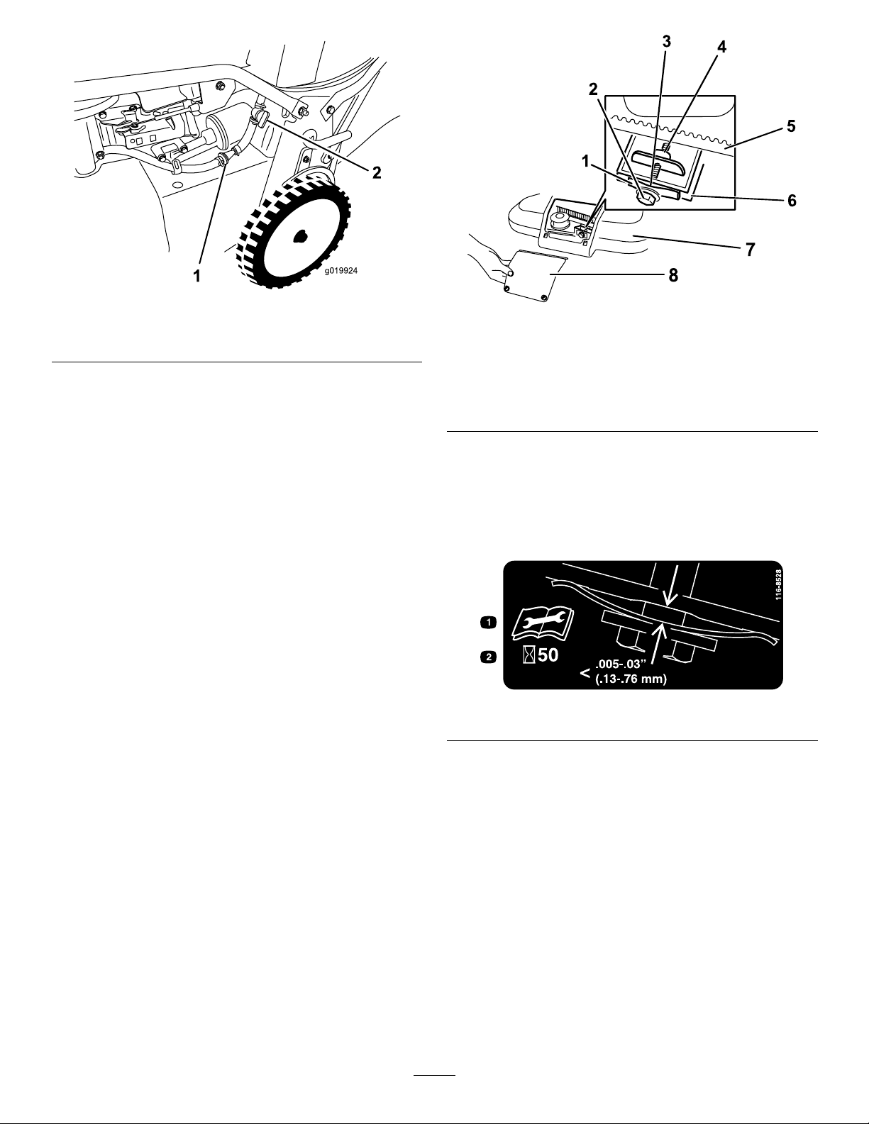
g019924
1
2
Figure33
1.Fuellter2.Fuel-shutoffvalve
4.Removethefuellter(Figure33)fromthefuel
linebylooseningthetubeclampssurrounding
thefuellter.
g019924
Figure34
1.Belt-tensionspring5.Blade-drivebelt
2.Adjustingbolt6.Wall
3.Gap
4.Adjustingnut8.Belt-cover-accesspanel
7.Beltcover
g208925
5.Installanewfuellterinthefuellineusingthe
tubeclampsthatyouremovedinstep4.
ServicingtheBlade-Drive System
ServiceInterval:Aftertherst5hours
Every50hours—Removedebrisfromunder
thebeltcover.
Every50hours—Servicetheblade-drive
system.
1.Loosenthe2screwsonthebelt-cover-access
panelandremovethepanel(Figure34).
2.Brushorblowoutdebrisfromtheinsideofthe
beltcoverandaroundalltheparts.
3.Holdafeelergaugesetbetween0.005and0.03
inches(0.13and0.76mm)againstthewalland
slideitdownbehindthebelttensionspring;refer
toFigure35.
decal116-8528
Figure35
Note:Ifthereisavisiblegapbetweenthe
gaugeandthespring,tightentheadjustingbolt
andthenutuntilthefeelergaugebarelyslides
freelyinandoutofthegap(Figure34).
Important:Donotovertightentheadjusting
bolt.Thiscoulddamagetheblade-drivebelt.
4.Installthebelt-cover-accesspanel.
ServicingtheCutting Blades
ServiceInterval:Beforeeachuseordaily
Important:Youwillneedatorquewrenchto
installthebladesproperly.Ifyoudonothavea
22
Page 24
torquewrenchorareuncomfortableperforming
g017223
thisprocedure,contactanAuthorizedService
Dealer.
Examinethebladesforsharpnessandanywear
ordamagewheneveryourunoutoffuel;referto
InspectingtheBlades(page23).Ifthebladeedgeis
dullornicked,haveitsharpenedorreplaceit.Ifthe
bladesareworn,bent,damagedorcracked,replace
themimmediatelywithgenuineT ororeplacement
blades.
DANGER
Awornordamagedbladecanbreak,anda
pieceofthebladecouldbethrowntowardthe
operatororabystander,resultinginserious
personalinjuryordeath.
•Inspectthebladesperiodicallyforwearor
damage.
•Replacewornordamagedblades.
Note:Maintainsharpbladesthroughoutthecutting
season,becausesharpbladescutcleanlywithout
tearingorshreddingthegrassblades.Tearingand
shreddingturnsgrassbrownattheedges,which
slowsgrowthandincreasesthechanceofdisease.
PreparingtoServicetheCutting
Blades
Tipthemachineontoitsside,withtheairlterupin
theair,untiltheupperhandlerestsontheground.
WARNING
g017223
Figure36
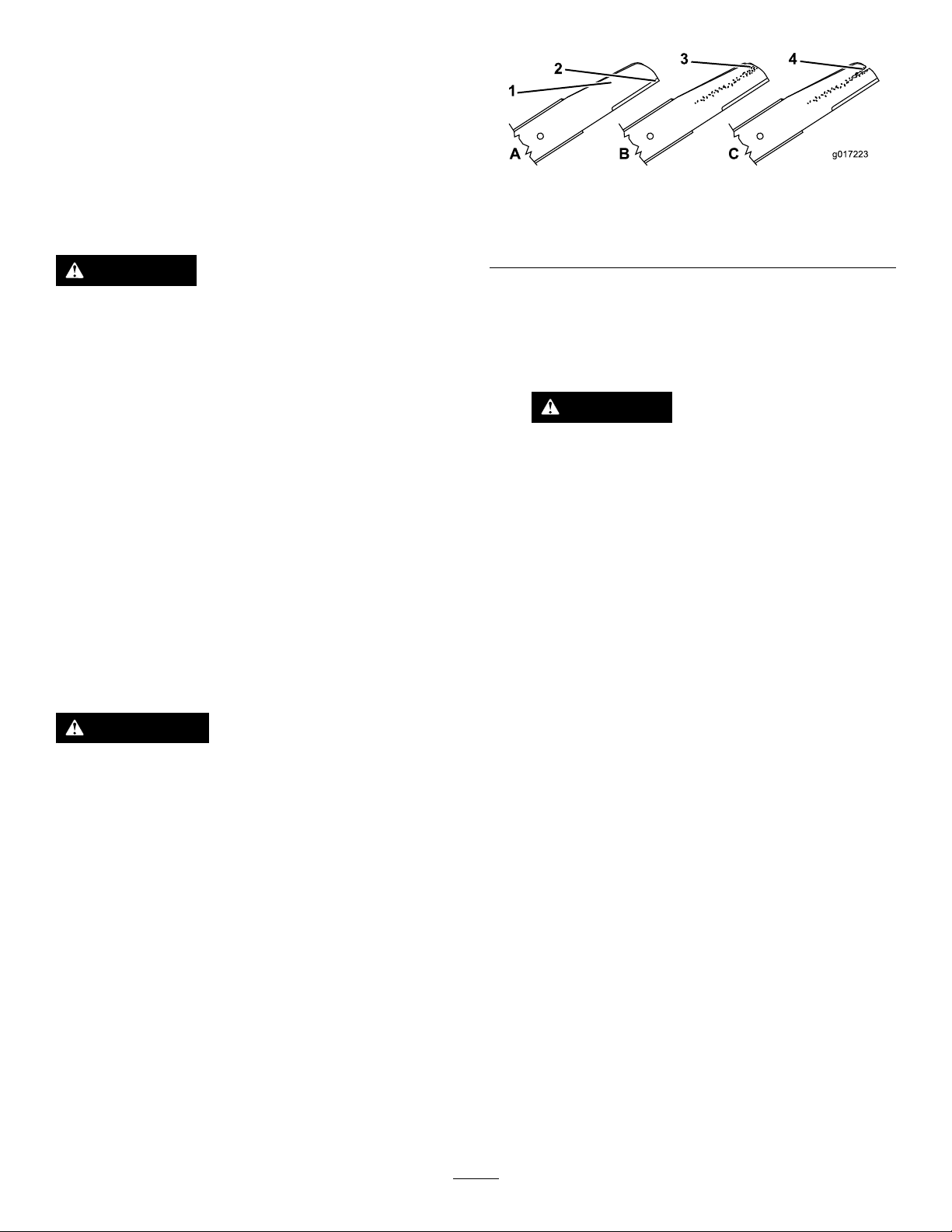
1.Curvedarea3.Wear/slotforming
2.Cuttingedge4.Crack
2.Inspectthebladesthemselves,especiallythe
curvedarea(Figure42).Ifyounoticeany
damage,wear,oraslotforminginthisarea
(Figure36),immediatelyreplacethemwithnew
blades.
DANGER
Ifyouallowabladetowear,aslotwill
formbetweenthesailandatpartofthe
blade.Eventuallyapieceoftheblade
maybreakoffandbethrownfromunder
thehousing,possiblyresultinginserious
injurytoyouorbystanders.
•Inspectthebladesperiodicallyfor
wearordamage.
•Nevertrytostraightenabladethat
isbentorweldabrokenorcracked
blade.
•Checkforbentblades;referto
CheckingforBentBlades(page23).
Thebladesaresharp;contactingablade
couldresultinseriouspersonalinjury.
•Disconnectthewirefromthesparkplug.
•Weargloveswhenservicingtheblades.
InspectingtheBlades
ServiceInterval:Beforeeachuseordaily
1.Inspectthecuttingedges(Figure36).Ifthe
edgesarenotsharporhavenicks,removethe
bladesandhavethemsharpenedorreplace
them.
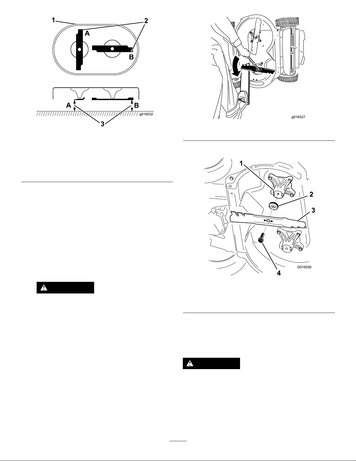
CheckingforBentBlades
1.Rotatethebladesuntiltheyarepositionedas
showninFigure37.
23
Page 25
B
B
2
1
3
g016532
Figure37
G016530
1
2
3
4
g016527
g016532
Figure38
1.Frontofcuttingdeck3.Measurefromthecutting
edgetoasmooth,level
surface
2.MeasureatlocationsA
andB
2.Measurefromalevelsurfacetothecutting
edgesatlocationsAandB,(Figure37),and
recordbothdimensions.
3.Rotatethebladessothattheiroppositeends
areatlocationsAandB.
4.Repeatthemeasurementsinstep2andrecord
them.
Note:IfthedifferencebetweendimensionsA
andBobtainedinsteps2and4exceeds1/8
inch,replacetheblades;refertoRemovingthe
Blades(page24).
WARNING
Abladethatisbentordamagedcould
breakapartandcouldseriouslyinjureor
killyouorbystanders.
•Alwaysreplaceabentordamaged
bladewithanewblade.
2.RemoveeachbladeasshowninFigure39.
g016530
Figure39
1.Spindle(2)3.Blade(2)
2.Bladedriver(2)4.Bladebolt(2)
3.Inspectthepinsonthebladedriversforwear
anddamage.
•Neverleorcreatesharpnotchesin
theedgesorsurfacesofablade.
RemovingtheBlades
Replacethebladeswhentheystrikeasolidobject,
areoutofbalance,bent,orworn.Useonlygenuine
Tororeplacementblades.
1.Useablockofwoodtoholdeachbladesteady
andturnthebladeboltcounterclockwiseas
showninFigure38.
InstallingtheBlades
WARNING
Incorrectlyinstallingthebladescoulddamage
themachineorcauseaninjurytotheoperator
ortobystanders.
Installthebladesaccordingtothe
instructions.
24
Page 26

1.Installtherstbladesothatitishorizontal,along
g016537
1
G016536
withallmountinghardwareasshowninFigure
39.
Note:Tightentheboltwithyourngers.
Important:Positionthecurvedendsofthe
bladestopointtowardthemachinehousing.
Besuretonesttheraisedareasoneach
bladedriverwiththerecessesintheheadof
itscorrespondingspindle,andthepinson
theothersideofeachbladedriverwiththe
holesinitscorrespondingblade.
2.Steadyeachbladewithaboardandturnthe
bladeboltclockwisewithatorquewrenchas
showninFigure40;torqueeachbladeboltto
82N∙m(60ft-lb).
g016536
Figure41
1.Blade(2)
4.Tightenthesecondblade;refertostep2.
5.Rotatethebladesbyhandafull360°turnto
ensurethattheydonottouch.
Note:Ifthebladestoucheachother,theyare
notmountedcorrectly.Repeatsteps1through3
untilthebladesnolongertoucheachother.
ChangingtheBlade-Drive
Figure40
Important:Abolttorquedto82N∙m(60
ft-lb)isverytight.Putyourweightbehind
thewrenchandtightentheboltsecurely .
Thisboltisverydifculttoovertighten.
3.Rotatetheinstalledblade1/4turnuntilitis
vertical,andinstalltheotherbladeinthesame
mannerastherst(refertostep1).
Note:Thebladesshouldbeperpendicular,
forminganinverted“T”asshowninFigure41.
Belt
Changetheblade-drivebeltasneeded.
1.Shutofftheengineandwaitforallmovingparts
tostop.
2.Disconnectthewirefromthesparkplug.
3.Removethebeltcover(Figure9)byremoving
the4boltsthatholdittothemachinehousing.
Note:Savetheboltsforinstallingthebeltcover
tothemachinehousing.
g016537
4.Removeanydebrisfromunderthebeltcover.
5.RemovetheBBCbeltguardandthemounting
hardware.
Note:SavetheBBCbeltguardandhardware
forinstallationlater.
25
Page 27

Figure42
1.BBCbelt2.BBCbeltguard
6.RemovetheBBCbeltfromthefront,leftpulley.
7.Loosentheadjustingbolt(Figure34).
8.Removethexedidlerpulleyandthehardware
(Figure43).
11.Whenyouhavelockedthesprocketsinplace,
installtheblade-drivebeltandthexedidler
pulley.
Note:Ensurethattheteethareengagedinthe
sprockets.
12.Tightenthebelttensiontotherecommended
settings;refertoServicingtheBlade-Drive
System(page22).
13.Removetherodorscrewdriverfromthe
sprockets.
14.Ensurethatthebladesunderthehousingare
properlyaligned;refertoServicingtheCutting
g208922
Blades(page22).
15.InstalltheBBCbeltandtheBBCbeltguardand
hardware.
16.Installthebeltcoverusingthe4boltsthatyou
removedinstep3.
17.Connectthewiretothesparkplug.
18.Checktheoperationofthecontrolbarandthe
blade-brakeclutch.
Note:Savetheidlerpulleyandhardwarefor
installationlater.
Figure43
TheBBCidlerpulleyisremovedforclarity
1.Holeinthehousing3.Fixed-idlerpulley
2.Rightsprockethole
4.Leftsprockethole
Changingthe Blade-Brake-Clutch(BBC) Belt
ServiceInterval:Every250hours
1.Shutofftheengineandwaitforallmovingparts
tostop.
2.Disconnectthewirefromthesparkplug.
3.Removethe4boltsthatholdthebeltcoverto
themachinehousing.
Note:Savetheboltsforinstallingthebeltcover
tothemachinehousing.
4.Removethebeltcover.
5.Removeanydebrisfromunderthebeltcover.
g208924
6.Removethetransmissionbelt;refertoChanging
theTransmissionBelt(page28).
7.RemovetheBBCbeltguard(Figure44).
Note:Savethemountinghardwareforinstalling
theBBCbeltguardlater.
9.Removetheblade-drivebelt.
10.Aligntheholesintherightandleftsprocketswith
theholesinthehousingasshowninFigure43.
Note:Holdthesprocketsinplacewitharod
orascrewdriver.
26
Page 28
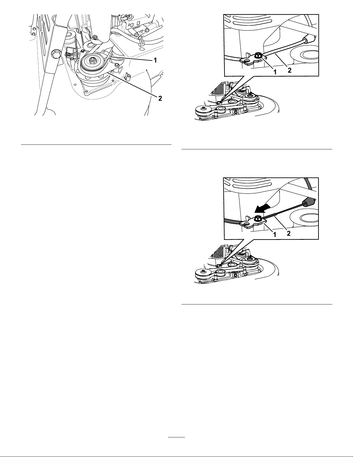
Figure44
1.BBCbelt2.BBCbeltguard
g208922
Figure45
1.Cable-clampscrew
2.Blade-brakecable
g208921
8.RemovetheBBCbeltfromthebrake-drum
pulleyandthenremovethebeltfromthe
machine.
Note:Holdoneofthebladesusingagloveor
aragandturnthebladespindletohelpremove
theBBCbelt.
9.T oinstallanewBBCbelt,reversethesteps
above.
10.AdjusttheBBCcable;refertoAdjustingthe
Blade-BrakeCable(page27).
AdjustingtheBlade-Brake Cable
Adjusttheblade-brakecablewheneveryouinstalla
newcableorreplacetheBBCbelt.
1.Shutofftheengineandwaitforallmovingparts
tostop.
2.Disconnectthewirefromthesparkplug.
3.Removethebeltcover(Figure9)byremoving
the4boltsthatholdittothemachinehousing.
6.Pullthecablejackettoremoveslack(Figure46).
Note:Donotputtensiononthespring.
g208926
Figure46
7.Markthebrakecable(Figure47),thenadjust
thejacketuntilthereisapproximately3mm(1/8
inch)ofslack(Figure48).
Note:Savetheboltsforinstallingthebeltcover
tothemachinehousing.
4.Removeanydebrisfromunderthebeltcover.
5.Loosenthecable-clampscrew(Figure45).
27
Page 29
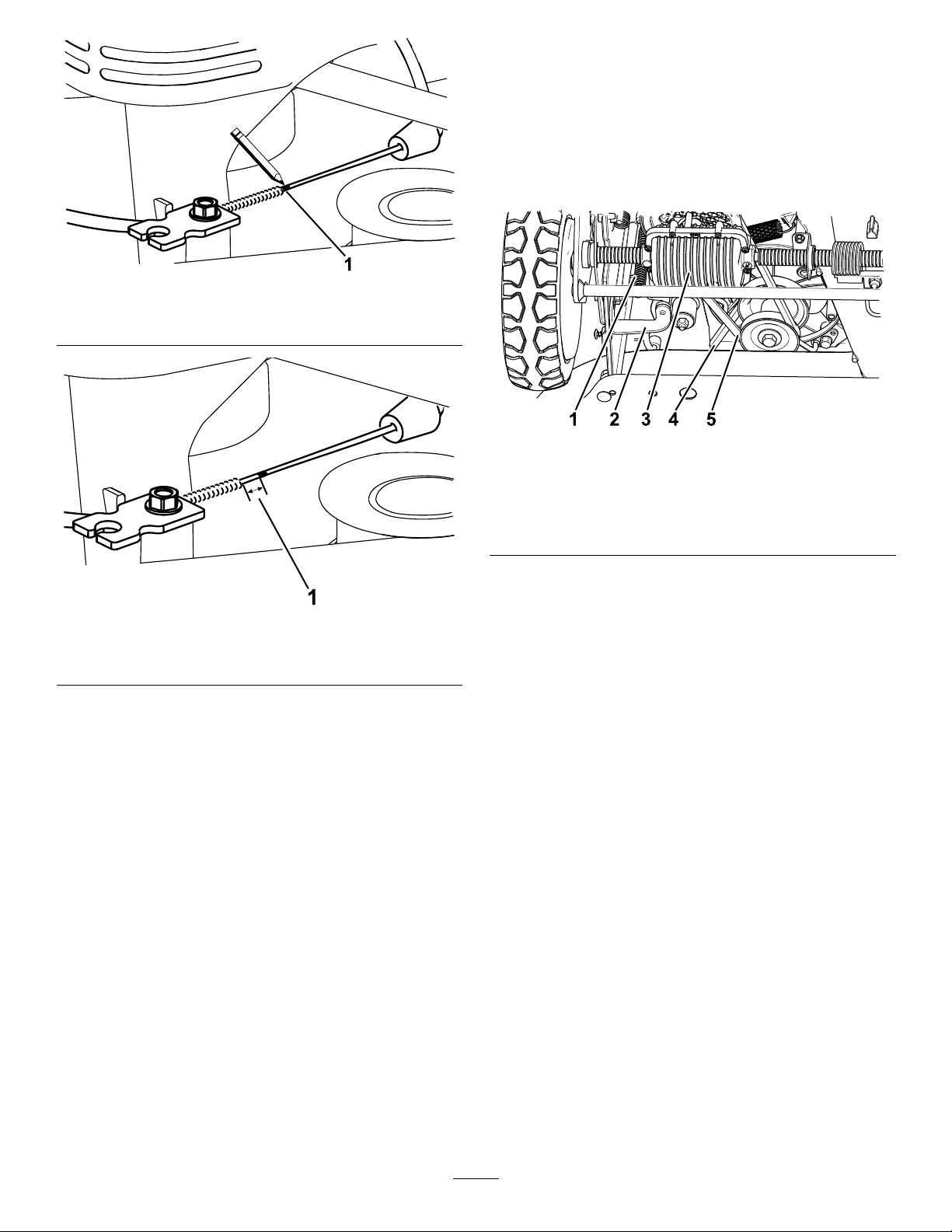
1.Markthecablehere
4.Removethebeltcover.
5.Removeanydebrisfromunderthebeltcover.
6.Loosenthebracketandrotatethebracket
forward(Figure49).
Note:Thebracketpreventsthetransmission
fromtippingtothepointwherethetransmission
beltcomesoff.
g208923
Figure47
g196531
Figure49
Figure48
1.Slack—3mm(1/8inch)
8.T orquethecable-clampscrewto11to14N∙m
(99to121in-lb)tolocktheadjustmentinplace.
9.Installthebeltcoverwiththe4boltsthatyou
removedinstep3.
10.Connectthewiretothesparkplug.
11.Checktheoperationoftheblade-brakeclutch;
refertoServicingtheCuttingBlades(page22).
ChangingtheTransmission Belt
ServiceInterval:Every250hours
1.Shutofftheengineandwaitforallmovingparts
tostop.
2.Disconnectthewirefromthesparkplug.
3.Removethe4boltsthatholdthebeltcoverto
themachinehousing.
Note:Savetheboltsforinstallingthebeltcover
tothemachinehousing.
1.Transmissiontension
spring
2.Bracket5.Transmissionbelt
3.Transmission
4.BBCbelt
7.Removethetransmissiontensionspring.
g208920
8.Removethetransmissionbeltfromthe
transmissionpulley.
9.Removethetransmissionbelt.
10.T oinstallanewtransmissionbelt,reversethe
stepsabove.
AdjustingtheTransmission
Ifthemachinestartstolosetraction,checkandadjust
thetransmission.
1.Shutofftheengineandwaitforallmovingparts
tostop.
2.Disconnectthewirefromthesparkplug.
3.Loosentheboltandnutholdingthebracketinto
place.
4.Adjustthebracketsothatitisincontactwiththe
transmission.
Note:Thebracketpreventsthetransmission
fromtippingtothepointwherethetransmission
beltcomesoff.
5.Tightentheboltandnuttosecurethebracket
intoplace.
28
Page 30
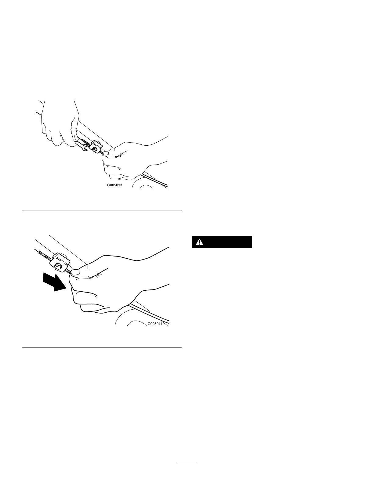
AdjustingtheSelf-Propel Cable
Ifthemachinedoesnotself-propelortendstocreep
forwardwhenyoureleasethecontrolbar,adjustthe
drivecable.
1.Shutofftheengineandwaitforallmovingparts
tostop.
2.Loosenthecablesupportnut(Figure50).
Storage
GeneralInformation
Storethemachineinacool,clean,dryplace.Cover
themachinetokeepitcleanandprotected.
1.Performtherecommendedannualmaintenance
procedures;refertoMaintenance(page18).
2.Cleanunderthemachine;refertoCleaning
undertheMachine(page16).
3.Removechaff,dirt,andgrimefromtheexternal
partsoftheengine,theshrouding,andthetop
ofthemachine.
4.Checktheconditionoftheblades;referto
InspectingtheBlades(page23).
5.Servicetheairlter;refertoServicingtheAir
Filter(page19).
6.Tightenallnuts,bolts,andscrews.
Figure50
3.Pulldownthecablejacket(towardthemower)
untilthereisnoslackinthecable(Figure51).
Figure51
4.Tightenthenutonthecablesupport.
5.Checktheoperationfordesireddrivecontrol.
Note:Iftheunitcreepsforwardwithoutthebail
engagedorifthewheelsspinwhenyoulifttherear
wheelsofftheground,thecableistootight;repeat
steps1and2.
Note:Adjustmenttoobtaindesiredgroundspeedat
fullbailtravelmaybemadeinordertoaccommodate
slowerspeeds.
g005013
g005011
7.T ouchupallrustedorchippedpaintsurfaces
withpaintavailablefromanAuthorizedService
Dealer.
PreparingtheFuelSystem
WARNING
Fuelcanvaporizeifyoustoreitoverlong
periodsoftimeandexplodeifitcomesinto
contactwithanopename.
•Donotstorefueloverlongperiodsoftime.
•Donotstorethemachinewithfuelinthe
fueltankorthecarburetorinanenclosure
withanopename.(Forexample,a
furnaceorawaterheaterpilotlight.)
•Allowtheenginetocoolbeforestoringitin
anyenclosure.
Onthelastrefuelingoftheyear,addfuelstabilizer
tothefuelasdirectedbytheenginemanufacturer.
Emptythefueltankwhenmowingthelasttimebefore
storingthemachine.
1.Runthemachineuntiltheengineshutsofffrom
runningoutoffuel.
2.Starttheengineagain.
3.Allowtheenginetorununtilitshutsoff.
Whenyoucannolongerstarttheengine,itis
sufcientlydry.
29
Page 31

PreparingtheEngine
1.Whiletheengineisstillwarm,changethe
engineoilandtheoillter;refertoChangingthe
EngineOil(page19)andChangingtheOilFilter
(page20).
2.Removethesparkplug.
3.Usinganoilcan,addabout30ml(1oz),of
motoroiltotheenginethroughthespark-plug
hole.
4.Slowlypullthestarterropeseveraltimesto
distributeoilthroughoutthecylinder.
5.Installthesparkplugbutdonotconnectthewire
tothesparkplug.Securethewiresothatitdoes
notcomeintocontactwiththesparkplug.
RemovingtheMachine fromStorage
1.Checkandtightenallfasteners.
2.Removethesparkplugandspintheengine
rapidlyusingthestartertoblowexcessoilfrom
thecylinder.
3.Inspectthesparkplugandreplaceitifitisdirty,
worn,orcracked;refertotheengineowner’s
manual.
4.Installthesparkplugandtightenittothe
recommendedtorqueof20N∙m(180in-lb).
5.Performanyneededmaintenanceprocedures;
refertoMaintenance(page18).
6.Checktheengine-oillevel;refertoCheckingthe
Engine-OilLevel(page11).
7.Fillthefueltankwithfreshfuel;refertoFilling
theFuelT ank(page10).
8.Connectthewiretothesparkplug.
30
Page 32

Troubleshooting
Problem
Theenginedoesnotstart.
Theenginestartshardorlosespower.
PossibleCauseCorrectiveAction
1.Thefueltankisemptyorthefuel
systemcontainsstalefuel.
2.Thefuel-shutoffvalveisclosed.2.Openthefuel-shutoffvalve.
3.Thethrottleleverisnotinthecorrect
position.
4.Thereisdirt,water ,orstalefuelinthe
fuelsystem.
5.Thewireisnotconnectedtothespark
plug.
6.Thesparkplugispitted,fouled,orthe
gapisincorrect.
7.Thereisdirtinthefuellter.7.Replacethefuellterandcleanthe
1.Theairlterelementisdirtyandis
restrictingtheairow.
2.Theengineoillevelislowortheoilis
dirty.
3.Thefueltankventhoseisplugged.3.Cleanorreplacethefueltankvent
4.Thereisdirtinthefuellter.4.Replacethefuellterandcleanthe
5.Thereisdirt,water ,orstalefuelinthe
fuelsystem.
6.Theundersideofthemachinehousing
containsclippingsanddebris.
7.Thesparkplugispitted,fouled,orthe
gapisincorrect.
1.Drainand/orllthefueltankwithfresh
fuel.Iftheproblempersists,contactan
AuthorizedServiceDealer.
3.MovethethrottlelevertotheChoke
position.
4.ContactanAuthorizedServiceDealer .
5.Connectthewiretothesparkplug.
6.Checkthesparkplugandadjustthe
gapifnecessary .Replacethespark
plugifitispitted,fouled,orcracked.
in-tanklterscreen.
1.Cleantheairlterpre-cleanerand/or
replacethepaperlter.
2.Checktheengineoil.Changetheoilif
itisdirtyoraddoilifitislow.
hose.
in-tanklterscreen.
5.ContactanAuthorizedServiceDealer .
6.Cleantheundersideofthemachine
housing.
7.Checkthesparkplugandadjustthe
gapifnecessary .Replacethespark
plugifitispitted,fouled,orcracked.
Theenginerunsrough.
Themachineorenginevibrates
excessively.
1.Thewireisnotsecurelyconnectedto
thesparkplug.
2.Thesparkplugispitted,fouled,orthe
gapisincorrect.
3.ThethrottleleverisnotintheFast
position.
4.Theairlterelementisdirtyandis
restrictingtheairow.
5.Thereisdirtinthefuellter.5.Replacethefuellterandcleanthe
1.Abladeisbentorisoutofbalance.1.Balancetheblade(s).Ifabladeis
2.Ablade-mountingboltisloose.2.Tightentheblade-mountingbolts.
3.Theundersideofthemachinehousing
containsclippingsanddebris.
4.Theenginemountingboltsareloose.4.Tightentheenginemountingbolts.
5.Theenginepulley,idlerpulley,orblade
pulleyareloose.
6.Theenginepulleyisdamaged.
7.Thebladespindleisbent.
8.Thebeltisdamaged.8.Replacethebelt.
1.Connectthewiresecurelytothespark
plug.
2.Checkthesparkplugandadjustthe
gapifnecessary .Replacethespark
plugifitispitted,fouled,orcracked.
3.MovethethrottlelevertotheFast
position.
4.Cleantheairlterpre-cleanerand/or
replacethepaperlter.
in-tanklterscreen.
bent,replaceit.
3.Cleantheundersideofthemachine
housing.
5.Tightentheloosepulley.
6.ContactanAuthorizedServiceDealer .
7.ContactanAuthorizedServiceDealer .
31
Page 33

Problem
PossibleCauseCorrectiveAction
Thereisanunevencuttingpattern.
Thedischargechutegetspluggedup.
Themachinedoesnotself-propel.
Thebladesdonotrotateortheyslip.
1.All4wheelsarenotatthesameheight.1.Placeall4wheelsatthesameheight.
2.Thebladesaredull.
3.Y ouaremowinginthesamepattern
repeatedly.
4.Theundersideofthemachinehousing
containsclippingsanddebris.
5.Thebladespindleisbent.
1.ThethrottleleverisnotintheFast
position.
2.Thecuttingheightistoolow.
3.Y ouaremowingtoofast.3.Slowdown.
4.Thegrassiswet.
5.Theundersideofthemachinehousing
containsclippingsanddebris.
1.Theself-propeldrivecableisoutof
adjustmentorisdamaged.
2.Thereisdebrisinthebeltarea.
3.Thebeltisdamaged.3.Replacethebelt.
1.TheBBCbeltorthetimingbeltisworn,
loose,orbroken.
2.TheBBCbeltisoffthepulley.2.Checkthebeltfordamage,andreplace
3.TheBBCcableisworn,loose,or
broken.
2.Sharpenandbalancetheblades.
3.Changethemowingpattern.
4.Cleantheundersideofthemachine
housing.
5.ContactanAuthorizedServiceDealer .
1.MovethethrottlelevertotheFast
position.
2.Raisethecuttingheight;ifnecessary,
mowasecondtimeatalowercutting
height.
4.Allowthegrasstodrybeforemowing.
5.Cleantheundersideofthemachine
housing.
1.Adjusttheself-propeldrivecable;
replacethecableifnecessary.
2.Cleanthedebrisfromthebeltarea.
1.AdjusttheBBCcable;adjustthetiming
belttension;replacethemifnecessary.
itifnecessary .
3.AdjusttheBBCcable;replaceitif
necessary.
Thebladescontacteachother.
1.Thebladesareinstalledoraligned
incorrectly.
2.Thebladeadaptersareworn,loosen,
orbroken.
3.Thetimingbeltorworn,loose,or
broken.
4.Thetimingsprocketsoridlerpulleyis
worn,loose,orbroken.
1.Installthebladesproperly .
2.Replacethebladeadapters.
3.Re-timethebladesandadjustthe
timingbelttension,replaceitif
necessary.
4.Replacethesprocketsortheidler
pulleyifnecessary .
32
Page 34

Notes:
Page 35

Notes:
Page 36

TheToroWarranty
ALimitedW arranty(seewarrantyperiodsbelow)Contractor
Landscape
Equipment(LCE)
WPMProduct
ConditionsandProductsCovered
TheT oroCompanyanditsafliate,ToroWarrantyCompany,pursuanttoanagreement
betweenthem,jointlypromisetorepairtheT oroProductslistedbelowifdefectivein
materialsorworkmanship.
Thefollowingtimeperiodsapplyfromtheoriginaldateofpurchase:
ProductsWarrantyPeriod
21in.Mowers2yearsResidentialUse
2
•Engines
30in.Mowers2yearsResidentialUse
2
•Engines
Mid-SizeWalk-BehindMowers
2
•Engines
AllMowers
•Battery90daysPartsandLabor
•BeltsandTires90days
•Attachments1year
1
Residentialusemeansuseoftheproductonthesamelotasyourhome.Useatmorethanone
locationisconsideredcommercialuseandthecommercialwarrantywouldapply .
2
SomeenginesusedonT oroProductsarewarrantedbytheenginemanufacturer .
1yearCommercialUse
Honda-2years
Kawasaki-3years
Toro-3years
1yearCommercialUse
Kawasaki-3years
2years
Kawasaki-3years
1yearPartsonly
1
1
OwnerResponsibilities
YoumustmaintainyourT oroProductbyfollowingthemaintenanceprocedures
describedintheOperator'sManual.Suchroutinemaintenance,whetherperformedby
adealerorbyyou,isatyourexpense.
InstructionsforObtainingWarrantyService
IfyouthinkthatyourToroProductcontainsadefectinmaterialsorworkmanship,
followthisprocedure:
1.ContactanyAuthorizedT oroServiceDealertoarrangeserviceattheir
dealership.T olocateadealerconvenienttoyou,accessourwebsiteat
www.T oro.com.Youmayalsocallthenumberslistedinitem#3tousethe
24-hourToroDealerlocatorsystem.
2.Bringtheproductandyourproofofpurchase(salesreceipt)totheService
Dealer.Thedealerwilldiagnosetheproblemanddetermineifitiscovered
underwarranty.
3.IfforanyreasonyouaredissatisedwiththeServiceDealer’sanalysisorwith
theassistanceprovided,contactusat:
ToroWarrantyCompany
CustomerCareDepartment,RLCDivision
811 1LyndaleAvenueSouth
Bloomington,MN55420-1196
888-865-5676(U.S.Customers)
888-865-5691(Canadacustomers)
ItemsandConditionsNotCovered
Thereisnootherexpresswarrantyexceptforspecialemissionsystemcoverage
andenginewarrantycoverageonsomeproducts.Thisexpresswarrantydoesnot
coverthefollowing:
•Costofregularmaintenanceserviceorparts,suchaslters,fuel,lubricants,oil
changes,sparkplugs,airlters,bladesharpeningorwornblades,cable/linkage
adjustments,orbrakeandclutchadjustments
•Componentsfailingduetonormalwear
•Anyproductorpartwhichhasbeenaltered,misused,neglected,orrequires
replacementorrepairduetoaccidentsorlackofpropermaintenance
•Pickupanddeliverycharges
•RepairsorattemptedrepairsbyanyoneotherthananAuthorizedToroService
Dealer
•Repairsnecessaryduetofailuretofollowrecommendedfuelprocedure(consult
Operator'sManualformoredetails)
–Removingcontaminantsfromthefuelsystemisnotcovered
–Useofoldfuel(morethanonemonthold)orfuelwhichcontainsmorethan
10%ethanolormorethat15%MTBE
–Failuretodrainthefuelsystempriortoanyperiodofnon-useoverone
month
GeneralConditions
AllrepairscoveredbythesewarrantiesmustbeperformedbyanAuthorizedToro
ServiceDealerusingT oroapprovedreplacementparts.
NeitherTheToroCompanynorT oroWarrantyCompanyisliableforindirect,
incidentalorconsequentialdamagesinconnectionwiththeuseoftheToro
Productscoveredbythiswarranty ,includinganycostorexpenseofproviding
substituteequipmentorserviceduringreasonableperiodsofmalfunctionor
non-usependingcompletionofrepairsunderthiswarranty .
Allimpliedwarrantiesofmerchantability(thattheproductistforordinaryuse)
andtnessforuse(thattheproductistforaparticularpurpose)arelimitedto
thedurationoftheexpresswarranty.
Somestatesdonotallowexclusionsofincidentalorconsequentialdamages,
orlimitationsonhowlonganimpliedwarrantylasts,sotheaboveexclusions
andlimitationsmaynotapplytoyou.
Thiswarrantygivesyouspeciclegalrights,andyoumayalsohaveotherrights
whichvaryfromstatetostate.
CountriesOtherthantheUnitedStatesorCanada
CustomerswhohavepurchasedT oroproductsoutsidetheUnitedStatesorCanada
shouldcontacttheirToroDistributor(Dealer)toobtainguaranteepoliciesforyour
country,province,orstate.IfforanyreasonyouaredissatisedwithyourDistributor's
serviceorhavedifcultyobtainingguaranteeinformation,contacttheT oroimporter.If
allotherremediesfail,youmaycontactusatT oroW arrantyCompany.
AustralianConsumerLaw:Australiancustomerswillnddetailsrelatingtothe
AustralianConsumerLaweitherinsidetheboxoratyourlocalToroDealer .
374-0321RevA
Page 37

FormNo.3409-570RevB
G023543
1
CortacéspeddirigidoTurfMasterde76cm(30")
Nºdemodelo22210—Nºdeserie400000000ysuperiores
Manualdeloperador
Introducción
Estecortacéspeddirigidodecuchillasrotativasestá
diseñadoparaserusadoporusuariosdomésticos
oporoperadoresprofesionalescontratados.
Estádiseñadoprincipalmenteparasegarcésped
bienmantenidoenzonasverdesresidencialeso
comerciales.Noestádiseñadoparacortarmalezao
paraaplicacionesagrícolas.
Leaestemanualdetenidamenteparaaprendera
utilizarymantenercorrectamentesuproducto,y
paraevitarlesionesydañosalproducto.Ustedesel
responsabledeutilizarelproductodeformacorrecta
ysegura.
Ustedpuedeponerseencontactodirectamentecon
Toroenwww.Toro.comsideseaobtenerinformación
sobreproductosyaccesorios,osinecesitalocalizar
undistribuidororegistrarsuproducto.
Cuandonecesiteasistenciatécnica,piezasgenuinas
Torooinformaciónadicional,póngaseencontacto
conunServicioTécnicoAutorizadooconAsistencia
alClienteToro,ytengaamanolosnúmerosde
modeloyseriedesuproducto.Figura1identicala
ubicacióndelosnúmerosdemodeloyserieenel
producto.Escribalosnúmerosenelespacioprovisto.
Estemanualidenticapeligrospotencialesycontiene
mensajesdeseguridadidenticadosporelsímbolo
dealertadeseguridad(Figura2),queseñalaun
peligroquepuedecausarlesionesgravesolamuerte
siustednosiguelasprecaucionesrecomendadas.
g000502
Figura2
1.Símbolodealertadeseguridad
Estemanualutiliza2palabraspararesaltar
información.Importantellamalaatenciónsobre
informaciónmecánicaespecial,yNotaresalta
informacióngeneralquemereceunaatención
especial.
ADVERTENCIA
CALIFORNIA
AdvertenciadelaPropuesta65
Esteproductocontieneunaomás
sustanciasquímicasqueelEstado
deCaliforniaconsideracausantesde
cáncer,defectoscongénitosotrastornos
delsistemareproductor.
Losgasesdeescapedeesteproducto
contienenproductosquímicosqueel
EstadodeCaliforniasabequecausan
cáncer,defectoscongénitosuotros
peligrosparalareproducción.
Figura1
1.Laplacaconlosnúmerosdemodeloydeserieestaráen
unodeestos2lugares
Nºdemodelo
Nºdeserie
©2017—TheT oro®Company
8111LyndaleAvenueSouth
Bloomington,MN55420
Registresuproductoenwww.Toro.com.
CV
Elusoolaoperacióndelmotorencualquierterreno
forestal,demonteocubiertodehierbaamenosque
g023543
elmotorestéequipadoconparachispas(conforme
aladenicióndelasección4442)mantenidoen
buenascondicionesdefuncionamiento,oqueel
motorhayasidofabricado,equipadoymantenido
paralaprevencióndeincendios,constituyeuna
infraccióndelalegislacióndeCalifornia(California
PublicResourceCodeSection4442o4443).
Estesistemadeencendidoporchispacumplela
normacanadienseICES-002.
ElManualdelpropietariodelmotoradjunto
ofreceinformaciónsobrelasnormasdela
Traduccióndeloriginal(ES)
Reservadostodoslosderechos
ImpresoenEE.UU.
*3409-570*B
Page 38

AgenciadeprotecciónambientaldeEE.UU.(U.S.
EnvironmentalProtectionAgency/EPA)ydela
NormadecontroldeemisionesdeCalifornia
(CaliforniaEmissionControlRegulation)sobre
sistemasdeemisiones,mantenimientoygarantía.
Puedesolicitarseunmanualnuevoalfabricante
delmotor.
Parneto:Elparbrutoonetodeestemotorfue
determinadoenellaboratorioporelfabricantedel
motorconarregloalanormaJ1940delaSociety
ofAutomotiveEngineers(SAE).Debidoaqueel
motorestáconguradoparacumplirlosrequisitosde
seguridad,emisionesyoperación,supotenciareal
enestetipodecortacéspedserásignicativamente
menor.Vayaawww.Toro.comparaverlas
especicacionesdesumodelodecortacésped.
Contenido
Introducción..............................................................1
Seguridad.................................................................2
Seguridadengeneral.........................................2
Pegatinasdeseguridadeinstrucciones.............3
Montaje.....................................................................6
1Instalacióndelmanillar....................................6
2Ajustedelaalturadelmanillar..........................6
3Llenadodelcárterdeaceite.............................7
4Ensamblajedelabolsaderecogida.................8
Elproducto...............................................................9
Controles...........................................................9
Operación...............................................................10
Antesdelfuncionamiento....................................10
Seguridadantesdeluso...................................10
Cómollenareldepósitodecombustible............10
Comprobacióndelniveldeaceitedel
motor..............................................................11
Ajustedelaalturadecorte................................12
Comprobacióndelsistemadefrenadodelas
cuchillas........................................................12
Duranteelfuncionamiento...................................13
Seguridadduranteeluso..................................13
Arranquedelmotor...........................................14
Paradadelmotor..............................................14
Utilizacióndelatransmisiónautopropulsada
yactivacióndelascuchillas...........................14
Recicladodelosrecortes..................................15
Ensacadodelosrecortes.................................15
Descargalateraldelosrecortes........................15
Consejosdeoperación....................................16
Despuésdelfuncionamiento...............................17
Seguridaddespuésdeluso..............................17
Limpiezadelosbajosdelamáquina.................17
Limpiezadelasruedas.....................................18
Mantenimiento........................................................19
Calendariorecomendadodemanteni-
miento..........................................................19
Seguridadenelmantenimiento........................19
Mantenimientodelltrodeaire.........................20
Cómocambiarelaceitedelmotor.....................21
Cómocambiarelltrodeaceite........................22
Mantenimientodelabujía.................................22
Comprobacióndelacondicióndelas
correas..........................................................23
Vaciadodeldepósitodecombustibley
limpiezadelltro...........................................23
Cambiodelltrodecombustible.......................23
Mantenimientodelsistemadetransmisión
delascuchillas..............................................24
Mantenimientodelascuchillas.........................24
Cambiodelacorreadetransmisióndelas
cuchillas........................................................27
Cambiodelacorreadelembraguedelfreno
delascuchillas(EFC)...................................28
Ajustedelcabledelfrenodelacuchilla.............29
Cambiodelacorreadelatransmisión...............30
Ajustedelatransmisión....................................31
Ajustedelcabledelatransmisión
autopropulsada.............................................31
Almacenamiento.....................................................32
Informacióngeneral..........................................32
Preparacióndelsistemadecombustible...........32
Preparacióndelmotor......................................32
Despuésdelalmacenamiento..........................32
Solucióndeproblemas...........................................33
Seguridad
Estamáquinahasidodiseñadaconarregloalo
estipuladoenlanormaANSIB71.1–2012.
Seguridadengeneral
Esteproductoescapazdeamputarmanosypies
ydelanzarobjetosalaire.Sigasiempretodas
lasinstruccionesdeseguridadconelndeevitar
lesionespersonalesgraves.
Elusodeesteproductoparaotrospropósitosque
losprevistospodríaserpeligrosoparaustedypara
otraspersonas.
•LeaycomprendaelcontenidodeesteManualdel
operadorantesdearrancarelmotor.
•Nopongalasmanosolospiescercadelos
componentesmóvilesdelamáquina.
•Nohagafuncionarlamáquinasinoestán
colocadosyfuncionandotodoslosprotectoresy
dispositivosdeseguridad.
•Noseacerquealosoriciosdedescarga.
Mantengaaotraspersonasaunadistancia
prudencialdelamáquina.
2
Page 39

•Mantengaalosniñosalejadosdelazonade
trabajo.Nuncapermitaalosniñosutilizarla
máquina.
•Parelamáquinaypareelmotorantesderealizar
tareasdemantenimientoorepostaje,yantesde
eliminarobstruccionesenlamáquina.
Elusoomantenimientoincorrectodeestamáquina
puedecausarlesiones.Parareducirelpeligrode
lesiones,cumplaestasinstruccionesdeseguridad
Pegatinasdeseguridadeinstrucciones
Laspegatinasdeseguridadeinstruccionesestánalavistadeloperadoryestánubicadas
cercadecualquierzonadepeligropotencial.Sustituyacualquierpegatinaqueestédañadao
quefalte.
Marcadelfabricante
ypresteatenciónsiemprealsímbolodealertade
seguridad,quesignicaCuidado,Advertenciao
Peligro–instrucciónrelativaalaseguridadpersonal.
Elincumplimientodeestasinstruccionespuededar
lugaralesionespersonalesolamuerte.
Puedeencontrarinformacióndeseguridad
adicionalentodoestemanual,enlassecciones
correspondientes.
decaloemmarkt
1.Indicaquelacuchillahasidoidenticadacomopiezadel
fabricanteoriginaldelamáquina.
93-7009
1.Advertencia–noutiliceelcortacéspedconeldeector
elevadooretirado;mantengacolocadoeldeector.
2.Peligrodecorte/desmembramientodemanoopieporla
cuchilladelcortacésped—noseacerquealaspiezasen
movimiento.
decal116-7127
116-7127
decal93-7009
decal116-7581
116-7581
1.Peligrodecorte/desmembramientodemanoopieporla
cuchilladelcortacésped—noseacerquealaspiezasen
movimiento.LeaelManualdeloperadorantesdelimpiar,
ajustarorealizaroperacionesdemantenimientoenla
máquina.
94-8072
1.Advertencia—Peligrodecorte/desmembramientode
manosopies,mecanismodecorte.
decal94-8072
3
Page 40

decal116-7583
116-7583
1.Advertencia–LeaelManualdeloperador.Noutiliceesta
máquinasinoharecibidounaformaciónadecuada.
2.Peligrodeobjetosarrojados–mantengaaotraspersonasa
unadistanciaprudencialdelamáquina.
3.Peligrodeobjetosarrojados–nooperelamáquinasinoestá
colocadoeltapóndedescargatraseraolabolsa.
decal116-8528
116-8528
1.LeaelManualdel
operadorantesderealizar
mantenimiento.
2.Compruebelatensiónde
lacorreacada50horasde
operación.
4.Peligrodecorte/desmembramientodemanoopieporla
cuchilladelcortacésped—noseacerquealaspiezasen
movimiento;mantengacolocadostodoslosprotectores.
5.Advertencia—lleveprotecciónauditiva.
6.Peligrodecorte/desmembramientodemanoopie,cuchilladel
cortacésped—nosieguelaspendienteshaciaarriba/abajo;
sieguelaspendientesdetravés;pareelmotorantesde
abandonarelpuestodeloperador—recojacualquierobjeto
quepodríaserlanzadoalaireporlascuchillas,ymirehacia
atrásmientrasconduceenmarchaatrás.
decal120-9570
120-9570
1.Advertencia—noseacerquealaspiezasenmovimiento;
mantengacolocadostodoslosprotectores.
1.LeaelManualdel
operador.
2.Peligrodeincendio
decal121-1449
121-1449
1.Advertencia—noaparqueenpendientesamenosquelas
ruedasesténcalzadasobloqueadas.
decal116-9313
116-9313
3.Peligrodeinhalaciónde
gasestóxicos
4.Superciecaliente;peligro
dequemaduras
decal117-2718
117–2718
4
Page 41

1.Alturadecorte
decal121-5846
121–5846
130-9656
1.Estárter3.Lento
2.Rápido4.Motor—parar
decal130-9656
5
Page 42

Montaje
G019802
1
2
G027930
2
1
3
Importante:Retireydesechelahojaprotectora
deplásticoquecubreelmotor,ycualquierotro
plásticooenvolturadelamáquina.
1
Instalacióndelmanillar
Nosenecesitanpiezas
Procedimiento
ADVERTENCIA
Sipliegaodespliegaelmanillardeforma
incorrecta,puedendañarseloscables,
creandocondicionesdeoperacióninseguras.
•Nodañeloscablesalplegarodesplegarel
manillar.
•Siuncableestádañado,póngase
encontactoconelServicioTécnico
Autorizado.
1.Retirelos2pernosdelbastidordelamáquina,
enlaposiciónindicadaenFigura3.
Figura4
1.Brida
2.Tuercadelsoportedel
manillar(2)
5.Utiliceunabridaparasujetarloscablesal
manillarinferior,enlaposiciónindicadaen
Figura4
6.Sujetelabridaalmanillaryrecorteelmaterial
sobrantedelabrida.
3.Perno(4)
2
Ajustedelaalturadel manillar
Nosenecesitanpiezas
g027930
1.Perno(2)
2.Gireelmanillarhaciaatrásalaposiciónde
operación.
3.Sujeteelmanillaralamáquinaconlospernos
queretiróenelpaso1
4.Aprietelasjacionesdelmanillarenambos
ladosdelamáquina,segúnsemuestraen
Figura4.
Figura3
2.Tuercadelsoportedel
manillar(2)
Procedimiento
g019802
1.Sitúeseenlaposiciónnormaldetrabajopara
determinarlaalturadelmanillarqueleseamás
cómoda.
2.Retireelpernodelmanillareinsérteloenuno
delostrestaladrossituadosenlaparteinferior
delsoportedelmanillar(Figura5).
6
Page 43

G021 150
1
2
3
Figura5
1.Alturamínimadelmanillar3.Alturamáximadelmanillar
2.Alturamediadelmanillar
g021150
1.Marca3.Bajo
2.Alto
Figura6
g194742
3.Aprieteelpernodelmanillarhastaquequede
rme.
4.Repitalospasosanterioresenelotroladode
lamáquina.
3
Llenadodelcárterdeaceite
Nosenecesitanpiezas
Procedimiento
Importante:Sumáquinasesuministrasinaceite
enelmotor.Antesdearrancarelmotor,lleneel
motordeaceite.
Capacidaddeaceitedelmotor:conltrodeaceite:
0.85l(29onzasuidas);sinltrodeaceite:0.65l
(22onzasuidas)
Viscosidaddelaceite:AceitedetergenteSAE30
oSAE10W-30
3.Concuidado,viertatrescuartaspartes
aproximadamentedelacapacidadtotalde
aceitedelmotoreneltubodellenado.
4.Espereunos3minutosparaqueelaceitese
asienteenelmotor.
5.Limpielavarillaconunpañolimpio.
6.Introduzcalavarillaeneltubodellenadode
aceite,luegoretírela.
7.Observeelniveldeaceiteenlavarilla(Figura6).
•Sielniveldeaceiteestápordebajodela
marcaAdd(Añadir)delavarilla,viertauna
pequeñacantidaddeaceitelentamenteen
eltubodellenado,espere3minutos,yrepita
lospasos3a5hastaqueelnivelllegueala
marcaFull(Lleno)delavarilla.
•Sielniveldeaceiteestáporencimadela
marcaLlenodelavarilla,dreneelexcesode
aceitehastaqueelnivellleguealamarca
Llenodelavarilla;consulteCómocambiarel
aceitedelmotor(página21).
Importante:Sielniveldeaceitedel
motoresdemasiadobajoodemasiado
altoyustedarrancaelmotor,puede
dañarelmotor.
ClasicaciónAPI:SJosuperior
1.Llevelamáquinaaunasupercienivelada.
2.Retirelavarillagirandoeltapónenelsentido
contrarioalasagujasdelrelojytirandodel
mismo(Figura6).
8.Instalelavarillarmementeeneltubode
llenadodeaceite.
7
Page 44

4
g027717
1
2
3
g027718
Ensamblajedelabolsade recogida
Nosenecesitanpiezas
Procedimiento
1.Coloquelabolsaderecogidasobreelbastidor,
segúnsemuestraenlaFigura7.
g027718
Figura8
Figura7
1.Manillar3.Bolsaderecogida
2.Bastidor
Nota:Nocoloquelabolsasobreelmanillar
(Figura7).
2.Engancheelcanalinferiordelabolsaenla
parteinferiordelbastidor(Figura8).
3.Engancheloscanalessuperiorylateralesdela
bolsaenlapartesuperioryenloslateralesdel
bastidor,respectivamente(Figura8).
g027717
8
Page 45

Elproducto
g019644
1
2
3
4
g019652
1 2
3
4
Figura9
1.Bujía(debajodela
defensadelantera)
2.Filtrodeaire9.Palancadealturadecorte
3.Palancadelacelerador10.Válvuladecierrede
4.Varilla/oriciodellenado
deaceite
5.Tapóndeldepósitode
combustible
6.Puertatrasera13.Palancadealturadecorte
7.Manillar14.Paneldeaccesoala
8.Bolsaderecogida
trasera
combustible
11.Filtrodeaceite
12.Cubiertadelacorrea
delantera
cubiertadelacorrea
Controles
g019652
Figura11
Acelerador(palancadelaceleradornomostradapara
mayorclaridad)
g033084
1.Estárter3.Lento
2.Rápido4.Parada
Figura10
1.Bolsaderecogida
2.Tapóndedescargatrasera4.Puertadedescargalateral
3.Conductodedescarga
lateral
g012605
Figura12
Barradecontrol
1.Palancadebloqueodel
controldelascuchillas
2.Barradecontroldelas
cuchillas
g019644
3.Manillar
4.Barradecontroldela
transmisión
9
Page 46

Operación
Antesdel
funcionamiento
Seguridadantesdeluso
Seguridadengeneral
•Familiaríceseconlaoperaciónseguradelequipo,
loscontrolesdeloperadorylasseñalesde
seguridad.
•Compruebequetodoslosprotectoresy
dispositivosdeseguridad,comoporejemplo
deectoresy/orecogedores,estáncolocadosy
quefuncionancorrectamente.
•Inspeccionesiemprelamáquinaparaasegurarse
dequelascuchillas,lospernosdelascuchillas
yelconjuntodecortenoestándesgastadoso
dañados.
•Inspeccionelazonaenlaquevaautilizarla
máquinayretirecualquierobjetoquepudieraser
arrojadoporlamáquina.
Seguridad–Combustible
PELIGRO
Elcombustibleesextremadamenteinamable
yaltamenteexplosivo.Unincendioouna
explosiónprovocadosporelcombustible
puedecausarlequemadurasaustedyaotras
personasasícomodañosmateriales.
•Paraevitarqueunacargaestáticaincendie
elcombustible,coloqueelrecipientey/ola
máquinadirectamentesobreelsueloantes
derepostar,noenunvehículoosobreotro
objeto.
•Lleneeldepósitodecombustibleenel
exterior,enunazonaabiertayconel
motorfrío.Limpiecualquiercombustible
derramado.
•Nomanejecombustiblesiestáfumando,ni
cercadeunallamadesnudaochispas.
•Almaceneelcombustibleenunrecipiente
homologadoymanténgalofueradel
alcancedelosniños.
ADVERTENCIA
•Alajustarlaalturadecorte,ustedpodríatocarla
cuchillaenmovimiento,loquepodríacausarle
graveslesiones.
–Pareelmotoryespereaquesedetengan
todaslaspiezasenmovimiento.
–Nopongalosdedosdebajodelacarcasaal
ajustarlaalturadecorte.
Elcombustibleesdañinoomortalsies
ingerido.Laexposiciónalargoplazo
alosvaporespuedecausarlesionesy
enfermedadesgraves.
•Evitelarespiraciónprolongadadelos
vapores.
•Mantengalasmanosylacaraalejadasde
laboquillaydelaaberturadeldepósitode
combustible.
•Mantengaalejadoelcombustibledelos
ojosylapiel.
Cómollenareldepósitode combustible
•Paraobtenerlosmejoresresultados,utilice
solamentegasolinafresca(compradahacemenos
de30días),sinplomo,de87omásoctanos
(métododecálculo(R+M)/2).
•Sonaceptablesloscombustiblesoxigenadoscon
hastael10%deetanoloel15%deMTBEpor
volumen.
•Etanol:Esaceptableelusodegasolinaconhasta
el10%deetanol(gasohol)oel15%deMTBE
(étermetiltert-butílico)porvolumen.Eletanoly
elMTBEnosonlomismo.Noestáautorizado
elusodegasolinaconel15%deetanol(E15)
10
Page 47

porvolumen.Noutilicenuncagasolinaque
contengamásdel10%deetanolporvolumen,
comoporejemplolaE15(contieneel15%de
etanol),laE20(contieneel20%deetanol)ola
E85(contienehastael85%deetanol).Elusode
gasolinanoautorizadapuedecausarproblemas
derendimientoodañosenelmotorquepueden
noestarcubiertosbajolagarantía.
•Noutilicegasolinaquecontengametanol.
•Noguardecombustibleeneldepósitode
combustibleoenrecipientesdecombustible
duranteelinviernoamenosquehayaañadidoun
estabilizador
•Noañadaaceitealagasolina.
Importante:Parareducirlosproblemasde
arranque,añadaestabilizadordecombustible
alcombustibledurantetodalatemporada,
mezclándolocongasolinacompradohacemenos
de30días.
Paraobtenerinformaciónadicional,consulteel
manualdelmotor.
Comprobacióndelnivelde aceitedelmotor
Intervalodemantenimiento:Cadavezqueseutilice
odiariamente
1.Llevelamáquinaaunasupercienivelada.
2.Retirelavarillagirandoeltapónenelsentido
contrarioalasagujasdelrelojytirandodel
mismo(Figura14).
1.Tapóndeldepósitodecombustible
Figura13
g194742
Figura14
1.Marca3.Bajo
2.Alto
3.Limpielavarillaconunpañolimpio.
4.Introduzcalavarillaeneltubodellenadode
aceite,luegoretírela.
g209575
5.Observeelniveldeaceiteenlavarilla(Figura
14).
•Sielaceiteestápordebajodelamarca
Añadirdelavarilla,viertaconcuidadouna
pequeñacantidaddeaceiteeneltubode
llenado,espere3minutos,yrepitalospasos
3a5hastaqueelnivellleguealamarca
Llenodelavarilla.
•Sielaceiteestáporencimadelamarca
Llenodelavarilla,dreneelexcesodeaceite
hastaqueelnivellleguealamarcaLlenode
lavarilla.Paravaciarelexcesodeaceite,
consulteCómocambiarelaceitedelmotor
(página21).
Importante:Sielniveldeaceitedel
motoresdemasiadobajoodemasiado
altoyustedarrancaelmotor,puede
dañarelmotor.
6.Instalelavarillarmementeeneltubode
llenadodeaceite.
11
Page 48

Ajustedelaalturadecorte
1
2
4
6
7
8
3
5
G01991 1
g019653
1
g019645
Laalturadecortepuedeajustarseentre38mm(1½")
y127mm(5")enincrementosde13mm(½").
Figura15
Vistodesdeelladoizquierdodelanterodelamáquina.
1.38mm(1½")5.89mm(3½")
2.51mm(2")6.102mm(4")
3.64mm(2½")7.114mm(4½")
4.76mm(3")8.127mm(5")
g019911
g019645
Figura17
Palancadealturadecortetrasera
Laalturadecortesecontrolaconunapalanca
delanterayunapalancatrasera,ambassituadasenel
ladoizquierdodelamáquina(Figura16yFigura17).
Paraelevarobajarlamáquina,accionelapalanca,
eleveobajelamáquina,yluegosueltelapalanca.
Figura16
Palancadealturadecortedelantera
1.Accionelapalancaparadesengranarla.
Comprobacióndelsistema defrenadodelascuchillas
Antesdecadauso,compruebequelascuchillasse
paranen3segundosomenosdespuésdesoltarla
barradecontrol.
Usodelabolsaderecogida
Intervalodemantenimiento:Cadavezquese
utiliceodiariamente—Compruebe
elfuncionamientodelsistema
defrenadodelascuchillas.Las
cuchillasdebenpararseen3
segundosomenosdespuésde
soltarlabarradecontrol;sinolo
hacen,póngaseencontactoconun
ServicioTécnicoAutorizado.
Puedeutilizarselabolsaderecogidaparacomprobar
elsistemadefrenadodelacuchilla.
1.Retireeltapóndedescarga.
g019653
2.Instalelabolsaderecogidavacíaenlamáquina.
3.Arranqueelmotor.
4.Engranelascuchillas.
Nota:Labolsadebeempezarainarse,loque
indicaquelascuchillasestángirando.
5.Mientrasobservalabolsa,sueltelabarrade
control.
12
Page 49

Nota:Silabolsanosedesinaen3segundos
omenosdespuésdesoltarlabarradecontrol,
elsistemadefrenadodelascuchillaspuede
estardeteriorándose,ysinosetomanmedidas,
podríadarlugaraunestadodeoperación
inseguro.Hagarevisaryrepararlamáquinapor
unServicioTécnicoAutorizado.
6.Pareelmotoryespereaquesedetengantodas
laspiezasenmovimiento.
Sinusarlabolsaderecogida
1.Llevelamáquinaaunasuperciepavimentada
enunazonaalabrigodelviento.
2.Ajustelas4ruedasalaalturadecortede
89mm(3½").
3.T omemediapáginadeperiódicoyhagauna
bolaconellaquesealosucientemente
pequeñacomoparapasarpordebajodela
máquina(unos76mm/3"dediámetro).
4.Coloquelaboladepapeldeperiódicoaunos
13cm(5")pordelantedelamáquina.
5.Arranqueelmotor.
6.Engranelascuchillas.
7.Sueltelabarradecontrolyempieceacontar3
segundos.
8.Alllegara3,empujelamáquinarápidamente
haciaadelante,porencimadelaboladepapel.
9.Pareelmotoryespereaquesedetengantodas
laspiezasenmovimiento.
10.Vayaalapartedelanteradelamáquinay
compruebelaboladepapeldeperiódico.
Nota:Silaboladepapelnopasópordebajo
delamáquina,repitalospasos4a10.
Importante:Silaboladepapeldeperiódico
estádeshechaodeshilachada,lascuchillas
nosedetuvieroncorrectamente,locual
implicaunestadodeoperacióninseguro.
PóngaseencontactoconelServicioTécnico
Autorizado.
Duranteel
•Noutilicelamáquinasiestáenfermo,cansado,o
bajolainuenciadealcoholodrogas.
•Lacuchillaestámuyalada;cualquiercontacto
conlacuchillapuedecausarlesionespersonales
graves.Pareelmotoryespereaquese
detengantodaslaspiezasenmovimientoantes
deabandonarelpuestodeloperador.
•Cuandosueltalabarradecontroldelacuchilla,el
motordebepararseylacuchilladebedetenerse
en3segundosomenos.Sino,dejedeusarla
máquinainmediatamenteypóngaseencontacto
conunServicioTécnicoAutorizado.
•Utilicelamáquinaúnicamenteconbuena
visibilidadyencondicionesmeteorológicas
apropiadas.Nouselamáquinacuandohayriesgo
derayos.
•Lahierbamojadaolashojasmojadaspueden
causarlegraveslesionessiustedresbalaytocala
cuchilla.Sieguesolamenteencondicionessecas.
•Extremelaprecauciónalacercarseaesquinas
ciegas,arbustos,árbolesuotrosobjetosque
puedantaparlelavista.
•Estéalertaaagujeros,surcos,montículos,rocas
uotrosobjetosocultos.Losterrenosdesiguales
puedencausarcaídasyresbalones.
•Parelamáquinaeinspeccionelascuchillas
despuésdegolpearunobjetoosiseproduceuna
vibraciónanormalenlamáquina.Hagatodaslas
reparacionesnecesariasantesdevolverautilizar
lamáquina.
•Antesdeabandonarelpuestodeloperador,pare
elmotor,retirelallaveyespereaquesedetengan
todaslaspiezasenmovimiento.
•Sielmotorhaestadoenmarcha,elsilenciador
estarámuycalienteypuedecausarlequemaduras
graves.Manténgasealejadodelsilenciadorsi
ésteestácaliente.
•Compruebefrecuentementeloscomponentesdel
recogedoryelprotectordedescargaysustitúyalos
porpiezasrecomendadasporelfabricantecuando
seanecesario.
•Utiliceúnicamenteaccesoriosyaperos
homologadosporTheToro®Company.
funcionamiento
Seguridadduranteeluso
Seguridadengeneral
•Lleveropaadecuada,incluyendoprotección
ocular,calzadoresistenteyantideslizante,
yprotecciónauditiva.Sitieneelpelolargo,
recójaselo,ynolleveprendasojoyassueltas.
Seguridadenlaspendientes
•Sieguedetravéslascuestasypendientes,
nuncahaciaarribaohaciaabajo.Extremelas
precaucionesalcambiardedirecciónencuestas
opendientes.
•Nosieguependientesycuestasexcesivamente
empinadas.Sinopisarme,puederesbalary
caerse.
•Nosieguecercadeterraplenes,fosasotaludes.
Ustedpodríaperderelequilibrooresbalar.
13
Page 50
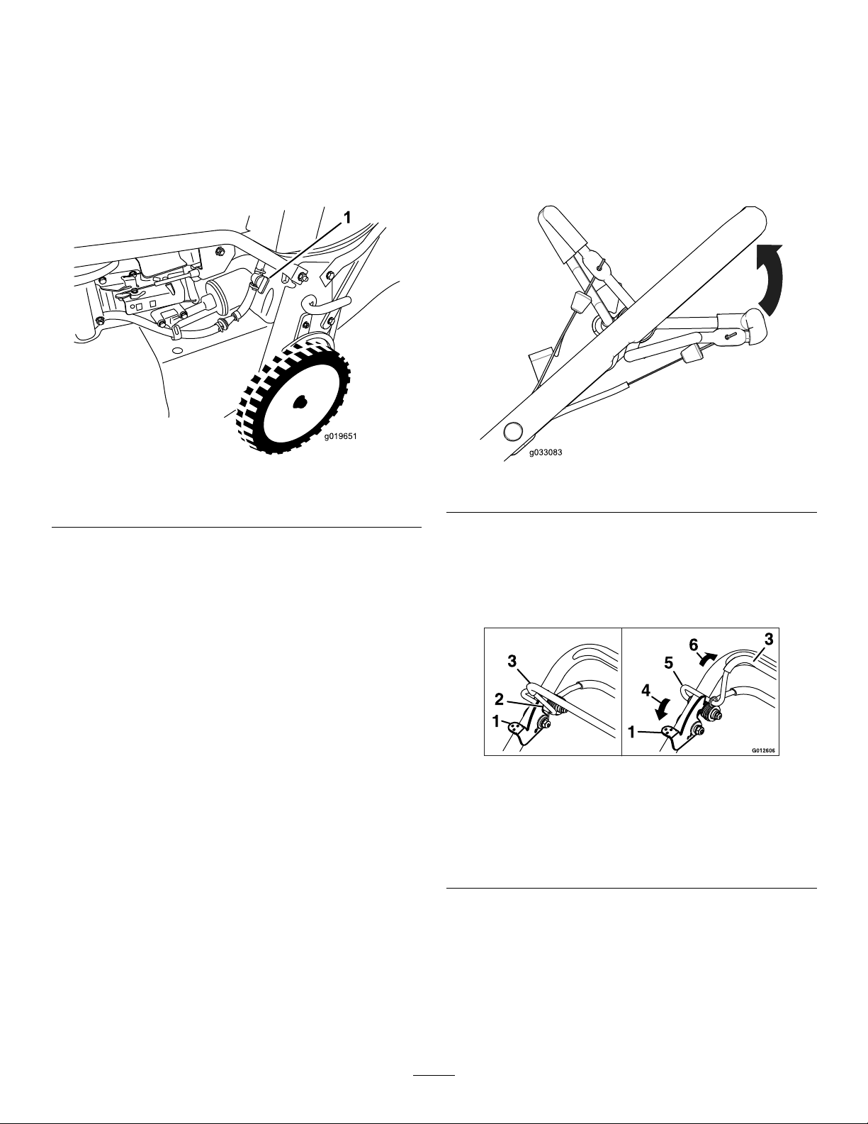
Arranquedelmotor
g019650
1
g019651
1
Utilizaciónde
1.Conecteelcabledelabujía(Figura9).
2.Abralaválvuladecierredelcombustible(Figura
18).
Nota:Cuandolaválvuladecierredel
combustibleestáabierta,lapalancaestá
paralelaaltubodecombustible.
Figura18
1.Válvuladecierredecombustible
latransmisión
autopropulsaday
activacióndelascuchillas
Parautilizarlatransmisiónautopropulsada,aprietela
barradeautopropulsióncontraelmanillar(Figura19).
g019651
Figura19
g033083
3.Muevaelcontroldelaceleradoralaposiciónde
ESTÁRTER(Figura11).
4.Tiresuavementedelarrancadorhastaquenote
resistencia,luegotireconfuerza.
5.Cuandoelmotorarranque,muevalapalancade
controldelaceleradoralaposicióndeRÁPIDO
(Figura10).
Nota:Sielmotornoarrancadespuésdetres
intentos,repitalospasos3a5.
Paradadelmotor
1.Muevaelcontroldelaceleradoralaposiciónde
PARADAyespereaquesedetengantodaslas
piezasenmovimiento.
2.Cierrelaválvuladecierredelcombustibley
desconecteelcabledelabujíasinovaautilizar
lamáquinaosilavaadejarsinsupervisar.
Paraengranarlascuchillas,hagalosiguiente:
1.Empujelapalancadebloqueodelabarrade
controldelascuchillashaciaadelantepara
liberarlabarradecontroldelascuchillas(Figura
20).
Figura20
1.Palancadebloqueode
controldelascuchillas
2.Posicióndebloqueado5.Posicióndedesbloqueado
3.Barradecontroldelas
cuchillas
2.Aprietelabarradecontroldelascuchillascontra
elmanillarysueltelapalancadebloqueodela
barradecontroldelascuchillas;lascuchillas
debenengranarse.
3.Sueltelabarradecontroldelascuchillaspara
desengranarlascuchillas.Lapalancade
bloqueovolveráasusitiooriginalparabloquear
labarradecontroldelascuchillas.
4.Empujar
6.Apretarcontraelmanillar
g012606
14
Page 51

Recicladodelosrecortes
G019812
1
G019798
2
Sumáquinavienepreparadadefábricaparareciclar
losrecortesdehierbayhojasydevolverlosalcésped.
Paraprepararlamáquinaparaelreciclado:
•Sielconductodedescargalateralestáinstalado
enlamáquina,retíreloeinstaleeldeector
dedescargalateral;consulteCómoretirarel
conductodedescargalateral(página16).
•Silabolsaderecogidaestáinstaladaenla
máquina,retírela;consulteCómoretirarlabolsa
derecogida(página15).
•Sieltapóndedescargatraseronoestáinstalado,
sujételoporelasa,eleveeldeectortraseroe
introdúzcaloenelconductodedescargatrasera
hastaqueelengancheencajeensusitio;consulte
Figura21.
g019798
Figura22
Figura21
1.Tapóndedescargatrasera
2.Deectortrasero
Ensacadodelosrecortes
Utilicelabolsaderecogidasidesearecogerlos
recortesdehierbayhojasdelcésped.
Sielconductodedescargalateralestáinstaladoen
lamáquina,retíreloeinstaleeldeectordedescarga
lateralantesdeensacarlosrecortes;consulte
Instalacióndelconductodedescargalateral(página
15).
Instalacióndelabolsaderecogida
1.Levanteysujeteeldeectortrasero(Figura22).
1.Varilladelabolsa
2.Retireeltapóndedescargatraseropresionando
haciaabajosobreelengancheconeldedo
pulgaryextrayendodeltapóndelamáquina
(Figura21).
3.Instalelavarilladelabolsaenlasmuescas
g019812
delabasedelmanillar,ymuevalabolsa
haciaadelanteyhacíaatrásparavericarque
lavarillaestáasentadaenelfondodecada
muesca;consulteFigura22.
4.Bajeeldeectortraserohastaquedescanse
sobrelabolsaderecogida.
2.Deectortrasero
Cómoretirarlabolsaderecogida
Pararetirarlabolsa,sigaensentidoinversolospasos
indicadosanteriormenteenInstalacióndelabolsa
derecogida.
Descargalateraldelos recortes
Utiliceladescargalateralparacortarhierbamuyalta.
Instalacióndelconductode
descargalateral
Importante:Asegúresedequeeltapónde
descargatraseraestácolocadoantesdereciclar
losrecortes.
1.Pareelmotoryespereaquesedetengantodas
laspiezasenmovimiento.
15
Page 52

2.Retirelabolsaderecogidasiestáinstaladaen
G019649
1
2
3
g019647
1
lamáquina;consulteCómoretirarlabolsade
recogida(página15).
3.Introduzcaeltapóndedescargatrasero;
consulteEnsacadodelosrecortes(página15).
4.Retireeldeectordedescargalateraltirando
haciaarribadelmuellequesujetaeldeectoren
susitioyretirandoeldeector(Figura23).
Figura23
1.Partesuperiordeldeector
dedescargalateral
2.Muelle
5.Parainstalarelconductodedescargalateral
(Figura24),tirehaciaarribadelmuelle,coloque
elconductosobrelaabertura,ybajeelmuelle
sobrelaspestañasdelapartesuperiordel
conductodedescarga.
3.Deectordedescarga
lateral
Cómoretirarelconductode
descargalateral
Pararetirarelconductodedescargalateral,invierta
lospasosdescritosenInstalacióndelconductode
descargalateral.
Consejosdeoperación
Consejosgenerales
•Reviselasinstruccionesdeseguridadylea
detenidamenteestemanualantesdeutilizarla
máquina.
•Despejelazonadepalos,piedras,alambres,
ramasyotrosresiduosquepodríansergolpeados
yarrojadosporlascuchillas.
•Mantengaatodoelmundo,especialmenteaniños
yanimales,alejadosdelaszonasdetrabajo.
•Evitegolpearárboles,muros,bordillosuotros
objetossólidos.Nosieguenuncaporencimade
ningúnobjeto.
•Silamáquinagolpeaunobjetooempiezaa
vibrar,pareinmediatamenteelmotor,desconecte
elcabledelabujíaeinspeccionelamáquinaen
g019649
buscadedaños.
•Mantengalascuchillasaladasdurantetodala
temporadadesiega.Devezencuando,elimine
lasmuescasdelascuchillasconunalima.
•Sustituyalascuchillascuandoseaprecisopor
cuchillasderepuestooriginalesdeT oro.
•Sieguesolamentehierbauhojassecas.Lahierba
mojadaylashojasmojadastiendenapegarseal
suelo,ypuedenatascarlamáquinaohacerque
secaleelmotor.
•Limpiedebajodelamáquinadespuésdecada
uso.ConsulteLimpiezadelosbajosdelamáquina
(página17).
•Mantengaelmotorenbuenascondicionesde
funcionamiento.
•Ajustelavelocidaddelmotoralaposiciónmás
rápidaparaconseguirresultadosóptimosdecorte.
•Limpieelltrodeaireconfrecuencia.Elpicadode
lahierbahacequeseformennubesderecortes
ypolvo,queatascanelltrodeaireyreducenel
rendimientodelmotor.
1.Conductodedescargalateral
Figura24
g019647
Cómocortarlahierba
•Lahierbacreceavelocidadesdistintassegúnla
estacióndelaño.Enelcalordelverano,esmejor
cortarlahierbausandolosajustesdealturade
cortede51mm(2"),64mm(2½")o83mm(3").
Cortesolamenteunterciodelahojadehierba
cadavez.Nocorteconunajusteinferiora51mm
16
Page 53

(2")amenosquelahierbaseaescasa,oanales
delotoñocuandoelritmodecrecimientodela
hierbaempiezaadecaer.
•Cuandocortehierbademásde15cm(6")dealto,
siegueprimerousandolaalturadecortemásalta
ycaminedespacio,luegosieguedenuevoauna
alturamenorparaobtenerelmejoraspectodel
césped.Silahierbaesdemasiadoaltaylashojas
seamontonanenelcésped,puedenatascarla
máquinayhacerquesecaleelmotor.
•Alterneladireccióndecorte.Estoayudaa
dispersarlosrecortesentodoelcésped,dando
unafertilizaciónmáshomogénea.
Sielaspectonaldelcéspednoessatisfactorio,
pruebeconunaomásdelastécnicassiguientes:
Seguridadduranteeltransporte
•Tengacuidadoalcargarodescargarlamáquina.
•Evitequelamáquinaruede.
Limpiezadelosbajosdela máquina
Paraobtenerunrendimientodecorteóptimo,
mantengalimpioslosbajosdelamáquina.Puede
eliminarlosrecortesdedebajodelamáquinacon
aguaorascando.
Lavadodelosbajosdelamáquina
•Alarlascuchillas.
•Caminarmásdespaciomientrassiega.
•Elevarlaalturadecortedelamáquina.
•Cortarelcéspedconmásfrecuencia.
•Solaparlospasillosdecorteenlugardecortarun
pasillocompletoencadapasada.
Cómocortarhojas
•Despuésdesegarelcésped,asegúresedequela
mitaddelcéspedseveatravésdelacoberturade
hojascortadas.Esposiblequetengaquehacer
másdeunapasadaporencimadelashojas.
•Paraunacoberturadehojasescasa,ajustetodas
lasruedasalamismaalturadecorte.
•Sieguemásdespaciosilamáquinanocortalas
hojassucientementenas.
Despuésdel
funcionamiento
Seguridaddespuésdeluso
Seguridadengeneral
•Limpielosrecortesdehierbaylosresiduosdela
máquinaparaayudaraprevenirincendios.Limpie
cualquieraceiteocombustiblederramado.
•Espereaqueseenfríeelmotorantesdeguardar
lamáquinaenunrecintocerrado.
Intervalodemantenimiento:Cadavezqueseutilice
odiariamente—Limpiedebajodela
carcasadelamáquina.
1.Coloquelamáquinasobreunasupercieplana
dehormigónoasfaltocercadeunamanguera
dejardín.
2.Arranqueelmotor.
3.Sujetelamangueraalaalturadelmanillary
dirijaelaguaparaqueuyasobreelsuelojusto
pordelantedelaruedatraseraderecha(Figura
25).
g002275
Figura25
1.Ruedatraseraderecha
Nota:Lascuchillasaspiraránaguay
expulsaránlosrecortes.Dejecorrerelagua
hastaquenoseveanrecortessaliendode
debajodelacarcasa.
4.Pareelmotoryespereaquesedetengantodas
laspiezasenmovimiento.
5.Cierreelgrifo.
6.Arranquelamáquinaydéjelafuncionardurante
unosminutosparaeliminarlahumedaddela
máquinaysuscomponentes.
•Noguardenuncalamáquinaounrecipientede
combustiblecercadeunallamadesnuda,chispa
ollamapiloto,porejemploenuncalentadorde
aguauotroelectrodoméstico.
17
Page 54

Rascadodelosbajosdela
máquina
Siellavadonoeliminatodoslosresiduosdedebajo
delamáquina,rásquelahastaqueestélimpia.
1.Desconecteelcabledelabujía.
2.Dreneelcombustibledeldepósitode
combustible;consulteVaciadodeldepósitode
combustibleylimpiezadelltro(página23).
3.Coloquelamáquinadelado,conelltrode
airehaciaarriba,hastaqueelmanillarsuperior
descansesobreelsuelo.
4.Eliminelasuciedadylosrecortesdehierbacon
unrascadordemaderadura;evitelasrebabas
ylosbordesalados.
5.Pongalamáquinadepie.
6.Lleneeldepósitodecombustible.
7.Conecteelcabledelabujía.
Limpiezadelasruedas
Intervalodemantenimiento:Cada40horas
1.Retirelasruedastraserasylimpiecualquier
suciedaddelazonadelaruedaydelos
engranajes.
g196471
Figura26
1.Engranajes
2.Despuésdelalimpieza,apliqueunapequeña
cantidaddeantigripantealosengranajes.
Nota:Siseutilizalamáquinaencondiciones
extremas,unalimpiezamásfrecuentedelasruedas
aumentarálavidaútildelosengranajes.
Nota:Paraevitardañarlasjuntasdecojinete,no
utiliceunpulverizadordeaguadealtapresiónsobre
loscojinetes.
18
Page 55

Mantenimiento
Nota:Losladosderechoeizquierdodelamáquinasedeterminandesdelaposiciónnormaldeloperador.
PuedeadquirirpiezasderepuestoenunServicioTécnicoAutorizadooenwww.torodealer.com(clientesdeEE.
UU.solamente).LaspiezasdelmotorestándisponiblesúnicamenteenunServicioTécnicoAutorizado.
Calendariorecomendadodemantenimiento
Intervalodemanteni-
mientoyservicio
Despuésdelasprimeras
5horas
Cadavezqueseutilice
odiariamente
Cada25horas
Cada40horas
Cada50horas
Cada100horas
Procedimientodemantenimiento
•Cambieelaceitedelmotorsinelltrodeaceite.
•Realiceelmantenimientodelsistemadetransmisióndelascuchillas.
•Comprobacióndelniveldeaceitedelmotor.
•Compruebeelfuncionamientodelsistemadefrenadodelascuchillas.Lascuchillas
debenpararseen3segundosomenosdespuésdesoltarlabarradecontrol;sino
lohacen,póngaseencontactoconunServicioTécnicoAutorizado.
•Limpiedebajodelacarcasadelamáquina.
•Inspeccioneelltrodeaire.
•Compruebelascuchillasyrealiceelmantenimientonecesario.
•Inspeccionelascuchillas.
•Limpieelpre-limpiadordegomaespuma(conmásfrecuenciaencondicionesde
muchopolvo).
•Limpielasruedasylosengranajes.
•Cambieelaceitedelmotor;cámbieloconmásfrecuenciaencondicionesdemucho
polvo.
•Compruebelacondicióndelascorreas.
•Compruebeeltubodecombustibleycámbielosiesnecesario.
•Eliminelosresiduosdedebajodelacubiertadelacorrea.
•Realiceelmantenimientodelsistemadetransmisióndelascuchillas.
•Cambieelltrodeaceite.
•Compruebelabujía.
•Limpieelltrodeldepósitodecombustible.
•Cambieelltrodecombustible.
Cada250horas
Cada300horas
Cadaañooantesdel
almacenamiento
•Cambielacorreadelembraguedelfrenodelacuchilla.
•Cambielacorreadelatransmisión.
•Cambieelltrodeairedepapel(conmásfrecuenciaencondicionesdemucho
polvo).
•Vacíeeldepósitodecombustibleantesdeefectuarreparaciones,segúnlas
instrucciones,oantesdelalmacenamiento.
Importante:Consultelosprocedimientosadicionalesdemantenimientoenelmanualdelmotor.
Seguridadenelmantenimiento
•Desconecteelcabledelabujíaantesderealizarcualquierprocedimientodemantenimiento.
•Lleveguantesyprotecciónocularalrealizarelmantenimientodelamáquina.
•Lacuchillaestámuyalada;cualquiercontactoconlacuchillapuedecausarlesionespersonalesgraves.
Lleveguantesalrealizarelmantenimientodelacuchilla.
•Nomanipulenuncalosdispositivosdeseguridad.Comprueberegularmentequefuncionancorrectamente.
•Alvolcarlamáquina,puedehaberfugasdecombustible.Elcombustibleesinamableyexplosivo,ypuede
causarlesionespersonales.Dejefuncionarelmotorhastaquenoquedecombustible,oretirelagasolina
conunabombademano;nuncautiliceunsifón.
19
Page 56

Mantenimientodelltrode
aire
Intervalodemantenimiento:Cadavezqueseutilice
odiariamente
Cada25horas—Limpieelpre-limpiador
degomaespuma(conmásfrecuenciaen
condicionesdemuchopolvo).
Cada300horas—Cambieelltrodeairede
papel(conmásfrecuenciaencondicionesde
muchopolvo).
Importante:Nohagafuncionarelmotorsinel
conjuntodeltradodeaire,porqueseproducirán
gravesdañosalmotor.
1.Pareelmotoryespereaquesedetengantodas
laspiezasenmovimiento.
2.Desconecteelcabledelabujía.
3.Retirelatapaylímpielaafondo(Figura27).
Nota:Noañadaaceitealpre-limpiadorde
gomaespuma.
7.Instaleelpre-limpiadordegomaespumasobre
elltrodepapel.
8.Instaleelconjuntodelltrodeaire.
9.Coloquelatapa.
Figura27
1.Tapa
2.Preltrodegomaespuma
yltrodepapel
4.Retireelpreltrodegomaespumayelltrode
papel(Figura27).
5.Retireelpreltrodegomaespumadelltrode
papel(Figura27)ysustituyaelltrodepapelsi
estáexcesivamentesucio.
3.Basedelltrodeaire
Importante:Nointentelimpiarelltrode
papel.
6.Laveelprelimpiadordegomaespumacon
detergentesuaveyagua,luegoséquelo
apretandoconunpaño.
g006591
20
Page 57

Cómocambiarelaceitedel
G019648
motor
Intervalodemantenimiento:Despuésdelas
primeras5horas—Cambieelaceite
delmotorsinelltrodeaceite.
Cada50horas—Cambieelaceitedelmotor;
cámbieloconmásfrecuenciaencondiciones
demuchopolvo.
Nota:Hagafuncionarelmotorduranteunosminutos
antesdecambiarelaceiteparacalentarelaceite.
Elaceitecalienteuyemejorytransportamás
contaminantes.
Capacidaddeaceitedelmotor:conltrodeaceite:
0,85l(29onzas);sinltrodeaceite:0,65l(22onzas)
Viscosidaddelaceite:AceitedetergenteSAE30
oSAE10W-30
ClasicaciónAPI:SJosuperior
1.Llevelamáquinaaunasupercienivelada.
2.ConsulteSeguridadenelmantenimiento
(página19).
3.Retirelavarillagirandoeltapónenelsentido
contrarioalasagujasdelrelojytirandodel
mismo(Figura28).
g019648
Figura29
5.Despuésdedrenarelaceiteusado,pongala
máquinaensuposicióndeuso.
6.Concuidado,viertatrescuartaspartes
aproximadamentedelacapacidadtotalde
aceitedelmotoreneltubodellenado.
7.Espereunos3minutosparaqueelaceitese
asienteenelmotor.
8.Limpielavarillaconunpañolimpio.
9.Introduzcalavarillaeneltubodellenadode
aceite,luegoretírela.
10.Observeelniveldeaceiteenlavarilla(Figura
28).
Figura28
1.Marca3.Bajo
2.Alto
4.Pongalamáquinadelado(conelltrodeaire
haciaarriba)paradrenarelaceiteusadodel
tubodellenadodeaceite(Figura29).
•Sielniveldeaceiteestápordebajodela
marcaAdd(Añadir)delavarilla,viertauna
pequeñacantidaddeaceitelentamenteen
eltubodellenado,espere3minutos,yrepita
lospasos8a10hastaqueelnivellleguea
lamarcaFull(Lleno)delavarilla.
•Sielniveldeaceiteestáporencimadela
marcaLlenodelavarilla,dreneelexcesode
aceitehastaqueelnivellleguealamarca
Llenodelavarilla.
Importante:Sielniveldeaceitedelmotor
esdemasiadobajoodemasiadoaltoyusted
g194742
arrancaelmotor,puededañarelmotor.
11.Instalelavarillarmemente.
12.Reciclecorrectamenteelaceiteusado.
21
Page 58

Cómocambiarelltrode
g019650
1
aceite
Intervalodemantenimiento:Cada100horas
1.Hagafuncionarelmotorparacalentarelaceite.
2.Pareelmotoryespereaquesedetengantodas
laspiezasenmovimiento.
3.Desconecteelcabledelabujía.
4.Dreneelaceitedelmotor;consulteCómo
cambiarelaceitedelmotor(página21).
5.Coloqueuntrapodebajodelltrodeaceitepara
recogercualquieraceitequesesalgamientras
retiraelltro.
6.Retireelltrodeaceite(Figura30).
Nota:Asegúresederetirarlajuntadelltrode
aceiteconelltro.
8.Instaleelltronuevohastaquelajuntatoquela
basedelltro,luegoaprieteelltro2/3vuelta
másamano.
9.Lleneelcárterconaceitenuevohastalamarca
Full(lleno)delavarilla;consulteCómocambiar
elaceitedelmotor(página21).
10.Conecteelcabledelabujía.
11.Hagafuncionarelmotorduranteunos3minutos.
12.Pareelmotor,espereaquesedetengantodas
laspiezasenmovimientoycompruebequeno
hayfugasdeaceitealrededordelltro.
13.Añadaaceiteparacompensarelaceitequeestá
enelltrodeaceite;consulteCómocambiarel
aceitedelmotor(página21).
14.Recicleelltrodeaceiteusadosegúnla
normativalocal.
Mantenimientodelabujía
Intervalodemantenimiento:Cada100horas
Figura30
1.Filtrodeaceite
7.Usandoeldedo,untelajuntadelltronuevo
conaceite(Figura31).
UtiliceunabujíaNGKBPR5ESoequivalente.
1.Pareelmotoryespereaquesedetengantodas
laspiezasenmovimiento.
2.Desconecteelcabledelabujía.
3.Limpiealrededordelabujía.
4.Retirelabujíadelaculata.
Importante:Silabujíaestáagrietadao
sucia,cámbiela.Nolimpieloselectrodos,
g019650
porquecualquierarenillaqueentreenel
cilindropuededañarelmotor.
5.Ajusteelespacioentreloselectrodosa0,76mm
(0.030");consulteFigura32.
g000533
Figura32
1.Aislantedelelectrodo
central
g002805
Figura31
1.Junta
2.Electrodolateral
6.Instalelabujíaylajunta.
7.Aprietelabujíaa23N·m(17pies-libra).
22
3.Distanciaentreelectrodos
(noaescala)
Page 59

8.Conecteelcablealabujía.
g019650
1
g019924
1
2
deltubodecombustibleenunrecipientede
combustiblehomologado.
Comprobacióndela condicióndelascorreas
Intervalodemantenimiento:Cada50horas
1.Pareelmotoryespereaquesedetengantodas
laspiezasenmovimiento.
2.Retirelacubiertadelacorrea(Figura9)
retirandolos4pernosquelasujetanala
carcasadelamáquina.
3.Compruebequelascorreasnotienengrietas,
bordesdeshilachados,marcasdequemaduras
uotrosdaños.
4.Sustituyacualquiercorreadañada.
5.Sicambialacorreadetransmisióndelas
cuchillas,seránecesarioajustarla.Consulte
Mantenimientodelsistemadetransmisiónde
lascuchillas(página24).
6.Instalelacubiertadelacorreausandolos4
pernosqueseretiraronenelpaso2.
6.Retireeldepósitodecombustibledelamáquina.
7.Viertaunapequeñacantidaddecombustible
eneldepósitodecombustible,muevael
combustibledentrodeldepósitoyvacíeloenun
recipientedecombustiblehomologado.
8.Instaleeldepósitodecombustibleyeltubode
combustible.
Cambiodelltrode
combustible
Intervalodemantenimiento:Cada100horas
1.Pareelmotoryespereaquesedetengantodas
laspiezasenmovimiento.
2.Desconecteelcabledelabujía.
3.Cierrelaválvuladecierredelcombustible
(Figura33).
Vaciadodeldepósitode
combustibleylimpiezadel
ltro
Intervalodemantenimiento:Cada50
horas—Compruebeeltubode
combustibleycámbielosies
necesario.
Cada100horas—Limpieelltrodeldepósito
decombustible.
Cadaañooantesdelalmacenamiento—Vacíe
eldepósitodecombustibleantesdeefectuar
reparaciones,segúnlasinstrucciones,oantes
delalmacenamiento.
Nota:Elelemento(lamalla)delltrodeldepósito
decombustibleseencuentradentrodeldepósitode
combustible,enlasalida.Esteltroformapartedel
depósitodecombustibleynopuedeserretirado.
1.Apagueelmotoryespereaqueseenfríe.
Importante:Dreneelcombustible
solamentecuandoelmotorestáfrío.
2.Desconecteelcabledelabujía.
3.Cierrelaválvuladecierredelcombustible.
4.Desconecteeltubodecombustibleaojandola
abrazaderaenelcarburador.
5.Abralaválvuladecierredecombustible,ydrene
completamenteelcombustibledeldepósitoy
g019924
Figura33
1.Filtrodecombustible2.Válvuladecierrede
combustible
4.Retireelltrodecombustible(Figura33)del
tubodecombustibleaojandolasabrazaderas
decadaladodelltrodecombustible.
5.Instaleunltrodecombustiblenuevoeneltubo
decombustibleusandolasabrazaderasquese
retiraronenelpaso4.
23
Page 60

Mantenimientodelsistema detransmisióndelas cuchillas
Intervalodemantenimiento:Despuésdelas
primeras5horas
Cada50horas—Eliminelosresiduosdedebajo
delacubiertadelacorrea.
Cada50horas—Realiceelmantenimientodel
sistemadetransmisióndelascuchillas.
1.Aojelos2tornillosdelpaneldeaccesoala
cubiertadelacorreayretireelpanel(Figura34).
Nota:Sihayunespaciovisibleentrelagalga
yelmuelle,aprieteelpernodeajusteyla
contratuercahastaquelagalgaapenaspueda
deslizarselibrementeporelespacio(Figura34).
Importante:Noaprietedemasiadoelperno
deajuste.Estopodríadañarlacorreade
transmisióndelascuchillas.
4.Instaleelpaneldeaccesoalacubiertadela
correa.
Mantenimientodelas cuchillas
Intervalodemantenimiento:Cadavezqueseutilice
odiariamente
Importante:Necesitaráunallavedinamométrica
parainstalarlascuchillascorrectamente.Sino
disponedeunallavedinamométricaopreereno
realizaresteprocedimiento,póngaseencontacto
conelServicioTécnicoAutorizado.
Figura34
1.Muelletensordelacorrea
2.Pernodeajuste6.T abique
3.Espacio
4.Tuercadeajuste8.Paneldeaccesoala
2.Limpielosresiduosdelinteriordelacubierta
delacorreaydealrededordetodaslaspiezas
usandouncepillooaireapresión.
3.Sujeteunagalgaajustadaaentre0.13mm
y0.76mm(0.005"y0.03")contraeltabique
ydeslícelahaciaabajopordetrásdelmuelle
tensordelacorrea;consulteFigura35.
5.Correadetransmisiónde
lascuchillas
7.Cubiertadelacorrea
cubiertadelacorrea
Cadavezqueseacabeelcombustible,examine
cuidadosamentelascuchillasparaasegurarsede
queestánaladasyquenoestándesgastadasni
dañadas;consulteInspeccióndelascuchillas(página
25).Siellodeunacuchillaestáromootiene
desperfectos,mandealarlacuchillaocámbiela.Si
g208925
lascuchillasestándesgastadas,dañadas,dobladaso
agrietadas,sustitúyalasinmediatamenteporcuchillas
derepuestogenuinasdeToro.
PELIGRO
Unacuchilladesgastadaodañadapuede
romperse,yuntrozodelacuchillapodríaser
arrojadohaciaeloperadoruotrapersona,
provocandolesionespersonalesgravesola
muerte.
•Inspeccioneperiódicamentelascuchillas,
paraasegurarsedequenoestán
desgastadasnidañadas.
•Sustituyacualquiercuchillaqueesté
desgastadaodañada.
Figura35
Nota:Mantengalascuchillasaladasdurantetodala
temporadadecorte,yaqueunacuchillaaladacorta
limpiamenteysinrasgarodeshilacharlashojasde
hierba.Siserasganosedeshilachan,losbordesde
lashojassesecarán,locualretardarásucrecimiento
yfavorecerálaaparicióndeenfermedades.
decal116-8528
24
Page 61

Preparaciónparaelmantenimiento
g017223
delascuchillas
Coloquelamáquinadelado,conelltrodeairehacia
arriba,hastaqueelmanillarsuperiordescansesobre
elsuelo.
ADVERTENCIA
Lascuchillasestánmuyaladas;cualquier
contactoconunacuchillapuedecausar
lesionespersonalesgraves.
•Desconecteelcabledelabujía.
•Lleveguantespararealizarel
mantenimientodelascuchillas.
Inspeccióndelascuchillas
Intervalodemantenimiento:Cadavezqueseutilice
odiariamente
1.Inspeccioneloslosdecorte(Figura36).Si
loslosdecortenoestánaladosotienen
muescas,retirelascuchillasyhagaquelas
alenocámbielas.
PELIGRO
Sipermitequesedesgasteunacuchilla,
seformaráunaranuraentrelavelay
laparteplanadelacuchilla.Conel
tiempo,unapartedelacuchillapuede
desprenderseyserarrojadadesde
debajodelacarcasa,posiblemente
causandolesionesgravesaustedoa
otrapersona.
•Inspeccioneperiódicamentelas
cuchillas,paraasegurarsedequeno
estándesgastadasnidañadas.
•Nointenteenderezarunacuchilla
doblada,ynosueldenuncauna
cuchillarotaoagrietada.
•Compruebequelascuchillasnoestán
dobladas;consulteVericacióndela
rectilinealidaddelascuchillas(página
26).
Figura36
1.Partecurva3.Formaciónde
2.Filodecorte
2.Inspeccionelascuchillas,especialmentela
partecurva(Figura42).Siobservacualquier
dañoodesgaste,olaformacióndeunaranura
enestazona(Figura36),cambielascuchillas
inmediatamenteporcuchillasnuevas.
ranura/desgaste
4.Grieta
g017223
25
Page 62

Vericacióndelarectilinealidad
B
B
2
1
3
g016532
G016530
1
2
3
4
Cómoretirarlascuchillas
delascuchillas
1.Girelascuchillashastaqueesténposicionadas
segúnsemuestraenFigura37.
Figura37
1.Partedelanteradela
carcasadecorte
2.MidaenlasposicionesA
yB
3.Midadesdeellodecorte
hastaunasupercielisay
nivelada
Cambielascuchillassigolpeanunobjetosólido,o
siestándesequilibradas,dobladasodesgastadas.
Utilicesolamentecuchillasderepuestogenuinasde
Toro.
1.Utiliceunbloquedemaderaparainmovilizar
cadacuchillaygireelpernodelacuchillaenel
sentidocontrarioalasagujasdelreloj,segúnse
muestraenFigura38.
g016532
g016527
Figura38
2.Midadesdeunasupercieniveladahastalos
losdecorte,enlasposicionesAyB(Figura
37)yanotelasdimensiones.
3.Girelascuchillasdemaneraquesusextremos
opuestosestánenlasposicionesAyB.
4.Repitalasmedicionesdelpaso2yanótelas.
Nota:SiladiferenciaentrelasdimensionesA
yBobtenidasenlospasos2y4essuperior
a3mm(1/8"),cambielascuchillas;consulte
Cómoretirarlascuchillas(página26).
ADVERTENCIA
Unacuchilladobladaodañadapodría
romperseypodríacausargraves
lesionesolamuerteaustedoaotras
personas.
•Siempresustituyaunacuchilla
dobladaodañadaporunacuchilla
nueva.
•Nuncalimenicreemuescasaladas
enlosbordesoenlasuperciedela
cuchilla.
2.Retirecadacuchilla,segúnsemuestraen
Figura39.
g016530
Figura39
1.Eje(2)3.Cuchilla(2)
2.Impulsordelacuchilla(2)4.Pernodelacuchilla(2)
3.Inspeccionelasclavijasdelosimpulsoresdelas
cuchillasenbuscadedesgasteodaño.
26
Page 63

Instalacióndelascuchillas
g016537
1
G016536
mismamaneraquelaprimera(consulteelpaso
1).
ADVERTENCIA
Unainstalaciónincorrectadelascuchillas
podríadañarlamáquinaycausarlesionesal
operadoroaotraspersonas.
Instalelascuchillasconarregloalas
instrucciones.
1.Instalelaprimeracuchillaenposiciónhorizontal,
juntocontodoslosherrajesdemontaje,según
semuestraenFigura39.
Nota:Aprieteelpernoconlosdedos.
Importante:Coloquelascuchillascon
losextremoscurvoshacialacarcasadela
máquina.Asegúresedeencajarlaszonas
elevadasdelimpulsordelacuchillaen
loshuecosdelejecorrespondiente,ylas
clavijasdelotroladodelimpulsorenlos
taladrosdelacuchillacorrespondiente.
2.Inmovilicecadacuchillaconunatablade
madera,ygireelpernodelacuchillaensentido
horarioconunallavedinamométrica,segúnse
muestraenFigura40;aprieteelpernodecada
cuchillaa82N·m(60pies-libra).
Nota:Lascuchillasdebenestar
perpendicularesentresí,formandouna
“T”invertida,segúnsemuestraenFigura41.
g016536
Figura41
1.Cuchilla(2)
4.Aprietelasegundacuchilla;consulteelpaso2.
5.Girelascuchillasamanouncírculocompletode
360°paraasegurarsedequenosetocan.
Nota:Silascuchillassetocan,noestán
montadascorrectamente.Repitalospasos1a
3hastaquelascuchillasnosetoquen.
Cambiodelacorreade transmisióndelascuchillas
Cambielacorreadetransmisióndelascuchillas
segúnseanecesario.
1.Pareelmotoryespereaquesedetengantodas
laspiezasenmovimiento.
2.Desconecteelcabledelabujía.
3.Retirelacubiertadelacorrea(Figura9)
retirandolos4pernosquelasujetanala
carcasadelamáquina.
Nota:Guardelospernosparainstalarla
cubiertadelacorreaenlacarcasadela
máquina.
4.Eliminelosresiduosdedebajodelacubierta
g016537
Figura40
Importante:Unpernoapretadoa82N·m
(60pies-libra)quedamuyrme.Aprieteel
pernormementecontodasufuerza.Es
muydifícilapretarestepernodemasiado.
3.Girelacuchilla1/4devueltahastaqueestéen
posiciónvertical,einstalelaotracuchilladela
delacorrea.
5.RetireelprotectordelEFCylosherrajesde
montaje.
Nota:GuardeelprotectordelacorreadelEFC
ylosherrajesparasuinstalaciónposterior.
27
Page 64

Figura42
1.CorreadelEFC
2.Protectordelacorreadel
EFC
6.RetirelacorreadelEFCdelapoleaizquierda
delantera.
7.Aojeelpernodeajuste(Figura34).
8.Retirelapoleatensorajaylosherrajes(Figura
43).
Nota:Guardelapoleatensoraylosherrajes
parasuinstalaciónposterior.
10.Alineelostaladrosdelospiñonesdelaizquierda
ydeladerechaconlostaladrosdelacarcasa,
segúnsemuestraenFigura43.
Nota:Sujetelospiñonesensusitioconuna
varillaoundestornillador.
11.Cuandohayabloqueadolospiñonesensusitio,
instalelacorreadetransmisióndelascuchillas
ylapoleatensoraja.
Nota:Asegúresedequelosdientesestán
engranadosenlospiñones.
12.Ajustelatensióndelacorreaalapriete
recomendado;consulteMantenimientodel
g208922
sistemadetransmisióndelascuchillas(página
24).
13.Retirelavarillaoeldestornilladordelospiñones.
14.Compruebequelascuchillassituadasdebajo
delacarcasaestáncorrectamentealineadas;
consulteMantenimientodelascuchillas(página
24).
15.InstalelacorreadelEFCyelprotector
delacorreadelEFCconsusherrajes
correspondientes.
16.Instalelacubiertadelacorreausandolos4
pernosqueretiróenelpaso3.
17.Conecteelcablealabujía.
18.Compruebeelfuncionamientodelabarrade
controlydelembraguedelfrenodelacuchilla.
Figura43
LapoleatensoradelEFCseharetiradoparamayor
claridad
1.Taladrodelacarcasa
2.Taladrodelpiñóndela
derecha
3.Poleatensoraja
4.Taladrodelpiñóndela
izquierda
9.Retirelacorreadetransmisióndelascuchillas.
Cambiodelacorreadel embraguedelfrenodelas cuchillas(EFC)
Intervalodemantenimiento:Cada250horas
1.Pareelmotoryespereaquesedetengantodas
laspiezasenmovimiento.
2.Desconecteelcabledelabujía.
3.Retirelos4pernosquesujetanlacubiertadela
correaalacarcasadelamáquina.
g208924
Nota:Guardelospernosparainstalarla
cubiertadelacorreaenlacarcasadela
máquina.
4.Retirelacubiertadelacorrea.
5.Eliminelosresiduosdedebajodelacubierta
delacorrea.
6.Retirelacorreadetransmisióndelcepillo;
consulteCambiodelacorreadelatransmisión
(página30).
7.RetireelprotectordelacorreadelEFC(Figura
44).
28
Page 65

Nota:Guardelosherrajesdemontajeparala
reinstalaciónposteriordelprotectordelEFC.
Figura44
1.CorreadelEFC
8.RetirelacorreadelEFCdelapoleadeltambor
delfreno,yretirelacorreadelamáquina.
2.Protectordelacorreadel
EFC
g208921
Figura45
g208922
1.Tornillodelaabrazadera
2.Cabledelfrenodela
cuchilla
6.Tiredelacubiertadelcableparaeliminarla
holgura(Figura46).
Nota:Notenseelmuelle.
Nota:Sujeteunadelascuchillasusandoun
guanteountrapo,ygireelejedelacuchilla
parafacilitarlaretiradadelacorreadelEFC.
9.ParainstalarunacorreadeEFCnueva,sigalos
pasosanterioresensentidoinverso.
10.AjusteelcabledelEFC;consulteAjustedel
cabledelfrenodelacuchilla(página29).
Ajustedelcabledelfreno delacuchilla
Ajusteelcabledelfrenodelacuchillacadavezque
instaleuncablenuevoocambielacorreadelEFC.
1.Pareelmotoryespereaquesedetengantodas
laspiezasenmovimiento.
2.Desconecteelcabledelabujía.
3.Retirelacubiertadelacorrea(Figura9)
retirandolos4pernosquelasujetanala
carcasadelamáquina.
Nota:Guardelospernosparainstalarla
cubiertadelacorreaenlacarcasadela
máquina.
g208926
Figura46
7.Marqueelcabledefreno(Figura47),
luegoajustelacubiertahastaquequede
aproximadamente3mm(1/8")deholgura
(Figura48).
4.Eliminelosresiduosdedebajodelacubierta
delacorrea.
5.Aojeeltornillodelaabrazadera(Figura45).
29
Page 66

Cambiodelacorreadela transmisión
Intervalodemantenimiento:Cada250horas
1.Pareelmotoryespereaquesedetengantodas
laspiezasenmovimiento.
2.Desconecteelcabledelabujía.
3.Retirelos4pernosquesujetanlacubiertadela
correaalacarcasadelamáquina.
Figura47
1.Marqueelcableaquí
Figura48
1.Holgura–3mm(1/8")
8.Aprieteeltornillodelaabrazaderadelcable
a11–14N·m(99–121pulgadas-libra)para
aanzarelajuste.
9.Instalelacubiertadelacorreausandolos4
pernosqueretiróenelpaso3.
10.Conecteelcablealabujía.
11.Compruebelaoperacióndelembraguedelfreno
delacuchilla;consulteMantenimientodelas
cuchillas(página24).
g208923
Nota:Guardelospernosparainstalarla
cubiertadelacorreaenlacarcasadela
máquina.
4.Retirelacubiertadelacorrea.
5.Eliminelosresiduosdedebajodelacubierta
delacorrea.
6.Aojeelsoporteygireelsoportehaciaadelante
(Figura49).
Nota:Elsoporteevitaquelatransmisión
seinclinedemasiadoyquelacorreadela
transmisiónsesalgadelapolea.
g208920
g196531
Figura49
1.Muelletensordela
transmisión
2.Soporte5.Correadelatransmisión
3.Transmisión
7.Retireelmuelletensordelatransmisión.
4.CorreadelEFC
8.Retirelacorreadelatransmisióndelapolea
detransmisión.
9.Retirelacorreadelatransmisión.
10.Parainstalarunacorreadetransmisiónnueva,
inviertalospasosanteriores.
30
Page 67

Ajustedelatransmisión
Silamáquinaempiezaaperdertracción,compruebe
yajustelatransmisión.
1.Pareelmotoryespereaquesedetengantodas
laspiezasenmovimiento.
2.Desconecteelcabledelabujía.
3.Aojeelpernoylatuercaquesujetanelsoporte
ensusitio.
4.Ajusteelsoportehastaqueestéencontacto
conlatransmisión.
Nota:Elsoporteevitaquelatransmisión
seinclinedemasiadoyquelacorreadela
transmisiónsesalgadelapolea.
5.Aprieteelpernoylatuercaparasujetarel
soporteensusitio.
Ajustedelcable
delatransmisión
g005011
Figura51
4.Aprietelatuercadelsoportedelcable.
5.Compruebequeelcontroldetransmisión
funcionacorrectamente.
Nota:Silamáquinaavanzalentamentesinqueesté
engranadalabarradecontrol,osilasruedaspatinan
allevantarlasruedastraserasdelsuelo,elcableestá
demasiadoapretado;repitalospasos1y2.
autopropulsada
Silamáquinanoavanzaautomáticamenteositiene
tendenciaaavanzarlentamentedespuésdesoltarla
barradecontrol,ajusteelcabledelatransmisión.
1.Pareelmotoryespereaquesedetengantodas
laspiezasenmovimiento.
2.Aojelatuercadelsoportedelcable(Figura50).
Figura50
Nota:Esposibleajustarelmecanismoparaobtener
lavelocidaddeavancedeseadaenlaposiciónde
máximorecorridodelabarradecontrol,loque
permiteutilizarvelocidadesmáslentas.
g005013
3.Tirehaciaabajodelacubiertadelcable(hacia
elcortacésped)hastaeliminarlaholguraenel
cable(Figura51).
31
Page 68

Almacenamiento
Informacióngeneral
Almacenelamáquinaenunlugarfresco,limpioy
seco.Cubralamáquinaparamantenerlalimpiay
protegida.
1.Realicelosprocedimientosdemantenimiento
anualrecomendados;consulteMantenimiento
(página19).
2.Limpiedebajodelamáquina;consulteLimpieza
delosbajosdelamáquina(página17).
3.Eliminelabroza,lasuciedadylagrasadelas
piezasexternasdelmotor,lacubiertaylaparte
superiordelacarcasadelamáquina.
4.Compruebelacondicióndelascuchillas;
consulteInspeccióndelascuchillas(página25).
5.Reviseelltrodeaire;consulteMantenimiento
delltrodeaire(página20).
6.Aprietetodoslospernos,tuercasytornillos.
7.Retoquetodaslassuperciespintadasoxidadas
odescascarilladasconpintura,quepuede
adquirirenelServicioTécnicoAutorizado.
2.Arranqueelmotordenuevo.
3.Dejequefuncioneelmotorhastaquesepare.
Cuandoyanosepuedearrancarelmotor,está
sucientementeseco.
Preparacióndelmotor
1.Conelmotortodavíacaliente,cambieelaceite
delmotoryelltrodeaceite;consulteCómo
cambiarelaceitedelmotor(página21)yCómo
cambiarelltrodeaceite(página22).
2.Retirelabujía.
3.Usandounaaceitera,añadaaproximadamente
30ml(1onza)deaceitedemotoralmotora
travésdeloriciodelabujía.
4.Tiredelacuerdadelarrancadorlentamente
variasvecesparaquesedistribuyaelaceitepor
elcilindro.
5.Instalelabujíaperonoconecteelcableala
bujía.Amarreelcableparaquenopuedaentrar
encontactoconlabujía.
Despuésdelalmacena-
Preparacióndelsistemade combustible
ADVERTENCIA
Elcombustiblepuedevaporizarsesila
almacenaporlargosperiodosdetiempo,y
puedeexplosionarsientraencontactocon
unallamadesnuda.
•Noalmacenecombustibleporlargos
periodosdetiempo.
•Noalmacenelamáquinaenunlugar
cerradoconllamadesnudasihay
combustibleeneldepósitooenel
carburador.(Porejemplo,lallamapilotode
unacalderaodeuncalentadordeagua).
•Espereaqueseenfríeelmotorantes
deguardarelcortacéspedenunrecinto
cerrado.
Enelúltimorepostajedelaño,añadaestabilizadoral
combustiblesiguiendolasinstruccionesdelfabricante
delmotor.Vacíeeldepósitodecombustibledurante
laúltimaoperacióndesiegaantesdealmacenarla
máquina.
1.Hagafuncionarlamáquinahastaqueelmotor
separeporhabersequedadosingasolina.
miento
1.Compruebeyaprietetodosloscierres.
2.Retirelabujíayhagagirarelmotorrápidamente
usandoelarrancadorparaeliminarelexceso
deaceitedelcilindro.
3.Inspeccionelabujíaycámbielasiestásucia,
desgastadaoagrietada;consulteelManualdel
propietariodelmotor.
4.Instalelabujíayapriételaalparrecomendado
de20N·m(180pulgadas-libra).
5.Lleveacabocualquierprocedimiento
demantenimientonecesario;consulte
Mantenimiento(página19).
6.Compruebeelniveldeaceitedelmotor;consulte
Comprobacióndelniveldeaceitedelmotor
(página11).
7.Lleneeldepósitodecombustiblecon
combustiblefresco;consulteCómollenarel
depósitodecombustible(página10).
8.Conecteelcabledelabujía.
32
Page 69

Solucióndeproblemas
ProblemaPosiblecausa
Elmotornoarranca.
Elmotorarrancacondicultadopierde
potencia.
Accióncorrectora
1.Eldepósitodecombustibleestávacío
oelsistemadecombustiblecontiene
combustibleviejo.
2.Laválvuladecierredecombustible
estácerrada.
3.Lapalancadelaceleradornoestáen
laposicióncorrecta.
4.Haysuciedad,aguaocombustible
viejoenelsistemadecombustible.
5.Elcablenoestáconectadoalabujía.
6.Labujíaestápicada,suciaola
distanciaentreloselectrodoses
incorrecta.
7.Elltrodecombustibleestásucio.7.Cambieelltrodecombustibleylimpie
1.Elltrodellimpiadordeaireestásucio
yobstruyeelujodeaire.
2.Elniveldeaceiteenelcárterestábajo
oelaceiteestásucio.
3.Lamangueradeventilacióndel
depósitodecombustibleestá
obstruida.
4.Elltrodecombustibleestásucio.4.Cambieelltrodecombustibleylimpie
5.Haysuciedad,aguaocombustible
viejoenelsistemadecombustible.
6.Laparteinferiordelacarcasadela
máquinacontienerecortesyresiduos.
7.Labujíaestápicada,suciaola
distanciaentreloselectrodoses
incorrecta.
1.Dreney/olleneeldepósitode
combustibleconcombustiblefresco.
Sielproblemanosesoluciona,
póngaseencontactoconelServicio
TécnicoAutorizado.
2.Abralaválvuladecierredel
combustible.
3.Muevalapalancadelaceleradorala
posicióndeEstárter.
4.PóngaseencontactoconelServicio
TécnicoAutorizado.
5.Conecteelcabledelabujía.
6.Inspeccionelabujíayajustela
distanciasiesnecesario.Sustituyala
bujíasiestápicada,suciaoagrietada.
elltrodemalladeldepósito.
1.Limpieelpre-limpiadordelltrodeaire
y/ocambieelltrodepapel.
2.Compruebeelaceitedelmotor.
Cambieelaceitesiestásuciooañada
aceitesielnivelesbajo.
3.Limpieocambielamanguera
deventilacióndeldepósitode
combustible.
elltrodemalladeldepósito.
5.PóngaseencontactoconelServicio
TécnicoAutorizado.
6.Limpielaparteinferiordelacarcasa
delamáquina.
7.Inspeccionelabujíayajustela
distanciasiesnecesario.Sustituyala
bujíasiestápicada,suciaoagrietada.
Elmotornofuncionaregularmente.
1.Elcablenoestáconectadormemente
alabujía.
2.Labujíaestápicada,suciaola
distanciaentreloselectrodoses
incorrecta.
3.Lapalancadelaceleradornoestáen
laposiciónRápida.
4.Elltrodellimpiadordeaireestásucio
yobstruyeelujodeaire.
5.Elltrodecombustibleestásucio.5.Cambieelltrodecombustibleylimpie
1.Conecteelcablermementealabujía.
2.Inspeccionelabujíayajustela
distanciasiesnecesario.Sustituyala
bujíasiestápicada,suciaoagrietada.
3.Muevalapalancadelaceleradorala
posiciónRápida.
4.Limpieelpre-limpiadordelltrodeaire
y/ocambieelltrodepapel.
elltrodemalladeldepósito.
33
Page 70

ProblemaPosiblecausa
Accióncorrectora
Lamáquinaoelmotorvibra
excesivamente.
Elpatróndecorteesdesigual.
Seatascaelconductodedescarga.
1.Unacuchillaestádobladao
desequilibrada.
2.Unodelospernosdemontajedelas
cuchillasestásuelto.
3.Laparteinferiordelacarcasadela
máquinacontienerecortesyresiduos.
4.Lospernosdemontajedelmotorestán
sueltos.
5.Lapoleadelmotor,lapoleatensorao
lapoleadelascuchillasestásuelta.
6.Lapoleadelmotorestádañada.
7.Elejedelacuchillaestádoblado.
8.Lacorreaestádañada.
1.Lascuatroruedasnoestánalamisma
altura.
2.Lascuchillasestándesaladas.2.Aleyequilibrelascuchillas.
3.Ustedestásegandorepetidamente
conelmismopatrón.
4.Laparteinferiordelacarcasadela
máquinacontienerecortesyresiduos.
5.Elejedelacuchillaestádoblado.
1.Lapalancadelaceleradornoestáen
laposiciónRápida.
2.Laalturadecorteesdemasiadobaja.2.Elevelaalturadecorte;sies
3.Ustedestásegandodemasiadode
prisa.
4.Lahierbaestáhúmeda.4.Dejequelahierbasesequeantesde
5.Laparteinferiordelacarcasadela
máquinacontienerecortesyresiduos.
1.Equilibrela(s)cuchilla(s).Sialguna
cuchillaestádoblada,cámbiela.
2.Aprietelospernosdemontajedelas
cuchillas.
3.Limpielaparteinferiordelacarcasa
delamáquina.
4.Aprietelospernosdemontajedel
motor.
5.Aprietelapoleacorrespondiente.
6.PóngaseencontactoconelServicio
TécnicoAutorizado.
7.PóngaseencontactoconelServicio
TécnicoAutorizado.
8.Sustituyalacorrea.
1.Ajustelascuatroruedasalamisma
altura.
3.Cambieelpatróndesiega.
4.Limpielaparteinferiordelacarcasa
delamáquina.
5.PóngaseencontactoconelServicio
TécnicoAutorizado.
1.Muevalapalancadelaceleradorala
posiciónRápida.
necesario,siegueotravezaunaaltura
decortemásbaja.
3.Vayamásdespacio.
segar.
5.Limpielaparteinferiordelacarcasa
delamáquina.
Lamáquinanoavanzaconelsistemade
autopropulsión.
Lascuchillasnogiranopatinan.
1.Elcabledelatransmisión
autopropulsadaestámalajustadoo
dañado.
2.Hayunaacumulaciónderesiduosen
lazonadelacorrea.
3.Lacorreaestádañada.
1.ElembraguedelEFColacorreade
sincronizaciónestádesgastada,suelta
orota.
2.LacorreadelEFCsehasalidodela
polea.
3.ElcabledelEFCestádesgastado,
sueltooroto.
1.Ajusteelcabledelatransmisión
autopropulsada;cambieelcablesies
necesario.
2.Limpielosresiduosdelazonadela
correa.
3.Sustituyalacorrea.
1.AjusteelcabledelEFC;ajustedela
tensióndelacorreadesincronización;
sustitúyalossiesnecesario.
2.Inspeccionelacorreaenbuscade
daños;cámbielasiesnecesario.
3.AjusteelcabledelEFC;cámbielosi
esnecesario.
34
Page 71

ProblemaPosiblecausa
Accióncorrectora
Haycontactoentrelascuchillas.
1.Lascuchillasestáninstaladaso
alineadasdeformaincorrecta.
2.Losadaptadoresdelascuchillasestá
desgastados,sueltosorotos.
3.Lacorreadesincronizaciónestá
desgastada,sueltaorota.
4.Lospiñonesdesincronizaciónola
poleatensoraestándesgastados,
sueltosorotos.
1.Instalelascuchillascorrectamente.
2.Cambielosadaptadoresdelas
cuchillas.
3.Vuelvaasincronizarlascuchillas
yajustelatensióndelacorrea
desincronización;cámbielasies
necesario.
4.Cambielospiñonesolapoleatensora,
siesnecesario.
35
Page 72

Unagarantíalimitada(verperiodosdegarantíamásadelante)Contratistas
LaGarantíaToro
Equipospara
Profesionales(LCE)
Cortacéspeddirigido
Condicionesyproductoscubiertos
TheToroCompanyysualiado,T oroWarrantyCompany,bajounacuerdoentresí,
prometenconjuntamenterepararlosProductosT orocitadosacontinuaciónsitienen
defectosdematerialesomanodeobra.
Lossiguientesplazossonaplicablesdesdelafechadelacompraoriginal:
Productos
Cortacéspedesde53cm(21")
2
•Motores
Cortacéspedesde76cm(30")
2
•Motores
Cortacéspedesdirigidosdetamañomedio
2
•Motores
Todosloscortacéspedes
•Batería90díasPiezasymanodeobra
•Correasyneumáticos
•Accesorios1año
1
“Usoresidencial”signicaelusodelproductoenlamismaparcelaenqueseencuentrasuvivienda.
Elusoenmásdeunlugarseconsideracomousocomercialyseráaplicablelagarantíacomercial.
2
AlgunosmotoresutilizadosenlosproductosT oroestángarantizadosporelfabricantedelmotor.
Periododegarantía
2añosenusoresidencial
1añoenusocomercial
Honda–2años
Kawasaki–3años
Toro–3años
2añosenusoresidencial
1añoenusocomercial
Kawasaki–3años
2años
Kawasaki–3años
1añoSólopiezas
90días
1
1
ResponsabilidadesdelPropietario
UsteddebemantenersuProductoTorosiguiendolosprocedimientosde
mantenimientodescritosenelManualdeloperador.Dichomantenimientorutinario,
searealizadoporundistribuidoroporustedmismo,esporcuentadeusted.
Instruccionesparaobtenerasistenciabajolagarantía
SiustedcreequesuproductoTorotieneundefectodematerialesodemanode
obra,sigaesteprocedimiento:
1.PóngaseencontactoconcualquierServicioTécnicoAutorizadodeT oropara
concertarelmantenimientoensusinstalaciones.Paralocalizarundistribuidor
cercano,visitenuestrapáginaweb:www.T oro.com.Tambiénpuedellamaralos
númerosqueaparecenenelapartado3parausarelsistemadelocalizaciónde
DistribuidoresTorolas24horasaldía.
2.Lleveelproductoysupruebadecompra(reciboofacturadeventa)al
Distribuidor.Eldistribuidordiagnosticaráelproblemaydeterminarásiestá
cubiertoporlagarantía.
3.SiporalgunarazónustednoestásatisfechoconelanálisisdelDistribuidoro
conlaasistenciarecibida,póngaseencontactoconnosotrosenladirección
siguiente:
ToroWarrantyCompany
CustomerCareDepartment,RLCDivision
811 1LyndaleAvenueSouth
Bloomington,MN55420-1196
888-865-5676(clientesdeEE.UU.)
888-865-5691(clientesdeCanadá)
Elementosycondicionesnocubiertos
Nohayotragarantíaexpresasalvolacoberturaespecialdesistemasdeemisiónyla
garantíasobremotoresenalgunosproductos.Estagarantíaexpresanocubre:
•Elcostedemantenimientoregular,servicioopiezas,comoporejemploltros,
combustible,lubricantes,cambiosdeaceite,bujías,ltrosdeaire,aladode
cuchillasocuchillasdesgastadas,ajustesdecables/acoplamientosoajustes
defrenosyembragues
•Componentesquefallandebidoaldesgastenormal
•Cualquierproductoopiezaquehayasufridomodicaciones,abusoso
negligencia,oquenecesitesersustituidooreparadodebidoaaccidenteofalta
demantenimientoadecuado
•Costosderecogidayentrega
•Reparacionesointentosdereparaciónporpartedepersonasnopertenecientes
aunServicioTécnicoToroAutorizado
•Reparacionesnecesariaspornohaberseguidoelprocedimientorecomendado
respectoalcombustible(consulteelManualdeloperadorparaobtenermás
detalles)
–Laeliminacióndecontaminantesdelsistemadecombustiblenoestá
cubierta
–Elusodecombustibleviejo(demásdeunmesdeedad)ocombustible
quecontengamásdel10%deetanoloel15%deMTBE
–Elnodrenarelsistemadecombustibleantesdeunperiododeinactividad
demásdeunmes
CondicionesGenerales
Todaslasreparacionescubiertasporestasgarantíasdebenserrealizadasporun
DistribuidorToroAutorizadousandopiezasderepuestohomologadasporToro.
NiTheToroCompanyniT oroWarrantyCompanysonresponsablesdedaños
directos,indirectosoconsecuentesenconexiónconelusodelosproductos
Torocubiertosporestagarantía,incluyendocualquiercosteogastoporla
provisióndeequiposdesustituciónoservicioduranteperiodosrazonables
demalfuncionamientoonoutilizaciónhastalaterminacióndereparaciones
bajoestagarantía.
Todagarantíaimplícitademercantibilidad(queelproductoesadecuadoparael
usonormal)yadecuaciónaunusodeterminado(queelproductoesadecuado
paraunpropósitodeterminado)selimitanaladuracióndelagarantíaexpresa.
Algunosestadosnopermitenexclusionesdedañosincidentaleso
consecuentes,nilimitacionessobreladuracióndeunagarantíaimplícita,de
maneraquelasexclusionesylimitacionesarribacitadaspuedennoserle
aplicablesausted.
Estagarantíaleotorgaaustedderechoslegalesespecícos;esposiblequeusted
tengaotrosderechosquevaríandeunestadoaotro.
PaísesfueradeEstadosUnidosoCanadá
LosclientesquecompraronproductosT orofueradelosEstadosUnidosoCanadá
debenponerseencontactoconsuDistribuidorToroparaobtenerpólizasdegarantía
parasupaís,provinciaoestado.Siporcualquierrazónustednoestásatisfechoconel
servicioofrecidoporsudistribuidor,ositienedicultadenobtenerinformaciónsobre
lagarantía,póngaseencontactoconelimportadorT oro.Sifallantodoslosdemás
recursos,puedeponerseencontactoconnosotrosenToroWarrantyCompany.
LeydeConsumodeAustralia:Losclientesaustralianosencontraráninformación
sobrelaLeydeConsumodeAustraliadentrodelacajaoatravésdesudistribuidor
Torolocal.
374-0321RevA
Page 73

FormNo.3409-572RevB
G023543
1
TondeuseautotractéeTurfMasterde76cm
(30pouces)
N°demodèle22210—N°desérie400000000etsuivants
Manueldel'utilisateur
Introduction
Cettetondeuseautotractéeàlamerotativeest
destinéeaugrandpublic,auxprofessionnelsetaux
utilisateurstemporaires.Elleestprincipalement
conçuepourtondrelespelousesentretenues
régulièrementdesterrainsprivésetcommerciaux.
Ellen'estpasconçuepourcouperlesbroussaillesni
pourunusageagricole.
Lisezattentivementcettenoticepourapprendre
commentutiliseretentretenircorrectementvotre
produit,etéviterdel'endommageroudevousblesser.
Vousêtesresponsabledel'utilisationsûreetcorrecte
duproduit.
VouspouvezcontacterTorodirectementsur
www.T oro.compourtoutrenseignementconcernant
unproduitouunaccessoire,pourobtenirl'adresse
desdépositairesoupourenregistrervotreproduit.
Pourobtenirdesprestationsdeservice,des
piècesTorod'origineoudesrenseignements
complémentaires,munissez-vousdesnuméros
demodèleetdesérieduproduitetcontactezun
dépositaire-réparateurouleserviceclientToro
agréé.LaFigureFigure1indiquel'emplacementdes
numérosdemodèleetdesérieduproduit.Inscrivez
lesnumérosdansl'espaceréservéàceteffet.
g023543
Figure1
1.Laplaqueportantlesnumérosdemodèleetdesériese
trouveàl'undeces2emplacements.
N°demodèle
N°desérie
Lesmisesengardedecemanuelsoulignentdes
dangerspotentielsetsontsignaléesparlesymbole
desécurité(Figure2),quiindiqueundangerpouvant
entraînerdesblessuresgravesoumortellessiles
précautionsrecommandéesnesontpasrespectées.
g000502
Figure2
1.Symboledesécurité
Cemanuelutilisedeuxtermespourfairepasser
desrenseignementsessentiels.Important,pour
attirerl'attentionsurdesrenseignementsmécaniques
spéciquesetRemarque,poursoulignerune
informationd'ordregénéralméritantuneattention
particulière.
ATTENTION
CALIFORNIE
Proposition65-Avertissement
Ceproduitcontientuneoudessubstances
chimiquesconsidéréesparl'étatde
Californiecommecapablesdeprovoquer
descancers,desanomaliescongénitales
oud'autrestroublesdelareproduction.
Lesgazd'échappementdeceproduit
contiennentdessubstanceschimiques
considéréesparl'étatdeCaliforniecomme
susceptiblesdeprovoquerdescancers,
desmalformationscongénitalesetautres
troublesdelareproduction.
Vouscommettezuneinfractionàlasection4442ou
4443duCodedesressourcespubliquesdeCalifornie
sivousutilisezcettemachinedansunezoneboisée,
broussailleuseourecouverted'herbe,àmoinsde
l'équiperd'unpare-étincellesenbonétat,telque
dénidanslasection4442,ousansquelemoteur
©2017—TheToro®Company
8111LyndaleAvenueSouth
Bloomington,MN55420
CV
Enregistrezvotreproduitàwww.T oro.com.
Traductiondutexted'origine(FR)
ImpriméauxÉtats-Unis
Tousdroitsréservés
*3409-572*B
Page 74

soitconstruit,équipéetentretenucorrectementpour
prévenirlesincendies.
Cesystèmed'allumageparétincelleestconformeà
lanormecanadienneICES-002.
Lemanueldupropriétairedumoteurci-joint
estfourniàtitreinformatifconcernantla
réglementationdel'Agenceaméricainepour
laprotectiondel'environnement(EPA)etla
réglementationantipollutiondel'étatdeCalifornie
relativeauxsystèmesantipollution,àleur
entretienetàleurgarantie.Vouspouvezvousen
procurerunnouvelexemplaireenvousadressant
auconstructeurdumoteur.
Couplenet:Lecouplebrutounetdecemoteur
aétécalculéenlaboratoireparleconstructeurdu
moteurselonlanormeSAEJ1940delaSocietyof
AutomotiveEngineers.Étantcongurépoursatisfaire
auxnormesdesécurité,antipollutionetd'exploitation,
lemoteurmontésurcetteclassedetondeuseauraun
coupleeffectifnettementinférieur.Rendez-voussur
lesitewww.Toro.compourvérierlesspécications
devotremodèle.
Tabledesmatières
Introduction...............................................................1
Sécurité....................................................................2
Sécuritégénérale...............................................2
Autocollantsdesécuritéetd'instruction..............3
Miseenservice.........................................................6
1Montageduguidon..........................................6
2Réglagedelahauteurduguidon......................6
3Pleind'huilemoteur.........................................7
4Montagedubacàherbe..................................8
Vued'ensembleduproduit........................................9
Commandes......................................................9
Utilisation................................................................10
Avantl'utilisation..................................................10
Sécuritéavantl'utilisation.................................10
Remplissageduréservoirdecarburant.............10
Contrôleduniveaud'huilemoteur......................11
Réglagedelahauteurdecoupe........................11
Contrôledufonctionnementdusystème
d'arrêtdeslames...........................................12
Pendantl'utilisation.............................................13
Sécuritépendantl'utilisation.............................13
Démarragedumoteur.......................................14
Arrêtdumoteur.................................................14
Utilisationdel'autopropulsionetengagement
deslames.....................................................14
Recyclagedel'herbecoupée............................15
Ramassagedel'herbecoupée.........................15
Éjectionlatéraledel'herbecoupée...................15
Conseilsd'utilisation........................................16
Aprèsl'utilisation.................................................17
Sécuritéaprèsl'utilisation.................................17
Nettoyagedudessousdelamachine................17
Nettoyagedesroues.........................................18
Entretien.................................................................19
Programmed'entretienrecommandé..................19
Consignesdesécuritépendant
l'entretien......................................................19
Entretiendultreàair.......................................20
Vidangedel'huilemoteur..................................21
Remplacementdultreàhuile..........................22
Entretiendelabougie.......................................22
Contrôledel'étatdescourroies.........................23
Vidangeduréservoirdecarburantet
nettoyagedultreàcarburant.......................23
Remplacementdultreàcarburant..................23
Entretiendusystèmed'entraînementdes
lames............................................................23
Entretiendeslames..........................................24
Remplacementdelacourroied'entraînement
deslames.....................................................27
Remplacementdelacourroiededébrayage
dufreindeslames(BBC)...............................28
Réglageducâbledufreindeslames.................28
Remplacementdelacourroiede
transmission..................................................30
Réglagedelatransmission...............................30
Réglageducâbled'autopropulsion...................30
Remisage...............................................................31
Informationsgénérales.....................................31
Préparationdusystèmed'alimentation.............31
Préparationdumoteur......................................32
Remiseenserviceaprèsremisage...................32
Dépistagedesdéfauts............................................33
Sécurité
Cettemachineestconçueenconformitéavecla
normeANSIB71.1–2012.
Sécuritégénérale
Ceproduitpeutsectionnerlesmainsoulespieds
etprojeterdesobjets.Respecteztoujourstoutes
lesconsignesdesécuritépouréviterdesblessures
graves.
L'utilisationdeceproduitàd'autresnsquecellequi
estprévuepeutêtredangereusepourl'utilisateuret
lespersonnesàproximité.
•Vousdevezlireetcomprendrelecontenude
ceManueldel'utilisateuravantdedémarrerle
moteur.
•N'approchezpaslesmainsoulespiedsdes
composantsmobilesdelamachine.
•N'utilisezpaslamachinesitouslescapotset
autresdispositifsdeprotectionappropriésnesont
pasenplaceetenbonétatdemarche.
2
Page 75

•Nevoustenezpasdevantl'ouvertured'éjection.
Teneztoutlemondeàunedistancesufsantede
lamachine.
•N'admettezpaslesenfantsdanslazonedetravail.
N'autorisezjamaisunenfantàutiliserlamachine.
•Arrêtezlamachineetcoupezlemoteuravantde
fairel'entretien,defairelepleindecarburantou
dedéboucherlamachine.
L'usageoul'entretienincorrectdecettemachinepeut
occasionnerdesaccidents.Pourréduirelesrisques
Autocollantsdesécuritéetd'instruction
Desautocollantsdesécuritéetdesinstructionsbienvisiblesparl'opérateursontplacésprès
detouslesendroitspotentiellementdangereux.Remplaceztoutautocollantendommagé
oumanquant.
Marquedufabricant
d'accidentsetdeblessures,respectezlesconsignes
desécuritéquisuivent.T eneztoujourscomptedes
misesengardesignaléesparlesymboledesécurité
etlamentionPrudence,AttentionouDanger.Ne
pasrespectercesinstructions,c'estrisquerdevous
blesser,parfoismortellement.
Voustrouverezd'autresconsignesdesécuritédans
lesdiversessectionsdecemanuel.
decaloemmarkt
1.Identielalamecommeprovenantduconstructeurd'origine
delamachine.
93-7009
1.Attention–n'utilisezpaslatondeuseavecledéecteur
relevéousansledéecteur;laisseztoujoursledéecteur
enplace.
2.Risquedecoupure/mutilationdesmainsoudespieds
parlalamedelatondeuse–nevousapprochezpasdes
piècesmobiles.
decal116-7127
116-7127
decal93-7009
decal116-7581
116-7581
1.Risquedecoupure/sectionnementdesmainsoudespieds
parlalamedelatondeuse–nevousapprochezpasdes
piècesmobiles.LisezleManueldel'utilisateuravant
d'effectuerdesréglages,defairel'entretienoudenettoyer
lamachine.
94-8072
1.Attention–risquedecoupure/mutilationdesmainsoudes
piedsparlemécanismedecoupe.
decal94-8072
3
Page 76

decal116-7583
116-7583
1.Attention–lisezleManueldel'utilisateur.N'utilisezpascette
machineàmoinsd'avoirlescompétencesnécessaires.
2.Risquedeprojectiond'objets–tenezlesspectateursàbonne
distancedelamachine.
3.Risquedeprojectionsd'objets–n'utilisezpaslamachine
sansmettreenplacel'obturateurd'éjectionarrièreoulebacà
herbe.
116-8528
1.Lisezlemanuelde
l'utilisateuravantde
procéderàtoutentretien.
2.Vériezlatension
delacourroietoutes
les50heuresde
fonctionnement.
4.Risquedecoupure/sectionnementdesmainsoudespieds
parlalamedelatondeuse–nevousapprochezpasdes
piècesmobilesetgardeztouteslesprotectionsenplace.
5.Attention–portezdesprotecteursd'oreilles.
6.Risquedecoupure/sectionnementdesmainsoudespieds
parlalamedelatondeuse–netravaillezpasdansle
sensdelapente,maistransversalement;arrêtezlemoteur
avantdequitterlapositiond'utilisation;ramassezlesobjets
susceptiblesd'êtreprojetésparleslamesetregardezderrière
vousavantdefairemarchearrière.
decal120-9570
120-9570
1.Attention–nevousapprochezpasdespiècesmobiles;
gardeztouteslesprotectionsettouslesdéecteursen
place.
decal116-8528
1.LisezleManuelde
l'utilisateur.
2.Risqued’incendie
decal121-1449
121-1449
1.Attention–negarezpaslamachinesurunepente,àmoins
decaleroudebloquerlesroues.
decal116-9313
116-9313
3.Risqued'intoxicationpar
inhalationdegaz
4.Surfacechaude;risque
debrûlure.
decal117-2718
117-2718
4
Page 77

1.Hauteurdecoupe
decal121-5846
121-5846
130-9656
1.Starter
2.Hautrégime4.Arrêtdumoteur
3.Basrégime
decal130-9656
5
Page 78

Miseenservice
G019802
1
2
G027930
2
1
3
Important:Retirezetmettezaurebutlapellicule
deplastiquequiprotègelemoteurainsiquetout
autreemballageouélémentenplastiqueutilisé
surlamachine.
1
Montageduguidon
Aucunepiècerequise
Procédure
ATTENTION
4.Serrezlesxationsquisoutiennentleguidon
desdeuxcôtésdelamachine,commemontré
àlaFigure4.
Vousrisquezd'endommagerlescâblesetde
rendrel'utilisationdelamachinedangereuse
sivousnepliezounedépliezpasleguidon
correctement.
•Veillezànepasendommagerlescâblesen
pliantoudépliantleguidon.
•Siuncâbleestendommagé,adressez-vous
àundépositaire-réparateuragréé.
1.Retirezles2boulonsducadredelamachineà
l'emplacementmontréàlaFigure3.
g027930
Figure4
1.Serre-câble3.Boulon(4)
2.Écrousursupportde
guidon(2)
5.Utilisezunserre-câblepourattacherlescâbles
àlapartieinférieureduguidon,àl'emplacement
indiquéàlaFigure4.
6.Fixezleserre-câblesurleguidonetcoupezce
quidépasseduserre-câble.
2
Réglagedelahauteurdu guidon
Aucunepiècerequise
Figure3
1.Boulon(2)
2.Faitespivoterleguidonenarrière,àlaposition
d'utilisation.
3.Fixezleguidonàlamachineaveclesboulons
retiréslorsdel'opération1.
2.Écrousursupportde
guidon(2)
g019802
Procédure
1.T enez-vousàlapositiond'utilisationpour
déterminerlahauteurduguidonquivous
convientlemieux.
2.Retirezleboulonduguidonetinsérez-ledans
l'undes3troussituésaubasdusupportde
guidon(Figure5).
6
Page 79

G021 150
1
2
3
Figure5
1.Hauteurminimaledu
guidon
2.Hauteurintermédiairedu
guidon
3.Serrezfermementleboulonduguidonàlamain.
4.Répétezlesopérationsprécédentesdel'autre
côtédelamachine.
3.Hauteurmaximaledu
guidon
3
Pleind'huilemoteur
Aucunepiècerequise
Procédure
g021150
1.Niveaumax.3.Niveaumin.
2.Niveautropélevé
3.Versezlentementenviron3/4delacapacité
d'huilemoteurdansletubederemplissage
d'huile.
4.Attendezenviron3minutesquel'huilese
stabilisedanslemoteur.
5.Essuyezlajaugesurunchiffonpropre.
6.Insérezlajaugeaufonddugoulotde
remplissage,puisressortez-la.
7.Vériezleniveaud'huileindiquéparlajauge
(Figure6).
Figure6
g194742
•Sileniveaun'atteintpaslerepèreminimum
surlajauge,versezlentementunepetite
quantitéd'huiledansletubederemplissage,
patientez3minutesetrépétezlesopérations
3à5jusqu'àcequeleniveauatteignele
repèremaximum.
Important:Lemoteurdecettemachineestvideà
lalivraison.Avantdemettrelemoteurenmarche,
faiteslepleind'huilemoteur.
Capacitéd'huilemoteur:0,85L(29oz)avecltreà
huile;0,65L(22oz)sansltreàhuile
Viscositédel'huile:huiledétergenteSAE30ou
SAE10W-30
ClassedeserviceAPI:SJousupérieure
1.Amenezlamachinesurunsolplatethorizontal.
2.T ournezlebouchondanslesensantihoraireet
sortezlajauge(Figure6).
•Sileniveaud'huiledépasselerepère
maximumsurlajauge,vidangezl'excédent
d'huilejusqu'àcequeleniveausoit
redescenduaurepèremaximum;voir
Vidangedel'huilemoteur(page21).
Important:Sivousfaitestournerle
moteuralorsqueleniveaud'huiledansle
moteuresttropbasoutropélevé,vous
risquezd'endommagerlemoteur.
8.Insérezetvissezsolidementlajaugedansle
tubederemplissage.
7
Page 80

4
g027717
1
2
3
g027718
Montagedubacàherbe
Aucunepiècerequise
Procédure
1.Glissezlebacsurl'armature,commemontré
àlaFigure7.
g027718
Figure8
Figure7
1.Poignée3.Bacàherbe
2.Armature
Remarque:Nepassezpaslebacpardessus
lapoignée(Figure7).
2.Accrochezlaglissièreinférieuredubacaubas
del'armature(Figure8).
3.Accrochezlaglissièresupérieureetles
glissièreslatéralesdubacausommetetsurles
côtésdel'armaturerespectivement(Figure8).
g027717
8
Page 81

Vued'ensembledu
g019644
1
2
3
4
g019652
1 2
3
4
produit
g019644
Figure10
Figure9
1.Bougied'allumage(sous
lepare-broussaille)
2.Filtreàair9.Levierdehauteurde
3.Commanded'accélérateur
4.Bouchonde
remplissage-jauge
5.Bouchonduréservoirde
carburant
6.Voletarrière13.Levierdehauteurde
7.Guidon
8.Bacàherbe
coupearrière
10.Robinetd'arrivéede
carburant
11.Filtreàhuile
12.Couvercledecourroie
coupeavant
14.Panneaud'accèsau
couvercledecourroie
1.Bacàherbe
2.Obturateurd'éjection
arrière
3.Goulotted'éjectionlatérale
4.Voletd'éjectionlatérale
Commandes
g033084
g019652
Figure11
Accélérateur(commanded'accélérateurnonreprésentée
pourplusdeclarté)
1.Starter
2.Hautrégime4.Arrêt
3.Basrégime
9
Page 82

1.Levierdeblocagede
commandedeslames
2.Barredecommandedes
lames
Utilisation
Avantl'utilisation
Sécuritérelativeaucarburant
DANGER
Lecarburantestextrêmementinammable
ethautementexplosif.Unincendieouune
explosioncausé(e)parducarburantpeut
vousbrûler,ainsiquelespersonnesse
tenantàproximité,etcauserdesdommages
matériels.
•Pouréviterquel'électricitéstatique
n'enammelecarburant,posezlerécipient
g012605
Figure12
Barredecommande
3.Guidon
4.Barredecommande
d'autopropulsion
et/oulamachinedirectementsurlesol,
pasdansunvéhiculeousurunsupport
quelconque,avantderemplirleréservoir.
•Faiteslepleinduréservoirdecarburantà
l'extérieur,dansunendroitbiendégagé,
lorsquelemoteurestfroid.Essuyeztout
carburantrépandu.
•Nefumezpaslorsquevousmanipulez
ducarburantettenez-vousàl'écartdes
ammesnuesousourcesd'étincelles.
•Conservezlecarburantdansunrécipient
homologuéethorsdelaportéedes
enfants.
Sécuritéavantl'utilisation
Sécuritégénérale
•Familiarisez-vousaveclemaniementcorrectdu
matériel,lescommandesetlessymbolesde
sécurité.
•Vérieztoujoursquelescapotsetdispositifsde
sécurité,commelesdéecteurset/oulebacà
herbe,sontenplaceetfonctionnentcorrectement.
•Vérieztoujourssileslames,lesboulonsde
lameetl'ensembledecoupenesontpasusésou
endommagés.
•Inspectezlazonedetravailetenleveztoutobjet
pouvantêtreprojetéparlamachine.
•Pendantleréglagedelahauteurdecoupe,vous
risquezdetoucherlalameenmouvementetde
vousblessergravement.
–Coupezlemoteuretattendezl'arrêtcomplet
detouteslespiècesmobiles.
–Nemettezpaslesdoigtssouslecarterdu
tablierdecoupequandvousréglezlahauteur
decoupe.
ATTENTION
Lecarburantesttoxique,voiremortelen
casd'ingestion.L'expositionprolongée
auxvapeursdecarburantpeutcauserdes
blessuresetdesmaladiesgraves.
•Évitezderespirerlesvapeursdecarburant
defaçonprolongée.
•N'approchezpaslevisageoulesmainsdu
pistoletnidel'ouvertureduréservoirde
carburant.
•N'approchezpaslecarburantdesyeuxet
delapeau.
Remplissageduréservoir decarburant
•Pourassurerlefonctionnementoptimaldela
machine,utilisezuniquementdel'essencesans
plombpropreetfraîche(stockéedepuismoins
d'unmois)avecunindiced'octanede87ouplus
(méthodedecalcul[R+M]/2).
•L'utilisationdecarburantoxygénécontenant
jusqu'à10%d'éthanolou15%deMTBEpar
volumeestacceptable.
•Éthanol:Del'essencecontenantjusqu'à10%
d'éthanol(essence-alcool)ou15%deMTBE
10
Page 83

(étherméthyltertiobutylique)parvolumepeutêtre
utilisée.L'éthanoletleMTBEsontdeuxproduits
différents.L'utilisationd'essencecontenant15%
d'éthanol(E15)parvolumen'estpasagréée.
N'utilisezjamaisd'essencecontenantplusde
10%d'éthanolparvolume,commeE15(qui
contient15%d'éthanol),E20(quicontient20%
d'éthanol)ouE85(quicontientjusqu'à85%
d'éthanol).L'utilisationd'essencenonagrééepeut
entraînerdesproblèmesdeperformanceset/ou
desdommagesaumoteurquipeuventnepasêtre
couvertsparlagarantie.
•N'utilisezpasd'essencecontenantduméthanol.
•Nestockezpaslecarburantdansleréservoirou
dansdesbidonsdecarburantpendantl'hiverà
moinsd'utiliserunstabilisateurdecarburant.
g194742
Figure14
•N'ajoutezpasd'huileàl'essence.
Important:Pourréduirelesproblèmesde
démarrage,ajoutezunstabilisateuràchaqueplein
etutilisezdel'essencestockéedepuismoinsd'un
mois.
Reportez-vousaumanueldumoteurpourplusde
renseignements.
Figure13
1.Bouchonduréservoirdecarburant
1.Niveaumax.3.Niveaumin.
2.Niveautropélevé
3.Essuyezlajaugesurunchiffonpropre.
4.Insérezlajaugeaufonddugoulotde
remplissage,puisressortez-la.
5.Vériezleniveaud'huileindiquéparlajauge
(Figure14).
•Sileniveaud'huilen'atteintpaslerepère
minimumsurlajauge,versezsoigneusement
unepetitequantitéd'huiledansletubede
remplissage,patientez3minutesetrépétez
lesopérations3à5jusqu'àcequeleniveau
atteignelerepèremaximum.
•Sileniveaud'huiledépasselerepère
maximumsurlajauge,vidangezl'excédent
d'huilejusqu'àcequeleniveausoit
redescenduaurepèremaximum.Pour
vidangerl'excédentd'huile,voirVidangede
g209575
l'huilemoteur(page21).
Important:Sivousfaitestournerle
moteuralorsqueleniveaud'huiledans
lecarteresttropbasoutropélevé,vous
risquezd'endommagerlemoteur.
Contrôleduniveaud'huile moteur
Périodicitédesentretiens:Àchaqueutilisationou
unefoisparjour
1.Amenezlamachinesurunsolplatethorizontal.
2.T ournezlebouchondanslesensantihoraireet
sortezlajauge(Figure14).
6.Insérezetvissezsolidementlajaugedansle
tubederemplissage.
Réglagedelahauteurde coupe
Lahauteurdecoupepeutêtrerégléede38mm
(1½po)à127mm(5po)parpaliersde13mm(½po).
11
Page 84

1
2
4
6
7
8
3
5
G01991 1
Figure15
g019653
1
g019645
Vueducôtéavantgauchedelamachine
1.38mm(1½po)5.89mm(3½po)
2.51mm(2po)6.102mm(4po)
3.64mm(2½po)7.114mm(4½po)
4.76mm(3po)8.127mm(5po)
Lahauteurdecoupeestcommandéeparunlevier
avantetunlevierarrière,situéssurlecôtégauchede
lamachine(Figure16etFigure17).Pouréleverou
abaisserlamachine,engagezlelevier,montezou
baissezlamachine,etdésengagerlelevier.
g019911
g019645
Figure17
Levierdehauteurdecoupearrière
Contrôledufonctionnementdusystèmed'arrêt
deslames
Avantchaqueutilisation,vériezqueleslames
s'arrêtentenmoinsde3secondesaprèsle
relâchementdelabarredecommande.
Utilisationdubacàherbe
Levierdehauteurdecoupeavant
1.Serrezlelevierpourledésengager.
Figure16
Périodicitédesentretiens:Àchaqueutilisation
ouunefoisparjour—Vériezle
fonctionnementdusystèmed'arrêt
deslames.Leslamesdoivent
s'arrêterdansles3secondes
suivantlerelâchementdela
g019653
barredecommande.Sice
n'estpaslecas,contactezun
dépositaire-réparateuragréé.
Vouspouvezutiliserlebacàherbepourvérierle
systèmed'arrêtdeslames.
1.Retirezl'obturateurd'éjectionarrière.
2.Placezlebacvidesurlamachine.
3.Démarrezlemoteur.
4.Engagezleslames.
Remarque:Lebacdoitcommenceràse
goner,cequiindiquequeleslamestournent.
12
Page 85

5.T outenobservantlebac,relâchezlabarrede
commande.
Remarque:Silebacnesedégonepasdans
les3secondessuivantlerelâchementdela
barredecommande,ilsepeutquelesystème
d'arrêtdeslamessoitentraindesedétériorer,
etlefonctionnementsûrdelamachinepeut
êtrecompromissivousn'entenezpascompte.
Demandezàundépositaireréparateuragrééde
contrôleretderéviserlamachine.
6.Coupezlemoteuretattendezl'arrêtcompletde
touteslespiècesmobiles.
Utilisationsanslebacàherbe
1.Amenezlamachinesurunesurfacerevêtueà
l'abriduvent.
2.Réglezles4rouesàlahauteurdecoupede
89mm(3½po).
3.Roulezunedemi-feuilledepapierjournalenune
boulesufsammentpetitepourpassersousla
machine(environ75mm(3po)dediamètre).
4.Placezlabouledepapierjournalà13cm(5po)
devantlamachine.
5.Démarrezlemoteur.
6.Engagezleslames.
7.Relâchezlabarredecommandeetcommencez
àcompter3secondes.
8.À3secondes,poussezlamachinerapidement
enavantpardessuslabouledepapierjournal.
9.Coupezlemoteuretattendezl'arrêtcompletde
touteslespiècesmobiles.
10.Passezdevantlamachineetexaminezlaboule
depapierjournal.
Remarque:Siellen'estpaspassésousla
machine,répétezlesopérations4à10.
Important:Silabouleestdérouléeou
déchiquetée,celasigniequeleslamesne
sesontpasarrêtéescorrectementetque
lamachinen'estpassûre.Contactezun
dépositaire-réparateuragréé.
Pendantl'utilisation
Sécuritépendant
d'oreilles.Sivoscheveuxsontlongs,attachez-les;
neportezpasdebijoux.
•N'utilisezpaslamachinesivousêtesmaladeou
fatigué,nisousl'emprisedel'alcool,dedrogues
oudemédicaments.
•Lalameesttranchanteetvouspouvezvous
blessergravementàsoncontact.Coupezle
moteuretattendezl'arrêtcompletdetoutes
lespiècesmobilesavantdequitterlaposition
d'utilisation.
•Lorsquevousrelâchezlabarredecommande
delalame,lemoteuretlalamedoivents'arrêter
enmoinsde3secondes.Sicen'estpaslecas,
cessezimmédiatementd'utiliserlamachineet
contactezundépositaire-réparateuragréé.
•N'utilisezlamachinequesilavisibilitéest
sufsanteetdansdebonnesconditions
météorologiques.N'utilisezpaslamachinesila
foudremenace.
•Entravaillantsurl'herbeoulesfeuilleshumides,
vousrisquezdeglisseretdevousblesser
gravementsivoustouchezlalameentombant.
Netondezquesil'herbeestsèche.
•Soyezparticulièrementprudentàl'approchede
tournantssansvisibilité,debuissons,d'arbresou
d'autresobjetssusceptiblesdemasquerlavue.
•Méez-vousdestrous,ornières,bosses,rochers
ouautresobstaclescachés.Lesirrégularitésde
terrainpeuventvousfairedéraperetprovoquer
votrechute.
•Arrêtezlamachineetvériezl'étatdeslames
sivousheurtezunobstacleousilamachine
vibredemanièreinhabituelle.Effectueztoutes
lesréparationsnécessairesavantderéutiliserla
machine.
•Avantdequitterlapositiond'utilisation,coupez
lemoteur,enlevezlaclédecontactetattendez
l'arrêtdetouteslespiècesmobiles.
•Silemoteurvientdetourner,lesilencieuxesttrès
chaudetpeutvousbrûlergravement.Nevous
approchezpasdusilencieuxencorechaud.
•Vériezfréquemmentl'étatdescomposants
dubacàherbeetdudéecteurd'éjection,et
remplacezlespiècesquienontbesoinpardes
piècesrecommandéesparleconstructeur.
•Utilisezuniquementlesaccessoireset
équipementsagréésparTheToro®Company.
l'utilisation
Sécuritégénérale
•Portezdesvêtementsappropriés,ycompris
uneprotectionoculaire,deschaussuressolides
àsemelleantidérapanteetdesprotecteurs
Consignesdesécuritépour
l'utilisationsurdespentes
•Travailleztransversalementàlapente,jamais
verslehautouverslebas.Soyezextrêmement
prudentlorsquevouschangezdedirectionsurun
terrainenpente.
13
Page 86

•Netondezpasdepentestropraides.Vous
g019650
1
g019651
1
pourriezglisseretvousblesserentombant.
•Netondezpasàproximitédedénivellations,de
fossésoudeberges.Vouspourriezglisserou
perdrel'équilibre.
Démarragedumoteur
1.Branchezleldelabougie(Figure9).
2.Ouvrezlerobinetd'arrivéedecarburant(Figure
18).
Remarque:Lorsquelerobinetd'arrivéede
carburantestouvert,lelevierestparallèleàla
conduitedecarburant.
Utilisationde l'autopropulsionet engagementdeslames
Pouractionnerl'autopropulsion,maintenezlabarrede
commandeserréecontreleguidon(Figure19).
g033083
Figure19
Figure18
1.Robinetd'arrivéedecarburant
3.Réglezlacommanded'accélérateurenposition
STARTER(Figure11).
4.Tirezlégèrementsurlapoignéedulanceur
jusqu'àcequevoussentiezunerésistance,puis
tirezvigoureusement.
5.Amenezlacommanded'accélérateurenposition
HAUTRÉGIMEquandlemoteurdémarre(Figure
10).
Remarque:Silemoteurrefusededémarrerau
boutdetroistentatives,répétezlespoints3à5.
Arrêtdumoteur
1.Amenezlacommanded'accélérateurenposition
ARRÊTetattendezl'arrêtedetouteslespièces
mobiles.
2.Fermezlerobinetd'arrivéedecarburantet
débranchezleldelabougiesivousn'utilisez
paslamachineousivouslalaissezsans
surveillance.
Pourengagerleslamesdelatondeuse,procédez
commesuit:
1.Poussezetmaintenezlelevierdeblocagedela
commandedeslamesenavantpourrelâcherla
g019651
barredecommandedeslames(Figure20).
Figure20
1.Levierdeblocagede
commandedeslames
2.Positionverrouillée5.Positiondéverrouillée
3.Barredecommandedes
lames
4.Pousser
6.Serrercontreleguidon
g012606
2.Serrezlabarredecommandedeslamescontre
leguidonetrelâchezlelevierdeblocagedela
commandedeslames;lalamedoits'engager.
3.Relâchezlabarredecommandedeslames
pourdésengagerlalame.Lelevierdeblocage
delacommandedeslamesseréinitialisepour
bloquerlabarredecommandedeslames.
14
Page 87

Recyclagedel'herbe
G019812
1
G019798
2
coupée
Àlalivraison,votremachineestprêteàrecycler
l'herbeetlesfeuillescoupéespournourrirvotre
pelouse.Pourpréparerlamachineaurecyclage:
•Silagoulottelatéraleestinstallée,déposez-la
etinstallezledéecteurd'éjectionlatérale;voir
Retraitdelagoulottelatérale(page16).
•Silebacàherbeestinstallé,déposez-le;voir
Retraitdubacàherbe(page15).
•Sil'obturateurd'éjectionarrièren'estpasinstallé,
saisissez-leparlapoignée,relevezledéecteur
arrièreetinsérez-ledanslagoulotted'éjection
arrièrejusqu'àcequeledispositifdeverrouillage
s'enclenche;voirFigure21.
g019798
Figure22
Figure21
1.Obturateurd'éjection
arrière
2.Déecteurarrière
Ramassagedel'herbe coupée
Utilisezlebacàherbepourrecueillirl'herbeetles
feuillescoupéesàlasurfacedelapelouse.
Silagoulottelatéraleestmontée,déposez-laet
remplacez-laparledéecteurd'éjectionlatéraleavant
deramasserlesdéchetsd'herbe;voirMontagedela
goulotted'éjectionlatérale(page15).
1.Tigedebac
2.Retirezl'obturateurd'éjectionarrièreen
appuyantsurleverrouaveclepouceetentirant
l'obturateurhorsdelamachine(Figure21).
3.Placezlatigedubacdanslescransàlabase
g019812
duguidonetagitezlebacd'avantenarrière
pourvousassurerquelatigeestbienengagée
aufonddesdeuxcrans;voirFigure22.
4.Abaissezledéecteurarrièrejusqu'àcequ'il
reposesurlebacàherbe.
2.Déecteurarrière
Retraitdubacàherbe
Pourretirerlebac,inversezlaprocéduredécritedans
lasectionMiseenplacedubacàherbeci-dessus.
Éjectionlatéraledel'herbe coupée
Utilisezl'éjectionlatéralequandvoustondezde
l'herbetrèshaute.
Montagedubacàherbe
1.Soulevezledéecteurarrièreetmaintenez-le
danscetteposition(Figure22).
Montagedelagoulotted'éjection
latérale
Important:Assurez-vousquel’obturateur
d’éjectionarrièreestenplaceavantdeprocéder
aurecyclage.
1.Coupezlemoteuretattendezl'arrêtcompletde
touteslespiècesmobiles.
15
Page 88

2.Silebacàherbeestinstallésurlamachine,
G019649
1
2
3
g019647
1
déposez-le;voirRetraitdubacàherbe(page
15).
3.Insérezl'obturateurd'éjectionarrière;voir
Ramassagedel'herbecoupée(page15).
Retraitdelagoulottelatérale
Pourretirerlagoulotted'éjectionlatérale,inversezla
procéduredécritedanslasectionPosedelagoulotte
d'éjectionlatérale.
4.Déposezledéecteurd'éjectionlatéraleen
tirantsurleressortquilemaintientenplace
(Figure23).
Figure23
1.Hautdudéecteur
d'éjectionlatérale
2.Ressort
5.Pourmonterlagoulotted'éjectionlatérale
(Figure24),tirezsurleressort,placezla
goulottesurl'ouvertureetabaissezleressort
surlespattesenhautdelagoulotte.
3.Déecteurd'éjection
latérale
Conseilsd'utilisation
Recommandationsgénérales
•Avantd'utiliserlamachine,lisezattentivementles
consignesdesécuritéetcemanuel.
•Débarrassezlazonedetravaildesbranches,
pierres,câblesetautresdébrisquipourraientêtre
ramassésetprojetésparleslames.
•Veillezàtenirtoutlemondeàl'écartdelazonede
travail,enparticulierlesenfantsetlesanimaux
domestiques.
•Évitezdeheurterlesarbres,lesmurs,les
borduresouautresobstacles.Nepassezjamais
intentionnellementsurunobjetquelqu'ilsoit.
•Silamachineaheurtéunobstacleoucommence
àvibrer,coupezimmédiatementlemoteur,
débranchezleldelabougieetvériezsila
machinen'estpasendommagée.
g019649
•Maintenezleslamesbienaffûtéestoutaulongde
lasaisondetonte.Detempsàautre,limezles
ébréchuresdeslames.
•Remplacezleslamesdèsquenécessairepardes
lamesTorod'origine.
•Netondezquesil'herbeoulesfeuillessont
sèches.L'herbeetlesfeuilleshumidesont
tendanceàs'agglomérersurlapelouseetpeuvent
obstruerlamachineetfairecalerlemoteur.
•Nettoyezledessousdelamachineaprèschaque
utilisation;voirNettoyagedudessousdela
machine(page17).
•Maintenezlemoteurenbonétatdemarche.
•Sélectionnezlerégimemoteurleplusélevépour
obtenirunequalitédecoupeoptimale.
•Nettoyezfréquemmentleltreàair.Le
déchiquetagedel'herbeetdesfeuillessoulève
plusdedéchetsetdepoussière,cequicolmatele
ltreàairetréduitlesperformancesdumoteur.
1.Goulotted'éjectionlatérale
Figure24
g019647
Latonte
•L'herbepousseplusoumoinsviteselonlasaison.
Pendantlesgrosseschaleurs,ilestpréférablede
réglerlahauteurdecoupeà51mm(2po),64mm
(2½po)ou83mm(3po).Netondezl'herbeque
suruntiersdesahauteuràchaquefois.N'utilisez
pasunehauteurdecoupeinférieureà51mm
(2po),saufsil'herbeestclairseméeouàlande
l'automnequandlapoussecommenceàralentir.
16
Page 89

•Sil'herbeesthautedeplusde15cm(6po),
effectuezunpremierpassageàvitesseréduiteàla
hauteurdecoupelaplushaute.Effectuezensuite
undeuxièmepassageàunehauteurdecoupe
inférieurepourobtenirunecoupeplusesthétique.
L'herbetroplonguesedéposeenpaquetssurla
pelouseetrisqued'obstruerlamachineetdefaire
calerlemoteur.
•Alternezladirectiondelatonte.Celapermet
dedisperserlesdéchetsplusuniformémentet
d'obtenirunefertilisationplushomogène.
Sil'aspectdelapelousetonduen'estpassatisfaisant,
essayezuneouplusieursdessolutionssuivantes:
•Aiguisezleslames.
•Tondezenavançantpluslentement.
•Augmentezlahauteurdecoupe.
•Tondezplussouvent.
•Empiétezsurlespassagesprécédentspour
tondreunelargeurdebanderéduite.
Hachagedefeuilles
•Aprèslatonte,50%delapelousedoitêtrevisible
souslacouchedefeuilleshachées.Àceteffet,
vousdevrezpeut-êtrerepasserplusieursfoissur
lesfeuilles.
•Silacouchedefeuillesestmince,régleztoutes
lesrouesàlamêmehauteur.
•Ralentissezlavitessededéplacementsiles
feuillesnesontpashachéesassezmenues.
Aprèsl'utilisation
Sécuritéaprèsl'utilisation
Sécuritégénérale
•Pouréviterlesrisquesd'incendie,enlevezles
brinsd'herbeetautresdébrisquisontagglomérés
surlamachine.Nettoyezlescouléeséventuelles
d'huileoudecarburant.
•Laissezrefroidirlemoteuravantderangerla
machinedansunlocalfermé.
•Nejamaisremisezpaslamachinenilesbidons
decarburantàproximitéd'uneammenue,d'une
sourced'étincellesoud'uneveilleuse,tellecelle
d'unchauffe-eauoud'autresappareils.
Sécuritérelativeautransport
•Procédezavecprudencepourchargerou
déchargerlamachine.
•Empêchezlamachinederouler.
Nettoyagedudessousde lamachine
Pourobtenirdesrésultatsoptimaux,ledessousde
lamachinedoitresterpropre.Vouspouvezlaverou
gratterledessousdelamachinepourenleverles
déchetsd'herbe.
Lavagedudessousdelamachine
Périodicitédesentretiens:Àchaqueutilisation
ouunefoisparjour—Lavagedu
dessousducarterdelamachine.
1.Placezlamachinesurunesurfaceplane
bétonnéeouasphaltée,àproximitéd'untuyau
d'arrosage.
2.Démarrezlemoteur.
3.T enezletuyaud'arrosageàhauteurduguidon
etdirigezlejetd'eauverslesol,justedevantla
rouearrièredroite(Figure25).
g002275
Figure25
1.Rouearrièredroite
Remarque:Leslamesenrotationaspirent
l'eauetnettoientlesdébrisd'herbeaccumulés.
Laissezl'eaucoulerjusqu'àcequ'ilneresteplus
d'herbesouslecarter.
4.Coupezlemoteuretattendezl'arrêtcompletde
touteslespiècesmobiles.
5.Coupezl'arrivéed'eaudutuyaud'arrosage.
6.Mettezlemoteurenmarcheetlaissez-letourner
pendantquelquesminutespoursécherla
machineetsescomposants.
Nettoyagedudessousdela
machinepargrattage
Silelavageaujetd'eauneparvientpasàdébarrasser
ledessousdelamachinedetouslesdébris,raclez
ceuxquirestent.
1.Débranchezleldelabougie.
2.Vidangezleréservoirdecarburant;voirVidange
duréservoirdecarburantetnettoyagedultre
àcarburant(page23).
3.Basculezlamachinesurlecôté,ltreàairen
haut,jusqu'àcequelapartiesupérieuredu
guidonsoitposéesurlesol.
17
Page 90

4.Enlevezlessaletésetlesdéchetsd'herbecollés
àl'aided'unracloirenbois;prenezgardeaux
bavuresetauxbordstranchants.
5.Redressezlamachineenpositionnormale.
6.Faiteslepleindecarburant.
7.Branchezleldelabougie.
Nettoyagedesroues
Périodicitédesentretiens:Toutesles40heures
1.Déposezlesrouesarrièreetenlevezlesdébris
présentssuretautourdesengrenages.
Figure26
1.Engrenages
2.Aprèslenettoyage,appliquezunenecouche
deproduitantigrippantsurlesengrenages.
Remarque:Sivousutilisezlamachinedans
desconditionsextrêmes,nettoyezlesrouesplus
fréquemmentpourprolongerlaviedesengrenages.
Remarque:Pournepasendommagerlesjointsdes
roulements,n'utilisezpasunjetd'eauhautepression
surlesroulements.
g196471
18
Page 91

Entretien
Remarque:Lescôtésgaucheetdroitdelamachinesontdéterminésd'aprèslapositiond'utilisationnormale.
Vouspouvezvousprocurerdespiècesderechangechezn'importequeldépositaireagrééousurlesite
www.torodealer.com(clientsaméricainsuniquement).Lespiècesderechangepourlemoteursontdisponibles
uniquementauprèsdesdépositaires-réparateursagréés.
Programmed'entretienrecommandé
Périodicitéd'entretienProcédured'entretien
Aprèsles5premières
heuresdefonctionnement
Àchaqueutilisationou
unefoisparjour
Toutesles25heures
Toutesles40heures
Toutesles50heures
Toutesles100heures
Toutesles250heures
•Vidangezl'huilemoteursansleltreàhuile.
•Effectuezl'entretiendusystèmed'entraînementdeslames.
•Contrôlezleniveaud'huilemoteur.
•Vériezlefonctionnementdusystèmed'arrêtdeslames.Leslamesdoivents'arrêter
dansles3secondessuivantlerelâchementdelabarredecommande.Sicen'est
paslecas,contactezundépositaire-réparateuragréé.
•Lavagedudessousducarterdelamachine.
•Examinezleltreàair.
•Contrôlezleslamesetrévisez-lesaubesoin.
•Contrôlezleslames.
•Nettoyezlepréltreenmousse(plussouventsil'atmosphèreesttrèspoussiéreuse).
•Nettoyezlesrouesetlesengrenages.
•Vidangezl'huilemoteur(plusfréquemmentsivousutilisezlamachinedansune
atmosphèrepoussiéreuse).
•Contrôlezl'étatdescourroies.
•Examinezleexibled'alimentationetremplacez-leaubesoin.
•Enlevezlesdébrisaggloméréssouslecouvercledelacourroie.
•Effectuezl'entretiendusystèmed'entraînementdeslames.
•Remplacezleltreàhuile.
•Contrôlezlabougie.
•Nettoyezleltreduréservoirdecarburant.
•Remplacezleltreàcarburant.
•Remplacezlacourroiedudébrayagedufreindeslames.
•Remplacementdelacourroiedetransmission.
Toutesles300heures
Unefoisparanouavant
leremisage
•Remplacezl'élémentenpapier(plussouventsil'atmosphèreesttrèspoussiéreuse).
•Vidangezleréservoirdecarburantavantlesréparationsquilenécessitentetavant
deremiserlamachine.
Important:Reportez-vousaumanueldumoteurpourtoutesprocéduresd'entretiensupplémentaires.
Consignesdesécuritépendantl'entretien
•Débranchezleldelabougieavantdeprocéderàunquelconqueentretien.
•Portezdesgantsetuneprotectionoculairepourfairel'entretiendelamachine.
•Lalameesttranchanteetvouspouvezvousblessergravementàsoncontact.Portezdesgantspour
effectuerl'entretiendelalame.
•N'enlevezetnemodiezjamaislesdispositifsdesécurité.Vériezrégulièrementqu'ilsfonctionnent
correctement.
•Ducarburantpeuts'échapperlorsquelamachineestbasculéesurlecôté.Lecarburantestinammableet
explosif,etpeutcauserdesblessures.Laisseztournerlemoteurjusqu'àcequ'ils'arrêtefautedecarburant
ouvidangezlerestedecarburantavecunepompemanuelle;nesiphonnezjamaislecarburant.
19
Page 92

Entretiendultreàair
Périodicitédesentretiens:Àchaqueutilisationou
unefoisparjour
Toutesles25heures—Nettoyezlepréltreen
mousse(plussouventsil'atmosphèreesttrès
poussiéreuse).
Toutesles300heures—Remplacezl'élément
enpapier(plussouventsil'atmosphèreesttrès
poussiéreuse).
Important:Nefaitespastournerlemoteursansle
ltreàairaucomplet,souspeined'endommager
gravementlemoteur.
1.Coupezlemoteuretattendezl'arrêtcompletde
touteslespiècesmobiles.
2.Débranchezleldelabougie.
3.Déposezlecouvercleetnettoyez-le
soigneusement(Figure27).
7.Placezlepréltreenmoussesurl'élémenten
papier.
8.Mettezleltreàaircompletenplace.
9.Reposezlecouvercle.
Figure27
1.Couvercle3.Basedultreàair
2.Préltreenmousseet
élémentenpapier
4.Déposezlepréltreenmousseetl'élémenten
papier(Figure27).
5.Retirezlepréltreenmoussedel'élémenten
papier(Figure27),etremplacezl'élémentpapier
s'ilesttrèsencrassé.
Important:N'essayezpasdenettoyer
l'élémentenpapier.
6.Nettoyezlepréltreenmousseavecdel'eauet
undétergentdoux,puisséchez-leenlepressant
légèrementdansunchiffon.
Remarque:Nemettezpasd'huilesurle
préltreenmousse.
g006591
20
Page 93
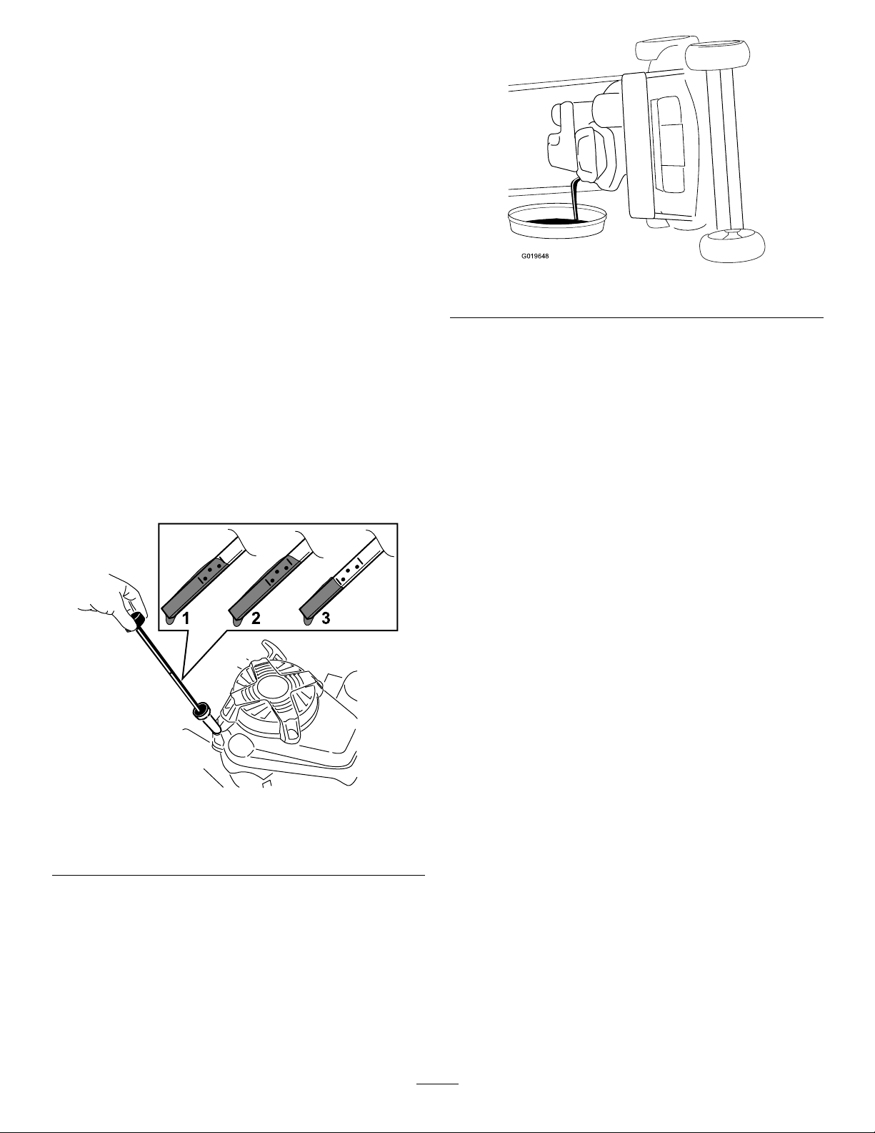
Vidangedel'huilemoteur
G019648
Périodicitédesentretiens:Aprèsles
5premièresheuresde
fonctionnement—Vidangezl'huile
moteursansleltreàhuile.
Toutesles50heures—Vidangezl'huilemoteur
(plusfréquemmentsivousutilisezlamachine
dansuneatmosphèrepoussiéreuse).
Remarque:Faitestournerlemoteurpendant
quelquesminutesavantlavidangepourréchauffer
l'huile.L'huilechaudes'écouleplusfacilementet
entraîneplusd'impuretés.
Capacitéd'huilemoteur:0,85L(29oz)avecltreà
huile;0,65L(22oz)sansltreàhuile
Viscositédel'huile:huiledétergenteSAE30ou
SAE10W-30
ClassedeserviceAPI:SJousupérieure
1.Amenezlamachinesurunsolplatethorizontal.
2.VoirConsignesdesécuritépendantl'entretien
(page19).
3.T ournezlebouchondanslesensantihoraireet
sortezlajauge(Figure28).
g019648
Figure29
5.Redressezlamachineaprèsavoirvidangé
l'huileusagée.
6.Versezlentementenviron3/4delacapacité
d'huilemoteurdansletubederemplissage
d'huile.
7.Attendezenviron3minutesquel'huilese
stabilisedanslemoteur.
8.Essuyezlajaugesurunchiffonpropre.
9.Insérezlajaugeaufonddugoulotde
remplissage,puisressortez-la.
Figure28
1.Niveaumax.3.Niveaumin.
2.Niveautropélevé
4.Inclinezlamachinesurlecôté(ltreàairen
haut)pourvidangerl'huileusagéeparletubede
remplissage(Figure29).
10.Vériezleniveaud'huileindiquéparlajauge
(Figure28).
•Sileniveaun'atteintpaslerepèreminimum
surlajauge,versezlentementunepetite
quantitéd'huiledansletubederemplissage,
patientez3minutesetrépétezlesopérations
8à10jusqu'àcequeleniveauatteignele
repèremaximum.
•Sileniveaud'huiledépasselerepère
maximumsurlajauge,vidangezl'excédent
d'huilejusqu'àcequeleniveausoit
redescenduaurepèremaximum.
g194742
Important:Sivousfaitestournerlemoteur
alorsqueleniveaud'huiledanslemoteur
esttropbasoutropélevé,vousrisquez
d'endommagerlemoteur.
11.Revissezlajaugefermementenplace.
12.Recyclezl'huileusagéecorrectement.
21
Page 94

Remplacementdultreà
g019650
1
huile
Périodicitédesentretiens:Toutesles100heures
1.Faitestournerlemoteurpourréchaufferl'huile.
2.Coupezlemoteuretattendezl'arrêtcompletde
touteslespiècesmobiles.
3.Débranchezleldelabougie.
4.Vidangezl'huilemoteur;voirVidangedel'huile
moteur(page21).
5.Placezunchiffonsousleltreàhuilepour
recueillirl'huilequipeuts'écoulerlorsdela
déposedultre.
6.Déposezleltreàhuile(Figure30).
Remarque:Assurez-vousquelejointdultre
àhuiles'enlèveenmêmetempsqueleltre.
8.Vissezleltreneufjusqu'àcequelejoint
rencontrelabasedultre,puisserrez-leàla
mainde2/3detoursupplémentaire.
9.Versezdel'huilefraîchedanslecartermoteur
jusqu'aurepèremaximumsurlajauge;voir
Vidangedel'huilemoteur(page21).
10.Branchezleldelabougie.
11.Faitestournerlemoteurpendantenviron
3minutes.
12.Arrêtezlemoteur,attendezl'arrêtcompletde
touteslespiècesmobilesetrecherchezles
fuitesd'huileéventuellesautourdultre.
13.Ajoutezdel'huilepourcompenserl'huilequi
setrouvedansleltre;voirVidangedel'huile
moteur(page21).
14.Recyclezleltreàhuileusagéconformément
àlaréglementationlocaleenmatière
d'environnement.
Entretiendelabougie
Figure30
1.Filtreàhuile
7.Aveclesdoigts,appliquezdel'huilesurlejoint
dultreneuf(Figure31).
Périodicitédesentretiens:Toutesles100heures
UtilisezunebougieNGKBPR5ESouéquivalente.
1.Coupezlemoteuretattendezl'arrêtcompletde
touteslespiècesmobiles.
2.Débranchezleldelabougie.
3.Nettoyezlasurfaceautourdelabougie.
4.Retirezlabougiedelaculasse.
Important:Remplacezlabougiesielle
g019650
estssurée,calaminéeouencrassée.
Nenettoyezpaslesélectrodes,cardes
particulesrisquentdetomberdansla
culasseetd'endommagerlemoteur.
5.Réglezl'écartementdesélectrodesà0,76mm
(0,030po);voirFigure32.
g000533
Figure32
g002805
Figure31
1.Joint
1.Becisolantd'électrode
centrale
2.Électrodelatérale
22
3.Écartement(pasà
l'échelle)
Page 95

6.Posezlabougieetlejoint.
g019650
1
g019924
1
2
7.Serrezlabougieà23N∙m(17pi-lb).
8.Branchezleldelabougie.
Contrôledel'étatdes courroies
Périodicitédesentretiens:Toutesles50heures
1.Coupezlemoteuretattendezl'arrêtcompletde
touteslespiècesmobiles.
2.Déposezlecouvercledecourroie(Figure9)en
retirantles4boulonsquilexeaucarterdela
machine.
3.Vériezsilescourroiessontssurées,
présententdesbordseflochés,destracesde
brûluresoud'autresdégâts.
4.Remplaceztouteslescourroiesendommagées.
5.Vousdevezréglerlacourroied'entraînement
deslamessivouslaremplacez.VoirEntretien
dusystèmed'entraînementdeslames(page
23).
6.Fixezlecouvercledelacourroieavecles
4boulonsretirésàl'opération2.
5.Ouvrezlerobinetd'arrivéedecarburant
etvidangezcomplètementleréservoiretla
conduitedecarburantdansunbidonhomologué.
6.Déposezleréservoirdecarburantdela
machine.
7.Versezunepetitequantitédecarburantdans
leréservoir,agitezleliquideàl'intérieuret
versez-ledansunbidonhomologué.
8.Reposezleréservoirdecarburantetlaconduite
decarburant.
Remplacementdultreà
carburant
Périodicitédesentretiens:Toutesles100heures
1.Coupezlemoteuretattendezl'arrêtcompletde
touteslespiècesmobiles.
2.Débranchezleldelabougie.
3.Fermezlerobinetd'arrivéedecarburant(Figure
33).
Vidangeduréservoirde
carburantetnettoyagedu
ltreàcarburant
Périodicitédesentretiens:Toutesles50
heures—Examinezleexible
d'alimentationetremplacez-leau
besoin.
Toutesles100heures—Nettoyezleltredu
réservoirdecarburant.
Unefoisparanouavantleremisage—Vidangez
leréservoirdecarburantavantlesréparations
quilenécessitentetavantderemiserla
machine.
Remarque:Leltreàcarburant(crépine)estsituéà
l'intérieurduréservoirdecarburant,auniveaudela
sortie.Celtrefaitpartieduréservoirdecarburantet
nepeutpasêtredéposé.
1.Coupezlemoteuretlaissez-lerefroidir.
Important:Nevidangezlecarburantque
lorsquelemoteurestfroid.
2.Débranchezleldelabougie.
3.Fermezlerobinetd'arrivéedecarburant.
4.Débranchezlaconduited'alimentationen
desserrantlecollierauniveauducarburateur.
g019924
Figure33
1.Filtreàcarburant2.Robinetd'arrivéede
carburant
4.Déposezleltreàcarburant(Figure33)dela
conduitedecarburantendesserrantlescolliers
quientourentleltre.
5.Posezunltreàcarburantneufdanslaconduite
decarburantàl'aidedescolliersretirésà
l'opération4.
Entretiendusystème d'entraînementdeslames
Périodicitédesentretiens:Aprèsles5premières
heuresdefonctionnement
23
Page 96

Toutesles50heures—Enlevezlesdébris
aggloméréssouslecouvercledelacourroie.
Toutesles50heures—Effectuezl'entretiendu
systèmed'entraînementdeslames.
1.Desserrezles2vissurlepanneaud'accèsau
couvercledecourroieetdéposezlepanneau
(Figure34).
Figure34
1.Ressortdetensiondela
courroie
2.Boulonderéglage6.Paroi
3.Espace
4.Écrouderéglage
2.Enlevezlesdébrisquisetrouventàl'intérieur
ducouvercledecourroieetautourdespiècesà
labrosseouàl'aircomprimé.
3.Placezunejauged'épaisseurentre0,13et
0,76mm(0,005et0,03po)contrelaparoiet
faites-laglisserverslebasderrièreleressortde
tensiondelacourroie;voirFigure35.
5.Courroied'entraînement
deslames
7.Couvercledecourroie
8.Panneaud'accèsau
couvercledecourroie
d'endommagerlacourroied'entraînement
deslames.
4.Posezlepanneaud'accèsaucouverclede
courroie.
Entretiendeslames
Périodicitédesentretiens:Àchaqueutilisationou
unefoisparjour
Important:Vousaurezbesoind'uneclé
dynamométriquepourmonterleslames
correctement.Sivousn'enpossédezpas
ousivousnevoussentezpascapable
d'effectuercetteprocédure,adressez-vousàun
dépositaire-réparateuragréé.
Chaquefoisqueleréservoirdecarburantestvide,
vériezl'affûtageetl'étatdeslames(usureou
dommages);voirContrôledeslames(page25).Sila
lameestémousséeouébréchée,faites-laaiguiserou
remplacez-la.Remplacezimmédiatementleslames
usées,faussées,endommagéesoufêléespardes
g208925
lamesTorod'origine.
DANGER
Unelameuséeouendommagéepeutsebriser
etprojeterlemorceaucasséversl'utilisateur
oudespersonnesàproximité,etleuriniger
desblessuresgravesoumortelles.
•Vériezl'étatetl'usuredeslames
périodiquement.
•Remplacezleslamesuséesou
endommagées.
Remarque:Utilisezdeslamesbienaiguiséesdurant
toutelasaisondetonte,pourobtenirunecoupe
nettesansarrachernidéchiqueterlesbrinsd'herbe.
L'herbearrachéeoudéchiquetéebrunitsurlesbords,
sacroissanceralentitetelledevientplussensible
auxmaladies.
decal116-8528
Figure35
Remarque:Siunespaceestvisibleentrela
jaugeetleressort,serrezleboulonetl'écrou
deréglagejusqu'àcequelajauged'épaisseur
puisseàpeinepasserdansl'espace(Figure34).
Important:Neserrezpasleboulonde
réglageexcessivement.Celarisquerait
Préparationàl'entretiendeslames
Basculezlamachinesurlecôté,ltreàairenhaut,
jusqu'àcequelapartiesupérieureduguidonsoit
poséesurlesol.
ATTENTION
Leslamessonttranchantesetvouspouvez
vousblessergravementàleurcontact.
•Débranchezleldelabougie.
•Portezdesgantspoureffectuerl'entretien
deslames.
24
Page 97

Contrôledeslames
g017223
B
B
2
1
3
g016532
Détectiondeslamesfaussées
Périodicitédesentretiens:Àchaqueutilisationou
unefoisparjour
1.Examinezletranchantdeslames(Figure36).
Siellessontémousséesouprésententdes
indentations,déposezleslamesetaffûtez-les
ouremplacez-les.
Figure36
1.Partierelevée
2.Tranchant4.Fissure
2.Inspectezleslames,surtoutlapartierelevée
(Figure42).Remplacezimmédiatementtoute
lameendommagée,uséeouquiprésenteune
entaille(Figure36).
3.Usure/formationd'une
entaille
1.Faitestournerleslamesjusqu'àcequ'elles
soientdanslapositionillustréeàlaFigure37.
g017223
g016532
Figure37
1.Avantdutablierdecoupe3.Mesurezladistanceentre
letranchantetunesurface
planeetlisse
2.MesurerauxpointsAetB
DANGER
Siunelamedevienttropusée,une
entailleseformeentrelapartierelevéeet
lapartieplane.Lalamepourraitsebriser
etunmorceauêtreprojetédudessous
2.Mesurezladistanceentreunesurfaceplaneet
letranchantauxpointsAetB,(Figure37),et
notezlesdeuxdimensions.
3.Faitestournerlespointesdesortequeleurs
extrémitésopposéessoientauxpointsAetB.
delamachine,vousblessantgravement
ouunepersonneàproximité.
4.Répétezlesmesuresdel'opération2et
notez-les.
•Vériezl'étatetl'usuredeslames
périodiquement.
•N'essayezjamaisderedresserune
lamefausséeoudesouderunelame
Remarque:Siladifférenceentreles
dimensionsAetBobtenuesauxopérations2
et4dépasse3mm(⅛po),remplacezleslames;
voirDéposedeslames(page26).
briséeoufendue.
•Recherchezleslamesfaussées;voir
Détectiondeslamesfaussées(page
25).
ATTENTION
Unelamefausséeouendommagée
peutsebriseretprojeterlemorceau
cassédansvotredirectionoucellede
personnesàproximité,etcauserdes
blessuresgravesoumortelles.
•Remplaceztoujoursunelamefaussée
ouendommagéeparuneneuve.
•Necréezjamaisd'indentationsdans
lesbordsouàlasurfacedeslames,
parexempleenleslimant.
25
Page 98

Déposedeslames
G016530
1
2
3
4
g016537
Posedeslames
Remplacezleslamessiellesheurtentunobstacle,
etsiellessontdéséquilibrées,fausséesouusées.
UtiliseztoujoursdeslamesderechangeTorod'origine.
1.Utilisezunblocdeboispourimmobiliserchaque
lameettournezleboulondelamedanslesens
antihoraire,commemontréàlaFigure38.
Figure38
2.Déposezchaquelamecommemontréàla
Figure39.
ATTENTION
Deslamesmalinstalléesrisquent
d'endommagerlamachineoudeblesser
l'utilisateuroutoutepersonneàproximité.
Installezleslamesconformémentaux
instructions.
1.Posezlapremièrelamedesortequ'ellesoit
horizontale,avectouteslesxations,comme
montréàlaFigure39.
Remarque:Serrezleboulonàlamain.
Important:Lesextrémitésrelevées
deslamesdoiventêtredirigéesversla
machine.Assurez-vousquelespartiesen
reliefdechaquedispositifd'entraînement
s'emboîtentdanslescreuxdelatêtede
l'axecorrespondant,etquelesgoupilles
situéesdel'autrecôtédechaquedispositif
g016527
d'entraînements'emboîtentdanslestrous
delalamecorrespondante.
2.Immobilisezchaquelameàl'aided'uneplanche
ettournezleboulondelamedanslesens
horaireaumoyend'uneclédynamométrique
commemontréàlaFigure40;serrezchaque
boulondelameà82N∙m(60pi-lb).
Figure39
1.Axe(2)3.Lame(2)
2.Dispositifd'entraînement
deslames(2)
3.Contrôlezl'étatetl'usuredesgoupillessurles
dispositifsd'entraînementdeslames.
4.Boulondelame(2)
g016530
g016537
Figure40
Important:Unboulonvisséà82N·m
(60pi-lb)esttrèsserré.Appuyezdetout
votrepoidssurlacléetserrezsolidementle
26
Page 99

boulon.Ilestpratiquementimpossiblede
1
G016536
tropserrerceboulon.
3.Faitestournerlalameinstalléed'unquartde
tourjusqu'àlaverticale,puismontezl'autre
lamedelamêmemanièrequelapremière(voir
l'opération1).
Remarque:Leslamesdevraientêtre
perpendiculairesetformerun«T»renversé,
commemontréàlaFigure41.
Remarque:Conservezlaprotectiondela
courroiedeBBCetlesxationspourlarepose.
g208922
Figure42
Figure41
1.Lame(2)
4.Serrezladeuxièmelame;voirl'opération2.
5.Faitestournerleslamesàlamaind'untour
complet(360°)pourvousassurerqu'ellesne
setouchentpas.
Remarque:Sileslamessetouchent,c'est
qu'ellesnesontpascorrectementinstallées.
Recommencezlesopérations1à3jusqu'àce
queleslamesnesetouchentplus.
Remplacementdela courroied'entraînement deslames
Remplacezlacourroied'entraînementdeslamesau
besoin.
1.CourroieduBBC
g016536
2.Protectiondecourroiedu
BBC
6.RetirezlacourroiedeBBCdelapoulieavant
gauche.
7.Desserrezleboulonderéglage(Figure34).
8.Déposezlapouliedetensionxeetlesxations
(Figure43).
Remarque:Conservezlapouliedetensionet
lesxationspourlarepose.
1.Coupezlemoteuretattendezl'arrêtcompletde
touteslespiècesmobiles.
2.Débranchezleldelabougie.
3.Déposezlecouvercledecourroie(Figure9)en
retirantles4boulonsquilexeaucarterdela
machine.
Remarque:Conservezlesboulonspourxer
Figure43
LapouliedetensiondeBBCn'estpasreprésentéepour
plusdeclarté
g208924
lecouvercledecourroieaucarterdelamachine.
4.Enlevezlesdébrisaggloméréssouslecouvercle
delacourroie.
1.Troudanslecarter
2.Troudepignondroit4.Troudepignongauche
3.Pouliedetensionxe
5.DéposezlaprotectiondecourroiedeBBCainsi
quelesxations.
9.Déposezlacourroied'entraînementdeslames.
27
Page 100

10.Alignezlestrousdespignonsgaucheetdroitsur
lestrousducarter,commemontréàlaFigure
43.
Remarque:Maintenezlespignonsenplace
avecunetigeouuntournevis.
11.Lorsquelespignonssontbloquésenplace,
installezlacourroied'entraînementdeslameset
lapouliedetensionxe.
Remarque:Vériezquelesdentssontbien
engagéesdanslespignons.
12.Réglezlatensiondelacourroiecomme
recommandés;voirEntretiendusystème
d'entraînementdeslames(page23).
13.Retirezlatigeouletournevisdespignons.
14.Vériezqueleslamessontcorrectement
alignéessouslecarter;voirEntretiendeslames
(page24).
15.PosezlacourroiedeBBCetsaprotection,ainsi
quelesxations.
16.Fixezlecouvercledelacourroieavecles
4boulonsretirésàl'opération3.
17.Branchezleldelabougie.
18.Vériezlefonctionnementdelabarrede
commandeetdudébrayagedufreindeslames
(BBC).
Remplacementdela
Figure44
1.CourroieduBBC
8.DégagezlacourroieduBBCdelapouliede
tambourdefrein,puisdéposezlacourroiede
lamachine.
2.Protectiondecourroiedu
BBC
Remarque:Tenezunedeslamesavecun
gantouunchiffonettournezl'axedelalame
pourfaciliterladéposedelacourroiedeBBC.
9.PourinstallerunecourroiedeBBCneuve,
inversezlesopérationsci-dessus.
10.RéglezlecâbledeBBC;voirRéglageducâble
dufreindeslames(page28).
g208922
courroiededébrayagedu
freindeslames(BBC)
Périodicitédesentretiens:Toutesles250heures
1.Coupezlemoteuretattendezl'arrêtcompletde
touteslespiècesmobiles.
2.Débranchezleldelabougie.
3.Enlevezles4boulonsquixentlecouverclede
courroieàlamachine.
Remarque:Conservezlesboulonspourxer
lecouvercledecourroieaucarterdelamachine.
4.Déposezlecouvercledecourroie.
5.Enlevezlesdébrisaggloméréssouslecouvercle
delacourroie.
6.Déposezlacourroiedetransmission;voir
Remplacementdelacourroiedetransmission
(page30).
7.DéposezlaprotectiondelacourroieduBBC
(Figure44).
Remarque:Conservezlesxationspour
remonterlacourroieduBBCultérieurement.
Réglageducâbledufrein deslames
Réglezlecâbledufreindeslameschaquefoisque
vousinstallezuncâbleneufouquevousremplacezla
courroiededébrayagedufreindeslames(BBC).
1.Coupezlemoteuretattendezl'arrêtcompletde
touteslespiècesmobiles.
2.Débranchezleldelabougie.
3.Déposezlecouvercledecourroie(Figure9)en
retirantles4boulonsquilexeaucarterdela
machine.
Remarque:Conservezlesboulonspourxer
lecouvercledecourroieaucarterdelamachine.
4.Enlevezlesdébrisaggloméréssouslecouvercle
delacourroie.
5.Desserrezlavisduserre-câble(Figure45).
28
 Loading...