

Page 1
TimeMaster30inLawnMower
ModelNo.21199—SerialNo.403600000andUp
ModelNo.21 199HD—SerialNo.404314000andUp
ModelNo.21200—SerialNo.403600000andUp
FormNo.3423-195RevA
Operator'sManual
Introduction
Thisrotary-blade,walk-behindlawnmowerisintended
tobeusedbyresidentialhomeowners.Itisdesigned
primarilyforcuttinggrassonwell-maintainedlawns
onresidentialproperties.Itisnotdesignedforcutting
brushorforagriculturaluses.
Readthisinformationcarefullytolearnhowtooperate
andmaintainyourproductproperlyandtoavoid
injuryandproductdamage.Youareresponsiblefor
operatingtheproductproperlyandsafely.
YoumaycontactT orodirectlyatwww.Toro.comfor
productandaccessoryinformation,helpndinga
dealer,ortoregisteryourproduct.
Wheneveryouneedservice,genuineToroparts,or
additionalinformation,contactanAuthorizedService
DealerorToroCustomerServiceandhavethemodel
andserialnumbersofyourproductready .Figure1
identiesthelocationofthemodelandserialnumbers
ontheproduct.Writetheproductmodelandserial
numbersinthespaceprovided.
Important:Withyourmobiledevice,youcan
scantheQRcodeontheserialnumberdecal(if
equipped)toaccesswarranty,parts,andother
productinformation.
seriousinjuryordeathifyoudonotfollowthe
recommendedprecautions.
g000502
Figure2
Safety-alertsymbol
Thismanualuses2wordstohighlightinformation.
Importantcallsattentiontospecialmechanical
informationandNoteemphasizesgeneralinformation
worthyofspecialattention.
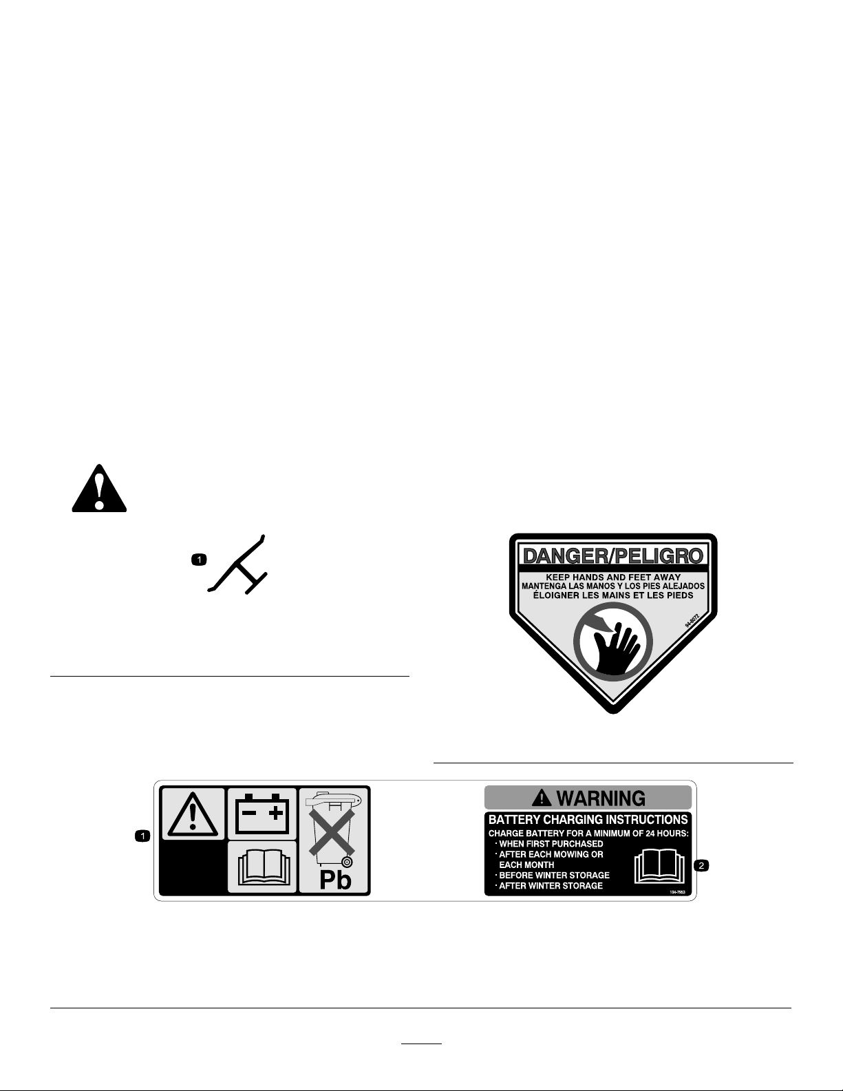
ItisaviolationofCaliforniaPublicResourceCode
Section4442or4443touseoroperatetheengineon
anyforest-covered,brush-covered,orgrass-covered
landunlesstheengineisequippedwithaspark
arrester,asdenedinSection4442,maintainedin
effectiveworkingorderortheengineisconstructed,
equipped,andmaintainedforthepreventionofre.
TheenclosedEngineOwner'sManualis
suppliedforinformationregardingtheUS
EnvironmentalProtectionAgency(EPA)and
theCaliforniaEmissionControlRegulationof
emissionsystems,maintenance,andwarranty.
Replacementsmaybeorderedthroughtheengine
manufacturer.
Figure1
1.Modelandserialnumberlocation
ModelNo.
SerialNo.
Thismanualidentiespotentialhazardsandhas
safetymessagesidentiedbythesafety-alertsymbol
(Figure2),whichsignalsahazardthatmaycause
©2018—TheT oro®Company
8111LyndaleAvenueSouth
Bloomington,MN55420
Registeratwww.Toro.com.
GrossorNetTorque:Thegrossornettorque
ofthisenginewaslaboratoryratedbytheengine
g226622
manufacturerinaccordancewiththeSocietyof
AutomotiveEngineers(SAE)J1940orJ2723.As
conguredtomeetsafety,emission,andoperating
requirements,theactualenginetorqueonthisclass
ofmowerwillbesignicantlylower.Pleasereferto
theenginemanufacturer’sinformationincludedwith
themachine.
OriginalInstructions(EN)
PrintedinMexico
AllRightsReserved
*3423-195*A
Page 2

WARNING
CALIFORNIA
Proposition65Warning
Theengineexhaustfromthisproduct
containschemicalsknowntotheStateof
Californiatocausecancer,birthdefects,
orotherreproductiveharm.
Batteryposts,terminals,andrelated
accessoriescontainleadandlead
compounds,chemicalsknownto
theStateofCaliforniatocause
cancerandreproductiveharm.Wash
handsafterhandling.
Useofthisproductmaycauseexposure
tochemicalsknowntotheStateof
Californiatocausecancer,birthdefects,
orotherreproductiveharm.
AfterOperation....................................................22
AfterOperationSafety......................................22
CleaningundertheMachine.............................22
Maintenance...........................................................24
RecommendedMaintenanceSchedule(s)...........24
MaintenanceSafety..........................................24
PreparingforMaintenance...............................24
ServicingtheAirFilter.......................................25
ChangingtheEngineOil...................................25
ChargingtheBattery.........................................26
ReplacingtheFuse...........................................27
ReplacingtheBattery.......................................27
AdjustingtheSelf-PropelDrive.........................28
ServicingtheBlade-DriveSystem.....................28
ServicingtheBlades.........................................29
CheckingforBentBlades.................................30
RemovingtheBlades........................................31
InstallingtheBlades..........................................31
Storage...................................................................32
GeneralInformation..........................................32
PreparingtheFuelSystem...............................32
PreparingtheEngine........................................33
RemovingtheMachinefromStorage................33
Contents
Introduction...............................................................1
Safety.......................................................................3
GeneralSafety...................................................3
SafetyandInstructionalDecals..........................3
Setup........................................................................6
1AssemblingandUnfoldingtheHandle..............6
2InstallingtheBlade-ControlBar........................6
3FillingtheEnginewithOil.................................8
4AssemblingtheGrassBag...............................8
5ChargingtheBattery........................................9
ProductOverview.....................................................9
Operation................................................................10
BeforeOperation.................................................10
BeforeOperationSafety...................................10
FillingtheFuelTank...........................................11
CheckingtheEngine-OilLevel..........................12
AdjustingtheHandleHeight.............................13
AdjustingtheCuttingHeight.............................14
DuringOperation.................................................14
DuringOperationSafety...................................14
StartingtheEngine...........................................15
UsingtheSelf-PropelDrive...............................17
ShuttingOfftheEngine.....................................17
EngagingtheBlades.........................................18
DisengagingtheBlades....................................18
CheckingtheBlade-StopSystem
Operation......................................................19
RecyclingtheClippings....................................19
BaggingtheClippings.......................................20
Side-DischargingtheClippings.........................20
OperatingTips.................................................21
2
Page 3
Safety
Thismachinehasbeendesignedinaccordancewith
ANSIB71.1-2012.
GeneralSafety
Thisproductiscapableofamputatinghandsand
feetandofthrowingobjects.Alwaysfollowallsafety
instructionstoavoidseriouspersonalinjury .
•Donotoperatethemachinewithoutallguards
andothersafetyprotectivedevicesinplaceand
workingonthemachine.
•Keepbystandersandchildrenasafedistance
awayfromthemachine.Donotallowchildrento
operatethemachine.Allowonlypeoplewhoare
responsible,trained,familiarwiththeinstructions,
andphysicallycapabletooperatethemachine.
•Stopthemachineandshutofftheenginebefore
servicing,fueling,oruncloggingthemachine.
Usingthisproductforpurposesotherthanitsintended
usecouldprovedangeroustoyouandbystanders.
•Read,understand,andfollowtheinstructions
andwarningsinthisOperator’sManualandon
themachineandattachmentsbeforestartingthe
engine.
•Donotputyourhandsorfeetnearmovingpartsof
orunderthemachine.Keepclearofanydischarge
opening.
SafetyandInstructionalDecals
Safetydecalsandinstructionsareeasilyvisibletotheoperatorandarelocatednearanyarea
ofpotentialdanger.Replaceanydecalthatisdamagedormissing.
decaloemmarkt
Manufacturer'sMark
Improperlyusingormaintainingthismachinecan
resultininjury.T oreducethepotentialforinjury,
complywiththesesafetyinstructionsandalwayspay
attentiontothesafety-alertsymbol,whichmeans
Caution,Warning,orDanger—personalsafety
instruction.Failuretocomplywiththeseinstructions
mayresultinpersonalinjuryordeath.
Youcanndadditionalsafetyinformationwhere
neededthroughoutthismanual.
1.Thismarkindicatesthatthebladeisidentiedasapart
fromtheoriginalmachinemanufacturer .
104-7953
Electric-StartModelOnly
1.Warning—readtheOperator'sManualforinformationonchargingthebattery;containslead;donotdiscard.
2.ReadtheOperator'sManual.
decal94-8072
94-8072
decal104-7953
3
Page 4
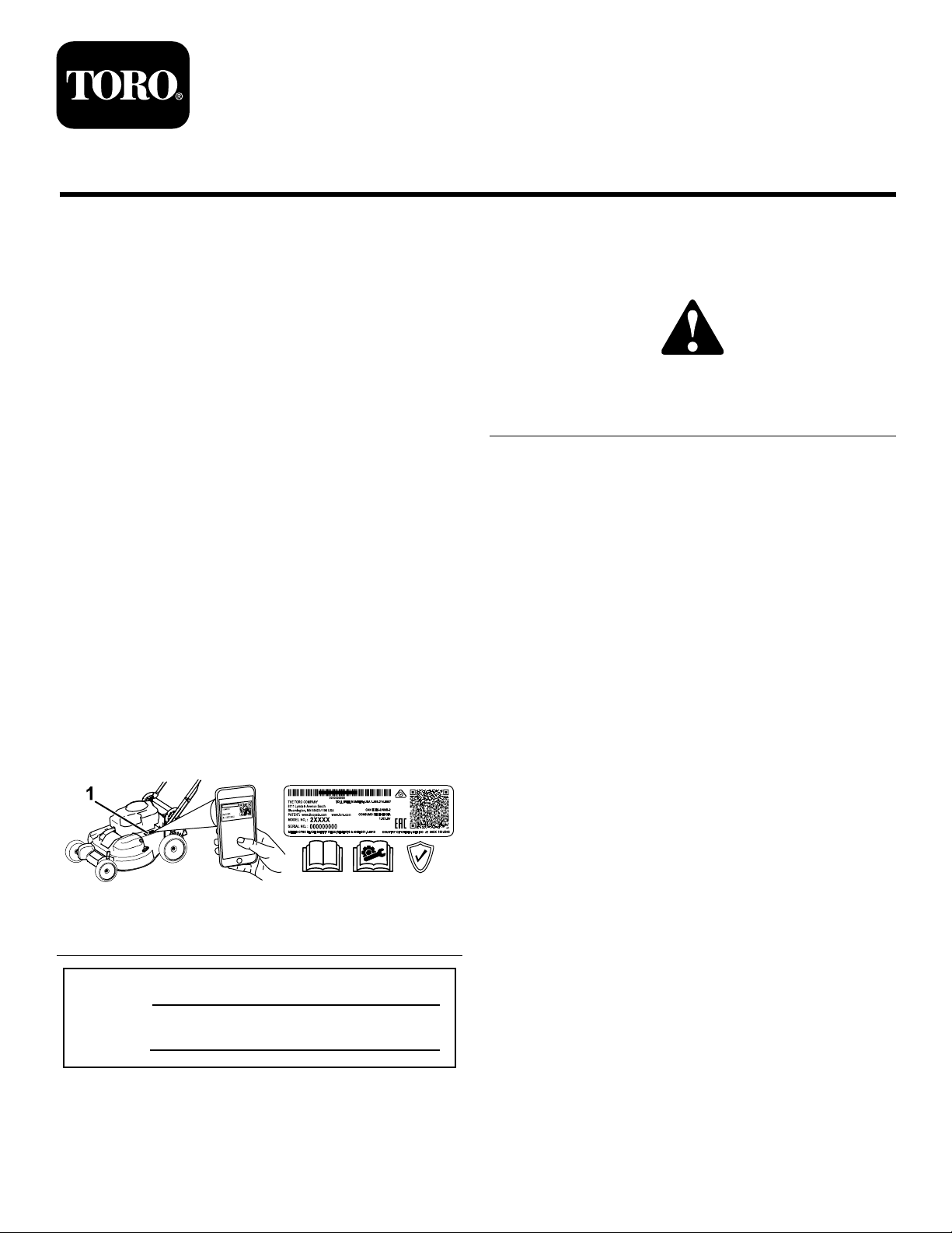
108-9751
Electric-StartModelOnly
1.Engine—stop(shutoff)
2.Engine—run
3.Engine—start
133-8062
120-9570
1.Warning—stayawayfrommovingparts;keepallguards
andshieldsinplace.
decal108-9751
decal131-4514b
131-4514
1.Warning—readtheOperator'sManual.
2.Cutting/dismembermenthazardofhandorfoot,mower
blade—stayawayfrommovingparts;keepallguardsand
shieldsinplace.
3.Cutting/dismembermenthazardofhandorfoot,mower
blade—disconnectthespark-plugwireandreadthe
instructionsbeforeservicingorperformingmaintenance.
4.Thrownobjecthazard—keepbystandersasafedistance
awayfromthemachine;shutofftheenginebeforeleaving
decal133-8062
decal120-9570
theoperatingposition;pickupanydebrisbeforemowing.
5.Cutting/dismembermenthazardofhandorfoot,mower
blade—donotoperateupanddownslopes;operatesideto
sideonslopes;lookbehindyouwhenbackingup.
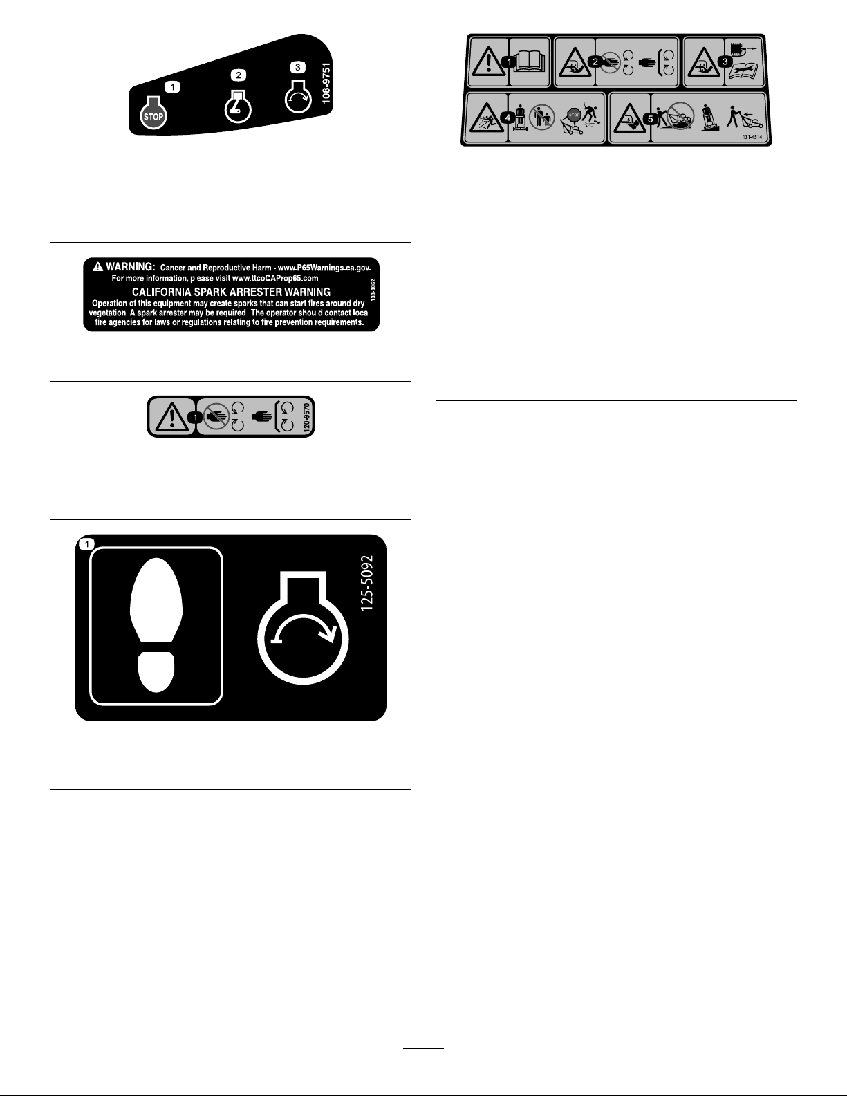
125-5092
1.Steponthemowerhousingtostarttheengine.
decal125-5092
4
Page 5
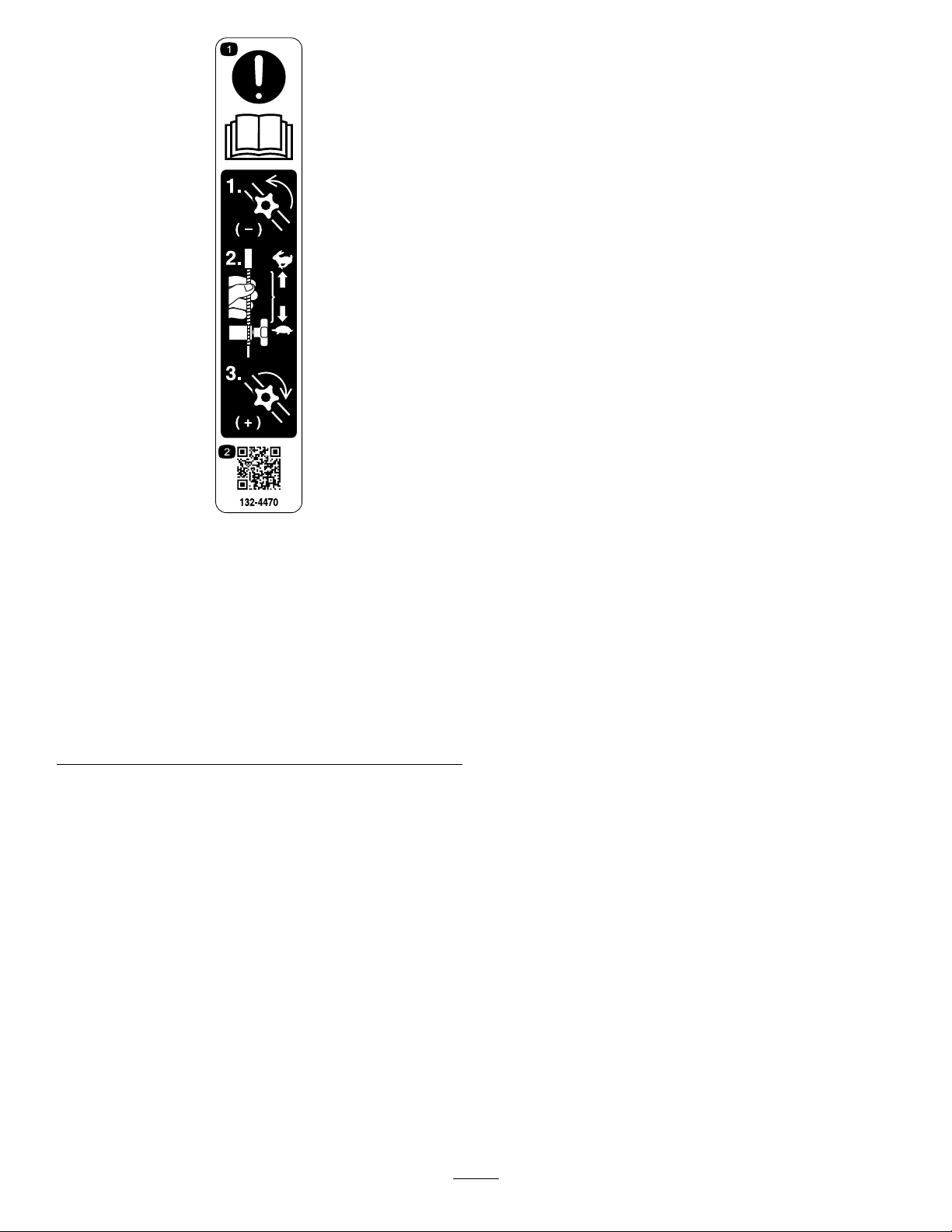
decal132-4470
132-4470
TractionAdjustment
1.Attention;readthe
Operator'sManual—1)
Loosentheknobbyturning
itcounterclockwise;2)Pull
thecable(s)awayfrom
theenginetodecrease
thetraction,orpushthe
cable(s)towardtheengine
toincreasethetraction;
3)Tightentheknobby
turningitclockwise.
2.ScantheQRcodefor
moreinformationon
tractionadjustment.
5
Page 6

Setup
Important:Removeanddiscardtheprotectiveplasticsheetthatcoverstheengineandanyother
plasticorwrappingonthemachine.
Important:Topreventaccidentalstarting,donotinsertthekeyintotheelectric-startignition(if
equipped)untilyouarereadytostarttheengine.
1
AssemblingandUnfoldingtheHandle
NoPartsRequired
Procedure
WARNING
Assemblingandunfoldingthehandleimproperlycandamagethecables,causinganunsafe
operatingcondition.
•Donotdamagethecableswhenunfoldingthehandle.
•Ifacableisdamaged,contactanAuthorizedServiceDealer.
Figure3
g224528
6
Page 7
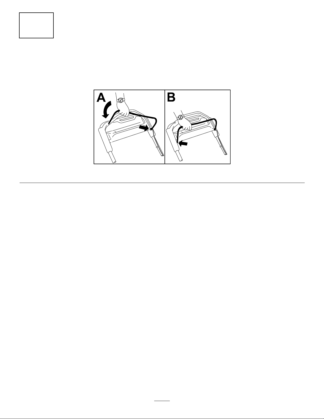
2
InstallingtheBlade-ControlBar
NoPartsRequired
Procedure
g225133
Figure4
7
Page 8
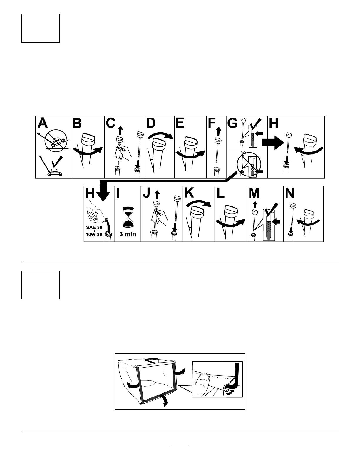
3
FillingtheEnginewithOil
NoPartsRequired
Procedure
Important:Yourmachinedoesnotcomewithoilintheengine,butitdoescomewithabottleofoil.
Beforestartingtheengine,lltheenginewithoil.
4
AssemblingtheGrassBag
NoPartsRequired
Procedure
g222533
Figure5
g230447
Figure6
8
Page 9
5
ChargingtheBattery
NoPartsRequired
Procedure
Electric-StartModelOnly
RefertoChargingtheBattery(page26).
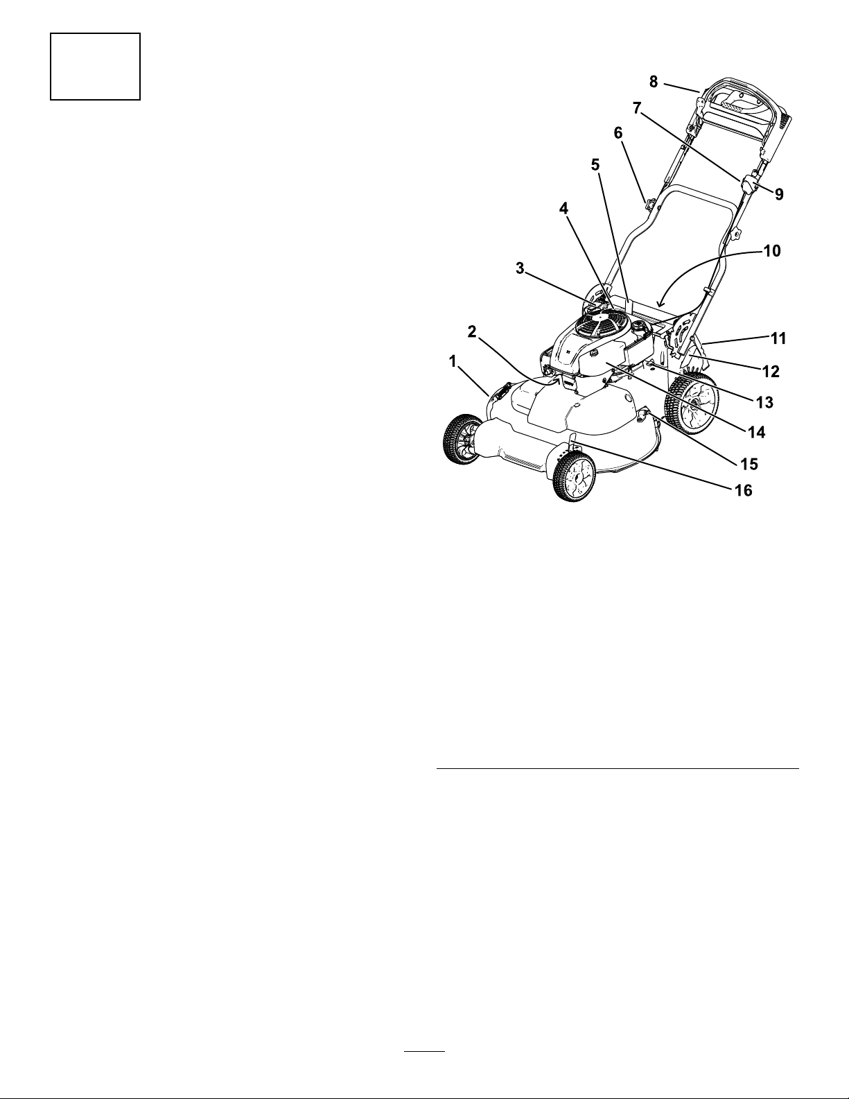
ProductOverview
Figure7
1.Side-dischargedeector
2.Sparkplug10.Battery(electric-start
3.Recoil-starthandle11.Reardoor
4.Oilll/dipstick
5.Handle-locklever13.Fuse
6.Handleknob(2)14.Airlter
7.Adjustmentknobforthe
self-propeldrive
8.Upperhandle16.Frontcutting-heightlever
9.Ignitionswitch
(electric-startmodelonly)
ortoggleswitch(standard
modelonly)
modelonly;notshown)
12.Rearcutting-heightlever
15.Washoutport
g191969
9
Page 10
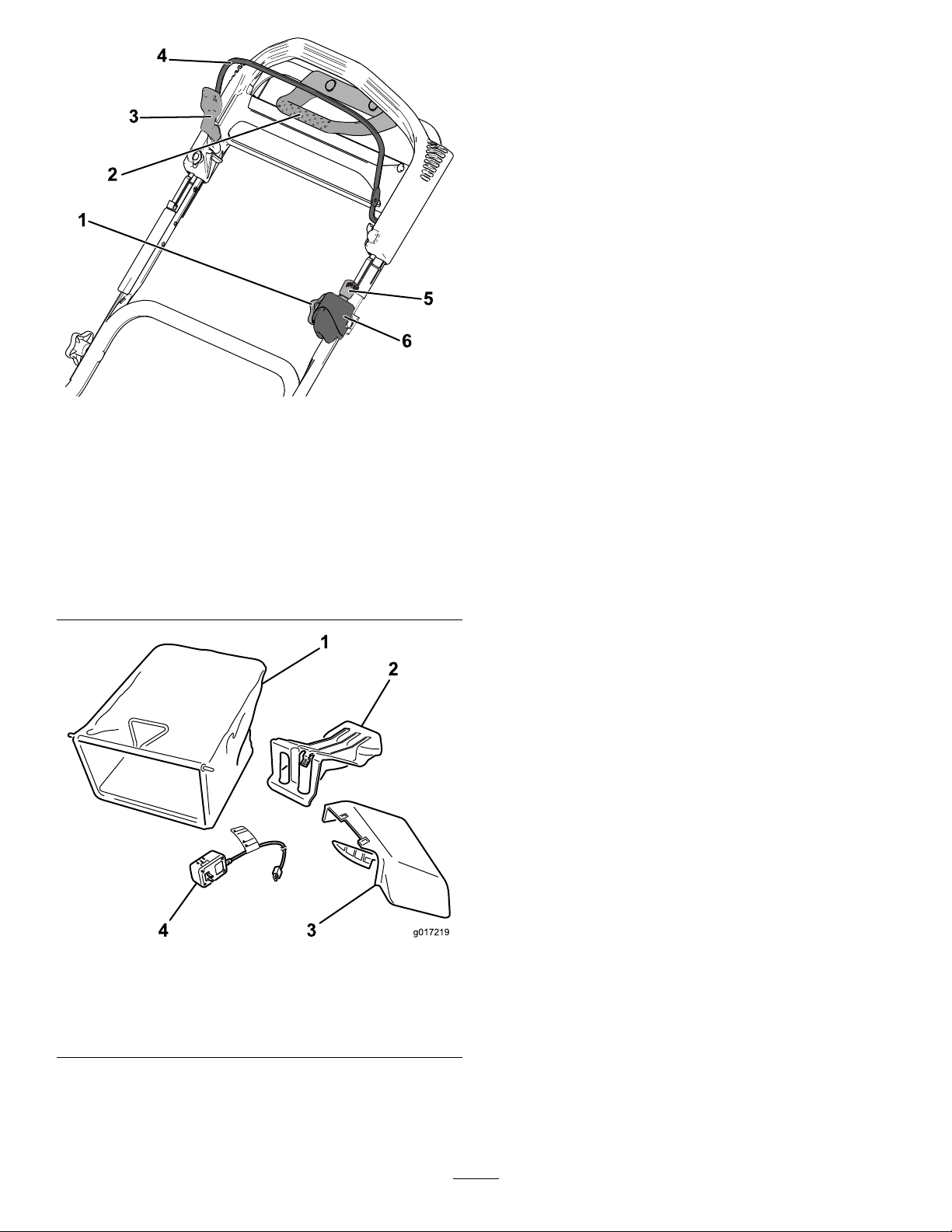
Figure8
Upperhandle
1.Adjustmentknobforthe
self-propeldrive
2.Traction-assisthandle
3.Blade-control-barlock6.Ignitionswitch
4.Blade-controlbar
5.Ignitionkey(electric-start
modelonly)
(electric-startmodelonly)
ortoggleswitch(standard
modelonly)
Operation
Note:Determinetheleftandrightsidesofthe
machinefromthenormaloperatingposition.
BeforeOperation
BeforeOperationSafety
GeneralSafety
•Becomefamiliarwiththesafeoperationofthe
equipment,operatorcontrols,andsafetysigns.
•Checkthatallguardsandsafetydevices,suchas
deectorsand/orgrasscatcher,areinplaceand
g191981
workingproperly.
•Alwaysinspectthemachinetoensurethatthe
blades,bladebolts,andcuttingassemblyarenot
wornordamaged.
•Inspecttheareawhereyouwillusethemachine,
andremoveallobjectsthatcouldinterferewith
theoperationofthemachineorthatthemachine
couldthrow.
•Adjustingthecuttingheightmaybringyouinto
contactwiththemovingblade,causingserious
injury.
Figure9
1.Grassbag3.Side-dischargechute
2.Rear-dischargeplug
(installed)
4.Batterycharger
(electric-startmodelonly)
–Shutofftheengine,removetheignitionkey
(electric-startmodelonly),andwaitforall
movingpartstostop.
–Donotputyourngersunderthehousing
whenadjustingthecuttingheight.
FuelSafety
•Fuelisextremelyammableandhighlyexplosive.
Areorexplosionfromfuelcanburnyouand
othersandcandamageproperty.
–Topreventastaticchargefromignitingthefuel,
placethecontainerand/ormachinedirectlyon
thegroundbeforelling,notinavehicleoron
anobject.
g017219
–Fillthefueltankoutdoors,inanopenarea,
whentheengineiscold.Wipeupanyfuelthat
spills.
–Donothandlefuelwhensmokingoraroundan
openameorsparks.
–Donotremovethefuelcaporaddfueltothe
tankwhiletheengineisrunningorhot.
–Ifyouspillfuel,donotattempttostartthe
engine.Avoidcreatingasourceofignitionuntil
thefuelvaporshavedissipated.
10
Page 11

–Storefuelinanapprovedcontainerandkeep
itoutofthereachofchildren.
•Fuelisharmfulorfatalifswallowed.Long-term
exposuretovaporscancauseseriousinjuryand
illness.
–Avoidprolongedbreathingofvapors.
–Keepyourhandsandfaceawayfromthe
nozzleandthefuel-tankopening.
–Keepfuelawayfromyoureyesandskin.
FillingtheFuelTank
•Forbestresults,useonlyclean,fresh,unleaded
gasolinewithanoctaneratingof87orhigher
((R+M)/2ratingmethod).
•Oxygenatedfuelwithupto10%ethanolor15%
MTBEbyvolumeisacceptable.
•Donotuseethanolblendsofgasoline,such
asE15orE85,withmorethan10%ethanolby
volume.Performanceproblemsand/orengine
damagemayresult,whichmaynotbecovered
underthewarranty.
•Donotusegasolinecontainingmethanol.
•Donotstorefueleitherinthefueltankorinfuel
containersoverthewinterunlessfuelstabilizer
hasbeenaddedtothefuel.
•Donotaddoiltogasoline.
Fillthefueltankwithfreshunleadedregulargasoline
fromamajorname-brandservicestation.
Important:T oreducestartingproblems,add
fuelstabilizertothegasolineallseason.Mixthe
stabilizerwithgasolinelessthan30daysold.
g234916
Figure10
2.Installthefuel-tankcapandtightenitsecurely
byhand.
1.Cleanaroundthefuel-tankcapandremovethe
capfromthetank(AofFigure10).
Important:Thismachineisequippedwith
apremiumfueltankthatusesafoaminsert
topreventfuelagitation.Neverremovethe
foamelement,becauseitallowstheengine
touseallthefuelinthetank(BofFigure10).
11
Page 12

CheckingtheEngine-OilLevel
ServiceInterval:Beforeeachuseordaily
Important:Iftheoillevelinthecrankcaseistoolowortoohighandyouruntheengine,youmay
damagetheengine.
Figure11
g222533
12
Page 13

AdjustingtheHandle Height
Youcanraiseorlowerthehandletoapositionmore
comfortableforyou.
1.Pullthehandle-lockleverrearwardtodisengage
thehandle-lockpins(Figure12).
Figure12
g191982
1.Handle-locklever3.Notches
2.Handle-lockpin(2)
2.Rotatethehandleandalignthedesirednotchin
thehandlebrackettothehandle-lockpins;refer
toFigure12.
3.Releasethehandle-locklevertosecurethe
handleinplace.
13
Page 14

AdjustingtheCuttingHeight
CAUTION
Iftheenginehasbeenrunning,themuferwillbehotandcanseverelyburnyou.
Keepawayfromthehotmufer.
Note:Toraisethemachine,movethefrontandrearcutting-heightleversforward;tolowerthemachine,
movethecutting-heightleversrearward.Setallthewheelstothesameheightunlessspecialcircumstances
requireotherwise;refertoOperatingTips(page21).
DuringOperation
DuringOperationSafety
GeneralSafety
•Wearappropriateclothing,includingeye
protection;longpants;slip-resistant,substantial
footwear;andhearingprotection.Tiebacklong
hair,securelooseclothing,anddonotwear
jewelry.
•Donotoperatethemachinewhileill,tired,or
undertheinuenceofalcoholordrugs.
•Thebladeissharp;contactingthebladecanresult
inseriouspersonalinjury.Shutofftheengine,
removetheignitionkey(electric-startmodelonly),
andwaitforallmovingpartstostopbeforeleaving
theoperatingposition.
•Whenyoureleasetheblade-controlbar,the
engineshouldshutoffandthebladeshouldstop
g224172
Figure13
within3seconds.Ifnot,stopusingyourmachine
immediatelyandcontactanAuthorizedService
Dealer.
•Keepbystanders,especiallysmallchildren,outof
theoperatingarea.Stopthemachineifanyone
entersthearea.
•Alwayslookdownandbehindyoubeforemoving
themachineinreverse.
•Operatethemachineonlyingoodvisibilityand
appropriateweatherconditions.Donotoperate
themachinewhenthereistheriskoflighting.
•Wetgrassorleavescancauseseriousinjuryif
youslipandcontacttheblade.Avoidmowingin
wetconditions.
•Useextremecarewhenapproachingblind
corners,shrubs,trees,orotherobjectsthatmay
blockyourview.
•Watchforholes,ruts,bumps,rocks,orother
hiddenobjects.Uneventerraincouldcausethe
14
Page 15

machinetooverturnorcauseyoutoloseyour
balanceorfooting.
manufacturer'srecommendedpartswhen
necessary.
•Stopthemachineandinspectthebladesafter
strikinganobjectorifthereisanabnormal
vibrationinthemachine.Makeallnecessary
repairsbeforeresumingoperation.
•Useaccessoriesandattachmentsapprovedby
TheToro®Companyonly.
SlopeSafety
•Beforeleavingtheoperatingposition,shutoff
theengine,removetheignitionkey(electric-start
modelonly),andwaitforallmovingpartstostop.
•Iftheenginehasbeenrunningthemuferwillbe
hotandcanseverelyburnyou.Keepawayfrom
thehotmufer.
•Checkthegrasscatchercomponentsand
thedischargechutefrequentlyforanywear
ordeteriorationandreplacethemwiththe
•Mowacrossthefaceofslopes;neverupand
down.Useextremecautionwhenchanging
directiononslopes.
•Donotmowonexcessivelysteepslopes.Poor
footingcouldcauseaslip-and-fallaccident.
•Mowwithcautionneardrop-offs,ditches,or
embankments.
StartingtheEngine
StandardModel
Pulltherecoilhandleslowlyuntilyoufeelresistance,thenpullitsharply .Allowtheropetoreturntotheengine
slowly.
Note:Ifthemachinedoesnotstartafterseveralattempts,contactanAuthorizedServiceDealer.
Figure14
Electric-startModel
Youcanstarttheengineonanelectric-startmodelbyusingeithertheignitionkeyortherecoil-starthandle.
•IgnitionKey:
1.Chargethebatteryfor24hoursbeforeusingthemachineforthersttime(AofFigure15).
Important:Donotattempttostarttheenginewiththeblade-controlbarengaged;otherwise,
youmayblowthefuse(BofFigure15).
2.Inserttheignitionkeyintotheignition(CofFigure15).
3.TurnandholdtheignitionkeytotheStartposition;whentheenginestarts,releasethekey(Dof
Figure15).
Note:DonotholdtheignitionkeyintheStartpositionforlongerthan5secondstopreventburning
outthestartermotor.
15
g234917
Page 16

Figure15
g234919
16
Page 17

•Recoil-StartHandle:
1.TurntheignitionkeytotheRUNposition(AofFigure16).
Important:Donotattempttostarttheenginewiththeblade-controlbarengaged;otherwise,
youmayblowthefuse(BofFigure16).
2.Pulltherecoilhandleslowlytotherearuntilyoufeelresistance,thenpullsharply(CofFigure16).
Allowtheropetoreturntotheengineslowly .
UsingtheSelf-PropelDrive
Tooperatetheself-propeldrive,simplywalkwithyour
handsgrippingtheupperhandleandyourelbowsat
yoursides,andthemachinewillautomaticallykeep
pacewithyou(Figure17).
Note:Y oucanself-propelthemachinewiththe
bladesengagedordisengaged.
Figure17
g234918
Figure16
ShuttingOfftheEngine
StandardModel
Pressthetoggleswitch(Figure17)totheSTOP
positionandholdituntiltheengineshutsoff.
g193359
g234921
Figure18
Note:Usethetraction-assisthandleinsituations
whenyouneedmorecontrolthanyouhavewiththe
self-propeldrivealone.
Electric-StartModel
1.TurntheignitionkeytotheOFFposition(Aof
Figure18).
17
Page 18

2.Whentheengineshutsoff,removetheignition
keyandtakeitwithyouwhenyouleavethe
machine(BofFigure18).
Figure19
g193334
Figure21
DisengagingtheBlades
Releasetheblade-controlbar(Figure22).
g234920
EngagingtheBlades
Whenyoustartyourengine,thebladesdonotturn.
Youmustengagethebladestomow.
1.Pulltheblade-control-barlockbacktothe
blade-controlbar(Figure20).
Figure20
1.Blade-controlbarlock2.Blade-controlbar
g193345
Figure22
Important:Whenyoureleasetheblade-control
bar,thebladesshouldstopwithin3seconds.
Iftheydonotstopproperly,stopusingyour
machineimmediatelyandcontactanAuthorized
ServiceDealer.
g016484
2.Slowlypulltheblade-controlbarbacktothe
handle(Figure20).
3.Holdtheblade-controlbaragainstthehandle
(Figure21).
18
Page 19

CheckingtheBlade-Stop SystemOperation
ServiceInterval:Beforeeachuseordaily
Checkthatthebladesstopwithin3secondsof
releasingtheblade-controlbar.
Note:Ifthenewspaperballdidnotgounder
themachine,repeatsteps4through10.
11.Ifthenewspaperisunravelledorshredded,the
bladesdidnotstopproperly ,whichcouldresult
inanunsafeoperatingcondition.Contactan
AuthorizedServiceDealer.
UsingtheGrassBag
Youcanusethegrassbagtochecktheblade-stop
system.
1.Removetherear-dischargeplug.
2.Installtheemptygrassbagonthemachine.
3.Starttheengine.
4.Engagetheblades.
Note:Thebagshouldbegintoinate,indicating
thatthebladesarerotating.
5.Whilewatchingthebag,releasethe
blade-controlbar.
Note:Ifthebagdoesnotdeatewithin3
secondsofreleasingtheblade-controlbar,the
blade-stopsystemmaybedeterioratingand,
ifignored,couldresultinanunsafeoperating
condition.Havethemachineinspectedand
servicedbyanAuthorizedServiceDealer.
6.Shutofftheengineandwaitforallmovingparts
tostop.
RecyclingtheClippings
Thismachinecomesfromthefactoryreadytorecycle
grassandleafclippingsbackintothelawn.T oprepare
themachinetorecycle,dothefollowing:
•Iftheside-dischargechuteisonthemachine,
removeitandlowertheside-dischargedoor;refer
toRemovingtheSide-DischargeChute(page21).
•Ifthegrassbagisonthemachine,removeit;refer
toRemovingtheGrassBag(page20).
•Iftherear-dischargeplugisnotinstalled,gripitby
thehandle,raisethereardoor,andinsertitinto
therear-dischargechuteuntilthelatchlocksinto
place;refertoFigure22.
NotUsingtheGrassBag
1.Movethemachineontoapavedsurfaceina
non-windyarea.
2.Setall4wheelstothe89mm(3-1/2inch)cutting
heightsetting.
3.Takeahalfsheetofnewspaperandcrumpleit
intoaballsmallenoughtogounderthemachine
housing(about76mm(3inches)indiameter).
4.Placethenewspaperballabout13cm(5inches)
infrontofthemachine.
5.Starttheengine.
6.Engagetheblades.
7.Releasetheblade-controlbarandbegin
countingout3seconds.
8.Onthecountof3,pushthemachinequickly
forwardoverthenewspaper.
9.Shutofftheengineandwaitforallmovingparts
tostop.
10.Gotothefrontofthemachineandcheckthe
newspaperball.
g234924
Figure23
WARNING
Operatingthemachinetorecyclelawn
clippingswithoutthepluginplaceallows
objectstobethrowntowardyouor
bystanders.Also,contactwiththeblades
couldoccur.Thrownobjectsorbladecontact
cancauseseriousinjuryordeath.
Ensurethattherear-dischargeplugisin
placebeforeyourecycletheclippings.
Neverengagethebladeswithouteitherthe
rear-dischargeplugorthegrassbaginstalled
onthemachine.
19
Page 20

BaggingtheClippings
Usethegrassbagwhenyouwanttocollectgrassandleafclippingsfromthelawn.
Iftheside-dischargechuteisonthemower,removeitbeforebaggingtheclippings;refertoRemovingthe
Side-DischargeChute(page21).
InstallingtheGrassBag
1.Raiseandholdupthereardoor(AofFigure24).
2.Removetherear-dischargeplugbypullingdownonthelatchwithyourthumbandpullingtheplugout
fromthemachine(BofFigure24).
3.Installthebagrodintothenotchesatthebaseofthehandleandrockthebagbackandforthtoensure
thattherodisseatedatthebottomofbothnotches(CofFigure24)
4.Lowerthereardooruntilitrestsonthegrassbag.
Figure24
RemovingtheGrassBag
Toremovethebag,reversethestepsinInstallingtheGrassBag(page20).
Side-DischargingtheClippings
Usethesidedischargeforcuttingverytallgrass.
Ifthebagisonthemachine,removeitandinserttherear-dischargeplug;refertoRemovingtheGrassBag
(page20)beforeside-dischargingtheclippings.
Important:Ensurethattherear-dischargeplugisinplacebeforeyourecycletheclippings(Figure23).
InstallingtheSide-DischargeChute
1.Liftopentheside-dischargedoor(AofFigure25).
2.Installtheside-dischargechuteandclosethedoorontothechute(BandCofFigure25).
20
g234922
Page 21

Figure25
RemovingtheSide-DischargeChute
Toremovetheside-dischargechute,reversethestepsinInstallingtheSide-DischargeChute(page20).
g234923
OperatingTips
GeneralMowingTips
•Inspecttheareawhereyouwillusethemachine
andremoveallobjectsthatthemachinecould
throw.
•Avoidstrikingsolidobjectswiththeblades.Never
deliberatelymowoveranyobject.
•Ifthemachinestrikesanobjectorstartstovibrate,
immediatelyshutofftheengine,removethekey
(ifequipped),disconnectthewirefromthespark
plug,andexaminethemachinefordamage.
•Forbestperformance,installnewbladesbefore
thecuttingseasonbegins.
•ReplacethebladeswhennecessarywithToro
replacementblades.
CuttingGrass
•Cutonlyaboutathirdofthegrassbladeatatime.
Donotcutbelow51mm(2inches)unlessthe
grassissparseoritislatefallwhengrassgrowth
beginstoslowdown.
•Whencuttinggrassover15cm(6inches)tall,
mowatthehighestcuttingheightsettingandwalk
slower;thenmowagainatalowersettingforthe
bestlawnappearance.Ifthegrassistoolong,the
machinemayplugandcausetheenginetostall.
•Wetgrassandleavestendtoclumpontheyard
andcancausethemachinetoplugortheengine
tostall.Avoidmowinginwetconditions.
•Beawareofapotentialrehazardinverydry
conditions,followalllocalrewarnings,andkeep
themachinefreeofdrygrassandleafdebris.
•Alternatethemowingdirection.Thishelps
dispersetheclippingsoverthelawnforeven
fertilization.
•Ifthenishedlawnappearanceisunsatisfactory,
try1ormoreofthefollowing:
–Replacethebladesorhavethemsharpened.
–Walkataslowerpacewhilemowing.
–Raisethecuttingheightonyourmachine.
–Cutthegrassmorefrequently.
–Overlapcuttingswathsinsteadofcuttingafull
swathwitheachpass.
CuttingLeaves
•Aftercuttingthelawn,ensurethathalfofthelawn
showsthroughthecutleafcover.Youmayneed
tomakemorethanasinglepassovertheleaves.
•Iftherearemorethan13cm(5inches)ofleaves
onthelawn,mowatahighercuttingheightand
thenagainatthedesiredcuttingheight.
•Slowdownyourmowingspeedifthemachine
doesnotcuttheleavesnelyenough.
21
Page 22

AfterOperation
CleaningundertheMachine
ServiceInterval:Beforeeachuseordaily
AfterOperationSafety
GeneralSafety
•Cleangrassanddebrisfromthemachinetohelp
preventres.Cleanupoilorfuelspills.
•Allowtheenginetocoolbeforestoringthemachine
inanyenclosure.
•Neverstorethemachineorfuelcontainerwhere
thereisanopename,spark,orpilotlight,such
asonawaterheateroronotherappliances.
HaulingSafety
•Removetheignitionkey(ifequipped)before
loadingthemachineforhauling.
•Usecarewhenloadingorunloadingthemachine.
•Securethemachinefromrolling.
1.Movethemachinetoalevelsurface.
2.Shutofftheengineandwaitforallmovingparts
tostopbeforeleavingtheoperatingposition.
3.Lowerthemachinetoitslowestcutting-height
setting.RefertoAdjustingtheCuttingHeight
(page14).
4.Attachahosetothewashouttting,andturnthe
wateronhigh(Figure26).
Note:Spreadpetroleumjellyonthewashout
ttingO-ringtomakethecouplingslideon
easierandprotecttheO-ring.
g003934
Figure26
1.Washouttting3.O-ring
2.Hose
5.Starttheengine,engagetheblade-controllever,
andletthemachinerunfor1to3minuteswith
thebladesturning.
6.Disengagetheblade-controllever,shutoffthe
engine,andwaitforallmovingpartstostop.
7.Shutoffthewaterandremovethecouplingfrom
thewashouttting.
4.Coupling
Note:Ifthemachineisnotcleanafterasingle
washing,soakitandletitstandfor30minutes.
Thenrepeattheprocess.
8.Runthemachineagainandengagetheblades
for1to3minutestoremovetheexcesswater.
22
Page 23

WARNING
Abrokenormissingwashoutttingcould
exposeyouandotherstothrownobjectsor
bladecontact.Contactwithabladeorthrown
debriscancauseinjuryordeath.
•Replaceabrokenormissingwashout
ttingimmediately,beforeusingthe
machineagain.
•Neverputyourhandsorfeetunderthe
machineorthroughopeningsinthe
machine.
23
Page 24

Maintenance
RecommendedMaintenanceSchedule(s)
MaintenanceService
Interval
Aftertherst5hours
Beforeeachuseordaily
Every25hours
Every50hours
Every200hours
Yearly
Yearlyorbeforestorage
MaintenanceProcedure
•Changetheengineoil.
•Checktheengine-oillevelandaddoilasneeded.
•Checktheblade-brake-clutchoperation.
•Cleangrassclippingsanddirtfromunderthemachine.
•Checktheairlterandcleanorreplaceit,ifnecessary.
•Checkthecuttingblades.
•Chargethebatteryfor24hours(electric-startmodelonly).
•Cleantheairlter;cleanitmorefrequentlyindustyoperatingconditions.
•Changetheengineoil.
•Servicetheblade-drivesystem.
•Replacetheairlter;replaceitmorefrequentlyindustyoperationconditions.
•Servicetheairlter;serviceitmorefrequentlyindustyoperatingconditions.
•Changetheengineoil.
•Servicetheblades.
•Chargethebattery(electric-startmodelonly).
•Emptythefueltankbeforerepairsasdirectedandbeforeyearlystorage.
Important:Refertoyourengineowner’smanualforadditionalmaintenanceprocedures.
MaintenanceSafety
•Disconnectthespark-plugwirefromthespark
plugandremovetheignitionkey(electric-start
modelonly)beforeperforminganymaintenance
procedure.
•Wearglovesandeyeprotectionwhenservicing
themachine.
•Thebladeissharp;contactingthebladecanresult
inseriouspersonalinjury .Weargloveswhen
servicingtheblade.Donotrepairoralterthe
blade(s).
•Nevertamperwithsafetydevices.Checktheir
properoperationregularly .
•Tippingthemachinemaycausethefueltoleak.
Fuelisammableandexplosive,andcancause
personalinjury.Runtheenginedrytoremovethe
fuelwithahandpump;neversiphonthefuel.
•Toensureoptimumperformanceandcontinued
safetycerticationofthemachine,useonly
genuineTororeplacementpartsandaccessories.
Replacementpartsandaccessoriesmadeby
othermanufacturerscouldbedangerous,and
suchusecouldvoidtheproductwarranty .
PreparingforMaintenance
1.Shutofftheengine,removetheignitionkey(if
equipped),andwaitforallmovingpartstostop.
2.Disconnectthespark-plugwirefromthespark
plug(Figure27).
g191983
Figure27
1.Spark-plugwire
3.Afterperformingthemaintenanceprocedure(s),
connectthespark-plugwiretothesparkplug.
Important:Beforetippingthemachineto
changetheoilorreplacetheblades,allow
thefueltanktorundrythroughnormal
24
Page 25

usage.Ifyoumusttipthemachinepriorto
runningoutoffuel,useahandfuelpump
toremovethefuel.Alwaystipthemachine
ontoitsside,withthedipstickdown.
WARNING
Tippingthemachinemaycausethefuelto
leak.Fuelisammable,explosive,andcan
causepersonalinjury.
Runtheenginedryorremovethefuelwitha
handpump;neversiphon.
ServicingtheAirFilter
ServiceInterval:Beforeeachuseordaily—Check
theairlterandcleanorreplaceit,
ifnecessary.
Every50hours—Cleantheairlter;cleanit
morefrequentlyindustyoperatingconditions.
Yearly—Servicetheairlter;serviceitmore
frequentlyindustyoperatingconditions.
Every200hours—Replacetheairlter;replace
itmorefrequentlyindustyoperationconditions.
1.Loosenthefastenerandremovetheair-lter
cover(Figure28).
Note:Donotbrushorblowdirtfromthe
outsideofthelter;eitherforcesdirtintothe
bers.
3.Cleantheair-lterbodyandcoverusingadamp
rag.Keepdirtawayfromtheairopening.
4.Installthelterontothebase.
5.Installthecoverandscrewthefastenerdown
securely.
ChangingtheEngineOil
ServiceInterval:Aftertherst5hours
Every50hours
Yearly
Note:Runtheengineafewminutesbeforechanging
theoiltowarmit.Warmoilowsbetterandcarries
morecontaminants.
EngineOilSpecications
Engineoilcapacity
OilviscositySAE30orSAE10W-30
APIserviceclassicationSJorhigher
1.Movethemachinetoalevelsurface.
0.53L(18oz)
detergentoil
Figure28
1.Cover
2.Fastener4.Base
3.Filter
2.Removeandinspectthelter.
•Ifthelterisdamagedoriswetwithoilor
fuel,replaceit.
•Ifthelterisdirty,tapitonahardsurface
severaltimesorblowthedebrisoutwardfrom
theinteriorofthelterusingcompressedair
atlessthan207kPa(30psi).
2.RefertoMaintenance(page24).
3.Removethedipstickbyrotatingthecap
counterclockwiseandpullingitout(Figure29).
g017216
g193261
Figure29
1.Full3.Low
2.High
25
Page 26

4.Tipthemachineontoitsside(sothattheair
lterisup)todraintheusedoilfromtheoil-ll
tube(Figure30).
Figure30
g017518
Figure31
g017281
2.Plugthechargerintoawalloutlet.
5.Afterdrainingtheusedoil,returnthemachineto
theoperatingposition.
6.Carefullypourabout3/4oftheenginecapacity
ofoilintotheoil-lltube.
7.Wait3minutesfortheoiltosettleintheengine.
8.Wipethedipstickcleanwithacleancloth.
9.Insertthedipstickintotheoil-lltube,then
removethedipstick.
10.Readtheoillevelonthedipstick(Figure29).
•Iftheoillevelonthedipstickistoolow,
carefullypourasmallamountofoilintothe
oil-lltube,wait3minutes,andrepeatsteps
8through10untiltheoillevelonthedipstick
iscorrect.
•Iftheoillevelonthedipstickistoohigh,
draintheexcessoiluntiltheoillevelonthe
dipstickiscorrect.
11.Installthedipstickintotheoil-lltubesecurely .
12.Recycletheusedoilproperly.
Note:Whenthebatterynolongerholdsa
charge,recycleordisposeofthelead-acid
batteryaccordingtolocalcodes.
Note:Y ourbatterychargermayhavea2-colorLED
displaythatindicatesthefollowingstatesofcharging:
•Aredlightindicatesthatthechargerischarging
thebattery .
•Agreenlightindicatesthatthechargerisfully
chargedorisdisconnectedfromthebattery.
•Aashinglightthatalternatesbetweenredand
greenindicatesthatthebatteryisnearlyfully
charged.Thisstatelastsonlyafewminutesuntil
thebatteryisfullycharged.
ChargingtheBattery
Electric-StartModelOnly
ServiceInterval:Every25hours
Yearlyorbeforestorage
Chargethebatteryfor24hoursinitially ,thenmonthly
(every25starts)orasneeded.Alwaysusethe
chargerinashelteredarea,andchargethebattery
atroomtemperature(about22°Cor70°F)whenever
possible.
Note:Themachineisnotequippedwithanalternator
chargingsystem.
1.Connectthechargertothewireharnesslocated
belowtheignitionkey(Figure31).
26
Page 27

ReplacingtheFuse
Electric-StartModelOnly
Ifthebatterydoesnotchargeortheenginedoesnot
runwiththeelectricstarter,thefusemaybeblown.
Replaceitwitha40Aplug-intypefuse.
Important:Youcannotstartthemachinewith
theelectricstarterorchargethebatteryunlessa
workingfuseisinstalled.
1.Openthesealedfuseholderandreplacethe
fuse(Figure32).
g017523
Figure33
1.Reardoorandhandle-lock-leverassembly
8.Removethecoverfromthebattery.
9.Disconnecttheleadsfromthebattery.
10.Removethebatteryandrecycleit.
Note:Recyclethebatteryaccordingtoyour
stateandlocalregulations.
Figure32
1.Fuseholder
2.Closethecovertothefuseholder,andensure
thatitissealedtightly.
ReplacingtheBattery
Electric-startmodelonly
RemovingtheOldBattery
1.ContactanAuthorizedT oroPartsDealerto
obtainareplacementbattery.
2.Removethebeltcover;refertostep1of
ServicingtheBlade-DriveSystem(page28).
3.Removetherear-dischargeplug.
4.Movethehandletotheverticalposition.
5.Removethe4smallboltsthatholdthereardoor
andhandle-lock-leverassemblyinplace.
g020856
InstallingtheNewBattery
1.Cleanthebattery-holdingareaonthemachine
housing.
2.Setthenewbatteryinplaceonthemachine
housing.
3.Connecttheleadstothenewbattery.
Note:Ensurethatyouconnecttheblack
(negative)wiretothenegative(-)terminaland
thered(positive)wiretothepositive(+)terminal.
4.Installthecoverontothebattery.
Note:Ensurethatthecovertsproperlyover
thewireharness.
5.Installthereardoorandhandle-lock-lever
assemblyontothemachine.
6.Raisethehandletotheverticalposition.
7.Securetheshroudwiththe4smallboltsthatyou
removedinstep5ofRemovingtheOldBattery
(page27).
8.Installtherear-dischargeplug.
6.Foldthehandleallthewayforward.
7.Removethereardoorandhandle-locklever
assembly(Figure33).
9.Returnthehandletotheoperatingposition.
27
Page 28

AdjustingtheSelf-Propel
ServicingtheBlade-Drive
Drive
Wheneveryouinstallanewself-propelcableorif
theself-propeldriveisoutofadjustment,adjustthe
self-propeldrive.
1.Turntheadjustmentknobcounterclockwiseto
loosenthecableadjustment(Figure34).
Figure34
System
ServiceInterval:Every50hours
1.Removetheblade-drivesystemcover(Figure
35).
g016491
Figure35
g027231
1.Bolts
2.Cover
1.Handle(leftside)
2.Adjustmentknob5.Turntheknob
3.Self-propel-drivecable
4.Turntheknobclockwiseto
tightentheadjustment.
counterclockwiseto
loosentheadjustment.
2.Adjustthetensiononthecable(Figure34)by
pullingitbackorpushingitforwardandholding
thatposition.
Note:Pushthecabletowardtheengineto
increasethetraction;pullthecableawayfrom
theenginetodecreasethetraction.
3.Turntheadjustmentknobclockwisetotighten
thecableadjustment.
Note:Tightentheknobrmlybyhand.
2.Brushorblowoutdebrisfromtheinsideofthe
shieldandaroundalltheparts.
3.Holda0.25mm(0.010inch)feelergauge,a
pieceofpaper,oranotecardagainstthewall
andslideitdownbehindthebelttensionspring.
Note:Ifthereisavisiblegapbetweenthe
gaugeandthespring,tightentheadjustingbolt
andthenutuntilthepaperbarelyslidesfreelyin
andoutofthegap(Figure36).
g017221
Figure36
1.Belt-tensionspring4.Adjustingnut
2.Adjustingbolt5.Blade-drivebelt
3.Gap
6.Wall
Important:Donotovertightentheadjusting
bolt.Thiscoulddamagetheblade-drivebelt.
28
Page 29

4.Installtheblade-drivesystemcoverthatyou
previouslyremoved.
ServicingtheBlades
ServiceInterval:Y early
Important:Youwillneedatorquewrenchto
installthebladesproperly.Ifyoudonothavea
torquewrenchorareuncomfortableperforming
thisprocedure,contactanAuthorizedService
Dealer.
Examinethebladeswheneveryourunoutoffuel.If
thebladesaredamagedorcracked,replacethem
immediately.Ifthebladeedgesaredullornicked,
havethemsharpenedandbalanced,orreplacethem.
Important:Alwayswearpaddedgloveswhen
workingwiththeblade.
DANGER
Awornordamagedbladecanbreak,anda
pieceofthebladecouldbethrowntowardyou
orbystanders,resultinginseriouspersonal
injuryordeath.
•Inspectthebladesperiodicallyforwearor
damage.
•Replaceawornordamagedblade.
Note:Maintainsharpbladesthroughoutthecutting
season,becausesharpbladescutcleanlywithout
tearingorshreddingthegrassblades.
PreparingtoServicetheCutting Blades
1.Lockthehandleintheverticalposition(Figure
37);refertoAdjustingtheHandleHeight(page
13).
g025927
Figure37
1.Handlelockedintheverticalposition
2.Tipthemachineontoitsside,withthedipstick
down,untiltheupperhandlerestsontheground.
InspectingtheBlades
ServiceInterval:Beforeeachuseordaily
1.Inspectthecuttingedges(Figure38).Ifthe
edgesarenotsharporhavenicks,removethe
bladesandhavethemsharpenedorreplace
them.
g017223
Figure38
1.Cuttingedge3.Wear/slotforming
2.Curvedarea4.Crack
2.Inspectthebladesthemselves,especiallythe
curvedarea(Figure38).Ifyounoticeany
damage,wear,oraslotforminginthisarea,
immediatelyreplaceitwithanewblade.
29
Page 30

DANGER
CheckingforBentBlades
Ifyouallowabladetowear,aslotwill
formbetweenthesailandatpartofthe
blade.Eventuallyapieceoftheblade
maybreakoffandbethrownfromunder
thehousing,possiblyresultinginserious
injurytoyouorbystanders.
•Inspectthebladeperiodicallyforwear
ordamage.
•Nevertrytostraightenabladethat
isbentorweldabrokenorcracked
blade.
•Replaceawornordamagedblade.
3.Checkforbentblades;refertoCheckingfor
BentBlades(page30).
1.Rotatethebladestothepositionshownin
Figure39.
g016532
Figure39
1.Frontofcuttingdeck3.Measurefromthecutting
edgetoasmooth,level
surface
2.MeasureatlocationsA
andB
2.Measurefromalevelsurfacetothecutting
edgesatlocationsAandB(Figure39),and
recordbothdimensions.
3.Rotatethebladessothattheiroppositeends
areatlocationsAandB(Figure39).
4.Repeatthemeasurementsinstep2andrecord
them.
Note:Ifthedifferencebetweenthedimensions
AandBobtainedinsteps2and4exceeds3
mm(1/8inch),thebladeisbentandyouwill
needtoreplaceit.RefertoRemovingtheBlades
(page31)andInstallingtheBlades(page31).
WARNING
Abladethatisbentordamagedcouldbreak
apartandcouldseriouslyinjureorkillyouor
bystanders.
•Alwaysreplaceabentordamagedblade
withanewblade.
•Neverleorcreatesharpnotchesinthe
edgesorsurfacesofablade.
30
Page 31

RemovingtheBlades
InstallingtheBlades
Replacethebladeswhenthemachinehitsasolid
objectorwhenabladeisoutofbalanceorbent.Use
onlygenuineTororeplacementblades.
1.Useablockofwoodtoholdeachbladesteady
andturnthebladeboltcounterclockwiseas
showninFigure40.
Figure40
1.Installtherstbladesothatitishorizontal,along
withallmountinghardwareasshowninFigure
41.
Note:Tightentheboltwithyourngers.
Important:Positionthecurvedendsofthe
bladestopointtowardthemachinehousing.
Besuretonesttheraisedareasoneach
bladedriverwiththerecessesintheheadof
itscorrespondingspindle,andthepinson
theothersideofeachbladedriverwiththe
holesinitscorrespondingblade.
2.Steadyeachbladewithaboardandturnthe
bladeboltclockwisewithatorquewrenchas
showninFigure42;torquethebladeboltto82
N∙m(60ft-lb).
Important:Abolttorquedto82N∙m(60
ft-lb)isverytight.Putyourweightbehind
thewrenchandtightentheboltsecurely .
Thisboltisverydifculttoovertighten.
g232790
2.RemoveeachbladeasshowninFigure41.
Figure41
1.Spindle(2)3.Blade(2)
2.Bladedriver(2)4.Bladebolt(2)
3.Inspectthepinsonthebladedriversforwear
anddamage.
g232801
Figure42
g016530
3.Rotatetheinstalledblade1/4turnuntilitis
vertical,andinstalltheotherbladeinthesame
mannerastherst(refertostep1).
Note:Thebladesshouldbeperpendicular,
forminganinverted“T”asshowninFigure43.
31
Page 32

Figure43
1.Blade(2)
4.Tightenthesecondblade;refertostep2.
5.Rotatethebladesbyhandafull360°turnto
ensurethattheydonottouch.
Note:Ifthebladestoucheachother,theyare
notmountedcorrectly.Repeatsteps1through
3,untilthebladesnolongertoucheachother.
WARNING
Incorrectlyinstallingthebladescoulddamage
themachineorcauseaninjurytoyouor
bystanders.
Usecarewheninstallingtheblades.
Storage
Storethemachineinacool,clean,dryplace.
GeneralInformation
1.Performtherecommendedannualmaintenance
procedures;refertoMaintenance(page24).
g016536
2.Cleanunderthemachinehousing;referto
CleaningundertheMachine(page22).
3.Removechaff,dirt,andgrimefromtheexternal
partsoftheengine,theshrouding,andthetop
ofthemachine.
4.Checktheconditionoftheblades;referto
InspectingtheBlades(page29).
5.Servicetheairlter;refertoServicingtheAir
Filter(page25).
6.Tightenallnuts,bolts,andscrews.
7.Touchupallrustedorchippedpaintsurfaces
withpaintavailablefromanAuthorizedService
Dealer.
8.Electric-startmodelonly:Chargethebattery
for24hours,thenunplugthebatterycharger
andstorethemachineinanunheatedarea.If
youmuststorethemachineinaheatedarea,
youmustchargethebatteryevery90days.
9.Foldthehandleforstorage.
PreparingtheFuelSystem
WARNING
Fuelcanvaporizeifyoustoreitoverlong
periodsoftimeandexplodeifitcomesinto
contactwithanopename.
•Donotstorefueloverlongperiodsoftime.
•Donotstorethemachinewithfuelinthe
fueltankorthecarburetorinanenclosure
withanopename.(Forexample,a
furnaceorawaterheaterpilotlight.)
•Allowtheenginetocoolbeforestoringitin
anyenclosure.
Onthelastrefuelingoftheyear,addfuelstabilizer
tothefuelasdirectedbytheenginemanufacturer.
Emptythefueltankwhenmowingthelasttimebefore
storingthemachine.
1.Runthemachineuntiltheengineshutsofffrom
runningoutoffuel.
2.Starttheengineagainandallowittorununtil
itshutsoff.Whenyoucannolongerstartthe
engine,itissufcientlydry.
32
Page 33

PreparingtheEngine
1.Whiletheengineisstillwarm,changetheengine
oil;refertoChangingtheEngineOil(page25).
2.Disconnectthewirefromthesparkplugand
removetheignitionkey(electric-startmodel
only).
3.Removethesparkplug.
4.Usinganoilcan,addabout30ml(1oz),of
motoroiltotheenginethroughthespark-plug
hole.
5.Slowlypullthestarterropeseveraltimesto
distributeoilthroughoutthecylinder.
6.Installthesparkplugbutdonotconnectthewire
tothesparkplug.Securethewiresothatitdoes
notcomeintocontactwiththesparkplug.
RemovingtheMachine fromStorage
1.Unfoldthehandle;referto1Assemblingand
UnfoldingtheHandle(page6).
2.Checkandtightenallfasteners.
3.Removethesparkplugandspintheengine
rapidlyusingthestartertoblowexcessoilfrom
thecylinder.
4.Inspectthesparkplugandreplaceitifitisdirty,
worn,orcracked;refertotheengineowner’s
manual.
5.Installthesparkplugandtightenittothe
recommendedtorqueof20N∙m(15ft-lb).
6.Performanyneededmaintenanceprocedures;
refertoMaintenance(page24).
7.Checktheengine-oillevel;refertoCheckingthe
Engine-OilLevel(page12).
8.Fillthefueltankwithfreshfuel;refertoFilling
theFuelT ank(page11).
9.Electric-startmodelonly:Chargethebattery;
referto5ChargingtheBattery(page9).
10.Connectthewiretothesparkplug.
33
Page 34

Notes:
Page 35

CaliforniaProposition65WarningInformation
Whatisthiswarning?
Youmayseeaproductforsalethathasawarninglabellikethefollowing:
WARNING:CancerandReproductiveHarm—www.p65Warnings.ca.gov.
WhatisProp65?
Prop65appliestoanycompanyoperatinginCalifornia,sellingproductsinCalifornia,ormanufacturingproductsthatmaybesoldinorbroughtinto
California.ItmandatesthattheGovernorofCaliforniamaintainandpublishalistofchemicalsknowntocausecancer,birthdefects,and/orother
reproductiveharm.Thelist,whichisupdatedannually,includeshundredsofchemicalsfoundinmanyeverydayitems.ThepurposeofProp65isto
informthepublicaboutexposuretothesechemicals.
Prop65doesnotbanthesaleofproductscontainingthesechemicalsbutinsteadrequireswarningsonanyproduct,productpackaging,orliteraturewith
theproduct.Moreover,aProp65warningdoesnotmeanthataproductisinviolationofanyproductsafetystandardsorrequirements.Infact,the
CaliforniagovernmenthasclariedthataProp65warning“isnotthesameasaregulatorydecisionthataproductis‘safe’or‘unsafe.’”Manyofthese
chemicalshavebeenusedineverydayproductsforyearswithoutdocumentedharm.Formoreinformation,gotohttps://oag.ca.gov/prop65/faqs-view-all
AProp65warningmeansthatacompanyhaseither(1)evaluatedtheexposureandhasconcludedthatitexceedsthe“nosignicantrisklevel”;or(2)
haschosentoprovideawarningbasedonitsunderstandingaboutthepresenceofalistedchemicalwithoutattemptingtoevaluatetheexposure.
Doesthislawapplyeverywhere?
Prop65warningsarerequiredunderCalifornialawonly.ThesewarningsareseenthroughoutCaliforniainawiderangeofsettings,includingbutnot
limitedtorestaurants,grocerystores,hotels,schools,andhospitals,andonawidevarietyofproducts.Additionally,someonlineandmailorder
retailersprovideProp65warningsontheirwebsitesorincatalogs.
.
HowdotheCaliforniawarningscomparetofederallimits?
Prop65standardsareoftenmorestringentthanfederalandinternationalstandards.TherearevarioussubstancesthatrequireaProp65warning
atlevelsthatarefarlowerthanfederalactionlimits.Forexample,theProp65standardforwarningsforleadis0.5μg/day,whichiswellbelow
thefederalandinternationalstandards.
Whydon’tallsimilarproductscarrythewarning?
•ProductssoldinCaliforniarequireProp65labellingwhilesimilarproductssoldelsewheredonot.
•AcompanyinvolvedinaProp65lawsuitreachingasettlementmayberequiredtouseProp65warningsforitsproducts,butothercompanies
makingsimilarproductsmayhavenosuchrequirement.
•TheenforcementofProp65isinconsistent.
•CompaniesmayelectnottoprovidewarningsbecausetheyconcludethattheyarenotrequiredtodosounderProp65;alackofwarningsfora
productdoesnotmeanthattheproductisfreeoflistedchemicalsatsimilarlevels.
WhydoesToroincludethiswarning?
Torohaschosentoprovideconsumerswithasmuchinformationaspossiblesothattheycanmakeinformeddecisionsabouttheproductstheybuyand
use.Toroprovideswarningsincertaincasesbasedonitsknowledgeofthepresenceofoneormorelistedchemicalswithoutevaluatingthelevelof
exposure,asnotallthelistedchemicalsprovideexposurelimitrequirements.WhiletheexposurefromT oroproductsmaybenegligibleorwellwithinthe
“nosignicantrisk”range,outofanabundanceofcaution,TorohaselectedtoprovidetheProp65warnings.Moreover,ifT orodoesnotprovidethese
warnings,itcouldbesuedbytheStateofCaliforniaorbyprivatepartiesseekingtoenforceProp65andsubjecttosubstantialpenalties.
RevA
Page 36

 Loading...