

Page 1

FORM NO. 3317–904 Rev. A GB
43 cm Recycler
Walk-Behind
Power Mower
Model No. 21012B–6900001 & Up
Model No. 21013B–6900001 & Up
Operator’s Manual
IMPORTANT: Read this manual carefully. It contains information about your
safety and the safety of others. Also become familiar with the controls and
their proper use before you operate the product.
Page 2
Introduction
Thank you for purchasing a Toro product.
All of us at Toro want you to be completely satisfied
with your new product, so feel free to contact your
local Authorized Service Dealer for help with service,
genuine Toro parts, or other information you may
require.
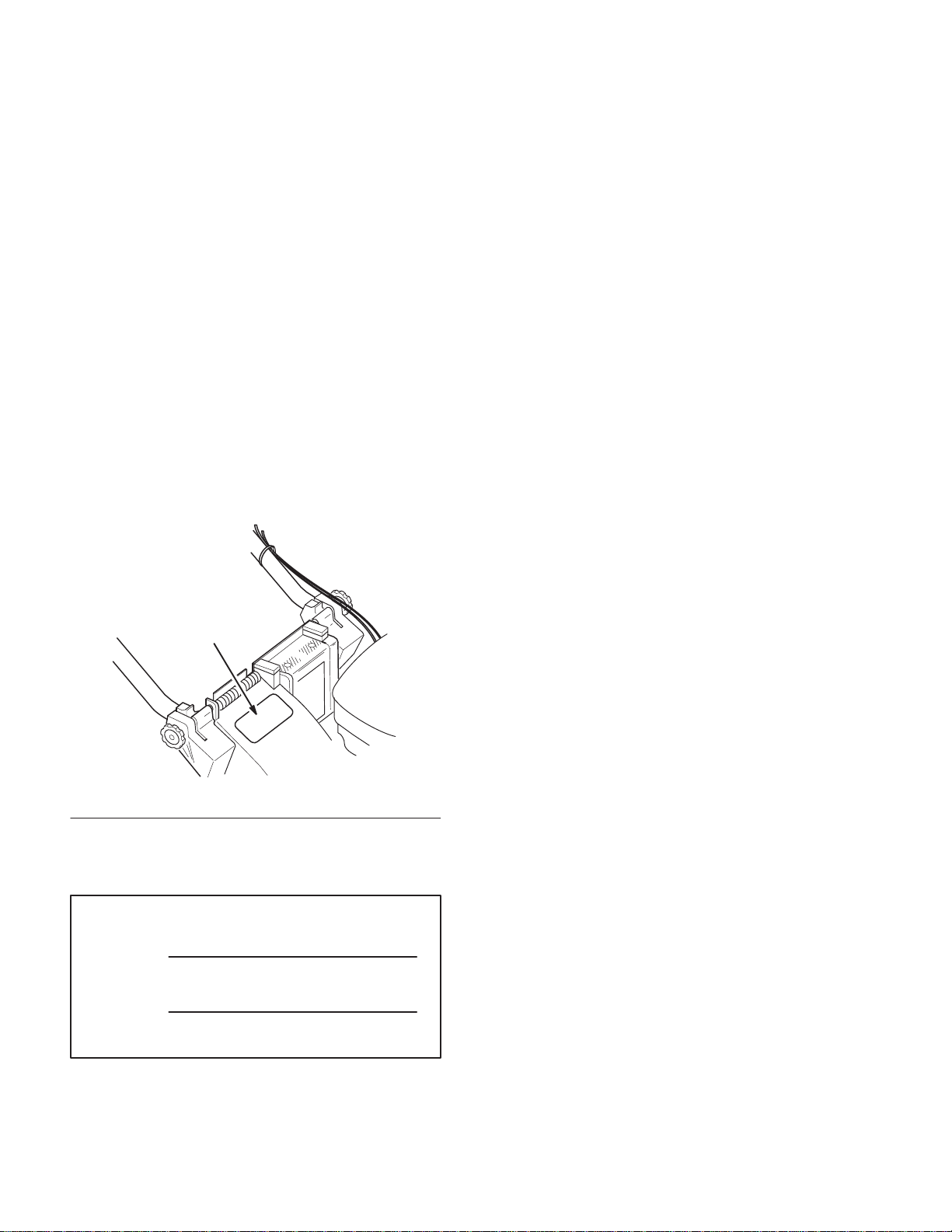
Whenever you contact your Authorized Service
Dealer or the factory, always know the model and
serial numbers of your product. These numbers will
help the Service Dealer or Service Representative
provide exact information about your specific
product. You will find the model and serial number
decal located in a unique place on the product as
shown below.
1
Read this manual carefully to learn how to operate
and maintain your product correctly. Reading this
manual will help you and others avoid personal injury
and damage to the product. Although Toro designs,
produces and markets safe, state-of-the-art products,
you are responsible for using the product properly
and safely. You are also responsible for training
persons who you allow to use the product about safe
operation.
The Toro warning system in this manual identifies
potential hazards and has special safety messages that
help you and others avoid personal injury, even death.
DANGER, WARNING and CAUTION are signal
words used to identify the level of hazard. However,
regardless of the hazard, be extremely careful.
DANGER signals an extreme hazard that will cause
serious injury or death if the recommended
precautions are not followed.
WARNING signals a hazard that may cause serious
injury or death if the recommended precautions are
not followed.
1. Model a n d S erial Number Decal
For your convenience, write the product model and
serial numbers in the space below.
Model No:
Serial No.
1694
CAUTION signals a hazard that may cause minor or
moderate injury if the recommended precautions are
not followed.
Two other words are also used to highlight
information. “Important” calls attention to special
mechanical information and “Note” emphasizes
general information worthy of special attention.
The left and right side of the machine is determined
by standing behind the handle in the normal
operator’s position.
Printed in USA
The Toro Company – 1995
All Rights Reserved
Page 3

Contents
Safety 2. . . . . . . . . . . . . . . . . . . . . . . . . . . . . . . . .
Training 2. . . . . . . . . . . . . . . . . . . . . . . . . . .
Preparation 2. . . . . . . . . . . . . . . . . . . . . . . . .
Operation 2. . . . . . . . . . . . . . . . . . . . . . . . . .
Sound Pressure Level 4. . . . . . . . . . . . . . . . .
Sound Power Level 4. . . . . . . . . . . . . . . . . .
Vibration Level 4. . . . . . . . . . . . . . . . . . . . . .
Symbol Glossary 4. . . . . . . . . . . . . . . . . . . .
Assembly 8. . . . . . . . . . . . . . . . . . . . . . . . . . . . . .
Handle 8. . . . . . . . . . . . . . . . . . . . . . . . . . . .
Starter Rope 8. . . . . . . . . . . . . . . . . . . . . . . .
Grass Bag Ramp 9. . . . . . . . . . . . . . . . . . . . .
Discharge Tunnel Plug 9. . . . . . . . . . . . . . . .
Before Starting 10. . . . . . . . . . . . . . . . . . . . . . . . . .
Fill Crankcase With Oil 10. . . . . . . . . . . . . . .
Fill Fuel Tank With Gasoline 11. . . . . . . . . . .
Operation 12. . . . . . . . . . . . . . . . . . . . . . . . . . . . . .
Controls 12. . . . . . . . . . . . . . . . . . . . . . . . . . .
Starting Engine 12. . . . . . . . . . . . . . . . . . . . . .
Stopping Engine 13. . . . . . . . . . . . . . . . . . . . .
Grass Bag 13. . . . . . . . . . . . . . . . . . . . . . . . . .
Discharge Tunnel Plug 14. . . . . . . . . . . . . . . .
Adjusting Cutting Height 14. . . . . . . . . . . . . .
Recycling Tips 15. . . . . . . . . . . . . . . . . . . . . .
Page
Page
Maintenance 17. . . . . . . . . . . . . . . . . . . . . . . . . . . .
Servicing Air Cleaner 17. . . . . . . . . . . . . . . . .
Draining Gasoline 17. . . . . . . . . . . . . . . . . . .
Changing Crankcase Oil 18. . . . . . . . . . . . . .
Spark Plug 18. . . . . . . . . . . . . . . . . . . . . . . . .
Adjusting Throttle 19. . . . . . . . . . . . . . . . . . .
Adjusting Brake Cable 19. . . . . . . . . . . . . . . .
Adjusting Wheel Traction Drive 20. . . . . . . .
Inspecting/Removing/
Sharpening Blade 21. . . . . . . . . . . . . . . . . . .
Lubrication 22. . . . . . . . . . . . . . . . . . . . . . . . .
Cleaning 23. . . . . . . . . . . . . . . . . . . . . . . . . . .
Storage 25. . . . . . . . . . . . . . . . . . . . . . . . . . . . . . . .
GB–1
Page 4

Safety
Training
1. Read the instructions carefully. Be familiar with
the controls and the proper use of the equipment.
2. Never allow children or people unfamiliar with
these instructions to use the lawnmower. Local
regulations may restrict the age of the operator.
3. Never mow while people, especially children, or
pets are nearby.
4. Keep in mind that the operator or user is
responsible for accidents or hazards occurring to
other people or their property.
Preparation
1. While mowing, always wear substantial
footwear and long trousers. Do not operate the
equipment when barefoot or wearing open
sandals.
2. Thoroughly inspect the area where the
equipment is to be used and remove all objects
which may be thrown by the machine.
• If petrol is spilled, do not attempt to start
the engine but move the machine away
from the area of spillage and avoid creating
any source of ignition until petrol vapors
have dissipated.
• Replace all fuel tanks and container caps
securely.
4. Replace faulty silencers.
5. Before using, always visually inspect to see that
the blades, blade bolts and cutter assembly are
not worn or damaged. Replace worn or damaged
blades and bolts in sets to preserve balance.
6. On multi–bladed machines, take care as rotating
one blade can cause other blades to rotate.
Operation
1. Do not operate the engine in a confined space
where dangerous carbon monoxide fumes can
collect.
2. Mow only in daylight or in good artificial light.
3. WARNING – Petrol is highly flammable.
• Store fuel in containers specifically
designed for this purpose.
• Refuel outdoors only and do not smoke
while refuelling.
• Add fuel before starting the engine. Never
remove the cap of the fuel tank or add
petrol while the engine is running or when
the engine is hot.
GB–2
3. Avoid operating the equipment in wet grass,
where feasible.
4. Always be sure of your footing on slopes.
5. Walk, never run.
6. For wheeled rotary machines, mow across the
face of slopes, never up and down.
7. Exercise extreme caution when changing
direction on slopes.
8. Do not mow excessively steep slopes.
9. Use extreme caution when reversing or pulling
the lawnmower towards you.
Page 5

Safety
10. Stop the blade(s) if the lawnmower has to be
tilted for transportation when crossing surfaces
other than grass, and when transporting the
lawnmower to and from the area to be mowed.
11. Never operate the lawnmower with defective
guards or shields, or without safety devices for
example deflectors and/or grass catchers in
place.
12. Do not change the engine governor settings or
overspeed the engine.
13. Disengage all blade and drive clutches before
starting the engine.
14. Start the engine or switch on the motor carefully
according to instructions and with feet well away
from the blade(s).
15. Do not tilt the lawnmower when starting the
engine or switching on the motor, except if the
lawnmower has to be tilted for starting. In this
case, do not tilt it more than absolutely necessary
and lift only the part which is away from the
operator.
16. Do not start the engine when standing in front of
the discharge chute.
• if lawnmower starts to vibrate abnormally
(check immediately).
20. Stop the engine
• whenever you leave the lawnmower;
• before refuelling.
21. Reduce the throttle setting during engine shut
down and, if the engine is provided with a
shut-off valve, turn the fuel off at the conclusion
of mowing.
Maintenance and storage
1. Keep all nuts, bolts and screws tight to be sure
the equipment is in safe working condition.
2. Never store the equipment with petrol in the tank
inside a building where fumes may reach an
open flame or spark.
3. Allow the engine to cool before storing in any
enclosure.
4. To reduce the fire hazard, keep the engine,
silencer, battery compartment and petrol storage
area free of grass, leaves, or excessive grease.
17. Do not put hands or feet near or under rotating
parts. Keep clear of the discharge opening at all
times.
18. Never pick up or carry a lawnmower while the
engine is running.
19. Stop the engine and disconnect the spark plug
wire.
• before clearing blockages or unclogging
chute;
• before checking, cleaning or working on the
lawnmower;
• after striking a foreign object. Inspect the
lawnmower for damage and make repairs
before restarting and operating the
lawnmower;
5. Check the grass catcher frequently for wear or
deterioration.
6. Replace worn or damaged parts for safety.
7. If the fuel tank has to be drained, this should be
done outdoors.
GB–3
Page 6
Safety
Sound Pressure Level
Model 21012B
This unit has an equivalent continuous A-weighted
sound pressure at the operator ear of: 80.2 dB(A),
based on measurements of identical machines per
ANSI B71.5-1984 procedures.
Model 21013B
This unit has an equivalent continuous A-weighted
sound pressure at the operator ear of: 81.9 dB(A),
based on measurements of identical machines per
ANSI B71.5-1984 procedures.
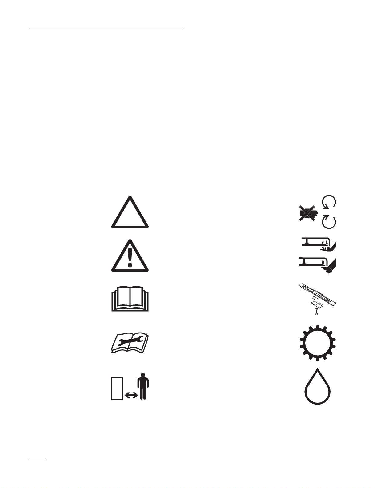
Symbol Glossary
Safety alert triangle —
symbol within triangle
indicates a hazard.
Sound Power Level
This unit has a sound power level of: 96 dB(A)/1 pW,
based on measurements of identical machines per
Directive 84/538/EEC and amendments.
Vibration Level
This unit has a maximum hand-arm vibration level of
5.41 m/s, based on measurement of identical
machines per ISO 5349 procedures.
Do not open or
remove safety shields
while engine is
running.
Safety alert symbol
Read operator’s
manual.
Consult technical
manual for proper
service procedures.
Stay a safe distance
from the machine.
Rotating blade can cut
off toes or fingers.
Stay clear of mower
blade as long as
engine is running.
To avoid blade failure
when mulching, use
blade stiffener when
mower is equipped
with mulching plug.
Transmission
Oil
GB–4
Page 7

Safety
Stay a safe distance
from the mower.
Throw or flying
objects — Whole body
exposure
Thrown or flying
objects — Rotary
side-mounted mower.
Keep deflector shield
in place.
Stop engine before
leaving operator
position.
Hourmeter/elapsed
operating hours
On/Run
Engage
Disengage
Battery charging
condition
Fuel
Fast Neutral
Slow First gear
Decreasing/Increasing Second gear
Grease lubrication
point
Third gear
GB–5
Page 8

Safety
Engine start
Engine stop
Choke Pull rope.
Primer (start aid) Wheel
Push primer three
times.
Cutting element —
basic symbol
Cutting element —
height adjustment
Wheel traction
Properly dispose of
batteries.
Insert key in ignition
switch.
Turn key in ignition
switch.
Move control.
Lower control bar.
Raise control bar.
Raise/lower control
bar.
Raise/lower control
bar.
GB–6
Page 9

Move control forward. Raise control bar.
Safety
Move control
rearward.
Raise control bar.
Lower control bar.
GB–7
Page 10

Assembly
Handle
Assembly
1. Loosen knobs on mounting brackets (Fig. 1).
2
2
6. Use cable ties to secure cables to left handle
(Fig. 2).
Note: Make sure cables do not interfere with
the raising or lowering of discharge
door.
2
1
1694
Figure 2
1. Cable ti e 2. Cables
1
3
1. Knob
2. Handle bracket
Figure 1
3. Housing pocket
1693
2. Position mounting brackets in a vertical position
so that holes face up.
3. Slide handle ends into holes in mounting
brackets until handle ends are completely seated
in brackets (Fig. 1). Make sure cables are
positioned on top of left mounting bracket
(Fig. 2).
4. Rotate handle and mounting brackets rearward
until brackets fit securely into housing pockets
(Fig. 2).
5. Tighten knobs until edges of slots on top of
mounting brackets touch.
Starter Rope
1. Pull starter rope through rope guide on handle
(Fig. 3). By squeezing control bar to handle,
blade brake will release and allow rope to be
pulled up easily to loop.
1
2
1690
Figure 3
1. Recoil starter 2. Rope guide
GB–8
Page 11

Assembly
Grass Bag Ramp
1. Snap three (3) tabs on grass bag ramp onto grass
bag frame (Fig. 4 & 5).
1
23
1. Grass bag ramp
2. Tab
Figure 4
3. Grass bag frame
1713
Discharge Tunnel Plug
1. Make sure engine is off.
2. Open discharge door and insert plug into
discharge tunnel opening (Fig. 6). Since the plug
is slightly wider than the discharge tunnel
opening, you must rotate the plug clockwise
slightly while inserting it.
1
1339
Figure 6
1. Plug
Figure 5
3. Push plug all the way into the discharge tunnel
opening.
4. Lower discharge door over plug.
1714
GB–9
Page 12

Before Starting
Fill Crankcase With Oil
Initially, crankcase must be filled with 0.6 L (20
ounces) of SAE 30 oil. Use any high quality detergent
oil having the American Petroleum Institute (API)
“service classification”—SF, SG or SH.
Before each use, assure oil level is between ADD and
FULL marks (Fig. 7). Add oil if level is low.
4
3
2
1
MARK BECAUSE ENGINE COULD BE
DAMAGED WHEN STARTED. POUR OIL
SLOWLY.
Note: Check oil level each time mower is
used or after every 5 hours of mower
operation. Initially, change oil after the
first 2 hours of operation; thereafter,
change oil after every 25 hours of
operation. More frequent oil changes
are required in dusty or dirty
conditions.
4. Insert dipstick into filler neck and rotate cap
clockwise 1/4 turn to lock it in place.
Fill Fuel Tank With Gasoline
POTENTIAL HAZARD
• In certain conditions gasoline is extremely
flammable and highly explosive.
Figure 7
1. Dipstick
2. Fuel tank cap
1. Position mower on level surface and clean
around oil dipstick.
2. Remove dipstick by rotating cap
counterclockwise 1/4 turn.
3. Wipe dipstick and insert it into filler neck.
Rotate cap 1/4 turn. Then remove dipstick and
check level of oil (Fig. 7). If level is low, add
only enough oil to raise level to FULL mark on
dipstick. DO NOT FILL ABOVE FULL
3. ADD mark
4. FULL mark
1691
WHAT CAN HAPPEN
• A fire or explosion from gasoline can burn
you, others, and cause property damage.
HOW TO AVOID THE HAZARD
• Use a funnel and fill the fuel tank outdoors,
in an open area, when the engine is cold.
Wipe up any gasoline that spills.
• Do not fill the fuel tank completely full.
Add gasoline to the fuel tank until the level
is 6 mm to 13 mm (1/4” to 1/2”) below the
bottom of the filler neck. This empty space
in the tank allows gasoline to expand.
• Never smoke when handling gasoline, and
stay away from an open flame or where
gasoline fumes may be ignited by a spark.
• Store gasoline in an approved container
and keep it out of the reach of children.
• Never buy more than a 30-day supply of
gasoline.
GB–10
Page 13

1. Clean around fuel tank cap and remove cap from
tank (Fig. 7). Do not fill tank full. Using
unleaded gasoline, fill fuel tank to within 6 to 13
mm (1/4” to 1/2”) from top of tank, not into
filler neck.
2. Install fuel tank cap and wipe up any spilled
gasoline.
Toro also recommends that Toro
Stabilizer/Conditioner be used regularly in all Toro
gasoline powered products during operation and
storage seasons. Toro Stabilizer/Conditioner cleans
the engine during operation and prevents gum-like
varnish deposits from forming in the engine during
periods of storage.
IMPORTANT: Do not mix oil with the
gasoline. Never use methanol
, gasoline
containing methanol, gasohol containing
more than 10% ethanol, premium gasoline, or
white gas because engine fuel system damage
could result.
Before Starting
Do not use fuel additives other than those
manufactured for fuel stabilization during
storage such as Toro’s Stabilizer/Conditioner
or a similar product. Toro’s
Stabilizer/Conditioner is a petroleum
distillate based conditioner/stabilizer. Toro
does not recommend stabilizers with an
alcohol base such as ethanol, methanol or
isopropyl. Additives should not be used to try
to enhance the power or performance of
machine.
GB–11
Page 14

Operation
Controls
Self-propelled control bar (self-propelled model),
throttle, blade control bar and recoil starter are on the
handle (Fig. 8 and 9).
1
3
Hand push model
2
2365
4
1. Throttle lever
2. Blade control bar
2
3
1
2339
Self-propelled model
Figure 9
3. Self-propelled control bar
4. Recoil starter
1. Throttle lever
2. Blade control bar
Figure 8
3. Recoil starter
Starting Engine
1. Push spark plug wire onto spark plug (Fig. 10).
2. Push primer three (3) times (Fig. 10). Wait
about two (2) seconds between each push.
2
1
Figure 10
1. Primer 2. Spark plug wire
1344
GB–12
Page 15

Operation
Note: Do not use primer to restart a warm
engine after a short shutdown.
However, cool weather may require
priming to be repeated.
3. Move throttle forward to
(FAST) position.
Hand Push model
• Hold blade control bar against handle.
• Pull recoil starter out until slack in rope is taken
up. Then pull vigorously to start the engine.
Self-propelled model
• Hold blade control bar against handle.
• Pull recoil starter out until slack in rope is taken
up. Then pull vigorously to start the engine.
• Slowly squeeze the self-propelled control bar
against the handle to engage the traction
mechanism. The mower is equipped with a
single ground speed. When the control bar is
tight against the handle, the mower will
self–propel at maximum ground speed.
4. When engine starts, regulate throttle as desired
between
(FAST) and (SLOW).
To Restart Engine
1. Move throttle lever to (FAST) position and
repeat steps 3 and 4 in STARTING ENGINE
procedure.
2. If engine does not start after two attempts, repeat
steps 2–4 in STARTING ENGINE procedure.
Grass Bag
Installing
1. Stop engine and wait for all parts to stop.
2. Raise discharge door, slide bag ramp attached to
bag into discharge opening, and hook bag frame
onto mounting bracket (Fig. 11). Allow
discharge door to rest on top of bag (Fig. 12).
3
1
2
4
Stopping Engine
1. Release blade control bar. Engine and blade will
stop. See your dealer immediately if they do not.
To stop self-propelling, release the self-propel
control bar. Stay behind the handle until all
moving parts stop.
2. Pull wire off spark plug if mower will be
unattended or not used.
1. Discharge door
2. Bag ramp
1715
Figure 11
3. Bag frame hook
4. Mounting bracket
GB–13
Page 16

Operation
Figure 12
Removing
1. Stop engine and wait for all moving parts to
stop. For protection, always keep hands and feet
away from mower housing while engine is
running. Raise discharge door. While holding
discharge door up, grasp handle on grass bag and
lift bag off mower. Allow discharge door to
close.
Note: When removing the grass bag, the bag
ramp scoops out any clippings that
may be plugging the discharge
opening. If the discharge opening
remains plugged, clear all clippings
from the mower with a stick.
Emptying
1. Grasp bag frame handle and rear of grass bag.
Gradually tip bag forward to empty clippings.
Discharge Tunnel Plug
1. Make sure engine is off.
795
1
1339
Figure 13
1. Plug
3. Push plug all the way into the discharge tunnel
opening.
4. Lower discharge door over plug.
Adjusting Cutting Height
The six (6) letters on the belt cover represent the
height-of-cut settings. All wheels automatically adjust
to the same height-of-cut setting.
1. Stop the engine and pull wire off spark plug
(Fig. 10).
2. Use one or two fingers to squeeze the
height-of-cut adjustment lever (Fig. 14).
To raise the wheel height, squeeze the lever to
unlock the height-of-cut and pull up on the
mower. Release lever when desired height is
found. To lower the height, squeeze the
height-of-cut adjustment lever and push down on
the mower while rolling the mower forward.
Use the pointer on the link rod to locate the
correct setting.
2. Open discharge door and insert plug into
discharge tunnel opening (Fig. 13). Since the
plug is slightly wider than the discharge tunnel
opening, you must rotate the plug clockwise
slightly while inserting it.
GB–14
3. Make sure the height adjustment lever is locked
into a height setting before beginning operation.
The height should not change when the
height-of-cut is locked.
Page 17

1
2
Figure 14
1. Height-of-cut adjustment
lever
2. Height settings
Recycling Tips
3
3. Pointer
4. Link rod
Operation
POTENTIAL HAZARD
• Wet grass or leaves can cause you to slip
and contact blade.
WHAT CAN HAPPEN
• Blade contact can seriously injure you.
HOW TO AVOID THE HAZARD
• Mow only in dry conditions.
• Set engine speed to fastest position. Maximum
horsepower provides best cutting results.
• Clean clippings or leaves from underside of
4
1711
mower deck after each mowing.
• Keep engine in good running condition. Cutting
and recutting requires more horsepower.
• Clean air filter more frequently. Cutting and
recutting stirs up more clippings and dust which
clogs the air filter and reduces engine
performance.
General Tips
Follow these instructions whether cutting grass or
leaves for the best cutting results and lawn
appearance:
• Maintain a sharp blade
season. Periodically file down nicks on blade.
Only mow dry grass or leaves. Wet grass and leaves
tend to clump on yard and may cause mower to plug
or engine to stall. They also may be slippery to walk
on and could cause you to slip and fall.
throughout the cutting
Cutting Grass
• Grass grows at different rates at different times
of the year. In the heat of the summer, it is
generally best to cut grass at the C, D or E
height-of-cut settings. Only about 1/3 of the
grass blade should be cut off. Cutting below the
C setting is not recommended unless grass is
sparse or it is late fall when grass growth begins
to slow down.
• When cutting grass over six inches tall, you may
want to first mow using the highest height-of-cut
setting and a slower walking speed; then mow
again at a lower setting for best lawn appearance.
If grass is too long and leaves clumps on top of
lawn, mower may plug and cause engine to stall.
• Alternate mowing direction. This helps disperse
clippings over lawn for even fertilization.
If the finished cut lawn appearance is unsatisfactory,
try one or more of the following:
GB–15
Page 18

Operation
• Sharpen the blade.
• Walk at a slower pace while mowing.
• Raise the height-of-cut setting on your mower.
• Cut grass more frequently.
• Overlap cutting swaths instead of cutting a full
swath with each pass.
• Mow across the marginal areas a second time.
Cutting Leaves
• When cutting is complete, always be sure that
50% of the lawn shows through the cut leaf
cover. This may require one or more passes over
the leaves.
• Walk at a slower mowing speed if leaves are not
being cut up finely enough to be hidden down in
the grass.
• If you cut up a lot of oak leaves, you might want
to add lime to your grass in the spring. Lime
reduces the acidity of oak leaves.
GB–16
Page 19

Maintenance
POTENTIAL HAZARD
• If you leave the wire on the spark plug, someone could start the engine.
WHAT CAN HAPPEN
• Accidental starting of engine could seriously injure you or other bystanders.
HOW TO AVOID THE HAZARD
• Pull wire off spark plug before you do any maintenance. Also push wire aside so it
does not accidentally contact spark plug.
Servicing Air Cleaner
Normally, replace air cleaner after every 25 operating
hours. More frequent replacing is required when
mower is operated in dusty or dirty conditions. See
your Authorized Toro Service Dealer for replacement
parts.
1. Stop engine and pull wire off spark plug
(Fig. 15).
1
Figure 15
1. Spark plug wire
1002
IMPORTANT: Do not operate engine without
air cleaner filter otherwise extreme engine
wear and damage will likely result.
3
1
2
Figure 16
1. Cover
2. Screw
3. Paper filter
Draining Gasoline
1. Stop engine and wait for engine to cool. Pull
wire off spark plug (Fig. 15).
1003
2. Remove screw securing air cleaner cover to
engine (Fig. 16). Tilt cover down and clean
cover thoroughly.
3. Remove paper air cleaner filter (Fig. 16) and
discard.
4. Insert a new paper air cleaner filter.
5. Reinstall air cleaner cover and secure with screw.
IMPORTANT: Drain gasoline from a cold
engine only.
2. Remove cap from fuel tank and use a pump-type
syphon to drain fuel into a clean gas can.
Note: This is the only procedure
recommended for draining fuel.
GB–17
Page 20

Maintenance
Changing Crankcase Oil
Change oil after the first 2 operating hours and after
every 25 hours thereafter. Since warm oil drains
better and carries more contaminants than cold, run
engine for several minutes or so before draining oil.
1. Stop engine and pull wire off spark plug
(Fig. 15).
2. Drain gasoline from fuel tank: refer to Draining
Gasoline.
3. Tip mower on its left side (Fig. 17).
4. Place a drain pan under mower.
5. Remove drain plug from underside of mower
(Fig. 17).
1
Spark Plug
Use a Champion RJ19LM spark plug or equivalent.
Correct air gap is 0.76 mm (0.030”). Remove plug
after every 25 operating hours and check its
condition.
1. Stop engine and pull wire off spark plug
(Fig. 15).
2. Clean around spark plug and remove plug from
cylinder head.
IMPORTANT: Replace a cracked, fouled, or
dirty spark plug. Do not sand blast, scrape, or
clean electrodes because engine damage could
result from grit entering cylinder.
3. Set air gap at 0.76 mm (0.030”) (Fig. 18). Install
correctly gapped spark plug and gasket seal.
Tighten plug firmly to 20 Nm (15 ft-lb).
.76 mm
(.030”)
1973
Figure 17
1. Oil drain plug
6. Lower mower allowing oil to drain into pan.
7. After draining, clean drain plug and reinstall it.
8. Set mower upright.
9. Wipe up any spilled oil.
10. Fill engine with fresh oil: refer to Fill Crankcase
With Oil.
GB–18
986
Figure 18
4. Reconnect spark plug wire when maintenance is
completed.
Page 21

Maintenance
Adjusting Throttle
Throttle control adjustment may be required if engine
does not start or stop. Whenever a new throttle
control cable is installed, throttle must be adjusted.
1. Stop engine and pull wire off spark plug
(Fig. 15).
2. Remove (2) screws from engine cover and lift
off cover (Fig. 19).
2
1
1709
Figure 19
1. Cover 2. Screw (2)
4. Move throttle control to (FAST) position.
5. Move throttle cable until throttle lever contacts
stop (Fig. 20).
6. Tighten cable clamp screw to lock adjustment in
place.
7. Reinstall engine cover with (2) screws. Torque
screws to 8-10 in.-lbs. (.9-1.1 Nm)
Adjusting Brake Cable
Whenever a new blade brake cable assembly is
installed, an adjustment is required.
1. Stop the engine. Pull the wire off the spark plug.
2. CHECK ADJUSTMENT–Move the blade
control bar toward the handle until the slack in
the wire is removed. The gap between the blade
control bar and the handle must be
1.5mm-4.6mm (/”–/”) (Fig. 21 and
Fig. 22).
3. Loosen cable clamp screw until throttle cable
slides (Fig. 20).
3
4
2
Figure 20
1. Cable clamp screw
2. Throttle cable
3. Throttle lever
4. Stop
1
1,5-4,6 mm
2348
(1/16”-3/16”)
Self-propelled model shown
Figure 21
2340
GB–19
Page 22

Maintenance
2
3
Self-propelled model shown
1. Cable conduit
2. Cable bracket
1
Figure 22
3. Nut
2341
3. ADJUST CABLE CONDUIT–Loosen the nut on
the cable bracket. Insert 1.5mm-4.6mm
(/”–/”) object between the brake control
bar and handle. Pull down on the cable conduit
until all slack is removed from the wire. Then
tighten the nut.
Adjusting Wheel Traction Drive
(self-propelled model only)
If mower does not self-propel or has a tendency to
creep forward when drive is not engaged, an
adjustment to the wheel traction control cable is
necessary.
1. Stop the engine.
2. Turn knob clockwise if mower has tendency to
creep when drive is not engaged. Turn knob
counterclockwise if mower does not propel when
drive is engaged.
1
2341
Figure 23
1. Adjustment knob
Note: Determine left and right sides of
mower by standing in the operator’s
position.
Adjustment is correct when:
• mower does not creep forward when traction is
disengaged
• self-propelled control bar is at a comfortable
operating distance from the handle for operator’s
hand when disengaging and engaging the
self-propelled drive
Note: Do not overadjust cable. Cable should
be just tight enough to make wheels
turn when self-propelled control bar is
at a distance from the handle that is
comfortable for operator’s hand.
Overadjusting may require excessive
operator effort to engage or disengage
self-propelled drive.
If you need help, see your Authorized Toro Service
Dealer.
GB–20
Page 23

Maintenance
Inspecting/Removing/
Sharpening Blade
A straight, sharp blade provides maximum cutting
performance. Regularly inspect and sharpen blade.
POTENTIAL HAZARD
• Blade is sharp.
WHAT CAN HAPPEN
• Contact with sharp blade can cause serious
personal injury.
HOW TO AVOID THE HAZARD
• Wear gloves or wrap sharp edges of the
blade with a rag.
1. Stop engine and pull wire off spark plug
(Fig. 15).
2. Drain gasoline from fuel tank. See Drain
Gasoline section.
3
1. Blade
2. Blade stiffener
1
Figure 24
3. Blade bolt and lockwasher
2
4. INSPECTING BLADE—Carefully examine
blade for sharpness and wear, especially where
flat and curved parts meet (Fig. 25A). Since sand
and abrasive material can wear away the metal
that connects the flat and curved parts of the
blade, check blade before using the mower. If a
slot or wear is noticed, (Fig. 25B & C), replace
blade. Refer to step 5.
1973
POTENTIAL HAZARD
• Gasoline is extremely flammable, highly
explosive and under certain conditions can
cause personal injury or property damage.
WHAT CAN HAPPEN
• Tipping mower may cause fuel leakage
from carburetor or fuel tank.
HOW TO AVOID THE HAZARD
• Avoid fuel spills by running engine dry or
remove gas with hand pump, never siphon.
3. Tip mower on its left side (Fig. 24). Avoid
rotating the blade because starting problems may
result.
A
B
C
1. Sail
2. Flat part of blade
Figure 25
3. Wear
4. Slot formed
1
2
3
4
1
1
270
GB–21
Page 24

Maintenance
Note: For best performance, install new blade
before cutting season begins. During
the year, file down small nicks to
maintain the cutting edge.
POTENTIAL HAZARD
• A worn or damaged blade could break and
a piece of blade could be thrown into
operator’s or bystander’s area.
WHAT CAN HAPPEN
• A thrown piece of blade could cause serious
personal injury or death to operator or
bystanders.
HOW TO AVOID THE HAZARD
• Inspect blade periodically for wear or
damage.
• Replace a worn or damaged blade.
1
153
Figure 26
1. Sharpen a t this angle only
7. Install sharp, balanced TORO blade, blade
stiffener, lockwasher and blade bolt. Sail part of
blade must point toward top of mower housing
to ensure correct installation. Tighten the blade
bolt to 68 Nm (50 ft–lb).
POTENTIAL HAZARD
• When sharpening blade, pieces of blade
could be accidentally thrown.
5. REMOVING BLADE—Grasp end of blade
using a rag or thickly padded glove. Remove
blade bolt, lockwasher, blade and blade stiffener
(Fig. 24).
6. SHARPENING BLADE—Using a file, sharpen
top side of blade and maintain original cutting
angle (Fig. 26). The blade will remain balanced
if same amount of material is removed from both
cutting edges.
IMPORTANT: Check balance of blade by
putting it on a blade balancer. An inexpensive
balancer can be purchased at a hardware
store. A balanced blade stays in a horizontal
position and an unbalanced blade settles to
the heavy side. If blade is not balanced, file
more metal off cutting edge on heavy end of
blade.
WHAT CAN HAPPEN
• Thrown objects can cause serious eye
injury.
HOW TO AVOID THE HAZARD
• Wear proper eye protection when
sharpening blade.
POTENTIAL HAZARD
• Operating mower without stiffener in place
could cause blade to flex, bend or break.
WHAT CAN HAPPEN
• A broken blade could cause serious injury
or death to operator or bystanders.
HOW TO AVOID THE HAZARD
• Do not operate mower without stiffener.
Lubrication
GB–22
After every 25 operating hours or when season ends,
front and rear wheels must be lubricated.
Page 25

Maintenance
1. Apply one or two drops of light oil on inside and
outside of all wheel bolts. Spin wheels to
distribute oil into bushings. Wipe up excess oil.
2. SELF-PROPELLED MODEL–Drain gasoline;
refer to Draining Gasoline, page 17.
3. Set mower to highest height-of-cut setting (E).
4. Tip mower on its left side. Wipe grease fittings
with clean rag (Fig. 27). Install grease gun onto
fitting and gently apply one or two pumps of #2
Multi-Purpose Lithium Base Grease.
Underside of Mower Housing
Keep underside of mower housing clean. Be
especially careful to keep kickers free of debris
(Fig. 29).
Washing Method
1. Position mower on a flat surface near a garden
hose.
2. Start the engine.
3. Hold the running garden hose at handle level and
direct water to flow on ground just in front of
right rear tire (Fig. 28). The rotating blade will
draw water under the housing and wash out
clippings. Let the water run for a few minutes or
until you no longer see clippings being washed
out from under housing.
1
1
782
Figure 27
1. Grease fitting (self-propelled model
Cleaning
Plug and Discharge Tunnel
To ensure best performance, the discharge tunnel plug
must be cleaned after each use. When grass is thick
and lush, clippings may collect on and around the
plug; this may make plug removal difficult. After
each use, remove plug from discharge tunnel and
clean off all debris.
1
Figure 28
1. Right rear wheel
1093
4. Stop the engine.
5. Turn off the garden hose.
6. Restart mower and let it run for a few minutes to
dry out moisture on the mower and its
components.
Scraping Method
If washing does not remove all debris from under
deck, tip mower and scrape it clean.
1. Pull wire off spark plug.
GB–23
Page 26

Maintenance
2. Drain gasoline; refer to Draining Gasoline,
page 17.
POTENTIAL HAZARD
• Gasoline is extremely flammable, highly
explosive and under certain conditions can
cause personal injury or property damage.
WHAT CAN HAPPEN
• Tipping mower may cause fuel leakage
from carburetor or fuel tank.
HOW TO AVOID THE HAZARD
• Avoid fuel spills by running engine dry or
remove gas with hand pump, never siphon.
3. If grass bag is installed on mower, close door in
mower housing and remove grass bag.
4. Tip mower on its left side (Fig. 29). Avoid
rotating blade because starting problems may
result.
1
Figure 29
1. Kicker plates
5. Remove dirt and grass clippings with a
hardwood scraper. Avoid burrs and sharp edges.
1973
6. Turn mower upright.
7. Refill gas tank.
8. Reconnect spark plug wire.
GB–24
Page 27

Storage
1. For long term storage, it is recommended that
gasoline be drained from fuel tank or use a fuel
additive before storing. To drain gasoline, refer
to Draining Gasoline. After fuel is drained, start
engine and let it idle until all fuel is consumed
and engine stops. If gasoline is not drained,
gum–like varnish deposits will form and cause
poor engine operation or even starting problems.
Fuel can be left in gas tank only if a fuel
additive, such as Toro’s Stabilizer/Conditioner, is
added to gasoline and run through engine before
storing. Toro’s Stabilizer/Conditioner is a
petroleum distillate based conditioner/stabilizer.
Toro does not recommend stabilizers with an
alcohol base, such as ethanol, methanol or
isopropyl. Use fuel additive in recommended
quantities as specified on container.
Under normal conditions, fuel additives remain
effective in fuel for 6-8 months.
2. Drain oil: refer to Changing Crankcase Oil. After
oil is drained, do not fill crankcase with oil until
the following steps (3–10) are completed.
9. Lubricate the wheels; refer to Lubrication
section.
10. Touch up all rusted or chipped paint surfaces.
Toro Re-Kote paint is available from an
Authorized TORO Service Dealer.
11. Fill crankcase with oil; refer to Fill Crankcase
With Oil.
12. Store mower in a clean, dry place. Cover mower
to keep it clean and protected.
3. Remove spark plug and pour 30 ml
(2 tablespoons) of SAE 30 oil into hole in
cylinder. Pull starter rope slowly to coat inside of
cylinder. Install spark plug and tighten to 20 Nm
(15 ft–lb). DO NOT INSTALL WIRE ON
SPARK PLUG.
4. Clean mower housing; refer to Cleaning Mower
Housing.
5. Check condition of blade; refer to
Inspecting/Removing/Sharpening Blade.
6. Tighten all nuts, bolts, and screws.
7. Clean dirt, chaff, grass clippings, and grime from
external parts of the engine, shrouding, and top
of mower housing.
8. Clean air cleaner; refer to Servicing Air Cleaner.
GB–25
Page 28

 Loading...