


Form No. 3325–659
48cm Recycler
Walk Power Lawn Mower
Model No. 20828–210001001 and Up
Parts Catalog
Ordering Replacement Parts
To order replacement parts, please supply: the part
number, the quantity, and the description of each
part desired.
Understanding Reference Numbers
Each identified part in an illustration has a reference
number. The reference number for a part also appears in
the parts list, along with other information about the part.
This catalog uses two special reference number formats,
one to indicate parts in a service assembly and another
to indicate the quantity of a given part in an illustration.
Service Assembly Reference Numbers
Parts in service assemblies have reference numbers in
the form a:b.
the entire service assembly and the b represents a
sequential number unique to each part within the service
assembly.
The a represents the reference number of
The TORO Company — 2001
All Rights Reserved
For example, a wheel assembly might be identified by
reference number 6, the tire by 6:1, the valve by 6:2,
and the wheel by 6:3. When you order the assembly
identified by reference number 6, you receive all parts
identified by reference numbers 6:1, 6:2, and 6:3.
However, you may also order any part individually.
Reference numbers of this type appear in illustrations
and in part lists.
Reference Numbers Indicating Quantity
In an illustration, if a reference number indicates more
than one part, the reference number has the form nX y.
The n represents the quantity of the part, the X is the
multiplication symbol, and the y represents the reference
number.
For example, in an illustration, the reference number
2X 37 means that two of the parts identified by reference
number 37 are indicated.

3325–659
Contents
Description Page Description Page
Deck, Kicker and Recycler Plug Assembly 3. . . .
Engine and Blade Assembly 4. . . . . . . . . . . . . . . .
Height–Of–Cut and Wheel Assembly 5. . . . . . . . .
Self Propel Handle and Control Assembly 6. . . .
Rear Bagger Components 7. . . . . . . . . . . . . . . . . .
Gearcase and Drive Assembly 8. . . . . . . . . . . . . .
Gearcase Assembly No. 104–7593 9. . . . . . . . . .
Cylinder Assembly 10. . . . . . . . . . . . . . . . . . . . . . . . .
Cylinder Head Assembly 11. . . . . . . . . . . . . . . . . . .
Crankcase and Crankshaft Assembly 12. . . . . . . .
Carburetor Overhaul Kit Assembly 13. . . . . . . . . . .
Governor Assembly 14. . . . . . . . . . . . . . . . . . . . . . . .
Air Cleaner and Exhaust Assembly 15. . . . . . . . . .
Fuel Tank Assembly 16. . . . . . . . . . . . . . . . . . . . . . .
Flywheel Assembly 17. . . . . . . . . . . . . . . . . . . . . . . .
Starter Assembly 18. . . . . . . . . . . . . . . . . . . . . . . . . .
Gasket Sets 19. . . . . . . . . . . . . . . . . . . . . . . . . . . . . .
Part Description Abbreviations
Part descriptions in this catalog may include the following abbreviations.
Abbreviation Meaning Abbreviation Meaning
AR as required. . . . . . . . . . . . . . . . .
ASM assembly. . . . . . . . . . . . . . . .
CARR carriage. . . . . . . . . . . . . .
DEG degrees. . . . . . . . . . . . . . . .
FH flat head. . . . . . . . . . . . . . . . .
GA gauge. . . . . . . . . . . . . . . . .
HF hex flange. . . . . . . . . . . . . . . . .
HH hex head. . . . . . . . . . . . . . . . .
HHF hex head flange. . . . . . . . . . . . . . . .
HLH hex lag head. . . . . . . . . . . . . . . .
HJ hex jam. . . . . . . . . . . . . . . . . .
HOC height-of-cut. . . . . . . . . . . . . . . .
HS hex socket. . . . . . . . . . . . . . . . .
HSBH hex socket button head. . . . . . . . . . . . . .
HSFH hex socket flat head. . . . . . . . . . . . . . .
HSH hex socket head. . . . . . . . . . . . . . . .
HWH hex washer head. . . . . . . . . . . . . . .
HWHTF hex washer head. . . . . . . . . . . . .
thread forming
HYD hydraulic. . . . . . . . . . . . . . . .
INC incorporated. . . . . . . . . . . . . . . . .
LH left hand. . . . . . . . . . . . . . . . .
NI nylon insert. . . . . . . . . . . . . . . . . .
PPH Phillips pan head. . . . . . . . . . . . . . . .
PTH Phillips truss head. . . . . . . . . . . . . . . .
PTO power take off. . . . . . . . . . . . . . . .
RH right hand. . . . . . . . . . . . . . . . .
SFH slotted fillister head. . . . . . . . . . . . . . . .
SHH slotted hex head. . . . . . . . . . . . . . . .
SQH square head. . . . . . . . . . . . . . . .
SHWH slotted hex washer head. . . . . . . . . . . . . .
SPH slotted pan head. . . . . . . . . . . . . . . .
SRH slotted round head. . . . . . . . . . . . . . . .
STD standard. . . . . . . . . . . . . . . .
TAP self tapping. . . . . . . . . . . . . . . .
TTH Torx truss head. . . . . . . . . . . . . . . .
WH wing head. . . . . . . . . . . . . . . . .
2
17
16
18
19
21
3325–659
6
7
28
1:2
26
27
1
4
5
24
20
7
3
15
7
14
13
12
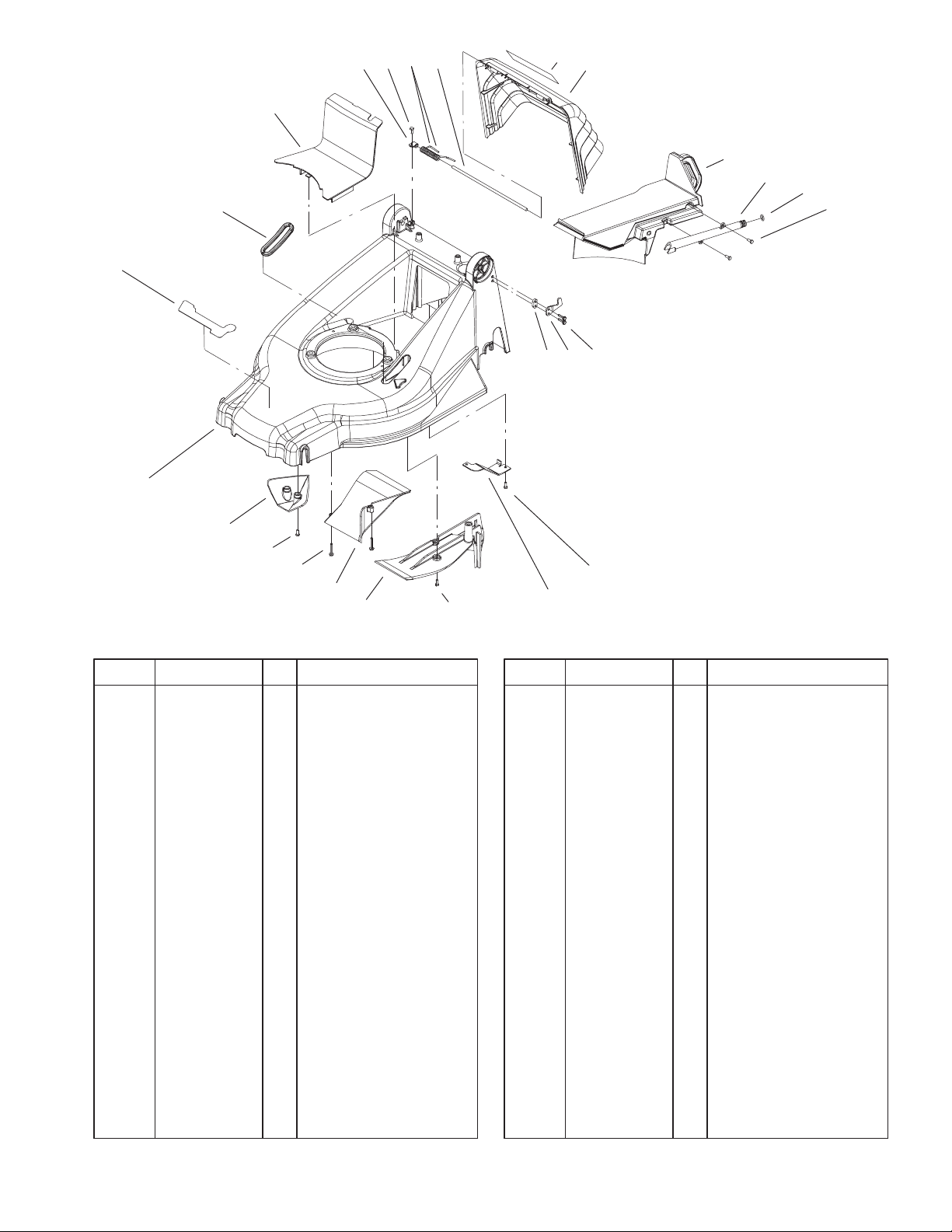
Deck, Kicker and Recycler Plug Assembly
DescriptionPart No. Qty.Ref. No. DescriptionPart No. Qty.Ref. No.
1 100–9115 1 Door ASM
1:2 93–4105 1 Decal – Danger
3 100–1509 1 Rod–Pivot, Door
4 100–1505 1 Recycler–Plug, Kicker
5 100–1522 1 Fitting–Washout
6 46–6290 1 O–Ring
7 32144–1 11 Screw–Taptite
12 99–6486 1 Kicker–Cover, Rear
13 100–1506 1 Ramp–Discharge
14 100–4352 2 Screw–HWH
15 99–6485 1 Kicker–Front
16 104–7573–01 1 Deck
17 100–4354 1 Decal–Recycler
18 100–3932 1 Boot–HOC
19 99–6479 1 Belt Cover
20 104–7594 1 Spring–Torsion, Door
21 98–2256 2 Clamp
22 100–9123–03 1 Bracket – Deck
24 100–4351 4 Screw–HWH
26 104–7557 1 Hook–Left
*27 104–7558 1 Hook–Right
28 104–7556 2 Spacer
7
7
22
Sheet No.:2
* Not illustrated
3

3325–659
18
17
16
20
19
3
6
7
15
9
10
8
14
13
12
Engine and Blade Assembly
DescriptionPart No. Qty.Ref. No. DescriptionPart No. Qty.Ref. No.
3 1 Engine– GTS 200
6 100–1523–03 1 Guide–Belt, Engine
7 93–0232 1 V–Belt
8 32144–4 2 Screw–HWH
9 80–0510–03 1 Blade Stiffener
10 3253–22 1 Washer–Lock
11 100–4368 1 Bolt–Blade
12 71–9260–03 1 Blade
13 104–7554 1 Retainer–Blade
14 100–1102 1 Pulley ASM
15 104–0214 1 Screw–Set
16 32144–102 3 Screw–HWH
17 92–2289 1 Plate–Logo
18 100–5951 1 Decal–Engine
19 2210–316 1 Stop–Rope
20 93–7198 1 Gas Cap ASM
11
Sheet No.:3
4

25
23
24
22
3325–659
1
2
27
3
4
5
7
8
12
9
8
29
21
28
20
11
6
8
10
13
14
1
15
16
17
18
16:2
19
Sheet No.:4
Height–Of–Cut and Wheel Assembly
DescriptionPart No. Qty.Ref. No. DescriptionPart No. Qty.Ref. No.
1 100–4352 4 Screw–HWH
2 99–6487 1 Handle–Deck
3 99–6480 1 Button–HOC
4 88–7540 1 Washer–Backup
5 99–6481 1 Spring–Compression,
HOC
6 99–6483 1 Bushing–HOC
7 100–1525 1 Bracket–Cable,
Traction
8 32144–1 6 Screw–Taptite
9 92–9698 1 Screw–Shoulder
10 99–6458 1 Pipe – HOC
11 3296–73 1 Nut–Lock, NI
12 100–4384 1 Spring–Extension,
HOC
13 99–6459 1 Bolt–Shoulder
14 99–6460 1 Plate–Support, HOC
15 99–6478 1 Rear Axle ASM
16 99–6471 2 Wheel ASM
16:2 27–6250 2 Bushing
17 100–4370 2 Nut–Lock, Flanged
18 100–4366 2 Cover–Smart Wheel
19 100–9114 2 Decal–Smart Wheel
20 95–6543 2 Cover – Wheel
21 99–6470 2 Wheel ASM
22 100–1500 4 Mount–Axle, Front
23 104–7562 1 Front Axle ASM
24 100–9116 1 Rod ASM
24:2 100–4355 1 Decal–HOC
25 100–3939 2 Palnut
27 100–4383–03 1 Cover–Handle
28 614650 2 Bolt–Shoulder
29 40–1940 2 Washer
5

3325–659
30
29
20
21
19 18
22
13
28
27
26
2
3
8
5
23
24
8
25
9
10
11
12
14
15
31
17
4
5
7
1
Sheet No.:5
Self Propel Handle and Control Assembly
DescriptionPart No. Qty.Ref. No. DescriptionPart No. Qty.Ref. No.
1 99–1593–03 1 Bail–Brake
2 99–1595 1 Retainer–Cable, Brake
3 46–8091 1 Screw–HWH
4 99–6008 1 Retainer–Control Rod,
Traction
5 94–4496 10 Screw–PPH
7 99–1589 1 Lever–Traction
8 99–1590 2 Guide–Handle, Control
9 95–4453 1 Screw–Handle
10 99–5239 1 Anchor–Cable
11 100–3936 1 Cable–Traction
12 98–7134 2 Knob–Handle
13 92–2260 2 Screw–Handle
14 3290–378 2 Tie–Cable
15 100–1502–05 1 Handle–Lower
17 100–4396 2 Knob–Adjusting,
Handle
18 104–7553–03 2 Disk–Adjusting,
Handle
19 100–1517 2 Disk–Holding, Handle
20 60–6690 2 Capscrew
21 99–1596–05 1 Handle–Upper
22 86–9671 1 Guide–Rope
23 3296–73 2 Nut–Lock, NI
24 3256–1 1 Washer–Flat
25 100–3937 1 Cable–Brake
26 100–5970 1 Cover–Handle
27 99–1592 1 Spring–Torsion, RH
28 99–1588 1 Bar–Control, Traction
29 100–5950 1 Decal–Automatic
30 99–1582 1 Handle–Control
31 100–4351 4 Screw–HWH
6

3325–659
1
2
Rear Bagger Components
DescriptionPart No. Qty.Ref. No. DescriptionPart No. Qty.Ref. No.
1 104–7578 1 Grass Bag ASM
2 104–7560–03 1 Bag Frame ASM
Sheet No.:8
7

3325–659
17
16
15
13
12
12:1
12:2
21
18
20
19
1
2
3
4
5
6,7
8
2
9
3
10
21
Sheet No.:9
Gearcase and Drive Assembly
DescriptionPart No. Qty.Ref. No. DescriptionPart No. Qty.Ref. No.
1 65–4730 2 Washer–Arm, Pivot
2 65–4740 4 Washer–Thrust,
Keyed
3 65–2720 4 Ring–Klip
4 65–4710 2 Ring–Friction
5 65–4760 2 Washer–Clutch
6 66–6040 1 Key–Rocking, RH
7 66–6050 1 Key–Rocking, LH
8 65–4750 2 Gear–Pinion
9 65–4720 2 Spring–Compression
10 100–1513 2 Cover–Gear
12 100–9118 2 Bushing ASM
12:1 99–6463 1 Bushing–Drive Shaft
12:2 302–56 1 Fitting–Zerk
13 104–7593 1 Gear Case ASM
15 614673 1 Bushing–Plate,
Actuator
16 100–1524–03 1 Guide–Transmission
17 49–2040 1 Screw–Tapping
18 92–1616 1 Screw–HWHTF
19 100–1511 2 Retainer–Ring
20 100–1515 2 Washer–Wave
21 32144–1 4 Screw–Taptite
8

7
5
13
15
1
6
4
11
14
17
8
3325–659
19
10
12
16
2
3
Gearcase Assembly No. 104–7593
DescriptionPart No. Qty.Ref. No. DescriptionPart No. Qty.Ref. No.
1 104–7619 1 Casting–Case, Gear
2 614668–03 1 Cover–Case, Gear
3 32144–4 4 Screw–HWH
4 32151–68 1 Ring–Retaining
5 3256–24 1 Washer–Flat
6 3285–19 2 Pin–Groove
7 3296–5 1 Nut–Lock NI
8 36–4780 2 Washer
9 36–4791 2 Washer–Thrust
10 60–8750 2 Bushing
11 60–8850 2 Bushing–Output
12 614696 1 Shaft–Intermediate
13 100–1176 2 Pulley–Half
14 100–1048 1 Bearing–Ball
15 62–6660 1 Spacer
16 104–7668 1 Gear–15t Spur, 37t
Bevel
17 104–7667 1 Gear–Pinion, Bevel
18 614596 1 Gear
19 100–1514 1 Shaft–Output
9
10
18
8
11
Sheet No.:A1
9

3325–659
584
585
306
684
REQUIRES SPECIAL TOOLS
TO INSTALL. SEE REPAIR
INSTRUCTION MANUAL.
2
11
3
8
1
9
10
847
523
842
718
525
287
307
Assemblies include all parts shown in frames.
Cylinder Assembly
DescriptionPart No. Qty.Ref. No. DescriptionPart No. Qty.Ref. No.
1 99–0900 1 Cylinder ASM
2 99–0911 1 Bushing
3 77–9060 1 Seal – Oil
8 77–9260 1 Breather ASM
9 99–0913 1 Gasket–Breather
10 99–0914 1 Screw–HH
11 99–0915 1 Tube–Breather
287 99–0927 1 Screw–HH
306 99–0919 1 Cylinder Shield
307 99–0920 1 Screw–HH
523 100–9146 1 Dipstick
524 77–7300 1 O–Ring
525 99–0906 1 Tube–Oil Filter
584 99–0922 1 Baffle–Cylinder
585 77–7410 1 Gasket–Breather
684 99–0920 1 Screw–HH
718 77–7600 1 Dowel – Sleeve
842 77–7270 1 O–Ring
847 98–9209 1 Dipstick Tube ASM
524
Sheet No.:2
Included in Engine Gasket Set–See Ref. 358.
10

3325–659
5
883
993
33
1022
122
40
34
155
51
36
7
40
868
35
238
1029
189
830
1034
13
383
635
Assemblies include all parts shown in frames.
1026
337
619
45
914
1023
1022
Sheet No.:3
Cylinder Head Assembly
DescriptionPart No. Qty.Ref. No. DescriptionPart No. Qty.Ref. No.
5 99–0929 1 Cylinder Head
∆7 99–0930 1 Gasket–Cylinder Head
13 99–0931 1 Screw–HH
33 99–0932 1 Valve–Exhaust
34 99–0933 1 Valve–Intake
35 99–0934 1 Spring–Valve
36 99–0934 1 Spring–Valve
40 99–0935 1 Retainer–Spring, Valve
45 99–0936 1 Tappet–Valve
∆51 99–0968 1 Gasket–Intake
∆122 99–0978 1 Gasket–Intake
155 99–0938 1 Plate–Cylinder Head
189 99–0939 1 Ball–Rocker Arm
238 99–0940 1 Cap–Valve
337 77–7330 1 Spark Plug
383 99–0944 1 Wrench–Spark Plug
619 99–0941 1 Screw–HH
635 77–9190 1 Elbow–Sparkplug
830 99–0945 1 Stud–Rocker Arm
∆868 99–0946 1 Seal–Valve
∆883 99–0947 1 Gasket–Exhaust
914 100–9147 1 Screw – Rocker Cover
∆993 99–6264 1 Gasket–Plate
∆1022 99–0907 1 Gasket–Cover, Rocker
1023 98–9211 1 Cover–Rocker &
Gasket
1026 99–0949 1 Rod–Push
1029 99–0950 1 Arm–Rocker
1034 99–0951 1 Guide–Push, Rod
Included in Engine Gasket Set–See Ref. 358 Included in Carburetor Gasket Set–See Ref. 977
Included in Carburetor Overhaul Kit–See Ref. 121 ∆ Included in Valve Gasket Set–See Ref. 1095
11

3325–659
16
24
29
32
741
146
28
27
25
27
26
Assemblies include all parts shown in frames.
22
46
43
4
12
20
15
Sheet No.:4
Crankcase and Crankshaft Assembly
DescriptionPart No. Qty.Ref. No. DescriptionPart No. Qty.Ref. No.
4 99–0952 1 Sump–Engine
12 99–0953 1 Gasket–Crankcase
15 99–0954 1 Plug–Drain, Oil
16 105–0511 1 Crankshaft
20 99–0955 1 Seal–Oil
22 99–0957 1 Key–Flywheel
24 77–8340 1 Key – Flywheel
25 99–0958 1 Piston ASM
26 99–0959 1 Ring Set
27 99–0960 1 Lock–Pin, Piston
28 99–0961 1 Pin–Piston
29 99–0962 1 Rod–Connecting
32 99–0963 1 Screw–Rod,
Connecting
43 99–0964 1 Slinger–Oil, Governor
46 99–0965 1 Gear–Cam
146 99–0966 1 Key–Timing
741 99–0967 1 Gear–Timing
Included in Engine Gasket Set–See Ref. 358.
12

365
3325–659
125
134
163
131
127
130
95
708
51
Assemblies include all parts shown in frames.
Carburetor Overhaul Kit Assembly
122
133
104
975
137
276
117
276
Sheet No.:5
DescriptionPart No. Qty.Ref. No. DescriptionPart No. Qty.Ref. No.
∆51 99–0968 1 Gasket–Intake
95 99–0969 1 Screw–SPH
104 99–0970 1 Pin–Hinge, Float
117 99–0971 1 Jet–Main
∆122 99–0978 1 Gasket–Intake
125 99–0973 1 Carburetor
127 100–9107 1 Plug–Welch
130 99–0974 1 Valve–Throttle
131 99–0975 1 Shaft–Throttle
133 77–8170 1 Float–Carburetor
134 77–8110 1 Valve – Float
137 104–7550 1 Gasket (Disc, Instead
Use 77–8200)
∆163 99–0976 1 Gasket–Air Cleaner
276 100–5038 1 Washer–Sealing
365 99–0972 1 Shoulder Screw
708 100–5037 1 Seal–Dust
975 99–0977 1 Bowl–Float
Included in Engine Gasket Set–See Ref. 358 Included in Carburetor Gasket Set–See Ref. 977
Included in Carburetor Overhaul Kit–See Ref. 121 ∆ Included in Valve Gasket Set–See Ref. 1095
13

3325–659
222
202
122
209
356
615
404
227
562
333
616
505
851
Assemblies include all parts shown in frames.
Governor Assembly
51
188
334
923
745
922
621
Sheet No.:6
DescriptionPart No. Qty.Ref. No. DescriptionPart No. Qty.Ref. No.
∆51 99–0968 1 Gasket–Intake
∆122 99–0978 1 Gasket–Intake
188 100–5031 1 Screw–Control
Bracket
202 99–0981 1 Link–Governor
209 99–0982 1 Spring–Governor
222 100–2891 1 Bracket–Control
227 99–0917 1 Lever ASM–Governor
333 99–1005 1 Armature–Magneto
334 99–1006 1 Screw–HH
356 99–1007 1 Wire–Stop
404 99–0918 1 Washer–Crank,
Governor
505 99–0924 1 Nut–Hex
562 99–0921 1 Screw–HH
615 99–0925 1 Fastener
616 99–0926 1 Crank–Governor
621 99–0986 1 Switch–Stop
745 99–0983 1 Screw–HH
851 77–9450 1 Terminal – Spark Plug
922 99–0987 1 Spring–Brake
923 99–0988 1 Brake Assembly
Included in Engine Gasket Set–See Ref. 358 Included in Carburetor Gasket Set–See Ref. 977
Included in Carburetor Overhaul Kit–See Ref. 121 ∆ Included in Valve Gasket Set–See Ref. 1095
14

3325–659
467
443
968
966
967
445
976
259
300
613
883
613A
994
346
832
836
163
Assemblies include all parts shown in frames.
Air Cleaner and Exhaust Assembly
DescriptionPart No. Qty.Ref. No. DescriptionPart No. Qty.Ref. No.
∆163 99–0976 1 Gasket–Air Cleaner
259 99–0984 1 Grommet
300 99–0995 1 Muffler–Exhaust
443 99–0990 1 Hex Screw
445 98–9212 1 Element – Air Filter
467 100–9108 1 Knob–Air Cleaner
613 99–1047 1 Screw–HH
676 99–1044 1 Deflector–Muffler
677 100–9148 1 Screw
832 98–9206 1 Guard–Muffler
836 94–1674 1 Screw–HH
∆883 99–0947 1 Gasket–Exhaust
966 99–0979 1 Base–Air Cleaner
967 99–0989 1 Foam Pre–Filter Wrap
968 98–9207 1 Cover–Air Cleaner
976 99–0991 1 Primer
613A 99–0941 1 Screw–HH
836A 99–0999 1 Screw–HH
836A
Sheet No.:7
Included in Engine Gasket Set–See Ref. 358 Included in Carburetor Gasket Set–See Ref. 977
Included in Carburetor Overhaul Kit–See Ref. 121 ∆ Included in Valve Gasket Set–See Ref. 1095
15

3325–659
1059
670
190
972
187
674
601
Assemblies include all parts shown in frames.
Fuel Tank Assembly
DescriptionPart No. Qty.Ref. No. DescriptionPart No. Qty.Ref. No.
182 98–9205 1 Bracket–Fuel Tank
187 99–0992 1 Fuel Line
190 99–0994 1 Screw–HH
601 78–4690 1 Clamp–Hose
670 99–0997 1 Spacer–Fuel Tank
674 98–9202 1 Screw–Tank Bracket
972 99–1000 1 Tank–Fuel
1059 99–0993 1 Screw–Shoulder
182
Sheet No.:11
Included in Engine Gasket Set–See Ref. 358
16

78
3325–659
305
930
326
304
37
363
65
592
Assemblies include all parts shown in frames.
332
455
1005
23
1036 EMISSIONS LABEL
Sheet No.:8
Flywheel Assembly
DescriptionPart No. Qty.Ref. No. DescriptionPart No. Qty.Ref. No.
23 99–1001 1 Flywheel
65 99–1002 1 Screw–HH
304 99–1003 1 Housing–Blower
305 99–0941 1 Screw–HH
326 98–9204 1 Screw–Shroud
332 94–1673 1 Nut – Flywheel
363 99–1008 1 Puller–Flywheel
455 99–1010 1 Cup–Flywheel
592 99–1009 1 Nut–Hex
930 98–9203 1 Guard, Rewind
1005 99–1015 1 Fan–Flywheel
1036 99–1016 1 Kit–Label, Emissions
17

3325–659
608
65
55
1211
1210
592
58
459
456
689
597
60
Assemblies include all parts shown in frames.
Starter Assembly
DescriptionPart No. Qty.Ref. No. DescriptionPart No. Qty.Ref. No.
55 99–1048 1 Housing–Starter
58 94–1668 1 Rope – Starter
60 77–8510 1 Handle – Rewind
Starter
65 99–1002 1 Screw–HH
456 94–1659 1 Retainer–Rewind
Starter
459 94–1654 1 Pawl – Starter
592 100–9149 1 Nut (Rewind Starter)
597 94–1660 1 Screw – Shoulder
608 98–9215 1 Assembly – Rewind
689 94–1655 1 Spring – Torsion
1210 94–1657 1 Pulley – Rewind Starter
1211 94–1657 1 Pulley – Rewind Starter
Sheet No.:9
18

358 ENGINE GASKET SET
3325–659
3
7
51
1022
Sheet No.:10
20
9
51
12
1095 VALVE GASKET SET
122
883
7
993
977 CARBURETOR GASKET SET
51 122
122
868
137
842
524
868
163
993
883
585
1022
121 CARBURETOR OVERHAUL KIT
127
122
51
104
137
633
134
163
276
276
163
708
Gasket Sets
DescriptionPart No. Qty.Ref. No. DescriptionPart No. Qty.Ref. No.
3 99–0912 1 Oil Seal
∆7 99–0930 1 Gasket–Cylinder Head
9 99–0913 1 Gasket–Breather
12 99–0953 1 Gasket–Crankcase
20 99–0955 1 Seal–Oil
∆51 99–0968 1 Gasket–Intake
104 99–0970 1 Pin–Hinge, Float
121 100–5036 1 Carburetor Kit
(Service)
∆122 99–0978 1 Gasket–Intake
127 100–9107 1 Plug–Welch
134 77–8110 1 Valve – Float
137 104–7550 1 Gasket (Disc, Instead
Use 77–8200)
163 99–0976 1 Gasket–Air Cleaner
276 100–5038 1 Washer–Sealing
358 100–5035 1 Engine Overhaul
Gasket Set
524 77–7300 1 O–Ring
585 99–0925 1 Fastener
708 100–5037 1 Seal–Dust
842 77–7270 1 O–Ring
∆868 99–0946 1 Seal–Valve
∆883 99–0947 1 Gasket–Exhaust
Set–Carburetor
∆993 99–0948 1 Plate Gasket
∆1022 99–0907 1 Gasket–Cover, Rocker
1095 100–5033 1 Valve Overhaul Gasket
Set
977 100–5034 1 Gasket
Included in Engine Gasket Set–See Ref. 358 Included in Carburetor Gasket Set–See Ref. 977
Included in Carburetor Overhaul Kit–See Ref. 121 ∆ Included in Valve Gasket Set–See Ref. 1095
19

 Loading...