


FORM NO. 3319±328
48cm Recycler
Mower
Model No. 20804±7900001 & Up
Model No. 20809±7900001 & Up
Recycleur de 48 cm
Tondeuse
Modèle n ° 20804 ± 7900001 et suivants
Modèle n ° 20809 ± 7900001 et suivants
Operator's Manual |
Mode d'emploi |
Figures
1 |
1332
English
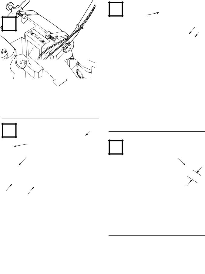
1. Model and serial number engraved in mower housing
Français
1. Numéros de modèle et de série gravés sur le carter de tondeuse
2 |
|
|
|
|
|
|
|
|
|
|
|
English |
|
|
|
1. |
Handle |
3. |
Knobs |
2. |
Mounting bracket |
4. |
Housing pocket |
Français |
|
|
|
1. |
Guidon |
3. |
Boutons seulement |
2. |
Support de montage |
4. |
Poche du carter |
|
|
|
|
3
English
1.Cable tie
2.Throttle cable
Français
1.Serre-câble
2.Câble des gaz
3.*Traction cable (*Self±propelled model)
3.Câble d'embrayage
(modèles autopropulsés)
4 |
5 mm
English
1. Cable tie
Français
1. Serre-câble
EThe Toro Company ± 1997
i |
All Rights Reserved |
|
Printed in USA
5 |
7 |
|
4 |
|
3 |
|
2 |
1 |
1 |
|
|
|
1339 |
English
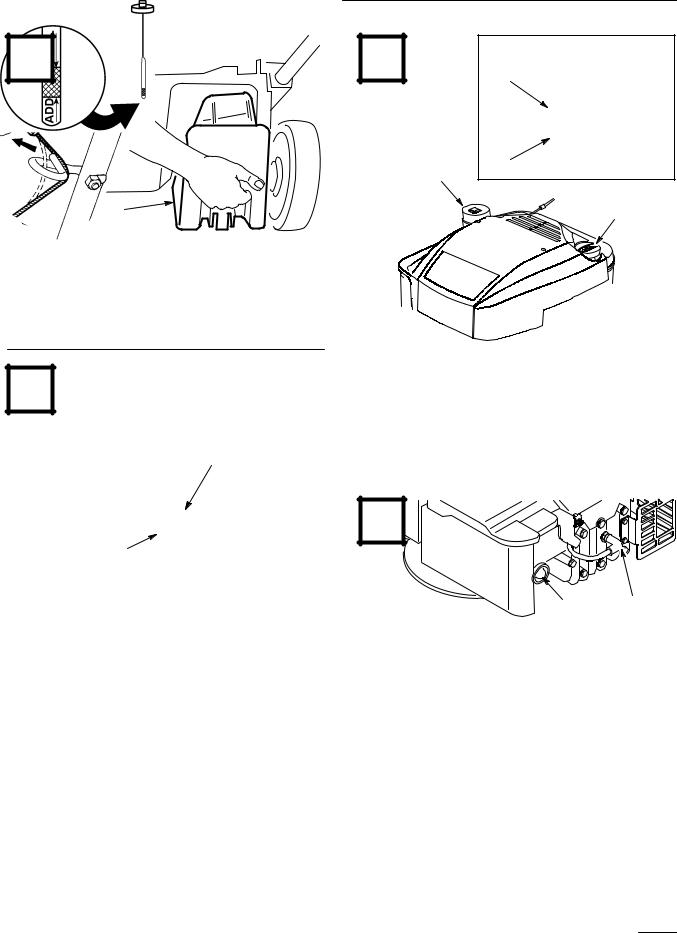
1. Plug
Français
1. Obturateur
1159
6 |
|
English |
|
|
|
1. |
Dipstick |
3. |
ADD mark |
|
2. |
Fuel tank cap |
4. |
FULL mark |
|
|
Français |
|
|
|
1. |
Jauge |
3. |
Repère ADD (ajouter) |
|
2. |
Bouchon du réservoir de |
4. |
Repère FULL (plein) |
|
2 |
|
carburant |
|
|
|
|
|
|
|
8 |
1
|
|
|
M±2950 |
|
|
|
1 |
2 |
1344 |
|
|
|
|
|
|
|
|
|
|
||
English |
|
|
|
English |
|
|
|
|
||
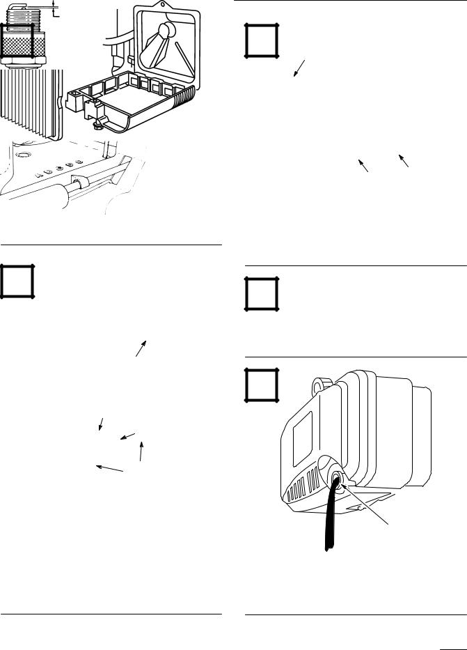
1. |
Rope guide |
2. |
Starter rope |
1. |
Primer |
2. |
Spark plug wire |
|
|
|
Français |
|
|
|
Français |
|
|
|
|
||
1. |
Guide-câble |
2. |
Câble de démarreur |
1. |
Amorceur |
2. |
Fil de bougie |
|
|
|
|
|
|
|
|
|
|
|
|
|
|
ii

9 |
2 |
|
11 |
6 |
|
|
|
|
|
1 |
3 |
|
3 |
|
|
4 |
|
1 |
4 |
|
|
|
|
M±2951 |
|
|
English |
|
|
English |
||
1. |
Throttle |
4. |
Recoil starter |
1. |
Bag door |
2. |
Blade control bar |
* |
Self-propelled model |
2. |
Bag ramp |
3. |
Self-propel control bar* |
|
|
3. |
Discharge door |
Français |
|
|
Français |
||
1. |
Commande des gaz |
4. |
Lanceur |
1. |
Volet du sac |
2. |
Barre de commande de |
* |
modèle autotracté |
2. |
Armature du sac |
|
lame |
|
|
3. |
Volet de décharge |
|
|
|
|
||
3.Barre de commande de traction*
2
 5
5
775
4.Bag handle
5.Mounting bracket
6.Bag frame hook
4.Poignée
5.Support de montage
6.Crochet du cadre du sac
12 |
10 |
1334
1
1339
English
1. Plug
Français
1. Obturateur
iii
13 |
1 |
|
English
1.Sparse/normal grass cutting scale
Français
1.Échelle de coupe pour herbe clairsemée/normale
2
971
2. Lush grass cutting scale
2.Echelle de coupe pour herbe épaisse
15
3
English
1.Cover
2.Screw
Français
1.Capot
2.Vis
2 |
1 |
1003 |
3. Paper filter
3. Filtre en papier
14 |
|
16 |
.030º |
|
|
|
(.76 mm) |
English
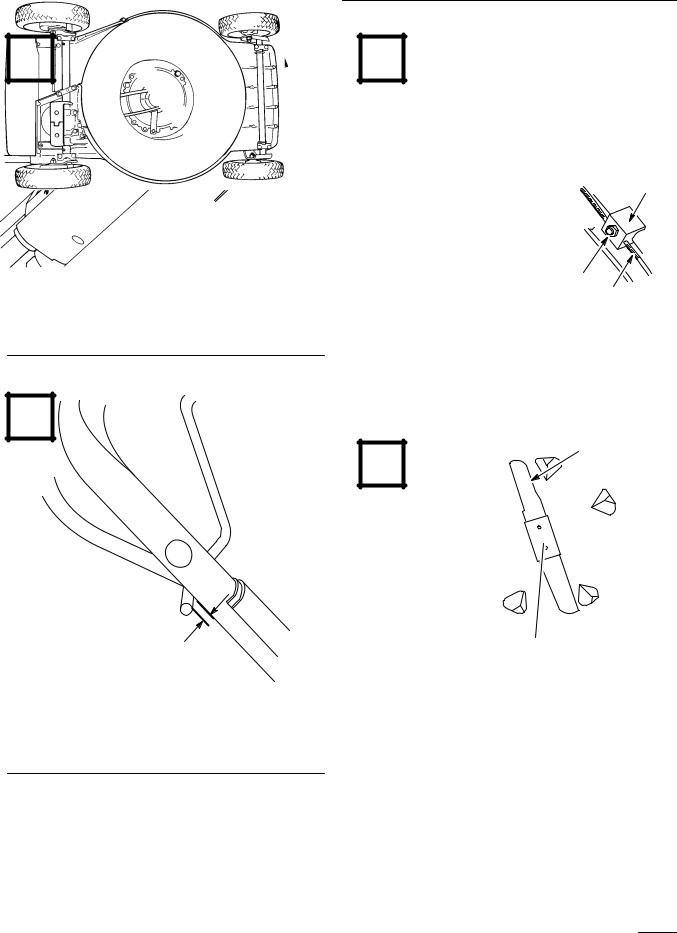
1.Height±of±cut adjustment lever
2.Height settings
Français
1.Levfer de réglage de le hauteur de coupe
2.Hauteurs de coupe
1
17 |
2
|
3 |
|
|
5 |
4 |
|
|
|
|
||
|
|
1336 |
|
3. |
Pointer |
1 |
|
4. |
Link rod |
|
|
5. |
Spring cover |
1782 |
|
|
|
English |
|
3. |
Marqueur |
1. OIl fill tube |
|
4. |
Tige de liaison |
Français |
|
5. |
Capot à ressorts |
||
1. Tube de remplissage d'huile |
|||
|
|
iv

18 |
1
English
1. Drain opening
Français
1. Orifice de vidange
20 |
3 |
4 |
|
|
|
|
|
2 |
1
1328
2348
English |
|
|
|
1. |
Cable clamp screw |
3. |
Throttle lever |
2. |
Throttle cable |
4. |
Stop |
Français |
|
|
|
1. |
Vis du serre-câble |
3. |
Levier d'accélérateur |
2. |
Câble de commande des |
4. |
Butée |
|
gaz |
|
|
|
|
|
|
19 |
2 |
21 |
|
||
|
1 |
|
1329
English
1. |
Cover |
2. |
|
English |
|
Screws (2) |
Adjustment knob |
||||
|
|
|
1. |
||
Français |
|
|
Français |
||
1. |
Capot |
2. |
|
||
Vis (2) |
Bouton de réglage |
||||
|
|
|
1. |
||
|
|
|
|
|
|
22341
2.Control cable
2. Câble de commande
v
22 |
23 |
3,2 mm (1/8º)
Self-propelled model shown
Modèle autotracté représenté
24 |
2
|
|
|
|
3 |
|
2343 |
|
|
|
1 |
2341 |
|
English |
|
|
|
|
1. |
Cable conduit |
3. |
Nut |
|
|
2. |
Cable bracket |
|
|
|
|
|
Français |
|
|
|
|
1. |
Gaîne du câble |
3. |
Ecrou |
|
|
2. |
Support du câble |
|
|
|
|
|
|
|
|
|
|
1
25

 2
2
|
|
|
3 |
1330 |
|
|
|
|
|
||
|
English |
|
|
|
|
M±2948 |
Blade |
3. Blade bolt and lockwasher |
|||
1. |
|||||
2. |
Blade stiffener |
|
|
|
|
|
Français |
|
|
|
|
1. |
Lame |
3. Boulon et rondelle de |
|
|
|
2. |
Renfort de lame |
blocage de la lame |
|
|
|
|
|
|
|||
|
|
|
|
|
|
vi
1
26
A
2
B
3
C
|
|
|
4 |
270 |
English |
|
|
|
|
1. |
Sail |
3. |
Wear |
|
2. |
Flat part of blade |
4. |
Slot formed |
|
Français |
|
|
|
|
1. |
Pale |
3. |
Usure |
|
2. |
Partie plate de la lame |
4. |
Encoche due à l'usure |
|
|
|
|
|
|
27 |
1 |
153
English
1. Sharpen at this angle only
Français
1. Aiguisez à cet angle seulement
28 |
1
1
782
English
1. Grease fitting (self±propelled model)
Français
1. Graisseur (modèles autopropulsès)
29 |
1 3
2
m-2858
English |
|
|
|
1. |
Washout fitting |
3. |
Hose |
2. |
Quick disconnect coupling |
|
|
Français |
|
|
|
1. |
Raccord de rinçage |
3. |
Tuyau d'arrosage |
2. |
Raccord rapide |
|
|
|
|
|
|
30 |
1 |
1330 |
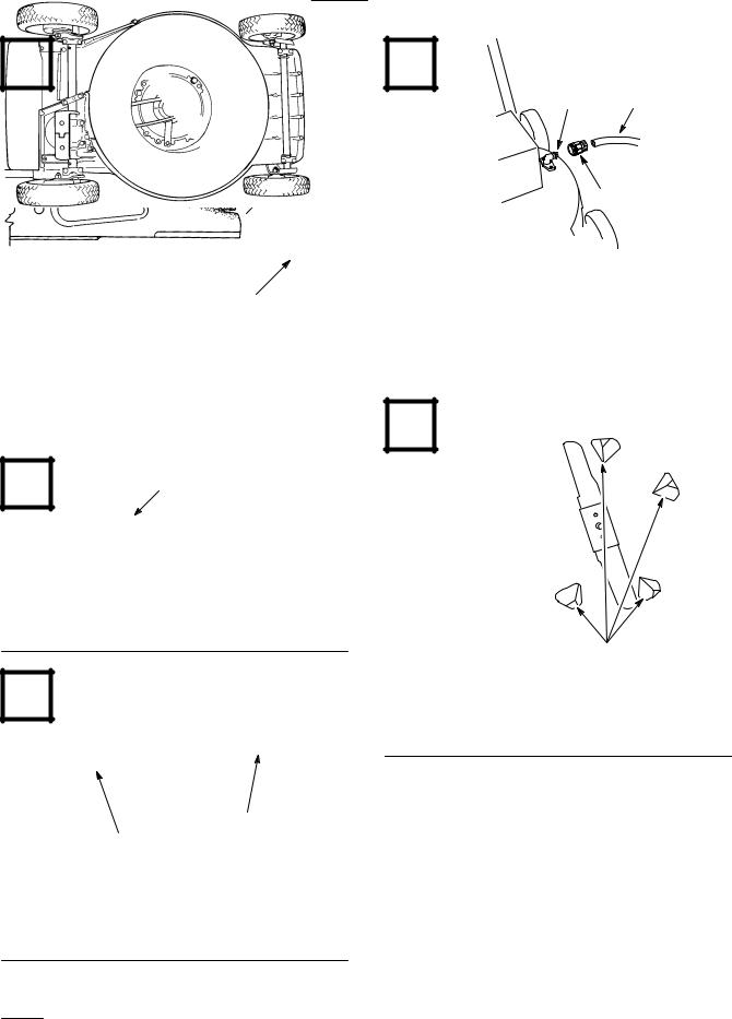
English
1. Kickers
Français
1. Plaques de deflection
vii

Contents |
|
|
Page |
Introduction . . . . . . . . . . . . . . . . . . . . . . . . . . . . |
1 |
Safety . . . . . . . . . . . . . . . . . . . . . . . . . . . . . . . . . |
2 |
Training . . . . . . . . . . . . . . . . . . . . . . . . . . . |
2 |
Preparation . . . . . . . . . . . . . . . . . . . . . . . . . |
2 |
Operation . . . . . . . . . . . . . . . . . . . . . . . . . . |
2 |
Maintenance And Storage . . . . . . . . . . . . . |
3 |
Sound Pressure Level . . . . . . . . . . . . . . . . . |
4 |
Sound Power Level . . . . . . . . . . . . . . . . . . |
4 |
Vibration Level . . . . . . . . . . . . . . . . . . . . . |
4 |
Symbol Glossary . . . . . . . . . . . . . . . . . . . . |
4 |
Assembly . . . . . . . . . . . . . . . . . . . . . . . . . . . . . . |
7 |
Install Handle . . . . . . . . . . . . . . . . . . . . . . . |
7 |
Install Discharge Tunnel Plug . . . . . . . . . . |
7 |
Install Starter Rope . . . . . . . . . . . . . . . . . . |
7 |
Before Starting . . . . . . . . . . . . . . . . . . . . . . . . . . |
7 |
Fill Crankcase With Oil . . . . . . . . . . . . . . . |
7 |
Fill Fuel Tank With Gasoline . . . . . . . . . . . |
8 |
Recycling Tips . . . . . . . . . . . . . . . . . . . . . . . . . . |
9 |
General Tips . . . . . . . . . . . . . . . . . . . . . . . . |
9 |
Cutting Grass . . . . . . . . . . . . . . . . . . . . . . . |
9 |
Cutting Leaves . . . . . . . . . . . . . . . . . . . . . . |
10 |
Operation . . . . . . . . . . . . . . . . . . . . . . . . . . . . . . |
10 |
Starting, Stopping And Self±propelling . . . |
10 |
Using Discharge Tunnel Plug . . . . . . . . . . |
10 |
Using Grass Bag . . . . . . . . . . . . . . . . . . . . . |
11 |
Setting Height-of-Cut . . . . . . . . . . . . . . . . . |
11 |
Maintenance . . . . . . . . . . . . . . . . . . . . . . . . . . . . |
12 |
Servicing Air Cleaner . . . . . . . . . . . . . . . . |
12 |
Replacing Spark Plug . . . . . . . . . . . . . . . . . |
12 |
Draining Gasoline . . . . . . . . . . . . . . . . . . . |
13 |
Changing Crankcase Oil . . . . . . . . . . . . . . |
13 |
Adjusting Throttle . . . . . . . . . . . . . . . . . . . |
14 |
Adjusting Wheel Traction Drive |
|
(self±propelled model) . . . . . . . . . . . . . . |
14 |
Adjusting Brake Cable . . . . . . . . . . . . . . . . |
14 |
Inspecting/Removing/ Sharpening Blade . |
14 |
Lubrication . . . . . . . . . . . . . . . . . . . . . . . . . |
15 |
Cleaning Mower Housing . . . . . . . . . . . . . |
15 |
Storage . . . . . . . . . . . . . . . . . . . . . . . . . . . . . . . . |
16 |
Introduction
Thank you for purchasing a Toro product.
All of us at Toro want you to be completely satisfied with your new product, so feel free to contact your local Authorized Service Dealer for help with service, genuine Toro parts, or other information you may require.
Whenever you contact your Authorized Service Dealer or the factory, always know the model and serial numbers of your product. These numbers will help the Service Dealer or Service Representative provide exact information about your specific product. You will find the model and serial number decal located in a unique place on the product
(Fig. 1).
For your convenience, write the product model and serial numbers in the space below.
Model No:
Serial No.
Read this manual carefully to learn how to operate and maintain your product correctly. Reading this manual will help you and others avoid personal injury and damage to the product. Although Toro designs, produces and markets safe, state-of-the-art products, you are responsible for using the product properly and safely. You are also responsible for training persons who you allow to use the product about safe operation.
The Toro warning system in this manual identifies potential hazards and has special safety messages that help you and others avoid personal injury, even death. DANGER, WARNING and CAUTION are signal words used to identify the level of hazard. However, regardless of the hazard, be extremely careful.
DANGER signals an extreme hazard that will cause serious injury or death if the recommended precautions are not followed.
GB±1

WARNING signals a hazard that may cause serious injury or death if the recommended precautions are not followed.
CAUTION signals a hazard that may cause minor or moderate injury if the recommended precautions are not followed.
Two other words are also used to highlight information. ªImportantº calls attention to special mechanical information and ªNoteº emphasizes general information worthy of special attention.
The left and right side of the machine is determined by standing behind the handle in the normal operator's position.
Safety
Training
1.Read the instructions carefully. Be familiar with the controls and the proper use of the equipment.
2.Never allow children or people unfamiliar with these instructions to use the lawnmower. Local regulations may restrict the age of the operator.
3.Never mow while people, especially children, or pets are nearby.
4.Keep in mind that the operator or user is responsible for accidents or hazards occurring to other people or their property.
Preparation
1.While mowing, always wear substantial footwear and long trousers. Do not operate the equipment when barefoot or wearing open sandals.
2.Always wear safety glasses or eye shields during operation to protect eyes from foreign objects that may be thrown from the machine. Wearing of hearing protection, protective gloves and a safety helmet is advisable.
3.Thoroughly inspect the area where the equipment is to be used and remove all objects which may be thrown by the machine.
4.WARNING ± Petrol is highly flammable.
•Store fuel in containers specifically designed for this purpose.
•Refuel outdoors only and do not smoke while refuelling.
•Add fuel before starting the engine. Never remove the cap of the fuel tank or add petrol while the engine is running or when the engine is hot.
•If petrol is spilled, do not attempt to start the engine but move the machine away from the area of spillage and avoid creating any source of ignition until petrol vapors have dissipated.
•Replace all fuel tanks and container caps securely.
5.Replace faulty silencers.
6.Before using, always visually inspect to see that the blades, blade bolts and cutter assembly are not worn or damaged. Replace worn or damaged blades and bolts in sets to preserve balance.
7.On multi-bladed machines, take care as rotating one blade can cause other blades to rotate.
Operation
1.Do not operate the engine in a confined space where dangerous carbon monoxide fumes can collect.
2.Mow only in daylight or in good artificial light.
3.Avoid operating the equipment in wet grass, where feasible.
4.Always be sure of your footing on slopes.
5.Walk, never run.
6.For wheeled rotary machines, mow across the face of slopes, never up and down.
GB±2
7.Exercise extreme caution when changing direction on slopes.
8.Do not mow excessively steep slopes.
9.Use extreme caution when reversing or pulling the lawnmower towards you.
10.Stop the blade(s) if the lawnmower has to be tilted for transportation when crossing surfaces other than grass, and when transporting the lawnmower to and from the area to be mowed.
11.Never operate the lawnmower with defective guards or shields, or without safety devices, for example deflectors and/or grass catchers, in place.
12.Do not change the engine governor settings or overspeed the engine.
13.Disengage all blade and drive clutches before starting the engine.
14.Start the engine or switch on the motor carefully according to instructions and with feet well away from the blade(s).
15.Do not tilt the lawnmower when starting the engine or switching on the motor, except if the lawnmower has to be tilted for starting. In this case, do not tilt it more than absolutely necessary and lift only the part which is away from the operator.
16.Do not start the engine when standing in front of the discharge chute.
17.Do not put hands or feet near or under rotating parts. Keep clear of the discharge opening at all times.
18.Never pick up or carry a lawnmower while the engine is running.
19.Stop the engine and disconnect the spark plug wire.
•before clearing blockages or unclogging chute;
•before checking, cleaning or working on the lawnmower;
•after striking a foreign object. Inspect the lawnmower for damage and make repairs before restarting and operating the lawnmower;
•if lawnmower starts to vibrate abnormally (check immediately).
20. Stop the engine
•whenever you leave the lawnmower;
•before refuelling.
21.Reduce the throttle setting during engine shut down and, if the engine is provided with a shut-off valve, turn the fuel off at the conclusion of mowing.
22.Go slow when using a trailing seat.
Maintenance And Storage
1.Keep all nuts, bolts and screws tight to be sure the equipment is in safe working condition.
2.Never store the equipment with petrol in the tank inside a building where fumes may reach an open flame or spark.
3.Allow the engine to cool before storing in any enclosure.
4.To reduce the fire hazard, keep the engine, silencer, battery compartment and petrol storage area free of grass, leaves, or excessive grease.
5.Check the grass catcher frequently for wear or deterioration.
6.Replace worn or damaged parts for safety.
7.If the fuel tank has to be drained, this should be done outdoors.
GB±3

Sound Pressure Level
Model 20804
This unit has an equivalent continuous A-weighted sound pressure at the operator ear of: 83 dB(A), based on measurements of identical machines per ANSI B71.5-1984 procedures.
Model 20809
This unit has an equivalent continuous A-weighted sound pressure at the operator ear of: 82 dB(A), based on measurements of identical machines per ANSI B71.5-1984 procedures.
Vibration Level
Model 20804
This unit has a maximum hand-arm vibration level of 9.4 m/s@, based on measurement of identical machines per ISO 5349 procedures.
Model 20809
This unit has a maximum hand-arm vibration level of 5.5 m/s@, based on measurement of identical machines per ISO 5349 procedures.
Sound Power Level
This unit has a sound power level of: 96 dB(A)/1 pW, based on measurements of identical machines per Directive 84/538/EEC and amendments.
Symbol Glossary
Safety alert triangle Ð symbol within triangle indicates a hazard.
Safety alert symbol
Read operator's manual.
Consult technical manual for proper service procedures.
Stay a safe distance from the machine.
Do not open or remove safety shields while engine is running.
Rotating blade can cut off toes or fingers. Stay clear of mower blade as long as engine is running.
To avoid blade failure when mulching, use blade stiffener when mower is equipped with mulching plug.
Transmission
Oil
GB±4

Stay a safe distance from the mower.
Throw or flying objects Ð Whole body exposure
Thrown or flying objects Ð Rotary side-mounted mower. Keep deflector shield in place.
Stop engine before leaving operator position.
Hourmeter/elapsed operating hours
Fast
Slow
Decreasing/Increasing
Grease lubrication point
On/Run
Engage
Disengage
Battery charging condition
Fuel
Neutral
First gear
Second gear
Third gear
GB±5

Engine start
Engine stop
Choke
Primer (start aid)
Push primer three times.
Properly dispose of batteries.
Insert key in ignition switch.
Turn key in ignition switch.
Move control.
Cutting element Ð basic symbol
Cutting element Ð height adjustment
Pull rope.
Wheel
Wheel traction
Lower control bar.
Raise control bar.
Raise/lower control bar.
Raise/lower control bar.
GB±6
 Loading...