

Toro 20805, 20812 Parts Catalogue
48cm Recycler
Walk Power Lawn Mower
Model No. 20805–200000001 and Up
Model No. 20812–200000001 and Up
Form No. 3323–132
Parts Catalog
Ordering Replacement Parts
To order replacement parts, please supply: the part
number, the quantity, and the description of each
part desired.
Understanding Reference Numbers
Each identified part in an illustration has a reference
number. The reference number for a part also appears in
the parts list, along with other information about the part.
This catalog uses two special reference number formats,
one to indicate parts in a service assembly and another
to indicate the quantity of a given part in an illustration.
Service Assembly Reference Numbers
Parts in service assemblies have reference numbers in
the form a:b.
the entire service assembly and the b represents a
sequential number unique to each part within the service
assembly.
The a represents the reference number of
The TORO Company — 2000
All Rights Reserved
For example, a wheel assembly might be identified by
reference number 6, the tire by 6:1, the valve by 6:2,
and the wheel by 6:3. When you order the assembly
identified by reference number 6, you receive all parts
identified by reference numbers 6:1, 6:2, and 6:3.
However, you may also order any part individually.
Reference numbers of this type appear in illustrations
and in part lists.
Reference Numbers Indicating Quantity
In an illustration, if a reference number indicates more
than one part, the reference number has the form nX y.
The n represents the quantity of the part, the X is the
multiplication symbol, and the y represents the reference
number.
For example, in an illustration, the reference number
2X 37 means that two of the parts identified by reference
number 37 are indicated.

3323–132
Contents
Description Page Description Page
Deck, Kickers, & Recycler Plug Assembly 3. . . . . .
Engine & Blade Assembly 4. . . . . . . . . . . . . . . . . . . .
HOC & Wheel Assembly 5. . . . . . . . . . . . . . . . . . . . .
Lower Handle Assembly 6. . . . . . . . . . . . . . . . . . . . .
HP Handle Assembly 7. . . . . . . . . . . . . . . . . . . . . . . .
Rear Bagging Assembly 8. . . . . . . . . . . . . . . . . . . . . .
Axle Assembly 9. . . . . . . . . . . . . . . . . . . . . . . . . . . . . .
Engine Briggs & Stratton
Model 12F802–1769–B1 10–18. . . . . . . . . . . . . . .
Maintenance 19. . . . . . . . . . . . . . . . . . . . . . . . . . . . . . .
Accessories
Description Model / Part No. Description Model / Part No.
Part Description Abbreviations
Part descriptions in this catalog may include the following abbreviations.
Abbreviation Meaning Abbreviation Meaning
AR as required. . . . . . . . . . . . . . . . .
ASM assembly. . . . . . . . . . . . . . . .
CARR carriage. . . . . . . . . . . . . .
DEG degrees. . . . . . . . . . . . . . . .
FH flat head. . . . . . . . . . . . . . . . .
GA gauge. . . . . . . . . . . . . . . . .
HF hex flange. . . . . . . . . . . . . . . . .
HH hex head. . . . . . . . . . . . . . . . .
HHF hex head flange. . . . . . . . . . . . . . . .
HLH hex lag head. . . . . . . . . . . . . . . .
HJ hex jam. . . . . . . . . . . . . . . . . .
HOC height-of-cut. . . . . . . . . . . . . . . .
HS hex socket. . . . . . . . . . . . . . . . .
HSBH hex socket button head. . . . . . . . . . . . . .
HSFH hex socket flat head. . . . . . . . . . . . . . .
HSH hex socket head. . . . . . . . . . . . . . . .
HWH hex washer head. . . . . . . . . . . . . . .
HWHTF hex washer head. . . . . . . . . . . . .
thread forming
INC incorporated. . . . . . . . . . . . . . . . .
LH left hand. . . . . . . . . . . . . . . . .
NI nylon insert. . . . . . . . . . . . . . . . . .
PPH Phillips pan head. . . . . . . . . . . . . . . .
PTH Phillips truss head. . . . . . . . . . . . . . . .
PTO power take off. . . . . . . . . . . . . . . .
RH right hand. . . . . . . . . . . . . . . . .
SFH slotted fillister head. . . . . . . . . . . . . . . .
SHH slotted hex head. . . . . . . . . . . . . . . .
SQH square head. . . . . . . . . . . . . . . .
SHWH slotted hex washer head. . . . . . . . . . . . . .
SPH slotted pan head. . . . . . . . . . . . . . . .
SRH slotted round head. . . . . . . . . . . . . . . .
STD standard. . . . . . . . . . . . . . . .
TAP self tapping. . . . . . . . . . . . . . . .
TTH Torx truss head. . . . . . . . . . . . . . . .
WH wing head. . . . . . . . . . . . . . . . .
2
20
21
3323–132
7
1
1:2
18
17
16
15
7
19
14
13
3
4
5
6
7
9
10
24
11
12
22
7
7
Sheet No.:2
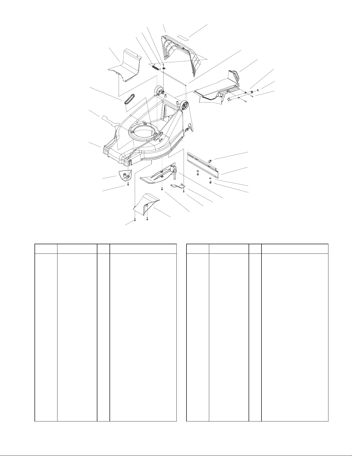
Deck, Kickers, & Recycler Plug Assembly
DescriptionPart No. Qty.Ref. No. DescriptionPart No. Qty.Ref. No.
1 100–9115 1 Door–Decal ASM
1:2 93–4105 1 Decal – Danger
3 100–1509 1 Rod–Pivot, Door
4 100–1505 1 Recycler–Plug, Kicker
5 100–1522 1 Fitting–Washout
6 46–6290 1 O–Ring
7 32144–1 11 Screw–Taptite
9 2412–87 2 Clamp–Cable
10 100–4367 1 Shield–Trailing
11 49–2040 2 Screw–Taptite
12 99–6486 1 Kicker–Cover, Rear
13 100–1506 1 Ramp–Discharge
14 100–4352 2 Screw–HWH
15 99–6485 1 Kicker–Front
16 99–6457–01 1 Deck
17 100–9120 1 Decal–Deck (only on:
20812)
17 100–4354 1 Decal–Recycler (only
on: 20805)
18 100–3932 1 Boot–HOC
19 99–6479 1 Belt Cover
20 99–5293 1 Spring–Torsion
21 98–2256 2 Clamp
22 100–9123–03 1 Bracket–Deck
24 3256–22 4 Washer–Flat
3
3323–132
16
13
18
17
19
1
2
4
5
12
11
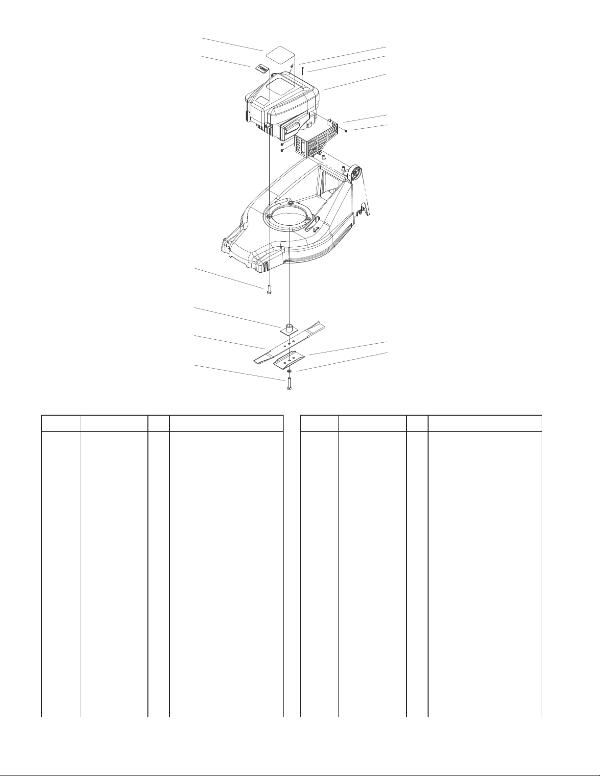
Engine & Blade Assembly
DescriptionPart No. Qty.Ref. No. DescriptionPart No. Qty.Ref. No.
1 32144–121 2 Screw–PPH
2 93–0243 1 Shroud–Quantum
Wedge
4 82–8550–03 1 Shield–Muffler
5 32144–73 3 Screw–HWH
9 80–0510–03 1 Blade Stiffener
10 3253–22 1 Washer–Lock/Sp
11 100–4368 1 Bolt–Blade
12 71–9260–03 1 Blade
13 99–6467 1 Blade Driver ASM
16 32144–102 3 Screw–HWH
17 92–2289 1 Plate–Logo
18 100–5952 1 Decal–Engine (only
on: 20805)
18 100–9122 1 Decal–Engine (only
on: 20812)
19 2210–316 1 Stop–Rope
*20 99–0905 1 Guard–Flywheel
*21 32144–4 1 Screw–HH
9
10
Sheet No.:3
* Not illustrated
4
3323–132
1
25
24
23
24:2
27
12
2
3
4
5
6
8
9
10
11
13
14
1
15
16
17
18
19
22
8
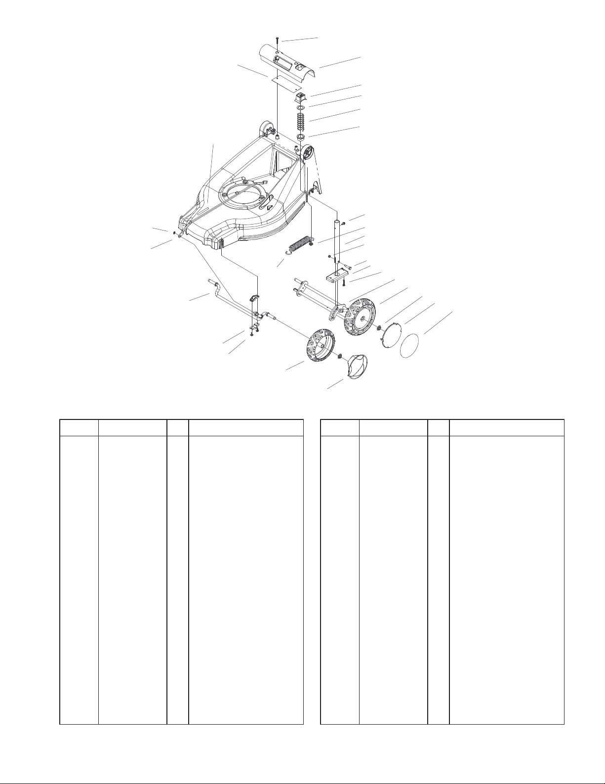
HOC & Wheel Assembly
DescriptionPart No. Qty.Ref. No. DescriptionPart No. Qty.Ref. No.
1 100–4352 4 Screw–HWH
2 99–6487 1 Handle–Deck
3 99–6480 1 Button–HOC
4 88–7540 1 Washer – Backup
5 99–6481 1 Spring–Compression,
HOC
6 99–6483 1 Bushing–HOC
8 32144–1 5 Screw–Taptite
9 92–9698 1 Screw–Shoulder
10 99–6458 1 Pipe – HOC
11 3296–73 1 Nut–Lock, NI
12 100–4384 1 Spring–Extension,
HOC
13 99–6459 1 Bolt–Shoulder
14 99–6460 1 Plate–Support, HOC
15 99–6478 1 Axle–Rear ASM
16 100–1516 2 Wheel ASM
17 100–4370 4 Nut–Lock, Flanged
18 100–4366 2 Cover–Smart Wheel
19 100–9114 2 Decal–Smart Wheel
20 95–6543 2 Cover – Wheel
21 99–6470 2 Wheel ASM
22 100–1500 4 Mount–Axle, Front
23 99–6464 1 Axle–Front ASM
24 100–9116 1 Rod–Decal ASM
24:2 100–4355 1 Decal–HOC
21
Sheet No.:4
20
25 100–3939 2 Palnut
27 100–4383–03 1 Cover–Handle
5
3323–132
20
13
12
14
19
18
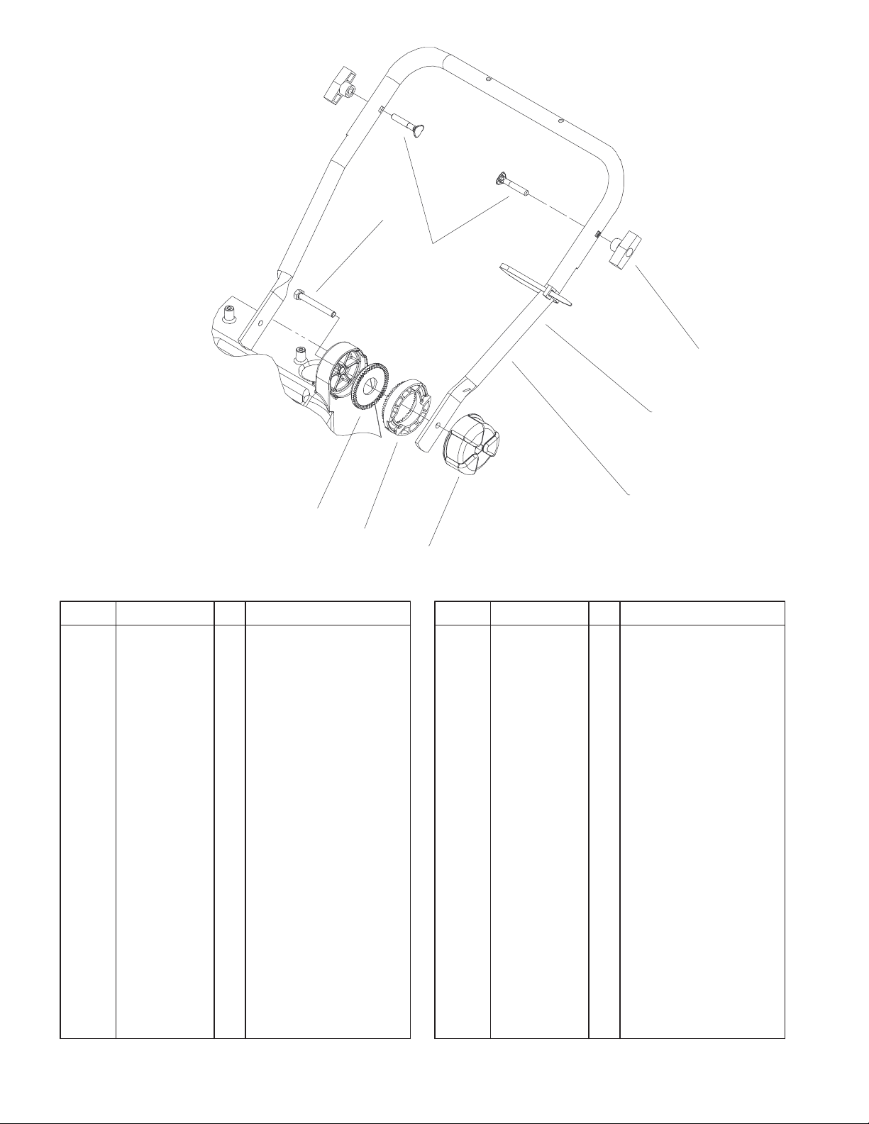
Lower Handle Assembly
DescriptionPart No. Qty.Ref. No. DescriptionPart No. Qty.Ref. No.
12 98–7134 2 Knob–Handle
13 92–2260 2 Screw–Handle
14 3290–378 2 Tie–Cable
15 100–1502–05 1 Handle–Lower
17 100–4396 2 Adjusting
Knob–Handle
18 100–1510 2 Disk Adjusting–Handle
19 100–1517 2 Disk Holding–Handle
20 60–6690 2 Capscrew
15
Sheet No.:5
17
6
 Loading...