

Page 1

LAWN-BOY V-ENGINE SERVICE MANUAL
Table of Contents – Page 1 of 2
REFERENCE SECTION
SAFETY
SPECIFICATIONS - ENGINE SPECIFICATIONS
SPECIFICATIONS - ENGINE FASTENER TORQUE REQUIREMENTS
SPECIFICATIONS - CARBURETOR SPECIFICATIONS (WALBRO LMR-16)
SPECIAL TOOL REQUIREMENTS
TROUBLESHOOTING
MAINTENANCE
SECTION 1 WALBRO LMR-16 CARBURETOR
LMR-16 CARBURETOR - IDENTIFICATION
LMR-16 CARBURETOR - THEORY OF OPERATION
LMR-16 CARBURETOR - GOVERNOR THEORY
LMR-16 CARBURETOR - REMOVAL
LMR-16 CARBURETOR - DISASSEMBLY
LMR-16 CARBURETOR - CLEANING AND INSPECTION
LMR-16 CARBURETOR - ASSEMBLY
LMR-16 CARBURETOR - PRESETTING THE GOVERNOR
LMR-16 CARBURETOR - ASSEMBLING AIR BOX TO CARBURETOR
LMR-16 CARBURETOR - INSTALLATION
LMR-16 CARBURETOR - FINAL CHECK
LMR-16 CARBURETOR - CHOKE ADJUSTMENT
LMR-16 CARBURETOR - SERVICING THE AIR FILTER
LMR-16 CARBURETOR-TROUBLESHOOTING
SECTION 2 PRIMER START CARBURETOR
PRIMER START CARBURETOR - IDENTIFICATION
PRIMER START CARBURETOR - THEORY OF OPERATION
PRIMER START CARBURETOR - GOVERNOR THEORY
PRIMER START CARBURETOR - REMOVAL
PRIMER START CARBURETOR - DISASSEMBLY
PRIMER START CARBURETOR - CLEANING AND INSPECTION
PRIMER START CARBURETOR - ASSEMBLY
PRIMER START CARBURETOR - INSTALLATION
PRIMER START CARBURETOR - PRESETTING THE GOVERNOR
PRIMER START CARBURETOR - FINAL CHECK
PRIMER START CARBURETOR - SERVICING THE AIR FILTER
PRIMER START CARBURETOR TROUBLESHOOTING
ENGINE STARTS HARD
ENGINE RUNS RICH
ENGINE RUNS LEAN
FUEL LEAKS FROM CARBURETOR
Page 2

LAWN-BOY V-ENGINE SERVICE MANUAL
Table of Contents – Page 2 of 2
SECTION 3 FUEL SYSTEM
FUEL SYSTEM - OPERATION
FUEL SYSTEM - CAP SERVICE
FUEL SYSTEM - TANK REMOVAL
FUEL SYSTEM - CLEANING
FUEL SYSTEM - TANK INSTALLATION
SECTION 4 IGNITION SYSTEM
IGNITION SYSTEM - TROUBLESHOOTING
IGNITION SYSTEM - SPARK PLUG OPERATION
IGNITION SYSTEM - SPARK PLUG SERVICE
IGNITION SYSTEM - CD PACK OPERATION
IGNITION SYSTEM - CD PACK AIR GAP ADJUSTMENT
IGNITION SYSTEM - CD PACK REMOVAL/INSTALLATION
IGNITION SYSTEM - FLYWHEEL OPERATION
IGNITION SYSTEM FLYWHEEL REMOVAL
IGNITION SYSTEM - FLYWHEEL INSTALLATION
SECTION 5 REWIND STARTER
REWIND STARTER - OPERATION
REWIND STARTER - REMOVAL AND DISASSEMBLY
REWIND STARTER - REASSEMBLY
SECTION 6 ENGINE
ENGINE - DESCRIPTION
ENGINE - THEORY OF OPERATION
ENGINE - SERVICE TIPS
ENGINE - REMOVAL
ENGINE - DISASSEMBLY
ENGINE - INSPECTION AND REPAIR
ENGINE - REED VALVE SERVICE
ENGINE - REASSEMBLY
SECTION 7 PIVOTING ZONE START BRAKE
INTRODUCTION
PIVOTING ZONE START BRAKE - OPERATION
PIVOTING ZONE START BRAKE - DISASSEMBLY
PIVOTING ZONE START BRAKE - ASSEMBLY
APPENDIX A
Page 3
V-Engine
Page 4
Reference Section
TABLE
OF
CONTENTS
Service Section
Safety Information
Engine Specifications 10
Engine Fastener Torque Requirements 11
Carburetor Specifications 12
Special Tool Requirements 13
Troubleshooting 14
Maintenance 19
Recommended Maintenance Schedule 19
Air Filter 19
Spark Plug 20
Cleaning the Exhaust System 21
9
Section 1 LMR-16
Identification 25
Theory of Operation 25
Governor Theory 25
Removal 26
Disassembly 27
Cleaning and Inspection 27
Assembly 28
Presetting the Governor 29
Assembling Air Box to Carburetor 29
Installation 30
Final Check 30
Choke Adjustment 30
Servicing the Air Filter
Carburetor
30
V-Engine
Troubleshooting 31
3
Table
of
Contents
Page 5
Service Section (cont'd)
TABLE
OF
CONTENTS
Section
2
Primer Start Carburetor
Identification 32
of
Theory
Governor The0
Removal 33
Disassembly 34
Cleaning and Inspection 34
Assembly 34
Installation 35
Presetting the Governor 35
Final Check 35
Servicing the Air Filter 36
Troubleshooting 36
Operation 32
ry
32
Section 3
Section 4
Fuel System
Operation 37
Cap Service 37
Tank Removal 38
Cleaning 38
installation
Tank
Ignition System
Troubleshooting 39
Spark Plug
Operation 39
Service 39
38
V-Engine
Table
of
Contents
Page 6
Service Section (cont’d)
Section 4 (cont’d)
CD Pack
Flywheel
TABLE
Operation 40
Air Gap Adjustment 41
Removal Installation 41
Operation 41
Removal 41
Installation 42
OF
CONTENTS
Section
Section 6
5
Rewind Starter
Operation 43
Removal and Disassembly 43
Reassembly 44
Engine
Description
Theory
Service Tips
Removal ..............................................................................................................
Disassembly ........................................................................................................
of
Operation ............................................................................................
........................................................................................................
Inspection and Repair
Reed Valve Service
..............................................................................
..................................................................................
.........................................................
Reassembly .........................................................................................................
V-Engine Table
of
Contents
Page 7
Service Section (cont’d)
TABLE
OF
CONTENTS
Section
Appendix A
7
Pivoting Zone Start Brake
Introduction
Operation
Disassembly 53
Assembly
Exploded View Diagrams A-1
53
53
54
Table
of
Contents
6
V-Engine
Page 8
SAFETY INFORMATION
This safety symbol means WARNING or PERSONAL SAFETY INSTRUCTION read the instruction
because it has to do with your safety. Failure to comply with the instruction may result in personal injury
or even death.
This manual is intended as a service and repair manual only. The safety instructions provided herein are for troubleshooting, service and repair of the engine only. The individual Operator’s manual will contain safety information
V
on the complete product powered by the
through:
Lawn-Boy Corporation
Publications Department
8111
Lyndale Avenue South
MN
Bloomington,
55430
engine. Operator’s manuals with complete instructions are available
U.S.A.
SAFETY TIPS
Avoid unexpected starting of engine
Always turn
spark plug wire before attempting cleaning, adjustment or repair.
Avoid lacerations and amputations
Stay clear of all moving parts whenever the engine is
running. Treat all normally moving parts as
were moving whenever the engine
the potential to start.
Avoid burns
Do
not touch the engine while it is running or shortly
after it has been running.
Avoid Falls
Do not operate the powered product on slippery surfaces or
Avoid fires
Wipe up any spilled fuel or oil immediately.
off
the powered product and disconnect
if
footing is questionable.
if
they
is
running or has
Avoid asphyxiation
Never operate an engine in a confined area without
proper ventilation.
Avoid fires and explosions
Use a container designed for gasoline. Avoid spilling
fuel and never smoke while working with any type of
fuel.
Avoid accidental misuse of fuel
Always stole fuel in a properly labeled container
designed for gasoline.
Avoid injury due to inferior parts
Use only Lawn-Boy@ original parts to ensure that
important safety criteria are met.
Avoid
Always clear the area of bystanders before starting or
testing powered equipment.
Avoid injury due
Always clear the area of sticks, rocks or any other
debris that could be picked up and thrown by the
powered equipment.
injury to bystanders
to
projectiles
Reference Section
9
Safety Information
Page 9
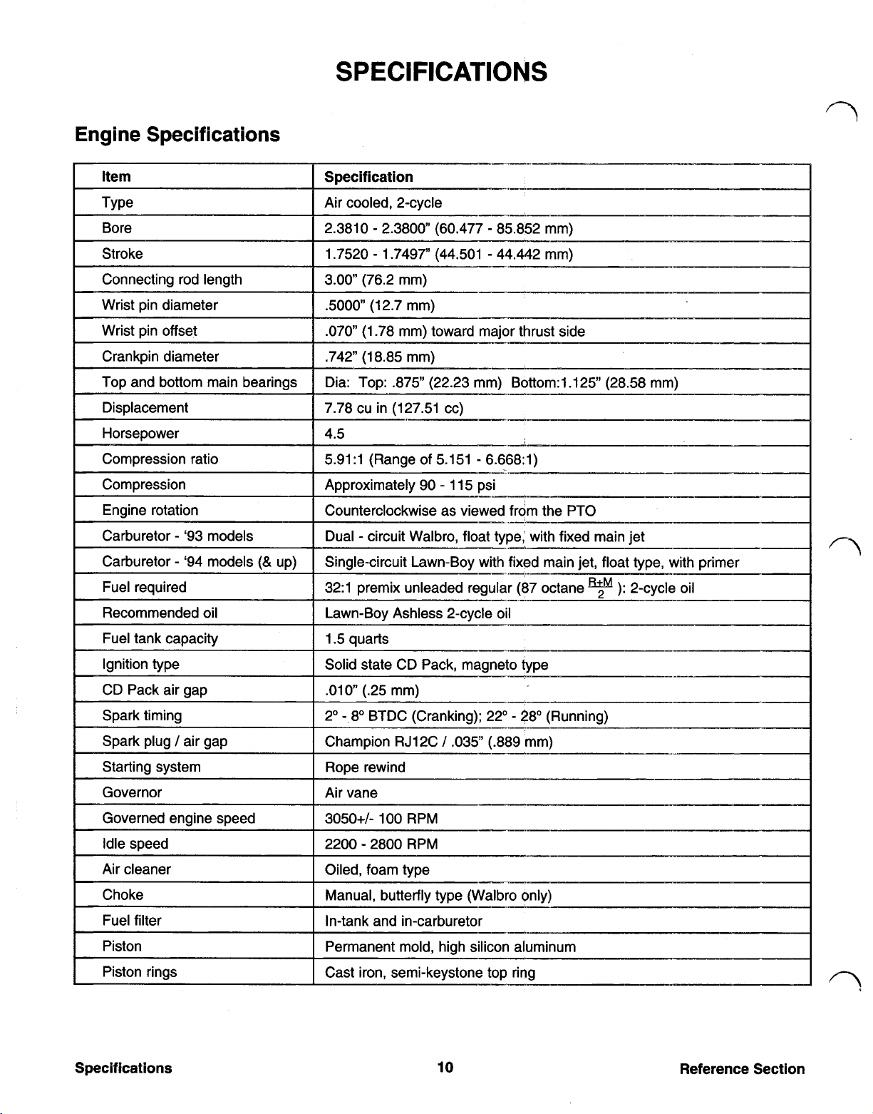
Engine Specifications
Bore 2.3810 2.3800 (60.477 85.852 mm)
Stroke 1.7520 1.7497” (44.501 44.442 mm)
Connecting rod length 3.00 (76.2 mm)
Wrist pin diameter
Wrist pin offset
Crankpin diameter
Top and bottom main bearings Dia: Top: .875” (22.23 mm) Bottom:1.125” (28.58 mm)
Displacement
Horsepower
Compression ratio 5.91:l (Range of 5.151 6.668:l)
Carburetor ‘93 models
Carburetor ‘94 models up)
Fuel required
Recommended oil
Fuel tank capacity
Ignition type
CD Pack air gap
Spark timing
.5000”
.070
.742” (18.85 mm)
7.78 cu in (127.51 cc)
4.5
Dual circuit Walbro, float type,’ with fixed main jet
Single-circuit Lawn-Boy with fixed main jet, float type, with primer
32:l premix unleaded regular (87 octane 2-cycle oil
Lawn-Boy Ashless 2-cycle oil
1.5 quarts
Solid state CD Pack, magneto type
.010 (.25 mm)
2’ 8’ BTDC (Cranking); 22’ 28’ (Running)
(12.7 mm)
(1.78 mm) toward major thrust side
__-
--_-
Spark plug air gap Champion RJ12C .035 (.889 mm)
Starting system
Governor Air vane
Governed engine speed
Idle speed
Air cleaner
Choke
Fuel filter
Piston Permanent mold, high silicon aluminum
Piston rings Cast iron, semi-keystone top ring
Rope rewind
3050+/- 100 RPM
2200 2800 RPM
Oiled, foam type
Manual, butterfly type (Walbro only)
ln-tank and in-carburetor
10
Reference Section
Page 10

SPECIFICATIONS
Engine Fastener Torque Requirements
Torque
(cont'd)
45 50
375 425
5
60 70
45
90 110
105 115
300 350
15 25
150 190
140 200
10 13
65 75
58 70
60 70
150 200
65.15
7
in
55 in
ft
Ibs
in
Ibs
(.5 .8 N-m)
in
Ibs
Ibs
in
Ibs
in
in
in
Ibs
in
in
in
Ibs
in
Ibs
in
Ibs
in
Ibs
in
in
Ibs
(60 67 N-m)
lbs
(42 47 N-m)
(6.7 7.8 N-m)
(5.0 6.1 N-m)
(10 12 N-m)
Ibs
(12 13 N-m)
Ibs
(34 39 N-m)
(1.7 2.8 N-m)
Ibs
(17 22 N-m)
Ibs
(16 22 N-m)
(1.1 1.5 N-m)
(7.3 8.4 N-m)
(6.5 7.8 N-m)
_I
(6.7 7.8 N-m)
Ibs
(17 23 N-m)
(7.3 8.4 N-m)
-__I_-----~-
* Use thread-locking compound
Reference Section
11
Specifications
Page 11
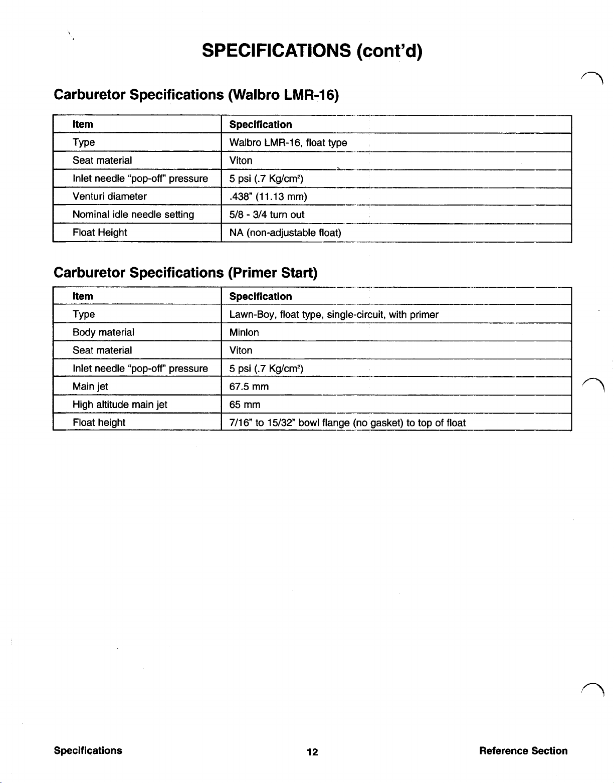
SPECIFICATIONS
Carburetor Specifications (Walbro LMR-16)
Carburetor Specifications (Primer Start)
(cont’d)
12
Reference Section
Page 12
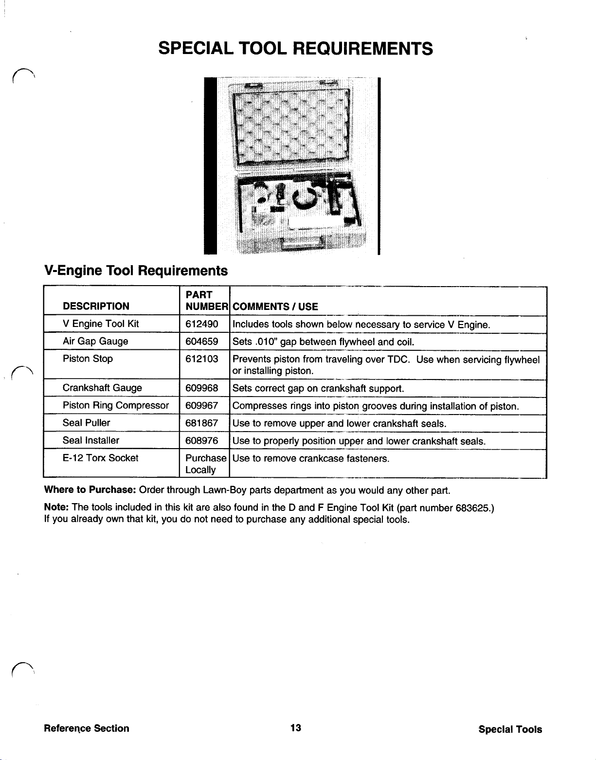
SPECIAL TOOL REQUIREMENTS
V-Engine
DESCRIPTION
V
Engine Tool Kit 612490
Air Gap Gauge 604659
Piston Stop 61 21 03
Crankshaft Gauge 609968
Piston Ring Compressor 609967
E-12
Where
Note:
If
to
The tools included in this kit are also found in the D and F Engine Tool Kit (part number 683625.)
you already own that kit, you do not need to purchase any additional special tools.
Tool
Torx
Socket Purchase
Purchase:
Requirements
Includes tools shown below necessary to service
Sets .010” gap between flywheel and coil.
Prevents piston from traveling over TDC. Use when servicing flywheel
or installing piston.
Sets correct gap on crankshaft support.
Compresses rings into piston grooves during installation of piston.
Use to remove upper and lower crankshaft seals.
Use to properly position upper and lower crankshaft seals.
Use to remove crankcase fasteners.
Locally
Order through Lawn-Boy parts department as you would any other part.
__-
.-
V
Engine.
Reference Section
13
Special Tools
Page 13
Contents
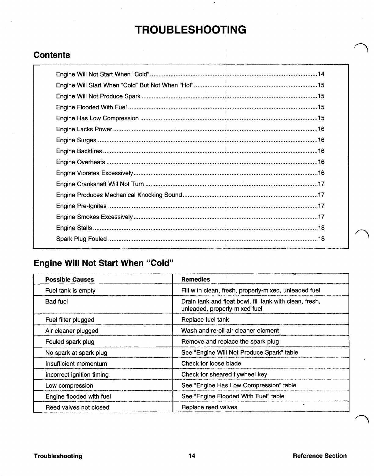
TROUBLESHOOTING
Engine Will Not Start When “Cold
Engine Will Start When “Cold But Not When “Hot”
Engine Will Not Produce Spark
Engine Flooded With Fuel
Engine Has Low Compression
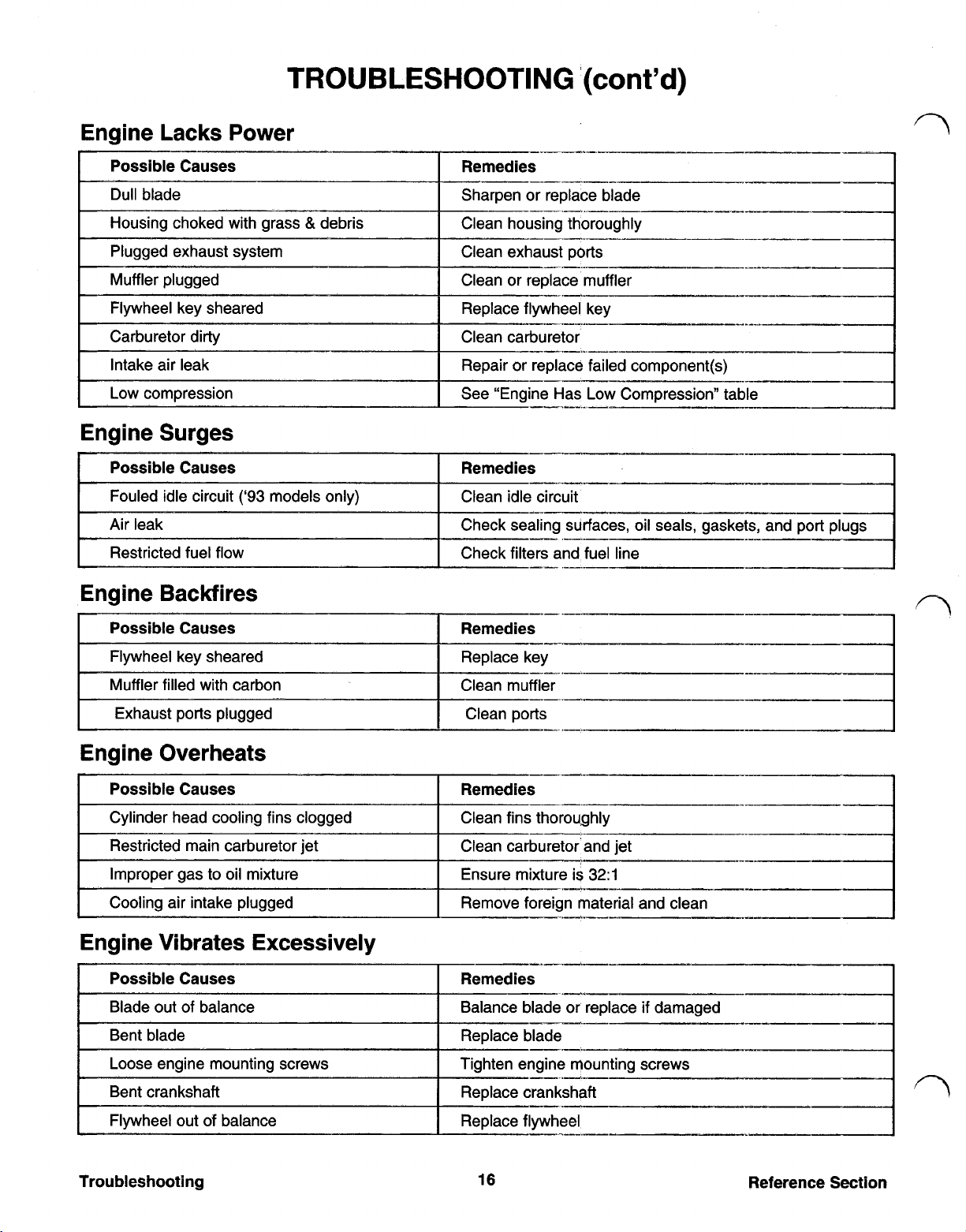
Engine Lacks Power
Engine Surges
Engine Backfires
Engine Overheats
Engine Vibrates Excessively
Engine Crankshaft Will Not Turn
Engine Produces Mechanical Knocking Sound
Engine Pre-Ignites
Engine Smokes Excessively
Engine Stalls
Spark Plug Fouled
......................................................
14
15
15
15
15
16
16
16
I6
16
17
17
17
17
.I8
18
Engine Will Not Start When “Cold”
Engine flooded with fuel See “Engine Flooded With Fuel” table
Reed valves not closed Replace reed valves
ank with clean, fresh,
re-oil air cleaner element
ve and replace the spark plug
I
Not Produce Spark” table
blade
_I_~
I
Troubleshooting
14
Reference Section
Page 14
TROUBLESHOOTING
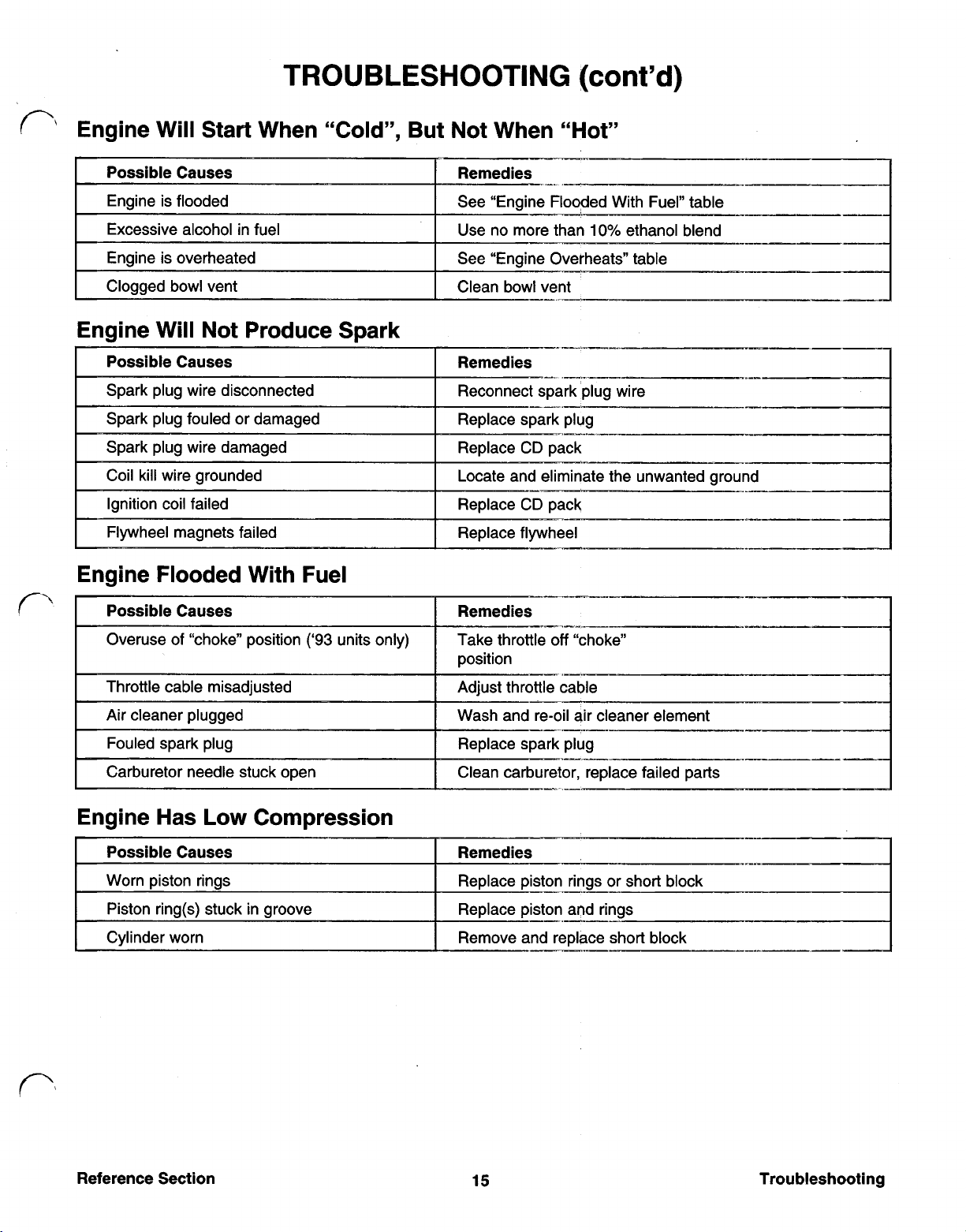
Engine Will Start When “Cold”, But Not When “Hot”
e Flooded With Fuel” table
Engine Will Not Produce Spark
Possible Causes
I
Coil kill wire grounded
Locate and eliminate the unwanted ground
(cont’d)
---~--
Engine Flooded With Fuel
I
Possible Causes Remedies
Overuse of “choke” position
Throttle cable misadjusted Adjust throttle cable
Air cleaner plugged
Fouled spark plug
Carburetor needle stuck open Clean carburetor, replace failed parts
Engine Has
Possible Causes
Worn piston rings
Low
Compression
(‘93
units only)
off
Take throttle
position
Wash and re-oil air cleaner element
Replace spark plug
Remedies
Replace piston rings or short block
Replace piston and rings Piston ring(s) stuck in groove
Remove and replace short block Cylinder worn
“choke”
-_-.-
I
I
Reference Section
15
Troubleshooting
Page 15
Engine Surges
TROUBLESHOOTING
‘(cont’d)
Possible Causes
Fouled idle circuit
Air leak
Restricted fuel flow
(‘93
models only)
Engine Backfires
Possible Causes Remedies
I
Flywheel key sheared
Muffler filled with carbon
Exhaust ports plugged
Engine Overheats
Possible Causes
Cylinder head cooling fins clogged
Restricted main carburetor jet
Improper gas to oil mixture
Cooling air intake plugged
Remedies
Clean idle circuit
Check sealing surfaces, oil seals, gaskets, and
Check filters and fuel line
Replace key
Clean muffler
Clean ports
Remedies
Clean fins thoroughly
Clean carburetor’ and jet
Ensure mixture is
Remove foreign material and clean
32:l
Engine Vibrates Excessively
Possible Causes
Blade out of balance
Bent blade Replace blade
Loose engine mounting screws
Bent crankshaft
Flywheel out
Troubleshooting
of
balance
Remedies
Balance blade or replace
Tighten engine mounting screws
Replace crankshaft
Replace flywheel
16
-.--_-
if
damaged
Reference Section
Page 16
TROUBLESHOOTING
(cont’d)
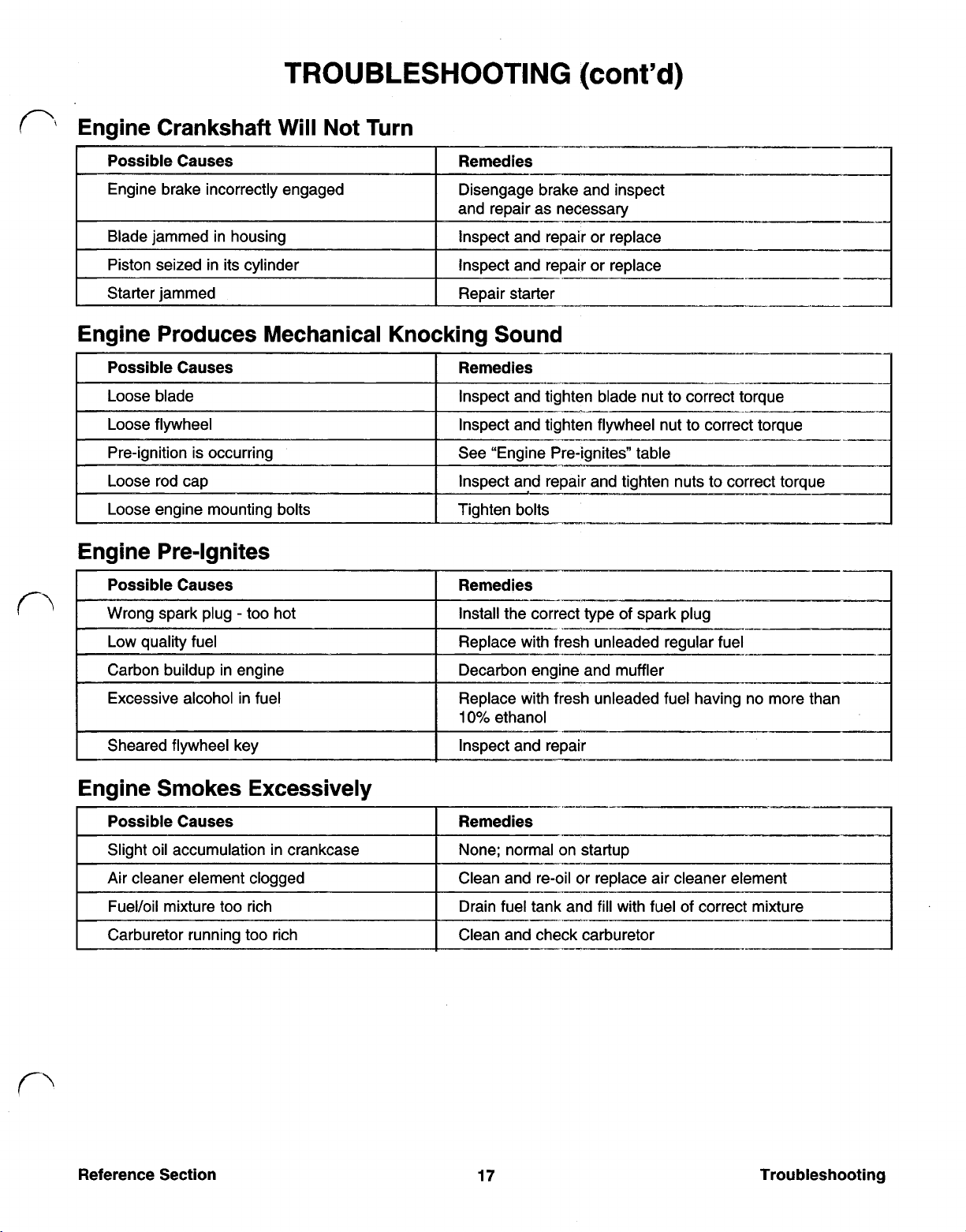
Engine Crankshaft Will
Possible Causes Remedies
Engine brake incorrectly engaged
Blade jammed in housing
Piston seized in its cylinder
Starter jammed
Not
Turn
Disengage brake and inspect
and repair as necessary
Inspect and repair or replace
Inspect and repair or replace
Repair starter
Engine Produces Mechanical Knocking Sound
Possible Causes Remedies
Engine Pre-Ignites
Possible Causes Remedies
Wrong spark plug too hot Install the correct type of spark plug
I
I
Replace with fresh unleaded regular fuel
Excessive alcohol in fuel
Sheared flywheel key Inspect and repair
Decarbon engine and muffler
Replace with fresh unleaded fuel having no more than
10%
_I-..
ethanol
Engine Smokes Excessively
Possible Causes Remedies
Slight oil accumulation in crankcase
Fuel/Oil mixture too rich Drain fuel tank and fill with fuel of correct mixture
Carburetor running too rich
None; normal on startup
Clean and re-oil or replace air cleaner element Air cleaner element clogged
Clean and check carburetor
_-
I
I
I
Reference Section
17
Troubleshooting
Page 17
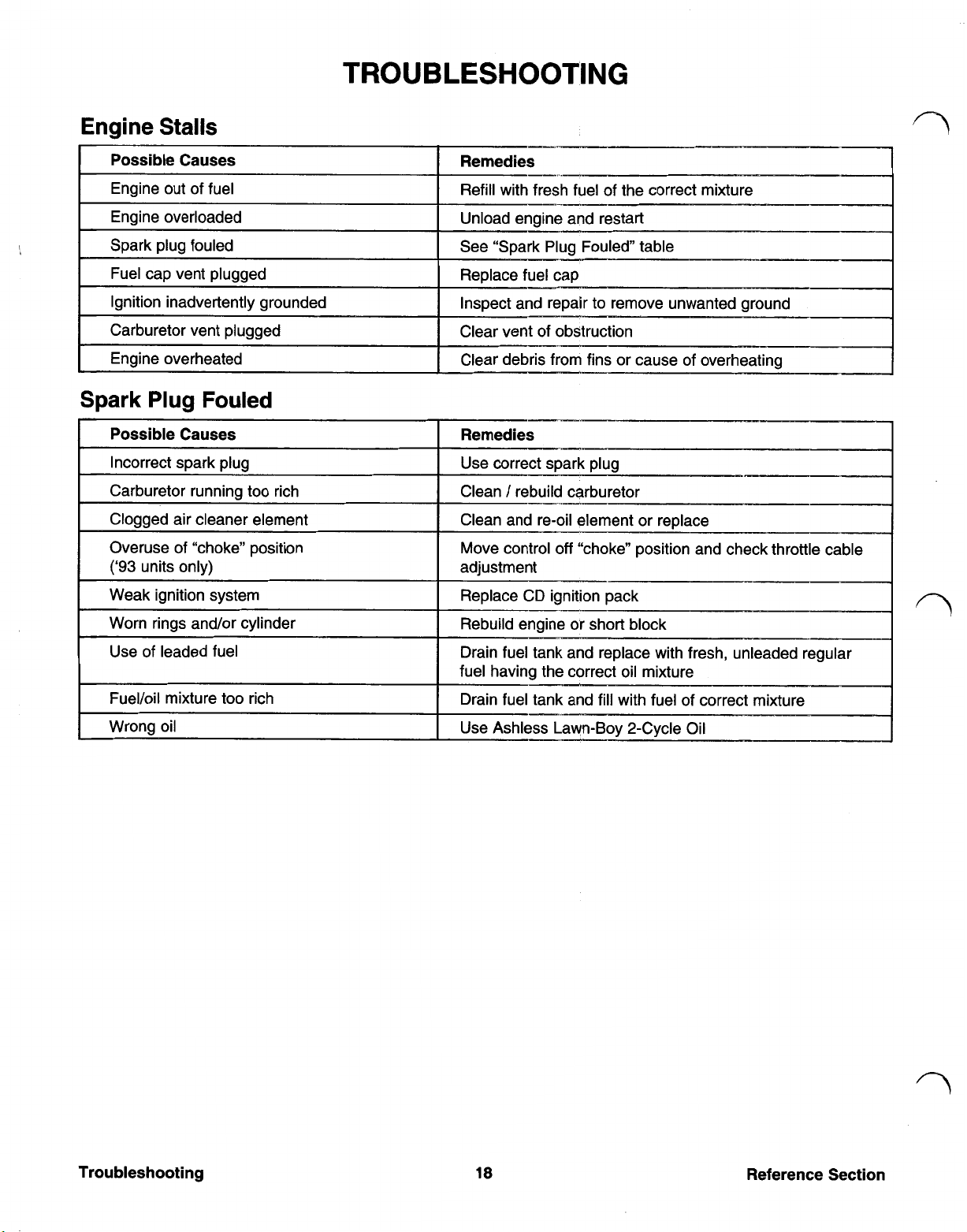
Engine
Stalls
Spark
Use
Plug
of
leaded fuel resh, unleaded regular
Fouled
Page 18

Recommeded Maintenance Schedule
25
50
100
Hours Air Filter
Hours
Hours
Blade Brake
I
Exhaust Ports
I
I
Cooling System
Check blade and engine mounting
f
bolts and screws tight to ensure safe operation.
replace.
Check for leakage and/or deterioration
Air
Filter
Once every season, or every
filter housing and element.
25
hours, clean the air
Do
so
more frequently
under dusty conditions.
Notes:
in place. Doing
Do not operate the engine without the air filter
so
may damage the engine or cause
excessive engine wear.
Figure 1 shows the
‘93
carburetor;
‘94
models have
an additional wire clamp to release.
1.
To remove air filter, snap cover latch open,
swing to side and unhook. Remove the cover
and air filter
(Figure
1).
Filter
Cover
Figure
1
Reference Section
19
Maintenance
Page 19

MAINTENANCE
(cont’d)
Air Filter
2.
3.
(cont’d)
Wash air filter in laundry detergent.
Squeeze filter to remove excess liquid and blot
dry with a paper towel or rag
Figure
Apply one tablespoon of SAE
filter
(Figure
distributed evenly throughout filter. Blot lightly
with paper towel to remove excess oil.
3).
Lightly squeeze filter until oil is
2
(Figure
30
oil to the air
2).
Spark
A spark plug that is dirty, pitted, carbon covered or
has worn electrodes may cause hard starting and
poor operation.
Clean or replace spark plug once a season or every
25 hours, whichever occurs first. Use Champion
RJ12C,
Remove spark plug and clean with a wire brush,
removing carbon buildup. DO NOT SANDBLAST.
Check condition of plug for cracks, damaged or worn
electrodes. Replace
1.
Plug
or
equivalent.
if
necessary.
Set spark plug gap at
See
Figure
,035
(.85
4.
in.
mm)
0.035
inch (.85mm).
Replace filter with cleanest side facing
carburetor.
Note:
is not puckered (allowing direct passage of air and dir
to carburetor).
Be sure filter is properly seated in air box and
Figure
3
Figure
2. Install spark plug finger tight, then torque to
ft
180 in Ibs (15
Ibs)
Figure
4
(20 N-m_
5
Figure
5.
Maintenance
20
Reference Section
Page 20

MAINTENANCE
Cleaning The Exhaust System
Warning:
accidentally starting the engine.
1.
I
Disconnect the spark plug wire to prevent
Using a 1/2 drive with a 15/16 socket, remove
the blade nut that secures both the mulch fan
and blade to the engine. Use heavy duty gloves
to hold the blade while removing the nut
(Figure
6).
Figure
6
(cont'd)
4.
Remove the three bolts to remove the muffler
cover. Drop the cover down to inspect the
condition of the exhaust ports, etc.
(Figure
5.
Pull the starter rope until the piston covers the
exhaust ports
a
3/8”
8).
(Figure
(9
mm) wooden dowel.
9).
Clean them with
2.
Using a soft hammer, gently tap the blade drive
it
to remove
(Figure
3.
If
necessary, clean the small louvers in the
muffler cover; they must be open.
from the shaft of the engine
7).
Figure
7
Ports
Figure 9
Reassembling Exhaust System
1. Insert three bolts into the muffler cover and
90
tighten to a torque of 150-1
7-22
(1
2.
Re-install the blade drive, beveled edge towards
the engine to match its shaft angle.
3.
Re-install the blade and mulch fan with the
15/16" nut. Be sure the small circular bosses on
the blade drive collar match the holes in the
(Figure
N-m)
blade. Tighten the nut to 50
6).
in Ibs
ft
Ibs
(68
N-m)
Reference Section
21
Maintenance
Page 21

SECTION
1
WALBRO
LMR-16
CARBURETOR
LMR-16 Carburetor Identification
The LMR-16 carburetor can be identified by its
aluminum body. Walbro (the manufacturer's name) is
also stamped on the side of the body. These
carburetor's were used on 1993 models.
LMR-16 Carburetor Theory of Operation
As
the crankshaft rotates, the piston moves back and
forth in the cylinder, alternately creating a pressure or
a partial vacuum in the crankcase
When a vacuum is created by upward piston
movement, the reed valve opens and air rushes
through the carburetor throat. The carburetor throat is
a venturi tube (large at each end but with a smaller
center passage). When the air rushes through this
tube, air pressure at the center of the passage
lowered.
(Figure
10).
is
LMR-16 Carburetor Governor Theory
The shaft of the governor air vane is attached to the
throttle disc of the carburetor
by the rotating flywheel, attempts to close the throttle.
The governor spring resists this force and attempts to
open the throttle. The balance between these two
forces is the governed engine speed. Spring tension
may be changed via an adjustable collar which
50
75
produces a
each adjustment "click"
RPM
so
that air flow, created
change in engine speed for
(Figure
12).
Figure
By inserting a tube from the carburetor float bowl into
the venturi
venturi draws fuel through the tube. The fuel/oil mix is
then picked up by, and mixed with, the moving air.
This fuel/oil/air mixture enters the crankcase through
the reed valves
operation of the engine as long as fuel is supplied
to it.
(Figure
(Figure
11).
10
lower air pressure at the
10)
thereby sustaining
Figure
12
Service Section
Venturi
Effect
Figure
11
25
Carburetor
Page 22

LMR-16
1.
2.
3.
4.
5.
6.
Carburetor Removal
Disconnect spark plug wire.
Remove Fuel Tank (See page 38).
Open and remove air cleaner cover and air filter
element.
Detach carburetor from engine by removing
mounting bolts. Remove and discard the
small carburetor gaskets. Save the carburetor
heat shield.
Disconnect the fuel line.
Pull the carburetor assembly down and away
from the engine such that the air vane clears the
hole in the shroud base
(Figure 13).
two
two
7.
Remove the throttle cable screw and nut and
disconnect the cable from the control lever
(Figure 14).
Figure 14
Figure 13
CAUTION:
damage to the governor spring.
8. Hold the carburetor in one hand and
cleaner box
choke shaft. Rotate the carburetor
counterclockwise and remove the spring from
the control lever.
Be careful in the next step to prevent
so
that the control lever clears the
lift
the air
Page 23

LMR-16 Carburetor Disassembly
.l.
Remove the in-line filter from the fuel inlet.
2.
Remove the screw holding the air vane to the
throttle shaft. Remove the air vane collar and
governor spring and remove the throttle valve
screw, plate and shaft
(Figure 15).
Figure 15
Remove the idle adjustment needle and spring.
Remove the bowl retaining bolt and gasket, the
bowl and the bowl gasket.
Remove the float shaft, float and inlet needle.
Remove the fuel inlet (Viton) seat using a short
piece of wire or a shot of compressed air.
Using an awl, pierce the Welch plug, then
so
carefully remove it
holes are exposed
that the idle progression
(Figure 17).
3.
Gently bend spread the slot in the choke shaft
and remove the choke plate using pliers. Lift
the choke shaft and spring from the carburetor
(Figure 16).
Figure 16
Figure 17
LMR-16 Carburetor Cleaning and
Inspection
Thoroughly clean all the carburetor parts and inspect
them for wear. Wash the jets and passages and blow
dry with compressed air immediately.
CAUTION:
in the carburetor.
Note:
sealer, use a spray cleaner to clean external surfaces.
Immersing the entire carburetor in a cleaning solution
will remove the seal coating.
Never enlarge or restrict any passageway
Since this carburetor has a special external
Service Section
27
Carburetor
Page 24

LMR-16
1.
2.
Carburetor Assembly
Install Welch plug using a blunt tool having the
same diameter as the Welch plug.
Install the fuel inlet valve seat: coat the seat with
oil and install it grooved side down
(Figure 18).
INSTALL
5.
Place bowl onto the carburetor body and install
the bowl retaining bolt and gasket
(Figure 20).
n
Figure 18
3.
Place the inlet needle on the float and install it
on
carburetor. Push the float pin into the
carburetor body through the float hinge
(Figure 19).
Note:
The float is not adjustable
necessary to check float height. However,
always make sure that no liquid is inside the float
before reinstalling.
so
it is not
Figure
Install idle needle and spring. Turn in until the
needle seats lightly then back it out
a turn.
Install the choke shaft and spring as shown
(Figure 21).
Figure 21
Make sure the opening on the choke plate
8.
faces left.
20
5/8
3/4
of
Figure 19
4.
Position the bowl gasket on the top edge of the
carburetor body.
Carburetor
28
Push the choke plate into the shaft
9.
Figure 22
(Figure 22)
CHOKE
Service Section
Page 25

LMR-16 Carburetor Assembly (cont’d)
10. Place a drop of Loctite on the screw and install
the throttle shaft and valve with the valve hole to
the left
(Figure 23).
LMR-16 Carburetor Presetting the
Governor
1. Hold the carburetor with the mounting flange
facing you and the throttle wide open.
2.
Preset the governor by turning the collar
3-4
the window on the collar is
of the pulse hole.
clicks to the right
so
that
Figure 23
1 1. Place the governor spring into the collar and
place the collar and spring onto the throttle shaft.
so
Position the collar
that the window is in line
LMR-16 Carburetor Assembling Air
to Carburetor
1. Hook the end
control lever and move the air box
counterclockwise.
2. Lift the control lever over the choke shaft and
place on the front
the post on the lever activates the choke.
3.
Install the carburetor mounting bolts
of
the governor spring into the
of the carburetor. Make sure
?
Figure 26
(Figure 26).
Box
4.
Place one carburetor-to-crankcase gasket onto
the carburetor for mounting bolts.
Figure 24
with the pulse hole
12. Install the air vane and screw
Service Section 29 Carburetor
(Figure 24).
Figure 25
AIR
VANE
(Figure 25).
5.
Install the heat shield as shown
Figure
(Figure 27).
27
Page 26

LMR-16 Carburetor Assembly (cont’d)
LMR-16 Carburetory Choke Adjustment
6. Install the remaining carburetor gasket; make
sure all pulse holes are aligned.
7.
Hook the control cable into the control lever and
fasten the cable to the air box.
LMR-16 Carburetor Installation
1.
While holding the carburetor and parts together,
turn the assembly and guide the air vane into the
opening in the shroud base
2. Install the bolts finger tight.
3. Pull the carburetor to the left and push the air
box to the right. Tighten the bolts and torque to
45
55
in Ibs (5.1 6.2 N-m)
4.
Check that the choke moves freely.
5.
Install a cleaned and re-oiled element into the air
box and install the air box cover.
(Figure
13).
LMR-16 Carburetor Final Check
The ‘93 Lawn-Boy LMR carburetor used in the
V
Engine has an all metal housing with a mechanical
choke, an adjustable idle mixture, a fixed main jet and
a fixed float.
1. Move throttle control to “choke” position.
2. Look into the carburetor and be sure the choke
is closed. Tighten the hex screw and nut on the
black plastic cable holder to keep the cable in
place.
3.
Install the in-line fuel filter and attach the fuel line
to the carburetor fitting.
LMR-16 Carburetor Servicing the Air Filter
To remove the air filter, at the left side, snap the
cover latch open, swing it to the right and
unhook it. Remove the cover and air filter
element
(Figure
28).
Perform the following preliminary checks to eliminate
some of the possibilities that may contribute to
carburetor malfunction:
Ignition system ensure that all components
1.
are adjusted to specs and are the correct
components.
Fuel tank and in-line filters must not be
2.
plugged.
Fuel cap vent hole must not be plugged.
3.
Air filter must be clean and oiled.
4.
Crankcase seal Crankcase seals must be
5.
installed properly and in good condition;
torque value on the bolts must be correct.
Carburetor flange gaskets and heat shield
6.
must be installed correctly (pulse holes must
be aligned).
Exhaust ports must not be restricted.
7.
Fuel mixture must be new and not of
8.
unknown quantities, not old, etc.
Governor air vane must move freely.
9.
Figure
28
Clean and re-oil the air filter element according
to the procedure in Maintenance, pages 19
20.
and
CAUTION:
element or with a dry element; engine life will be
shortened.
Do not operate the engine without a filter
Page 27

Engine Starts Hard
LMR-16 CARBURETOR-TROUBLESHOOTING
Engine Runs
Dirty air cleaner
I
Dirt in carburetor Clean carburetor
Engine Runs Lean
Carburetor bolts not tight Tighten bolts to 45 55 in Ibs (5.1
Improper carburetor
adjustment
I
Dirt in idle mixture pocket Remove Welch plug and clean
Restricted filter(s)
Welch plug leaking
Engine Surges
Rich
I
Clean
or
replace air filter element
Adjust to 5/8 to 3/4 turn open
Clean filter(s)
Seal all Welch plugs
6.2
N-m)
I
I
Fuel Leaks From Carburetor
Dirt under inlet needle
Bowl vent plugged Remove bowl and clean with compressed air
Float leaking (heavy) Replace float
Float stuck
(gummed carburetor)
Service Section
carburetor and crankcase
Remove inlet needle, clean or replace seat
Remove bowl and clean carburetor
31
I
I
Carburetor
Page 28

SECTION
2
PRIMER START CARBURETOR
Primer Start Carburetor Identification
The primer start carburetor is easily identified by its
primer and its black plastic body. It is different from
earlier Lawn-Boy plastic body carburetors because it
does not have the adjustable needle behind the air-
1994
vane governor. This carburetor is found on
newer V-Engines.
and
Primer Start Carburetor Theory
of Operation
As
the crankshaft rotates, the piston in a vertically
mounted engine moves back and forth in cylinder,
alternately creating a pressure or a partial vacuum in
the crankcase (Figure
When a vacuum is created by upward piston
movement, the reed valve opens and air rushes
through the carburetor throat. The carburetor throat is
a venturi tube (large at each end but with a smaller
center passage). When air rushes through this tube,
air pressure at the center of the passage is lowered.
29).
By inserting a tube from the carburetor float bowl into
30),
the venturi (Figure
venturi draws fuel through the tube. The fuel/oil mix is
then picked up by, and mixed with, the moving air.
This fuel/oil/air mixture enters the crankcase through
the reed valves,(Figure
operation of the engine as long as fuel is supplied to
it.
I
lower air pressure at the
29)
thereby sustaining
Venturi
Effect
Figure
30
Primer Start Carburetor Governor Theory
The shaft of the governor air vane is attached to the
throttle disc of the carburetor
by the rotating flywheel, attempts to close the throttle.
The governor spring resists this force and attempts to
open the throttle. The balance between these two
forces is the governed engine speed. Spring tension
may be changed via an adjustable collar which
50
75
produces a
each adjustment "click" it is moved
RPM
so
that air flow, created
change in engine speed for
(see
Figure
31).
1
Figure
29
-ADJUSTABLE
I
Figure
31
Page 29

Primer Start Carburetor Removal
1.
Disconnect spark plug wire.
2.
Remove fuel line and drain; remove the fuel tank
(see page 38).
3. Open and remove air cleaner cover and air filter
element. Remove the
covering the mounting screws.
4.
Detach carburetor from engine by removing two
mounting screws. Discard the
carburetor gaskets on either side of the
carburetor shield. Keep the heat shield for later
installation.
5.
Disconnect the fuel line and the primer tube from
the carburetor fittings
two
plastic plugs
two
(Figure 32).
smaller
6.
Pull the carburetor assembly down and away
from the engine such that the air vane governor
clears the hole in the shroud mounting base.
7.
Remove the throttle cable screw and nut from
the throttle cable mounting bracket.
CAUTION:
Be careful in the next step to avoid
damage to the delicate governor spring.
8. Slide the white plastic control lever to either end
it
of its adjustment and snap
to the locked
position to help restrict its movement while you
disconnect the throttle cable from the control
(Figure 34).
lever
CONTROL LEVER
Figure 32
Figure 34
Service Section 33 Carburetor
Page 30

Primer Start Carburetor Dissassembly
1.
At the throat of the carburetor, using a needle
nose pliers, gently pull the throttle plate out of
the air vane assembly shaft
the orientation of the small protrusions on the
throttle plate as you pull it out. The single
protrusion should be on your left; next to the hole
9
at the
o’clock position).
(Figure
35).
Notice
5.
Remove the fuel filter from the fuel nozzle.
6. Remove the float hinge pin, the inlet valve
needle assembly (with its clip) and the float
(Figure
7. Inspect the float for cracks or deterioration of the
cork.
8.
Remove the brass inlet fuel valve seat and
discard it
9.
Remove the nozzle and the high speed jet from
the nozzle.
36).
Discard the needle and clip.
(Figure
36).
Primer Start Carburetor Cleaning and
1. With the carburetor completely disassembled,
thoroughly clean all parts in a parts cleaning
solution and inspect for wear or deterioration.
Blow dry all carburetor passages with
compressed air. Use a spray cleaner only to
clean external surfaces.
Figure
3. Hold the governor collar on the carburetor and
lift the air vane/throttle shaft out of the
carburetor. Lift the collar and spring up,
detaching the spring from the speed control
lever.
4.
Turn the carburetor over and remove
the four bowl retaining screws, the
bowl gasket and the bowl
Discard the bowl gasket.
Gasket
Fuel
(main jet)
35
(Figure
fuel
36).
CAUTION:
restrict any passageway in the carburetor.
2.
Always check the carburetor mounting flange
and the fuel bowl mounting flange to be sure
they are flush.
If
tag wire
is
used, never enlarge or
Primer Start Carburetor Assembly
1.
Install the high speed jet into the fuel nozzle
(Figure
2.
Turn the carburetor over and install the nozzle
assembly into the carburetor body.
3.
Install a new brass inlet fuel valve seat.
4.
Install a new inlet valve needle and clip on the
float.
Install the float assembly with a new float hinge
5.
pin in the bottom of the carburetor. Ensure that
the hinge pin is positioned properly to keep the
float level. The float should be free to move up
and down easily in the carburetor body.
6.
Adjust float
flange (gasket not in place) to top of float.
36).
so
height is 7/16 to 15/32 from bowl
Carburetor
Figure
36
34
7.
Install the fuel filter over the fuel nozzle.
Service Section
Page 31

Primer Start Carburetor Assembly (cont’d)
8.
Install a new fuel bowl gasket and the fuel bowl
with the four bowl retaining screws.
9. Hook the governor spring into the bottom of the
governor collar.
10. Holding the spring in the collar, hook the other
end of the spring into the speed control arm.
Place the collar and spring over the carburetor
fitting.
11. Install the air vane and throttle shaft into the
carburetor body by very carefully pushing the
shaft through the collar into the carburetor body.
12. Push the throttle plate into the throttle shaft.
(Figure 37)
(The plate only inserts one way).
Primer Start Carburetor Installation
Install new gaskets and the heat shield (removed
1.
in a previous procedure) on the carburetor. The
air cleaner element and its cover should not be
in place at this time.
Guide the air vane through the opening in the
2.
shroud base from the bottom of the base and
attach the carburetor to the engine with
mounting screws. Tighten them to a torque of
45-55 in Ibs (5.1 6.2 N-m) Replace the cap
plugs.
Insert the bent wire
3.
vertical tab of the speed control lever. Set the
throttle to fast and the speed control lever
the throttle plate
4.
Install the fuel line and primer tube on the
appropriate carburetor fittings.
Check that the choke/air vane assembly
5.
moves freely.
Install the air filter element and cover.
6.
of
the throttle cable into the
is
sprung to the full open position.
two
so
that
Primer Start Carburetor Presetting the
Governor
Note:
approximately 50-75 RPMs.
Each “click” of the governor collar represents
1.
Turn the collar clockwise to increase spring
tension (and engine RPMs) or counterclockwise
to decrease spring tension and RPMs
(Figure 37).
4
clicks clockwise.
2. Use a tachometer to check engine speed;
normal setting is 3050 150 RPM.
Preset the governor collar 3 or
Figure 37
Primer Start Carburetor Final Check
The Primer Start carburetor used in V Engines has
an all Minlon housing with a fixed high speed jet and
an adjustable float.
Perform the following preliminary checks to eliminate
some of the possibilities that may contribute to
carburetor malfunction:
Ignition system
1.
are adjusted to specs and are the correct
components.
Fuel tank filter
2.
Fuel cap vent
3.
4.
Air filter
Crankcase seal
5.
installed properly and in good condition; torque
value on the bolts must be correct.
Carburetor flange gaskets and heat shield
6.
must be installed correctly.
must be clean and oiled.
ensure that all components
must not be plugged.
hole must not be plugged.
Crankcase seals must be
Exhaust ports
7.
Fuel
8.
9.
Service Section 35 Carburetor
mixture must be new, not unknown, etc.
Governor air vane
must not be restricted.
must move freely.
Page 32

Primer Start Carburetor Servicing the
Air Filter
1.
To remove the air filter, at the left side unsnap
the wire holder from the cover, and then unsnap
the cover from the clear plastic shell. Remove
the cover and air filter element
2. Clean and re-oil the air filter element according
to the procedure in Maintenance, pages
and 20.
(Figure
38).
19
CAUTION:
filter element or with a dry element; engine life
will be shortened.
Do
not operate the engine without a
PRIMER START CARBURETOR TROUBLESHOOTING
Engine Starts Hard
r replace as necessary
air cleaner element and carburetor
Tighten bolts to
--
realign gaskets and tighten
45
55
~I___-._
in Ibs
Figure
(5.1
38
6.2 N-m)
Engine Runs Lean
Fuel Leaks From Carburetor
5
55
Ibs
(5.1
6.2 N-m)
bowl and clean with compressed
Remove bowl and clean carburetor
Page 33

FUEL SYSTEM
Fuel System Operation
The V Engine uses a 1.5 quart plastic fuel tank
(Figure
filter screen. The filter is chemically welded in the
bottom
tank is mounted above the level of the carburetor and
uses gravity to supply fuel through a
mm) rubber hose to the carburetor. The fuel hose is
friction-fitted to the tank outlet at one end and to the
carburetor at the other end.
The fuel tank is vented through an opening in the fuel
cap. The fuel opening on the tank is
diameter and is opposite the fuel outlet, helping to
prevent damage to the filter screen by funnels and
gasoline filler spouts that may be inserted into the fuel
tank during refueling. The placement of the cap also
prevents interference with the starting rope in Zone
Start applications.
39) with a non-replaceable
of
the tank over a sediment reservoir. The
Figure
39
75
micron in-tank
.25”
I.D.
1.75”
(45
(6.35
mm)
Fuel System Cap Service
1.
The fuel cap may not be disassembled; however,
the vent opening on the cap and inner sealing
disc should be kept free of debris.
2.
The ventilating ability of the cap may be tested
by filling the cap with water and observing the
flow of water out of the vent opening in the top of
If
the cap.
opening may be plugged or restricted.
3.
If the fuel cap will not vent properly, replace the
entire cap assembly.
water does not drain, the vent
Figure
40
The fuel cap is a four piece design
an inner sealing disc that is vented to a baffle
assembly in the body of the cap. The baffle assembly
allows expansion in the tank without the
Atmospheric pressure is allowed into the tank from an
opening in the cap to allow gravity to feed fuel to the
(If
carburetor.
entire assembly must be replaced.)
Service Section
an individual part of the cap fails, the
(Figure
loss
40)
of fuel.
with
37
Fuel System
Page 34

Fuel System Tank Removal
1.
Disassemble the starter rope
(Figure 41)
starter rope knot and release the rope. (The
plastic rope stop prevents the rope from
rewinding completing into the starter).
Note:
crimp the fuel hose and use a forceps to remove
the fuel hose from the carburetor
sufficiently to untie (or cut) the
Figure 41
To remove the fuel tank, you may either
OR
You may reach under the edge of the fuel tank
to pull the hose off the tank outlet, but
be ready to catch the fuel that will drain out of
the tank.
If
you use this method, you must have a
container large enough to hold the amount of
fuel in the tank.
CAUTION:
in a container designed for gasoline and
Avoid fire and explosion. Store fuel
smoke while working around gasoline.
Release the clamping pliers and drain the fuel
into a container designed to receive gasoline.
If
2.
you removed the fuel line from the tank outlet,
catch the fuel as it drains out of the tank outlet.
Set the fuel aside and away from the immediate
working area.
“T”
handle
you
never
must
3.
Using
a
#
T25 TORX driver, remove the three
screws with captive washers and spacers that
secure the fuel tank to the shroud assembly
(Figure 42)
Figure 42
Fuel System Cleaning
1.
Take the fuel tank to an appropriate area and
wash the tank in clean solvent intended for
cleaning engine parts.
2. Back wash the filter screen by directing cleaning
solvent, under moderate pressure, through the
sediment reservoir and screen, opposite the
direction of fuel flow.
3.
Wash the tank again with clean solvent.
4.
Clean or replace the fuel hose.
Fuel System Tank Installation
1.
Fasten the tank to the engine with the three
screws with captive washers and spacers.
2.
Connect the fuel line.
Page 35

SECTION
4
Ignition System Troubleshooting
Check the ignition system in the following order:
Spark plug (connection & wire, condition)
CD Pack (air gap, connections or spark)
Flywheel (key and magnets)
Use the following table to aid in diagnosing the
problem.
IGNITION SYSTEM
Problem
Misfiring, no firing,
engine surges, engine dies
(Note: these symptoms
may also be caused by
fuel symptom problems).
Possible Cause
Spark plug or lead wire loose
Spark plug in poor condition
CD Pack air gap wrong
CD Pack high tension lead loose
CD Pack leads loose or dirty
CD Pack defective
Flywheel key damaged or sheared
Flywheel magnets demagnetized
or weak
Ignition System Spark Plug Operation
The spark plug ignites the oil-fuel mixture by
producing a spark just before the piston reaches top
dead center (TDC). A spark plug is typically
constructed as shown in
Figure
43.
Suggested Remedy
Tighten plug to specifications
Adjust (see CD Pack - Service in this section).
Secure with
Replace flywheel.
GE
silicon sealant.
I
Ignition System Spark Plug Service
1.
Check spark plug with chart in this subsection
and replace, following specifications given on
this page.
CAUTION:
2.
Clean with a wire brush, removing the carbon
buildup. Check conditions of the plug for
cracking or damage. Replace as necessary.
Service Section
Do not clean plug with a sand blaster.
Gap at
.89
mm
(.35")
39
Figure 43
Ignition System
Page 36

Ignition System
CD
Pack
Operation
The V Engine uses a solid state ignition module to
generate an electrical pulse for the spark plug. The
term “solid state” is a broad term applied to any
electrical system which uses electronic components
such as diodes, transistors, silicon controlled rectifiers,
etc., that take the place of one or more of the older
standard mechanical ignition components.
Electronic components are very small, have no
moving parts, require no mechanical adjustments, and
are not affected by wear as are mechanical devices.
They deliver uniform performance throughout
component life under adverse operating conditions,
so
can be hermetically sealed
that they are unaffected
by dust, dirt, oil or moisture.
is
The Capacitive Discharge (CD) system
breakerless,
and contains electronic components that replace
mechanical points and related accessories (such as a
breaker cam, spark advance assembly, etc).
Figure 44
the
V
shows the location of the CD Pack used in
Engine.
When the SCR
is
triggered or “fires”, up to
200
volts
DC, stored in the capacitor, travels to the spark coil.
Here it is stepped up to as much as
25,000
volts and
is discharged across the electrodes of the spark plug
(Figure 46).
SPARK PLUG
Figure 46
At slower speeds, the flywheel magnet induces a
smaller charge in the trigger coil. This action triggers
the silicon controlled rectifier (SCR) enabling easier
5
starting in a “retarded firing position” about
before top dead center (BTDC)
(Figure 47).
degrees
Figure 44
As the flywheel magnet passes the CD Pack, an AC
voltage is induced into the charge coil. This AC
voltage is converted by a rectifier into a DC signal
which is then stored in a capacitor
(Figure 45).
POLE SHOE.
LEG
LEG
SHOE
Figure 47
At
At faster speeds (about
800
RPM),
the flywheel
magnets induce a large enough charge in the trigger
coil to trigger the SCR in the “advanced firing position’’
25
(about
degrees BTDC)
(Figure 48).
Ignition System
Figure 45
40
CRANKSHAFT
25.”
BTDC
AT
Figure 48
Service Section
Page 37

Ignition System CD Pack
Air
Gap Adjustment
1.
Rotate flywheel until the magnets are directly
adjacent to the CD Pack as shown in
Figure 49
2.
Adjust gap by loosening screws, inserting Lawn
Boy gauge (p/n 604659) or a piece of
stock and tightening screws.
Figure 49.
.010
shim
Ignition System Flywheel Operation
The flywheel is connected directly to the Crankshaft
(secured by a flywheel key and nut) and turns at the
same speed as the crankshaft. Two permanent
magnets, imbedded in the flywheel, rotate past the coil
in the CD Pack to begin the generation of electricity.
Imbedded in the opposite side of the flywheel are
steel counterweights which offset the weight of the
magnets. These counterweights are not magnetic.
Ignition System Flywheel Removal
1.
Remove spark plug and install piston stop
(p/n,677389)
(Figure 51).
Ignition System CD Pack
Removal/Installation
1.
Disconnect leads and remove mounting screws.
2.
Remove screws, replace CD Pack and set gap
1
as outlined in step
100
torque of
in. Ibs
above. Tighten screws to a
(1 1
N-m)
(Figure
Figure 50
Figure 51
50).
Service Section 41 Ignition System
Page 38

2. Remove shroud and fuel hoses.
3. Remove flywheel nut.
4. Remove flywheel by pulling up on edge of
flywheel while striking wide fin of flywheel with
a soft hammer
(Figure 52).
Figure 52
4. Torque flywheel nut
Ibs (43 47 N-m)
(Figure 54)
Figure 54
to 375-425 in
5. Remove key and check its condition.
6.
Replace crankshaft and/or flywheel
distorted or cracked.
7.
Check flywheel for wear and flywheel magnets
for strength.
if
keyway is
Ignition System Flywheel Installation
1.
Make sure flywheel keyway is absolutely clean.
2.
Make sure key is installed correctly
3. Locate keyway cutout in flywheel over key
and shaft.
MAKE
SURE
IS
INSTALLED
CORRECTLY
KEY
(Figure
53).
RIGHT WRONG
Ignition System
Figure
53
42 Service Section
Page 39

SECTION
5
REWIND
Rewind Starter Operation
The rewind starter operates through a retainer/friction
two
disc that causes
the center of the rewind starter and engage the inside
of the starter hub on the flywheel. The engagement
dogs move into contact with the starter hub when the
rewind rope is pulled. When the engine starts, the
speed of the engine exceeds the speed of the rewind
starter and forces the starter dogs back into the center
of the rewind mechanism, disengaging them from the
starter hub.
engagement dogs to extend from
Rewind Starter Removal and
Disassembly
Note:
to the shroud.
1.
2.
The rewind starter assembly housing is riveted
Remove the fuel tank.
Remove the four screws that secure the shroud
to the shroud base
front screw is a
5/16
are
3/8
hex.
(Figure 55).
hex while the other three
Note that the
STARTER
Figure 56
5.
Remove the
springs Take note of the positioning of the
springs for correct installation later.
(Figure 56).
6.
Completely extend the rewind rope of the starter
and hold the reel in place. Untie the knot in the
end of the rope, withdraw the rope and slowly
allow the reel to unwind to a relaxed state.
two
starter engagement dogs and
Figure 55
3.
To service and/or replace the starter
engagement dogs and springs, turn the shroud
over to gain access to the starter mechanism.
4.
Use a
No.
1
Phillips screwdriver to remove the
Phillips-head shoulder screw from the center of
the rewind mechanism and lift the retainer plate
from the starter.
7.
Remove the reel from the rewind housing. The
is
rewind spring
fall out or be released suddenly
careful The rewind spring is not serviceable.
the spring has failed, an entirely new spring and
reel assembly must be used for repair.
captured in the reel and will not
if
you are
If
Service Section
43
Rewind Starter
Page 40

Rewind Starter Reassembly
1.
Lubricate the center post
with a small amount
2.
Place the reel assembly on the center post of the
rewind starter and turn the reel counterclockwise
until the hook on the reel spring engages the
spring retainer on the center post
(Figure
57).
of
the rewind starter
of
general purpose grease.
of
the starter.
4.
Install the retaining plate and Phillips shoulder
screw. Tighten the screw to a torque
(3.7 N-m)
(Figure
59).
of
33 in Ibs
Figure
3. Install the engagement dog springs and the
center spring as shown in
57
Figure
58.
Figure
CAUTION:
performing procedures of the next step.
5.
Pretension the spring by turning the pulley
plate counterclockwise
through the guide, then the reel.
6.
Tie a single knot in the end
singe the end with a lighter to prevent the
knotted end of the rope from fraying
Figure
Wear gloves for protection while
60).
59
5
turns. Insert the rope
of
the rope; then
(see
Figure
58
44
Figure
60
Service Section
Page 41
Rewind Starter Reassembly (cont'd)
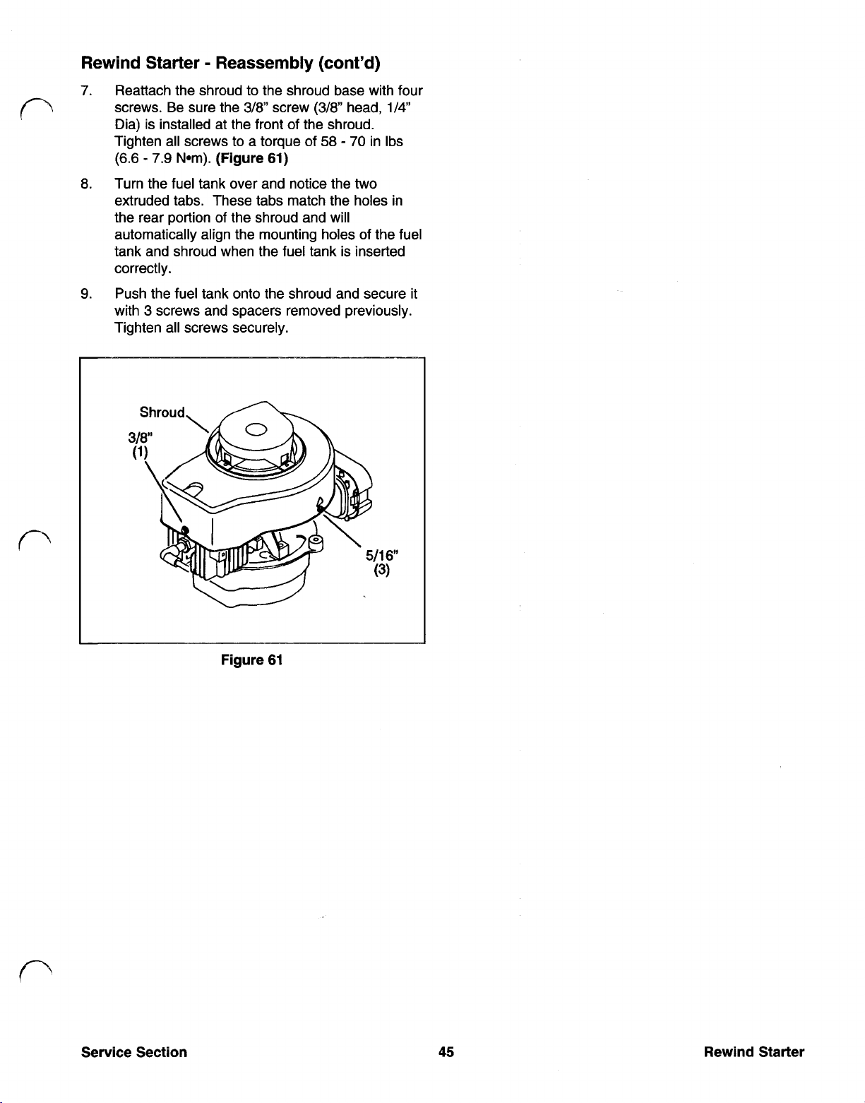
7. Reattach the shroud to the shroud base with four
3/8
screw
(3/8”
58
head,
70
in Ibs
two
screws. Be sure the
Dia) is installed at the front of the shroud.
Tighten all screws to a torque
(6.6 7.9 N-m)
8.
Turn the fuel tank over and notice the
extruded tabs. These tabs match the holes in
the rear portion of the shroud and will
automatically align the mounting holes of the fuel
tank and shroud when the fuel tank is inserted
correctly.
9. Push the fuel tank onto the shroud and secure it
3
with
Tighten all screws securely.
screws and spacers removed previously.
Shroud,
(Figure 61)
of
1/4"
Figure 61
Service Section
45
Rewind Starter
Page 42

SECTION
6
ENGINE
Engine Description
Two-cycle engines have special advantages which
make their use more practical in certain applications.
Two cycle engines are lightweight with an excellent
power-to-weight ratio and can be operated in any
position. They are also notably easy
service because of their uncomplicated design. The
V
Lawn-Boy Two-cycle
rotary motors is a reed valve design. This design
name describes the path of the fuel/air mixture into
the cylinder/crankcase and combustion chamber, and
the exhausting of spent gases.
Engine Theory
Two two-cycle (or two-stroke) engine is one of the
simplest and most efficient power systems ever
developed.
Figures 62 and 63
the engine during one full crankshaft revolution. Fuel
intake, fuel ignition and the exhaust of burned gases
all take place during a single 360-degree rotation of
the crankshaft.
Reed
Engine used on Lawn-Boy
of
Operation
below show what happens inside
to maintain and
first stroke
The movement of the piston towards the spark plug
also has an important effect in the crankcase. Once
the transfer port is sealed, the crankcase is under
vacuum. This action pulls the reed valve open and
draws in a fresh charge of air/fuel mixture.
Just before the piston reaches top dead center (TDC),
the spark plug fires. When the engine is functioning
properly, the air/fuel mixture ignites, causing a burn
that occurs evenly through the power stroke.
compression ratio is too high, the air/fuel mixture
actually explodes, which can be heard and is
identified as detonation). The burn continues as the
piston changes direction and begins its travel towards
the crankcase.
When the piston opens the exhaust port, high-
pressure exhaust gases exit the exhaust port. Further
movement of the piston towards the crankcase
uncovers the transfer port which allows a fresh charge
of oil/fuel mixture to enter the combustion chamber.
As
the exhaust gases continue to exit the exhaust port
the engine is readied for another cycle.
The 2-cycle engine
the correct oil/fuel mixture is maintained in the fuel
tank. Oil suspended in the fuel vapor adheres to all
moving parts, keeping them continually coated,
I
regardless of operating angle.
second (or power) stroke
is
always well lubricated as long a
Figure 63
of
a 2-cycle engine.
(If
the
illustrates the
I
Figure 62
Beginning at a point where the top of the piston is just
below the exhaust port, the piston moves forward
As
toward the crankcase.
uncovered, the air/fuel mixture stored in the
pressurized crankcase is forced into the combustion
chamber.
The crankshaft continues its rotation and the piston
begins its travel toward the spark plug.
the piston seals off the transfer port first, then the
exhaust port. When both ports are sealed, the
remaining travel compresses the air/fuel mixture to
prepare it for ignition. The travel of piston towards the
spark plug is called the compression stroke
(Figure 62).
the transfer port is
As
it moves,
Figure 63
Second
Stroke
Engine
46
Service Section
Page 43

Engine Service Tips
The numbers in parentheses in the discussions that
A.
follow refer to the exploded views in Appendix
major items are:
Cylinder/Crankcase Halves (21, page A-2).
1.
two
The
be mixed. Check cleaning and assembly N-m)
procedures under Engine Disassembly in this
subsection. Be sure to use Loctite 515 on the
mating surfaces. Torque the four washer-head
screws that secure the
in Ibs (12 13 N-m)
halves are a matched pair and cannot tightened to a torque of
two
halves to 105 11
The
5
7.
Carburetor Gaskets (24, page A-4).
Carburetor gaskets (24) on either side of the
carburetor shield (1) may be leaking or damaged
causing air leaks into the engine (may cause
power fluctuations). Ensure that air
cleaner/carburetor mounting screws
45
55
in Ibs
(6)
(5.0
are
6.1
Engine Removal
Prior to disassembling the engine and prior to further
troubleshooting a malfunction, separate it from the
mower as follows:
Oil Seals (3, page A-2).
2.
leaky or damaged oil seals
Core Plugs
3.
damaged or leaky plugs (four locations). will keep the rope from rewinding completely into
Muffler Baffle
4.
be cleaned every
carbon from clogging exhaust system
power
piston scoring).
5.
Muffler Plate Screws (2, page A-3).
may have loosened due to vibration. They
should be tightened to a torque of 140 200 in
(16
Ibs
6.
Exhaust ports
as necessary
(1
page A-2).
(1
50
loss)
and from entering engine (causing
22 N-m)
should be inspected and cleaned
(Figure 64).
Visually inspect for 1. Disconnect the spark plug wire.
(two
locations).
Visually inspect for knot in the starter rope. (The plastic rope stop
page A-3).
hours (maximum) to keep 3. Remove the fuel tank (page 38).
This item should
Screws
2. Disassemble the
4.
5.
6.
'T
starter handle to untie the
the starter).
Remove the shroud (page 43); starter comes
off
with shroud.
Remove the flywheel (page 41).
Remove the remaining bolts securing the shroud
base to the crankshaft halves
(Figure 65).
Ports
I I
Figure 64
Service Section 47 Engine
Figure 65
Page 44

Engine
5.
Removal
Remove brake plate assembly by removing one
10
mm shoulder screw and one 3/8 washer-
head screw. Place the assembly on the mower
deck and disconnect the ground wire (that goes
to the CD Pack).
(cont’d)
(Figure 66).
9. On self-propelled models only, remove the 5/16
screw to remove the belt drive cover. Remove
3/8”
two
drive guide bracket to the drive unit
67
(belt will stay with the engine as cover is
removed).
screws with spacers that secure the belt
(Figures
&
68).
Remove the drive belt from the pulley
Figure 66
7.
Remove the CD Pack (page 41).
Note:
carburetors have an additional wire holder that
must be released to remove the air cleaner
element. Mounting screws are identical.
8.
Snap open the air cleaner cover (catch on left,
hinge on right) and remove the air filter element.
Remove the
to the engine. Disconnect the fuel line from the
carburetor. Separate the carburetor from the
engine with controls attached and set it on the
mower deck.
Step 8 covers ‘93 carburetors; ‘94
two
screws securing the carburetor
Figure 67
Page 45

Engine Removal (cont’d)
10.
Remove the spark plug and install piston stop
(p/n 677389) in the spark plug hole.
1 1. Remove the 15/16 blade nut that secures the
blade and mulch fan to the engine shaft. Use
heavy duty gloves to hold the blade while
removing the nut.
2.
Remove the entire crankshaft assembly and
discard the oil seals (3, page A-2).
3. Carefully remove the
screws
rod cap and the split bearing liner. The needle
roller bearings are under the split bearing liner
(Figure 70).
(9,
page A-2) to remove the connecting
HSH
(hex, sockethead) cap
Notes:
material in the blade nut, use a new nut after the
fourth time it has been removed and re-installed.
Since the engine shaft and blade collar protrude
beyond the bottom of the muffler cover, have a
couple of short lengths (about 1
set about four inches apart to set the engine
after removing
12. Under the mower deck, remove the three 1/2”
bolts that secure the engine to the mower deck
and
the deck and set it on the 2 x
arrangement).
Due to the nature of the self-locking
ft
ea) of 2 x 4‘s
it
in the next step.
lift
the engine (with drive belt) up and out
4‘s
(or equivalent
on
of
Engine Disassembly
Note:
engine disassembly in the following paragraphs, the
engine exploded view is shown on page A-2.
Numbers used in the text refer to that view.
1. Remove the four crankcase cap screws with a
In addition to the figures supplementing the
E-12
Torx No.
using a screwdriver
socket and separate the halves
(Figure
69).
Figure 70
Remove the piston and rod assembly; separate
if
the assembly
pliers (p/n 303857) on the retaining ring (16).
Use wrist pin knock out tool (p/n 602884) to
punch out wrist pin (17).
necessary, using a compression
(Figure 71).
Figure 71
Figure
Service Section
69
49
Engine
Page 46

Engine Inspection and Repair
Engine Reed Valve Service
Check bearings for wear and freedom of
if
movement: replace
Check rings for sticking, remove and check rings
for wear or damage; replace rings
questionable.
Check all parts for wear or damage and replace
if
questionable.
Clean crankcase surfaces with Gel Seal and
Gasket Remover
questionable.
if
(Figure 72).
These assemblies
enter the crankcase
trap fuel mixtures in the crankcase on power strokes.
1.
Check clearance between tip
replace reeds
(.4 mm).
CAUTION:
reeds.
(Figure 73)
on
compression strokes and to
Figure 73
if
clearance is more than
Do not use compressed air to clean
permit fuel mixtures to
of
reed and plate;
.015
Figure 72
5.
Check that the ring end gap is between
.016
with
.030
and
6. Replace core plugs (1)
Lock (p/n 682301) on outside surfaces and
special tool (p/n 609904) for installation.
CAUTION:
with a drill bit. An enlarged hole will reduce
compression and engine efficiency.
Do
as the wear limit.
if
leaking, using Screw
not attempt to clean any hole
.006
2.
Clean reeds carefully, by hand, using carburetor
solvent.
3.
When replacing reeds, install smooth edge down
(Figure 74)
of
screws.
and use Loctite 271 on threads
Figure 74
Page 47

Engine Reassembly
1. Secure wrist pin using snap ring. Make sure
square edge of snap ring faces out and ring
opening faces up (toward top of piston)
(Figure
75).
SNAP
RING
6. Oil parts and use piston stop (p/n 677389) and
ring’compressor (p/n 609967) to install piston
with “BTM” mark facing down toward exhaust
ports
Note:
(Figure
77).
Letters “BTM” were omitted on some
engines. However, the small “rectangle” should
still be visible through ports.
Figure
75
2. Install pressure back piston ring in top groove
with bevel facing up; stagger ring gaps.
CAUTION:
Use piston stop to prevent top ring
from falling into cylinder and causing damage.
3. Assemble rod cap. Ensure that dovetail ends of
liners are matched. Install new needles
p/n 68391 1.
Note:
One side of the paper is sticky; remove
paper carefully while installing needle bearings.
There should be 32 needle bearings on the
lower connecting rod.
4.
Lubricate and assemble bearings (lettered side
out) to Crankshaft and install crankshaft.
5.
Install rod cap; ensure that mating marks are
aligned. Clean old screws thoroughly and apply
Loctite 271
(Figure
76).
Torque to 70 in-lbs
(7.8 N-m)
7. Apply Loctite
51
5
Figure
77
gasket maker very thinly to
the crankcase cover sealing surface, being
careful not
(Figure
to get sealant on bearings or seals
78).
Figure
78
ALIGNMENT
Service Section
MARKS
Figure
76
51
Engine
Page 48

8.
Carefully align the
two
crankcase halves using
the alignment pin and its matching hole; press
two
the
halves together
(Figure
79).
Reinstalling External Components
10. Reattach the flywheel brake system.
11. Install new
oil
seals.
12. Install shroud base.
13. Clean crankshaft and flywheel hub and install
flywheel (see page 42).
Figure
9.
Tighten the hex washer head screws to a total of
110 in Ibs (12.5 N-m)
(2.26 N-m) increments
that the crankshaft turns freely
79
tightening only20 in lbs
at
a
time
while checking
(Figure
INCREMENTS
80).
14. Install
carburetor
and governor assembly (see
page 30 for '93 models, page 35 for '94 models).
15. Install starter and shroud assembly and starter
handle (see page 45).
16. Reconnect fuel lines and electrical system leads.
17. Test run engine.
Engine
Figure
80
52
Service Section
Page 49

Introduction
In 1982 the federal government mandated that all
25”
consumer walk behind mowers with a cut of
cm) or less be equipped with safety devices. There
are two primary criteria which these devices must
meet:
1.
A
two-step operation must be performed in order
to start the blade rotating.
2. The blade must come to a stop within three
seconds of the operator leaving the operator’s
position.
One of the ways the Lawn Boy Corporation met these
requirements was with the “zone start system.” This
system utilizes a kill switch and a brake which stops
the engine when the operator releases the blade
control bail
engagement criteria is met by requiring the operator to
pull the bail to the handle first, then pull the recoil rope
from the operator’s position.
(Figure 81).
The two-step blade
(63.5
The switch is closed when the blade control bail is in
the “at rest” (vertical) position
the bail to the main mower handle opens the switch.
Switch leads are connected to the primary side of the
coil and to ground. When the switch is closed, the
electronic ignition module is bypassed
cannot interrupt primary current flow. This action
prevents the coil from producing the high voltage
necessary to generate spark. When the switch is
open, the ignition coil produces spark.
Stopping the engine and blade is accomplished by
means of a brake that is applied to the bottom of the
flywheel. The brake spring is in the “braked position
when the blade control bail is in the “at rest” or vertical
position. When the blade control bail is lowered to the
mower handle the brake is retracted from the under
side of the flywheel to allow the engine to run.
(Figure 81).
so
that it
Lowering
Pivoting Zone Start Brake Disassembly
See
Figure 82;
disassembly continued next page.
43
Figure 81
Pivoting Zone Start Brake Operation
The pivoting style zone brake system has two main
functions. The first function of the system is to stop
the production of spark and the second is to stop the
engine and the blade.
Stopping spark production is controlled by a switch.
Service Section
53
Figure 82
1
Ground strap stop
2 Self-tapping screw
3
Brake switch lead wire
4
Ground strap
5
Insulation strap
6 Plastic rivet (self expanding) (2)
7
Shoulder screw (10 mm)
8 Brake plate assembly
9 Screw
10 Brake mounting plate
Pivoting Zone Start Brake
Page 50

Pivoting Zone Start Brake Disassembly
(cont'd)
Note:
procedures refer to Figure 82 on previous page.
1.
2. To reduce the pressure
3.
Numbers in parentheses in the following
If
the engine and blade are taking more than
seconds to stop when the blade control bail is
released
wear and replace
brake pad and the brake plate are replaceable
only as an assembly.
brake mounting plate (10) and brake plate (8),
squeeze tabs of brake cable that hold it in place
at the brake mounting plate. Push cable through
the hole in brake mounting plate.
Slide cable out through horizontal slot in brake
mounting plate. Also, slide the ball end of the
cable up through the vertical slot in the brake
plate.
,
inspect the brake pad for excessive
if
necessary. Note that the
of
the spring between
3
2. Secure the replacement brake plate to the
engine with shoulder screw (7). Tighten it to 90
in Ibs (9.2 N-m) Ensure that the brake plate
pivots freely.
3.
Slide the cable into the narrow slot on the brake
mounting plate and then push the cable into the
hole making sure the tabs lock into the bracket.
4.
One end
shape to
in the brake plate. Squeeze the compression
spring and slip it over the cable between the
brake mounting plate and brake plate.
5.
Insert the leaded ball end of the cable into the
vertical slot of the brake plate
of
the compression spring has a hook
it;
that end hooks over an indentation
(Figure 83).
Note:
head with
10 mm).
4.
Remove the 10 mm shoulder screw (7) to
remove the brake plate and brake pad attached
to it.
5.
If
requires replacement, remove the second screw
(9) to remove the brake mounting plate from
the engine.
In step
the ground strap or any part of this assembly
4,
some units may use a
1/4"
diameter screw (rather than a
3/8
Pivoting Zone Start Brake Assembly
1.
If
the brake mounting plate was not removed
from the engine, simply reconnect the grounding
lead to the push-on terminal directly above the
(4)
ground strap stop
reassembly process.
Note:
tighten screw (9) to 60 70 in Ibs (6.78 7.91
N-m)
If
the brake mounting plate was removed,
and continue with the
Figure 83
6. Operate the blade control bail to verify that the
(3)
brake mechanism stops within three
There is no adjustment needed after this
assembly process is completed.
seconds.
Page 51

This appendix contains an assortment
They are listed below as they appear on the following pages
Power Head Exploded View A-2
Ignition and Exhaust Exploded View A-3
Starter and Walbro LMR-16 Carburetor Exploded View A-4
Walbro LMR-16 Carburetor Assembly Exploded View A-5
Primer Start Carburetor Assembly Exploded View A-6
of
diagrams which may help you in the service and repair
of
this section
of
the V Engine
Service
Section
A-1
Appendix
Page 52

Power Head Exploded View
@-3
9
1 Core plug
2 Dowel
3 Oil Seal (2)
4
Needle bearing
5
Slotted head screw
6 Reed backup plate
7 Carburetor reed
8
Washer head hex screw
9
HSH
10 Split liner (2)
11 Needle Bearings
12
Upper main bearing
13 Crankshaft
Appendix
(4)
cap screw
(2)
(2)
(4)
Bearing
14
15
Connecting rod assembly
16
Retaining ring
17 Wrist pin
18 Piston
19 Piston ring
20 Top piston ring
21 Cylinder and crankcase assembly
22
Sealant (not illustrated)
A-2
Service Section
Page 53

Ignition and Exhaust Exploded View
1 Baffle
2 Screw
3
Muffler plate
4
Ground strap stop
5
Self-tapping screw
6
Brake switch leadwire
7
Ground strap
8 Insulation strap
9 Self-expanding plastic rivet
10 Shoulder screw
11 Brake plate assembly
12 Screw
13 Brake mounting plate
14 Hex washer-head screw
15
16
17 Exhaust gasket
18 Muffler cover
19 Screw
(4)
CD
ignition pack
Spark plug
(3)
-3
(2)
Service Section A-3 Appendix
Page 54

Starter and Walbro LMR-16 Carburetor Exploded
View
1 Carburetor heat shield
2 Gasket
3
Carburetor assembly
4 Air filter base
5 (not used)
6
Screw (2)
7 Air filter
8 Air filter cover
9 Retainer
10 Lever
11 Screw
12 Washer
13 Throttle spring
Appendix
14 Air vane collar
15 Air vane
16 Screw
17 Shroud assembly
18 Hex flange nut (4)
19 Nut
20 Starter hub
21 Flywheel assembly
22 Shroud base
23 Key
24 Carburetor gasket
25 Lockwasher
(3)
A-4 Service Section
Page 55

Walbro
LMR-16
Carburetor Exploded View
!
I
12
13
14
15
16
Ref Part
No. No.
1
2
3
4
5
6
7
8
9
10
11
12
13
14
15
1
Description
Valve inlet needle
Valve seat
Choke valve
Choke return spring
Idle needle spring
Welch plug
Idle needle
Choke shaft
Throttle shaft
Throttle valve
Throttle valve screw
Float
Float shaft
Bowl gasket
Fuel bowl
Bowl retainer gasket
Bowl screw
Quantity
1
1
1
1
1
2
1
1
1
1
1
1
1
1
1
1
1
Ref
No.
*
*
*
*
*
Part
No.
684286
684285
683783
682782
683778
683777
683781
Description Quantity
Throttle kit 1
9,
10,
11)
(Includes
Idle needle kit
(Includes
Float assembly kit
(Includes 12, 13, & Bowl kit)
Bowl kit
(Includes
Gasket kit 1
(Includes 14
Overhaul kit
(Includes 1, 2, 6, 13, & Gasket kit)
Choke kit 1
(Includes 3, 4,
&
5
&
7)
15,
17, & Gasket kit)
&
16)
&
8)
1
1
1
1
17
Service Section
*
=
Not illustrated
A-5 Appendix
Page 56

Primer Start Carburetor Assembly Exploded View
6
-Air vane
2 Retainer
3 Lever
4 Air vane collar
5 Throttle spring
6
Throttle plate
7 Cable bracket
8 Screw (2)
9
Air filter base
10 Inlet seat
11 Inlet needle
12 Retainer
9
10
11
12
21
17
18
19
13 Gasket
14 Main nozzle
15 Filter screen
16 Float
17 Float pin
18 Carburetor bowl
19 Screw (4)
20 Washer
21 Main jet
22 Air filter
23 Air filter cover
24 Air filter cover retainer
Service Section
 Loading...