

Page 1
FORM NO. 3318-781 REV A
Super Recycler®
Walk-behind Power Mower
Model No. 20461, 20462, 20463, 20472, 20473-- 6900001 & Up
Model No. 20467, 20468, 20469, 20470, 20478,
20479, 20480 -- 7900001 & Up
Super Recycler®
Tondeuse motoris_e &guidage arriere
Modele No. 20461, 20462, 20463,
20472, 20473 m 6900001 et suivants
ModUle No. 20467, 20468, 20469 20470, 20478,
20479, 20480 m 7900001 et suivants
Super Recycler ®
Cortadora de c_sped motorizada empujada por
el usuario
Modelos N. 20461, 20462, 20463,
20472, 20473 -- 6900001 y siguientes
Modelos N. 20467, 20468, 20469, 20470, 20478,
20479, 20480 m 7900001 y siguientes
Operator's Manual
Manuel de L'Utilisateur
Manual del Operador
Page 2
The engine exhaust from this product
contains chemicals known to the State of
California to cause cancer, birth defects,
or other reproductive harm.
Les gaz d'echappement du moteur de ce
produit contiennent des produits
chimiques reconnus dans I'_tat de
Californie comme canc_rig_nes,
responsables de malformations
congq_nitales, ou comme nocifs & I'_gard
des fonctions de la reproduction.
El escape del motor de esta herramienta
contiene productos quimicos que segdn
la informaci6n del Estado de California
producen cdncer, defectos congenitos u
otros riesgos reproductivos.
Page 3

Figures-- Figuras
\
1 1064
Self-propelled models
Modble autotract_
Modelo autopropulsado
English
1, Model and serial number decal
Fran_ais
1. D_calcomanie de num6ros de module et de s_rie
Espa_ol
1. Calcomanfa con los n6meros de modelo y serie
1778
Hand push models
ModUle non tract_
Modelo de empuje manual
English
1. Model and serial number decal
Fran_ais
1. Decalcomanie de num6ros de module et de s6r_e
EspaSol
1. Calcomania con los n_meros de modelo y serie
PrintedinUSA All Rights Reserved i
©The Toro Company - 1996, Rev. 1997
Page 4
Figures--Figuras
Fq
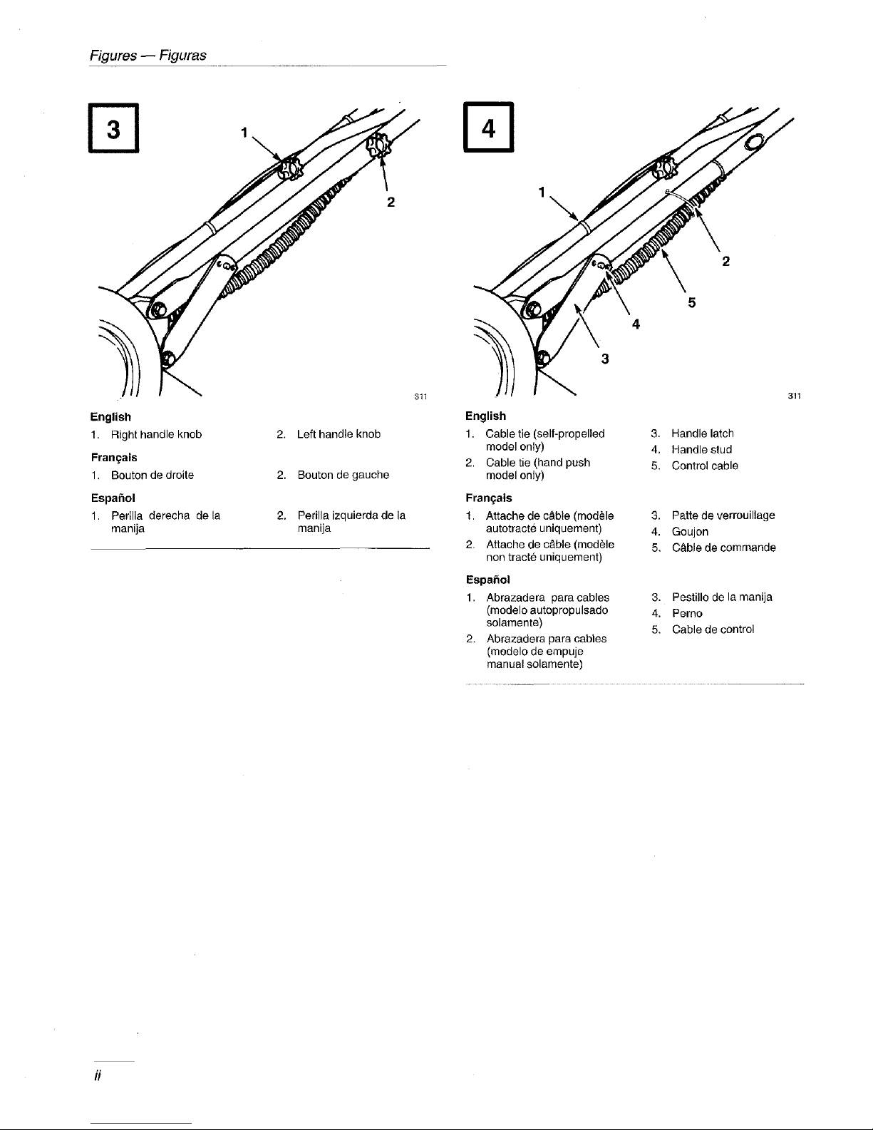
English
1. Right handle knob
Fran_ais
1. Bouton de droite
Espafiol
1. Perilla derecha de la
manija
2. Left handle knob
2. Bouton de gauche
2, Perilla izquierda de la
manija
311
rq
1
English
1. Cable tie (self-propelled
model only)
2, Cable tie (hand push
model only)
Fran_als
1. Attache de c&ble (modele
autotracte uniquement)
2. Attache de c&ble (modUle
non tract6 uniquement)
Espa_ol
1. Abrazadera paracables
(modelo autopropulsado
solamente)
2. Abrazadera para cables
(medelo de empuje
manual solamente)
4
3
311
3. Handle latch
4. Handle stud
5. Control cable
3. Pattede verrouillage
4. Goujon
5. C&ble decommande
3. Pestiilo de la manija
4. Perno
5. Cable de control
Page 5
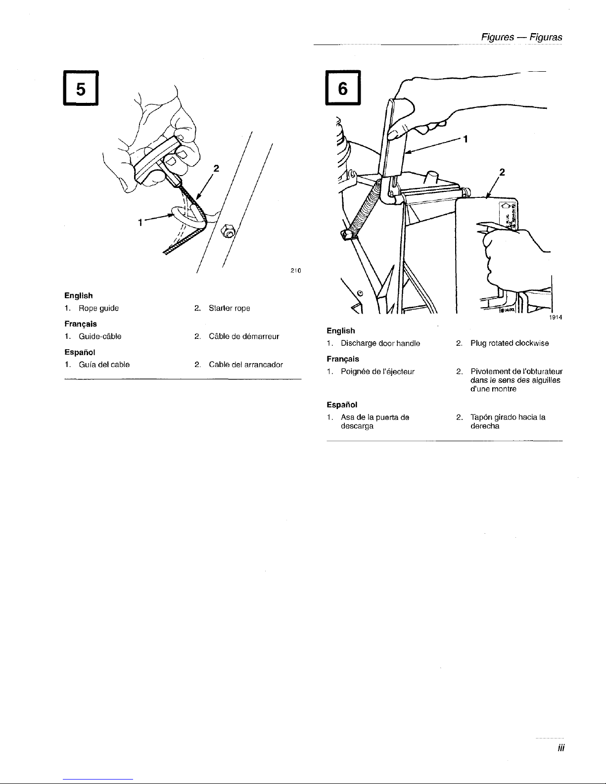
English
1. Rope guide
Fran_ais
1. Guide-c&ble
Espa_ol
1. Gufa del cable
2. Stader rope
2, C&ble ded6marreur
2. Cable del arrancador
210
English
1. Discharge door handle
Fran_ais
1. Poignee de I'_jecteur
Figul'es -- Figurss
2. Plug rotated clockwise
2. Pivolement del'obturateur
dane le sens des aiguilles
d'une montre
1914
EspaSol
1. Asa de la puerta de
descarga
2, Tap6n girado hacia la
derecha
Page 6
Figures -- Figuras
English
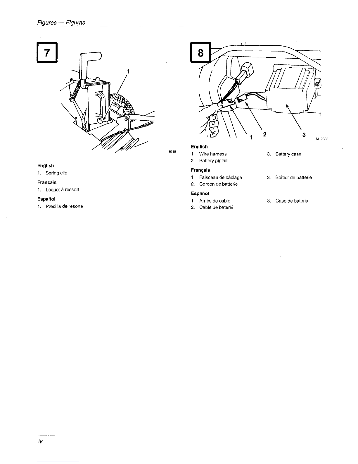
1. Spring clip
Fran_ais
1. Loquet _ ressort
EspaSol
1. Presilla de resorte
./_ _--" En0,,.. 2 °-2°°3
1915
1. Wire harness
2. Batte W pigtail
Fran_ais
1. Faisceau de c&blage
2. Cordon de batterie
Espahol
1. Arn6s de cable
2. Cable de bated&
3. Battery case
3. Boitier de batterie
3. Caso de bateria
iv
Page 7
4
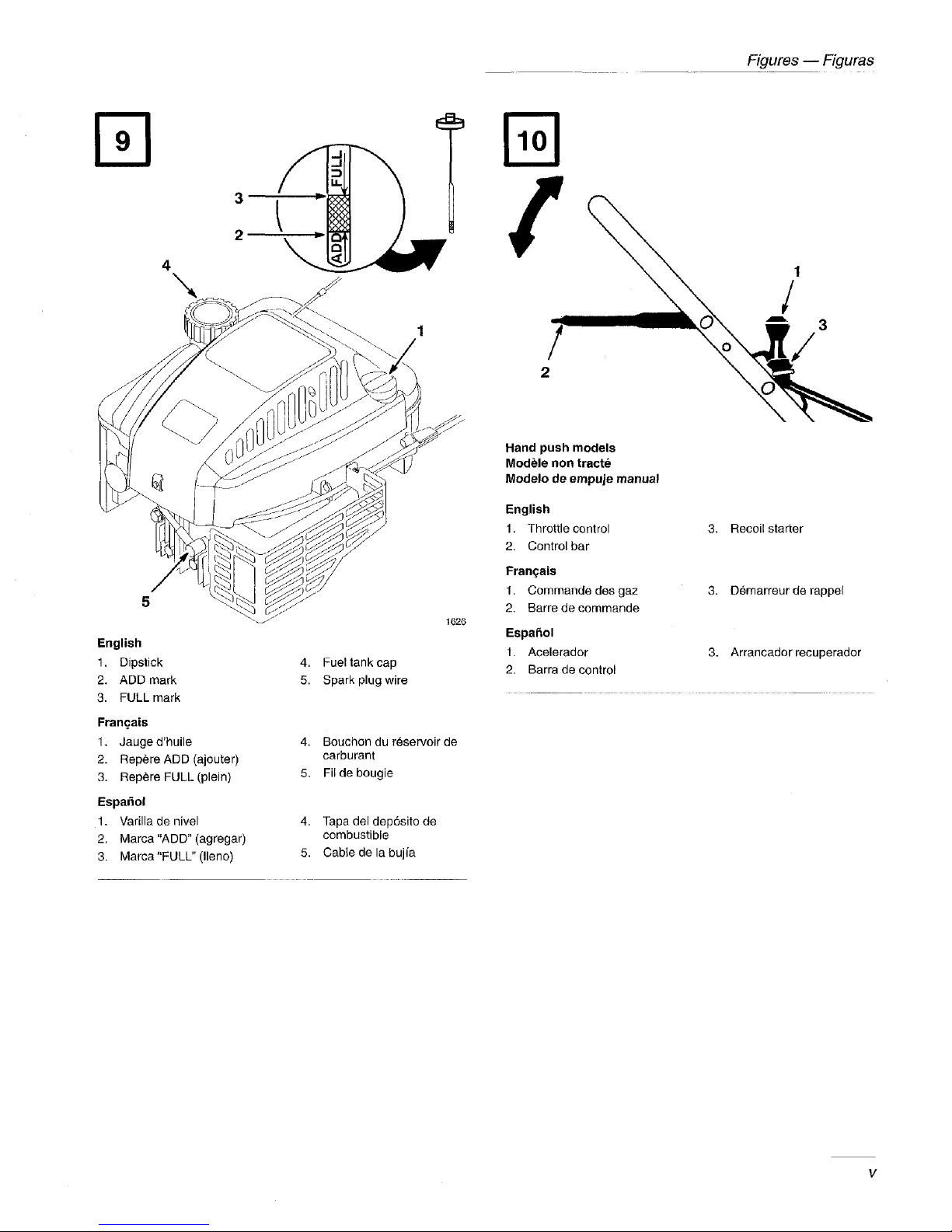
English
1. Dipstick
2. ADD mark
3. FULL mark
Figures -- Figuras
.J
IL
2
\
2
Hand push models
ModUle non tract6
Modelo de empuje manual
English
4. Fuel tank cap
5. Spark plug wire
1. Throttle control
2. Control bar
Fran_ais
1, Commandedes gaz
2. Barre de commande
1626
Espa£tol
1. Acelerador
2. Barra de control
3. Recoil starter
3. Demarreur de rappel
3. Arrancador recuperador
Fran_ais
1. Jauge d'huile
2. Repere ADD (ajouter)
3. Rep_re FULL (plein)
Espa_ol
1. Varilla de nivel
2. Marca "ADD" (agregar)
3. Marca "FULL" (lleno)
4. Bouchon du r_servoir de
carburant
5. Filde bougie
4. Tapa del dep6sito de
combustible
5. Cable de la buj_a
Page 8
Figures -- FJgurss
2
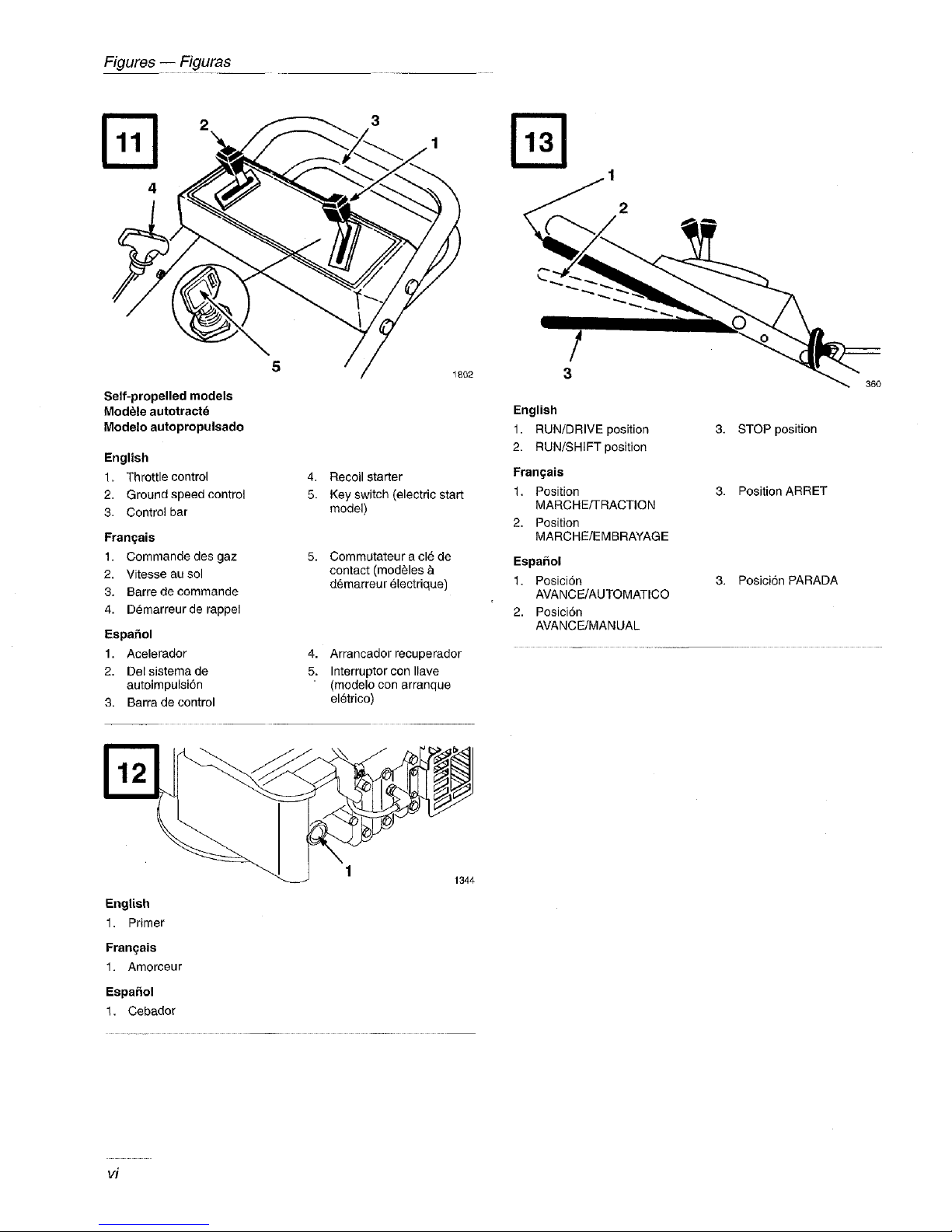
Self-propelled models
ModUle autotractd
Modelo autopropulsado
English
1. Throttle control
2. Ground speed control
3. Control bar
Fran£ais
1. Commande des gaz
2. Vitesse au sol
3. Barre de commande
4. Demarreur de rappel
Espafiol
1. Acelerador
2. Delsistemade
autoimpulsi6n
3. Barra de control
5
4. Recoil starter
5. Keyswitch (electric start
model)
5. Commutateur a cl6 de
contact (mod¢les &
d_marreur _lectrique)
4. Arrancador recuperador
5. Interruptor con Ilave
(modelo con arranque
el_trico)
Fq
/
3
English
1. RUN/DRIVE position
2. RUN/SHIFT position
Frangais
1, Position
MARCHE/TRACTION
2. Position
MARCHE/EMBRAYAGE
Espa_ol
1. Posici6n
AVANCE/AUTOMATICO
2. Posici6n
AVANCE/MANUAL
36O
3. STOP position
3. Position ARRET
3. Posici6n PARADA
English
1, Primer
Fran(;ais
1. Amorceur
Espa_ol
1, Cebador
vi
1
1344
Page 9

Fq
Figures-- Figuras
English
1. Bag frame on retaining
post
2. Pin engaged in catch
Fran£ais
1. Armature du sac
accroch6e au tenon
2. Ergot engag_ dans
I'encoche
Espa_ol
1. Marco del saco en el
poste retenedor
2. Pasador enganchadoen
el tanque
3. Handle fully forward.
Discharge door closed.
3. Poign6e _ fond vers
I'avant. Volet d'6jeclion
ferm&
3. Manija completamente
hacia adelante. Puerta de
descarga cerrada
1912
1913
English
1. Pin locked in bag notch
Fran£ais
t. Ergot bloqu_ dans I'encoche du sac
Espa_ol
1. Pasador trabado en la ranura del saco
Fq
778
Page 10
Figures -- Figuras
@
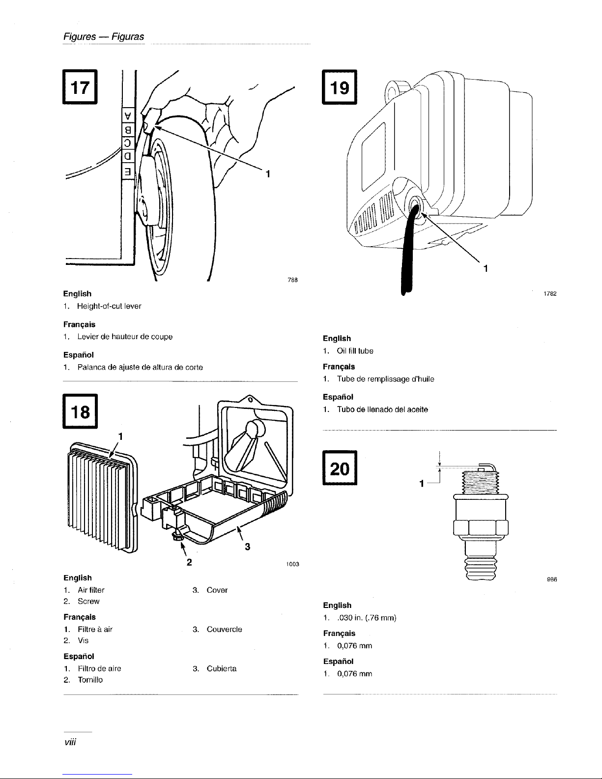
English
1. Height-of-cut lever
1
788
1782
Franqais
1. Levier de hauteur de coupe
EspaSol
1. Palanca de ajuste de altura de corte
2
English
1. Air filter
2. Screw
Fran(_ais
1. Filtre _.air
2. Vis
Espafiol
1, Filtro de aire
2. Tornilto
3. Cover
3. Couvercle
3. Cubierta
English
1. Oil fill tube
Fran(;ais
1. Tube de remplissage d'huile
EspaSol
1. Tubo de Ilenado del aceite
]
%
(
3
1003
986
English
1. .030 in. (,76 mm)
Franqais
1. 0,076 mm
EspaSol
1. 0,076 mm
viii
Page 11
Figures-- Figuras
p-q
English
1. Cover
Fran£ais
1. Capet
Espahol
1, Tapa
2. Screw (2)
2. Vis (2)
2. Tornillo (2)
2
1709
\
\
402
English
1. Control knob
Fran£ais
1. Bouton decommande
Espa_ol
1. Bot6n de mando
3 4
\
English
1. Cable clamp screw
2. Throttle cable
Fran£ais
1. Vis du serre-c&ble
2. C&ble des gaz
EspaRol
1. Tornille de la abrazadera
del cable
21 Cable del acelerador
3. Throttle lever
4. Throttle stop
3. Manette d'accel_rateur
4. Butee d'acc_lerateur
3. Palancadel regulador
4. Topedel regulador
English
1. Bolt and Iockwasher
2. Accelerator
Fran£ais
1. Boulon et rondelle de
blecage de la lame
Espahol
1. Pemo y arandela de la
cuchilla
3 757
3. Blade
2. Acc61erateur
3. Lame
2. Acelerador
3. Cuchilla
ix
Page 12
Figures-- Figuras
1
• ,,..,4
B O 2
F
3
C © 2
r_
English
1. Flat part of blade 3, Wear Fran£ais
2. Sail 4. Slot formed 1. Graisseur
Fran_ais EspaRol
1. Section plane dela lame 3. Usure 1. Engrasador
2. Pale 4. Fente formee ---
EspaRol
1. Parte plana de la cuchilla 3. Desgaste
2. Aleta 4. Ranura formada
1712 English
1. Grease fitting
Fq
J 153
/
1 276
English
1. Sharpen at this angle only
Fran£als
1. Aiguisez a cet angle seulement
Espa_ol
1. Afile en este angulo solament
Page 13
Self-propelled models
ModUle autotract_
Modelo autopropulsado
© Fq
777
Hand push models
ModUle non tract_
Modelo de empuje manual
Figures -- Figuras
1
\
4
5
251
English
1. Handle
2. Brake lever
3. 1/8"-3/16"
Fran£ais
1. Mancheron
2. Levier de frein
3. 3,2 4,8mm
Espahol
1. Manija
2. Palanca del freno
3. 3,2-4,8 mrn
4. Nut
5. Cable conduit
4. Ecrou
5. Gafne du c&ble
4. Tuerca
5. Conducto del cable
English
1. Handle 4. Nut
2. Broke lever 5. Cable conduit
3. 1/8"-3/16"
Fran_ais
1. Mancheron 4. Ecrou
2. Levier de frein 5. Gaine du cable
3. 3,2-4,8 mm
Espafiol
1. Manija 4. Tuerca
2. Palanca del freno 5. Conducto del cable
3. 3,2-4,8 mm
English
1. Kickers
Fran£ais
1. Plaques de d_flection
Espa£=ol
1. Placas deflectoras
1
796
xi
Page 14
Figures -- Figuras
English
1. Right rear wheel
Fran_ais
1. Roue arri_re droite
Espahol
1. Ruedatrasera derecha
1093
English
1. Discharge tunnel
Fran_ais
1. Conduit de rejecteur
Espa_ol
1. Canal de descarga
/12
1915
2. Discharge tunnel plug
2. Obturateur
2. Tap6n del canal de
descarga
English
1. Belt cover
Fran£ais
1. Garde de la courroie
EspaSol
1. Tapa de la correa
2. Bolt
2. Boulon
2, Tornillo
281
1
English
1. Side discharge chute
Fran_ais
1. Ejecteur lat6ral
EspaSol
1. Canaleta de descarga lateral
2047
Page 15
Contents
Storage ................................ 19
Fuel ............................... 19
Page
Introduction ............................ 1
Safety ................................. 2
Safe Operating Practices .............. 2
Safety and Instruction Decals .......... 4
Assembly .............................. 6
Handle ............................ 6
Starter Rope ........................ 6
Discharge Tunnel Plug ................ 6
Battery ............................ 6
Before Starting .......................... 7
Oil ................................ 7
Gasoline ........................... 7
Recycling Tips .......................... 8
General Tips ........................ 8
Operation .............................. 9
Controls ........................... 9
Starting Engine ...................... 9
Stopping Engine ..................... 9
Self-propelled Drive .................. l0
Pulling Mower Rearward .............. 10
Using Discharge Tunnel Plug .......... 10
Using Optional Grass Bag or Side Discharge
Chute ............................ 11
Adjusting Cutting Height .............. 12
Maintenance ............................ 13
Recommended Maintenance Schedule ... 13
Air Filter ........................... 14
Drain Gasoline ...................... 14
Change Engine Oil ................... 14
Spark Plug ......................... 15
Throttle Cable ...................... 15
Self-propelled Cable ................. 15
Blade ............................. 16
Lubrication ......................... 17
Blade Brake ........................ 17
Charging Battery .................... 17
Disposing of Battery ................. 18
Cleaning ........................... 18
Engine ............................ 20
Cleaning ........................... 20
General ............................ 20
Removing From Storage .............. 20
Accessories ............................ 20
The Toro Starting Guarantee ............... 22
Guaranteed To Start Maintenance Record ..... 24
Warranty ............................... 25
Introduction
Thank you for purchasing a Toro product.
All of us at Toro want you to be completely satisfied
with your new product, so feel free to contact your
local Authorized Service Dealer for help with service,
genuine Toro parts, or other information you may
require.
Whenever you contact your Authorized Service
Dealer or the factory, always know the model and
serial numbers of your product. These numbers will
help the Service Dealer or Service Representative
provide exact information about your specific
product. You will find the model and serial number
decal located in a unique place on the product
(Fig. 1 & 2).
For your convenience, write the product model and
serial numbers in the space below.
Model No.
Serial No.
Read this manual carefully to learn how to operate
and maintain your product correctly. Reading this
manual will help you and others avoid personal injury
and damage to the product. Although Toro designs,
produces and markets safe, state-of-the-art products,
EN-I
Page 16
you are responsible for using the product properly
and safely. You are also responsible for training
persons who you allow to use the product about safe
operation.
The Toro warning system in this manual identifies
potential hazards and has special safety messages that
help you and others avoid personal injury, even death.
DANGER, WARNING and CAUTION are signal
words used to identify the level of hazard, However,
regardless of the hazard, be extremely careful.
DANGER signals an extreme hazard that will cause
serious injury or death if the recommended
precautions are not followed.
Safe Operating Practices
This product is capable of amputating hands and feet
and throwing objects. Always follow all safety
instructions to avoid serious injury or death.
POTENTIAL HAZARD
• Engine exhaust contains carbon monoxide,
which is an odorless, deadly poison.
WHAT CAN HAPPEN
• Carbon monoxide can kill you and is 'also
known to the State of California to cause
birth defects.
WARNING signals a hazard that may cause serious
injury or death if the recommended precautions are
not followed.
CAUTION signals a hazard that may cause minor or
moderate injury if the recommended precautions are
not followed.
Two other words are also used to highlight
information. "Important" calls attention to special
mechanical information and "Note" emphasizes
general information worthy of special attention.
Safety
This machine meets or exceeds CPSC blade safety
requirements for walk-behind rotary mowers and
the B71.1 specifications of the American National
Standards Institute, in effect at time of
production. However, improper use or
maintenance by the operator or owner can result
in injury. To reduce the potential for injury,
comply with these safety instructions and always
pay attention to the safety alert _ symbol which
means CAUTION, WARNING or
DANGER--"personal safety instruction." Failure
to comply with the instruction may result in
personal injury.
HOW TO AVOID THE HAZARD
• Do not run engine indoors or in an enclosed
area.
This mower is designed for cutting and recycling
grass or, when equipped with a grass bag, for
catching cut grass. Any use for purposes other than
these could prove dangerous to user or bystanders.
Note:
This engine is NOT_equipped with a
spark arrester muffler. Use or operation
of this mower in the State of California
on any forest-covered, brush-covered
or unimproved grass-covered land,
without an approved spark arrester
muffler, is a violation of the law. Other
states may have similar laws.
General Operation
.
Read this manual carefully before operating the
mower. Become familiar with the controls and
proper use of the mower. Never allow children
under 16 years of age to operate the mower.
Never allow adults to operate mower without
proper instructions.
.
The operator of the mower is responsible for
keeping everyone, especially children and pets,
away from area of operation. The operator is
responsible for accidents or hazards occurring to
other people or their property.
EN-2
Page 17
.
Thoroughly inspect area where mower will be
used and remove sticks, stones, wire, and debris.
Watch for foreign objects while mowing.
t
Wear long pants and substantial shoes. Do not
operate mower while wearing open-toed shoes,
jewelry, loose clothing or when barefoot.
.
Check fuel level before starting engine. Because
fuel is highly flammable, handle it carefully.
A. Use an approved container.
B. Fill fuel tank outdoors, not indoors.
NEVER ADD FUEL TO AN ENGINE
THAT IS RUNNING OR HOT.
C. Install gas cap on fnel container and gas
tank, and wipe up any spilled gasoline
before starting engine.
D. Do not smoke while refueling.
Q
Keep all guards, shields, grass catchers and
safety devices in place. Repair or replace
damaged parts, including decals. Check all
safety devices before each use.
o
Before using, always visually inspect to see that
the blades, blade fasteners and cutter assembly
are not worn or damaged. Replace worn or
damaged blades and fasteners in sets to preserve
balance.
.
Traction drive (self-propelled model), blade and
engine are designed to stop when control bar is
released. Ensure control mid brake function
properly before each use of mower.
.
Disengage the self-propelled mechanism or drive
clutch (self-propelled model) before starting the
engine.
While Operating
.
Always maintain secure footing. Keep a finn
grip on the handle and walk; never run. Never
operate mower in wet grass. Mow only in
daylight or in good artificial light.
o
Mow across the face of slopes; never up and
down. Use extreme caution when changing
direction on slopes. Do not mow excessively
steep slopes. Wear skid resistant shoes on slopes.
Always wear safety glasses or eye shields during
operation to protect eyes from foreign objects
that may be thrown from the machine. Wearing
of hearing protection, protective gloves and a
safety helmet is advisable.
6.
Keep face, hands, and feet away from the mower
housing and cutter blade when the engine is
running. Blade can cause injury to hands and
feet. Stay behind the handle until the engine
stops.
f
Use extreme caution when reversing or pulling
the mower towards you.
8.
Since the blade rotates for a few seconds after
the control bar is released, stay behind the
handle until the engine stops.
.
When bagging grass, stop engine and stay
behind handle until all moving parts stop before
removing and emptying bag.
10.
When mowing, ensure grass bag is installed over
discharge opening.
11.
Shut engine off and stay behind handle until all
moving parts stop before unclogging chute.
12.
After striking a foreign object or if mower
vibrates abnormally, stop engine and remove
wire from spark plug. Check mower for damage
and make all repairs before using mower again.
If major repairs are ever needed or if assistance
is desired, contact your local Authorized Toro
Service Dealer.
1. Do not run engine indoors.
2. Start the engine carefully according to
instructions and with feet well away from the
blade.
13.
Stop the engine and wait for all moving parts to
stop before adjusting tile height-of cut.
14.
Stop the blade when pushing the mower outside
the lawn area.
EN-3
Page 18
15.
Stop engine before leaving the operator's
position - behind the handle. Disconnect wire
from spark plug if mower will be unattended.
16.
Do not touch engine while it is running or
shortly after it is stopped because engine will be
hot enough to cause a burn.
17.
Refuel only when engine is cool.
18.
If mower must be lifted to be transported, turn
off engine and stay behind the handle until all
moving parts stop.
Maintenance
.
Perform only those maintenance instructions
described in this manual, ff major repairs are
ever needed or if assistance is desired, contact
your local Authorized Toro Service Dealer.
,
Before mower is cleaned, inspected, serviced, or
adjusted, stop engine and disconnect wire from
spark plug. Keep wire away from plug to prevent
accidental starting.
.
To ensure the mower is in safe operating
condition, frequently check and keep all nuts,
bolts, and screws tight. Ensure blade bolt is
tightened to 40-50 ft.-lbs. (54-68 N m).
4. When servicing blade, refer to blade
maintenance section for correct installation and
servicing procedures.
5. To reduce fire hazard, keep engine free of
excessive grease, grass, leaves, and
accumulations of dirt.
6. Do not overspeed the engine by changing
governor settings.
7. Check grass catcher bag frequently for wear or
deterioration. Replace with a new bag when
worn or damaged for your protection.
.
Allow engine to cool before storing mower in
any enclosure. Do not store mower near any
open flame or where gasoline fumes may be
ignited by a spark.
,
At the time of manufacture, the mower
conformed to the safety standards in effect for
rotary mowers. To ensure best performance and
continued safety certification of the mower, use
genuine TORO replacement parts and
accessories. Replacement parts and accessories
made by other manufacturers =nay result in
nonconformance with the safety standards, and
that could be dangerous.
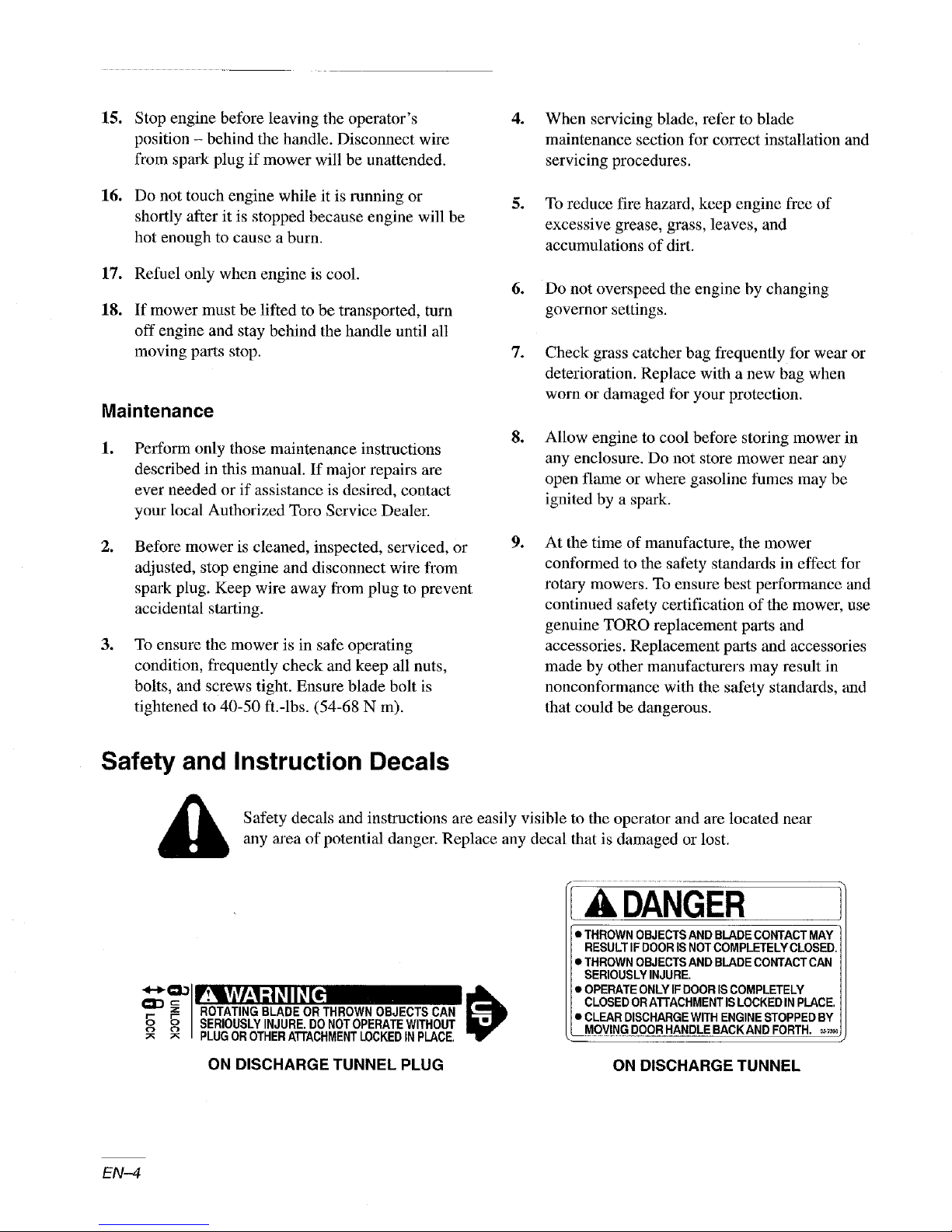
Safety and Instruction Decals
Safety decals and instructions are easily visible to the operator and are located near
any area of potential danger. Replace any decal that is damaged or lost.
°° °° I SERIOUSLYINJURE. DO NOTOPERATEWITHOUT
_ PLUGOROTHERATTACHMENTLOCKEDINPLACE.
ON DISCHARGE TUNNEL PLUG
EN-4
A DANGER
• THROWN OBJECTSAND BLADECONTACT MAY
RESULTIFDOORIS NOTCOMPLETELY CLOSED.
• THROWN OBJECTS AND BLADE CONTACT CAN
SERIOUSLY INJURE.
• OPEFIATEONLYIF DOOR IS COMPLETELY
CLOSED ORATrACHMENT IS LOCKEDIN PLACE.
• CLEAR DISCHARGEWrIH ENGINESTOPPED BY
MOVINGDOOR HANDLE BACKAND FORTH. _,_
ON DISCHARGETUNNEL
Page 19
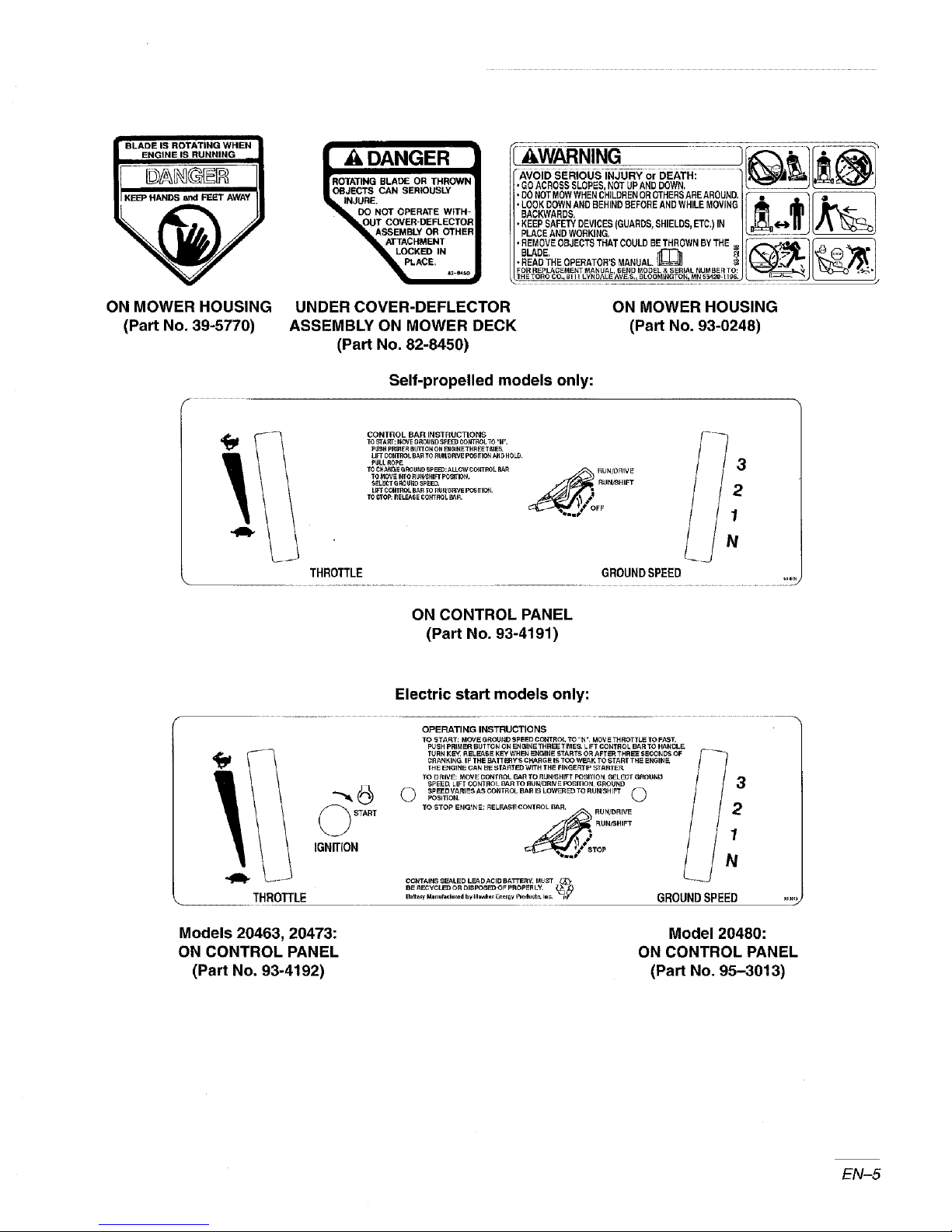
| ADANGER
IrROTATING BLADE OR THROWI_
OBJECTS CAN SERIOUSLY
_ll_J/JURE.
"_L DO NOT OPERATE W_TH-
"_kOUT COVER-DEFLECTOR
ASSEMBLY OR OTHER
LOCKED IN
_ACE, _-_.
ON MOWER HOUSING
(Part No. 39-5770)
THROTTLE
UNDER COVER-DEFLECTOR
ASSEMBLY ON MOWER DECK
ON MOWER HOUSING
(Part No. 93-0248)
(Part No. 82-8450)
Self-propelled models only:
CONTROL BAR INSTRUCTIONS
TO _TA _: MOVE G ROUND SpEE_ COb_TROL TO "lP.
p_SH P_IER BUTrOf_ OR _GINETHREET_tES.
rIFT CONTROL BAR T_3 RUt_RNE pO6fflON A_D HOLO
P_LL ROPE
$_L_T6_UNO SP_. • RtlNiNtlFT
TO CHA_E QRQUND SPEED:ALLOWCOkTROL BAR _ RUN/ORIVE
TO _roP: RE_6E CO_L _R.
THROTTLE GROUNDSPEED
ON CONTROL PANEL
(Part No. 93-4191)
Electric start models only:
OPERATING INSTRUCTIONS
TO START: MOVE GROUND SPEED CCNTROL TO "N ', MOVE THROTTLE TO FAST.
PUSH PRIME_ BUTT(_N CN EN CiIN E THREE TIMES. LEFT CONTROL BAR TO HANDLE
TURN KE_ RELEASE KEY WHEN II_JGINE STARTS OR AFTER TRRE_ $E_JDS OF
CRANKING IF THE _ATT_RYS CHARGE IS TOO WF..AK TO START THE ENGINE,
_HE ENGINE CAN BE STARTED WITH THE FINGERTIP STA_TEF_
TO D RIV_: MOVE CONTROL BAR TO R LIN_ HIFT POSITIOhL SELECT GROUI_D
SPEED LIFT CONTROL _ TO R_WDRN E POSITION GROUND
©
POSiT[O_SPEEDVAR_ AS CONTROL BAR I_ LOW_ E_) TO RUWSHIFT @
TO STOP _NGtIN _: RELF.AS_ (_ONTROL BAR, RUN/DRIV E _--_
_ START
IGNITION
_ RUN/SHIFT
CCI_'rAIP_,_SEALED LEADACID BATi'I_RV,MU_T _,
BE RECYCLED OR DISI=O_ O_ PROp_ L'L
o, 1
"m_ N
1
I
N
GROUNDSPEED ,-_
Models 20463, 20473:
ON CONTROL PANEL
(Part No. 93-4192)
Model 20480:
ON CONTROL PANEL
(Part No. 95-3013)
EN-5
Page 20
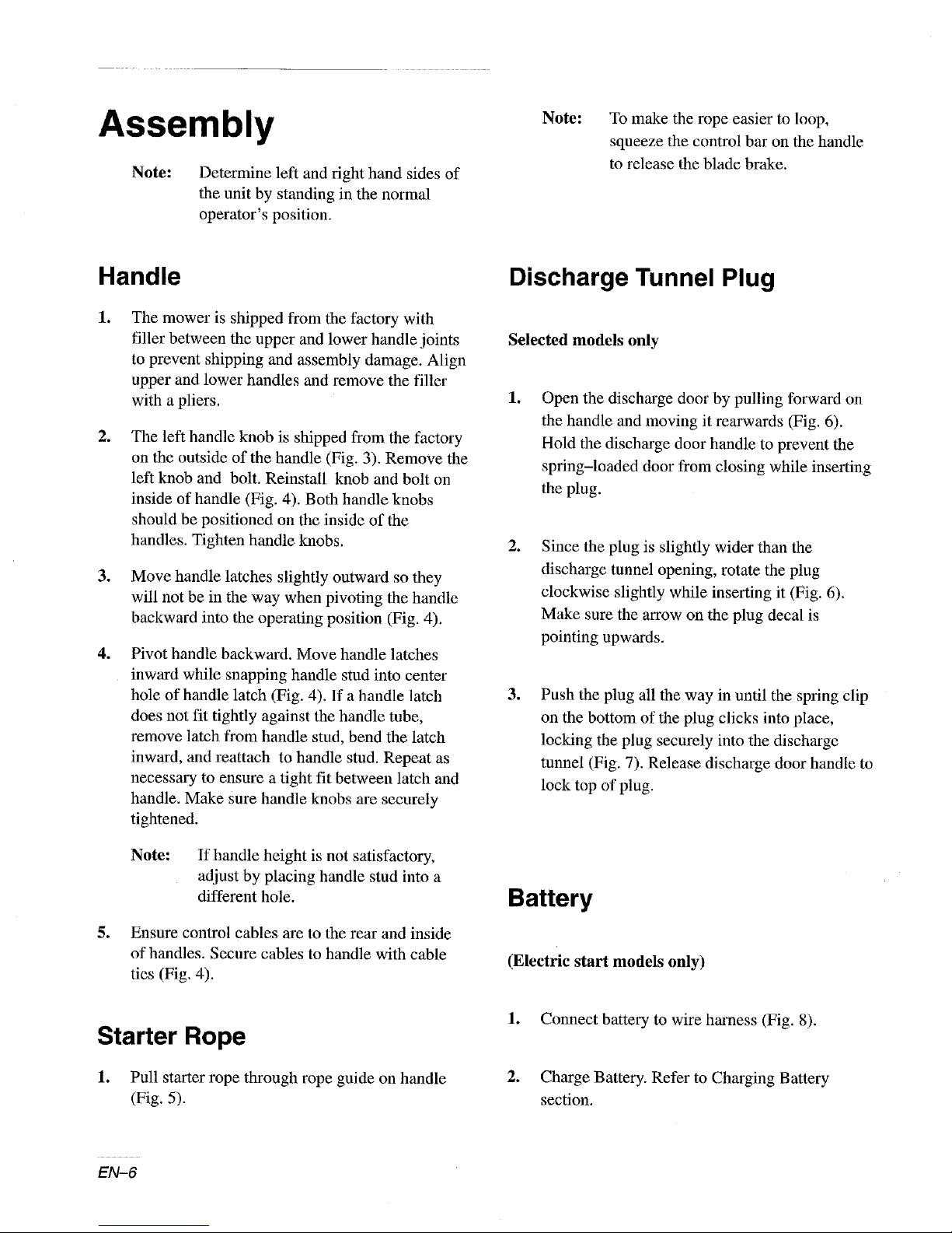
Assembly
Note: Determine left and right hand sides of
the unit by standing in the normal
operator's position.
Note:
To make the rope easier to loop,
squeeze the control bar on the handle
to release the blade brake.
Handle
lo
The mower is shipped from the factory with
filler between the upper and lower handle joints
to prevent shipping and assembly damage. Align
upper and lower handles and remove the filler
with a pliers.
.
The left handle knob is shipped from the factory
on the outside of the handle (Fig. 3). Remove the
left knob and bolt. Reinstall knob and bolt on
inside of handle (Fig. 4). Both handle knobs
should be positioned on the inside of the
handles. Tighten handle knobs.
.
Move handle latches slightly outward so they
will not be in the way when pivoting the handle
backward into the operating position (Fig. 4).
°
Pivot handle backward. Move handle latches
inward while snapping handle stud into center
hole of handle latch (Fig. 4). If a handle latch
does not fit tightly against the handle tube,
remove latch from handle stud, bend the latch
inward, and reattach to handle stud. Repeat as
necessary to ensure a tight fit between latch and
handle. Make sure handle knobs are securely
tightened.
Discharge Tunnel Plug
Selected models only
lo
Open the discharge door by pulling forward on
the handle and moving it rearwards (Fig. 6).
Hold the discharge door handle to prevent the
spring-loaded door from closing while inserting
the plug.
.
Since the plug is slightly wider than the
discharge tunnel opening, rotate the plug
clockwise slightly while inserting it (Fig. 6).
Make sure the arrow on the plug decal is
pointing upwards.
o
Push the plug all the way in until the spring clip
on the bottom of the plug clicks into place,
locking the plug securely into the discharge
tunnel (Fig. 7). Release discharge door handle to
lock top of plug.
Note: If handle height is not satisfactory,
adjust by placing handle stud into a
different hole.
5. Ensure control cables are to the rear and inside
of handles. Secure cables to handle with cable
ties (Fig. 4).
Starter Rope
1. Pull starter rope through rope guide on handle
(Fig. 5).
EN-6
Battery
(Electric start models only)
1. Connect battery to wire harness (Fig. 8).
0
Charge Battery. Refer to Charging Battery
section.
Page 21
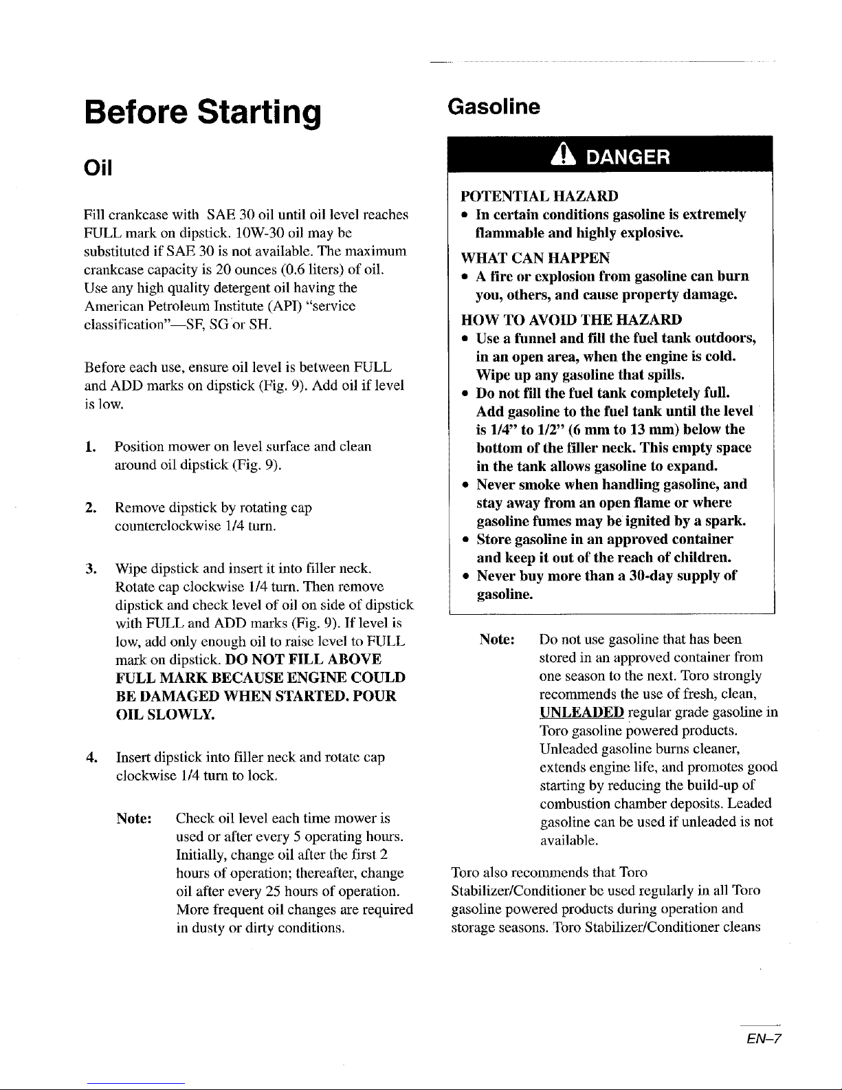
Before Starting
Oil
Fill crankcase with SAE 30 oil until oil level reaches
FULL mark on dipstick. 10W-30 oil may be
substituted if SAE 30 is not available. The maximum
crankcase capacity is 20 ounces (0.6 liters) of oil.
Use any high quality detergent oil having the
American Petroleum Institute (API) "service
elassification"--SF, SG or SH.
Before each use, ensure oil level is between FULL
and ADD marks on dipstick (Fig. 9). Add oil if level
is low.
1. Position mower on level surface and clean
around oil dipstick (Fig. 9).
2. Remove dipstick by rotating cap
counterclockwise 1/4 turn.
.
Wipe dipstick and insert it into filler neck.
Rotate cap clockwise 1/4 turn. Then remove
dipstick and check level of oil on side of dipstick
with FULL and ADD marks (Fig. 9). If level is
low, add only enough oil to raise level to FULL
mark on dipstick. DO NOT FILL ABOVE
FULL MARK BECAUSE ENGINE COULD
BE DAMAGED WHEN STARTED. POUR
OIL SLOWLY.
4. Insert dipstick into filler neck and rotate cap
clockwise 1/4 turn to lock.
Note: Check oil level each time mower is
used or after every 5 operating hours.
Initially, change oil after the first 2
hours of operation; thereafter, change
oil after every 25 hours of operation.
More frequent oil changes are required
in dusty or dirty conditions.
Gasoline
POTENTIAL HAZARD
• In certain conditions gasoline is extremely
flammable and highly explosive.
WHAT CAN HAPPEN
• A fire or explosion from gasoline can burn
you, others, and cause property damage.
HOW TO AVOID THE HAZARD
• Use a funnel and fill the fuel tank outdoors,
in an open area, when the engine is cold.
Wipe up any gasoline that spills.
• Do not fill the fuel tank completely full.
Add gasoline to the fuel tank until the level
is 1/4" to 1/2" (6 mm to 13 mm) below the
bottom of the filler neck. This empty space
in the tank allows gasoline to expand.
• Never smoke when handling gasoline, and
stay away from an open flame or where
gasoline fumes may be ignited by a spark.
• Store gasoline in an approved container
and keep it out of the reach of children.
• Never buy more than a 30-day supply of
gasoline.
Note:
Toro also recommends that Toro
Stabilizer/Conditioner be used regularly in all Toro
gasoline powered products during operation and
storage seasons. Toro Stabilizer/Conditioner cleans
Do not use gasoline that has been
stored in an approved container from
one season to the next. Toro strongly
recommends the use of fresh, clean,
UNLEADED regular grade gasoline in
Toro gasoline powered products.
Unleaded gasoline burns cleaner,
extends engine life, and promotes good
starting by reducing the build-up of
combustion chamber deposits. Leaded
gasoline can be used if unleaded is not
available.
EN-7
Page 22
the engine during operation and prevents gum-like
varnish deposits fl'om forming in the engine during
periods of storage.
IMPORTANT: Do not mix oil with the
gasoline. Never use methanol, gasoline
containing methano|, gasohol containing
more than 10% ethanol or white gas because
engine fuel system damage could result.
Do not use fuel additives other than those
manufactured for fuel stabilization during
storage such as Ibro's Stabilizer/conditioner
or a similar product. Toro's
Stabilizer/conditioner is a petroleum distillate
based conditioner/stabilizer. Toro does not
recommend stabilizers with an alcohol base
such as ethanol, methanol or isopropyl.
Additives should not be used to try to
enhance the power or performance of
machine.
1. Clean around fuel tank cap and remove cap from
tank (Fig. 9).
2. Using unleaded gasoline, fill fuel tank to within
114" to 112" (6 to 13 mm) from top of tank, not
into filler neck. Do not fill tank full.
3. Reinstall fuel tank cap and wipe up any spilled
gasoline.
4. Connect spark plug wire (if disconnected)
(Fig. 9).
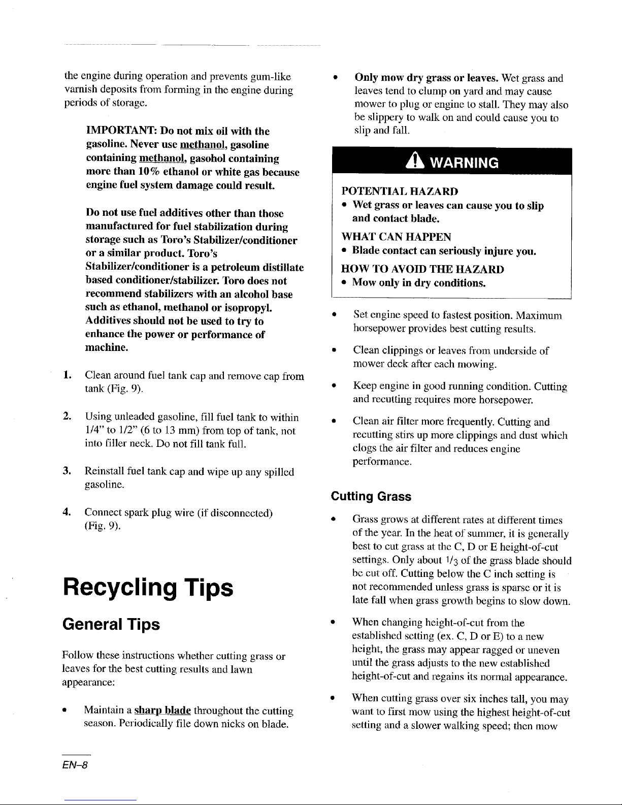
Recycling Tips
Only mow dry grass or leaves. Wet grass and
leaves tend to clump on yard and may cause
mower to plug or engine to stall. They may also
be slippery to walk on and could cause you to
slip and fall.
POTENTIAL HAZARD
• Wet grass or leaves can cause you to slip
and contact blade.
WHAT CAN HAPPEN
• Blade contact can seriously injure you.
HOW TO AVOID THE HAZARD
• Mow only in dry conditions.
Set engine speed to fastest position. Maximum
horsepower provides best cutting results.
Clean clippings or leaves from underside of
mower deck after each mowing.
Keep engine in good running condition. Cutting
and recutting requires more horsepower.
Clean air filter more frequently. Cutting and
recutting stirs up more clippings and dust which
clogs the air filter and reduces engine
performance.
Cutting Grass
Grass grows at different rates at different times
of the year. In the heat of summer, it is generally
best to cut grass at the C, D or E height-of-cut
settings. Only about 1/3 of the grass blade should
be cut off. Cutting below the C inch setting is
not recommended unless grass is sparse or it is
late fall when grass growth begins to slow down.
General Tips
Follow these instructions whether cutting grass or
leaves for the best cutting results and lawn
appearance:
a Maintain a sharp blade throughout the cutting
season. Periodically file down nicks on blade.
EN-8
When changing height-of-cut from the
established setting (ex. C, D or E) to a new
height, the grass may appear ragged or uneven
until the grass adjusts to the new established
height-of-cut and regains its normal appearance.
When cutting grass over six inches tall, you may
want to first mow using the highest height-of-cut
setting and a slower walking speed; then mow
Page 23
again at a lower setting for best lawn appearance.
If grass is too long and leaves clumps on top of
lawn, mower may plug and cause engine to stall.
Operation
Controls
• Alternate mowing direction. This helps disperse
clippings over lawn for even fertilization.
If the finished cut lawn appearance is unsatisfactory,
try one or more of the following:
* Sharpen Ihe blade.
• Walk at a slower pace while mowing.
• Raise the height-of-cut setting on your mower.
• Cut grass more frequently.
• Overlap cutting swaths instead of cutting a full
swath with each pass.
Set height-of-cut on front wheels one notch
lower than rear wheels. (example: set front
wheels at "C" setting and rear wheels at "D"
setting)
Cutting Leaves
When cutting is complete, always be sure that
50% of the lawn shows through the cut leaf
cover. This may require one or more passes over
the leaves.
• For light leaf coverage, position all wheels at the
same height-of-cut setting.
If there are more than five inches of leaves Oll
lawn, set the front wheels one or two notches
higher than the rear wheels. This makes it easier
to feed leaves under mower deck.
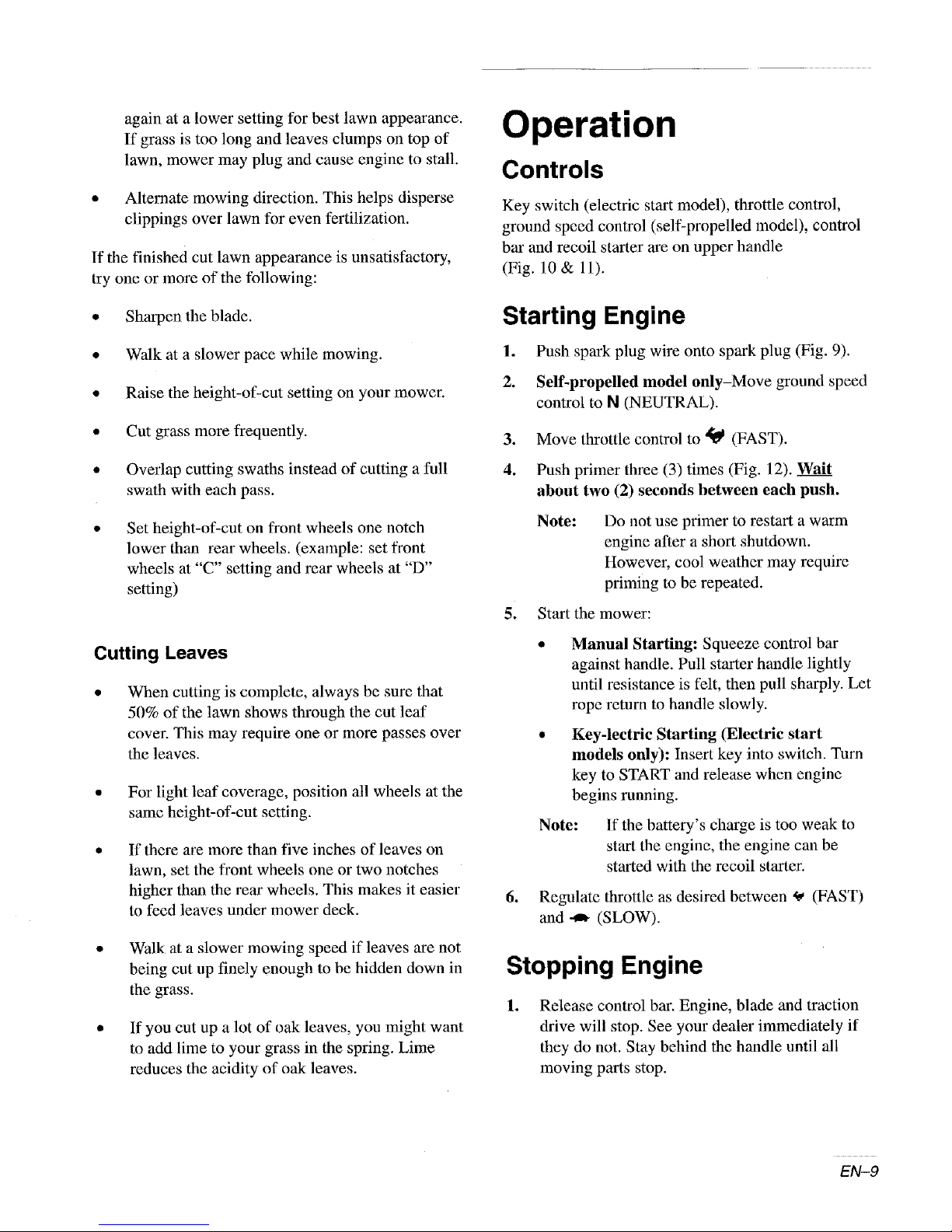
Key switch (electric start model), throttle control,
ground speed control (self-propelled model), control
bar and recoil starter are on upper handle
(Fig. 10 & 11).
Starting Engine
I. Push spark plug wire onto spark plug (Fig. 9).
2. Self-propelled model only-Move ground speed
control to N (NEUTRAL).
3. Move throttle control to _ (FAST).
4. Push primer three (3) times (Fig. 12). _Wait
about two (2) seconds between each push.
Note: Do not use primer to restart a warm
engine after a short shutdown.
However, cool weather may require
priming to be repeated.
5. Start the mower:
• Manual Starting: Squeeze control bar
against handle. Pull starter handle lightly
until resistance is felt, then pull sharply. Let
rope return to handle slowly.
• Key-lectric Starting (Electric start
models only): Insert key into switch. Turn
key to START and release when engine
begins running.
Note:
6. Regulate throttle as desired between _ (FAST)
and -_ (SLOW).
If the battery's charge is too weak to
start the engine, the engine can be
started with the recoil starter.
• Walk at a slower mowing speed if leaves are not
being cut up finely enough to be hidden down in
the grass.
• If you cut up a lot of oak leaves, you might want
to add lime to your grass in the spring. Lime
reduces the acidity of oak leaves.
Stopping Engine
.
Release control bar. Engine, blade and traction
drive will stop. See your dealer immediately if
they do not. Stay behind the handle until all
moving parts stop.
EN-9
Page 24
2. Pull wire off spark plug if mower will be
unattended or not used. Remove key from switch
on electric start model.
pulling the mower rearward. The mower may need to
be pushed forward one inch or more after control bar
has been released to disengage the self-propelled
drive and disengage the clutches.
Self-propelled Drive
(Self-propelled models only)
The mower has three ground speeds: number "1" is
slow, "2" is medium, and "3" is a fast walking pace.
1. Move control bar to the RUN/SHIFF position
(Fig. 13).
2. Move ground speed control to desired setting.
3. To engage the self-propel drive, squeeze the
control bar against the handle to the
RUN/DRIVE position (Fig. 13).
Note:
Ground speed can be varied by increasing or
decreasing distance between control bar and handle.
Lower control bar to slow mower when making a turn
or if mower is moving too fast for you. If you lower
control bar too far, the mower will stop
self-propelling. Squeeze control bar closer to handle
to increase ground speed. When control bar is tight
against handle, mower will self-propel at maximum
ground speed. Move ground speed control to
N (NEUTRAL) when using the mower for trimming
and whenever leaving mower.
Pulling Mower Rearward
(Self-propelled models only)
Your mower is equipped with free-wheeling clutches
which make it easier to pull the mower rearward. The
control bar must be lowered enough to disengage the
self-propelled drive and disengage the clutches before
Do not shift speeds while control bar is
squeezed against handle in the
RUN/DRIVE position (Fig. 13); the
transmission could be damaged. Move
control bar to the RUN/SHIFr position
when changing ground speed.
For example, if you arc approaching an object such as
a tree or bush from which you want to pull back the
mowel, lower the control bar just enough to
disengage the traction drive when the mower is about
six inches away from the object. The momentum of
the mower should carry it forward at least one inch
which will disengage the clutches. Then you should
be able to easily pull the mower rearward.
The self-propelled cable should be properly adjusted
so that you can lower the control bar comfortably to
stop the traction drive without stopping the engine.
See Self propelled Cable section in the Maintenance
chapter for cable adjustment information. If you need
help, see your Authorized Toro Service Dealer.
Using Discharge Tunnel Plug
Selected models only
.
Make sure engine is off. Open the discharge door
by pulling forward on the handle and moving it
rearwards (Fig. 6). Hold the discharge door
handle to prevent the spring-loaded door t?om
closing while inserting the plug.
2,
Since the plug is slightly wider thin1 the
discharge tunnel opening, you must rotate the
plug clockwise slightly while inserting it
(Fig. 6). Make sure the arrow on the plug decal
is pointing upwards.
3,
Push the plug all the way in until the spring clip
on the bottom of the plug clicks into place,
locking the plug securely into the discharge
tunnel (Fig. 7). Release the discharge door
handle to lock the top of the plug.
.
To remove the plug, move the discharge door
handle rearwards while at the same time lift up
the spring clip on the bottom of the plug. When
the plug is unlocked, pull it out of the discharge
tunnel.
EN-IO
Page 25

Note:
When grass is thick and lush, clippings
may collect on and around the
discharge tunnel plug. This may make
plug removal difficult. Clean plug
thoroughly after each use. Refer to
Cleaning, page 18.
Using Optional Grass Bag or
Side Discharge Chute
Selected models only
Occasionally you may wish to use the grass bag for
bagging extra long grass, lush grass or leaves.
1. Stop engine and wait for all moving parts to
stop.
2. Ensure discharge door handle is fully forward
and pin is engaged in catch (Fig. 14).
3. A. INSTALLING BAG-- Slide hole in bag
frame onto retaining post on discharge tunnel
(Fig. 14). Set rear of bag frame onto support rod.
B. INSTALLING THE SIDE DISCHARGE
CHUTE -- Slide the hole in discharge chute
frame onto the retaining post on the discharge
tunnel (Fig. 34).
POTENTIAL HAZARD
• A worn grass bag could allow small stones
and other similar debris to be thrown in
operator's or bystander's direction.
WHAT CAN HAPPEN
• Thrown objects can cause serious personal
injury or death to operator or bystanders.
HOW TO AVOID THE HAZARD
• Check the grass bag frequently. If it is
damaged, install a new genuine TORt
replacement bag.
POTENTIAL HAZARD
• Thrown objects may result if discharge
door does not close completely.
WHAT CAN HAPPEN
• Thrown objects can cause serious personal
injury or death.
HOW TO AVOID THE HAZARD
• If discharge door cannot be closed because
grass clippings clog discharge area, stop
engine and gently move discharge door
handle back and forth until door can be
dosed completely. If door still cannot be
dosed, remove obstruction with a stick, not
your hand.
POTENTIAL HAZARD
• Grass clippings and other objects can be
thrown from an open discharge tunnel.
WHAT CAN HAPPEN
• Objects thrown with enough force could
cause serious personal injury or death to
operator or bystander.
HOW TO AVOID THE HAZARD
• Never open door on discharge tunnel when
engine is running unless the optional grass
bag, optional side discharge attachment or
discharge tunnel plug is securely installed.
o
Pull discharge door handle forward until pin
clears catch and move handle rearward until pin
locks in bag notch (Fig. 15). Discharge door in
mower housing is now open.
.
EMPTYING BAG--Stop engine and wait for all
moving parts to stop. Lift discharge door handle
straight up and move it forward to engage the
locking pin with catch (Fig. 14). Grasp bag
frame handle and rear of bag and lift bag off
mower. Gradually tip bag lbrward to empty
clippings.
6. To reinstall bag, repeat steps 3-4.
EN-11
Page 26
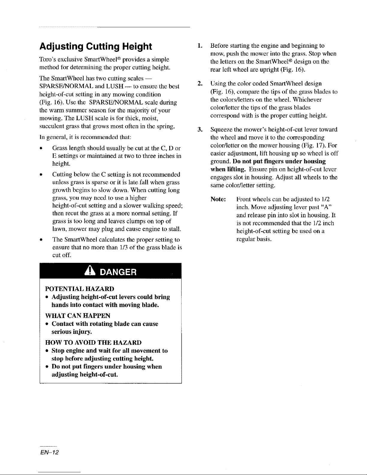
Adjusting Cutting Height
Tom's exclusive SmartWheel ® provides a simple
method for determining the proper cutting height.
The SmartWheel has two cutting scales --
SPARSE/NORMAL and LUSH -- to ensure the best
height-of-cut setting in any mowing condition
(Fig. 16). Use the SPARSE/NORMAL scale during
the warm summer season for the majority of your
mowing. The LUSH scale is for thick, moist,
succulent grass that grows most often in the spring.
In general, it is recommended that:
• Grass length should usually be cut at the C, D or
E settings or maintained at two to three inches in
height.
• Cutting helow tile C setting is not recommended
unless grass is sparse or it is late fall when grass
growth begins to slow down. When cutting long
grass, you may need to use a higher
height-of-cut setting and a slower walking speed;
then recur the grass at a more normal setting. If
grass is too long and leaves clumps on top of
lawn, mower may plug and cause engine to stall.
• The SmartWheel calculates the proper setting to
ensure that no more than 1/3 of the grass blade is
cut off.
.
Before starting the engine and beginning to
mow, push the mower into the grass. Stop when
the letters on the SmartWheel ® design on the
rear left wheel are upright (Fig. 16).
.
Using the color coded SmartWheel design
(Fig. 16), compare the tips of the grass blades to
the colors/letters on the wheel. Whichever
color/letter the tips of the grass blades
correspond with is the proper cutting height.
.
Squeeze the mower's height-of-cut lever toward
the wheel and move it to the corresponding
color/letter on the mower housing (Fig. 17). For
easier adjustment, lift housing up so wheel is off
ground. Do not put fingers under housing
when lifting. Ensure pin on height-of-cut lever
engages slot in housing. Adjust all wheels to the
same color/letter setting.
Note: Front wheels can be adjusted to 1/2
inch. Move adjusting lever past "A"
and release pin into slot in housing, It
is not recommended that the 1/2 inch
height-of-cut setting be used on a
regular basis.
POTENTIAL HAZARD
• Adjusting height-of-cut levers could bring
hands into contact with moving blade.
WHAT CAN HAPPEN
• Contact with rotating blade can cause
serious injury.
HOW TO AVOID THE HAZARD
• Stop engine and wait for all movement to
stop before adjusting cutting height.
• Do not put fingers under housing when
adjusting height-of-cut.
EN-12
Page 27
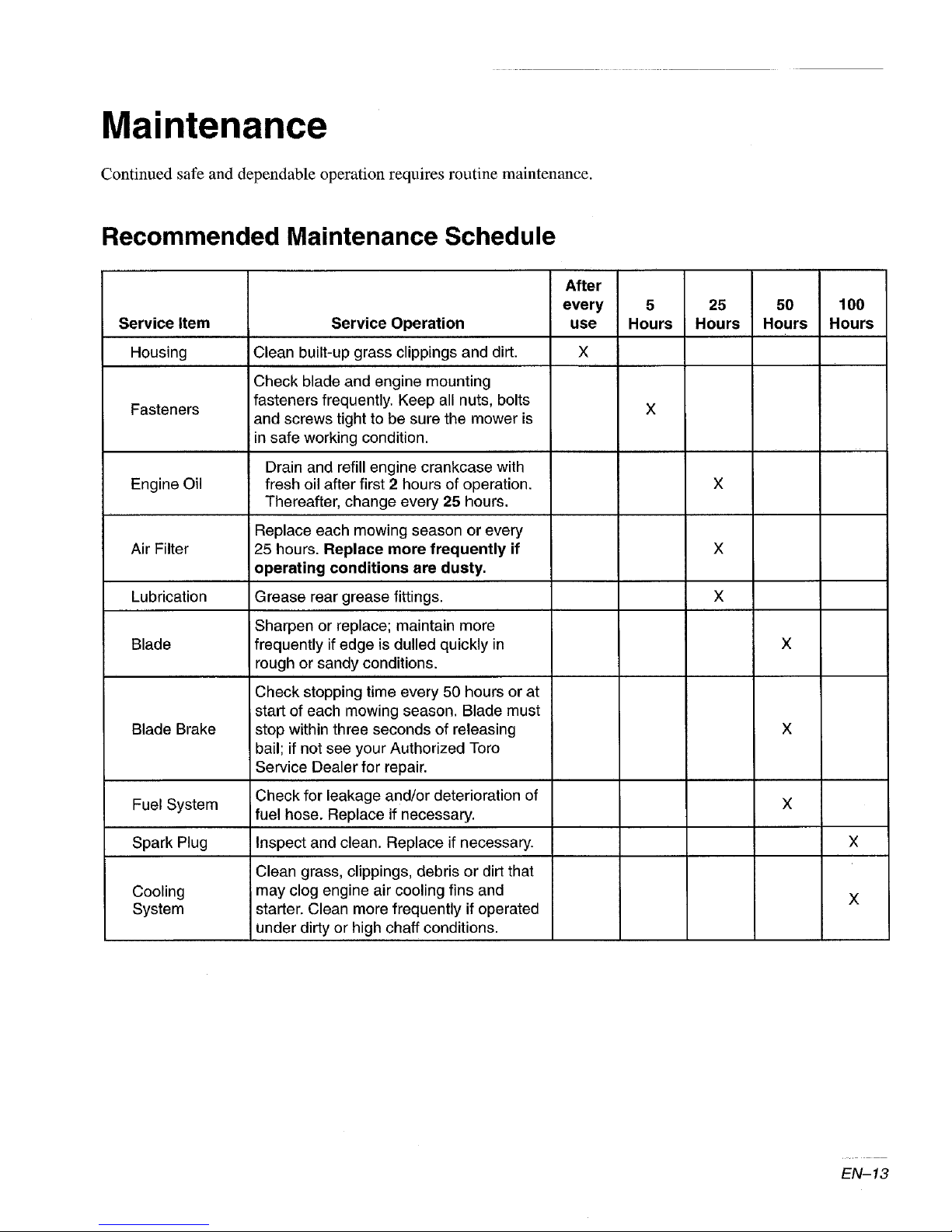
Maintenance
Continued safe and dependable operation requires routine maintenance.
Recommended Maintenance Schedule
every
Service Item
Service Operation
After
use
5
Hours25Hours
50 100
Hours Hours
Housing
Fasteners fasteners frequently. Keep all nuts, bolts X
Engine Oil fresh oil after first 2 hours of operation. X
Air Filter 25 hours. Replace more frequently if X
Lubrication Grease rear grease fittings. X
Blade frequently if edge is dulled quickly in
Blade Brake
Fuel System Check for leakage and/or deterioration of
Spark Plug Inspect and clean. Replace if necessary.
Clean built-up grass clippings and dirt. X
Check blade and engine mounting
and screws tight to be sure the mower is
m safe working condition.
Drain and refill engine crankcase with
Thereafter, change every 25 hours.
Replace each mowing season or every
operating conditions are dusty.
Sharpen or replace; maintain more
rough or sandy conditions.
Check stopping time every 50 hours or at
start of each mowing season. Blade must
stop within three seconds of releasing
bail; if not see your Authorized Toro
Service Dealer for repair.
fuel hose. Replace if necessary.
x
x
x
x
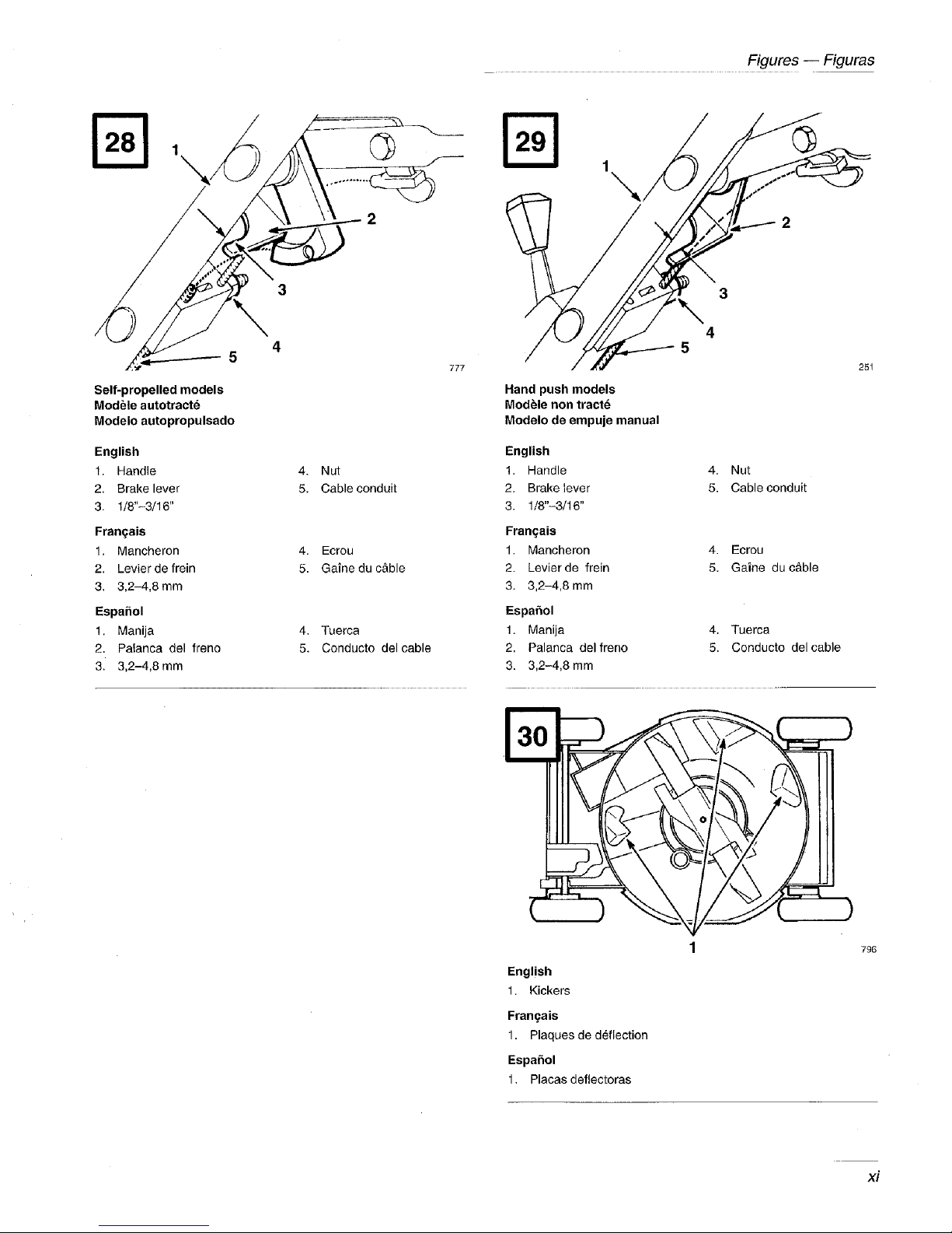
Clean grass, clippings, debris or dirt that
Cooling ;may clog engine air cooling fins and
System starter. Clean more frequently if operated
under dirty or high chaff conditions.
x
EN-13
Page 28
POTENTIAL HAZARD
• If you leave the wire on the spark plug, someone could start the engine.
WHAT CAN HAPPEN
• Accidental starting of engine could seriously injure you or other bystanders.
HOW TO AVOID THE HAZARD
• Pull wire off spark plug before you do any maintenance. Also push wire aside so it
does not accidentally contact spark plug.
Air Filter (Fig. 18)
Replace air filter once every season or every 25
hours; replace more frequently under dusty
conditions.
IMPORTANT: Do not operate engine without
air filter element; extreme engine wear or
damage will occur.
Note: Tipping mower on wrong side to
service underside of mower may cause
damage to air filter.
1. Stop engine and pull wire off spark plug (Fig. 9).
Remove key from switch on electric start model.
2. Loosen screw securing air cleaner cover to
engine. Tilt cover down and clean thoroughly.
3. Remove paper air filter and discard.
4. Insert a new paper air cleaner filter.
IMPORTANT: Do not try to vacuum or blow
dirt out of a dirty paper filter. Always replace
a dirty filter with a new one.
5. Reinstall air cleaner cover and secure with screw.
IMPORTANT: Drain gasoline from a cold
engine only.
.
Remove cap from fuel tank and use pump-type
syphon to drain fuel into clean gas can.
Note: This is the only procedure
recommended for draining fuel.
Change Engine Oil
Change engine oil after first 2 hours of operation and
after 25 hours of operation thereafter.
POTENTIAL HAZARD
• Tipping mower may cause fuel leakage
from carburetor or fuel tank.
WHAT CAN HAPPEN
• Gasoline is extremely flammable, highly
explosive and under certain conditions can
cause personal injury or property damage.
HOW TO AVOID THE HAZARD
• Avoid fuel spills by running engine dry or
remove gas with hand pump, never siphon.
Drain Gasoline
1. Stop engine and wait for engine to cool. Pull
wire off spark plug (Fig. 9). Remove key from
switch on electric start model.
EN-14
.
Stop engine and pull wire off spark plug (Fig. 9).
Remove key from switch on electric start model.
.
Drain gasoline fl'om fuel tank. See Drain
Gasoline section.
Page 29
Note: The oil should be warm before
draining. Warm oil flows better and
carries more contaminants than cold
oil.
No
Even though the gasoline has been drained tTom
the engine, enough fuel should be left in the
carburetor bowl and fuel line to start the engine.
Reinstall the spark plug wire onto the spark
plug. For electric start models, insert key into
switch. Start the engine and let it run until it runs
out of fuel. Briefly running the engine will warm
up the oil.
.
Tip mower on left side.
5.
Drain oil from oil fill tube at dipstick (Fig. 19).
Drain oil into appropriate container. Dispose of
oil properly. Recycle per local codes.
.
Turn mower upright.
7.
Fill crankcase to FULL line on dipstick with
fi'esh oil. See Before Starting chapter, Oil section
for specifications.
.
Check oil level and reinstall dipstick.
.
Set spark plug gap at .030 inch (.76 ram)
(Fig. 20).
.
Install spark plug by hand, then torque to
15 ft.-lbs. (20 N.m) (Fig. 20).
)
Reconnect spark plug wire when maintenance is
completed.
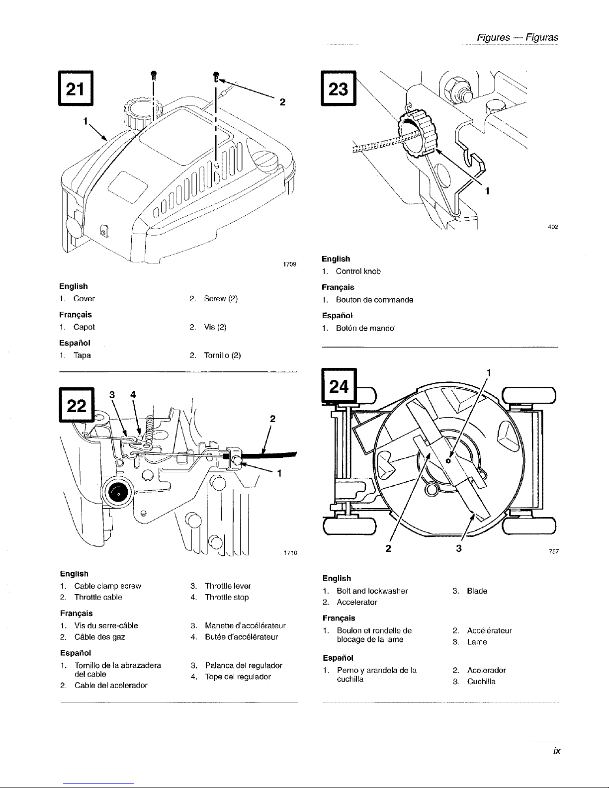
Throttle Cable
Throttle control adjustment may be required if engine
does not start or stop. Whenever a new throttle
conta'ol cable is installed, throttle must be adjusted.
1. Stop engine and pull wire off spark plug (Fig. 9).
Remove key from switch on electric start model.
2. Remove (2) screws from engine cover and lift
off cover (Fig. 21).
3. Loosen cable clamp screw until throttle cable
slides (Fig. 22).
4. Move throttle control to f0 (FAST) position.
5. Move throttle cable until throttle lever contacts
stop (Fig. 22).
9.
Wipe up any spilled oil.
Spark Plug
A spark plug that is dirty, pitted, carbon-covered or
has worn electrodes may cause hard starting and poor
operation.
Replace spark plug once a season or clean every 100
hours, whichever occurs first. Use a Champion
RJ19LM spark plug or equivalent.
1. Pull wire off spark plug (Fig. 9). Remove key
from switch on electric start model.
o
Remove spark plug and clean with a wire brush,
removing carbon build-up. DO NOT SAND
BLAST. Check condition of plug for cracks and
damaged or worn electrodes. Replace if
necessary.
6. Tighten cable clamp screw to lock adjustment in
place.
7. Reinstall engine cover with (2) screws. Torque
screws to 8-10 in.-lbs. (.9-1.1 N-m)
Self-propelled Cable
Selected models only
If mower does not self-propel or has a tendency to
creep forward when traction is not engaged, adjust
wheel drive control knob on rear of gear box
(Fig. 23).
lo
Stop engine and pull wire off spark plug (Fig. 9).
Remove key from switch on electric start model.
Rotate control knob clockwise 1/2 turn if mower
o
does not self-propel. If mower creeps forward,
rotate knob 1/2 turn counterclockwise to loosen
belt.
EN-15
Page 30

3. SLowly pull mower backward while control bar
is gradually moved toward handle. Adjustment is
correct when:
• mower does not creep forward when traction is
disengaged
control bar is at a comfortable operating distance
from the handle for operator's hand when
disengaging and engaging the self-propelled
drive.
Note:
Do not overadjust cable. Cable should
be just tight enough to make wheels
tuna when control bar is at a distance
t'rom the handle that is comfortable for
operator's hand. Overadjnsting may
require excessive operator el'fort to
engage or disengage self-propelled
drive.
If you need help, see your Authorized Toro Service
Dealer.
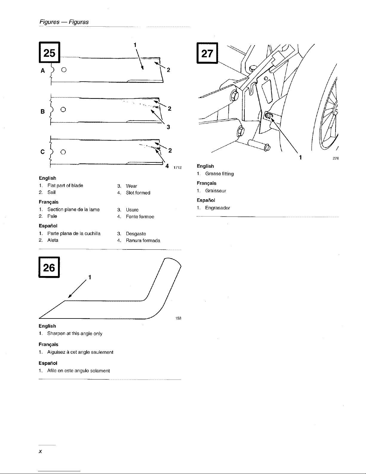
Blade
A straight sharp blade provides maximum cutting
performance. Regularly inspect and sharpen blade.
.
Tip mower on its left side (Fig. 24).
4.
INSPECTING BLADE--Carefully examine
blade for sharpness and wear, especially where
fiat and curved parts meet (Fig. 25). Since sand
and abrasive material can wear away the metal
that connects the fiat and curved parts of the
blade, check blade before using the mower. If a
slot or wear is noticed, (Fig. 25B & C), replace
blade. Refer to step 5.
.
REMOVING BLADE--Grasp end of blade
using a rag or thickly padded glove. Remove
blade bolt, lock washer, accelerator, and blade
(Fig. 24).
POTENTIAL HAZARD
• A worn or damaged blade could break and
a piece of blade could be thrown in
operator's or bystander's direction.
WHAT CAN HAPPEN
• A thrown piece of blade could cause serious
personal injury or death to operator or
bystanders.
HOW TO AVOID THE HAZARD
• Inspect blade periodically for wear or
damage.
• Replace a worn or damaged blade.
POTENTIAL HAZARD
• Blade is sharp.
WHAT CAN HAPPEN
• Contact with sharp blade can cause serious
personal injury.
HOW TO AVOID THE HAZARD
• Wear gloves or wrap sharp edges of tile
blade with a rag.
=
Stop engine and pull wire off spark plug (Fig. 9).
Remove key from switch on electric start model.
.
Drain gasoline fi'om fuel tank. See Drain
Gasoline section.
EN-16
Note:
For best performance, install new blade
betbre cutting season begins. During
the year, file down small nicks to
maintain the cutting edge.
,
SHARPENING BLADE--Using a file, sharpen
top side of blade (side facing mower housing)
and maintain original cutting angle (Fig. 26).
The blade will remain balanced if the same
amount of material is removed from both cutting
edges.
IMPORTANT: Check balance of blade by putting
it on a blade balancer. An inexpensive balancer
can be purchased at a hardware store. A balanced
blade will stay in a horizontal position and an
Page 31

unbalanced blade will settle to the heavy side. If
the blade is not balanced, file more metal oft'
cutting edge on heavy end of blade.
.
Install sharp, balanced blade, accelerator, lock
washer, and blade bolt. Sail part of blade must
point toward top of mower housing to assure
correct installation. Tighten the blade bolt to
40-50 ft-lb (54-68 N.m).
POTENTIAL HAZARD
• Operating mower without accelerator in
place could cause blade to flex, bend or
break.
WHAT CAN HAPPEN
• A broken blade could cause serious injury
or death to operator or bystanders.
HOW TO AVOID THE HAZARD
• Do not operate mower without accelerator.
Lubrication
After every 25 operating hours or when season ends,
front and rear wheels must be lubricated.
1. Apply 2 or 3 drops of light oil on inside and
outside of all wheel bolts. Spin wheels to
distribute oil into bushings. Wipe up excess oil.
.
Stop engine and pull wire off spark plug (Fig. 9).
Remove key from switch on electric start model.
.
CHECK ADJUSTMENT (Fig. 28 & 29)--Move
control bar toward handle until slack in wire is
removed. Gap between brake lever and handle
must be 118"-3/16". See step 3 for adjustment.
.
ADJUST CABLE CONDUIT (Fig. 28 &
29)--Loosen nut on cable bracket. Insert
1/8"-3116" object between brake lever and
handle. Pull down on cable conduit until all
slack is removed from wire. Then tighten nut.
Charging Battery
(Electric start models only)
Although a new battery is not fully charged, a partial
charge of 4 hours provides enough energy for several
starts. However, a new battery must be charged tbr 72
continuous hours to ensure full charge. Also, charge
battery for 72 hours when mower is stored and in the
spring. During normal operation, engine alternator
keeps battery charged.
1. Stop engine and disconnect wire harness from
battery terminal (Fig, 8).
.
If desired, battery can be removed by removing
(2) locknuts, (2) flat washers, and (2) carriage
bolts. However, removal is not required if
mower can be positioned near an electrical
outlet.
Self-propelled models only
.
Move rear wheel height-of-cut levers to "C"
setting. Wipe grease fittings with clean rag.
Install grease gun onto fitting and gently apply
two or three pumps of #2 Multi-Purpose
Lithium Base Grease (Fig. 27).
Blade Brake
Whenever a new blade brake cable assembly is
installed, an adjustment is required.
3,
Connect TORO electro charger to battery and
plug into 120VAC power outlet. After charging
battery for specified time, unplug charger and
disconnect from battery.
4, Connect wiring harness to battery terminal.
IMPORTANT'. Only the TORt electro
charger is recommended because other
chargers could damage the battery. Always
use charger indoors and charge battery at
room temperature (+70°F) whenever possible.
Do not charge battery longer than 72 hours
because damage could result.
EN-17
Page 32

Disposing of Battery
(Electric start models only)
DO NOT PLACE USED BATTERIES IN YOUR
REGULAR TRASH!
THIS SEALED LEAD (ACID) BATTERY MUST
BE COLLECTED, RECYCLED OR DISPOSED
OF IN AN ENVIRONMENTALLY SOUND
MANNER.
The incineration, landfilling or mixing of sealed lead
(acid) batteries with the municipal solid waste stream
is PROHIBITED BY LAW in some areas.
Return this battery to a federal or state approved
sealed lead (acid) battery recycler. THis may be
where you purchased the battery.
Contact your local waste management officials for
other information regarding the environmentally
sound collection, recycling and disposal of this
battery.
POTENTIAL HAZARD
• Grass clippings and other objects can be
thrown from an open discharge tunnel.
WHAT CAN HAPPEN
• Thrown objects can cause serious injury or
kill operator or bystanders.
HOW TO AVOID THE HAZARD
• Never start or operate the mower unless
one of the tbllowing is true:
1. The discharge tunnel plug is locked
securely in discharge tunnel.
2. The optional grass bag is locked in
place.
3. The optional side discharge chute is
locked in place.
4. The discharge tunnel door is closed.
Underside of Mower Housing
Cleaning
Plug
(Selected models only)
To ensure best performance, the discharge tunnel plug
must be cleaned after each use. When grass is thick
and lush, clippings may collect on and around the
plug; this may make plug removal difficult. After
each use, remove plug from discharge tunnel and
clean off all debris.
Discharge Tunnel
(Selected models only)
Always be sure that discharge tunnel door closes
securely when handle is released. If debris prevents
discharge door from closing securely, clean inside of
discharge tunnel and door thoroughly.
To ensure best pertbrmance, keep underside of mower
housing clean. Be especially careful to keep kickers
free of debris (Fig. 30).
Washing Method
Whenever the underside of the mower requires
cleaning, follow this procedure for washing debris out
fi'om underside of deck.
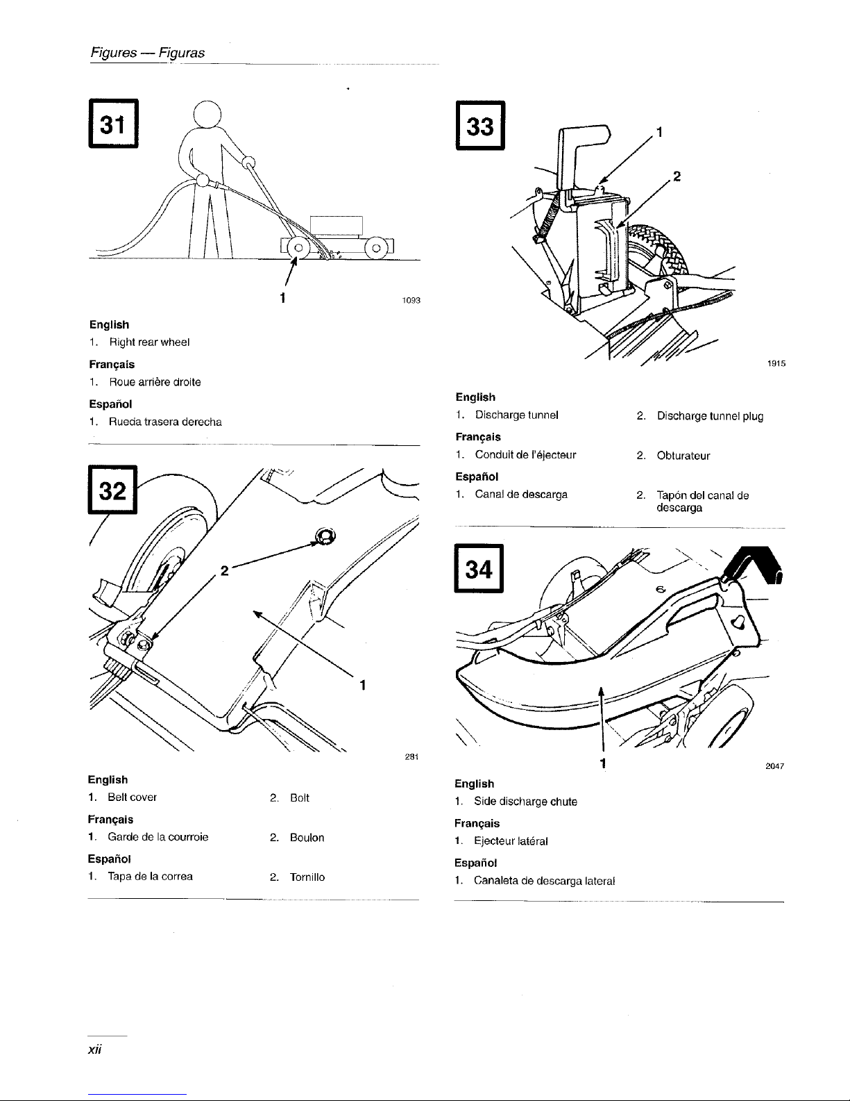
1. Position mower on a flat concrete or asphalt
surface near a garden hose.
2. Start the engine.
.
Hold the running garden hose at handle level mad
direct water to flow on ground just in front of
right rear tire (Fig. 31). The rotating blade will
draw water under the housing and wash out
clippings. Let the water run for a few minutes or
until you no longer see clippings being washed
out from under housing.
4. Stop the engine.
EN-18
Page 33

5. Turn off the garden hose.
1. Stop theengine.
o Restm_ mower and let it run for a few minutes to
dry out moisture on the mower and its
components. While the engine is running,
engage and disengage the traction drive several
times to dry it out.
Scrap_g Method
If washing does not remove all debris from under
deck, tip mower and scrape it clean.
1. Stop engine and pull wire off spark plug (Fig. 9).
Remove key from switch on electric start model.
2. Drain gasoline from fnel tank. See Drain
Gasoline section.
POTENTIAL HAZARD
• Gasoline is extremely flammable, highly
explosive and under certain conditions can
cause personal injury or property damage.
WHAT CAN HAPPEN
• Tipping mower may cause fuel leakage
from carburetor or fuel tank.
HOW TO AVOID THE HAZARD
• Avoid fuel spills by running engine dry or
remove gas with hand pump, never siphon.
3. Tip mower on its left side (Fig. 30).
4. Remove dirt and grass clippings with a
hardwood scraper. Avoid burrs and sharp edges.
5. Turn mower upright.
2. With engine turned off, remove bolts securing
belt cover (Fig. 32) to mower housing.
3. Lift off cover and brush out all debris from belt
area.
4. Reinstall belt cover.
Storage
To prepare lawn mower for off-season storage
perform recommended maintenance procedures. See
Maintenance chapter.
Store mower in a cool, clean, dry place. Cover mower
to keep it clean and protected.
Fuel
POTENTIAL HAZARD
• Gasoline can vaporize if stored over long
periods of time.
WHAT CAN HAPPEN
• Vaporized fuel can explode if it comes into
contact with open flame.
HOW TO AVOID THE HAZARD
• Do not store gasoline (fuel) over long
periods of time.
• Do not store mower with fuel in the tank in
an enclosure with an open flame. (Example:
furnace or water heater pilot light.)
• Allow the engine to cool before storing in
any enclosure.
6. Refill gas tank.
7. Reconnect spark plug wire.
Belt Cover
(Self-propelled models only)
Keep area under belt cover free of debris.
For long term storage, either drain gasoline from fuel
tank or use a fuel additive before storing. To drain
gasoline, see Draining Gasoline section. After fuel is
drained, start engine and let it idle until all fuel is
consumed and engine stops. Repeat the starting
procedure two more times to ensure all gas is
removed from the engine. If gasoline is not drained,
gum-like varnish deposits will form and cause poor
engine operation, even starting problems.
EN-19
Page 34

Fuel can be left in gas tank only if a fuel additive,
such as Toro's Stabilizer/Conditioner, is added to
gasoline before storing. Toro's Stabilizer/Conditioner
is a petroleum distillate based conditioner/stabilizer.
Toro does not recommend stabilizers with an alcohol
base, such as ethanol, methanol or isopropyl. Use fuel
additive in recommended quantities as specified on
container.
Engine
1. While engine is still warm, drain oil from
crankcase. See Maintenance chapter, Change
Engine Oil section.
.
Lubricate the wheels. See Maintenance chapter,
Lubrication section.
.
Charge battery. See Maintenance chapter,
Charging Battery section.
5. Touch up all rusted or chipped paint surfaces.
Removing From Storage
1,
Check and tighten all fasteners.
2.
Remove spark plug and spin engine rapidly
using starter to blow excess oil from the
cylinder. Clean spark plug or replace if cracked,
broken or electrodes are worn.
2. Remove spark plug. Using an oil can, squirt
about one tablespoon of oil through spark plug
hole.
3. Slowly rotate engine several times, using starter
rope, to distribute oil.
4. Reinstall spark plug but DO NOT connect spark
plug wire.
Cleaning
,
Clean mower. See Maintenance chapter,
Cleaning section.
,
Clean dirt and chaff from cylinder, cylinder head
fins, and blower housing. Also remove grass
clippings, dirt, and grime from external parts of
the engine, shrouding, and top of mower
housing.
3,
Clean air filter, See Maintenance chapter, Air
Filter section.
3. Install spark plug and torque to 15 ft.-lbs.
(20 N.m).
4. Perform recommended maintenance procedures.
See Maintenance section.
5. Fill fuel tank with fresh, clean gasoline.
6. Check engine oil level.
7. Reconnect spark plug wire.
Accessories
For special conditions, the following accessories may
be purchased at your local Authorized Toro Service
Dealer.
.
Rear Bag Kit,
Model No, 59192 for hand push models,
Model 59195 for self-propelled models-
Install discharge tunnel and rear mounting grass
bag to convert Recycler ® mower to a rear
bagging mower (Fig. 33). lncludes discharge
tunnel plug.
General
1. Check condition of blade. See Maintenmlce
chapter, Blade section.
2. Tighten all nuts, bolts, and screws.
EN-20
,
Grass Bag, Model No. 59296 -- Rear mounted
for bagging long grass, lush grass or leaves.
.
Side Discharge Kit, Model No. 59197--Installs
in seconds. Rear mounted in place of the grass
bag or discharge tunnel plug. Disperses clippings
while trimming on both sides (Fig. 34).
Page 35

4,
Side Discharge Chute, Model No. 59199 --
Rear mounted to dispense grass clippings to the
side.
Q
Dethatcher Kit, Model No. 59131 -- Front
mounted to remove thatch build up.
6. Spark Arrestor (Part No. 398067)--If a spark
arrestor is required because of local, state, or
federal regulations, it may be purchased at your
local Authorized TORO Service Dealer. Clean
screen after every 75 hours of operation. If
mower is operated on any California forest,
brush, or grass covered land without a properly
operating spark arrestor, the operator is violating
state law, Section 4442 Public Resources Code.
EN-21
Page 36

It is Toro's policy to design and produce high
quality products. To ensure customer satisfac-
tion, Toro has extensive warranty coverage on
its products. Your TORO GTS Engine powered
product has two warranty statements covering
it. The Toro Total Coverage Guarantee is our
standard warranty statement and is printed on
the last page of this manual.
In addition to The Toro Total Coverage Guar-
antee, we are so confident that the TORO GTS
Engine will provide a high level of perfor-
mance and durability that we are providing a
Starting Guarantee! Please read the details of
this additional warranty coverage printed be-
low.
THE TORO STARTING GUARANTEE
A Five Year Limited Warranty
On All Toro GTS-5 Engines
What Is Covered?
The Toro Company guarantees that your TORO GTS-5 Engine will start on the first or second pull for five years
from the date of purchase--if you provide the routine maintenance it requires--or we will fix it. The cost of parts
and labor are included, but you must pay transportation costs. This covers TORO GTS-5 rotary mower en-
gines.
What Must You Do To Keep The Warranty In Effect?
You must maintain your TORO GTS-5 Engine by following the maintenance schedule detailed in the operator's
manual, at your expense. You must record this work in the maintenance chart provided in your owner's manual
and keep your proof of purchase.
How Do You Get Service?
If the starting performance of your TORO GTS-5 Engine should diminish to the point where it will not start in
one or two pulls by a normal, able-bodied adult, you should follow the procedures below:
1. Contact any Authorized TORO Service Dealer, TORO Master Service Dealer, or TORO Distributor (the Yellow
Pages of your telephone directory is a good reference source).
2. He will either instruct you to return the product to him or recommend another Authorized TORO Service out-
let which might be more convenient.
3. Bring the product, your maintenance records, and proof of purchase to the Service Dealer.
If, for any reason, you are dissatisfied with the Dealer's analysis of your engine's starting condition, or the assis-
tance provided, please feel free to contact us:
TORO Customer Service Department
8111 Lyndale Avenue South
Minneapolis, Minnesota 55420
Page 37

What Does This Warranty Not Cover?
This Warranty does not cover:
1. Any repairs on products used commercially.
2. Normal maintenance including replacement of spark plugs, air filter, fuel filter, and carburetor adjustments.
3. Oil change and lubrication.
4. Repairs or adjustments due to:
a. Failure to follow proper maintenance procedures;
b. Rotary mower blade striking an object;
c. Contaminants in the fuel system;
d. Improper fuel or fuel mixture (consult your owner's manual if in doubt);
e. Failure to drain the fuel system prior to any period of non- use over three months;
f. Operation misuse, neglect or accidents;
g. Repairs or attempted repairs by anyone other than an Authorized TORO Service Dealer.
5. Special operational conditions where starting may require more than two pulls, including:
a. First time starts after extended period of non-use or seasonal storage;
b. Cool temperature starts such as those found in early spring and late fall may require an additional pull or
two (applies to rotary products only);
c. Improper starting procedures. If you are having difficulty starting your unit, please check the operator's
manual to ensure you are using the correct starting procedures. This can save an unnecessary visit to a Ser-
vice Dealer.
All warranty repairs reimbursable under this warranty must be performed by an Authorized TORO Service Deal-
er using Toro approved replacement parts.
The above remedy through repair by an Authorized TORO Service Dealer is the purchaser's sole remedy.
How Does State Law Relate To This Warranty?
There is no other express warranty except for The Toro Total Coverage Guarantee. All implied warranties of mer-
chantability (that the product isfit for ordinary use) and fitness for use (that the product is fit for a particular purpose)
are limited to the duration of the express warranty.
Some states do not allow limitation on how long implied warranties last, so the above exclusion may not apply to
you.
The Toro Company is not liable for indirect, incidental or consequential damages in connection with the use of the
product, including any cost or expense of providing substitute equipment or service during periods of malfunction
or non-use.
Some states do not allow exclusions of incidental or consequential damages, so the above exclusion may not apply
to you.
This warranty gives you specific legal rights, and you may also have other rights which vary from state to state.
Page 38

GUARANTEED TO START MAINTENANCE RECORD
To keep the starting guarantee in effect, you must perform the following maintenance after every 25 operating
hours, more often in dusty and dirty conditions. Follow the procedures in this Operator's Manual and record
information on this chart.
Hours Air Cleaner Change Oil Lubricate Check Mower
Date Used Service Doesn'tApplyto Wheels Spark Plug Storage
2-Cycle
Page 39

Walk
Mowers
THE TORO PERFORMANCE
WARRANTY
A Full Warranty
(Limited Warranty for Commercial Use)
What Is Covered By This Express Warranty?
The Tore Company promises to repair any TORO Product
used for normal residential purposes* if defective in materials
or workmanship or if it stops functioning due to the failure of a
component. The following time periods apply from the date of
purchase:
• Super Recycler • Walk Mowers. 5 year full warranty
• All Others ................... 2 year full warranty
The cost of pars and labor is included, but the customer pays
the transportation costs.
What Products Are Covered By This Warranty?
This warranty applies to all gasoline powered consumer walk
power mowers. Riding products and wide area walk behind
mowers are covered by separate warranty statements.
How About Commercial Use?
TORO Consumer Products used for commercial, institutional
or rental use are warranted against defects in material or
workmanship. Components failing due to normal wear are not
covered by this warranty. The following time periods apply
from the date of purchase:
Products Warranty Period
Engine Entire Unit
• 21" Commercial Duty
Walk Mowers
With GTS 150 Engine .... 2 year limited 1year limited
Without GTS 150 Engine. 1 year limited 1 year limited
• All Others .............. 45 day limited 45 day limited
How Do You Get Warranty Service?
Should you feel your TORO Product requires warranty ser-
vice, contact the dealer who sold you the product or any Au-
thorized TORO Service Dealer or TORO Master Service Deal-
er. The Yellow Pages of your telephone directory is a good
reference source. The dealer will either arrange service at
his/her dealership or recommend another Authorized Service
Dealer who may be more convenient. You may need proof of
purchase (copy of registration card, sales receipt, etc.) for
warranty validation.
If for any reason you are dissatisfied with the Service Dealer's
analysis of the defect in materials or workmanship or if you
need a referral to a TORO Service Dealer, please feel free to
contact us at the following address:
Tore Customer Service Department
8111 Lyndale Avenue South
Bloomington, MN 55420-1196
612-888-8801
800-348-2424
What Must You Do To Keep The Warranty In Effect?
You must maintain your TORO Product by following the main-
tenance procedures described in the operator's manual. Such
routine maintenance, whether performed by a dealer or by
you, is at your expense.
What Does This Warranty Not Cover?
and
How Does Your State Law Relate To This Warranty?
There is no other express warranty except the TORO Starting
Guarantee on GTS Engines. This express warranty does not
cover:
• Cost of regular maintenance service or parts, such as filters,
fuel, lubricants, oil changes, spark plugs, blade sharpening,
blade worn out, cable/linkage adjustments or brake and clutch
adjustments.
• Any product or part which has been altered or misused or
required replacement or repair due to accidents or lack of
proper maintenance.
• Repairs necessary due to improper fuel, contaminants in the
fuel system, or failure to properly prepare the fuel system prior
to any period of non-use over three months.
• Pickup and delivery charges.
All repairs covered by this warranty must be performed by an
Authorized TORO Service Dealer using Tore approved replace-
ment parts.
Repair by an Authorized TORO Service Dealer is your sole
remedy under this warranty.
The Toro Company is not liable for indirect, incidental or
consequential damages in connection with the use of the
TORO Products covered by this warranty, including any
cost or expense of providing substitute equipment or ser-
vice during reasonable periods of malfunction or non-use
pending completion of repairs under this warranty. Some
states do not allow exclusions of incidental or consequen-
tial damages, so the above exclusion may not apply to
you.
This warranty gives you specific legal rights, and you may
also have other rights which vary from state to state.
* Normal residential purposes means mowing the lawn on
the same lot as your home. Use at more than one location
is considered commercial use and the commercial use
warranty would apply.
COUNTRIES OTHER THAN THE UNITED STATES OR CANADA
Customers who have purchased TORO products exported from the United States or Canada should contact their TORO Dis
tributor (Dealer) to obtain guarantee policies for your country, province, or state. If for any reason you are dissatisfied with
your Distributor's service or have difficulty obtaining guarantee information, contact the TORO importer. If all other remedie.,
fail, you may contact us at The Toro Company.
UPL-67884
Page 40

Table des mati res
Page
Introduction ............................ 1
S6curit6 ............................... 2
Consignes de sEcurit6 ................. 2
D6calcomanies de s6curitfi et instructions . 5
Assemblage ............................ 6
Mancheron ......................... 6
Corde du lanceur .................... 6
Obturateur de l'6jecteur ............... 7
Batterie ............................ 7
Avant la mise en marche .................. 7
Huile .............................. 7
Essence ............................ 8
Conseils d'utilisation ..................... 9
Conseils d'orch:e gdn6ral .............. 9
Fonctionnement ......................... 10
Commandes ........................ 10
D6marrage du moteur ................ 10
Arr_t dn moteur ..................... 10
Syst_me d'autopropulsion ............. 11
Traction manuelle en arri_re ........... 11
Nettoyage .......................... 20
Remisage .............................. 22
Carburant .......................... 22
Moteur ............................ 22
Nettoyage .......................... 22
Divers ............................. 23
Apr_s le remisage .................... 23
Accessoires ............................ 23
Ira garantie demarrage de Toro ............. 24
Fiche d'entretien pour la garantie demarrage .. 26
Garantie ............................... 27
Introduction
Merci pour votre achat d'un produit Toro.
Chez Toro, notre d6sir _ttous est que vous soyez
enti(rement satisfait de votre nouveau produit.
N'h6sitez donc pas _tcontacter votre concessionnaire
agr66 local qui tient _tvotre disposition un service
d'entretien ct de rdparations, des pi_ces ddtach6es et
toute information qui pourrait vous _tre utile.
Usage de l'0bturateur d'_jection ........ 11
Usage du sac it herbe en option ou de la goulotte
d'djection lat_rale .................. 12
R6glage de la hauteur de coupe ......... 13
Entretien ............................... 14
Programme d'entretien recommand6 ..... 14
Filtre ?_air .......................... 15
Vidange de l'essence ................. 16
Vidange de l'huile moteur ............. 16
Bougie ............................ 16
Cfible de commande des gaz ........... 17
Cfible de commande d'autotraction ...... 17
Lame .............................. 18
Lubrification ....................... 19
Frein de lame ....................... 19
Charge de la batterie ................. 19
Mise au rebut de la batterie ............ 20
Chaque fois que vons contactez votre concessionnaire
agr66 ou l'usine, tenez _tsa disposition les numdros de
modble et de s6rie du produit. Ces num6ros aideront
le concessionnaire ou le repr6sentant du service
apr_s-vente _ vous tburnir des informations pr6cises
pour votre produit particulier. Les numdros de modNe
et de sdrie de l'appareil sont indiqu6s sur une
d6calcomanie comme illustr6 _tla figure (Fig. 1 & 2).
A titre de r6fdrence, notez les num6ros de module et
de s6rie du produit dans l'espace ci-dessous.
No. de
module :
No. de
sdrie :
F-I
Page 41

Lisez attentivement ce manuel pour vous familiariser
avec l'utilisation et l'entretien correct de votre
produit. La lecture de ce manuel vous aidera, ainsi
que les autres utilisateurs, _ 6viter des accidents
corporels et des dommages au produit. Bien que Toro
conqoive, fabrique et commercialise des produits
stirs, _ la pointe de la technologie, vous avez la
responsabilit6 de l'utiliser correctement et en toute
srcurit6. Vous _tes 6galement responsablc d'instruire
les personnes auxquelles vous permettrez d'utiliser le
produit, sur l'usage en toute srcurit4.
production. Toutelbis, un usage ou un entretien
incorrect de la part de l'utilisateur ou du
propri6taire peut r6sulter en un accident. Pour
r6duire les risques d'accident, respecter les
pr6sentes rbgles de s6curit6 et les mises en garde
pour la s6curit6 personnelle intitul6es
ATTENTION, AVERTISSEMENT OU DANGER,
accompagn6es du symbole de s6curit6 it. _lbut
manquement it se conformer h ces directives peut
r6sulter en un accident.
Les mises en garde de ce manuel identifient les
dangers potentiels et comprennent des messages de
srcurit6 spdcifiques destinrs _ vous 6viter ainsi qu'5
d'autres des blessures ou marne la mort. Les raises en
garde sont intitulres DANGER, AVERTISSEMENT
et ATTENTION, suivant le niveau de danger.
Toutefois, quel que soit ce niveau, soyez extr_mcment
prudent.
DANGER signale un risque extrOme de blessures ou
de mort si les prdcautions recommanddes ne sont pas
rcspectdes.
AVERTISSEMENT signale un risque de blessures
ou de mort si les prrcautions recommanddes ne sont
pas respectres.
ATTENTION signale un risque de blessures 16g_res
ou moddrdes si les prdcautions recommandres ne sont
pas respectres.
Deux autres termes sont 6galement utilisds pour
signaler des messages d'informations essentielles :
"Important", pour attirer l'attention sur des
informations mrcaniques sprcifiques, et "Remarque",
pour des informations d'ordre gdndral mrritant une
attention parliculibre.
Consignes de sdcuritd
Ce produit est capable d'amputer les mains et les
pieds et de projeter des objets. Toujours respecter
toutes les mesures de srcurit6 pour 4viter des
blessures graves ou la mort.
DANGER POTENTIEL
• L'6chappement du moteur contient du
monoxyde de carbone, un gaz inodore
mortellement dangereux.
QUELS SONT LES RISQUES?
• Le monoxyde de carbone entralnc la mort
par asphyxie. Il peut aussi provoquer des
malformations cong_nitales.
COMMENT SE PROTI_GER?
• Ne pas faire tourner le moteur it I'int_rieur
ou dans un endroit clos.
Votre tondeuse est destinre _ la tonte de l'herbe, avec
dispersion de l'herbe hachre menu ou rrcuprration
darts un sac _t herbe. Toute utilisation ttd'autres fins
peut atre dangereuses pour l'utilisateur ou les
personnes _tproximitr.
Sdcuritd
Cette machine satisfait ou exc_de les normes
CPSC relatives '_ la s6curit6 de la lame pour les
tondeuses rotatives guid6es par l'arri6re, ainsi que
les sp6cifications B71.1 de l'American National
Standard Institute en vigueur au moment de la
F-2
Remarque: L'rchappement du moteur n'est
PAS 6quip6 d'un pare-rtincelle.
L' utilisation sur des terrains
boisrs, broussailleux ou
l'abandon peut atre interdite dans
certains pays et rrgions _ risque
d'incendie.
Page 42

Recommandations gen_rales
lo Lire attentivement ce manuel avant d'utiliser la
tondeuse. Se familiariser avec les commandes et
l'usage correct. Ne jamais laisser les enfants de
moins de 16 arts utiliser la tondeuse. Ne jamais
laisser des adultes utiliser la tondeuse sans
instructions ad6quates.
.
L' op6rateur de la tondeuse a la responsabilit6 de
veiller _ tenir tout le monde, en particulier les
enfants et les animaux domestiques, 5 l'6cart de
la zone de tonte. I1 sera tenu responsable des
accidents ou dangers inflig6s _td'autres
personnes ou _ leurs biens.
o
Inspecter soigneusement l'endroit o_ la tondeuse
doit _tre utilis6e et le ddbarrasser des branches,
pierres, ills de fer et autres d6bris. Pendant la
tonte, se montrer vigilant pour le cas ota des
objets &rangers seraient dissimul6s par la
pelouse.
w
Veiller h ce que toutes les gardes, 6crans,
ramasse-herbes et dispositifs de sdcurit6 soient
en place. R6parer ou remplacer les pibces
endommag6es, y compris les d6calcomanies.
Vdrifier tousles dispositifs de sdcurit6 avant
chaque usage.
7,
Avant d'utiliser la tondeuse, toujours v6rifier si
les lames, boulons de lame et ensembles de
coupe ne sont pas us6s ou endommag6s.
Remplacer les boulons et les lames usdes ou
endommagdes par paires pour ne pas modifier
l'6quilibre.
o
La traction (modble autotract6), la lame et le
moteur doivent s'arr&er lorsqu'on Ifiche la barre
de commande. Contr61er le bon fonctionnement
des commandes et du frein avant chaque
utilisation de la tondeuse.
,
D6brayer la traction (modble autotract6) avant de
d6marrer le moteur.
o
Porter des pantalons longs et des chaussures
robustes. Ne pas utiliser la tondeuse en sandales,
pieds nus, avec des bijoux ou des v&ements
amples.
o Contr61er le niveau de carburant avant de
d_marrer le moteur. Le carburant est trbs
inflammable et dolt &re manipul_ avec
prudence.
A. Conserver le carburant dans un r6cipient
agr_ _ cet effet.
g.
Remplir le rdservoir de carburant
l' extdrieur, j amais _ l' int_rieur. NE
JAMAIS AJOUTER DE L'ESSENCE
LORSQUE LE MOTEUR TOURNE OU
QU'IL EST CHAUD.
C, Reboucher le bidon d'essence et le
r6servoir, et 6ponger l'essence
dventuellement r_pandue avant de d6marrer
le moteur.
D. Ne pas fumer lorsqu'on ajoute du carburant.
Utilisation
1. Ne pas faire tourner le moteur _ l'int&ieur.
2. Ddmarrer le moteur avec pr6caution suivant les
instructions et tenir les pieds _ l'6cart de la lame.
3o
Toujours se tenir bien en 6quilibre. Tenir
felxnement le mancheron et marcher; ne jamais
courir. Ne jamais utiliser la tondeuse sur de
l'herbe humide. Ne tondre que pendant la
journ6e ou sous un 6clairage artificiel suffisant.
4,
Tondre perpendiculairelnent ?ala pente, jamais
vers le haut ou le bas. Proc6der avec une extrame
prudence lors d'un changement de direction sur
une pente. Ne pas utiliser la tondeuse sur des
pentes trop fortes. Sur les pentes, porter des
chaussures antiddrapantes.
St
Toujours porter des lunettes de sdcurit6 ou se
prot6ger les yeux pendant 1'utilisation pour
6viter les blessures aux yeux occasionndes par
des corps 6trangers projet6s par la machine. II est
conseill6 de porter des prot_ge-oreilles, des gants
de protection et un casque de s6curit6 et peut &re
requis par des rdglements locaux.
UHL-fd/_4
F-3
Page 43

o
Ne pas approcher le visage, les mains ou les
pieds du carter de tondeuse et de la lame tant que
le moteur tourne. La lame peut causer des
blessures aux mains et aux pieds. Rester derri(re
le mancheron jusqu'_t ce que le moteur s'arr&e.
,
Etre trbs prudent lorsqu'on travaille en marche
arri_re ou qu'on tire la tondeuse vers soi.
t
Etant donn6 que la lame toume encore pendant
quelques secondes Iorsqu'on l_che la barre de
commande, rester derribre le mancheron jusqu'h
ce que le moteur soit arr6t6.
16.
Ne pas toucher au moteur lorsqu'il tourne ou
qu'il vient d'etre arr6t6, en raison du risque de
brfilures par les surfaces port6es "_haute
temp6rature.
17.
Ne rajouter du carburant que lorsque le moteur
est froid.
18.
Si la tondeuse doit _tre soulevde pour le
transport, arr_ter le moteur et attendre l'an'Ot
complet de routes les pi_ces mobiles.
Entretien
9,
Lors de 1'ensachage de l'herbe, arr&er le moteur
et rester derriere le mancheron jusqu'_ l'arr_t
complet de toutes les pibces mobiles avant de
retirer le sac pour le vider.
10.
Avant de tondre, s'assurer que le sac _ herbe est
install6 sur l'ouverture de l'6jecteur.
11.
Couper le moteur et rester derriere le mancheron
jusqu'_ l'arr& complet de toutes les pi_ces
mobiles avant de d6gager l'6jecteur s'il est
obstru6.
12.
Apr_s avoir heurtd un corps dtranger ou si la
tondeuse vibre de faqon anormale, arr_ter le
moteur et d6brancher le fil de la bougie. V6rifier
si la tondeuse n'est pas endommag6e et effectuer
toutes les rdparations ndcessaires avant de
l'utiliser _ nouveau. Pour toute r6paration
importante ou assistance, contacter le
concessionnaire r6parateur Toro agr66 local.
.
Effectuer uniquement les entretiens ddcrits dans
ce manuel. En cas de probl_mes, ou si la
tondeuse requiert des rdparations importantes,
s'adresser _t un vendeur rdparateur TORO agr66.
.
Avm_t de procdder "_tout nettoyage, inspection,
reparation ou r6glage, arr&er le moteur et
d6brancher le fil de bougie. Eloigner le l'il de la
bougie afin d'dviter tout d6marrage accidentel.
.
Pour s'assurer que la tondeuse peut 6tre utilis6e
en toute s6curit6, v6rifier fr6quemment le serrage
de tousles boulons, 6crous et vis. V6rifier que le
boulon de lame est serr6 5 54-68 N.m
(40-50 fl.-lbs).
4. Pour l'entretien de la lame, voir _ la section du
m_me nora les proc6dures de montage et de
service.
5. Pour r6duire les risques d'incendie, ddbarrasser
le moteur de toute accumulation excessive de
graisse, d'herbe, de feuilles et de poussi_re.
13.
Arr_ter le moteur et attendre 1'arr_t complet de
toutes les pi_ces mobiles avant de rdgler la
hauteur de coupe.
14.
Ddbrayer la lame pour pousser la tondeuse hors
de la zone de tonte.
15.
Arr_ter le moteur avant de quitter la position de
commande derri&e le mancheron. Ddbrancher le
fil de bougie avant de laisser la tondeuse sans
surveillance.
F-4
6. Ne pas provoquer un surr6gime du moteur en
changeant le r6glage du rdgulateur.
7. Vdrifier r6guli_rement si le sac '_herbe n'est pas
ablm6 on trop us6, et le remplacer _ttemps pour
pr6server la s6curit6.
,
Laisser le moteur refroidir avant de ranger la
tondeuse dans un espace c]os. Ne pas entreposer
la machine _ proximit6 d'une flamme vive ou
dans un endroit oil des vapeurs d'essence
risquent d'Otre enflammdes par une 6tincelle.
Page 44

.
Au moment de sa sortie d'usine, la machine
satisfait 5. toutes les normes de sdcuritd
applicables aux tondeuses rotatives. Pour assurer
des performances optimales et conserver la
garantie de sdcuritd de la tondeuse, utiliser
exclusivement des pi_ces et accessoires TORO
d'origine. Si l'on utilise des pibces ou
accessoires d'autres marques, la tondeuse risque
de ne plus rdpondre aux normes de s_curitd, ce
qui peut _tre dangereux.
D calcomanies de s curitd et instructions
Des ddcalcomanies et instructions de sdcurit6 bien visibles sont placdes prbs de tousles endroits
potentiellement dangereux. Remplacer toute ddcalcomanie endommagde ou manquante.
r- _- ROTATING BLADE OR THROWN OBJECTS CAN
DANGER
• THROWNOBJECTS_
RESULTIFDOOR ISNOTCOMPLETELY CLOSED.
• THROWNOBJECTS AND BLADECONTACTCAN
SERIOUSLYINJURE.
• OPERATEONLY IF DOOR ISCOMPLETELY
CLOSEDORATTACHMENTIS LOCKEDINPLACE.
• CLEARDISCHARGEWITH ENGINE STOPPEDBY
MOVINGDOOR HANDLEBACKAND FORTH. :_
/
SUR OBTURATEUR DE CANAL D'I_JECTION
| _, DANGER
ROTATING BLADE OR THROW_
JECTS CAN SERIOUSLY
JURE,
DO NOT OPERATE WITH-
_D_uT COVER-DEFLECTOR
_b=ASSEMRLY OR OTHER
ATTACHMENT
LOCKED IN
_LACE, s_
SUR LECARTER
DETONDEUSE
(R_f. 39-5770)
SOUS LE DEFLECTEUR DU
CARTER DE TONDEUSE
(Rdf. 82-8450)
Mod61es autotractds seulement:
To STAre:_OVEGF_IHD SpEEOCONTROLTO"N'.
PUSH PI_ MF_ BLRTOR ON ENGINETflREETIMES
LIFT CON'TRO L BAR TO P,UN,'DI_VE P_TION AHB H 0LD
,el/ILLROp£
TOCHAIKZEGROUND _I_EO:ALLOWCOHTROL BAR IRUNIOF_IVE
TO_OVE_TO RUN_tFr pOSITION,
$ELEC'[ GI_UND SplEEn" • RUN/SHIFT
LIFT CO_ITROL BAR TO RO RDR_/E P_rTiog
To _OF: RELEASE P_,OIIIROL RAP.
,&WARNING 1
AVOID SERIOUS INJURY or DEATH:
' GO ACROSS SLOPES, NOT UP AND DOWN.
, DONOTMOWWHENCHILDRENOROTHERSAREAROUND,
• LOOK DOWN AND EEHND BEFORE AND WHILE MOVING
BACKWARDS.
• KEEPSAFETYDEVICES(GUARDS_SHIELDS,ETC.)IN
PLACE AND WORKING.
, REMOVEOBJECTSTHATCOULDBETHROWNBYTHE
BLADE, d-T-b
• READ THE OPERATOR'S MANUAL,
FOR REPI ACEMENT MANUAL SEND MODEL & SERIAL NUMBER T(
oo
SUR CANAL D'I_JECTION
SUR LE CARTER DE TONDEUSE
(R6f. 93-0248)
U_'L-b/UI:I4
THROTTLE GROUNDSPEED
SUR LA CONSOLE DE COMMANDE
((Rdf, 93-4191)
F-5
Page 45

ModUles b ddmarreur 61ectriques uniquement:
OPERATING INSTRUCTIONS
*to STAR'f: MO_E {)ROlJ _D _P_!'D C ON1R OL ";0 "N". _0_ E _'_ROITLE TO FA_'T
pUSH pR[MER BUTTON ON E_GI_ E THREE TIME& LIFT CONTROL BAR TO HANDLE
TURN KE'_ RELEASE KEY WHEN ENGINE STARTS OR AFTF..R THREE SECOND_ OF
C RANKING. IF TN E Ip_TTER_ S (_P_ARGE IS TO0 WEAK TO *_TART T HE J_IN F.,
THE ENGINE CAN BE _TARTED WIT H THE FFNGERTIP STARTEP_
TO DRWE; MOVE CONTROL BARTO RUN/SHEFT POSITION, SELECT GROUND
SP_D. LIFT CO_IROL BAR "tO A_JN!DRN _ PO_TTION, GROUND
@ _T_o_SP_WRIES_SCOmROL_tSLOV_a_TORU_S"_@
TO STO_ ENGINE; RELEASE CONTROL BAR.
kE
_ RUN/DRIVE
CONTAINSs_LED I..,F._DAClD_A'II_R% MUST
8E Rg-CVCLEDOR DISPOSEDOF PROPERLY. _1_
TOP
N_N/SHIFT
GROUNDSPEED
ModUles 20463, 20673:
SUR LA CONSOLE DE COMMANDE
(R_f. 93-4192)
Assemblage
Remarque: Pour ddterminer les c6tSs droit et
gauche de la tondeuse, se placer
en position normale de conduite.
Mancheron
La tondeuse est exp5di6e de l' usine avec une
cale de protection entre les parties sup5rieures et
infSrieures du mancheron pour ne pas les
endommager lots du transport ou de
l'assemblage. Aligner les parties sup6rieure et
inf6rieure du mancheron, et extraire la cale avec
une pince.
.
Lors de l'expddition d'usine, le bouton de
gauche (Fig. 3) est mont5 du c6t6 ext_rieur du
mancheron. Retirer le bouton de gauche et son
boulon, et le remonter du c6t6 intdrieur du
mancheron (Fig. 4). Les deux boutons doivent se
trouver du c6tO intdrieur du mancheron. Serrer
les boutons.
ModUle 20480:
SUR LA CONSOLE DE COMMANDE
(Ref, 95-3013)
o
Pivoter le mancheron vers 1'arri_re. Ramener los
pattes de verrouillage vers l'intdrieur, et
encliqueter le goujon du mancheron dans le trou
du milieu de la patte de verrouillage (Fig. 4). Si
une des pattes de verrouillage ne repose pas
contre le tube de mancheron, dOgager la patte
hors du goujon, plier la patte vers l'intfirieur et la
rattacher au gonjon. R_p_ter 1'opdration si
ndcessaire pour fixer _troitement les pattes au
mancheron. S'assurer que les boutons du
mancheron sont bien serr_s.
Remarque: La hauteur du mancheron peut
_tre modifi_e en insdrant le
goujon darts un des autres trous.
.
Contr61er le passage des crimes de conunande
derriere le mancheron, du c6t_ int_rieur. Attacher
les c_bles au mancheron au moyen de liens
(Fig. 4).
Corde du lanceur
.
Passer la corde du lanceur dans le guide placd
sur le mancheron (Fig. 5).
.
Ecartcr 16gtzrement les pattes de verrouillage vers
l'ext6rieur pour qu'elles ne g_nent pas le
pivotement du mancheron vers 1'artiste en
position de conduite (Fig. 4).
F-6
UP'L-b/8t34
Remarque: Pout" l'insOrer plus facilement,
serrer la ban:e de commande
contre la poignde pour libdrer le
/?ein de lame.
Page 46

Obturateur de I'ejecteur
ModUles s_lectionn6s seulment
Ouvrir le volet d' 6jecteur en tirant la poign6e du
volet vers l'avant, puis en l'abaissant vers
l'am_re (Fig. 6). Tenir la poign6e du volet pour
emp_cher celui-ci de se refermer durant
l'insertion de l'obturateur.
2,
L' obturateur &ant 16g_rement plus large que
l'ouverture de 1'6jecteur, le faire pivoter
16g_rement dans le sens des aiguilles d'une
montre pour l'insdrer (Fig. 6). La fl_che sur la
d6calcomanie de l'obmrateur doit Otre dirig6e
vers le haut.
1
Ins6rer l'obturateur h fond jusqu'h ce que le
levier de verrouillage au bas de l'obturateur
clique en position et verrouille solidement
l'obturateur dans le conduit d'_jection (Fig. 7).
Lficher la poign6e du volet d' 6jection pour
verrouiller le haut de I'obturateur.
Batterie
(Mod_les &d_marreur _lectriques uniquement)
10W-30. La capacit6 maximale du carter d'huile est
de 600 ml (20 onces). Toutes les huiles d6tergentes de
haute qualit_ class6es SF, SG ou SH (classification
API -- American Petroleum Institute) sont
acceptables.
Avant chaque utilisation, v6rifier que le niveau
d'huile se trouve entre les reputes FULL (plein) et
ADD (ajouter) de la jauge h rdglette (Fig. 9). Faire
l'appoint suivant les besoins.
1, Placer la tondeuse de niveau sur une surface
horizontale et nettoyer le pourtour de l'orifice de
remplissage. (Fig. 9).
2. Sortir lajauge en d_vissant le bouchon d'un
quart de tour vers la gauche.
.
Essuyer la r6glette de la jange et la r6ins6rer dans
le goulot de remplissage. Tourner le bouchon
d'un quart de tour vers la droite. Retirer 5
nouveau la jauge et vdrifier que le niveau d'huile
se trouve entre les rep&'es FULL et ADD
(Fig. 9). Si le niveau est insuffisant, ajouter juste
assez d'huile pour arriver au niveau du rep_re
FULL. NE PAS REMPLIR AU-DELA DE CE
REPERE, SOUS PEINE D'ENDOMMAGER
LE MOTEUR LORS DU DI_MARRAGE.
VERSER L'HUILE LENTEMENT.
1. Raccorder la batterie au faisceau de cfiblage
(Fig. 8).
2. Charger la batterie, voir Charge de la batterie.
Avant la mise en
marche
Huile
Remplir le carter d'huile SAE 30 jusqu'_t ce que le
niveau atteigne le rep_re FULL (plein) de la jauge. A
d6faut d'huile SAE 30, on peut utiliser une huile
4. Ins6rer lajauge dmas le goulot de remplissage et
ven'ouiller le bouchon en le vissant d'un quart de
lout vers la droite.
Remarque:
V6rifier le niveau de l'huile avant
chaque utilisation de la tondeuse
ou toutes les 5 heures de
fonctionnement. Lors de la
premiere utilisation, remplacer
l'huile aprbs les 2 premi&es
heures de fonctionnement et par la
suite, toutes les 25 heurcs
d'utilisation, ou plus fr6quemment
si l'on utilise la tondeuse en
conditions particuli(rement sales
ou poussidreuses.
U p'L-13 / _t4.
F-7
Page 47

Essence
DANGER POTENTIEL
•Dans certaines conditions, l'essence est
extr_mement inflammable et hautement
explosive.
QUELS SONT LES RISQUES?
• Un incendie ou une explosion causes par
l'essence peuvent occasionner des brfilures
vous ou '_d'autres personnes, ainsi que
des d_g_ts materiels.
COMMENT SE PROTI_GER?
• Utiliser un entonnoir et remplir le r_servoir
h l'ext_rieur, dans un endroit d_gag_,
lorsque le moteur est froid. Essuyer
l'essence _ventuellement r_pandue.
• Ne pas remplir le r_servoir _ ras bords. Le
niveau d'essence doit arriver _ 6 _ 13 mm
(1/4 _ 1/2 pouce) sous le goulot de
remplissage. L'espace au-dessus doit rester
vide pour permettre '_l'essence de se
dilater.
• Ne pas fumer lorsqu'on manipule de
l'essence, et se tenir _ l'_cart de toute
flamme nue ou source d'_tincelles.
• Conserver l'essence dans un r_cipient
homologu_, hors de la port_e des enfants.
• Ne jamais acheter une provision d'essence
correspondant "_une consommation de plus
de 30 jours.
Remarque:
Ne pas utiliser d'essence
conserv6e d'une saison _ l'autre
darts un r6cipient agr6& Toro
recommande vivement l'usage
d'essenee ordinaire SANS
PLOMB fra_che et propre, dans
tous ses produits h moteur
essence. L'essence sans plomb
brOle plus proprement, prolonge la
vie du moteur et favorise le
d6marrage en r6duisant
l'accumulation de d6p6ts dans la
chambre de combustion. Faute
d'essence sans plomb, de
l'essence au plomb peut Otre
utilis6e.
Toro recornmande 6galement 1'usage r6gulier de
stabilisateur/conditionneur de carburant Toro dans
toutes les machines Toro h moteur '_essence, tant en
pdriode d'utilisation qu'en p6riode de renfisage. Le
stabilisateur/conditionneur Toro nettoie le moteur
pendant l'utilisation et emp_che la formation de
d6p6ts gommeux pendant le remisage.
1. Nettoyer le pourtour de l'orifice de remplissage
(Fig. 9) et retirer le bouchon.
.
Remplir le r6servoir d'essence sans plomb
jusqu'h 6 _ 13 mm (114 "_1/2 pouce) du haut,
sans remplir le goulot de remplissage. Ne pas
remplir le r6servoir compl_tement.
3. Replacer le bouchon et essuyer toute essence
r_pandue.
IMPORTANT: NE PAS MI_LANGER D'HUILE
A L'ESSENCE. NE JAMAIS UTILISER DE
METHANOL, D'ESSENCE CONTENANT DU
MI_THANOL, D'ESSENCE CONTENANT PLUS
DE 10% D'I_THANOL OU D'ESSENCE
MIN_RALE. CES PRODUITS POURRAIENT
ENDOMMAGER LE SYSTEME DE
CARBURATION.
NE PAS UTILISER D'AUTRES ADD1TIFS DE
CARBURANT QUE CEUX DESTINES A LA
STABILISATION DU CARBURANT DURANT
LE REMISAGE, TELS QUE LE
STABILISATEUR/CONDITIONNEUR TORO
OU UN PRODUIT SIMILAIRE. LE
STABILISATEUR/CONDITIONNEUR TORO
EST UN PRODUIT A BASE DE DISTILLAT DE
PETROLE. TORO DI_CONSEILLE L'USAGE
DE STABILISATEURS A BASE D'ALCOOLS
TELS QUE L ETHANOL, LE MI_THANOL OU
L'ALCOOL ISOPROPYLIQUE. NE PAS
UTILISER D'ADDITIFS POUR TENTER
D'AUGMENTER LA PUISSANCE OU LES
PERFORMANCES DU MOTEUR.
4. Rebrancher le fil de bougie (s'il a _tfi dfibranch_)
(Fig. 9).
Page 48

Conseils
d'utilisation
Conseils d'ordre g6n6ral
Nettoyer plus fr6quemment le filtre '5 air. Le
hachage de l'herbe et des feuilles soul_ve plus de
d6chets et poussi_res susceptibles d'obstruer le
filtre 'a air et de r6duire les performances du
moteur,
Pour la tonte comme pour le hachage de l'herbe et
des feuilles, les recommandations ci-dessous
permettent d'obtenir un meilleur r6sultat et un plus
bel aspect de la pelouse:
* Maintenir la lame bien afffitde tout au long de la
saison de tonte. De temps g autre, limer les
6br6chures de la lame.
N'utiliser la tondeuse que sur de l'herbe ou
des feuillcs sbches. L'herbe et les feuilles
humides out tendance '_s' agglutiner et peuvent
obstruer la tondeuse ou faire caler le moteur.
D'autre part, elles sont glissantes et crdent un
risque de chute pour l'op6rateur.
DANGER POTENTIEL
• L'herbe et les fenilles mouill6es augmentent
les risques de glissade et de contact avec la
lame.
QUELS SONT LES RISQUES?
• Le contact avec la lame peut causer des
blessures graves.
COMMENT SE PROTI_GER?
• Ne tondre que si l'herbe est s_che.
Coupe d'herbe
L'herbe pousse h une vitesse diff6rente selon les
saisons. Pendant les grosses chaleurs, il est en
g6n6ral prdfdrable de r6gler la hauteur de coupe
sur C, D ou E. La hauteur de l'herbe ne doit pas
atre rdduite de plus d'un tiers. I1 n'est pas
conseill6 d'utiliser un r6glage inf_rieur 5 C,
moins que l'herbe ne soit clairsemfie, ou en
automne lorsque la pousse commence _ ralentir.
Lorsqu'on remplace la hauteur de coupe
habituelle (ex. C, D ou E) par une autre hauteur,
la tontc peut sembler in6gale ou irr6guli_re
jusqu'h ce que l'herbe s' adapte et retrouve son
aspect normal.
Pour la coupe d'herbe de plus de 18 cm
(6 pouces), il peut _tre pr6f6rable de passer une
premiere fois la tondeuse avec le r_glage de
hauteur de coupe maximum en avan_ant plus
lentement qu'h 1'ordinaire, puis de repasser avec
un r_glage plus bas afin d'obtenir le meilleur
aspect possible. Si l'herbe est trop haute et
s'agglutine sur la pelouse, elle risque d'obstruer
la tondeuse et de faire caler le moteur.
• Alterner le sens des passages de la tondeuse pour
mieux disperser les d6chets et assurer une
fertilisation plus homog_ne.
Sfilectionner la vitesse sup6rieure du moteur. La
puissance maximum donne les meilleurs
r_sultats.
Apl"bS chaque tonte, d_barrasser le dessous de la
tondeuse des ddbris d'herbe et feuilles.
Conserver le moteur en bon 6tat de marche. Le
hachage de l'herbe et des feuilles demande plus
de puissance.
Si 1'aspect de la pelouse tondue n'est pas satisfaisant,
essayer une ou plusieurs des solutions suivantes:
• Afffiter la lame.
• Tondre en avan_aut plus lentement.
• I_lever le r6glage de hauteur de coupe.
• Couper l'herbe plus ffdquemment.
• Faire se chevaucher les passages pour ne tondre
qu'une largeur de bande r6duite.
F-9
Page 49

• R6gler la hauteur des roues avant un cran plus
basque celle des roues arri_res (par exemple "C"
l'avant et "D" _ l'arri_3re).
Coupe de feuilles
Une Ibis la coupe termin6e, s'assurer qu'au
moins 50% de l'herbe apparait an travers de la
eouche de feuilles. Pour obtenir ce r6sultat, il
peut _tre n6cessaire de repasser plusieurs fois la
tondeuse sur la couche de feuilles.
,
Rdgler la manette des gaz sur _ (RAPIDE).
4.
Appuyer trois (3) fois sur l'amorceur (Fig. 12).
Attendre environ deux (2) seeondes entre
chaque actionnement.
Remarque:
Ne pas utiliser l'amorceur pour
red6marrer un moteur chaud apr_s
une eourte interruption.
L' amor_age peut cependant _tre
ndcessaire pour red6marrer par
temps froid,
• Pour une couche de feuilles 16g_re, r6gler toutes
les roues sur la m_me hauteur de coupe.
Si la couche de feuilles est dpaisse de plus de
12 cm, rdgler les roues avant un ou deux crans
plus haut que les roues arri(re pour faciliter le
passage des feuilles sous la tondeuse.
• Si les feuilles ne sont pas hach6es assez finement
pour _tre cachdes darts l'herbe, avancer plus
lentement.
En pr6sence de beaucoup de feuilles de chine, it
peut _tre bon de chauler la pelouse au printemps.
La chaux compense l'acidit6 des feuilles de
chOne.
Fonctionnement
Commandes
La c16 de contact (modSle 5 ddmarreur dlectrique), la
manette des gaz, la manette de vitesse de traction
(modNe autotract6), la barre de commande et la
poign6e du lmaceur se trouvent sur le mancheron
supdrieur (Fig. 10 & 11).
D6marrage du moteur
5. Pour ddman'er:
D_marrage manuel: Serrer la barre de
COl_nande eontre le mancheron. Tirer
lentement la poignde du lanceur jusqu'h ce
qu'on sente une r6sistance, puis tirer _ fond
vigoureusement. Laisser la corde revenir
lentement vers le mancheron.
D_marrage _leetrique (modUle h
d_marreur _lectrique uniquement):
InsUrer la cl_ de contact, la toumer en
position DI_MARRAGE et la laisser revenir
d_s que le moteur a d6marr_.
Remarque: Si la charge de la batterie est
insuffisante pour lancer le moteur,
d6marrer _ l'aide du lanceur.
6o
R6gler le r6gime en amenant la manette des gaz
1'endroit voulu entre les positions
1_ (RAPIDE) et -or (LENT).
Arr t du moteur
Io
Lficher la barre de commande. Le moteur, la
lame et la traction doivent s'arrater. S'ils ne
s'arr_tent pas, contaeter imm6diatement le
vendeur. Rester derribre le mancheron jusqu'g
l'arr_t complet des pi_ees en mouvement.
1. Connecter le fil d' allumage h la bougie (Fig. 9).
2. ModUle autotraet_ uniquement: Mettre le
s61ecteur de vitesse de traction au point mort N.
F-IO
°
D6brancher le fil de la bougie si on n'utilise plus
la tondeuse ou si on la laisse sans surveillance.
Retirer la cld de contact sur les modNes
d6marreur 61ectrique,
Page 50

Syst me d'autopropulsion
(ModUles autotract6s seulement)
La tondeuse offre trois vitesses de traction, "1" lente,
"2" moyenne, et "3" rapide.
1. Amener la barre de commande en position de
MARCHEmMBRAYAGE (RUN/SHIFT)
(Fig. 13).
2. Placer le s61ecteur de vitesse sum;la position
d6sir6e.
,
Pour embrayer la traction, serrer la barre de
commande contre le mancheron en position
MARCHE/TRACTION (RUN/DRIVE)
(Fig. 13).
Remarque: Ne pas changer de vitesse quand
la bane de commande est ell
position MARCHE/TRACT1ON
(Fig. 13) sous peine
d'endommager la transmission.
Laisser la barre de commande
descendre en position
MARCHE/EMBRAYAGE avant
de changer la vitesse de traction.
La vitesse de traction peut &re modulfe en
augmentant ou en rdduisant la distance entre la barre
de commande et le mancheron. Laisser la barre de
commande descendre un peu pour ralentir dans les
toumants ou si la tondeuse avance trop vite. Si la
barre de commande descend trop bas, la tondeuse
cesse d'avancer. Pour avancer plus vite, serrer la barre
de commande plus pros du mancheron. Quand la
barre de commande est serrde tout contre le
lnancheron, la tondeuse avance 5 la vitesse maximum.
Pour tondre autour d'obstacles ou pour quitter la
tondeuse un instant, mettre le sdlecteur de vitesse au
point mort N.
Traction manuelle en arri re
(Modbles autotract6s seulement)
La tondeuse est 6quip6e d'une trmlsmission it roue
libre pour faciliter la traction en marche arriEre. Avant
de tirer la tondeuse vers l'arri_re, laisser la barre de
commande descendre suffisamment pour d6brayer la
traction et les roues motrices. I1peut _tre n6cessaire
de pousser la tondeuse de quelques centimbtres vers
l'avant pour que la traction et les roues soient
effectivement d6bray6es.
Si par exemple on souhaite tirer la tondeuse en
l'arri_re en alxivant pros d'un arbre ou d'un buisson,
laisser la barre de commande descendre juste assez
pour d6brayer la traction lorsque la tondeuse est
environ 15 cm de l'obstacle. L'inertie fait encore
avancer la tondeuse d'au moins quelques centim_tres,
ce qui d6braye les roues motrices. La tondeuse peut
alors 8tre tir6e en arri(re sans difficult6.
Le crime d'autotraction doit permettre 5 la barre de
commande de descendre facilement pour arr_ter la
traction sans arr_ter le moleur. Voir los instructions de
r6glage du cable, au chapitre Entretien. En cas de
probl_me, s' adresser "aun concessionnaire officiel
Toro.
Usage de I'obturateur
d'djection
Modbles s61ectionn6s seuhnent
.
S'assurer que le moteur est aa-r_.t6.Ouvrir le volet
d'6jecteur en tirant la poign6e du volet vers
l'avant, puis en l'abaissant vers l'arri6re (Fig. 6).
Tenir la poignfe du volet pour emp_cher celui-ci
de se refenner durant l'insertion de l'obturateur,
.
L' obturateur 6tant Idg_rement plus large que
I'ouverture de l'6jecteur, le faire pivoter
ldg_rement dans le sens des aiguilles d'une
montre pour l'ins6rer (Fig. 6). La fl_che sur la
d6calcomanie de l'obturateur doit &re dirig6e
vers le haut.
3. Insdrer l'obturateur 'a fond jusqu'_t ce que le
levier de vcrrouillage au bas de l'obturateur
clique en position et verrouille solidement
I=-11
Page 51

l'obturateur daus le conduit d'6jection (Fig, 7).
Lficher la poign6e du volet d'6jection pour
verrouiller le haut de l'obturateur.
o
Pour retirer 1'obturateur, d6placer la poign_e du
volet d'_jection vers l'am_re et soulever en
mfime temps le levier de verrouillage all bas de
1'obturateur. Lorsque l'obturateur est
d_verrouill_, le retirer du conduit d'6jection.
o
Tirer la poign6e du volet d'djection vers l'avant
pour d6gager l'ergot de l'arr&, puis la d6placer
vers l'arribre jusqu'_t ce que l'ergot s'engage
dans l'encoche du sac (Fig. 15). Le volet
d'djection dm_s le carter de tondeuse est alors
ouvert.
Remarque: Si l'herbe est 6paisse et drue, les
d6chets de tonte risquent de
s'accumuler sur l'obturateur et
tout autour, et de rendre malais6 le
retrait de l'obturateur. Bien
nettoyer l'obturateur apr_s toute
utilisation de la tondeuse. Voir
Nettoyage, page 20.
Usage du sac & herbe en
option ou de la goulotte
d'djection latdrale
Modifies s_lectionn_s seulment
' " n
A 1occaslo , il peut _tre souhaitable d'utiliser le sac
herbe pour ensacher l'herbe haute ou tr_s fournie et
les feuilles.
1. Couper le moteur et attendre l'arr& de toutes les
pi_ces mobiles.
2. S'assurer que la poignde d'djection est rabattue
fond vers l'avant, et que l'ergot est bien engag6
dans l'arr_t (Fig. 14).
DANGER POTENTIEL
• Si le volet d'_jection est ouvert, les d_chets
d'herbe et autres d_bris peuvent _tre
pro jet,s.
QUELS SONT LES RISQUES?
• Ces d_bris peuvent _tre projet_s avec une
force suffisante pour infliger des blessures
graves, voire mortelles, il l'utilisateur ou
aux personnes h proximitY.
COMMENT SE PROTI_GER?
• Nejamais ouvrir le volet d'_jectionlorsque
le moteur tourne s'il n'y a pas nn sac it
herbe (en option), un _jecteur lateral (en
option) ou un obturateur correctement
verrouill_ sur le conduit d'_jection.
DANGER POTENTIEL
• Si le sac h herbe est us_, des petits cailloux
ou des d_bris similaires risquent d'etre
projet_s vers l'utilisateur ou les personnes _t
proximitY.
1
A. MONTAGE DU SAC -- InsUrer le trou de
l'armature du sac sur le tenon du conduit
d'6jection (Fig. 14) et d6poser l'arri_re du sac
sur la barre de support.
B. INSTALLATION DE LA GOULOTTE
D'EJECTION LATERALE -- Enfiler le trou du
cadre de la goulotte d'6jection sur le montant de
retenue du canal d'djection (Fig. 34).
F-12
QUELS SONT LES RISQUES?
• Les objets projet_s peuvent occasionner des
blessures graves, voire mortelles, '_
l'utilisateur ou aux personnes h proximitY.
COMMENT SE PROTI_GER?
• Contr61er r_guli_rement l'_tat du sac "h
herbe. S'il est endommag_, le remplacer
par un sac TORO neuf d'origine.
Page 52

DANGER POTENTIEL
• Des objets risquent d'etre projet_s si le
volet d'6jection n'est pas compl_tement
fermi.
QUELS SONT LES RISQUES?
• Des objets projet6s peuvent occasionner
des blessures graves, voire mortelles.
COMMENT SE PROTI_GER?
• Si le volet d'6jection ne peut pas _tre ferm6
du fait d'un blocage par des d6chets
d'herbe, couper le moteur et actionner
doucement la poign6e dans un sens et dans
l'autre jusqu"_ ce que le volet se ferme
entii_rement. Si cela ne suffit pas, retirer ce
qui ohstrue le volet "_l'aide d'un baton, pas
avec la main.
En g6nfral :
11est recommand6 d'utiliser les rdglages C, D ou
E et de ne pas laisser la hauteur d'herbe ddpasser
5 a 7,5 cm (2 "h3 pouces).
I1n'est pas conseill6 d'utiliser un r6glage
inf6rieur h C, h moins que l'herbe ne soit
clairsem6e ou en automne lorsque la pousse
commence ?_ralentir. Pour tondre l'herbe haute,
il peut _tre ndcessairc d'effectuer un premier
passage de coupe haute _ vitesse r6duite, puis un
second passage avec un rdglage plus proche de la
normale. L'herbe trop longue d6pos6e en paquets
sin" la pelouse risque d'obstmer la tondeuse et de
faire caler le moteur.
• Le syst_me SmartWheel ® r_gle la coupe pour ne
pas raccourcir l'herbe de plus d' 1/3 de sa
hauteur.
o
VIDAGE DU SAC -- Couper le moteur et
attendre l'arr_t de toutes les pibces en
mouvement. Soulever la poign6e du volet
d'6jection et la ddplacer vers I'avant jusqu'_t ce
que l'ergot s'engage dans l'arrat (Fig. 14).
Soulever le sac en le prenant par la poign6e
avant et par le fond. Incliner le sac
progressivement vers l'avant pour le vider.
6. Pour remonter le sac, rdpdter les points 3 _t4.
R glage de la hauteur de
coupe
Le syst_me exclusif SmartWheel ® de Toro permet de
d6terminer facilement la hauteur de coupe requise.
Le Smm'tWheel pr6sente deux 6chelles --
SPARSE/NORMAL (clairsem6e/normale) et LUSH
(drue) -- permettant d' assurer la hauteur de coupe
optimale quelles que soient les conditions de tonte
(Fig. 16). Utiliser l'6chelle SPARSE/NORMAL
pendant la chaude saison d'6t6 pour la plupart des
travaux de tontc. L'dchelle LUSH est r6servde a la
coupe de l'herbe drue, humide et luxuriante que l'on
rencontre le plus souvent au printemps.
DANGER POTENTIEL
• Les doigts risquent d'entrer en contact avec
la lame en rotation Iors du r6glage de la
hauteur de coupe.
QUELS SONT LES RISQUES?
• Le contact avec la lame en rotation peut
causer des blessures graves.
COMMENT SE PROTEGER?
• Arr_ter le moteur et attendre l'arr6t
complet de toutes les pibces mobUes avant
de r6gler la hauteur de coupe.
• Ne pas mettre les doigts sous le carter de
tondeuse lors du r6glage de la hauteur de
coupe.
1. Avant de d6marrer le moteur et de commencer
tondre, pousser la tondeuse dans l'herbe jusqu'5
ce que l'6chelle SmartWheel sur la roue an'i(re
gauche soit paffaitement verticale (Fig. 16).
2. Voir jusqu'ota l'herbe arrive sur l'6chelle
SmartWheel (Fig. 16). La couleur/la lettre
correspondant au sommet de l'hcrbe indiquc le
r6glage de hauteur de coupe appropri6.
3. Serrer le levier de hauteur de coupe contre la
roue et 1'amener sur la lettre/couleur appropri6e
du carter de la tondeuse (Fig. 17). Pour faciliter
F-13
Page 53

le r6glage, soulever le carter de mani_re _tce que
la roue ne touche plus le sol. Ne jamais placer
les doigts sous le carter pour soulever la
tondeuse. V6rifier que l'ergot du levier de
hauteur de coupe s' engage dans 1'encoche du
carter. R6gler toutes les roues sur la m_me
hauteur de coupe.
Remarque: Les roues avant peuvent _tre
Entretien
Un fonctionnement fiable et en toute sdcurit6 exige des entretiens r6guliers.
Programme d'entretien recommand
Apr_s
chaque
utilisa-
Piece
Entretien
tion
r6gl6es pour une hauteur de coupe
de 1/2 pouce (1,3 cm). Amener le
levier de r6glage au-del_t de la
position "A" et laisser l'ergot du
levier s'engager dans l'encoche du
carter. I1 n'est pas conseill6
d'utiliser r6guliOrement ce
r6glage.
5
heures
25
heures
50
heures
100
heures
Carter de
tondeuse
Visserie
Huile moteur
Filtre & air
Lubrification X
Lame X
Frein de lame
Nettoyer les accumulations de dechets
d'herbe et de poussi6re.
V_rifier le serrage des boulons et 6crous
de la lame et du moteur fr6quemment.
Pour un fonctionnement en route
securitY, tousles boulons, 6crous et vis
doivent toujours 6tre bien serres.
Vidanger et remplir le carter d'huile
apr6s les 2 premibres heures de
fonctionnement et ensuite, toutes les
25 heures.
Remplacer a chaque saison de tonte ou
toutes les 25 heures. Remplaeer plus
frdquemment si la tondeuse est
utilisde dans un environnement
poussi_reux,
Graisser les graisseurs des roues arri_re.
Aff0ter ou remplacer. Entretenir plus
frequemment si la lame s'emousse
rapidement du fait d'une utilisation
6prouvante ou de la pr6sence de sable.
V6rifier le temps d'arr6t toutes les
50 heures ou au d_but de la saison de
tonte. Lorsqu'on I&che la barre de
commande, la lame doit s'arr6ter dans
les 3 secondes. Dans le cas contraire,
s'adresser _tun concessionnaire
r_parateur Toro agr_a pour la r6paration.
X
X
X
X
F-14
Page 54

Apr_s
chaque
utilisa- 5 25 50 100
Pibce Entretien tion heures heures heures heures
Contr61er que le flexible de carburant ne
Systeme fuit pas et n'est pas endommage. Le X
d'alimentation
remplacer si n_cessaire.
Bougie n6cessaire.
Inspecter et nettoyer. Remplacer si X
Nettoyer les d6chets d'herbe, debris ou
Systeme de
refroidisseme
nt
salet6s accumul_s sur les pales du
ventilateur et sur le demarreur. Nettoyer
plus fr6quemment si la tondeuse est
utilis_e dans un environnement
poussiereux ou sec.
DANGER POTENTIEL
• Si le fil de bougie n'est pas d_branch_, un d_marrage du moteur peut survenir
accidentellement.
QUELS SONT LES RISQUES?
• Le d_marrage accidentel peut causer des blessures graves _ vous ou aux personnes se
tenant _ proximitY.
COMMENT SE PROTI_GER?
• D_brancher le fil de bougie avant de proc_der it toute operation d'entretien. Ecarter
suffisamment le fil pour ne pas risquer un contact fortuit avec la bougie.
X
Filtre a air (Fig. 18)
Nettoyer le filtre ?aair _ chaque saison ou toutes les
25 heures d'utilisation, plus fi'6quemment si la
tondcuse est utilis6e dans un environnement
poussi6reux.
IMPORTANT: Ne pas faire tourner le moteur
sans le filtre _ air, sous peine de
l'endommager s6rieusement.
Remarque: Le filtre _ air peut _tre
endommag6 si l'on retourne la
tondeuse du mauvais c6t6 pour
l'entretien du dessous.
II
Arr_ter le moteur et ddbrancher le fil de la
bougie (Fig. 9). Sur les modules 5 ddmarreur
61ectrique, retirer la c16 de contact.
o
Desserrer la vis de fermeture du couvercle du
filtre h air. Abaisser le couvercle et le nettoyer
soigneu sement.
3. Retirer le filtre en papier et le jeter.
4. Mettre en place un nouveau filtre en papier.
IMPORTANT: Ne pas tenter de nettoyer le
filtre en papier ii I'aspirateur ou it l'air
comprimt_ pour le r6utiliser. Toujours
remplacer le filtre sale par un filtre neuf.
.
Refermer le couvercle du filtre 5 air et serrer la
vis.
F-15
Page 55

Vidange del'essence
la Arr&er le moteur et le laisser refroidir.
Ddbrancher le fil de la bougie (Fig. 9). Sur les
modules _ d6marreur 61ectrique, retirer la c16 de
contact.
Important: Ne vidanger l'essence que lorsque le
moteur est froid.
2. Retirer le bouchon du r6servoir d'essence et
transf_rer 1'essence dans un bidon propre _tl' aide
d'un siphon ?_pompe.
Remarque: Cette mdthode est la seule
recommand6e pour la vidange du
r4servoir de carburant.
Vidange de I'huile moteur
Changer l'huile apr_s les 2 premieres heures
d'utilisation et par la suite, toutes les 25 heures.
DANGER POTENTIEL
• Lorsqu'on retonrne la tondeuse, l'essence
risque de fuir du r6servoir ou du
carburateur.
Note:
La vidange devrait s'effectuer quand
l'huile est chaude. L'huile chaude
coule plus facilement et entra_ne plus
d'impuret6s en suspension que l'huile
froide.
.
Bien que l'essence du moteur ait 6t6 vidangde, il
devrait rester assez de carburant dans la cuve du
carburateur et dans la conduite d'alimentation
pour permettre au moteur de ddmarrer.
Reconnecter le fil de la bougie. Sur les moteurs 5-
d6marrage 61ectrique, remettre la c16 de contact.
D6man'er le moteur et le laisser tourner jusqu'_
ce qu'il s'arr_te, faute de carburant. Ce
fonctionnement de courte dur6e rdchauffe l'huile.
4
Basculer la tondeuse sur le c6t6 gauche.
3.
Vidanger l'huile par le trou de remplissage de la
jauge (Fig. 19). Recueillir l'huile darts un
r6cipient appropri6 et s'en d6barrasser
correctement, selon la r6glementation en vigueur.
°
Redresser la tondeuse.
5.
Remplir le carter d'huile fra_che jusqu'au repute
du plein (FULL) de la jauge. Utiliser l'huile
sp6cifi6e 5.la section Huile du chapitre Avant la
mise en marche.
6. Vdrifier le niveau d'huile et replacer lajauge.
7. Essuyer toute huile r6pandue.
QUELS SONT LES RISQUES?
• L'essence est extr_mement inflammable et
hautement explosive, et peut dans certaines
circonstances causer des dommages
corporels ou materiels graves.
COMMENT SE PROTI_GER?
• Pour 6viter les fuites, laisser le moteur
eousommer toute l'essenee, ou vider le
r_servoir h l'aide d'une pompe "_main. Ne
jamais siphonner h la bouche.
o
Arr_ter le moteur et d6brancher le fil de la
bougie (Fig. 9). Sur les modules 5.d6marreur
61ectrique, retirer la c16 de contact.
2.
Vider le r6servoir d'essence, voir Vidange du
r6servoir d' essence.
F-16
Bougie
Une bougie encrassde, 6brOch6e, calamin6e ou dont
les 61ectrodes sont us6es peut occasionner des
probl_mes de d6marrage et nuire au fonctionnement.
Remplacer la bougie ou la nettoyer au ddbut de la
saison, puis toutes les 100 heures d'utilisation.
Utiliser une bougie Champion RJI 9LM ou
6quivalente.
1. D6brancher le fil de la bougie (Fig. 9). Sur les
modules a ddmarreur 61ectrique, retirer la cl6 de
contact.
2. Retirer la bougie et la nettoyer _ l'aide d'une
brosse m&allique pour la ddbarrasser des ddp6ts
de calamine. NE PAS DI_CAPER AU SABLE.
Page 56

Contr61er si la bougie n'est pas fissur6e et si les
61ectrodes ne sont pas us6es ou endommag6es.
Rcmplaccr si n6cessaire.
Cfible de commande
d'autotraction
3. R6gler l'6cartement des 61ectrodes h 0,76 mm
(0,030 po.) (Fig. 20).
4. Monter la bougie h la main, puis la visscr
15 ft.-lbs. (20 N.m) (Fig. 20).
5. Une lois l'entretien terminal, rebrancher le fil de
bougie.
C&ble de commande des gaz
Un rdglage de la commande des gaz peut 8tre
ndcessaire si le moteur ne d_marre ou ne s'an'Ste pas.
La commande des gaz doit 8tre rdgl_e chaque lois
qu'on remplace le cable.
1. Arrater le moteur et d_brancher le fil de la
bougie (Fig. 9). Sur les modules _ d_marreur
dlcctrique, retirer la cld de contact.
2. Retirer les 2 vis du capot moteur et d_poser le
capot (Fig. 21 ).
3. Desserrer la vis du serre-c_ble jusqu'h cc que le
cfible glisse librement (Fig. 22).
4. Pousser la commande des gaz jusqu'h la position
'_ (RAPIDE).
5. D_placer le c'_ble d'accdldrateur jusqu'5 ce que la
manette des gaz touche la butte (Fig. 22).
6. Sen'er la vis du serre-cfible pour bloquer le
rdglage.
ModUles s_lectionn_s seulment
Si la tondeuse ne s'autotracte pas, ou si elle a
tendance h avancer doucement alors que la traction
n' est pas engag_e, ajuster le bouton de rdglage de
traction situs h 1'arri_re de la boite de vitesse
(Fig. 23).
1. ArrSter le moteur et d_brancher le fil de la
bougie (Fig. 9). Sur les modules &d_marreur
_lectrique, retirer la cld de contact.
2,
Si le syst_me de traction ne fonctionne pas,
tourner le bouton de r_glage de 1/2 tour vers la
droite. Si la tondeuse a tendance _tavancer
lorsque la traction n'est pas engagde, tourner le
bouton de 1/2 tour vers la gauche pour d_tendre
la courroic.
, Tirer lentement la tondeuse en arri_re en
rapprochant la barre de commande
progressivement du mancheron. Le r_glage est
correct si:
* la tondeuse n'avance pas lorsque la traction est
ddbrayde.
la barre de commande est h une distance du
mancheron confortable pour la main de
l'utilisateur au point d'embrayage/ddbrayage de
la traction.
Remarque: Ne pas trop tendre le cable. La
tension du cfible doit 8tre juste
suffisante POUr que les roues se
mettent h tounaer lorsque la barre
de commande est dloign_e du
mancheron d' une distance
confortable pour la main de
l'utilisateur. Un serrage excessif
peut exiger un effort trop
important de l'utilisateur pour
embrayer ou d_brayer la traction.
7. Remonter le capot moteur. Serrer les 2 vis
8-10 in.-Ibs. (0,9 h 1,1 N.m)
En cas de probl_me, s'adresser hun vendeur
rdparateur Toro agr_&
F-17
Page 57

Lame
Pour de boris rdsultats, la lame doit _tre droite et
tranchante. Inspecter et afffiter la Irene r6guli_rement.
DANGER POTENTIEL
• La lame est tranchante.
QUELS SONT LES RISQUES?
• Le contact avec la lame peut causer des
blessures graves.
COMMENT SE PROTEGER?
• Porter des gants ou envelopper la lame
d'un chiffon.
Arr_ter le moteur et d6brancher le fil de la
bougie (Fig. 9). Sur les modules h d6marreur
61ectrique, retirer la c16 de contact.
2,
Vider le rdservoir d'essence, voir Vidange du
r6servoir d'essence.
DANGER POTENTIEL
• Une lame us6e ou endommag6e risque de se
rompre en projetant le morceau cass6 vers
l'utilisateur ou les personnes h proximit6.
QUELS SONT LES RISQUES?
• Un morceau de lame projet6 avec force peut
infliger des blessures graves, voire
mortelles, h l'utilisateur ou aux personnes
proximit6.
COMMENT SE PROT]_GER?
• V6rifier r_guli_rement si la lame n'est pas
us_e ou endommag_e,
• Remplacer la lame si die est us6e ou
endommag_e.
Remarque: Pour un meilleur r_sultat, monter
une nouvelle lame au ddbut de la
saison de tonte. En cours de
saison, limer les petites
dbrdcbures pour conserver une
ar&e de coupe tranchante.
t
Basculer la tondeuse sur le c6t6 gauche (Fig. 24).
4.
INSPECTION DE LA LAME--V6rifier
soigneusement l'afffitage et l'usure de la lame,
surtout au point de rencontre des parties planes
et incurv6es (Fig. 25A). Le sable et les mati_res
abrasives peuvent 6roder le m6tal entre les
parties planes et incurvdes de la lame, il est donc
important de contr61er l'6tat de la lame avant
d'ufiliser la tondeuse. Remplacer la lame si elle
est us_e ou entaillde (Fig. 25B & C). Voir le
point 5.
St
DISPOSE DE LA LAME--Tenir la lame _ son
extr6mit6 avec un chiffon ou un gant 6pais.
Retirer le boulon de lame, la rondelle de blocage,
l'acc61drateur et la lame (Fig. 24).
o
AIGUISAGE DE LA LAME Au moyen d'une
lime, aiguiser le bord sup6rieur de la lame (face
tournde vers le carter de tondeuse) en veillant h
conserver l'angle de coupe original (Fig. 26).
Limer la m_me quantit6 de mdtal sur chaque
ar&e de coupe pour conserver l'6quilibre de la
lame.
Important: V6rifier l'6quilibre de la lame en la
pla_ant sur un fiquilibreur (un
dispositif peu couteux vendu en
quincaillerie). Une lame 6quilibrfie
reste horizontale, une lame
dfis_quilibr6e penche du c6t6 le plus
lourd. Si la lame n'est pas
_quilibr_e, limer davantage le
tranchant du c6t6 le plus lourd.
F-18
Page 58

o
Remonter la lame afffit6e et 6quilibr6e,
l'accfl6rateur, la rondelle de blocage et le boulon
de lame. La pale de la lame dolt 8tre dJfg6E vers
le haut du carter de la tondeuse. Serrer le boulon
de lame _t40-50 ft-lb (54-68 N.m).
DANGER POTENTIEL
• Lors de toute utilisation de la tondeuse,
I'acc_l_rateur de lame doit 8tre en place,
sans quoi la lame risque de plier, fl&hir ou
casser.
QUELS SONT LES RISQUES?
• Une lame cass_e peut infliger des blessures
graves, voire mortelles, _ l'utilisateur ou
aux personnes h proximit&
COMMENT SE PROTI_GER?
• Ne jamais utiliser une tondense sans
l'acc616rateur de lame.
Frein de lame
Un rdglage est ndcessairE chaque lois qu'on remplace
le cfible de frein de lame.
.
ArrSter le moteur et d6brancher le fil de la
bougie (Fig. 9). Sur les modules _tddmarreur
61ectrique, retirer la c16 de contact.
a
CONTROLE DU RI_GLAGE (Fig. 28 &
29)--Rapprocher la barre de commande du
mancheron jusqu'?_ ce qu'il n'y ait plus de mou
dans le c,_ble. L'6cartement entre le levier de
frein et le mancheron doit &re alors de 3 h 5 mm
(1/8"-3/16"). Pour le r6glage, voir point 3.
*
RI_GLAGE DE LA GAINE DU CABLE(
Fig. 28 & 29)-- Desserrer l'6crou du support de
cable. Insdrer une cale de 3 _ 5 mm d'dpaisseur
(1/8"-3/16") entre le levier de frein et le
mancheron. Tirer la gaine du cable vers le bas
jusqu'h ce qu'il n'y ait plus de mou dans le
cable, puis resserrer l'&rou.
Lubrification
Les roues avant et arri_re doivent 8tre lubrifi&s
toutcs les 25 heures de fonctionnement, eta la fin de
la saison.
.
Appliquer 2 ou 3 gouttes d'huile 16g_re sur
l'int6rieur et l'ext6rieur de tousles boulons des
roues. Faire toumer les roues pour bien r6partir
l'huile darts les coussinets. Essuyer l'exc_s
d'huile.
ModUles autotract_s seulement
le
Placer les leviers de rdglage de hauteur de coupe
des roues arri_re en position "C". Essuyer les
graisseurs _ l'aide d'un chiffon propre.
Appliquer un pistolet graisseur rempli de graisse
multi-usage au lithium No. 2 sur le graisseur et
pomper doucement 2 ou 3 fois (Fig. 27).
Charge de la batterie
(ModUles _ d6marreur _lectriques uniquement)
Bien qu'une battErie neuve ne soit pas compl_tement
charg6e, une charge partielle de 4 heures fournit
suffisamment d'6nergie pour plusieurs d6marrages.
Toutefois, pour 8tre en pleine charge, une batterie
neuve doit 8tre charg6e pendant 72 heures. La
tondeuse dolt 6galement 8tre chargde pendant
72 heures lors du remisage, et au printemps. En
conditions nonnales d'utilisation, la charge de la
batterie est assur6e par 1'alternateur du moteur.
1. An'&er le moteur et ddbrancher le faisceau de
cables de la batterie (Fig. 8).
2o
Le cas 6ch6ant, il est possible de d6poser la
batterie en enlevant les (2) contre-6crous, les
(2) rondelles plates et les (2) boulons a t&e
bomb6e carr6e. Ceci n'est toutefois pas
n6cessaire si la tondeuse peut &re amende _t
proximit6 d' une prise de courant.
F-19
Page 59

.
Connecter le chargeur TORO h la batterie, et le
brancher dans une prise de 220 VAC. Apr_s
avoir charg6 la batterie pendant la durre
sprcifire, drbrancher le chargeur et le
drconnecter de la batterie.
4. Reconnecter le faisceau de c'_bles 5 la batterie.
Important:
Seul le chargeur _lectrique TORO
est recommand_, l'utilisation d'un
autre appareil risque d'endommager
la batterie. Toujours utiliser le
chargeur/_ l'int_rieur, si possible
temperature ambiante (+70 ° F). Ne
pas charger la batterie pendant plus
de 72 heures afin d'_viter de
l'endommager.
Mise au rebut de la batterie
Nettoyage
Obturateur
(ModUles s61ecUonn_s seulment)
Pour une perfbrmance optimale, l'obturateur
d'_jection doit Otre nettoy6 apr_s chaque utilisation.
Si l'herbe est drue et fournie, les d_chets de tonte
risquent de s'accurnuler sur l'obturateur et tout
autour, ce qui peut rendre le retrait de l'obturateur
difficile. Apr_s chaque utilisation, retirer l'obturateur
du conduit d'_jection et le drbarrasser de tous les
d6bris.
Conduit d'6jection
(ModUles sdlectionn_s seulment)
lbujours s'assurer que le volet d'6jection se refenne
entibrement lorsqu'on lfiche la poign6e. Si des ddbris
emp_chent la fermeture complete du volet d'6jection,
bien nettoyer l'int6fieur du conduit d'6jection et du
volet.
(ModUles ?_d_marreur _lectriques uniquement)
NE PAS JETER LES BATTERIES A LA
POUBELLE!
LA BATTERIE AU PLOMB (ACIDE) DOIT
ETRE RECUPEREE, RECYCLEE OU MISE AU
REBUT SANS DANGER POUR
L'ENVIRONNEMENT.
L'incindration des batteries au plomb (acides), leur
d6p6t dans une d6charge ou leur enl_vement avec les
ordures m6nag_res sont INTERDITS PAR LA LOI
dans la plupart des pays.
D6poser la batterie dans un point de collecte agr66
pour les batteries au plomb (acides), par exemple
l'endroit de 1'achat de la batterie.
Pour plus de prdcisions sur la mise au rebut, la
collecte et le recyclage de la batterie, s'adresser aux
services municipaux responsables des d6chets et de
l'environnement.
DANGER POTENTIEL
• Des d6chets de tonte et d'autres objets
risquent d'6tre projet_s par le conduit
d'6jection s'il n'est pas obtur6.
QUELS SONT LES RISQUES?
• Des objets projet6s peuvent occasionner des
blessures graves, voire morteUes,
I'utilisateur ou aux personnes h proximit&
COMMENT SE PROTI_GER?
• Ne jamais mettre le moteur en marche ou
utiliser la tondeuse sans qu'une des
conditions suivantes ne soit remplie:
1. Obturateur verrouill6 en position
dans le conduit d'_jection.
2. Sac '_ herbe en option est verrouill_
en position.
3. Ejecteur lateral en option verrouill6
en position.
4. Volet du conduit d'6jection est
ferm6e.
F-20
Page 60

Dessous delatondeuse
Pour une performance optimale, le dessous de la
tondeuse doit rester propre. Veiller particuli(rement
d6barrasser les d6flecteurs de tout d6bris (Fig. 30).
Nettoyage au jet d'eau
Quand le dessous de la tondeuse a besoin d'un
nettoyage, le nettoyer '_l'eau de la mani_re suivante:
1. Placer la toudeuse sur une surface horizontale de
bdton ou d' asphalte, pr_zsd'un tuyau d' arrosage.
2. D6marrer le moteur.
,
Tenir le tuyau d'arrosage _tla hauteur du
mancheron et diriger le jet vers le sol, juste
devant la roue arri_re droite (Fig. 31). La
rotation de la lame aspire l'eau sous la tondeuse
et rince les d6chets. Laisser couler 1'eau quelques
minutes, ou jusqu"_ ce que l'eau qui s'dcoule de
la tondeuse ne contienne plus d'herbe.
4. Arr&er le moteur.
5. Arr&er le jet d'eau.
. Red6marrer le moteur et le laisser tourner
quelques minutes pour faire s6cher la tondeuse et
ses composants. Pendant que le moteur tourne,
engagcr et ddgager plusieurs Ibis l'entratnement
de traction pour le s6cher.
Raclage_
Si le lavage au jet d'eau ne parvient pas h d6barrasser
le dessous de la tondeuse de tousles d6bris, renverser
la tondeuse et la nettoyer en la raclant.
1. Al"r_ter le moteur et d6brancher le fil de la
bougie (Fig. 9). Sur les modules _td6marreur
61ectrique, retirer la c16 de contact.
2. Vider le r6servoir d'essence, voir Vidange du
rdservoir d'essence.
DANGER POTENTIEL
* L'essence est extr6mement inflammable et
hautement explosive, et peut dans certaines
circonstances causer des dommages
corporels ou materiels graves.
QUELS SONT LES RISQUES?
• Lorsqu'on retourne la tondeuse, l'essence
risque de fuir du r_servoir ou du
carburateur.
COMMENT SE PROTI_GER?
• Pour _viter les fuites, laisser le moteur
consommer toute l'essence, ou vider le
r6servoir h l'aide d'une pompe h main. Ne
jamais siphonner h la bouche.
,
Basculer la tondeuse sur le c6t6 gauche (Fig. 30).
4.
Eliminer la salet6 et les ddbris d'herbe collds au
carter de la tondeuse '_1' aide d' un racloir en
bois. Eviter les bavures et les bords tranchants.
.
Redresser la tondeuse.
6.
Refaire le plein de carburant.
7.
Reconnecter le fil d'allumage _ la bougie.
Carter de eourroie
(ModNes autotract_s seulement)
La zone sous le carter de coun'oie doit rester propre.
1. Arr_ter le moteur.
2. Le moteur 6tant coup6, retirer les vis de fixation
du carter de courroie (Fig. 32) au carter de
tondeuse.
3. Ddposer le carter de courroie et brosser tousles
d6bris accumul6s daus la zone de la courroie.
4. Remonter le carter de COUlToie.
/=-21
Page 61

Remisage
Pour pr6parer la tondeuse au remisage saisonnier,
suivre les proc6dures d'entretien recommand6es. Voir
section Entretien.
Ranger la tondeuse dans un endroit propre et sec, et la
couvrir pour la prot6ger.
Carburant
DANGER POTENTIEL
• L'essence peut s'_vaporer si on la conserve
trop longtemps.
gommeux risquent de se former et d'affecter les
performances du moteur ou mame d'entra_ner des
problOmes de d6marrage.
Le carburant ne peut _tre laiss6 dans le rdservoir que
si on y ajoute un additif tel que le
stabilisateur/conditionneur Toro avant le remisagc. Le
stabilisateur/conditionneur Toro est un produit _tbase
de distillat de p6trole. Toro ddconseille l'utilisation de
stabilisateurs _ base d'alcools tels que l'6thanol, le
mdthanol ou l'alcool isopropylique. Utiliser la
quantit6 de stabilisateur recommand6e sur le rdcipient
du produit.
Moteur
o
Vidanger l'huile du carter lorsque le moteur est
encore chaud. Voir la section Vidange d'huile du
chapitre Entretien.
QUELS SONT LES RISQUES?
• Les vapeurs de carburant risquent
d'exploser si elles rencontrent une flamme
nue.
COMMENT SE PROTI_GER?
• Ne pas conserver l'essence (le carburant)
trop longtemps.
• Ne pas entreposer la tondeuse avec du
earburant dans le r6servoir dans un local
clos o_ se trouve une flamme nue (telle que
la veilleuse d'un chanffe-eau ou d'une
ehaudi_re, par exemple).
• Laisser le moteur refroidir avant de rentrer
la tondeuse dans un endroit clos.
Pour le remisage de longue dur6e, soit vidanger le
r6servoir de carburant, soit utiliser un additif
stabilisateur d'essence. Pour la vidange du rdservoir,
voir la section Vidange du carburant. Une fois
l'essence vidang6e, d6man;er le moteur et le/aisser
tourner jusqu'_t ce qu'il s'arr_te, faute de carburant.
R@&er la proc6dure de d6marrage h deux reprises
afiu de s'assurer qu'i] ne reste plus d'essence dans le
moteur. S'il reste de l'essence, des d6p6ts de vernis
*
Retirer la bougie. Au moyen d'une burette,
injecter environ une cuiller _ soupe d'huile dans
1'ouverture laiss6e par la bougie.
*
A l'aide de la corde du lanceur, imprimer
lentement plusieurs tours au moteur pour r6partir
l'huile.
4. Rcmonter la bougie, mais NE PAS reconnecter
le fil de bougie.
Nettoyage
.
Nettoyer la tondeuse. Voir chapitre Entretien,
section Nettoyage,
o
Retirer la salet6 et la paille du cylindre, des
ailettes de refroidissement et du boltier du
ventilateur. Nettoyer aussi les d6bris d'herbe, la
salet6 et la crasse des surfaces externes du
moteur, du capot et du dessus du carter de la
tondeuse.
3. Nettoyer le filtre "_air. Voir chapitre Entretien,
section Filtre _tair.
/=-22
Page 62

Divers Accessoires
1. Contr61er l'6tat de la lame. Voir chapitre
Entretien, section Lame.
2. Serrer tousles 6crous, boulons et vis.
3. Lubrifier les roues. Voir chapitre Entretien,
section Lubrification.
.
Charger la batterie. Voir chapilre Entretien,
section Charge de la batterie.
.
Retoucher routes les surfaces rouill6es ou
6raffles.
Apr s le remisage
1. Contr61er et resserrer tousles 6crous, boulons et
vis.
.
D6poser la bougie et faire tourner rapidement le
moteur au moyen du lanceur pour dvacuer
l'exc6s d'huile du cylindre. Nettoyer la bougie
ou la remplacer si e11e est endommag6e ou si les
61ectrodes sont us6es.
o
Monter la bougie et la visser _t 15 ft.-lbs.
(20 N.m).
e
Suivre les proc6dures d'enlretien recornmanddes.
Voir section Entretien.
o
Remplir le r6servoir de carburant avec de
l' essence propre et fraiche.
6. Contr61er le niveau d'huile du moteur.
7. Reconnecter le fil de la bougie.
Pour des conditions d'application particuli6res, les
accessoires ci-dessous sont en vente chez les
concessionnaires Tort agr66s.
1.
Kit de sac _ herbe arri_re,
module n° 59192 pour tondeuse non
autotract_e,
modi_le n° 59195 pour tondeuse
autotract_e -- Kit de montage de conduit
d'6jection et de sac _ herbe arri_re pour la
conversion de la tondeuse Recycler ® en tondeuse
_tensachage arrihre (Fig. 33). Comprend un
obturateur d'6jeetion.
2. Bac de ramassage, module n° 59296 --
Montage arri6re pour ramassage de l'herbe
longue, 6paisse ou des feuilles.
.
Kit d'6jecteur lat6ral, module n° 59197 -- Se
monte en quelques secondes sur l'arri(re de la
tondeuse, "hla place du sac 5 herbe. Disperse les
d6chets d'un c6t6 ou de l'autre lors de la tonte
des bordures (Fig. 34).
4. Goulotte d'6jection lat6rale, modble
n ° 59199 -- Montage arri_re pour 6jection
lat6rale de l'herbe coupde.
5. Kit de ehaumage, modide n° 59131 --
Montage avant pour enlever le chaume
accumul6.
.
Pare-6tincelles, r6f. n ° 398067 -- Si la
r6glementation locale ou nationale requiert
l'usage d'un pare-6tincelles, celui-ci peut atre
achet6 chez un concessionnaire Tort agr66.
Nettoyer l'6cran toutes les 75 heures de
fonctionnement. En Californie, l'utilisation d'un
appareil non 6quip6 d'un pare-6tincelles en 6tat
de marche sur tout terrain forestier, broussailleux
ou herbeux constitue une infraction _tla
section 4442 du Code des Ressources Publiques
de l'Etat.
F-23
Page 63

La politique de Tore est de concevoir et
de fabriquer des produits de haute qu-
alit6. Pour assurer la satisfaction de
ses clients, Tore offre une garantie ex-
tensive pour tous ses produits. Votre
machine TORe & moteur GTS est li-
vr_e avec deux d_clarations de garan-
tie. La Garantie Tore Couverture Totale
est notre garantie standard, imprim6e
sur la derni6re page de ce manual.
Outre cette Garantie Tore Couverture
Totale, nous avons une telle confiance
dans le niveau de performance et la
durabilit6 du moteur TORe GTS que
nous offrons une Garantie de d6mar-
rage! Voir ci-dessous pour les d_tails
concernant cette garantie suppl6ment-
aire.
LA GARANTIE DEMARRAGE DE TORe
Garantie limitee de cinq ans sur le moteur Tore GTS 150 OHV
Ce qui est couvert
The Tore Company garantit, pour une periode de cinq ans & compter de la date d'achat et sous r6serve qu'il
soit soumis aux entretiens de routine requis, que votre meteur TORe GTS 150 d_marrera & la premi6re ou sec-
onde tentative, ou que nous le r6parerons. Les couts des pi_ces et main-d'oeuvre sent inclus. Toutefois, les
frais de transport servont &votre charge. Cette garantie couvre tousles moteurs TORe GTS 150 vendus apr_s
le ler septembre 1991.
Ce que vous devez faire pour que la garantie reste valide
Votre moteur TORe GTS 150 doit 6tre entretenu conform_ment au programme d'entretien d_taill6 du manuel
de I'utilisateur, & vous propres frais. Vous devrez noter toutes les op6rations d'entretien sur le carnet de mainte-
nance fourni et conserver votre preuve d'achat. Votre moteur devra _galement 6tre confi_ & un r6parateur
TORe agr_6 pour la r6vision annuelle.
Comment obtenir le service?
Si les qualit_s de d6marrage de votre moteur TORe GTS 150 diminuent au point qu'il ne d_marre plus apr_s
une ou deux tentatives de lancement par un adulte en bonne forme physique, prenez les mesures suivantes:
1. Contactez un r_parateur TORe agr66 ou votre distributeur TORe.
2. Celui-ci vous demandera soit de lui retourner le produit, soit, si cela est plus comode, vous r6f6rera & un
autre centre de d6pannage TORe.
3. Emmenez le produit, accompagn_ de votre carnet de maintenance et preuve d'achat, chez le reparateur.
Si, pour une raison quelconque, vous n'_tes pas satisfait du diagnostic du reparateur quant au d_marrage de
votre moteur ou du service fourni, contactez votre distributeur TORe.
TORe Customer Service Department
8111 Lyndale Avenue South
Minneapolis, Minnesota 55420
Page 64

Ce qui n'est pas couvert par la garantie
Cette garantie ne couvre pas:
1. Les r_parations sur des articles utilis6s & des fins commerciales.
2. Les op6rations normales d'entretien telles que le remplacement des bougies, du filtre & air et les r6glages
du carburateur.
3. Les vidanges d'huile et les graissages.
4, Les r6parations ou r6glages dus:
a. au non respect des directives pour les operations d'entretien;
b. & des dommages survenus parce que la lame a heurte unj objet;
c. & la pr6sence de contaminants dans le syst_me de carburation;
d. & I'usage d'un carburant ou d'un m61ange inad6quat (en cas de doute, consultez le manuel de I'utilisa-
teur);
e. au manquement & se conformer aux proc6dures d'entreposage contenues dans le manuel de I'opera-
teur;
f. a un usage abusif, & la negligence ou & un accident;
g. & des r6parations ou des tentatives de r6paration par toute autre personne qu'un r6parateur TORO
agr66.
5. A des conditions d'utilisation particuli_res oQ le d6marrage n6cessite plus d'une ou deux tentatives de
lancement:
a. les quelques premiers d6marrages apr6s une Iongue p6riode de non utilisation ou d'entreposage sai-
sonnier;
b. le d6marrage par temps froid, par exemple au d6but du printemps ou & la fin de rautomne peut requerir
plus d'une ou deux tentatives de lancement (modUles rotatifs seulement);
c. une proc6dure de d6marrage inad6quate. Si vous avez des difficult6s &faire d6marrer votre moteur,
asurez-vous que vous proc6dez bien conformement aux instructions du manuel de I'utilisateur, ce qui peut
vous 6pargner une visite &votre concessionnaire.
Toutes les r6parations sous garantie remboursables aux termes de cette police doivent 6tre effectu_es par un
r6parateur TORO agr66 utilisant des pieces TORO d'origine.
Les services fournis par un r_parateur TORO agr66 d6crits ci-dessus constituent le seul recours de I'acheteur.
Comment La Loi D'l tat S'applique Cette Garantie
IIn'existe aucune garantie expresse & I'exception de la Garantie Toro Couverture Totale. Toutes les garanties implic-
ites de valeur marchande (aptitude du produit pour un usage normal) et d'aptitude & I'usage (aptitude du produit &
un usage donn_) sont limit6es & la dur_e de la garantie expresse.
Certains l_tats ne permettent pas de limite des garanties implicites, par cons6quent la clase ci-dessus peut ne pas
s'applique & votre cas.
La soci6t6 Toro d6cline route responsabilJt6 pour des dommages directs ou indirects r6sultant de I'usage du pro-
duit, y compris les co0ts ou frais occasionn6s par I'utilisation d'un 6quipement de remplacer pendant les p_riodes
de dysfonctionnement ou de non utilisation.
Certains I_tats ne permettent pas de limite des garanties implicites, par consequent la clause ci-dessus peut ne pas
s'appliquer & votre cas.
Cette garantie vous donne des droits 16gaux sp_cifiques. Vous pouvez 6galement ben_ficier de certains autres
droits, lesquels varient d'un I_tat & I'autre.
Page 65

FICHE D'ENTRETIEN POUR LA GARANTIE DEMARRAGE
La garantie d6marrage ne restera valide que si les op6rations d'entretien ci-dessous sont effectu6es apr_s 25
heures de service et plus souvent si la machine est utilis_e en milieu poussi6reux. Suivre les directives de ce
manuel et notez les informations d'entretien sur la fiche ci-dessous.
Date de service
i Heures
Entretien du
filtre & air
Vidange d'huile
Ne s'apptique pas
aux 2 temps
Graissage
des roues
V_rification de
la bougie
Remisage
Page 66

Tondeuses
guid6es
LA GARANTIE DE PERFORMANCE TORO
Garantie Total
(Garantie limitee pour usage commercial)
Que couvre cette garantie express?
The Tore Company s'engage & reparer tout produit TORe
utilise & des fins residentielles normales* en cas de defauts
de materiaux ou de fabrication ou de panne totale en raison
d'une piece defectueuse. Les durees de garantie suivantes
entrent en vigueur & partir de la date d'achat.
• Tondeuses guidees .......... garantie totale de 5 ans
Super Recycler ®
• routes lee autres tondeuses.., garantie totale de 2 ans
Le co_t des pi_ces et de la main-d'oeuvre est compris, mais
les frais de port sent & la charge du client.
Quels produits sont couverts par cette garantie?
Cette garantie couvre toutes les tondeuses guid6es & es-
sence &usage &des fins residentielles. Les produits pilotes et
les tondeuses guidees pour grandee superficies sent couv-
ertes par des garanties diff_rentes.
Utilisation commerciale
Les produits TORe utilis_s & des fins commerciales, institu-
tionnelles ou de location sent garantis centre lee d6fauts de
mat_riaux ou de fabrication. La garantie ne couvre pas les
dommages due &une usure normale des pi_ces. The follow-
ing time periods apply from the date of purchase:
Produits Couverture de garantie
Moteur Tondeuse
• Tondeuses pedetres de
21" (53 cm) & usage
commercial
Avec moteur GTS 150 . 2 ans, limit6e 1 an, limit6e
Sans moteur GTS 150 . 1 an, limit6e 1an, limit6e
Que devez-vous faire pour que la garantie soit
toujours valable?
Respectez les proc6dures d'entretien de votre produit TORe
d6crites dans la notice d'utilisation. L'entretien courant du pro-
duit est &vos frais, qu'il soit effectue par le concessionnaire ou
par vous- m6me.
Ce qui n'est pas couvert par la garantie et
La garantie par rapport &la I_gislation de votre
pays
IIn'existe aucune garantie autre que la garantie de d_marrage
TORe pour les moteurs GTS. Cette garantie expresse ne
couvre pas:
• Lee frais d'entretien rSguliers ou de pi6ces, comme lee filtres,
le carburant, les lubrifiants, les changements d'huile, lee bou-
gies d'allumage, I'affQtage des lames, les lames us6es, les
r6glages de c&bles/timonerie ou les reglages des freins et de
I'embrayage.
• Toute modification ou tout emploi abusif des produits ou
pieces, tout remplacement ou route r6paration n6cessaire pour
cause d'accident ou de mauvais entretien.
• Teute reparation n6cessaire cons6cutive & I'emploi d'un car-
burant inad_quat ou & la pr6sence de contaminants dans le
syst_me de carburant, ou & une preparation inad6quate du
syst_me de carburant avant toute p6riode de plus de trois
mois durant laquelle le produit ne sera pas utilise.
• Lee frais de prise en charge et de livraison.
Toutes lee r6parations couvertes par cette garantie doivent 6tre
effectuees par un concessionnaire agr6_ TORe et seulement
avec des pi6ces d'origine TORe.
,, Toutes les autres ...... 45 jours, limit6e 45 jours, limit6e
Les termes de cette garantie impliquent la seule utilisation des
services d'un concessionnaire agre6 TORe.
Comment obtenir le service garantie?
La soci6t6 TORe n'est responsable d'aucun d6g&t indirect,
En cas de besoins de reparation sous garantie de votre pro-
duit TORe, contactez votre concessionnaire TORe agre6 ou
le centre de r6parations TORe. La liste des concessionnaires
et revendeurs se trouve darts lee pages jaunes de rannuaire.
Le revendeur effectuera les reparations necessaires sur place
ou recommandera un autre concessionnaire agr66 plus ap-
propri6. Une preuve d'achat peut vous 6tre demand6e (copie
de I'immatriculation, re, u, etc.) pour valider la garantie.
Si, pour quelque raison que ce soit, vous n'6tes pas satisfait
de I'analyee du concessionnaire concernant le defaut materiel
ou de fabrication, ou si vous d6sirez radresse d'un Conces-
sionnaire Tore, n'hesitez pas & nous contacter & I'adresse
suivante:
Tore Customer Service Department
8111 Lyndale Avenue South
Bloomington, MN 55420-1196
612-888-8801
800-348-2424
PAYSAUTRESQUE LES I_TATS-UNISET LE CANADA I
Les clients ayant achete des produits Lawn-Boy expert,s des l_tats-Unis ou du Canada devront contacter leur distributeur _]
(concessionnaire) Tore local pour obtenir les polices de garantie pour leur pays, province ou _tat. Si pour une raison quelcon- I
que vous n'6tiez pas satisfait des prestations de votre distributeur ou si vous _prouviez des diffcult6s & obtenir des informa-
tions sur la garantie, contactez I importateur Tore. Si vous n obtenez toujours aucun r6sultat, contactez-nous directement au
si6ge social de Tore.
fortuit ou cons6cutif lib & l'utilisation des produits TORe couv-
errs par cette garantie, y compris les frais encourus par le rein-
placement de 1'6quipement ou par des prestations de service
pendant des dur6es acceptables de mauvais fonctionnement
ou de non utilisation pendant la dur6e des r6parations selon
les termes de la garantie. Certains 6tats interdisent toute clause
d'exclusion relative aux d6g&ts fortuits ou cons_cutifs et dane
ce cas, lee exclusions pr_c_dentes ne vous concernent pas.
Cette garantie pr6sente vos droits sp6cifiques, mais vous b6-
neficiez peut-6tre d'autres droits qui varient selon les etats.
* Par utilisation &des fins r6sidentielles normales, ilfaut com-
prendre la tonte des gazons situ_s sur le terrain de votre
domicile. L'utilisation du produit dane tout autre lieu est
consid6re comme usage commercial qui n'est pas couvert
par la garantie.
!
Page 67

Contenido
P_igina
Introducci6n ............................ 1
Seguridad .............................. 2
Medidas de seguridad ................. 2
Calcomanfas de seguridad e instrucciones . 5
Montaje ............................... 6
Manija ............................ 6
Cuerda de arranque .................. 7
Tap6n del canal de descarga ............ 7
Baterfa ............................ 7
Antes de comenzar ....................... 7
Aceite ............................. 7
Gasolina ........................... 8
Consejos para el reciclado ................. 9
Consejos generales ................... 9
Operaci6n .............................. 10
Controles .......................... 10
Arranque del motor .................. 10
Parada del motor . ................... l 1
Direcci6n autopropulsada ............. 11
Tirando de la cortadora hacia amls ...... 11
Como usar el tap6n del canal de descarga . 12
Uso del saco para hierba opcional o
del canal6n de descarga lateral ........ 12
Ajuste de la altura de corte ............. 13
Mantenimiento .......................... 15
Programa de mantenimiento recomendado 15
Filtro de aire ........................ 16
Drenaje de la gasolina ................ 17
Cambio del aceite del motor ........... 17
Almacenamiento ........................ 23
Combustible ........................ 23
Motor ............................. 23
Limpieza ........................... 23
General ............................ 24
Retirada del lugar de almacenamiento .... 24
Accesorios ............................. 24
La garantfa de arranque Toro ............... 26
Registro de mantenimiento para garantfa
de arranque ........................... 28
Garantia ............................... 29
f
Introduccion
Gracias por comprar un producto Toro.
Todo el personal de Toro queremos que est6
totalmente satisfecho con su nuevo producto. Por ello
le rogamos que se ponga en contacto con su
concesionario local autorizado, que dispone de piezas
de repuesto Toro genuinas y le podrti ayudar con los
problemas t6cnicos y asistirle en todo momento.
Siempre que se comunique con el Concesionario de
Servicio Autorizado o con la ffibrica, tenga a mano
los nfimeros de modelo y serie del producto. Estos
ntlmeros ayudarfin al Concesionario de Servicio o al
Representante de Servicio a proporcionarle una
informaci6n precisa acerca de su producto
determinado. Encontrafft la calcomania con los
mimcros de modelo y serie en un lugar especial en el
producto (Fig. 1 & 2).
Para su comodidad, anote a continuaci6n el modelo y
el ndmero de serie de su producto.
Bujla .............................. 17
Cable del acelerador .................. 18
Cable autopropulsado ................. 18
Cuchilla ........................... 18
Lubricaci6n ........................ 20
Freno de la cuchilla .................. 20
Carga de la bateria ................... 20
Desecho de la bateria ................. 21
Limpieza ........................... 21
ES-1
No. del
modelo:
No. de
serie:
Lea este manual detenidmnente para aprender a
utilizar y mantener correctamente su producto. La
lectura de este manual le ayudarfi a Vd. y a otros a
Page 68

evitar lesiones corporales y dafios a la m_quina.
Aunque Toro disefia, fabrica y comercializa productos
seguros y de la rags alta calidad, Vd. es el responsable
de utilizar el producto de fonna segura y adecuada.
Vd. tambi6n es el responsable de instruir alas
personas alas que tiene intenci6n de dejar utilizar la
m_iquina, para que la usen seg_n las normas de
seguridad.
preste siempre atenci6n al simbolo de alerta A
que significa CUIDADO, ADVERTENCIA o
PELIGRO--"instrucci6n relativa a la seguridad
personal." El incumplimiento de estas
instrucciones puede dar lugar a lesiones
corporales.
A lo largo de este manual, Toro ha incluido avisos
que identifican peligros potenciales y mensajes de
seguridad especiales que le ayudarfin a Vd. y a otros a
evitar las lesiones corporales, incluso la muerte. Las
palabras utilizadas para indicar estos mensajes e
idenfificar el nivel de riesgo son PELIGRO,
ADVERTENCIA y CUIDADO. No obstante, sin
importar el nivel de riesgo, sea extremadamente
cuidadoso.
PELIGRO sefiala una situaci6n extremadamente
arriesgada que causarfi lesiones graves, incluso la
muerte, si no se siguen las precauciones indicadas.
ADVERTENCIA sefiala un riesgo que puede causar
lesiones graves, incluso la muerte, si no se siguen las
instrucciones indicadas.
CUIDADO sefiala un riesgo que puede causar
lesiones leves o moderadas si no se siguen las
instrucciones indicadas.
Tambi6n se utilizan otras dos palabras para resaltar
cierto tipo de informaci6n. "Importante" llama la
atenci6n sobre informaciones t6cnicas especiales y
"Nota" hace hincapi6 sobre informaciones generales
que es conveniente resaltar.
Seguridad
Esta m_iquina cumple o excede los requisitos de
seguridad de cuehilla CPSC para cortadoras de
c_sped con cuchilla giratoria empujadas por
usuario y cumple la especificaci6n B71.1 del ANSI,
en vigor en el momento de la fabricaci6n. Sin
embargo, el uso o mantenimiento indebido por
parte del usuario o propietario puede causar
lesiones. Para reducir el riesgo potencial de
lesiones, cumpla estas instrucciones de seguridad y
Medidas de seguridad
Este producto es capaz de amputar brazos o piernas y
de lanzar objetos. Siga siempre todas las
instrucciones de scguridad con el fin de evitar
lesiones corporales graves e incluso la muerte.
PELIGRO POTENCIAL
• Los gases de escape del motor contienen
mon6xido de carbono, un veneno mortal e
inodoro.
LO QUE PUEDE SUCEDER
• El mon6xido de carbono es mortal, y en el
estado de Calitbrnia se ha comprobado que
causa defectos cong_nitos.
COMO EVITAR EL PELIGRO
• No haga funcionar el motor dentro de la
casa o en recintos cerrados.
Esta cortadora de c6sped est_i disefiada para cortar la
hierba y para distribuir fertilizantes orgttnicos y,
cuando est_i cquipada con un saco, para recoger la
hierba cortada. Cualquier otro uso al que se la destine
puede ser peligroso para el usuario o las personas a su
alrededor.
Nota:
Este motor NO estfi equipado con un
silenciador eliminador de chispas. La
utilizaci6n o funcionamiento de esta
cortadora de c6sped en cualquier
terreno cubierto de bosque, maleza o
sin edificar en el estado de California,
sin estar equipada con un silenciador
eliminador de chispas aprobado, est_i
en contra de la ley. Otros estados
pueden tenet legislaciones similares.
ES-2
Page 69

Operaci6n general
o
Lea detenidamente este manual antes de hacer
funcionm" la cortadora de c6sped. Familiadcese
con los controles y su correcta utilizaci6n. Nunca
deje que los nifios menores de 16 afios usen la
cortadora de c6sped o que la utilicen adultos que
no hayan recibido las instrucciones adecuadas.
,
El operador de la cortadora de c6sped es
responsable de mantener a todos, especialmente
los nifios y los animales dom6sticos, fuera del
firea de funcionamiento. E1 operador es
responsable de los accidentes o peligxos a que
estfin sometidas las personas que se encuentren
en su propiedad.
.
lnspeccione cuidadosamente el firea donde se va
a utilizar la cortadora de c6sped y retire los
palos, piedras, alambres y escombros. Mientras
corta el c4sped, inspeccione el firea en busca de
objetos extrafios.
dafiadas, incluyendo las calcomanfas. Antes de
cada uso, compruebe todos los dispositivos de
seguridad.
.
Antes de utilizar, compruebe siempre
visualmente que las cuchillas, los pernos de las
euchillas y el sistema de corte no estfin
desgastados o dafiados. Reemplace la cucbilla o
los pernos gastados o dafiados siempre en
juegos, con el fin de mantener el equilibrio.
.
El dispositivo de tracci6n (en los modelos
autopropulsados), la cuchilla y el motor est_in
disefiados para detenerse cuando se suelta la
barra de control. Compruebe que el freno y los
controles funcionan correctamente antes de cada
1.1SO.
0
Desengrane el mecanismo de autopropulsidn o el
embrague de la direccidn (modelo
autopropulsado) antes de encender el motor.
.
Vfstase con pantalones largos y zapatos
resistentes. No utilice la cortadora de c6sped
mientras lleve sandalias, joyas, ropas sueltas o
est6 descalzo.
So
Compruebe el nivel de combustible antes de
poner en marcha el motor. Maneje con cuidado
el combustible, es un lfquido altamente
inflamable.
A. Utilice un recipiente homologado.
B_
Llene el tanque en el exterior, mmca en un
recinto cerrado. NUNCA AlqADA
COMBUSTIBLE AL MOTOR
CUANDO ESTA EN
FUNCIONAMIENTO O CALIENTE,
C,
Instale la tapa de gases en el dep6sito de
combustible y en el tanque de gas y limpie
la gasolina derramada antes de arrancar el
motor.
D. No fume mientras reposta combustible.
6. Mantenga en su sitio todas las cubiertas,
protecciones, colectores de hierba y dispositivos
de seguridad. Repare o reemplace las piezas
Mientras estd funcionando
1. No haga funcionar el motor en recintos cerrados.
2. AiTanque cuidadosamente el motor siguiendo las
instrucciones y con los pies bien separados de la
cuchilla.
1
Mant4ngase siempre en posici6n estable.
Mantenga firmemente agarrada la manija y
camine, no corra nunca. No haga funcionar la
cortadora de c6sped sobre hierba mojada. Corte
el c6sped durante el dfa o con iluminaci6n
artificial adecuada.
4_
Corte el c6sped de las pendientes
perpendicularmente a la pendiente, nunca de
arriba a abajo. Sea extremadamente cuidadoso
cuando cambie de direcci6n en una pendiente.
No corte el c6sped de pendientes demasiado
pronunciadas. Cuando corte el c6sped en
pendientes, utilice zapatos antideslizantes.
_Q
Prot6jase los ojos de los objetos que pueda
lanzar la mfiquina ufilizando siempre galas de
seguridad o protecciones oculares mientras se
trabaja con la cortadora de c6sped. Se
recomienda el uso de protecci6n en los ofdos,
ES-3
Page 70

guantes y un casco de seguridad; dicho uso
puede ser obligatorio segfn ciertas normativas
locales.
1
Mantenga la cara, las manos y los pies alejados
de la caja de la cortadora de c_sped y de la
cuchilla de corte mientras el motor est_
funcionando. La cuchilla puede causar lesiones
en las manos yen los pies. Mant_ngase detrfis de
la manija hasta que el motor se detenga por
completo
15.
Pare el motor antes de abandonar la posici6n del
operano - demis de la manija. Desconecte el
cable de la bujfa si la cortadora de c6sped va a
quedar desatendida.
16.
No toque el motor mientras estfi en marcha o
poco despuds de que se haya parado, ya que
estar_i lo suficientemente caliente como para
producir quemaduras.
17.
Llene el dep6sito de combustible s61o cuando el
motor est4 fifo.
7. Maniobre con extremo cuidado cuando vaya
marcha atrfis o cuando mueva la cortadora de
c6sped hacia Vd.
o
Ya que la cuchilla sigue girando unos segundos
despu6s de que se haya soltado la barra de
control, mantdngase detrfis de la manija hasta
que todas las piezas m6viles se hayan detenido.
9. A1 ensacar hierba, detenga el motor y asegdrese
de que la puerta de descarga haya cerrado antes
de retirar el saco para vaciarlo.
10. Cuando corte el c_sped, compruebe que el saco
para hierba estfi instalado sobre la abertura de
descarga.
11. Antes de desatascar el canal de descarga, apague
el motor y permanezca detr_is de la manija hasta
que todas las piezas m6viles se detengan.
12. Despu4s de golpear un objeto extrafio o si la
cortadora de cdsped vibra de forma extrafia, pare
el motor y retire el cable de la bujfa. Compruebe
que la cortadora de cdsped no ha sufrido dafios y
efectfe cualquier reparaci6n necesaria antes de
volver a utilizarla. Si fuera necesario efectuar
reparaciones importantes o se desea asistencia
t_cnica, p6ngase en contacto con su
representante de servicio autorizado Toro.
18.
Si es necesario alzar la cortadora de c4sped para
transportarla, apague el motor y mmlt6ngase
detr_s de la manija hasta que todas las piezas
m6viles se hayan detenido.
Mantenimiento
Lleve a cabo solamente las instrucciones de
.
mantenimiento descritas en este manual. Si la
cortadora necesitase reparaciones importantes o
si usted desea asistencia, comuniques con su
representante de servicio autorizado Toro.
.
Antes de limpiar, inspeccionar, reparar o ajustar
la cortadora de cdsped, pare el motor y
desconecte el cable de la bujfa. Mantenga el
cable lejos dcl enchufe para evitar arranques
accidentales.
.
Para cerciorarse de que la cortadora est6 en
condiciones seguras de operaci6n, examine
frecuentemente todos los tonfillos, tuercas y
pernos y mantdngalos apretados. Asegfircse de
que el perno de la cuchilla est6 apretado a
54-68 N.m (40-50 libras-pie).
t
Cuando repare la cuchilla, consulte la secci6n de
mantenimiento de la cuchilla, donde se le
informar_ acerca de los procedimientos correctos
de instalaci6n y reparaciones.
13. Antes de ajustar la altura de corte, pare el motor
y espere a que se detengan todas las pieza
mdviles.
14. Pare la cuchilla antes de retirar la mfiquina del
cdsped.
5. Para reducir el riesgo de incendio, mantenga el
motor libre de exceso de grasa, hierba, hojas y
acumulaciones de suciedad.
6. No haga funcionar el motor a ve|ocidades
excesivas, cambiando el ajuste del regulador.
ES-4
Page 71

,
Revise frecuentemente el saco recogedor de
hierba para asegurarse de que no est6 desgastado
o deteriorado. Para protecci6n del operadol;
cuando el saco est6 desgastado o deteriorado,
reempl_,celo por uno nuevo.
.
Deje que el motor se enffie antes de guardar la
cortadora de c6sped en un recinto cerrado. No
coloque la cortadora cerca de llamgs descubiertas
o donde los vapores de la gasolina puedan ser
encendidos pot una chispa.
,
AI momento de su fabricaci6n, la cortadora
cumplia con las normas de seguridad vigentes
para cortadoras rotativas. Para asegurar el
rendimiento 6ptimo y el mantenimiento de la
certificaci6n de seguridad de la cortadora, use
finicamente piezas y accesorios de repuesto
TORO legftimos. Es posible que las piezas de
repuesto y accesorios de otros fabricantes no
satisfagan las normas de seguridad, 1o cual
podrfa resultar peligroso.
Calcoman[as de seguridad e instrucciones
Las calcomanfas de seguridad e instrucciones est_in colocadas en un lugar fficilmente visible por el operador y
cerca de las piezas potenciahnente peligrosas. Reemplace cualquier calcomanfa dafiada o despegada.
ADANGER
• THROWNOBJECTSAND BLADE CONTACT MAY
RESULTIF DOORISNOTCOMPLETELYCLOSED.
• THROWNOBJECTSAND BLADECONTACTCAN
SERIOUSLYINJURE.
• OPERATE ONLYIF DOORIS COMPLETELY
CLOSEDORATI'ACHMENTIS LOCKEDIN PLACE,
o SERIOUSLYINJURE.DONOTOPERATEWITHOUT
>_ _ PLUGOROTHERATrACHMENTLOCKED NPLACE.
• CLEAR DISCHARGEWITHENGINESTOPPED BY
MOVING DOORHANDLEBACKANDFORTH.....
EN EL ENCHUFE DEL TUNEL DE DESCARGA
I; I
SOBRE LA CAJA DE LA
CORTADORA DE CESPED
(N° de ref. 39-5770)
[ _ DANGER
OTATING BLADIH OR THROWN
ECTS CAN SERIOUSLY
URE.
NOT OPERATE WITH +
COVER-DEFLECTOR
SSEMBLY OR OTHEP
ATTACHMENT
DEBAJO DEL MONTAJE
TAPA-DEFLECTOR
EN LA CUBIERTA DE LA
CORTADORA
(N° de ref. 82-8450)
EN EL TUNEL DE DESCARGA
AWARNING
EN LA CAJA DE LA CORTADORA
(N° de ref. 93-0248)
ES-5
Page 72

Modelos autopropulsados solamente:
CONTROL BAR INSTRUCTIONS
TO_TART:t_GVEGROU_1_SP_E_COmR_LTO =_".
_USHpNMERBUTTONONBIGI,ETHREETL_IE_
LIFTCOflI_OLlIARTO_J _R_/E P_I_ _1NID HOLD.
PULLBOP_
lO C_IANGEGROUND8PE_:ALLOW CINTItOLB_
TOMOVEI_O RUN,EFt pesnlCN.
8Et_T_I_UUD £pE_
LIFTCONTROLBARTOIIII_DRNE Po31rl_
TOSTOp:REUL_SECONTROLMR
_lm/c RUN/DRIVE
RUN_HIFT
FF
THROTTLE
Modelos de arranque eldctricos solamente:
START
IGNITION
THRO'II'LE
Modelos 20463, 20473:
EN EL PANEL DE CONTROL
(N° de ref. 93-4192)
Montaje
Nota: Los lados izquierdo y derecho de la
cortadora se determinan desde la
posicirn del operador.
GROUNDSPEED
EN EL PANEL DE CONTROL
(N° de ref. 93-4191)
OPERATING iNSTRUCTIONS
TO START: MOVE G_OUN D SPEEO CONTROL lO ..N. MOVE TNRO_TL_ TO FAST.
PUSH pREMER _ttTTON ON ENGJNE THREE IEME_ LIFT CONTROL BAR TO HANDLE
CRANKINg. IP TH_ BATTER,S CH_GE IS TOO _F...A K TO START THE ENGINF_
THE E_NGINE CAN B_ _TART_D WI'[ H THE FINGERTIP _TARTIER
TO DRWIE: MOV E (_ONTROL BAR TO RUN_'_HIF'F POSITION. _EL_CT GROUND
Sp _.E D. LiFT CONIROL BAR TO NUN_DRIV _ P_SlTION. GROUND _=_
@ _O_IT[e NSP_D VARIES AS C_NTROL BAR 15 LOW_J_ED "tO RtlWSHIFT @
TO STOP ENGINE: RELEASE CGNTRGL BAR. 2
TURN KEY" R _LEASE KEY W|ll_ ENGINE STARTS OR AFTI-_ THg EE _ECON_ OF I lRUN/DRIVE
CONTAINS S_AtED LEAD ACIDBAI_R¥. MU_f Z_,
BE R_CyCL_ OR DIS_OSI_ OF pROPERLY _
_ RUN/SHI_T
,, 1
GROUNDSPEED
Modelos 20480:
EN EL PANEL DE CONTROL
(N° de ref. 95-3013)
,
La perilla izquierda de la manija se env_a de
ffibrica colocada en la parte exterior de la manija
(Fig. 3). Saque el perno y la perilla izquierda.
Vuelva a instalarlos en la parte interior de la
manija (Fig. 4). Ambas perillas deben estar
instaladas en la parte interior de las manijas.
Apriete las perillas.
Manija
.
Para evitar dafios durante el transporte y el
montaje de la cortadora, dsta se envia de ftlbrica
con material de relleno colocado entre las juntas
de la manija superior e inferior. Alinee las
manijas superior e inferior y retire el material de
relleno con la ayuda de unos alicates.
3_
Mueva ligeramente hacia fuera los pestillos de la
manija de forma que no interfieran al girar hacia
atr_s la manija para coloearla en la posici6n de
operaci6n (Fig. 4).
°
Gire la mm_ija hacia atnis. Mueva hacia dentro
los pestillos de la manija mientras introduce el
perno en el orificio central del pestillo de la
manija (Fig. 4). Si el pestillo de la manija no
encaja de forma segura en el tubo de la manija,
saque el pestillo del perno, doble hacia dentro el
ES-6
Page 73

pestillo y vuelva a colocarlo en el perno. Repita
este procedimiento las veces que sean necesarias
hasta que se produzca un encaje perfecto entre el
pestillo y la manija. Compruebe que las perillas
de la manija estfin apretadas.
Bateria
(Modelos con arranque el6ctricos solamente)
1. Conecte la baterla al mazo de cables (Fig. 8).
Nora: Si la altura de la manija no es
satisfactoria, ajt_stela colocando el
perno en otro orificio.
5,
Compruebe que los cables de control estfin por
detrfis y en la parte interna de las manijas. Fije
los cables a la manija mediante abrazaderas para
cables (Fig. 4)
Cuerda de arranque
1. Hale la cuerda de arranque a trav6s de la guia
situada en la manija (Fig. 5).
Nota:
Tap6n del canal de descarga
Modelos seleccionados solamente
l,
Abra la puerta de descarga, halando hacia
adelante por su asa y llevindola hacia atr_is
(Fig. 6). Sujete el asa de la pnerta de descarga
para evitar que la puerta accionada por el resorte
se cierre al insertar el tap6n.
,
Debido a que el tap6n es ligeramente mis ancho
que la abertura del canal, hfigalo girar hacia la
derecha mientras lo inserta (Fig. 6). Asegdrese
de que la flecha de la calcomania de] tap6n
apunte hacia arriba.
,
Empuje el tap6n al mfiximo, hasta que la presilla
de resorte al extremo del mismo encaje en su
lugar, fijando el tap6n de manera segura en el
canal de descarga (Fig. 7). Suelte el asa de la
puerta de descarga para asegurar la parte superior
del tap6n.
Pm'a hacer que la cuerda se enlace con
mils facilidad, apriete la barra de
control sobre la manija y suelte el
freno de la cuchilla.
2. Cargue la bateria. Consulte la secci6n "Carga de
la baterfa".
Antes de comenzar
Aceite
Llene el c_ter con aceite SAE 30 hasta que el nivel
llegue a la marca de FULL (lleno) de la varilla
medidora. Si no se dispone de aceite SAE 30 se
puedc sustituir por aceite 10W-30. La capacidad
mfixima del critter es de 0,6 litros (20 onzas) de
aceite. Use cualquier aceite detergente de alta calidad
que tenga la clasificaci6n de servicio de la API -- SE
SG o SH.
Antes de cada uso, compruebe que el nivel de aceite
est6 entre las marcas de FULL (lleno) y ADD
(agregar) de la varilla medidora (Fig. 9). Agregue
aceite si el nivel esti bajo.
1. Co]oque la cortadora sobre una superficie
nivelada y limpie alrededor de la varilla
medidora (Fig. 9).
2. Saque la varilla haciendo girar la tapa un cuarto
de vuelta hacia la izquierda
3,
Limpie la varilla con un trapo e ins6rtela en el
orificio de llenado. Gire la tapa un cuarto de
vuelta hacia la derecha. Entonces, saque la
varilla y verifique el nivel en el lado que tiene
las marcas FULL y ADD (Fig. 9). Si el nivel
estfi bajo, agregue solamente la cantidad
suficiente para llevar el nivel hasta la marca de
FULL (lleno). NO SOBREPASE ESTA
MARCA PORQUE EL MOTOR PODRIA
AVERIARSE DURANTE EL ARRANQUE.
VIERTA EL ACEITE LENTAMENTE.
4. Inserte la varilla medidora en el orificio de
llenado y gire la tapa un cuarto de vuelta hacia la
derecha para trabarla en su posici6n.
ES-7
Page 74

Nota:
Compruebe el nivel del aceite cada vez
que utilice la cortadora o despuds de
cada 5 horas de operacidn.
Inicialmente, cambie el aceite despu_s
de las primeras 2 horas de operaci6n;
mils adelante, cgmbielo despu_s de
cada 25 horas. En condiciones de
polvo o suciedad, se requieren cambios
de aceite de forma m_is frecuente.
Gasolina
PELIGRO POTENCIAL
• En ciertas condiciones, la gasolina es
extremadamente inflamable y altamente
explosiva.
LO QUE PUEDE SUCEDER
• Un incendio o una explosi6n causados por
gasolina pueden quemar al operador y
otras personas y causar dafios materiales.
COMO EVITAR EL PELIGRO
• Utilice un embudo y llene el dep6sito de
combustible en el exterior, en un Area
abierta y con el motor frio. Limpie la
gasolina derramada.
• No llene a tope el dep6sito de gasolina.
Afiada gasolina hasta que el nivel alcance
desde 6 mm a 13 mm (1/4 a 1/2 pulgada)
por debajo de la parte inferior del cuello de
Iienado. Este espacio vaclo en el dep6sito
permite la dilataci6n de la gasolina.
• No fume nunca mientras maneja la
gasolina y mant_ngase alejado de llamas
desnudas o de lugares donde una chispa
pneda inflamar los vapores de la gasolina.
• Almacene la gasolina en un recipiente
homologado y mant_ngalo fuera del alcance
de los nifios.
• No compre nunca una provisi6n de gasolina
para m_is de 30 dias.
Nota: No use gasolina que haya sido
ahnacenada en un recipiente
homologado desde la temporada
anterior. La Compafifa Toro
recomienda encarecidamente el uso de
gasolina fresca, limpia, SIN PLOMO,
de grado regular para los productos
Toro con motor de gasolina. La
gasolina sin plomo quema mils limpio,
prolonga la vida del motor y produce
un buen arranque reduciendo la
acumulaci6n de dep6sitos en la cfimara
de combusti6n. Si no hubiese gasolina
sin plomo disponible, se puede usar
gasolina con plomo.
Toro recomienda el uso regular de un
estabilizador/acondicionador Toro en todos los
productos con motor de gasolina Toro durante las
temporadas de operacidn y ahnacenamiento. Los
estabilizadores/acondicionadores Toro limpian el
motor durante la operaci6n e impiden que se formen
depdsitos gomosos en el motor durante los perfodos
de ahnacenamiento.
1. Limpie alrededor de la tapa del tanque de
combustible y quite la tapa al tanque (Fig. 9).
.
Usando gasolina sin plomo, llene el tanque hasta
6 a 13 mm (1/4 a 1/2 pulgada) del tope del
tanque, no en el cuello de Ilenado. No llene el
tanque hasta el tope.
3. Vuelva a colocar la tapa del tanque y limpie
cualquier derrame de gasolina.
IMPORTANTE: NO MEZCLE EL ACEITE CON
LA GASOLINA. NO USE NUNCA METANOL,
GASOLINA QUE CONTENGAMETANOL,
GASOHOL CON MAS DE 10% DE ETANOL O
GASOLINA BLANCA PORQUE PODRIAN
PRODUCIR DAI_OS AL SISTEMA DE
COMBUSTIBLE DEL MOTOR.
NO USE ADITIVOS DE COMBUSTIBLE
DISTINTOS DE LOS FABRICADOS PARA LA
ESTABILIZACION DEL COMBUSTIBLE
DURANTE EL ALMACENAMIENTO, TALES
COMO EL
ESTABILIZADOR/ACONDICIONADOR TORO
O PRODUCTOS SIMILARES. EL
ESTABILIZADOR/AC ONDICIONADOR TORO
ES UN PRODUCTO CON BASE DE
DESTILADO DE PETROLEO. TORO NO
ES-8
Page 75

RECOMIENDA LOS ESTABILIZADORES CON
BASE DE ALCOHOL, TALES COMO EL
ETANOL, METANOL O ISOPROPILO. NO
DEBEN USARSE ADITIVOS PARA TRATAR
DE AUMENTAR LA POTENCIA O
FUNCIONAMIENTO DEL EQUIPO.
4. Conecte el cable de la bujia (si hubiera sido
desconectado) (Fig. 9).
Consejos para el
Despu6s de cada utilizaci6n, limpie la parte
inferior de la cubierta, eliminando las
acumulaciones de hojas.
Mantenga el motor en buen estado de
funcionamiento. Las acciones de cortar y recortar
requieren mayor potencia.
Limpie el filtro de aire con mils frecuencia. Las
acciones de cortar y recortar crean rnfis
acumulaciones de recortes y polvo que pueden
atascar el filtro de aim y reducir el rendimiento
del motor.
reciclado
Consejos generales
Siga las instrucciones siguientes para obtener los
mejores resultados de corte y apariencia del c6sped.
• Mantenga una cuchilla afilada durante toda la
temporada de corte. Peri6dicamente, afile las
melladuras de la cuchflla.
$61o corte hierba y hojas secas. La hierba y las
hojas mojadas tienden a agruparse y pueden
obstruir la cortadora o ahogar el motor. Ademis,
son resbaladizas y aumentan el riesgo de
deslizamientos y cafdas por parte del operador.
PELIGRO POTENCIAL
• La hierba hfimeda le puede hacer resbalar
y tropezar con la cuchilla.
LO QUE PUEDE SUCEDER
• E1 contacto con la cuchilla le puede lesionar
gravemente.
COMO EVITAR EL PELIGRO
• Corte la hierba s61o en condiciones secas.
• Fije el motor en la posici6n de mixima
velocidad. La mfixima potencia ofl'ece los
mejores resultados.
Cortar hierba
La hierba crece a diferente velocidad
dependiendo de la 6poca del afio. En el calor del
verano es mejot, generalmente, cortar la hierba
en las graduaciones de altura de C, D o E. Debe
cortarse s61o un tercio de la altura de la hoja de
hierba. No se recomienda cortar a una
graduaci6n infelior a C a menos que la hierba
sea muy rala o a fines del otofio cuando el
crecimiento de la hierba eomienza a ser lento.
Cuando cambie la posici6n de la altura de corte
desde uno de los valores fijados (C, D o E) a una
nueva posici6n, es posible que la hierba aparezca
descuidada o desigual hasta que 6sta se habitt_e a
la nueva altura de eorte y recobre su aspecto
normal.
Cuando se corte hierba de mils de 15 cm
(6 pulgadas) de altura, puede set preferible
utilizar primero la cortadora con la mixima
altura de corte y una velocidad de avance lenta;
despuds se puede volvcr a pasar con un ajuste de
altura mls bajo, mejorando el aspecto del
c6sped. Si la hierba es demasiado Nta y hay
acumulaciones de hojas, la cortadora puede
atascarse y ahogar el motor.
• Alterne la direcci6n del corte. Esto ayudari a
dispersar los recortes por todo el c6sped para una
fertilizaci6n mils unifonne.
Si la apariencia del c6sped acabado de cortar no es
satisfaetoria, intente uno o mils de los siguientes:
ES-9
Page 76

• Afile la cuchilla.
Operaci6n
• Camine mils despacio mientras poda el c4sped.
• Eleve la graduaci6n de altura de corte de la
cortadora.
• Corte el cdsped con mayor ffecuencia.
• Solape las sendas de corte en lugar de cortar una
sola senda con cada pasada.
Gradfie la almra de corte una ranura m_s baja en
las ruedas delanteras queen las traseras (por
ejemplo: fije las ruedas delanteras en "C" y las
traseras en "D')
Cortar hojas
Cuando haya terminado de cortar, asegfirese
siempre de que se vea el 50% del c_sped a travds
del manto de hojas cortadas. Esto puede requerir
una o m_is pasadas sobre las hojas.
• Para una cubierta de hojas ligera, fije todas las
ruedas a la misma altura de corte.
Controles
E1 interruptor con llave (modelo con arranque
el_ctrico), el acelerador, el control de velocidad sobre
el terreno (modelo autopropulsado), la barra de
control y el axxancador recuperador estfin en la manija
(Fig. 10y 11).
Arranque del motor
1. Introduzca el cable de la buj/a en la bujia
(Fig. 9).
2. Modelo autopropulsado solamente-Mueva el
control de velocidad sobre el terreno hasta la
posici6n N (PUNTO MUERTO).
3. Mueva el acelerador hasta la posici6n
(RAPIDO).
4. Pulse el cebador tres (3) veces (Fig. 12). Espere
aproximadamente dos (2) segundos entre cada
pnlsaci6n.
Nota:
No utilice el cebador para volver a
encender el motor caliente despuds de
una pm'ada corta. No obstante, en
climas frios puede ser necesario utilizar
el cebador repetidas veces.
Si hubiese hojas de mils de 13 cm (5 pulgadas)
sobre el cdsped, gradde las ruedas delanteras una
o dos ranuras m_is alto que las traseras. Esto
facilita la entrada de las hojas bajo la cubierta de
la cortadora.
• Camine mils lentamente si las hojas no son
cortadas Io suficientemente finas como para
ocultarse entre la hierba.
Si usted corta gran cantidad de hojas de roble,
puede que necesite agregar cal a su crisped en la
primavera. La cal reduce la acidez de las hojas
de roble.
5. Ponga en marcha la cortadora:
Arranque manual: Apriete la barra de
control contra la manija. Hale ligeramente
la manija de arranque hasta que note
resistencia y, a continuaci6n, tire con fuerza.
Deje que la cuerda regrese lentamente a la
manija.
Arranque el6ctrico (modelo con arranque
el6ctrico solamente): Introduzca la llave en
el interruptor. Gire la llave hasta la posici6n
START y su_ltela cuando arranque el motor.
Nota:
Si la bateda no estfi lo suficientemente
cargada para arrancar el motor, utilice
el arrancador recuperador.
ES-IO
Page 77

6. Regule el acelerador de la forma deseada entre
las posiciones ",o (RAPIDO) and _ (LENTO).
Parada del motor
1.
Suelte la ban'a de control. Tanto el motor como
la cucbilla y el mecanismo de traccidn se
detendrfin. En caso contrario, p6ngase
inmediatameme en contacto con su
concesionario. Permanezca detr_s de la manija
hasta que todas las piezas mdviles se detengan.
1
Desenchufe el cable de la bujfa siva a dejar la
cortadora desatendida o no lava a usar. En el
modelo con arranque el_ctrico, retire la llave.
Se puede variar la velocidad sobrc el terreno
aumentando o reduciendo la distancia entre la barra
de control y la manija. Baje la barra de control para
reducir la velocidad de la cortadora cuando vaya a
realizar un giro o si la cortadora se mueve demasiado
rfipido. Si baja demasiado la barra de control, la
cortadora dejar'a de autopropulsarse. Apriete la barra
de control contra la manija para aumentar la
velocidad sobre el telxeno. Cuando la barra de control
est_i completamente apretada contra la manija, la
cortadora se autopropulsionarfi a la mfixima
velocidad. Mueva el control de velocidad hasta la
posicidn N (PUNTO NEUTRO) cumldo use la
cortadora para recortar o cuando la deje desatendida.
Tirando de la cortadora hacia
atrds
(Modelos autopropulsados solamente)
Direccion autopropulsada
(Modelos autopropulsados solamente)
La cortadora tiene tres velocidades sobre el terreno: la
nfimero "1" es lenta, la nfimero "2" es media y la
nfimero "3" es una velocidad r_pida de marcha a pie.
1. Mueva la barra de control hasta la posici6n
AVANCE/MAN UAL (Fig. 13).
2. Mueva el control de velocidad sobre el termno
hasta la posici6n deseada.
3. Para engranar la direcci6n autopropulsada,
apriete la barra de control contra la manija hasta
la posicidn AVANCE/AUTOMATICO (Fig. 13).
Nota: No cambie de velocidad mientras la
barra de control estfi apretada contra la
manija en la posici6n
AVANCE/MANUAL (Fig. 13), ya que
puede dafiar la transmisidn. Mueva la
barra de control hasta la posici6n
AVANCE/MANUAL cuando desee
cambiar la velocidad sobre el terreno.
Su cortadora estfi equipada con embragues de rueda
libre que ['acilitan el tirar de la cortadora hacia atrfis.
Es necesario bajar la ban'a de control lo suficiente
para desengranar el mecanismo de autopropulsidn y
desengranar los embragues antes de tirar de la
cortadora hacia atrfis. Para ello, puede ser necesario
mover la cortadora hacia adelante unos centimetros
despuds de soltar la barra de control.
Por ejemplo, si se acerca a un objeto tal como un
firbol o un matorral del que desea alejar la cortadora,
baje la barra de control cuando se encuentre a unos
15 cm (6 pulgadas) del objeto justo lo suficiente
como para desengranar el mecanismo de tracci6n. E1
impulso de la cortadora la har_ avanzar por 1o menos
2,5 cm (1 pulgada) lo que harfi qne se desengranen los
embragues. Entonces le resultarfi ftlcil tirar de la
cortadora hacia atrfis.
Es necesario que el cable autopropulsado estd
cor-rectamente ajustado de forma que pueda bajar
c6modamente la barra de control para detener el
mecanismo de lraccidn sin parar el motor. Consulte la
secci6n "Cable autopropulsado" en el capftulo
"Mantenimiento" para obtener informacidn sobre el
ajuste del cable. Si necesita ayuda, dirfjase a su
representante de selwicio autorizado Toro.
ES-11
Page 78

Como usar el tap6n del canal
Uso del saco para hierba
de descarga
Modelos seleccionados solamente
lo
Asegfirese de que el motor estfi apagado. Abra la
puerta de descarga halando el asa hacia adelaute
y movi_ndola hacia atrfis (Fig. 6). Sostenga el
asa de la puerta de descarga para evitar que la
puerta accionada pot el resorte se cierre mientras
se inserta el tapdn.
e
Dcbido a que el tap6n es ligeramente m_is ancho
que la abertura del canal, h_igalo girar hacia la
derecha mientras lo inserta (Fig. 6). Asegfirese
de clue la flecha de la calcomanfa del tap6n
apunte hacia arriba.
Q
Empuje el tap6n al m_iximo, hasta que la presilla
de resorte al extremo del mismo encaje en su
lugar, fijando el tapdn de mancra segura cn el
canal de descarga (Fig. 7). Suelte el asa de la
puerta de descarga para asegurar la parte superior
del tapdn.
.
Para sacar el tap6n, nmeva el asa de la puerta de
dcscarga hacia atrfis mienlras levanla la presilla
de resorte del extremo del tapdn. Cuando el
tap6n est_i destrabado, extrfiigalo del canal de
descarga.
Nota:
Cuando la hierba es espesa y
exuberantc, es posiblc que se acumulen
recortes en el tap6n del canal de
descaxga, diiicultando su extraccidn.
Limpie cuidadosamente el tapdn
despuds de cada utilizaci6n. Consulte
la secci6n "Limpieza ", en la
p_gina 21.
opcional o del canal6n de
descarga lateral
Modelos seleccionados solamente
En ocasiones, puede que ustcd desee usar el saco para
hierba para ensacar hierba demasiado larga, muy
exuberante u hojas de firboles.
1. Detenga el motor y espere a que todas las piezas
m6viles se detengan.
2. Asegfirese de que el asa de la puel_a de descarga
est_ completamente hacia adelante y que el
pasador est_ trabado en su enganche (Fig. 14).
A. INSTALACION DEL SACO -- Deslice el
o
orificio del marco del saco sobre el poste de
retenci6n de1 canal de descarga (Fig. 14) y
coloque la parte posterior del marco del saco
sobre la barra de soporte.
B. INSTALACION DEL CANALON DE
DESCARGA LATERAL -- Deslice el agujero
en el bastidor del canal6n de descarga sobre el
poste de retencidn en el tfinel de descarga
(Fig. 34).
o
Hale el asa de la puerta de dcscarga hacia
adelante hasta que el pasador se libere del
enganche y mudvala hacia atrfis hasta que el
pasador enganche en el pestillo del saco
(Fig. 15). Ahora la puerta de descarga de la caja
de la cortadora estarfi abicrta.
ES-12
Page 79

PELIGRO POTENCIAL
• Por un canal de descarga abierto pueden
salir disparados recortes de hierba y otros
objetos.
LO QUE PUEDE SUCEDER
• Los objetos lanzados con suficiente fuerza
pueden causar serias lesiones personales o
la muerte a! operador o a un espectador.
COMO EVITAR EL PELIGRO
• Nunca abra la puerta del canal de descarga
cuando el motor est6 funcionando, a menos
que est_n seguramente instalados el saco
para hierba opcional, los aditamento de
descarga lateral opcional o el tap6n del
canal.
PELIGRO POTENCIAL
• Un saco para hierba gastado puede
ocasionar que las piedrecillas y otros
residuos de tierra similares sean lanzados
en direcci6n del operador o de un
espeetador.
LO QUE PUEDE SUCEDER
• Los objetos lanzados pueden causar serias
lesiones personales o hasta la muerte al
operador o los espectadores.
COMO EVITAR EL PELIGRO
• Examine el saco para hierba
frecuentemente. Si estuviese dafiado, instale
un saco nuevo TORO legltimo.
PELIGRO POTENCIAL
• Si la puerta de descarga no est_i
completamente cerrada podrlan salir
objetos disparados.
LO QUE PUEDE SUCEDER
• Los objetos lanzados pueden causar serias
lesiones personales o incluso la nmerte.
COMO EVITAR EL PELIGRO
• Si la puerta de descarga no puede cerrarse
por atascamiento de recortes de hierba en
el _irea de descarga, detenga el motor y
cuidadosamente mueva el asa de la puerta
de descarga hacia atr_is y hacia adelante
hasta que pueda' cerrarse completamente.
Si atln no pudiese cerrarse la puerta,
detenga el motor y quite la obstrucci6n con
an palo, nunca con la mano.
o
VACIADO DEL SACO -- Detenga el motor y
espere a que todas las piezas m6viles se
detengan. Levante hacia arriba el asa de la puerta
de descarga y mu6vala hacia adelante de forrna
que el pasador de traba haga contacto con el
enganche (Fig. 14). Sujete el asa del marco del
saco y la parte trasera del saco para hierba y
desp6guelo de la cortadora. Voltee el saco
gradualmente hacia adelante para vaciarlo de
recortes.
o
Para volver a instalar el saco, repita los
pasos 3-4.
Ajuste de la altura de corte
La exclusiva SmartWheel _Mde Toro proporciona un
mdtodo sencillo para determinar la debida altura de
corte.
A fin de garantizar la mejor altura de corte para la
condici6n de cortado que sea, SmartWheel tiene dos
escalas de graduacidn de corte --
ES-13
Page 80

SPARSE/NORMAL (escaso/normal) y LUSH
(abundante) (Fig. 16). Para la mayor parte del
cortado, durante la temporada cfilida del verano use la
graduaci6n de eorte SPARSE/NORMAL. La
graduaci6n LUSH es para la hierba densa, hfimeda y
suculenta que crece mils que todo durante la
primavera.
Pot lo general se recomienda lo siguiente:
• Pot lo general la hierba se debe cortar cuando
estd a la altura para las posiciones C, D o E o se
debe mantener a una altura de 5 a 7 cm.
lo
Antes de arrancar el motor y comenzar a cortar,
empuje la cortadora hasta la hierba. Detdngase
cuando las letras del disefio SmartWheel'M en la
rueda trasera izquierda est_n hacia arriba
(Fig. 16).
t Haciendo use del disefio SmartWheel codificado
a colores (Fig. 16), compare las puntas de las
hojas de hierba con los colores/letras que hay en
la rueda. El color/letra con que correspondan las
puntas de las hojas de hierba es la debida altura
de corte.
• No se recomienda el corte en una posici6n
inferior a la C a menos que la hierba sea escasa o
a fines del otofio cuando el crecimiento de la
hierba es mils lento. A1 cortar hierba larga es
posible que se deba usar una posici6n de altura
de corte superior y se deba andar mis
lentamente; luego habrfa que volver a cortar la
hierba en una posici6n de corte mis normal. Si
la hierba es demasiado larga y deja macizos de
c_sped, la cortadora se podrfa obturar y hacer
que pare el motor.
• SmartWheel calcula la debida posici6n a fin de
garantizar que no se corte mis de 113 de la hoja
de hierba.
PELIGRO POTENCIAL
• E! ajustar las palancas de altura de corte
puede hacer que las manos hagan contacto
con la cuchilla en movimiento.
LO QUE PUEDE SUCEDER
• El contacto con la cuchilla puede causar
serias lesiones personales.
COMO EvrrAR EL PELIGRO
• Detenga el motor y espere a que todas las
piezas m6viles se paren antes de ajustar la
altura de corte.
• No meta los dedos debajo de la caja cuando
ajuste las palancas de altura de corte.
.
Apriete la palanca de altura de corte de la
cortadora hacia la rueda y mudvala hasta el
color/letra COlTespondiente de la caja de la
cortadora (Fig. 17). Para mayor facilidad de
ajuste, alce la caja de modo que la rueda no
toque el suelo. AI alzar no meta los de{los
dentro de la eaja. Asegdrese de que el pasador
de la palanca de ajuste de corte se enganche en la
ranura de la caja. Ajuste todas las ruedas a la
misma posici6n de coloffletra.
Nora:
Las ruedas delanteras pueden ajustarse
a 1,27 cm (1/2 pulgada). Mueva la
palanca de ajuste rags alli de la letra
"A" y deje entrar el pasador en el
orificio de la caja. No se recomienda
utilizar el ajuste de 1,27 cm como el
ajuste normal de corte.
ES-14
Page 81

Mantenimiento
Un funcionamiento seguro y fiable requiere operaciones de mantenimiento regular.
Programa de mantenimiento recomendado
Despu
ds de
cada
Pieza Mantenimiento
utiliza-
ci6n
5
Horas
25
Horas
50
Horas
100
Horas
Caja Limpiar las acumulaciones de polvo y de X
Tornilleria
Aceite del
motor
Filtro de aire
Lubricaci6n Engrasar las conexiones traseras X
Cuchilla frecuencia si el filo se desgasta mas X
recortes de hierba.
Comprobar con frecuencia la tornillerfa
de la cuchilla y del motor. Para
asegurarse de que la segadora estA en
perfectas condiciones de funcionamiento,
mantener todas las tuercas, pernos y
tornillos correctamente apretados.
Drenar y rellenar el carter del aceite con
aceite fresco despu6s de las 2 primeras
horas de funcionamiento. Mils adelante,
cambiar el aceite cada 25 horas de
funcionamiento.
Limpiar o reemplazar cada temporada de
corte o cada 25 horas. Reemplazar con
mas frecuencia si se trabaja en
condiciones muy polvorientas.
Afilar o reemplazar; reparar con mas
rfipidamente debido a los terrenos
desiguales o arenosos.
X
X
X
Comprobar el tiempo de frenado cada
50 horas o al comienzo de cada
temporada de corte. La cuchilla debe
Freno de la
cuchilla
Sistema de
combustible
ES-15
pararse en menos de tres segundos
despu6s de soltarse la palanca, en caso
contrario p6ngase en contacto con su
representante de servicio autorizado
Toro.
Comprobar si existen fugas y/o
deterioramiento de la manguera de
combustible. En caso necesario,
reemplazarla.
Page 82

Pieza
Mantenimiento
Despu
ds de
cada
uUliza-
ci6n
5
Horas25Horas50Horas
100
Horas
Bujia
Sistema de
refrigeraci6n
PELIGRO POTENCIAL
• Si se deja el cable de la bujla conectado, es posible arrancar accidentalmente el
motor.
LO QUE PUEDE SUCEDER
• El arrancado accidental del motor puede lesionar gravemente al operador o a los
espectadores.
COMO EVITAR EL PELIGRO
• Desconecte el cable de la bujia antes de llevar a cabo ninguna operaci6n de
mantenimiento. M_is adn, sephrelo completamente para que no pueda toear
accidentalmente la bujia.
Inspeccionar y limpiar. En caso
necesario, reemplazarla.
Limpiar las hierbas, recortes, escombros
o suciedad que pueda atascar las aletas
del ventilador y el sistema de arranque
del motor. Limpiar con m&s frecuencia si
se trabaja en condiciones polvorientas o
con grandes cantidades de paja.
X
X
Filtro de aire (Fig. 18)
Reemplace el filtro del aire una vez por temporada o
cada 25 horas; reemplficelo con mils frecuencia si se
trabaja en condiciones polvorientas.
Importante: No haga funcionar el motor sin el filtro
de aire instalado; se puede dafiar o
desgastar excesivamente el motor.
Nota:
1. Detenga el motor y desenchufe el cable de la
bujfa (Fig. 9). En el modelo con arranque
eldctrico, retire la llave.
Si, para limpiar la cara inferior de la
cortadora, inclina dsta hacia el lado
equivocado, puede dafiar el filtro de
aire.
2. Afloje el tornillo que fija la cubierta del
depurador de aire al motor. Incline la cubierta y
limpiela minuciosamente.
3. Saque el filtro de papel y tffelo.
4. Coloque un nuevo filtro de papel en el depurador
de aire.
lmportante: No intente aspirar o soplar la suciedad
de un papel de filtro. Reemplace
siempre el filtro sucio por uno nuevo.
5. Vuelva a colocar la cubierta y apriete el tornillo.
ES-16
Page 83

Drenaje de la gasolina
1. Detenga el motor y espere a que se enfffe.
Desenchufe el cable de la bujfa (Fig. 9). En el
modelo con arranque eldctrico, retire la llave.
lmportante: Vacie la gasolina solamente de un
motor en fifo.
2, Quite la tapa del tanque de combustible y use
una bomba de sif6n para vaciar el combustible a
una lata limpia.
Nota: Este es el dnico procedimiento
recomendado para drenar el
combustible.
Cambio del aceite del motor
Cambie el aceite del motor despuds de las 2 primeras
horas de funcionamiento y, a partir de entonces, cada
25 horas de funcionamiento.
Nota: E1 aceite debe calentarse antes de ser
drenado. El aceite caliente fluye mils
fficilmente y arrastra consigo m_is
contaminantes que el aceite frlo.
.
Pese a que se ha drenado la gasolina del motor,
se debe dejar suficiente combustible en la cubeta
del carburador yen la lfnea de combustible como
para poder arrancar el motor. Vuelva a conectar
el cable de la buj/a. Para los modelos con
arranque eldctrico, introduzca la llave en el
interruptor. Ponga en marcha el motor y d_jelo
funcionar hasta que se agote el combustible.
Deje el motor funcionando unos instantes para
calentar el aceite.
,
Incline la cortadora sobre el lado izquierdo
5.
Vacie el aceite desde el tubo de llenado donde se
inserta la varilla medidora (Fig. 19). Utilice un
recipiente adecuado para recoger el aceite.
Deseche debidamente el aceite. Recfclelo
siguiendo las normativas locales.
.
Enderece la cortadora.
PELIGRO POTENCIAL
• AI inclinar la cortadora se puede derramar
combustible del carburador o del dep6sito
de gasolina.
LO QUE PUEDE SUCEDER
• La gasolina es extremadamente inflamable,
altamente explosiva y, en eiertas
condiciones, puede causar lesiones
corporales y dafios materiales.
COMO EVITAR EL PELIGRO
• Evite los derrames de gasolina dejando que
el motor gire hasta que se seque, o vacle el
dep6sito con una bomba de mano, nunca
con un sif6n.
IQ
Detenga el motor y desenchufe el cable de la
bujfa (Fig. 9). En el modelo con m_canque
el_ctrico, retire la llave.
o
Vacfe la gasolina del dep6sito de combustible.
Consulte la secci6n "Drenaje de la gasolina".
7.
Llene el critter con aceite fresco hasta alcanzar la
lfnea marcada con la palabra FULL en la varilla
medidora. Consulte la secci6n "Aceite", en el
capftulo "Antes de comenzar", pm'a obtener las
especificaciones necesarias.
.
Compruebe el nivel de aceite y vuel_a a coloear
la varilla medidora.
9. Limpie el aceite derramado.
Bujia
Una bujfa sucia, picada, cubierta de carb6n o con
electrodos gastados, puede dificultar el arranque y
causar un funcionamiento defectuoso.
Reemplace la bujfa cada temporada o lfmpiela cada
100 horas, lo que suceda primero. Utilice una bujfa
Champion RJt9LM o equivalente.
.
Desenchufe el cable de la bujfa (Fig. 9). En el
modelo con arranque el6ctrico, retire la Ilave.
*
Retire la bujfa y limpiela con un cepillo de
alambre para eliminar el carbdn acumulado. NO
LIMPIE POR CHORRO DE ARENA. Verifique
ES-17
Page 84

el estado de la bujfa comprobando que no hay
fisuras o electrodos gastados o dafiados. En caso
necesario, reempl_icela.
3. Gradde la luz de la bujfa a 0,76 mm
(0,030 pulgadas) (Fig. 20).
4. Instale la bujfa a mano y, a continuaci6n, aplique
un par de 20 N.m (15 ft.-lbs.) (Fig. 20).
5. Una vez finalizado el mantenimiento, vuelva a
enchufar el cable de la bujfa.
Cable del acelerador
Puede ser necesario un ajuste del control del
acelerador si el motor no arranca o no se detiene.
Siempre que se instale un nuevo cable de control del
acelerador, 6ste deber_ ajustarse.
1. Detenga el motor y desenchufe el cable de la
bujfa (Fig. 9). En el modelo con arranque
el6ctrico, retire la llave.
2. Saque (2) tornillos de la cubierta del motor y
levfintela (Fig. 21).
Si la cortadora no se autopropulsa o tiende a movcrsc
lentamente cuando el mecanismo de accionamiento
no estfi engranado, ajuste la perilla de control de la
tracci6n de las ruedas en la partc posterior de la caja
de engranajes (Fig. 23).
1. Detenga el motor y desenchufe el cable de la
bujfa (Fig. 9). En el modelo con arranque
el6ctrico, retire la llave.
2.
Haga girar la perilla de control 1/2 vuelta hacia
la derecha si la cortadora no se propulsa sola. Si
se mueve muy lentamcnte hacia adelante, haga
girar la perilla 1/2 vuelta hacia la izquierda para
aflojar la correa.
3. Tire lentamente hacia atr_s de la cortadora
mientras mueve gradualmente la barra de control
hacia la manija. E1 ajuste es correcto cuando:
• la cortadora no comienza a avanzar nmy
lentamente cuando se desengrana la tracci6n
la barra de control se encuentra a una distancia
de la manija que resulta c6moda para la mano
del operador cuando 6ste necesita engranar y
desengranar la direcci6n antopropulsada.
3. Afloje el tornillo de la abrazadera del cable hasta
que 6ste se dcslice (Fig. 22).
4, Mueva el control de aceleracidn a la posici6n
(RAPIDO).
5. Mueva el cabledel regulador de admisi6n hasta
que la palanca del regulador toque el tope
(Fig. 22).
6. Apriete el tornillo de la abrazadera del cable para
trabar el ajuste.
7. Vuelva a instalar al cubierta con los (2) tornillos.
Apriete los tornillos a 0,9-1,1 N-m
(8-10 pulgadas-libra)
Cable autopropulsado
Modelos seleccionados solamente
Nota:
Si necesita ayuda, diffjase a su representante de
servicio autorizado Toro.
No ajuste demasiado el cable. E1 cable
debe estar lo suficientemente apretado
como para hacer girar las ruedas
cuando la barra de control se encuentra
a una distancia de la manija que resulta
c6moda para la mano del operario. Si
1o ajusta demasiado, la accidn de
engranar y desengranar la direcci6n
autopropulsada puede requerir
demasiado esfuerzo por parte del
operafio.
Cuchilla
Una cuchilla afilada y recta proporciona el mejor
rendimiento de corte. Inspeccione y afile
regularmente la cuchilla.
ES-18
Page 85

PELIGRO POTENCIAL
• Ira cuchilla estA afilada.
LO QUE PUEDE SUCEDER
• E! contacto con la euchilla puede causar
lesiones corporales graves.
COMO EVITAR EL PELIGRO
• Utilice guantes o envuelva los hordes
afilados de la cuchilla con un trapo.
1. Detenga el motor y desenchufe el cable de la
bujla (Fig. 9). En el modelo con arranque
el_ctrico, retire la llave.
2. Vacfe la gasolina del dep6silo de combustible.
Consulte la secci6n "Drenaje de la gasolina".
3. Incline la cortadora hacia el lado izquierdo
(Fig. 24).
e INSPECCION DE LA
CUCHH_LA--Inspeccione minuciosamente la
cuchilla para determinar su filo y desgaste,
especialmente en el _irea de uni6n de las partes
planas y curvas (Fig. 25). Puesto que la arena y
los materiales abrasivos pueden desgastar el
metal que une las partes plana y curva de la
cuchilla, es necesario examinar la condici6n de
la cuchilla antes de usar la mfiquina. Si se
detectan muescas o desgaste, (Fig. 25B y C),
reemplace la cuchilla. Consulte el paso 5.
°
REMOCION DE LA CUCHILLA----Sujete el
extremo de la cuchilla usando un trapo o un
guante grueso. Quite el perno de la cuchilla, la
arandela de seguridad, el acelerador y la cuchilla
(Fig. 24).
PELIGRO POTENCIAL
• Una cuehilla gastada o dafiada podria
partirse y un pedazo de la misma podrla
ser lanzado hacia el Area del operador o de
un espectador.
LO QUE PUEDE SUCEDER
• Un pedazo desprendido de la cuchilla
puede causar serias lesiones o la muerte al
operador o a un espectador
COMO EVITAR EL PELIGRO
• Compruebe peri6dicamente si la cuchilla
estd gastada o dafiada.
• Reemplace la cuchilla gastada o dafiada.
Nota:
Para lograr el rendimiento 6ptimo,
instale la cuchilla nueva antes de
comenzar la temporada de corte. A lo
largo del afio, lime las pequefias
melladuras para mantener el borde de
corte.
. AFILADO DE LA CUCHILLA--Utilice una
lima para afilar la cara superior de la cuchilla (la
cara dirigida hacia la caja de la cortadora) y
mantener el _ingulo de corte original (Fig. 26).
La hoja permanecerfi equilibrada si se quita la
misma cantidad de material de ambos bordes de
corte.
Importante: Compruebe el equilibrio de la
cuehilla coloedndola sobre un
equilibrador para cuchilla, el cual
puede adquirirse a bajo costo en una
ferreteria. Si la cuchilla estd
equilibrada, se mantendrA en
posici6n horizontal. Si no 1o estd, se
inclinara hacia el lado mAs pesado.
Si la hoja de la cuchilla no estA
equilibrada, serd neeesario qnitar
mds material del borde de corte mds
pesado.
ES-19
Page 86

t
Instale una cuchilla afilada y equilibrada, el
acelerador, la arandela de seguridad y el perno de
la cuchilla. Para asegurarse de la instalaci6n
correcta, la parte de la aleta deberti quedar hacia
la parte superior de la caja de la cortadora.
Apriete el perno de la cuchilla a 54-68 N.m
(40-50 libras-pie).
PELIGRO POTENCIAL
• El funcionamiento de la cortadora sin el
acelerador instalado puede hacer que la
¢uchilla se flexione, se doble o se rompa.
LO QUE PUEDE SUCEDER
• Una cuehilla rota puede causar serias
lesiones o la muerte al operador o a un
espectador.
COMO EVITAR EL PELIGRO
* No opere la cortadora sin acelerador.
Freno de la cuchilla
Siempre que se monte un nuevo cable del fl:eno de
cuchilla, 6ste deber_i ajustarse.
1. Detenga el motor y desenchufe el cable de la
bujfa (Fig. 9). En el modelo con arranque
el6ctrico, retire la llave.
o
COMPRUEBE EL AJUSTE (Fig. 28 & 29)--
Mueva la barra de control hacia la manija hasta
eliminar el aflojamiento del cable. E1 espacio
entre la palanca del freno y la manija debe ser de
3,2-4,8 mm (I/8-3116 pulgadas). Consulte el
ajuste en el paso 3.
.
AJUSTE EL CONDUCTO DEL CABLE
(Fig. 28 & 29)--Afloje la tuerca del soporte del
cable, insel_e un objeto de 3,2-4,8 mm
(118-3116 pulgadas) entre la palanca del freno y
la manija. Tire del conducto del cable hasta
eliminar la flojedad del hilo. A continuacidn,
apriete la tuerca.
Lubricaci6n
Despu6s de cada 25 horas de funcionamiento o al
concluir la temporada, es necesario lubricar las medas
delanteras y traseras.
o
Aplique 2 6 3 gotas de aceite ligero en la parte
interior y exterior de todos los pernos de las
ruedas. Haga girar las nfismas para distribuir el
aceite en los bujes. Limpie el exceso de aceite.
Modelos autopropulsados solamente
o
Lleve las palaneas de altura de corte de las
ruedas traseras a la graduaci6n "C". Limpie las
copillas de engrase con un trapo limpio./nstale
la pistola de engrase en la copilla y aplique 2 6
3 bombazos de Grasa a Base de Litio Multiuso
#2 (Fig. 27).
Carga de la bateria
(Modelos con arranque el6ctricos solamente)
Si bien la baterfa nueva no se envia completamente
cargada, una carga parcial de 4 horas proporciona
energia suficiente para varios arranques. Para asegurar
una carga completa, una baterla nueva debe cargarse
continuamente durante 72 horas. La baterfa tambi6n
debe cargarse pot 72 horas en la primavera y cada vez
que la cortadora se almacene. Durante la operacidn
normal, el alternador del motor mantiene cargada la
bateria.
.
Detenga el motor y desconecte el arnds de cables
del terminal de la baterfa (Fig. 8).
2,
Si se desea, la baterfa puede ser desmontada
quitmldo las contratuercas (2), arandelas planas
(2), y tornillos de transporte (2). Sin embargo, no
es necesario retirarla si la cortadora puede
colocarse cerca de un tomacorriente.
o
Conecte el electrocargador TORO a la baterfa y
enchtifelo en un tomacorriente de 120 VCA.
Despu6s de cargar la baterfa durante un tiempo
determinado, desenchufar el cargador y
deseonectarlo de la baterfa.
ES-20
Page 87

4. Conecte el arn6s de cables a! terminal de la
baterfa.
Importante:
Se recomienda utilizar dnicamente el
electrocargador TORO, pues otros
cargadores podrfan dafiar la baterfa.
Use siempre el cargador en interiores y,
cuando sea posible, cargue la bater_a a
una temperatura ambiente de 22°C
(+70°F). No la carguc por mils de 72
horas, pues podrfan ocumr dafios.
Desecho de la bateria
(Modelos con arranque el_ctricos solamente)
iNO TIRE LAS BATERIAS USADAS EN SU
CUBO DE BASURA!
ESTA BATERIA DE PLOMO (ACIDO) DEBE
RECOGERSE, RECICLARSE O DESECHARSE
RESPETANDO EL MEDIO AMBIENTE.
En ciertas zonas, LA LEY PROHIBE incinerar,
enterrar o mezclar las bater(as de plomo (ficido) con
los vertidos municipales.
Envfe esta baterfa a una empresa de reciclado de
baterfas de plomo (ficido) homologada federal o
estatalmente. Es posible que el lugar donde adquiri6
la baterfa sea una de elias.
dificultar_a la remoci6n del tap6n. Despu6s de cada
uso, quite el tap6n del canal de descarga y quite todos
los desperdicios.
Canal de descarga
(Modelos seleccionados solamente)
Cerci6rese siempre de que la puerta del canal de
descarga trabe en la posici6n cerrada cuando se suelta
su asa. Si la basura impide que la puerta cierre bien,
limpie minuciosamente el interior del canal de
descarga y de la puerta.
PELIGRO POTENCIAL
• Por un canal de descarga abierto pueden
salir disparados recortes de hierba y otros
objetos.
LO QUE PUEDE SUCEDER
• Los objetos lanzados pueden producir
serias lesiones o causar la muerte del
operador o los espectadores.
COMO EVITAR EL PELIGRO
• Nunca arranque o opere la cortadora de
c6sped a no set que se cumpla una de las
siguientes condiciones:
1. El tap6n del canal de descarga estd
seguramente instalado en la canaleta de
descarga.
Pdngase en contacto con los encargados de la
manipulacidn de los vertidos municipales para
obtener informaci6n adicional sobre la recogida,
reciclado y desecho de este tipo de bater_as de una
fonna compatible con el medio ambiente.
Limpieza
Tap6n
(Modelos seleccionados solamente)
Para asegurar el 6ptimo rendimiento, el tap6n del
canal de descarga debe limpiarse despu6s de cada uso.
Cuando la hierba es tupida y exuberante, los recortes
pueden adherirse al tap6n y alrededor de 6ste; esto
ES-21
2. El saco para hierba opcional estd
correctamente instalado.
3. E1 aditamento de descarga lateral
estfi correctamente instalado.
4. La puerta del canal de descarga estd
cerrada.
Parte inferior de la caja de la cortadora
Para asegurar el 6ptimo rendimiento, mantenga
limpia la parte inferior de la caja de la cortadora.
Tenga especial cuidado en mantener los deflectores
limpios de escombros (Fig. 30).
M_todo de lavado
Page 88

Siempre que necesite limpiar la parte inferior de la
cortadora, siga el procedimiento siguiente para
eliminar los escombros de la parte inferior de la
cortadora.
1. Coloque la cortadora sobre una superficie plana
de cemento o asfalto, cerca de una manguera de
jardfn.
2. Encienda el motor.
,
Mantenga la manguera de jardin funcionando a
nivel del mango y dirija el agua para que corra
en el suelo justo enfrente del ncumfitico posterior
derecho (Fig. 31). La cuchilla giratoria extraerfi
el agua debajo de la caja y limpiar_i los recortes.
Deje que el agua corra durante unos minutos o
hasta que no se vean recopies lavados de la parte
inferior de la caja.
4. Detenga el motor
5. Cierre la manguera de jal'dfn.
PELIGRO POTENCIAL
• La gasolina es extremadamente inflamable,
altamente explosiva y, en ciertas
condiciones, puede causar lesiones
corporales y dafios materiales.
LO QUE PUEDE SUCEDER
• AI inclinar la cortadora se puede derramar
combustible del carburador o del dep6sito
de gasolina.
COMO EVITAR EL PELIGRO
• Evite los derrames de gasolina dejando que
el motor gire hasta que se seque, o vacie el
dep6sito con una bomba de mann, nunca
con un sif6n.
,
Incline la cortadora hacia el lado izquierdo
(Fig. 30).
o
Quite la suciedad y recorte s de hierba adheridos
a la caja con un raspador de madera dura. Tenga
cuidado con las rebabas y bordes afilados.
6,
Vuelva a arrancar la cortadora y ddjela
funcionando durante unos minulos para secar la
humedad de la cortadora y de sus componentes.
Mientras el motor est_ funcionando, enganche y
desenganche varias veces el sistema de tracci6n,
con el fin de secarlos.
M_todo de rascado
Si el lavado no elimina toda la basura de la parte
inferior de la caja, incline la cortadora y msque la
suciedad hasta que 6sta quede limpia.
1. Detenga el motor y desenchufe el cable de la
bujfa (Fig. 9). En el modelo con arranque
el_ctrico, retire la llave.
2. Vacfe la gasolina del dep6sito de combustible.
Consulte la secci6n "Drenaje de la gasolina".
.
Enderece la cortadora.
6.
Rellene el tmNue de gasolina.
7.
Vuelva a conectar el cable de la bujfa.
Tapa de la correa
(Modelos autopropulsados solamente)
Mantenga el _rea situada por debajo de la tapa de la
correa libre de basura.
1. Detenga el motor.
2. Con el motor apagado, quite los tornillos que
aseguran la tapa de la correa a la caja de la
cortadora (Fig. 32).
3. Levante la tapa y cepillar para eliminar toda la
basura de las proximidades de la correa.
ES-22
Page 89

4. Vuelva a colocar la tapa de la correa.
formarfin dep6sitos gomosos, como baxniz, que
causarfin una operaci6n deficiente del motor e incluso
problemas de arranque.
Almacenamiento
Para preparar la cortadora de c6sped para su
ahnacenamiento fuera de temporada, siga los
procedimientos de mantenimiento recomendados.
Consulte el capftulo "Mantenimiento".
Guarde la cortadora en un lugar frfo, limpio y seco.
Cfibrala para lnantenerla limpia y protegida.
Combustible
PELIGRO POTENCIAL
• Si se almacena durante un periodo
prolongado de tiempo, la gasolina puede
evaporarse.
LO QUE PUEDE SUCEDER
• El combustible evaporado puede explotar si
entra en eontacto con una llama desnuda.
COMO EVITAR EL PELIGRO
• No almacene gasolina (combustible)
durante perlodos prolongados de tiempo.
• No guarde la cortadora de c6sped
conteniendo combustible en el dep6sito en
un recinto cerrado con una llama desnuda.
(Por ejemplo: un horno o la llama piloto de
un calentador de agua)
• Espere a que se ent¥ie el motor antes de
guardar la cortadora en un recinto cerrado.
Se puede dejar combustible en el tanque s61o si se
agrega un aditivo a la gasolina, como el
estabilizador/acondicionador de Toro antes de
almacenar la cortadora. E1
estabilizador/acondicionador de Toro es un producto a
base de destilado de petr61eo. Toro no recomienda
estabilizadores a base de alcohol, tales como el
etanol, metanol o isopropilo. Use el aditivo en las
cantidades recomendadas que se especifican en el
recipiente.
Motor
.
Mientras el motor todavfa est_ caliente, vacie el
aceite del carter. Consulte el capftulo
"Mantenimiento", secci6n, "Cambio del aceite
del motor".
.
Retire el cable de la buj_a. Utilizando una
aceitera, introduzca aproximadamente una
cucharada de aceite a trav6s del orificio de la
bujfa.
Q
Lentamente, gire varias veces el motor usando la
cuerda de arrauque, para distribuir el aceite
4.
Vuelva a colocar la bujia, pero NO conecte el
cable de la bujfa.
Limpieza
Q
Limpie la cortadora. Consulte el cap/tulo
"Mantenimiento", secci6n "Limpieza".
Para un almacenamiento de larga duraci6n, vacle la
gasolina del tanque de combustible o afifidale un
aditivo. Para vaciar la gasolina, consulte la seccidn
"Drenaje de la gasolina". Despu6s de vaciar el
combustible, encienda el motor y d6jelo funcionar sin
carga basra que consuma todo el combustible y se
detenga. Repita el procedimiento de arranque dos
veces mils para garantizar que se haya elirninado toda
la gasolina del motor. Si no se vacfa la gasolina, se
ES-23
*
Elimine la basura y carbonilla del cilindro, las
aletas del cabezal del cilindro y la caja de la
sopladora. Quite tambi6n los recortes de hierba,
suciedad y mugre de las partes extemas del
motol, cubierta y la parte superior de la caja de
la cortadora.
3, Limpie el filtro de aire. Consulte el cap(tulo
"Mantenimiento", secci6n "Filtro de aire".
Page 90

General
1. Compruebe el estado de la cuchilla. Consulte el
capftulo "Mantenimiento', secci6n "Cuchilla".
2. Aprietc todas las tuercas, pernos y tornillos.
3. Lubrique las ruedas. Consulte el capltulo
"Mantenimiento", secci6n "Lubricaci6n".
4. Cargue la baterfa. Consulte el capfiulo
"Mantenimiento", secci6n "Carga de la baterfa".
5. Repinte todas las superficies oxidadas o que
tengan la pintura pelada.
Retirada del lugar de
almacenamiento
1. Compruebe y apfiete todas 1as piezas de
sujeci6n.
,
Retire la bujfa y, utilizando el interruptor de
arranque, haga girar el motor a gran velocidad
para eliminar el exceso de aceite del cilindro.
Limpie la bujfa o reemplficela si estuviera
agrietada, rota o los electrodos estuvieran
desgastados.
3. Instale la bujfa y aplique un par torsor de 20 N.m
(15 ft.-lbs.).
4. Efectfe los procedimientos de mantenimiento
recomendados. Consulte el capftulo
"Mantenimiento".
5. Llene el dep6sito de combustible con gasolina
limpia y ffesca.
Accesorios
Para condiciones especiales, puede adquirir los
accesorios siguientes con su Representante de
Servicio Autorizado Toro.
.
Kit de saco trasero,
Modelo No. 59192 para modelos empujados
a mano,
Modelo No. 59195 para modelos
autopropulsados -- Instalar el canal de
descarga y el saco para hierba de montaje
posterior para convertir la cortadora Recycler ®
en una cortadora de ensacado posterior (Fig. 33).
lncluye el tap6n del canal de descarga.
2. Bolsa de hierba, Modelo No. 59296 --
Montada atrAs para embolsar hierba larga, hierba
verde u hojas.
,
Equipo de Descarga Lateral, Modelo
No. 59197 -- Se instala en segundos. Montaje
trasero en el lugar del saco para hierba o del
tap6n del canal de descarga. Dispersa los
recortes al tiempo que recorta a ambos lados
(Fig. 34).
4. Canal6n de descarga lateral, Modelo
No. 59199 -- Montado arras para distribuir
rccortes de hierba al costado.
6. Compruebe el nivel de accite del motor.
7. Vuelva a conectar el cable de la bujfa.
5. Equipo despajador, Modelo No. 59131 --
Montado delante para retirar la paja acumulada.
ES-24
Page 91

6,
Supresor de Chispas, (Pieza No. 398067) -- Si
lhera necesario un suprcsor de chispas debido a
reglamentos locales, estatales o federales, 6ste
puede adquirirse con un Representante de
Servicio Autorizado TORO. Limpie la rejilla
despu6s de cada 75 horas de funcionamiento. Si
la cortadora se usa en cualquier terreno de
California cubierto de bosques, arbustos o hierba
sin un supresor de chispas que funcione
correctamente, el operador estfi violando la ley
estatal, Secci6n 4442 del C6d[go de Recursos
Pdblicos.
ES-25
Page 92

La politica de Tore es diseSar y fabricar pro-
ductos de lamAs alta calidad. Para garantizar
la satisfaccibn del cliente, Tore ofrece una ex-
tensa cobertura de garantia para sus produc-
tos. Su producto impuisado per un Motor GTS
de TORe est& cubierto per dos garantias. La
Garantia de Cobertura Total de Tore consti-
tuye nuestra declaraci6n de garanffa est_ndar
y la encontrar& impresa en la t_ltima hoja de
este manual.
AdemAs de la Garantia de Cobertura Total de
Tore, estamos tan seguros de que elMotor
GTS de TORe le proporcionar& un rendimien-
to y durabilidad de alto nivel, que le ofrece-
mos una Garantia de Arranque Le rogamos lea
los detalles de esta garantla de cobertura adi-
cional que aparece a continuaci6n.
LA GARANTIA DE ARRANQUE TORe
Una Garantia Limitada de 5 AFlos
en Todos los Motores GTS-5
&Qud estb cubierto?
La Compafi[a Tore garantiza que su Motor GTS-5 TORe arrancar& al halar la cuerda per primera o segunda
vez durante cinco aries desde la fecha de su adquisici6n--siempre y cuando se respeten los servicios de man-
tenimiento requeridos--o nosotros Io repararemos. Se incluye el costo de las piezas y la mane de obra, pero
usted deber_ pagar los costos de envio. Esto cubre los motores GTS-5 TORe para las cortadoras de c6sped
rotatorias.
&Qud debe hacer usted para mantener vigente la garantia?
Debe mantener su Motor GTS-5 TORe siguiendo el programa de mantenimiento recomendado en el manual
del operario, a su propio coste. Se deben registrar estos servicios en el cuadro de mantenimiento suministrado
en su manual del operario y conservar el comprebante de compra.
&Cbmo obtener servicio?
Si el arranque de su motor TORe GTS-5 se afectase hasta el punto de no arrancar al haiar la cuerda una o dos
veces un adulto normal yen buenas condiciones fisicas, usted deber_ seguir los siguientes procedimientos:
1. P6ngase en contacto con cualquier Concesionario de Servicio Autorizado TORe, Concesionario de Servicio
Maestro TORe, o Distribuidor TORe (le recomendamos consultar las P&ginas Amarillas de su gu[a telef6ni-
ca).
2. Esta persona le indicar& que le entregue el producto a su taller o le recomendar& otra agencia de servicio
TORe autorizada que pueda serle m&s conveniente.
3. Llevar el producto, su historial de mantenimiento y comprobante de compra al representante de servicio.
Si, per cualquier motive, no queda satisfecho con el an&lisis del Concesionario o el estado de arranque de su
motor, o de la asistencia recibida, no dude en ponerse en contacto con nosotros a la siguiente direcci6n:
TORe Customer Service Department
8111 Lyndale Avenue South
Minneapolis, Minnesota 55420
Page 93

&Qu no estb cubierto por esta garantia?
Esta garantia no Cubre:
1. Reparaciones a productos usados comercialmente.
2. Mantenimiento normal, incluyendo el cambio de bujlas, filtro de aire, filtro de combustible y ajustes del car-
burador.
3. Cambio de aceite y lubricaci6n.
4. Reparaciones o ajustes debidos a:
a. No seguir los procedimientos adecuados de mantenimiento;
b. Que la cuchilla rotatoria golpee un objeto;
c. Contaminantes en el sistema de combustible;
d. Combustible inadecuado o mezcla inadecuada de combustible (si tiene dudas, consulte su manual
del propietario)
e. No drenar el sistema de combustible antes de dejar la m&quina desatendida durante per_odos de m&s
de tres meses;
f. Uso indebido, descuido o accidentes en la operaci6n;
g. Reparaciones o intentos de reparaciones hechas por personas que no sean representantes de
servicio TORO autorizados.
5. Condiciones operativas especiales en que tal vez haya que tirar de la cuerda mAs de dos veces para
arrancar el motor, incluyendo:
a. Primer arranque despu_s de un periodo prolongado sin usar o de un almacenamiento estacional;
b. Los arranques en temperaturas frias como las que ocurren a principios de la primavera y fines del
otoSo pueden requerir tirar de la cuerda una o dos veces adicionales (se aplica solamente a los
productos giratorios);
c. Procedimientos de arranque incorrectos. Si usted confronta dificultades para arrancar su unidad,
sirvase consultar el manual del operador para cerciorarse de que estA siguiendo los procedimientos
de arranque correctos. Esto podria evitarle
una visita innecesaria al representante de servicio.
Todas las reparaciones bajo garantia reembolsables al amparo de esta garantia deben ser efectuadas por un
representante de servicio TORO autorizado que use piezas de repuesto TORO aprobadas.
El remedio anterior de reparaci6n por un representante de servicio TORO autorizado es el 6nico recurso del
comprador.
&Qu6 efecto tiene la Ley Estatal sobre esta Garantia?
No hay otra garantia expresa excepto la Garantia de Cobertura Total de Toro. Todas las garantias implicitas en el
momento de la compra (que el producto es adecuado para el uso ordinario) ycapacidad para el uso (que el produc-
to es adecuado para un uso en particular) est&n limitadas al periodo de duraci6n de la garantia expresa.
Ciertos estados no permiten la limitaci6n de la duraci6n de la garantia implicita, por ello, es posible que la limitaci6n
anterior no se pueda aplicar a su caso en particular.
La CompaS[a Toro declina oualquier responsabilidad en caso de daSos directos o indirectos relacionados con la
utilizaci6n de los productos cubiertos por esta garantia, incluyendo cualquier coste ocasionado por el reemplazo
de accesorios o las reparaciones durante un per[odo de tiempo razonable de funcionamiento defectuoso o de no
utilizaci6n.
Ciertos estados no permiten la exclusi6n de dafios directos o indirectos, por ello, es posible que la exclusi6n ante-
rior no se pueda aplicar a su caso en particular.
Esta garantia le proporciona derechos legales especfficos. Tambi_n se puede beneficiar de otros derechos que
vat(an de un estado a otro.
Page 94

REGISTRO DE MANTENIMIENTO PARA GARANTIA DE
ARRANQUE
Para mantener v&lida la garantfa de arranque, usted deber_, efectuar el siguiente mantenimiento cada 25 horas de
funcionamiento, con mayor frecuencia en condiciones de polvo y suciedad. Siga los procedimientos seSalados en
este Manual del Operador y anote la informaciSn en esta gr&fica.
Fecha
Horas
de uso
Servicio al filtro
de aire
Cambio de aceite
No se aplica
al de 2 tiempos
Lubricar
las ruedas
Comprobar
la bujia
Almacenamiento
de la cortadora
de cdsped
Page 95

Cortadoras
ernpujadas
LA GARANTIA DE RENDIMIENTO DE TORO
Garantia Cornpleta
(Garantia limitada para aplicaciones comerciales)
&Que es I0 que cubre esta Garantia Expr_s?
Toro promete reparar cualquier producto TORO utilizado para
fines residenciales normales* si hay defectos en los materi-
ales 0 la mano de obra o si para de funcionar debido al fallo
de un componente. Los siguientes periodos de tiempo se
aplican desde la fecha de compra:
• Cortadoras empujadas ...... 5 afios de completa
Super Recycler® garantJa
• Las dem&s .................. 2 afios de completa
garantia
Se incluye el coste de las piezas y el trabajo, pero el cliente
paga los costes de transporte.
_,Que productos se cubren por esta Garantia?
Esta garantfa corresponde a todas las cortadoras alimentadas
con gasolina empujadas por el consumidor. Los productos en
que monta y los empujados para _.reasanchas est&n cubiertos
por declaraciones de garantias distintas.
&Y que sobre el use comercial?
Los Productos para el Consumidor TORO que se utilicen
para fines comerciales, institucionales o de alquiler est&n
garantizados en cuanto a defectos en materiales o mano de
obra. Los componentes que fallan debido al desgaste normal
no est&n cubiertos por esta garantia. The following time peri-
ods apply from the date of purchase:
Poductos Periodo de garantia
Motor Unidad completa
• Cortadoras de c6sped
empujadas por el
usuario de 21"
Con motor GTS 150 . limitada a 2 afios limitada a 1 afio
Sin motor GTS 150.. limitada a 1 afio limitada a 1 afio
• Todos los demas
modelos ........... limitada a 45 dias limitada a 45 dias
&Cbmo se obUene el Servicio de garantia?
Si cree que su Producto TORO precisa del servicio bajo ga-
rantfa, comuniquese con el concesionario que le vendi6 el
producto o con cualquier Concesionario de Servicio de
TORO o Concesionario de Servicio Master de TORO Autori-
zado. Las P&ginas Amarillas de la lista de tel6fonos es una
buena fuente de referencia. El concesionario dispondr& el
servicio en su propio establecimiento o recomendara otro
Concesionario de servicio autorizado que pueda ser mAs
conveniente. Usted necesitara presentar pruebas de la com-
pra (copia de tatarjeta de registro, recibo de venta, etc.) para
validar la garantia.
Si por cualquier raz6n no estA satisfecho con el an&lisis del
Concesionario de servicio sobre el defecto en materiales o
mano de obra o si necesita referencias para un Concesiona-
rio de servicio TORO, sirvase ponerse en contacto con noso-
tros en la siguiente direcci6n:
Toro Customer Service Department
8111 Lyndale Avenue South
Bloomington, MN 55420-1196
612-888-8801
800- 348 - 2424
& Que debe usted hacer para mantener la garantia
en vigor?
Debe mantener su producto TORO siguiendo los procedimien-
tos de mantenimiento descritos en el manual del operador.
Dicho mantenimiento de rutina, realizado por un concesionario
o por usted misme, es a su cargo.
6Qu_ es Io que no cubre esta garantia?
Y
&Cbmo se relaciona la ley de su pais a esta ga-
rantia?
No hay garantias explicitas adicionales a excepcibn de la Ga-
rantia de Arranque de TORO para los motores GTS. Esta ga-
rantia expr6s no cubre:
• El coste del servicio de mantenimiento normal o las piezas,
tales como filtros, combustible, lubricantes, cambios de aceite,
bujJas,afilado de cuchillas, cuchillas muy estropeadas, ajustes
de cable/varillaje o ajustes de frenos y embrague.
• Cualquier producto o pieza que haya sido alterado o mal
utitizado o requiera ser sustituido o reparado debido a acci-
dentes o falta del adecuado mantenimiento.
• Reparaciones necesarias debido a combustible inadecuado,
contaminantes en el sistema de combustible, o fallo para pre-
parar debidamente el sistema de combustible antes de cual-
quier periodo de no utilizaci6n superior atres meses.
• Gastos de recogida y entrega.
Todas las reparaciones cubiertas por esta garantia deben ser
efectuadas por un Concesionario de servicio TORO autorizado
utilizando piezas de repuesto homologadas Toro.
La reparaci6n por un Concesionario de servicio TORO autori-
zado es su _nico remedio bajo esta garantia.
Toro no es responsable por dafios indirectos, incidentales o
emergentes en conexi6n con el uso de los productos TORO
cubiertos por esta garantia, incluyendo cualquier coste o gasto
de proveer equipo sustitutivo o servicio durante razonables
periodos de funcionamiento defectuoso o no uso durante la
realizaci6n de reparaciones bajo esta garant[a. Algunos parses
no permiten exclusiones de dafios incidentales o emergentes,
de modo que la exclusi6n anterior puede que no se aplique a
usted.
Esta garantia le concede determinados derechos legales, pero
puede usted tener tambi6n otros derechos que varien de pais
a pais.
* Fines residenciales normales significa cortando el c6sped
en la misma parcela que su casa. La utilizaci6n en m&s de
un lugar se considera come uso comercial y se aplicada la
garantia de uso comercial.
Los clientes que hayan adquirido los productos Toro exportados de los Estados Unidos o de Canad#_,deben establecer con
tacto con su distribuidor (concesionario) local Toro para obtener los criterios de garantia para su pais, provincia o estado. Si
por alguna raz6n, ho est_ satisfecho con la asistencia de su distribuidor o tiene dificultades para obtener la informaci6n relati
va a la garantJa, p6ngase en contacto con el importador Toro. Si, a pesar de todo, no obtiene la informaci6n necesaria,
p6ngase en contacto directo con la compafiJa Toro.
PAISES QUE NO SEAN LOS ESTADOS UNIDOS O CANADA
 Loading...