

Page 1

OHV GTS 150 ENGINE SERVICE MANUAL
Table Of Contents – Page 1 of 4
PREFACE
SAFETY INFORMATION
SAFETY TIPS
SPECIFICATIONS
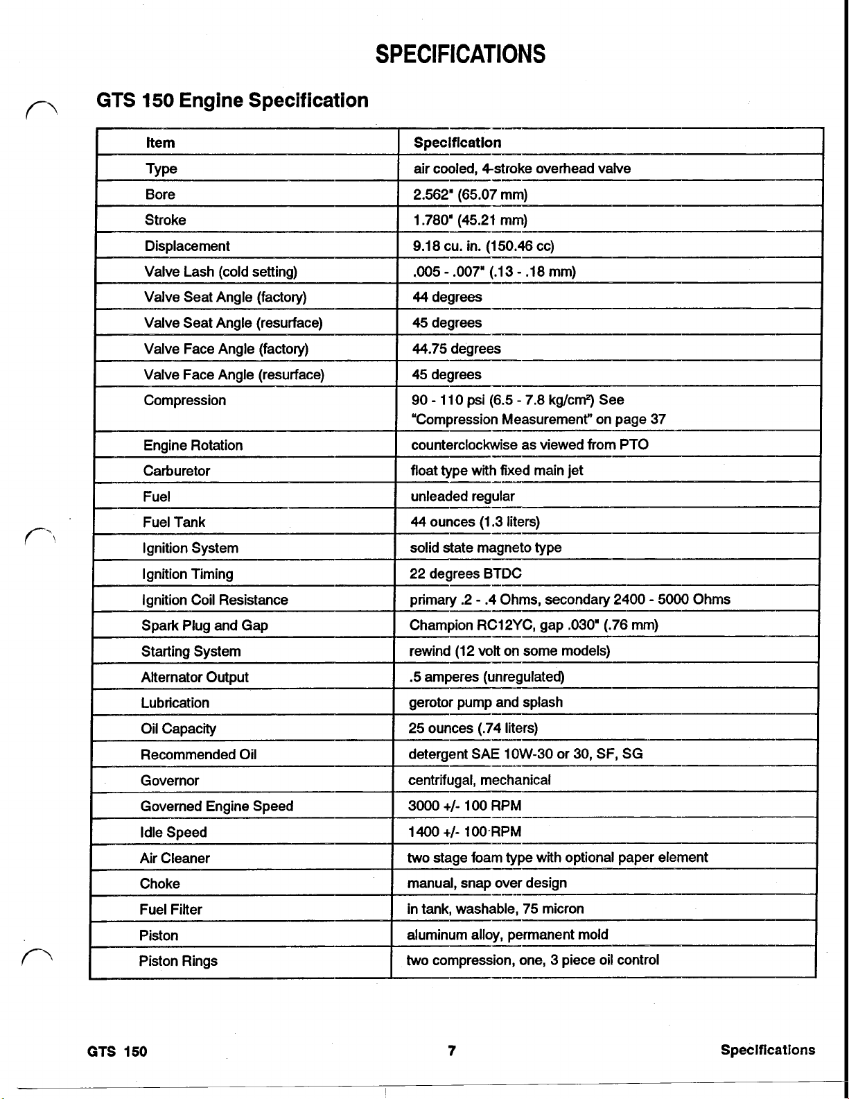
GTS 150 ENGINE SPECIFICATION
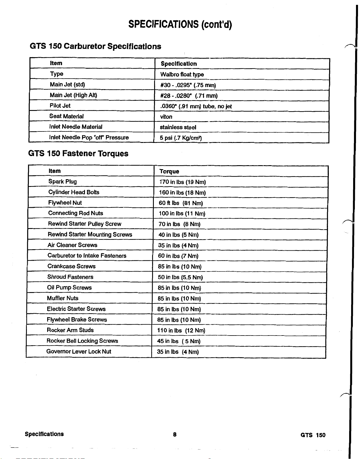
GTS 150 CARBURETOR SPECIFICATIONS
GTS 150 FASTENER TORQUES
TOOL REQUIREMENTS
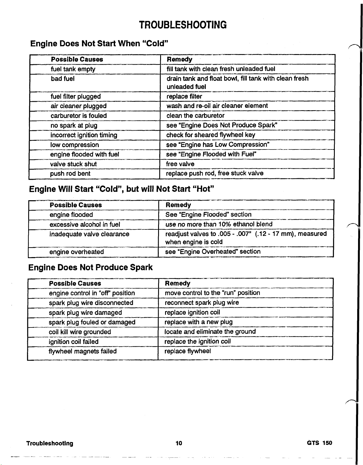
TROUBLESHOOTING
ENGINE DOES NOT START WHEN "COLD"
ENGINE WILL START "COLD", BUT WILL NOT START "HOT"
ENGINE DOES NOT PRODUCE SPARK
ENGINE HAS LOW COMPRESSION
ENGINE FLOODED WITH FUEL
ENGINE LACKS POWER
BENT PUSH ROD
ENGINE SURGING
ENGINE BACK FIRES
ENGINE AFTER FIRES
ENGINE OVERHEATS
ENGINE VIBRATES EXCESSIVELY
ENGINE CRANKSHAFT WILL NOT TURN
ENGINE PRODUCES MECHANICAL KNOCKING SOUND
PRE-IGNITION
ENGINE SMOKES EXCE SSI VE L Y
ENGINE STALLS
SPARK PLUG FOULED
GTS 150 MAINTENANCE
SERVICING AIR CLEANER
REPLACING THE SPARK PLUG
REMOVING GASOLINE FROM THE FUEL TANK
CHANGING CRANKCASE OIL
CARBURETOR - ADJUSTMENT
COMPRESSION - MEASUREMENT
THROTTLE - ADJUSTMENT
CLEAN THE ENGINE AND RECOIL STARTER
CLEAN THE COOLING SYSTEM
PREPARING THE ENGINE FOR STORAGE
Page 2

OHV GTS 150 ENGINE SERVICE MANUAL
Table Of Contents – Page 2 of 4
SECTION I CARBURETOR
CARBURETOR DESCRIPTION
CARBURETOR THEORY AND OPERATION
CARBURETOR - REMOVAL
CARBURETOR - PRESSURE TESTING
CARBURETOR - DISASSEMBLY
CARBURETOR - CLEANING AND SERVICE
CARBURETOR - ASSEMBLY
CARBURETOR - ADJUSTMENT
SECTION 2 FUEL SYSTEM
FUEL TANK - OPERATION
FUEL TANK - REMOVAL
FUEL TANK AND FILTER - CLEANING
FUEL CAP - OPERATION
FUEL CAP - SERVICE
FUEL HOSE - REMOVAL
FUEL HOSE - INSTALLATION
SECTION 3 IGNITION
OPERATION
IGNITION OPERATION - FLYWHEEL
IGNITION OPERATION - IGNITION ARMATURE COIL
IGNITION OPERATION - SPARK PLUG
ARMATURE COIL WIRING - OPERATION
AIR GAP - ADJUSTMENT
IGNITION ARMATURE COIL - REMOVAL
IGNITION ARMATURE COIL - TESTING
IGNITION ARMATURE COIL - INSTALLATION
SECTION 4 REWIND STARTER
REWIND STARTER - OPERATION
REWIND STARTER- DISASSEMBLY
REWIND STARTER - ASSEMBLY
REWIND STARTER - INSTALLATION
Page 3

OHV GTS 150 ENGINE SERVICE MANUAL
Table Of Contents – Page 3 of 4
SECTION 5 ENGINE
ENGINE - OPERATION
INTAKE STROKE
COMPRESSION STROKE
POWER STROKE
EXHAUST STROKE
ENGINE DISASSEMBLY
AIR CLEANER - OPERATION
AIR CLEANER - REMOVAL
REWIND STARTER. OPERATION
REWIND STARTER - REMOVAL
BLOWER SHROUD - REMOVAL
MUFFLER SHROUD - REMOVAL
FLYWHEEL BRAKE - OPERATION (IF INSTALLED)
FLYWHEEL BRAKE - REMOVAL (IF INSTALLED)
FUEL TANK - OPERATION
FUEL TANK - REMOVAL
MUFFLER - OPERATION
MUFFLER - REMOVAL
DIPSTICK AND OIL FILL TUBE - REMOVAL
CARBURETOR - OPERATION
CARBURETOR - REMOVAL
IGNITION COIL - OPERATION
IGNITION COIL - REMOVAL
THROTTLE BRACKET - REMOVAL
ALTERNATOR - OPERATION
ALTERNATOR - REMOVAL (IF INSTALLED)
FLYWHEEL - REMOVAL
ELECTRIC STARTER - OPERATION
ELECTRIC STARTER. REMOVAL (IF INSTALLED)
THROTTLE CONTROL LEVER AND LINK ROD - REMOVAL
VALVE COVER- REMOVAL
HEAD ASSEMBLY - REMOVAL
HEAD - DISASSEMBLY
VALVES AND SEATS - RECONDITIONING
BREATHER - OPERATION
BREATHER - REMOVAL
OIL PUMP - OPERATION
OIL PUMP - REMOVAL
SUMP - REMOVAL
GOVERNOR AND SPLASHER - OPER ATION
GOVERNOR AND SPLASHER - REMOVAL
CAMSHAFT - OPERATION
CAMSHAFT- REMOVAL
COMPRESSION RELEASE - OPERATION
COMPRESSION RELEASE - REMOVAL
CRANKSHAFT- REMOVAL
PISTON AND CONNECTING ROD - OPERATION
Page 4

OHV GTS 150 ENGINE SERVICE MANUAL
Table Of Contents – Page 4 of 4
SECTION 5 ENGINE - continued
PISTON AND CONNECTING ROD - REMOVAL
PISTON RINGS - REMOVAL
PISTON PIN - REMOVAL
GOVERNOR ARM - REMOVAL
ENGINE ASSEMBLY
PISTON PIN - INSTALLATION
PISTON RING - INSTALLATION
PISTON - INSTALLATION
CRANKSHAFT - INSTALLATION
GOVERNOR SHAFT - INSTALLATION
CAM FOLLOWERS - INSTALLATION
CAMSHAFT - INSTALLATION
GOVERNOR/SPLASHER- INSTALLAT ION
SUMP - INSTALLATION
0IL PUMP - INSTALLATION
BREATHER - INSTALLATION
HEAD - ASSEMBLY
PUSH RODS - INSTALLATION
HEAD - INSTALLATION
VALVE CLEARANCE - ADJU ST MENT
VALVE COVER - INSTALLATION
THROTTLE BRACKET - INSTALLATION
GOVERNOR CONTROL LEVER AND LINK ROD - INSTALLATION
CARBURETOR - INSTALLATION
GOVERNOR - ADJUSTMENT
ELECTRIC STARTER - INSTALLATION
FLYWHEEL - INSTALLATION
ALTERNATOR - INSTALLATION
IGNITION ARMATURE COIL - INSTALLATION
FLYWHEEL BRAKE - INSTALLATION (IF REQUIRED)
MUFFLER - INSTALLATION
MUFFLER SHROUD - INSTALLATION
DIPSTICK TUBE - INSTALLATION
FUEL TANK - INSTALLATION
BLOWER SHROUD - INSTALLATION
REWIND STARTER- INSTALLATION
AIR CLEANER - INSTALLATION
SPARK PLUG - INSTALLATION
ACKNOWLEDGEMENT
Page 5
Page 6
PREFACE
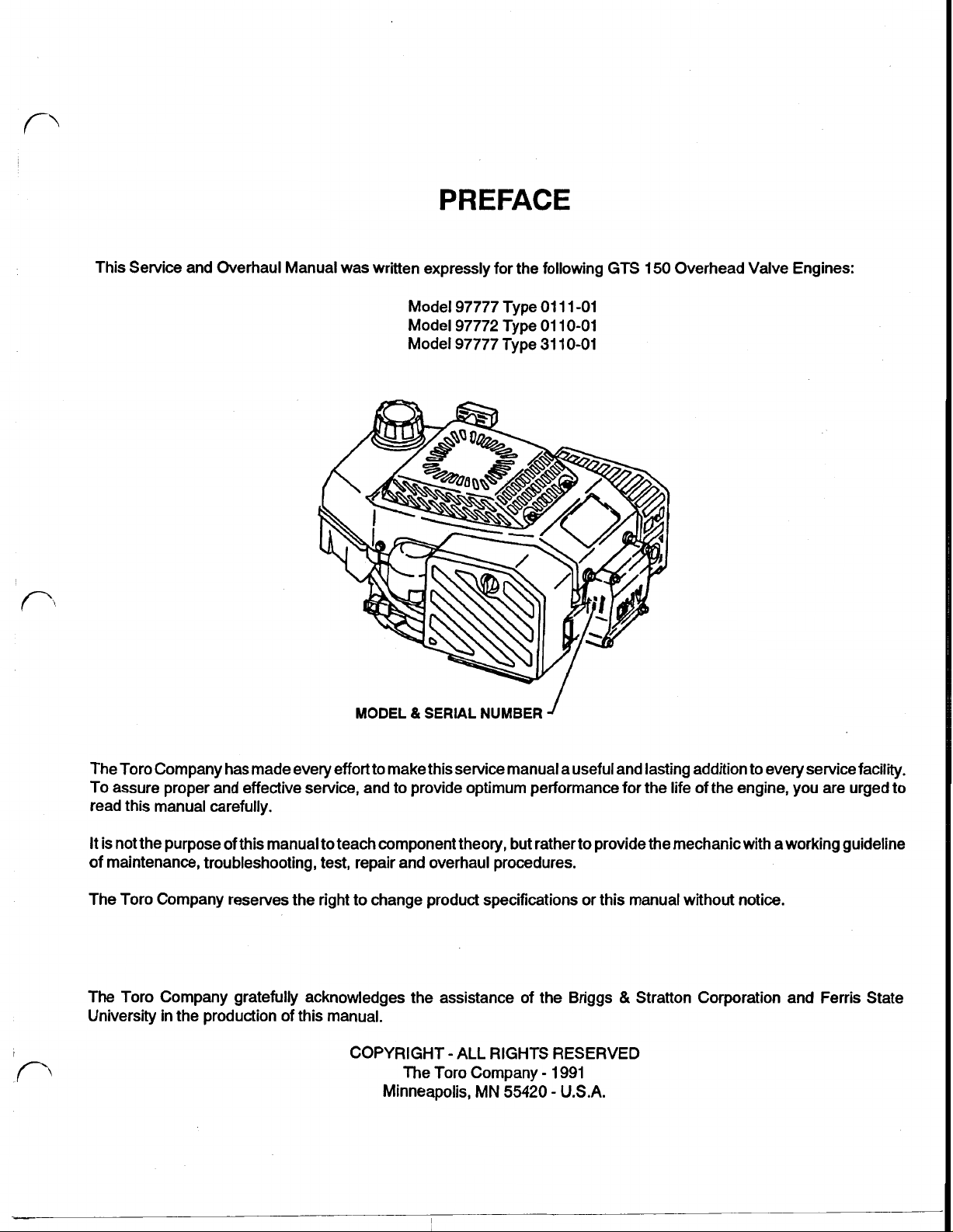
This Service and Overhaul Manual was written expressly for the following GTS
Model 97777 Type
Model 97772 Type
Model 97777 Type
MODEL & SERIAL NUMBER
01
01
31
11
-01
10-01
10-01
150
Overhead Valve Engines:
The Toro Company has made every effort to make this service manual a useful and lasting addition to every service facility.
To assure proper and effective service, and to provide optimum performance for the life of the engine, you are urged to
read this manual carefully.
It is not the purpose of this manual to teach component theory, but rather to provide the mechanic with a working guideline
of maintenance, troubleshooting, test, repair and overhaul procedures.
The Toro Company reserves the right to change product specifications or this manual without notice.
&
The Toro Company gratefully acknowledges the assistance of the Briggs
University in the production of this manual.
I
COPYRIGHT - ALL RIGHTS RESERVED
Minneapolis,
The Toro Company
MN
55420
-
1991
-
U.S.A.
Stratton Corporation and Ferris State
Page 7
Reference Information
TABLE
OF
CONTENTS
Service Procedures
Section
1
Carburetor
Safety Information
Specifications
Tool Requirements
Troubleshooting.,
Maintenance
description
operation
removal
pressure testing
disassembly
cleaning and service
assembly
..................................................................................................................
....................................................................................................................
......................................................................................................................
...................................................................................................................
..............................................................................................
.............................................................................................................
.....................................................................................................
........................................................................................................
...............................................................................................................
..........................................................................................................
................................................................................................................
Page
10
15
19
19
20
21
21
...................................................................................................
21
22
6
7
9
adjustment
Section 2 Fuel System
fuel tank
fuel cap
fuel hose
Section 3 Ignition System
Ignition operation
..................................................................................................................
operation
removal
cleaning
operation
service
removal
installation
flywheel
armature coil
..............................................................................................................
22
...........................................................................................................
............................................................................................................
............................................................................................................
...........................................................................................................
............................................................................................................
........................................................................................................
........................................................................................................
.............................................................................................................
.....................................................................................................
23
23
23
23
23
23
23
25
25
25
Table of Contents
.-
....
-.
GTS
2
...
150
Page 8

Service Procedures (cont’d)
TABLE
OF
CONTENTS
Section
Section
Section
3
Ignition System (cont’d)
spark plug
armature coil wiring
air gap adjustment
removal
testing
installation
4
Rewind Starter
operation
disassembly
assembly
installation
5 Engine
operation
disassembly
..........................................................................................................
......................................................................................................................
........................................................................................................................
..................................................................................................................
....................................................................................................................
....................................................................................................................
..................................................................................................................
....................................................................................................................
Page
....................................................................................................
.....................................................................................................
...............................................................................................................
...............................................................................................................
25
26
26
26
26
26
27
27
28
28
29
30
air cleaner
rewind starter
blower shroud
muffler shroud
flywheel brake
fuel tank
muffler
oil fill tube
carburetor
ignition coil
throttle bracket
alternator
flywheel
electric starter
throttle control lever
head components
valves and seats reconditioning
........................................................................................................
....................................................................................................
...................................................................................................
..................................................................................................
..................................................................................................
...........................................................................................................
..............................................................................................................
..........................................................................................................
.........................................................................................................
........................................................................................................
..................................................................................................
..........................................................................................................
.............................................................................................................
...................................................................................................
...........................................................................................
..............................................................................................
.......................................................................
30
30
30
30
31
31
31
31
32
32
32
33
33
33
34
34
35
GTS
150
breather
............................................................................................................
36
..
3
Table
of
Contents
Page 9

Service Procedures (cont’d)
TABLE
OF
CONTENTS
Section
5 Engine (cont’d)
oil pump
sump
governor and splasher
cam shaft and cam followers
compression release
crankshaft
piston and connecting rod
piston rings and pin
governor arm
assembly
piston pin and rings
piston
crankshaft
governor shaft
cam followers
....................................................................................................
.................................................................................................................
.......................................................................................
.............................................................................
.........................................................................................
.........................................................................................................
.................................................................................
...........................................................................................
.....................................................................................................
...........................................................................................
...............................................................................................................
.........................................................................................................
..................................................................................................
...................................................................................................
Page
36
36
37
37
37
38
38
39
39
40
40
40
41
41
cam
shaft
..........................................................................................................
governor and splasher
sump
.................................................................................................................
oil pump
breather
head
push rods
valves
valve clearance adjustment
throttle bracket
governor control lever
carburetor
governor adjustment
electric starter
flywheel
alternator
ignition armature coil
............................................................................................................
............................................................................................................
..................................................................................................................
.........................................................................................................
...............................................................................................................
..................................................................................................
.........................................................................................................
...................................................................................................
.............................................................................................................
...........................................................................................................
.......................................................................................
...............................................................................
........................................................................................
..........................................................................................
.........................................................................................
41
41
41
42
42
42
42
43
43
43
43
44
44
44
45
45
45
.....
Table
of
Contents
~
4
GTS
150
Page 10

TABLE
OF
CONTENTS
Service Procedures
(cont'd)
flywheel brake
muffler
dipstick tube
fuel tank
blower shroud
rewind starter
air cleaner
spark plug
..........................................................................................
..............................................................................................................
......................................................................................................
...........................................................................................................
...................................................................................................
....................................................................................................
........................................................................................................
.........................................................................................................
Page 45
45
46
46
46
46
47
47
GTS
150
5
Table
of
Contents
Page 11
SAFETY INFORMATION
This safety symbol means
WARNING or CAUTION,
PERSONAL
TION Read the instruction
because
Failure to comply with the
instruction may result in personal injury or
death.
SAFETY
it
has to do wlth safety.
INSTRUC-
SAFETY
This manual is intended as a service and repair
manual only. The safety instructions provided in
this manual are for the troubleshooting and service
of the engine only. The individual Operator's
will contain safety information on the operation of
the complete product powered by the
engine. Operator's manuals with complete operational safety instructions are available through:
The Toro Company
Publications Department
8111
Lyndale Avenue South
MN
Minneapolis,
55430
U.S.A.
Manual
GTS
150
TIPS
Avoid lacerations and amputations ...
Stay clear of all moving parts whenever the engine is
running. Treat
were moving whenever the engine is running or has
the potential to start.
Avoid burns...
Do
not touch the engine while running or shortly after
running.
Avoid fails. ...
Do
not operate the mower on slippery surfaces or
footing is questionable.
Avoid fires and falls...
Wipe up any spilled fuel or
Avoid asphyxiation
Never operate
proper ventilation.
Avoid eye injuries
Wear eye protection when working with springs or
cables and when running engine.
Avoid unexpected starting of engine
Always turn
before attempting any cleaning, adjustment or repair.
all
normally moving parts as
oil.
....
an
engine in a confined area without
....
...
off
key and disconnect spark plug wire
if
they
if
Avoid fires and explosions
Use a container designed for gasoline. Avoid spilling gasoline and never smoke while working around
gasoline.
Avoid accidental misuse of fuel.
Always store fuel
that is designed for gasoline.
Avoid injury due to inferior parts
Use only Toro original parts to insure that important
safety criteria are met.
Avoid injury to bystanders
Always clear the area of bystanders before starting
a
or testing
Avoid injury due to projectiles
Always clear the area to be mowed of sticks, rocks
and other debris that could be picked up and thrown
by the mower.
lawn mower.
in
a properly labeled container
...
..
...
...
...
Safety information
6
GTS
150
Page 12
SPECIFICATIONS
GTS
I
150
Engine Specification
Engine Rotation
Carburetor float type with fixed main jet
Fuel
led, llstroke overhead valve
Measurement on page 37
counterclockwise as viewed from PTO
unleaded regular
I
Recommended Oil
44
ounces (1.3 liters)
solid state magneto type
22 degrees BTDC
primary .2
Champion RC12YC, gap .030" (.76 mm)
rewind (1 2
detergent SAE 1OW-30 or 30, SF,
two
stage foam type with optional paper element
manual, snap over design
in
tank, washable, 75 micron
.4
Ohms, secondary
_-
volt
on some models)
2400
SG
-
5000
Ohms
GTS
Piston aluminum alloy, permanent mold
Piston Rings
150
I
two
compression,
7
one, 3 piece oil control
Specifications
Page 13
SPECIFICATIONS
(cont'd)
GTS
GTS
150
Carburetor Specifications
150
Fastener Torques
Specifications
-
a
GTS
150
Page 14
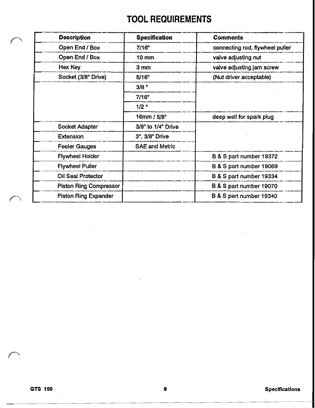
TOOL REQUIREMENTS
Comments
--
_-
----_.I
connecting rod, flywheel puller
valve adjusting
-
valve adjusting
(Nut
driver acceptable)
I-p
deep well for spark plug
_-_s_
B
&
B
6
6
B
&
&
&
&
S
S
S
S
S
-___ti--
11_1--____---
_.____I_____..^_______I-
I
I
nut
_--__
jam
I_--^
____~rmY___
screw
-.
----
part number 19372
part number 19069
part number 19334
part number 19070
part number 19340
~._-
.-
-~
-p_-
-~
--
.I
-
GTS
150
9
Specifications
Page 15
TROUBLESHOOTING
Engine Does Not Start When
Engine Will Start “Cold”, but will Not Start
“Cold”
“Hot”
inadequate valve clearance readjust valves
Engine Does Not Produce Spark
to
.005
-
.007” (.12
-
17 mm), measured
GTS
150
Page 16
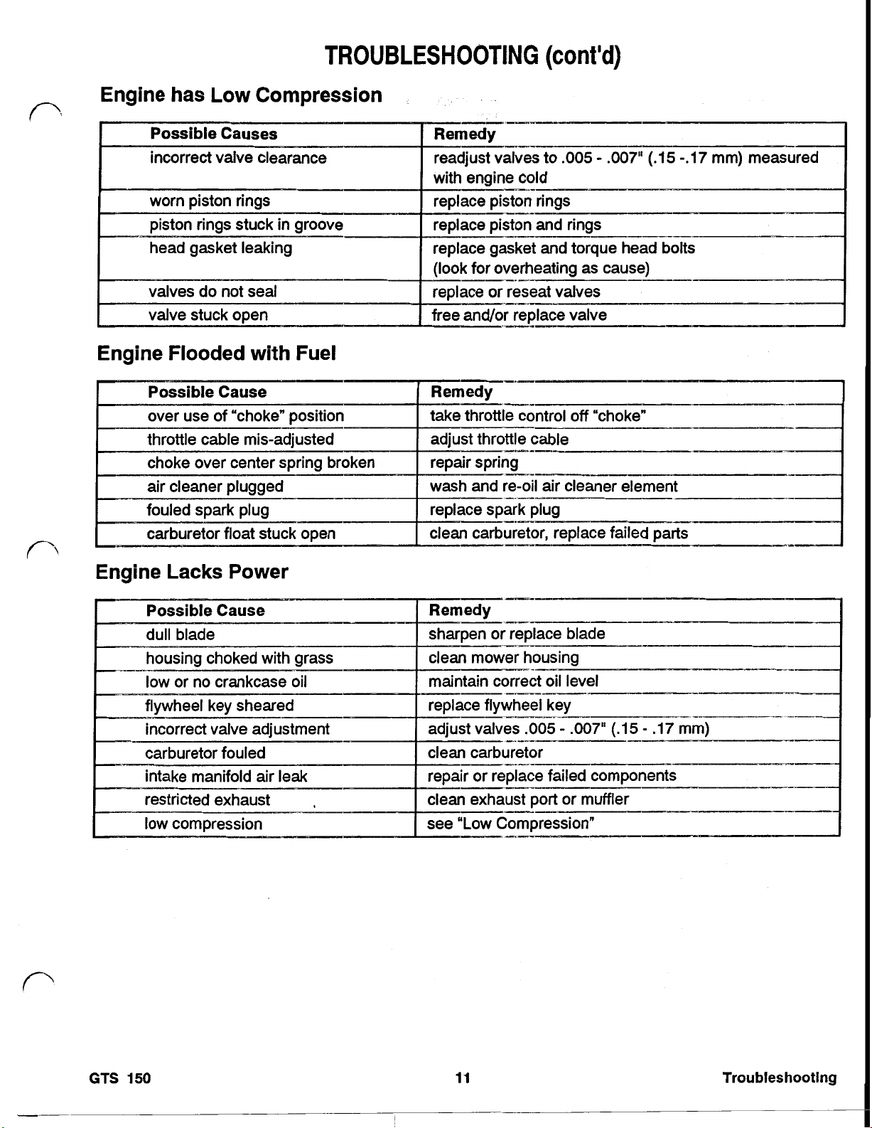
Engine has Low Compression
TROUBLESHOOTING
(cont'd)
incorrect valve clearance readjust valves
Engine Flooded with Fuel
with engine cold
carburetor replace failed parts
to
.005
-
.007" (.15-.17 mm) measured
--
Engine Lacks Power
GTS
150
11
Troubleshooting
Page 17

TROUBLESHOOTING
(cont’d)
Bent Push
Rod
Engine Surging
Engine Back Fires
Engine After Fires
Engine Overheats
Engine Vibrates Excessively
.
out
of
balance-blade
Trouble shooting
12
GTS
150
Page 18

TROUBLESHOOTING
(cont'd)
Engine Crankshaft Will
Not
Turn
Engine Produces Mechanical Knocking Sound
Pre-Ignition
Engine Smokes Excessively
. .
with fresh unleaded regular fuel with no more
--_-
GTS
150
13
Troubleshooting
Page 19

TROUBLESHOOTING
(cont’d)
Engine
Spark
Stalls
Plug Fouled
Page 20

GTS
150
MAINTENANCE
Servicing
Normally, clean the air cleaner after every
hours. More frequent cleaning is required when the mower
is operated in dusty or dirty conditions.
1. Stop the engine, allow
spark plug wire. Remove the key from the key switch
on electric start models.
2.
Rotate the knob securing the air cleaner cover to the
engine until the cover can be removed. Clean the
cover thoroughly. See Figure 1.
Air
Cleaner
25
operating
it
to cool and disconnect the
Replacing the Spark Plug
Use a Champion RC12YC spark plug or equivalent. The
correct air gap is
25
every
1.
operating hours and check its condition.
Stop the engine, allow it to cool and disconnect the
spark plug wire. See Figure
the switch on electric start models.
.030"
(.76mm). Remove the plug after
2.
Remove the key from
Figure
3.
If the outside of the foam element is dirty, remove it
from the air cleaner body and clean it thoroughly. See
Figure
A.
6.
C. Saturate the element with
4.
Reinstall the foam element and air cleaner cover. Do
not operate the engine without the air cleaner element
as extreme engine wear and damage will likely result.
A.
1.
Wash the foam element in a solution of liquid soap
and warm water. Squeeze the element to remove
dirt, but do not twist as the foam may tear. Rinse
thoroughly in clear water.
Dry the element by wrapping
Squeeze the rag and
SAE
1
OW
30
engine oil. Squeeze the element to
remove excess oil and to distribute the oil thor-
A
oughly.
Paper elements are available for use in extremely
dirty conditions. Toro part number 77-901
damp element is desirable.
1
foam
element to dry.
5
teaspoons
it
in
a clean rag.
(25
ml) of
0.
1.
Static Gard
2.
Air Cleaner Code Numbers
3.
Carburetor
4.
Spark
2.
Clean around the spark plug and use a
remove the plug from the cylinder head. Replace a
cracked, fouled, or dirty spark plug. Do not sand blast,
scrape, or clean electrodes as engine damage could
result from grit entering the cylinder.
3.
Set the air gap at
the correctly gapped spark plug and gasket seal.
Tighten the plug to
Plug
.030"
14
5.
Model,
6.
Muffler
7.
Muffler Guard
(0.76 mm) , See Figure
ft Ibs (1 9 N-m)
(.76MM)
Type
518"
and
socket to
3.
Install
1
GTS
150
15
Figure
3
Maintenance
Page 21

Removing Gasoline from the Fuel Tank
1.
Stop the engine, allow it to cool and disconnect the
spark plug wire. Remove the key switch on electric
start models.
2.
Remove the cap from the fuel tank and use a pump
type siphon to transfer fuel into a clean gas can
container designed to hold gasoline. Note: this is the
only fuel removal procedure that should be used for
general maintenance.
Changing Crankcase Oil
2
Change the oil after the first
25
every
more contaminants than cold oil, run the engine for a
minute period before draining the oil.
1.
hours. Since warm oil will drain better and carry
Stop the engine, allow it to cool and disconnect the
spark plug wire. See Figure
operating hours and after
4.
or
5
5.
When the oil is drained, return the mower to its upright
position and add fresh oil to the engine. Refer to
"Filling the Crankcase with Oil" on pagexx. The crank-
25
oz
(.74
case capacity is
the crankcase may retain a small amount of oil, reducing the amount required to bring the oil level back to
normal.
Carburetor -Adjustment
1
.
Turn the idle mixture screw clockwise until
NOT FORCE.
2.
Turn the idle mixture screw counterclockwise
turns. This will permit the engine to start and final
adjustment can be made with the engine running.
3.
Start the engine and allow
4.
While the engine is running, move the speed control
lever to the fast position until the hole "A"
lever aligns with the hole
6.
See Figure
the holes
Use a
in
position.
liters). When changing oil,
it
seats.
it
to warm up.
in
the throttle
in
the throttle control bracket.
1/8"
(3
mm) diameter pin to hold
DO
1-1/2
Figure
2.
Remove the' gasoline from the fuel tank: refer to
"Removing Gasoline" on page
3.
Remove the dipstick from the oil
drain pan next to the left side of the mower.
4.
Tip the mower on its left side, allowing the oil to drain
into the drain pan. See Figure
4
23.
fill
tube and place a
5.
ALIGNED
HOLES
'A'
Figure
5.
Adjust the high speed screw on the throttle control
a
3000,
1/8"
(3
bracket to obtain
6.
Remove the pin and move the speed control lever to
the slow or idle position, until hole
control lever aligns with the hole
bracket.
holes in alignment.
7.
Adjust the idle speed stop screw to
Figure
Use
7.
6
100
RPM.
“B”
in the throttle
in
the throttle control
mm) diameter pin to hold the
1700,
100.
See
Figure
5
16
Page 22

IDLE
TOP
SPEED
MIXTURE
NO
LOAD
SCREW
1.
Stop the engine, allow
it
to cool and disconnect
spark plug wire. Remove the key on electric
models.
2.
Move the throttle control to the "Fast" position.
3.
Loosen the cable clamp screw until the throttle cable
sheath can slide
4.
Move the throttle cable left or right until holes in the
in
its
clamp.
throttle lever and throttle bracket align. See Figure
THROTTLE
BRACKET
the
start
8
Figure
7
8. Turn the idle mixture screw slowly, clockwise (lean
mixture) until the speed just begins to slow down.
Then, turn the idle mixture screw slowly counterclock-
in
wise (rich mixture) until the engine increases
speed
and then just starts to slow down. Turn the screw to a
if
midpoint position between rich and lean. Note:
the
speed exceeds 1900 RPM during this adjustment,
7
repeat step
and 8. If the engine does not accelerate
properly, re-adjust the idle mixture screw approximately 1/8 of a turn counterclockwise to richen the
mixture.
9. Remove the aligning pin and re-adjust the idle speed
stop screw to 1400 100 RPM.
IO.
Re-check the high speed setting.
-
Compression
Measurement
Engine compression can vary depending on the technique
and compression gauge used to make the measurement.
5.
6.
7.
The compression values given in the specification section
are a reference point only. We recommend the individual
8. Connect the spark plug wire.
dealer establish compression values based on new product using his or her own technique and compression
Clean the Engine and Recoil Starter
gauge.
Accumulated yard debris and dirt can cause overheating
1. Remove the spark plug and install a compression
gauge that threads into the spark plug opening.
2.
Pull the starter rope rapidly to achieve a momentary
500
engine speed of over
RPM. This will cause the
and malfunction of control linkages. Before every mowing
the muffler area, throttle linkage and air intake screens
should be cleaned of debris.
1. Stop the engine, allow it to cool and disconnect the
compression release mechanism to allow the intake
valve to completely close.
3.
Pull the starter rope repeatedly until there is no further
2.
rise in the compression value.
Throttle -Adjustment
Throttle control adjustment may be required
if
the engine
3.
does not start, stop or run at the correct speed. Whenever
a new throttle control cable is installed, the throttle must be
adjusted.
HOLES
'A'
CABLE
CLAMP
SCREW
Insert a
1/8"
CABLE
(3
mm) pin
Figure
8
in
the aligned holes to hold the
throttle lever in position.
Pull the throttle cable slightly to remove any slack and
tighten the cable clamp screw to lock the adjustmen
in
place.
Remove the 1/8"
control back to the
(3
mm) pin and bring the throttle
off
position.
spark plug wire. Remove the key on electric starl
models.
Remove dirt and debris with a cloth, brush or
pressure
(30
psi,
200
kPa or less) air. When using
compressed air be sure to wear safety glasses
low
to
prevent eye injury from airborne debris.
A forceful stream of water is not recommended
as
it
could cause contamination of the fuel system.
GTS
150
17
Malntenance
Page 23

Clean the Cooling
Every25 hours, or every cutting season, the engine blower
housing must be removed and the cooling fins cleaned.
Failure to clean the cooling system may lead to engine
overheating and severe engine damage.
1.
Stop the engine, allow
spark plug wire. Remove the key
models.
2. Remove the four
retain the blower housing to the engine.
3.
Remove the gas cap and lift the blower housing and
recoil starter assembly away from the engine to expose the cooling fins. Replace the gas cap.
4. Remove dirt and debris with a cloth, brush or low
pressure,
compressed air be sure to wear safety glasses to
prevent eye injury from airborne debris. See Figure
System
it
to cool and disconnect the
on
electric start
3/8"
hex, washer head screws that
30
psi (200 kPa) or less, air. When using
9.
Fuel can be left
as Toro's Stabilizer/Conditioner is added to the gasoline
and
Toro's Stabilizer/Conditioner is petroleum distillate based.
The Toro Company does not recommend stabilizers with
-an alcohol base, such
alcohol.
Under normal conditions, all fuel additives remain effective
in
1.
2.
3.
4.
in
the fuel tank only
run
through the engine before storage.
as
ethanol, methanol or isopropyl
fuel for
6-8
months.
Remove the spark plug and pour
(30
ml) of
SAE
30
oil into the spark plug hole
cylinder. Pull the starter rope slowly to coat the inside
of the cylinder. Install the spark plug and tighten
to 14 ftIb (19Nm). Do not connect the spark plug wire.
Clean dirt and chaff from the cylinder, cylinder head
fins, and blower housing. Also remove grass clippings,
dirt and grime from the external parts of the engine,
shrouding and top of the mower housing.
Clean the air cleaner: refer to the Maintenance Sec-
tion on Servicing the Air Cleaner on page
Change the engine oil: refer to the Maintenance
Section on Changing the Engine Oil on page 16.
if
a fuel additive such
two
tablespoons
in
15.
the
5.
Tighten all nuts,
6.
Store the engine
engine to keep
W
Figure
5.
Remove the gas cap and install the blower housing.
Replace the gas cap. Install the four
head screws that retain the blower housing. Tighten
50
the screws to
Preparing the Engine for Storage
For long termstorage, either remove gasoline
tank and carburetor as described on page 16 or add a fuel
stabilizer to the gasoline. If the gasoline has been removed
from the fuel tank, start the engine and allow it to idle until
all the fuel is consumed and the engine stops. Repeat the
starting procedure
line is removed from the engine. If gasoline is not removed
from the carburetor
deposits will form and cause starting problems and/or poor
engine operation.
in Ibs (5.6 N-m)
two
more times to assure all the gaso-
in
this manner, gum-like varnish
9
3/8"
hex, washer
from
the
fuel
bolts
and fasteners.
in
a clean, dry place. Cover the
it
clean and protected.
18
GTS
150
Page 24

SECTION 1 CARBURETOR
Carburetor Description
The carburetor used on the
GTS
150 is a dual circuit (pilot
and main), float bowl design with fixed main jet, fixed
nonremovable pilot jet and an adjustable pilot circuit
mixture screw. The carburetor is fitted with a standard
number
30
(.0295") main jet.
A
high attitude main jet
number 28 (.0280") is also available. The carburetor is
fitted with a stainless steel inlet needle and a replaceable
inlet seat. The throttle and choke shaft are equipped with
dust seals.
Carburetor
Theory
The carburetor receives fuel from the tank and mixes
and Operation
it
with air in the right proportions to provide a highly combustible mixture to the engine.
As
the piston moves down on the intake stroke, a partial
vacuum is created within the cylinder, causing the greater
atmospheric pressure to force air to flow through the
carburetor into the cylinder. The velocity of the air
creases as
it
flows through the carburetor venturi and the
air pressure is reduced at this point to less than atmospheric pressure. The differences of pressure in the venturi
of the carburetor causes atmospheric pressure to push
raw fuel from the float bowl into the air stream where it
breaks up into a fine spray, or becomes atomized, and
mixes with the air stream. See Figure 10.
in-
Fuel atomization becomes more efficient due to heat, once
the engine has reached normal operating temperature.
a result, the engine does not require the rich mixture it did
for starting and the choke plate must be moved to the open
position. The engine speed is now regulated by the throttle
plate. In no load condition, a small portion of the fuel may
be drawn from the main discharge tube, however the
primary fuel supply is drawn from the pilot circuit. Air
passing through the pilot jet from the pilot air fitting draws
fuel
pre-mixes with the incoming air and is discharged into the
VENTURI
carburetor bore where the fuel becomes atomized. See
Figure 12.
PILOT
SYSTEM
COLD START
Figure
out
of the pilot jet orifice from the float bowl. This fuel
11
As
--
CARBURETOR
BORE
TO
FLOAT BOWL
When starting the engine, an extra rich mixture is required.
The choke plate is closed by the operator to provide an
approximate 8:l (approximately six times richer than
normal) ratio of fuel to air for this rich mixture. Closing the
choke plate further reduces the air pressure area in the
venturi to increase the fuel drawn into the carburetor bore.
In this condition, fuel is drawn from the float bowl through
the pilot system ports as well as the main discharge tube
to achieve the proper starting mixture. See Figure 11.
GTS
150
ENGINE
19
''LOT
I
Figure
PILOT
12
JET
I
PILOT
AIR
FITTING
Carburetor
Page 25

As the throttle plate is opened to compensate for engine
load, the main discharge tube becomes the main source of
fuel. Opening the' throttle plate increases the flow of air
through the venturi and strengthens the low pressure area
at the main discharge tube. Fuel discharge increases at
the main discharge tube as it decreases from the pilot
system. Air is drawn from the air correction jet, through
holes along the length of the main discharge tube. This
it
pre-mixes air with the fuel before
bore for more efficient atomizing of the fuel. See Figure
SYSTEM
enters the carburetor
13.
3.
Disconnect the choke over-center spring. Note the
position of the spring for correct assembly. See
Figure
15.
Figure
Carburetor
1.
Remove the fuel from the tank as described in the
Maintenance Section on page
2.
Remove the three
screws retaining the air cleaner to the carburetor.
Take care not to lose the cork gasket that seals
between the air cleaner body and the carburetor. See
Figure
Removal
5/16"
14.
13
16.
hex, washer head shoulder
Figure
4.
Remove the
retain the carburetor, the insulator gasket, and engine
block. See Figure
two
3/8"
16.
15
hex, washer head screws that
Figure
14
20
Figure
5.
Have a rag ready to absorb a small amount of spilled
gasoline. Pull the carburetor away from the engine.
Twist
the carburetor to unhook the carburetor from the
governor link rod. As the carburetor is tilted, fuel that
is
in the fuel bowl may leak
6.
Hold the carburetor over a drain pan and use a
wrench to loosen the bowl nut. Allow the remaining
in
the bowl to drain into the pan. Tighten the bowl
fuel
nut.
16
out
the bowl vent tube.
GTS
1/2”
150
Page 26

Carburetor
1.
Turn the carburetor upside down.
2.
Connect a pressure tester to the inlet fitting on the
carburetor. See Figure
3.
Pump the pressure to the inlet needle "pop
sure,
4.
The inlet needle should
down to zero, the inlet needle is not seating indicating
that carburetor service is required.
Carburetor Disassembly
5
psi
Pressure.
Figure
(.3
kglcm
Testing
17.
17
2).
seal.
off
If the pressure leaks
pres-
IDLE
STOP
SCREW
IDLE
MIXTURE
SCREW
.-
Figure
5.
Thethrottle plate is retained with one screw. When the
plate is removed the throttle shaft may be withdrawn
from the body of the carburetor.
6.
The choke plate is retained in a slot
an
with
pulling
shaft may then be removed from the body of the
carburetor.
7.
If the carburetor vent passage is open
sary to remove the welch plug that covers the vent
opening
area that does not have a filter screen or other
cleanable device.
interference
it
out
of the slot with a pair
in
the bowl
fit.
19
in
the choke shaft
The plate may be removed by
of
pliers. The choke
it
is not neces-
of
the carburetor. This is a vent
1.
Remove the bowl nut, bowl and gasket.
2.
Use a
9/16"
wrench to remove the main jet and float
stop disc. See Figure
3.
Remove the float hinge pin, float and inlet needle.
4.
Remove the idle mixture screw and spring and the idle
stop screw and spring. See Figure
18.
Figure
18
19.
8.
Remove the pilot circuit welch plug from the side of the
carburetor. Pierce the plug with a small chisel or
pointed device and pry the plug out of the body of the
carburetor.
9.
The viton, fuel inlet seat may be removed by pulling the
of
seat out
crochet hook.
Carburetor Cleaning and
I.
CAUTION:
use with chemicals and wear eye protection when
working with carburetor cleaning materials. Work only
in
well ventilated areas free from sparks or flames.
Make sure you follow all manufacturers recommendations on the use of their cleaning products.
2.
The carburetor
in carburetor cleaner, however; after the soak, each
passage and component in the carburetor should be
washed with a pressurized carburetor cleaning agent.
Soak tanks may not
cleaner will remove any residue.
3.
Direct the pressurized cleaner through all openings
and passages
or air flow.
the body
of
the carburetor with a number
Service
Wear gloves that are suitable for
body
and components may be soaked
be
clean and the pressurized
in
the opposite direction of normal fuel
5
GTS
150
21
Carburetor
Page 27

4.
Use extreme care with mechanical cleaning devices:
i.e. wires, probes, tip cleaners, etc. Mechanical cleaning may damage or enlarge critically sized carburetor
components and passages.
Carburetor - Assembly
1,
Install a new welch plug in the pilot circuit opening on
1/8”
(3
the body of the carburetor. Use a
punch to dimple and seal the welch plug
the carburetor.
2.
Install the throttle shaft dust seal and throttle shaft in
the body of the carburetor.
3.
Use red, number
screw and install the throttle plate. Allow the specified
amount of time for the Loctite to cure before operating
the engine.
4.
Place a dust seal on the choke shaft and insert the
choke shaft in the body of the carburetor.
5.
While looking at the choke end of the carburetor,
position the choke shaft with the over-center spring
slot toward the right side
6.
Insert the choke plate
slot of the choke shaft. The choke should fully close
90
with a
degree clockwise turn of the shaft.
271
Loctite
(R)
on the throttle plate
of
the carburetor.
so
the plate is captured in the
mm) pin
in
the body of
10.
Install the needle on the float. Put the float and needle
in
position and insert the hinge pin.
1I.
Install the float stop disc and
12.
Install the bowl gasket and the
13.
Install the bowl nut.
the
fuel
main jet.
bowl.
Carburetor -Adjustment
See “Carburetor - Adjustment"
on page
16.
in
the Maintenance Section
7.
Install the idle stop screw. Adjustment of the screw
should be performed when the engine is running. Idle
1700
speed should beset to
carburetor adjustment procedure.
8.
Install the idle mixture screw; nominally set at
1-1/2 turns open. See Figure
IDLE
MIXTURE
SCREW
RPM. See page
20.
16
for the
1
to
9.
Install a new viton seat. Insert the seat with a
mm) pin punch. The flat end of the inlet needlewill also
in
work to push the seat
damage the point end of the needle.
place. Take care not to
Carburetor
1/8"
(3
22
GTS
150
Page 28

SECTION
2
FUEL
SYSTEM
FUEL
Fuel lank Operation
The GTS150 uses a 1.6 quart (1.5 liters) plastic fuel tank
with a non-replaceable75micron in-tankfilterscreen. The
filter is welded in the bottom of the tank over a sediment
reservoir. The tank is mounted above the level of the
carburetor and uses gravity to supply fuel through a .25'
I.D. (6.35 mm) rubber hose to the carburetor. The fuel tank
is vented through an opening in the fuel cap. The fuel hose
is retained to the tank and the carburetor with spring type
hose clamps. The fuel opening on the tank is 1.75" (45
mm) in diameter and is opposite the fuel outlet helping to
prevent damage to the filter screen by funnels and gasoline filler spouts. The placement of the cap also prevents
interference with the starting rope
Fuel lank Removal
1. Crimp the fuel hose with a pair of locking pliers to
2. Remove the hose clamp on the carburetor end of the
3.
4. Remove the four 3/8" hex, washer head screws that
5. Remove the gasoline tank cap and remove the blower
6.
TANK
in
Zone
Start
applications.
prevent fuel flow.
hose.
CAUTION:
in a container designed for gasoline and never smoke
while working around gasoline. Release the clamping
pliers and drain the fuel into a container designed to
receive gasoline.
retain the blower housing to the engine. It is not
necessary to remove the recoil starter.
housing.
Remove the
retain the fuel tank to the fuel tank bracket.
Avoid fire and explosion. Store fuel
two
3/8" hex, washer head screws that
into the tank from an opening in the cap to allow gravity to
feed fuel to the carburetor.
Fuel Cap Service
1.
The fuel cap may not
vent opening on the cap and inner sealing disc should
be kept free of debris.
2. Theventilating ability of the cap may be tested by filling
the cap with water and observing the flow
of the vent opening
the
not drain,
3.
If the cap will not vent properly,
Fuel Hose - Removal
1.
CAUTION:
fuel
in
smoke while working around gasoline.
2. Remove the air cleaner cover and foam element.
3.
Remove the three 5/16" hex, washer head shoulder
screws that retain the air cleaner body to the engine.
4. Pull the air cleaner body away from the engine. Take
care not to lose the cork gasket between the air
cleaner and the carburetor. Take note of the position
of the breather hose on the back of the air cleaner and
the location of its' connection to the breathervent tube.
5.
Disconnect the fuel hose from the carburetor by
squeezing the spring type hose clamp with a pair of
pliers.
6.
Drain the fuel into a container designed for gasoline.
7.
Remove the fuel hose from the fitting on the bottom of
the gasoline tank.
Fuel Hose - Installation
vent
a container designed for gasoline and never
be
disassembled, however, the
of
water out
in
the side of the cap. If water does
opening may
Avoid fire and explosions. Store
be
plugged
it
should be replaced.
or
restricted
Fuel lank and Filter Cleanlng
1. Wash the tank in clean solvent designed for cleaning
engine parts.
2. Back wash the filter screen by directing cleaning
vent, under pressure, through the sediment reservoir
and screen, opposite fuel flow direction.
3. Wash the tank again with clean solvent.
4. Clean or replace the fuel hose.
Fuel Cap Operation
The fuel cap is a three piece design with an inner sealing
disc that is vented to a baffle assembly in the body of the
cap. The baffle assembly acts to allow expansion in the
loss
tank without
GTS150
of fuel. Atmospheric pressure is allowed
sol-
23
Make certain the fuel hose is clean. Even
1.
hose is new, run clean solvent through the inside of the
hose prior to installation.
a
Install
2.
end of the fuel hose. Install the hose on the outlet pipe
of the fuel tank. Secure the fuel hose with the hose
clamp.
Install the other end of the fuel hose to the inlet pipe on
3.
the carburetor and secure it with the remaining hose
clamp.
Install the body of the air cleaner.
4.
IMPORTANT:
on the back of the air cleaner body mates with the
spring type hose clamp
Take care that the breather vent hose
2"
(5 cm) from each
Fuel
if
the fuel
System
Page 29

breather vent tube. Leakage
to enter the air cleaner on the carburetor side
filter element.
5.
Make sure the cork gasket is between the air cleaner
body and the carburetor. Install the three
washer head shoulder screws.
6.
Make sure the air cleaner element is properly cleaned
and oiled, see Maintenance Section on page
install the element.
7.
Install the air cleaner cover and tighten the thumb
screw.
in
this area will allow dirt
5/16"
of
15
the
hex,
and
GTS150
Page 30

operation
SECTION 3 IGNITION
The firing of the spark plug at the proper time
culmination of a number of components working together.
These components on the GTS 150 are:
Flywheel
Ignition armature coil
Spark plug
Armature coil wiring
The following describes the function of each of the above
components.
Ignition
The flywheel is connected directly to the crankshaft and
turns at the same speed
the flywheel are three magnets. These magnets rotate
past the coil to generate electricity.
Imbedded in the opposite side of the flywheel are steel
counterweights which offset the weight of the three magnets. These counterweights are not magnetic.
Ignition Operation
The ignition armature coil is actually a transformer.
positioned close to the flywheel to allow the magnetic field
of the flywheel magnets to cut through the wire coils of the
armature coil to generate electricity. See Figure 21.
Operation - Flywheel
as
the crankshaft. Imbedded in
-
Ignition
Armature Coil
IGNITION
COIL
is
It
the
is
the voltage at point
tor
to flow through the collector, emitter circuit of TR2 than it
With the base current for TRI diverted, TR1 turns
opening the armature coil primary circuit. Remember, the
current flowing through resistor
small and can not support the magnetic field created
primary winding. When the circuit through TR1 opens, the
magneticfield in the primary winding collapses, generating
an extremely high voltage in the secondary winding,
enough voltage to cause a spark at the spark plug.
Figure
Lowvoltage is produced in the primary coil of the armature
coil which causes a very small current to flow through
"R"
resistor
current will cause the transistor to "turn on" creating a low
resistance path through the collector, emitter circuit of the
transistor
As the magnets continue to cut through the coils of the
primary winding the primary voltage will increase.
voltage also develops across the voltage divider network
created by resistors R1
resistance path for the base current flowing through resis-
"R".
is
through the base, emitter circuit of TR1.
to the base of transistor TR1. This small base
as
shown by the dotted line.
,
R2. At a precisely timed moment,
"A"
In fact, when this occurs,
22
This
turns TR2 "on" creating a low
it
is easier for the current
"off,
"R"
and TR2 is extremely
in
the
Figure
Complete operation of the ignition circuit is described with
reference to Figure 22.
GTS
150
21
Ignition Operation Spark Plug
The spark plug is used to ignite the air-fuel mixture by
producing a spark just before the piston reaches top dead
as
center. A spark plug is typically constructed
Figure
23.
25
shown
Ignition
in
Page 31

INSULATOR
5.
Tighten the
the armature coil to
6.
Remove the gas cap and replace the blower shroud.
The blower shroud fasteners are tightened to
(5.6Nm).
7.
Install the gas cap.
Ignition Armature Coil Removal
1.
Remove the gas cap.
5/16"
hex, washer head screws retaining
45
in
Ibs
(5Nm).
50
in
Ibs
E
a
Figure
There are two critical areas important to proper spark plug
function. The first is that the electrodes are properly
gapped and are clean. This ensures that a strong spark will
it
be present and that
gap or fouling can delay firing enough to cause a
power or stalling. Correct gap is
The other important area is the insulator. The insulator
prevents arcing from taking place in another area of the
plug, away from the electrodes. Because of the extremely
high voltage present, even a slight crack or fouling of the
head insulator can result in arcing and a malfunction of the
Plug-
Armature Coil Wiring - Operation
The armature coil has two external wires. One wire is the
high voltage spark plug wire and the other wire is the
primary grounding or engine kill wire. The free end of the
kill wire is terminated at the throttle bracket kill terminal.
There are two ground terminals that connect to the frame
of the armature coil and through the armature coil frame to
the block of the engine.
occurs at the proper time. Excessive
23
.030" (.76
CHAMPION
RC12YC
.OW"
(.76
mm).
mm)
loss
of
4.
5.
6.
Ignition Armature Coil Testing
Use an approved tester to test armature coils. Coil specifications are supplied by the tester manufacturer or can be
found in Briggs and Stratton form
Book
1.
2.
CAUTION:
gas tank. Do not smoke or allow open flames around
gasoline. Gasoline fumes are explosive.
2.
Remove the four
retain the blower housing.
3.
Remove the blower housing and replace the gas cap
on the fuel tank.
Disconnect the armature coil secondary ground wire
(igniton kill wire) from the grounding terminal on the
throttle control bracket.
Unplug the spark plug wire.
Remove the
retain the armature coil. The armature coil may now be
removed from the engine.
for Testing Briggs Stratton Ignition Coils."
The primary coil should have
tance. The secondary coil should have
ohms of resistance.
Primary resistance is measured between the kill wire
and ground. Because the primary resistance
small the resistance measurement will more realistically be used for disclosing either short circuits or,
more likely, open circuits
two
extreme care
3/8"
hex, washer head screws that
5/16"
hex, washer head screws that
in
if
there is fuel in the
MS-7862,
.2
to
.4
ohms of resis-
2400
the primary winding.
"Instruction
to
5000
is
so
Air Gap Adjustment
1.
Remove the gas cap.
Use extreme care if there is fuel in the
Do
gas tank.
gasoline. Gasoline fumes are explosive.
2.
Remove the four
retain the blower housing.
3.
Remove the blower housing and replace the gas cap
on the fuel tank.
4.
Loosen the two screws that retain the ignition armature coil. Use a feeler gauge to set the air gap between
the flywheel and ignition armature coil to
(.20
-
.30
Ignition
not smoke or allow open flames around
3/8"
hex, washer head screws that
.008
-
.012."
mm)
3.
Secondary resistance is measured between the spark
plug wire and ground.
Ignition Armature Coil Installation
I.
26
Lightly tighten the
armature coil. Use a feeler gauge to set the air gap
between the flywheel and ignition armature coil to
-
.012."
(.20
2.
Tighten the
the armature coil to
3.
Remove the gas cap and install the blower shroud.
The blower shroud fasteners are tightened to
(5.6Nm).
4.
Install the gas cap.
two
screws that retain the ignition
.30
mm)
5/16"
hex, washer head screws retaining
45
in
.~
Ibs (5Nm).
50
GTS
.008
in
Ibs
150
Page 32

SECTION
4
REWIND STARTER
Rewind Starter Operation
The rewind starter operates through a retainer/friction disc
that causes
center of the rewind starter and engage the inside of the
starter cup on the flywheel. The engagement dogs move
into contact with the starter cup when the rewind rope is
pulled. When the engine starts, the speed of the engine
exceeds the speed of the rewind starter and forces the
starter dogs back into the center of the rewind mechanism,
disengaging them from the starter cup.
Rewind Starter Disassembly
1.
Remove the four
retain the rewind starter assembly to the engine.
2.
Remove the alignment pin from the Phillips head
screw in the center
Figure
24.
two
engagement dogs to extend from the
5/16"
hex, washer head screws that
of
the rewind mechanism. See
4.
Remove the
of the positioning of the springsfor correct installation.
See Figure
5.
Completely extend the rewind rope and hold the reel
in
place. Untie the knot
the rope and slowly allow the reel to unwind to a
relaxed state.
two
ratchet dogs and springs. Take note
26.
Figure
26
in
the end of the rope, withdraw
Figure
3.
Remove the Phillips head screw from the center of the
rewind mechanism and
starter. See Figure
25.
24
lift
the friction plate from the
6.
Remove the reel from the rewind housing. The rewind
spring is captured
suddenly released.
able. If the spring has failed, an entire spring and reel
assembly must
in
the reel and will not fall
The
rewind spring is not service-
be
used for repair. See Figure
Figure
27
out
or
27.
be
GTS
150
Figure
25
27
Rewind
Starter
Page 33

Rewind Starter Assembly
1.
Lubricate the center post of the rewind starter with a
small amount of general purpose grease.
2.
Place the reel assembly on the center post
rewind starter and turn the reel counterclockwise until
the hook on the reel spring engages the spring retainer
on the center post of the starter. See Figure
of
28.
the
4.
Install the friction disc retainer and retaining screw.
See Figure
30.
SCREW
Figure
3.
Install the dog springs and the brake spring as shown
in Figure
29.
Figure
28
29
I
5.
Drive the aligning roll pin into the center of the retaining screw and slide the plastic sleeve over the pin. See
Figure
Rewind Starter Installation
1.
Install the rewind starter on the blower housing, cen-
tering the aligning pin in the opening
crankshaft.
31.
Figure
Figure
30
31
in
the end of the
Rewind Starter
28
2.
Install the four
screws and tighten to
5/16"
hex, washer head retaining
40
in
Ibs
(4.5Nm).
GTS150
Page 34

SECTION 5 ENGINE
Engine - Operation
Intake Stroke
The GTS
The running engine begins with the first of four strokes
being the intake stroke. The piston moves from Top Dead
Center (TDC) to Bottom Dead Center (BDC) with the
intake valve opening
as the piston reaches BDC. While the piston is moving
toward BDC with the intake valve open, a partial vacuum
is created in the cylinder. Air and fuel will enter the cylinder
under atmospheric pressure as long as the intake valve is
open and the piston is moving toward BDC. See Figure
150
is a four stoke cycle, over head valve engine.
as
the piston leaves TDC and closing
32.
Power Stroke
When the piston comes close to TDC the mixture is ignited
by the spark plug and the third stroke begins. The expand-
ing combustion gases push the piston down
creating the power stroke, both the intake and exhaust
valves are still closed
at
this time. See Figure
Figure
34
in
the cylinder
34.
Figure
Compression Stroke
The second stroke (compression) begins
leaves BDC and moves toward TDC. Both the intake and
exhaust valves are closed at this time. As the piston
moves, the air/fuel mixture is compressed
See Figure 33.
32
as
the piston
in
the cylinder.
Exhaust Stroke
The fourth stroke (exhaust) begins as the piston reached
As
BDC and the exhaust valve opens.
TDC
toward
engine. See Figure 35.
the piston forces the exhaust gases from the
the piston moves
GTS
150
Figure
33
29
Figure
35
Engine
Page 35

Engine Dissassembly
Rewlnd Starter Operation
See Section 4 Rewind Starter on page
Air Cleaner Operation
Combustion air comes from the fan blades on the flywheel
air
(the flywheel also provides cooling
moves into the air cleaner body through
an
blower housing and
cleaner. The air has to make
then another right angle
the oiled foam element, Heavier particles will not
to make the turn into the foam element and will fall, or
be blown
Note that an optional paper air cleaner element is available
for this engine.
out
the opening
opening in the upper
a
right angle turn down and
turn
through plastic ribs to enter
in
the bottom of the air cleaner.
for the engine). Air
an
opening
body
in
the
of the air
be
able
will
Rewind Starter Removal
1.
Air Cleaner Removal
1. Loosen (counterclockwise rotation) the thumb screw
retaining the air cleaner cover, and remove the cover
of
from the body
the air cleaner. See Figure
36.
27.
Remove the four 5/16" hex, washer head screws
retaining the recoil starter to the blower housing. See
Figure
38.
Figure
38
Figure
2.
Remove the foam filter element. See Figure 36.
3.
Remove the three 5/16" hex, washer head shoulder
screws retaining the air cleaner body to the carburetor
and throttle bracket.
4.
Pull the air cleaner body away from the engine and at
the same time pull the breather hose
Do
vent tube.
cleaner body and the carburetor. See Figure
not lose the cork gasket between the air
36
off
the breather
37.
2.
Lift
the starter away from the blower shroud.
Blower Shroud Removal
1. Remove the four
retaining the blower shroud.
2.
Lift
the blower shroud
3/8"
hex, washer head cap screws
off
Muffler Shroud Removal
1. Remove
the back of the muffler shroud.
2.
Remove
the muffler shroud. See Figure
two
3/8" hex, washer bead cap screws from
two
5/16" hex, cap screws from the front of
the engine. See Figure
39.
38.
AIR
RETAINING
SCREWS
Figure
37
Figure
39
GTS
150
Page 36

Flywheel Brake Operation
Zone start mowers are fitted with a flywheel brake that kills
the ignition and stops
is a spring loaded lever that when released causes a brake
shoe to rub against the flywheel in a self energizing
manner. An arm on the brake lever at the same time
touches a contact point that is part of the ignition kill wire
terminal. This will ground the kill wire to prevent spark. To
start the engine, the brake cable
electrical contact and pull the brake shoe away from the
flywheel.
Flywheel Brake Removal (if Installed)
1.
Unload the spring with a spring hook.
2.
Remove the cable.
3.
Disconnect the ignition kill wire.
4.
Remove the two
retain the brake assembly to the block of the engine.
See Figure
the
5/16"
40.
(if
installed)
rotation of the engine. The brake
is
pulled to both open
hex, washer head screws that
Muffler Operation
The muffler quiets exhaust noise by slowing the escape of
combustion gases while at the same time preventing
excessive back pressure. The muffler is of a dual chamber
design with the exhaust being discharged into the first
chamber and then through a series of holes into the
second chamber where the exhaust is discharged to the
atmosphere.
Muffler Removal
1.
Remove the
that retain the exhaust pipe to the engine.
2.
Remove the single
that retains the muffler bracket to the block of the
engine. See Figure
two
3/8"
hex, washer head cap screws
3/8"
hex, washer head cap screw
41.
Figure
Fuel lank Operation
See Section
Fuel lank Removal
Crimp the fuel hose with a pair of locking pliers.
2.
Remove the hose clamp on the carburetor end of the
hose.
CAUTI0N
in a container designed for gasoline and never smoke
while working around gasoline.
3.
Release the clamping pliers and drain the fuel into a
container designed to receive gasoline.
4.
Remove the two
(1-1/4"
2
on Fuel System, page
:
A
Avoid fire and explosion, store fuel
3/8"
long) retaining the fuel tank to the engine.
40
23.
hex, washer head screws
Figure
3.
Remove and discard the gasket between the exhaust
pipe and the engine.
Fill
Dipstick and Oil
Remove the two
retain the dipstick tube.
2.
Withdraw the tube from the block of the engine. The
tube is sealed with an
lube Removal
3/8'
41
hex, washer head screws that
"0"
ring. See Figure
42.
5.
The
75
micron fuel filter screen is an integral part of the
fuel tank and is not removable.
GTS
150
31
Figure
42
Engine
Page 37

Carburetor - Operation
See Section
Carburetor - Removal
1.
Note the position of the choke over-center spring
before removal. This will aid proper reinstallation. The
long hook end of the spring is attached to the carburetor shaft. Unhookthe choke over-center spring. See
Figure
1
-
Carburetor, page
43.
Figure
19.
43
lgnltion
1.
2.
3.
Coil
-
Removal
Note the routing of the ignition ground (kill) wire, this
will make reinstallation easier. Disconnect the ignition
ground wire from the terminal on the back of the
throttle bracket. See Figure
Disconnect the ignition coil high tension wire from the
spark plug.
Remove the
ignition coil. The coil may now be lifted away from the
engine. See Figure
two
5/16"
46.
45.
hex head screws retaining the
2.
Remove the
screws that retain the carburetor. See Figure
3.
During removal, rotate the body
unhook the throttle lever from the governor control
rod.
4.
The insulator/gasket may now be removed.
Ignition Coil
two
-
Operation
3/8”
hex, washer head shoulder
CARBURETOR
GASKET
Figure
44
of
the carburetor and
44.
IGNITION
Figure
Throttle Bracket - Removal
1.
Remove the
retain the front blower shroud bracket.
2.
Remove the
retain the throttle bracket to the engine block. See
Figure
47.
two
two
3/8"
3/8"
46
hex, washer head screws that
hex, washer head screws that
KILL
See Section
Engine
3
-
Ignition, page
25.
32
GTS
150
Page 38

Alternator Operation
2.
Remove the alternator.
Flywheel Removal
1.
Remove the
15/16"
starter cup. See Figure
hex
nut
retaining the flywheel
50.
The alternator is a single coil employing
1/2
wave rectification through the use of a diode built into the body
alternator. The alternator also uses a capacitor in parallel
with the output for electrical filtration. The diode can be
checked with a ohmmeter by alternately placing the posi-
tive and negative leads on the connections
See Figure
and block
,
Alternator Removal
1.
Remove the
retaining the alternator. See Figure
in
ALTERNATOR.
ASSEMBLY
.
.
48.
The diode should conduct in one direction
the other.
.
two
ALTERNATE
Figure
(if
5/16"
48
installed)
hex, washer head cap screws
+/-
49.
.
to
the diode.
of
the
Figure
2.
Remove the starter cup and reinstall the flywheel nut
50
to protect the threads on the end of the crankshaft.
3.
Install Briggs and Stratton flywheel puller
shown
in
Figure
51
and remove the flywheel. The
19203
holes in the flywheel are not tapped and require the
use of the self tapping screws included
with
flywheel puller. Alternately tighten the screws on the
puller until the flywheel breaks loose.
.-
as
the
GTS150
Figure
49
Figure
4.
Remove the flywheel and examine the condition of the
51
flywheel key. Replace the key if necessary.
Electric Starter Operation
The electric starter is a
14:l
a
gear reduction to drive a composite spur (pinion)
12
volt
DC
universal motor using
gear through a helical drive shaft. When the motor is
of
started the rotation
the helical shaft causes the pinion
gear, through inertia, to engage the ring gear on the
33
Engine
Page 39

flywheel. When the engine starts, thespeedoftheflywheel
will exceed the speed of the starter motor helical shaft and
will cause the pinion gear to move down the shaft disengaging from the flywheel ring gear.
Electric Starter Removal (If installed)
1.
Remove the
retaining the starter. See Figure
two
3/8"
hex, washer head cap screws
52.
Figure
Throttle Control Lever and Link Rod Removal
1.
Loosen the
to the governor shaft. See Figure
3/8"
nut retaining the throttle control lever
52
53.
.-
Figure
Head Assembly Removal
1.
Remove the four
that retain the head.
rocker arms at this time.
2.
Removethe head and
Figure
exhaust, and can be used to operate either valve.
55.
The push rods are the same on intake and
1/2"
54
hex, flange head cap screws
It
is not necessary to remove the
push
rods from the engine. See
2.
Use
a screwdriver to open the split end of the throttle
control lever (governor arm) and slip the lever
governor shaft.
Valve Cover Removal
Remove the four 5/16" washer head cap screws that
1.
retain the valve cover.
2.
Remove the cover and gasket. See Figure
54.
off
the
34
3.
Remove the gasket from the head or block. Note the
position of the alignment pins. See Figure 56.
Page 40

Head Disassembly
1. Hold the rocker arm adjusting nut with a 10 mm wrench
and loosen the socket head jam screw with a3 mm hex
key. See Figure
57.
Figure
2.
Remove the adjusting nuts and rocker arms.
3.
The spring rate on the valve springs allows removal
without the aid of a spring compressor. Remove the
springs and keepers as shown in Figure 58. The
intake and exhaust springs and keepers are the same
and can be used on either valve.
57
Figure
Valves and Seats Reconditlonlng
The intake and exhaust valve seats on the
44
factory cut to
are factory ground to 44.75 degrees. When reconditioning,
the seats should be cut to 45 degrees and the valves
should be ground to 45 degrees. The valves are then
lapped into the seat for a proper seal.
1.
Use Briggs & Stratton valve lapping
lapping compound #94150 for lapping valves and
seats.
2.
The lapped valve seat width should be 3/64
1.6 mm). If the seat
narrowing stone or cutter should be used to bring the
dimension into specification. See Figure 60.
degrees. The intake and exhaust valves
59
GTS
150 are
tool
#19258 and
-
1/16" (1.2
is
wider than this dimension
a
Figure
4. Note the seal and washer that is used on the intake
valve. See Figure 59. The seal will help prevent
from entering the combustion chamber through the
intake valve guide.
GTS
150
58
oil
3. The valve margin should be at least 1/64” (.4mm) after
regrinding to 45 degrees. Replace the valve
margin
Refer to Figure
4.
,
If the valve seats are burned or damaged the cylinder
head must be replaced.
is
less than the specification after regrinding.
60.
35
if
the
Engine
Page 41

Breather Operation
in
The crankcase is ventilated through an opening
the top
(magneto) side of the block. The opening is under the
flywheel and connects to a passage with a sheet metal
cover that in turn ventilates to the breather in the side of
the engine.
to
The breather uses a valve
crankcase when the piston is moving toward
prevent air entering the
TDC.
The
valve allows pressure to escape, or vent back to the clean
is
side of the air cleaner when the piston
BDC.
Ventilation to the air cleaner occurs through a tube
moving toward
that connects the breather to the air cleaner body. Any oil
in
that collects
the bottom of the breather will drain back to
the sump through a small drilled passage in the bottom of
the breather cavity in the block.
Breather Removal
The counterweight and connecting rod throw oil to
a
passage that leads to the head assembly. There is a hole
in the sump side of the engine that allows oil to drain back
from the head.
Oil Pump Removal
1.
Turn the engine over and remove the three
3/8"
hex,
flange head cap screws that retain the oil pump cover.
See Figure
62.
2.
-..
Figure
2.
Remove the
that retain the breather assembly in the side of the
two
3/8"
61
hex, washer head cap screws
Sump Removal
engine.
1.
Oil
Pump Operation
The GTS
150
uses a gerotor style, positive displacement
oil pump. The pump is driven by a cross pin in the end of
the cam shaft. Oil is drawn into the expanding cavities in
the gerotor pump set and issqueezed outthrough collapsing cavities opposite the intake opening. Oil is discharged
through the center of the camshaft to a drilled passage
from the upper camshaft bearing to the upper crankshaft
bearing. The oil is then discharged through another drilled
passage in the bottom
of
the upper main bearing. From
there the oil splashes down over the rest of the engine
components.
Use a magnet to remove the gerotor set. The tolerances of these parts do not require that they be kept in
the same relationship for assembly. See Figure
-,
SET
Remove the seven
Figure
3/8"
63
hex, washer head cap screws
63.
-
-
that retain the sump to the block of the engine. See
Figure
64.
Engine
36
Figure
64
GTS
150
Page 42

2.
Clean the crankshaft of debris and any imperfections
It
that could damage the sump crankshaft seal.
recommended that a seal protector be put over the
crankshaft or tape wrapped over the shaft to prevent
damage to the seal.
3.
Pull the sump
off
the engine.
is
2.
3.
Governor and Splasher Operation
The governor and splasher are a combined unit driven by
As
the camshaft.
weights on the governor will open through centrifugal force
causing the governor plunger to act on the governor arm.
The faster the engine runs, the greater the force applied to
the governor arm to close the throttle plate.
The paddles on the splasher mechanism provide immedi-
ate lubrication to all internal components of the engine,
including the upper main bearing. Upper main bearing
lubrication occurs through a drilled passage designed to
receive oil from the splasher.
Governor and Splasher Removal
1.
With the sump
may be removed from the end of the camshaft. See
Figure
65.
the engine speed increases the
off
the engine the governor/splasher
fly-
Camshaft Removal
Note the timing marks on the crankshaft drive gear
1.
and camshaft driven gear for proper assembly.
Turn the crankshaft
of the way of the camshaft.
Make sure the cam followers are pushed out of the
way of the cam lobes and pull the camshaft out of the
block. See Figure
so
the connecting rod cap is out
66.
Figure
66
Figure
2.
The governor/splasher is serviceable only as
assembly.
Camshaft Operation
The camshaft is made of a composite material and driven
by the crankshaft. The camshaft is timed with the crankshaft to cause the intake and exhaust valves to open and
close at the correct time. The camshaft
for driving the oil pump and is hollow to accommodate the
flow of lubricating oil.
65
is
also responsible
an
4.
Remove the cam followers. The cam followers are
if
identical, however;
followers are going to be reused, make sure you install
the followers
established wear patterns. See Figure
Compression Release Operatlon
The compression release operates through centrifugal
force. At starting speeds the end of the compression
rises
release arm
slightly above the intake lobe on the
the engine has been run and the
in
their original position to maintain
67.
Figure
67
GTS
150
37
Englne
Page 43

camshaft which prevents the intake valve from fully seating. This, in turn, eases starting resistance. At operating
out
speeds, centrifugal force will cause the arm to move
the way
fully close,
of
the cam lobe and will allow the intake valve to
of
Compression Release Removal
1.
If disassembly is necessary, take note of how the
compression release lever and spring is installed, and
out
drive the pivot pin
2.
Note that the pin can be removed only from one
direction. See Figure
of the camshaft with a pin punch.
68.
Figure
Crankshaft Removal
1.
Remove the
rod cap. Note the orientation
reinstallation. See Figure
two
7/16
68
hex, cap screws retaining the
of
the rod cap for proper
69.
Figure
3.
The crankshaft may now be withdrawn from the
engine. Place a sleeve
prevent the crankshaft keyway from cutting the seal.
4.
The camshaft drive gear is keyed to the crankshaft
and may be removed. Take care to note the side of the
gear with the timing mark for correct installation. See
Figure
71.
70
or
tape over the crankshaft to
Figure
2.
Pull
the rod cap
journal and push the piston and connecting rod out of
the way of the crankshaft. See Figure
off
69
the crankshaft connecting rod
70.
Engine
Figure
71
Piston and Connecting Rod Operation
The piston is of a special casting and tapered machining
design with a dished face. The casting and machining
provide for quiet operation and excellent cooling.
The piston and connecting rod are both marked for proper
assembly. The arrow on the face of the piston should be
on the push rod side of the engine. The arrow on the
connecting rod should point toward the push rods. The
connecting rod also uses the word "mag" on the side that
should be toward the magneto.
GTS
38
150
Page 44

Piston and Connecting
1.
Note the orientation of the piston and connecting rod
prior to removal for proper reinstallation. There are
matching arrows on the connecting rod and rod cap
that point toward the push rods on assembly. See
Figure 72. The word "Mag" is also written on the side
of the connecting rod that should point toward the
magneto side of the engine.
Rod
-
Removal
A
VIEW AA
TOWARD
Figure
2. If the piston is to be removed from the connecting rod
and reinstalled in the engine at a later time, note the
piston orientation in order to maintain the established
wear patterns. See Figure 73.
MARKS
72
PUSH
ARROWS
RODS
Figure
3. The top ring has no top or bottom orientation, how-
if
it
ever;
original positioning to maintain the established wear
patterns.
4.
The second ring has a step that must face the bottom
of the piston.
5.
The three piece oil control ring assembly uses scraper
rings above and below a ring expander.
Piston Pin Removal
1.
Note the relationship of .the connecting rod to the
piston for correct assembly. The arrow on the connecting rod and the arrow on the face of the piston
must be on the same side.
2.
Remove one of the retaining rings on the side of the
piston and push
Governor Arm
1.
The governor arm is retained with a pushnut on the
outside of the block and an upset on the shaft on the
inside.
is to be reused, install the ring using the
out
the piston pin.
-
Removal
74
Figure
Piston Rings - Removal
1.
Note the orientation
moval. Use a piston ring expander to remove the
piston rings.
2. Remove the top compression ring, second compression ring and the three piece oil control ring. See
Figure
GTS
74.
150
73
of
the piston rings prior to re-
2. The block does not use a seal on the governor shaft.
3. To remove the shaft, pry the pushnut
the shaft and withdraw the shaft. Take care to remove
burrs on the shaft prior to removal. The burrs
damage the bore in the block of the engine. See
Figure 75.
--
I
Figure
Engine disassembly is now complete.
75
off
the outside of
-.-
39
will
Engine
Page 45

Engine Assembly
Thoroughly inspect and clean
All
assembly.
lubricated with
sealant is required on head, valve cover, breather, muffler, carburetor or sump gaskets.
Piston Pin Installation
1.
Install one retaining ring
2.
Make certain the arrow on the big end of the connecting rod and the arrow on the face
the same side.
3.
Lubricate the piston pin with
slide the piston pin through the piston and connecting
rod.
4.
Install the second retaining ring.
Piston Ring
1.
Install the oil scraper ring expander. This will not
require
2.
Install one scraper ring above and one scraper ring
below the oil scraper ring expander.
3.
Install the second and top Compression rings.
Piston Installation
1.
Tighten a ring compressor around the piston. Piston
ring groove alignment is not a concern
free to rotate during the operation of the engine.
2.
Lubricate the cylinder walls with
3.
Push the piston
cylinder. See Figure
moving parts and
SAE
30
-
Installation
a
piston ring expander.
out
of the ring compressor and into the
76.
all
engine parts prior to
"0"
rings should be
engine oil
in
on
one side of the piston.
of
the piston are on
SAE
30
SAE 30
installation.
engine oil and
as
the rings are
engine oil.
No
5.
Push the piston the rest
the engine.
Crankshaft Installation
1.
Make sure the cam drive gear and key are installed on
the crankshaft with the timing marks on the gear
visible.
2.
Place a protective sleeve around the crankshaft and
insert the magneto (flywheel end) of the crankshaft
through the seal in the magneto end
connecting rod will have to be pushed to one side and
the counterweight turned to provide installation
clearance.
3.
Install the rod cap with the arrow facing the push rod
side of the engine. See Figure
.
of
the way into the cylinder of
of
the engine. The
78.
Figure
4.
Make sure the piston is
on the face of the piston toward the push rod side of
the engine. The word
should face the magneto side of the engine. See
Figure
Engine
77.
76
in
the cylinder with the arrow
"MAG"
on the connecting rod
40
4.
Torque the rod cap bolts to
5.
Rotate the crankshaft
disclose any binding or interference.
100
two
complete revolutions to
in Ibs
(1
1.5
N-m).
GTS
150
Page 46

Governor Shaft - Installation
1.
Place a flat washer on the governor shaft, against the
upset on the shaft. See Figure
2.
Lubricate the governor shaft with
3.
Insert the shaft
79.
in
the block of the engine. See Figure
79.
SAE
30
engine oil:
Camshaft lnstallatlon
1.
Match the timing
on
mark
See Figure
2.
Lubricate the end of the camshaft with
oil and install the camshaft.
the camshaft drive gear on the crankshaft.
81.
mark
on the camshaft
Figure
81
with
SAE
the timing
30
engine
I
Figure
4.
Install a push nut retainer on the shaft to retain
block.
Cam Followers - lnstallatlon
1.
The cam followers are both the same and may be used
in either the intake or exhaust position. However,
engine has been run and the cam followers are being
reused, they should be installed
tions to maintain existing wear patterns. Lubricate the
cam followers with
bly. See Figure
SAE
80.
79
in
their original posi-
30
engine oil prior to assem-
it
in the
if
the
Governor/Splasher Installation
1.
Install the governor
the governor plunger is positioned against the governor arm and that the flyweights are free to move.
2.
Turn the engine through
make sure
all
as
shown in Figure
Figure
parts are free to turn.
82
two
complete revolutions to
82.
Make sure
GTS150
Figure
80
41
Sump
1.
2.
3.
4.
-
Installation
Install a new sump gasket.
Lubricate the crankshaft with
install a seal protector on the end of the crankshaft.
Slide the sump onto the crankcase of the engine.
Install the retaining screws
Ibs
(9.5
N-m). as shown
in
Figure
SAE
30
and
tighten them to
83.
engine oil and
85
in
Englne
Page 47

Figure
Oil
Pump
1.
Separate the gerotor set and insert the pump drive
assembly
in the end of the camshaft. See Figure
-
Installation
so
the slot in the shaft engages the drive pin
83
84.
2.
Install the gasket, breather assembly and its retaining
screws.
Head
-
Assembly
1.
Lubricate the intake and exhaust valve stems with
SAE
30
engine oil.
2.
Install the intake and exhaust valves. The intake valve
is
the larger of the
3.
Install the washer and valve seal on the stem of the
intake valve. See Figure
two
valves.
86.
.OIL
PUMP
Figure
2.
Install the pump driven assembly. Matching of the
drive and driven assemblies is not necessary.
3.
Install the cover plate and torque the screws to
(9.5
lbs
Breather
1.
Install the gasket cover and four screws that retain the
breather passage cover. See Figure
N-m).
-
Installation
84
85.
85
in
--
Figure
4.
Install the springs and valve keepers on each valve.
The springs are identical and can be used on either
valve.
5.
Install the cap on the stem of each valve. The rocker
arms and adjusting nuts may now be installed.
Push
Rods - Installation
1.
Stand the engine up and install the
against the cam followers. It is easiest to do this before
the head is installed.
2.
The push rods are the same and can be used in the
intake or exhaust position.
Head
-
Installation
1.
Make sure the alignment pins are installed in the block
of the engine.
2.
Install a new head gasket.
type on the head gasket.
86
two
push rods
Do
not use sealant of any
Figure
85
42
3.
Install the head over the push rods. Guide the push
rods into the rocker arm guides as the head
4.
Install the four head bolts and torque in the sequence
embossed on the head to
160
in Ibs
(18
is
installed.
M-m).
GTS
150
Page 48

Valve Clearance Adjustment
The engine should be cool when adjusting the valve
clearance.
1.
Bring the engine up to top dead centerwith bothvalves
closed (compression stroke).
2.
Turn the adjusting nut with a
have achieved a clearance of
to
.I8
mm). See Figure 87.
10
mm wrench until you
.005"
to
.007"
(.I3
SET SCREW
mm
3.
Tighten the valve cover screws in a diagonal se-
45
in Ibs
(5
quence to
Throttle Bracket Installation
1.
Install the
retain the throttle bracket to the engine block. Torque
the screws to 85 in Ibs (9.5 N-m). See Figure 90.
two
3/8" hex, washer head screws that
N-m).
Figure
3.
When the proper clearance
the set screw in the top of the adjusting
hex key to
45
in Ibs
Figure
87
has
(5
N-m). See Figure 88.
88
been achieved, tighten
nut
with a 3 mm
--
Figure
2.
Install the front blower shroud bracket with
hex, washer head screws. Torque the screws to
Ibs (9.5 N-m).
Governor Control Lever and Link
1.
Install the link rod with the Z bend
the governor lever. See Figure 91,
90
Rod
from
two
3/8"
85
in
Installation
the bottom of
Valve Cover Installation
1.
Mount a new valve cover gasket.
2.
Install the valve cover. See Figure 89.
GTS150
43
Figure
91
Engine
Page 49

2.
Install the governor lever on the governor shaft, leave
the lever loose at this time. See Figure 92.
. . ..
4.
Install the choke over center spring. See Figure 95.
.
Figure
Carburetor - Installation
1
.
Install the carburetorthrottle arm on the
governor link rod. The
through the bushing in the arm on the top of thethrottle
shaft.
2.
Install the carburetor gasket/insulator and carburetor
on the block of the engine. Torque the screws to
(6.8
N-m).
Ibs
See Figure
“Z
92
bend
93
“Z”
bend of the
is
installed from the top
60
in
-
Governor
1.
To adjust the governor the following sequence of
component installation must be followed:
a. Install the link rod on the governor arm and
b. Install the governor lever on the governor shaft
c. Install the carburetor on the engine.
d.
2. Rotate the carburetor throttle shaft to the
position.
3.
Rotate the governor shaft fully counterclockwise and
tighten the governor lever locking nut to
N-m).
Electric Starter
Adjustment
carburetor.
leave
it
loose.
Attach the link rod spring.
-
Installation
full
35
throttle
in Ibs
-
(4
Figure
3. Hook the governor link spring on the throttle bracket
assembly. See Figure 94.
Figure
93
94
1.
Install the electric starter (if equipped) with
hex washer head screws. Torque the screws to
N-m).
Ibs (9.5
See Figure 96.
Figure
96
.
two
85
3/8”
in
Page 50

Flywheel Installation
1.
Install the flywheel key.
2.
Make certain the crankshaft taper and flywheel taper
are free of burrs or defects.
3.
Install the flywheel, starter cup and flywheel nut.
Torque the nut to
60
ft
lbs
(82
N-m).
3.
Set the ignition coil air gap (the space between the
flywheel and ignition coil) to
4.
Torque the ignition coil screws to
5.
Route the spark plug wire through the slot
shroud bracket to help retain the wire
Flywheel Brake Installation
.008 - .012"
(if
required)
45
(.20
in
in
Ibs
(5
in
place.
.30
mm).
N-m).
the front
Alternator Installation
1.
If an alternator is used on the engine, begin installation
by routing the output wire underneath the bracket that
retains the blower shroud.
2.
Install the alternator on its mounting posts. See Figure
97.
Figure
3.
The alternator air gap (the space between the flywheel
and the alternator) should be set to
(.20
-.30
mm).
4.
Tighten the alternator mounting screws to
(5
N-m).
97
.008
45
-
.012"
in
Ibs
1.
Mount the brake assembly to the block with
hex, washer head screws. Torque to
See Figure
Connect the brake cable.
2.
3.
Connect the ignition kill wire.
4.
Install the brake spring.
Muffler Installation
1.
install a new muffler gasket.
99.
35
two
in lbs
(4
5/16'
N-m)
Ignition Armature Coil Installation
1.
Install the ignition coil on its mounting bosses.
2.
Route the ignition kill wire behind the throttle bracket
and connect the kill wire to the grounding terminal on
the bottom of the throttle bracket. See Figure
Figure
GTS150
98
98.
45
2.
Install the muffler with
screws. Torque the screws to
Figure
100.
. . .
Figure
two
3/8"
100
hex, washer head cap
85
in
Ibs
(9.5
N-m)
See
Engine
Page 51

3.
Install a single
front mounting bracket of the muffler. Torque the
screw to
85
3/8"
hex, washer head cap screw
in Ibs
(9.5
N-m)
in
the
Muffler Shroud
1.
Install the shroud with
screws
50
2.
Install
muffler shroud. Torque the screws to
See Figure
in
in Ibs
two
..
Installation
two
3/8"
the rear of the shroud. Torque the screws to
(5.5
N-m)
5/16"
hex, cap screws
101.
Figure
101
hex, washer head
in
the front of the
35
in
Ibs
(4
N-m).
Figure
Fuel
Tank
1.
Mount the fuel tank with
cap screws. Torque the screws to
2.
Install the fuel hose. With electric start models, route
the fuel hose around the electric starter.
3.
Install a hose clamp on the fuel tank and carburetor
ends
Blower Shroud
lnstallatlon
of
the fuel hose.
-
Installation
103
two
3/8"
hex, washer head
45
in Ibs
(5
N-m)
.
Dipstick
1,
2.
3.
lube
Lubricate the
Install the tube in the block.
Mount the tube with
screws. Torque the screws to
Figure
102
and
Installation
"0"
ring on the sealing end of the tube.
two
103.
Figure
3/8"
hex, washer head cap
35
in Ibs
(4
102
N-m)
See
1.
Install the blower shroud and secure
hex, washer head cap screws. Torque the screws to
50
in Ibs
(5.8
N-m) See Figure
Figure
Rewind Starter - Installation
1.
Make sure the alignment pin is installed in the drilled
hole in the rewind starter mounting screw. See Figure
105.
104
104.
it
with four
3/8'
Engine
GTS
150
Page 52

Figure
2.
Install the recoil starter
screws. Make sure there is a flat washer on each
screw. Torque the screws to
Figure
106.
105
with
40
four
in
5/16"
Ibs
(
hex, cap
5
N-m) See
5.
Make sure
and oiled. See Maintenance Section on page
install the element.
6.
Install the air cleaner cover and tighten the thumb
screw.
the
foam
element has been properly cleaned
15,
and
Figure
106
Air Cleaner - Installation
1.
Make sure the cork gasket is installed between the
body of the air cleaner and the carburetor.
2.
Make certain the breather hose is installed and sealed
of
on the back
the clean side
IMPORTANT
will result
the air cleaner. The breather vents into
of
the air cleaner element.
Failure to connect this hose properly
in
engine failure due to dirt ingestion.
Spark
1,
2.
3.
Engine assembly is complete.
Plug Installation
The correct spark plug is a Champion
Gap the plug to
Torque the spark plug to
.030”
(.76
mm).
170
in
Ibs
RC12YC.
(1
9
N-m)
.
3.
Mount the air cleaner body to the engine making
certain the breather hose is installed on the breather
tube.
4.
Secure the air cleaner body with three
washer head shoulder screws.
35
in Ibs
the screws to
V41-396
GTS150
(4
See
N-m)
Figure
5/16"
107.
hex,
Torque
47
Engine
Page 53

The
Toro
Company wishes to extend it's gratitute and appreciation to the students in Steven
class in the School
ACKNOWLEDGEMENT
of
Technology at Ferris State University in Big Rapids, Michigan.
M.
Last's Technical Illustration
The students identified in the photograph completed
93
of
the illustrations used in this service manual.
Students: left to right in photograph.
Top row: Karen Becker, Scott Cooley, Kevin Lubien, Amada Lopez, Dan Backus.
Second row: Scott Thomas, Dave Dekarske, Ben Beltman, Roger Scholz, Rich Tyndall, Steve Stewart, Matt Vink,
Sandi Hutchinson, Wendy Skaja, Rachel Wisner.
Front row: Jim Pleshokov, Scott Geyer.
Engine
 Loading...