

Page 1

OHV GTS 140 ENGINE SERVICE MANUAL
Table of Contents – Page 1 of 3
PREFACE
1. GENE RAL INFORMATION
SAFETY INSTRUCTIONS
GENERAL SERVICE SAFETY INSTRUCTIONS
MODEL AND SERIAL NUMBERS
SPECIFICATIONS
SERVICE DATA
CARBURETOR
FASTENER TORQUE SPECIFICATION
SPECIAL TOOLS
2. MAINTENANCE
AIR CLEANER
CHANGING OIL
SPARK PLUG
VALVE LASH
GOVERNOR AND THROTTLE LINKAGE
IGNITION
FUEL SYSTEM
CARBURETOR
STORAGE
3. TROUBLESHOOTING AND TEST PROCEDURES
TROUBLESHOOTING CHART
CARBURETOR
REMOVAL--CARBURETOR
SERVICE--CARBURETOR
REASSEMBLY--CARBURETOR
GAS CAP
DISASSEMBLY
SERVICE
REASSEMBLY
FUEL TANK AND FILTER
DISASSEMBLY
SERVICE
REASSEMBLY
IGNITION
TESTING SPARK INTENSITY
TESTING KILL SWITCH OPERATION
BBC AND COMMERCIAL KILL SYSTE MS
ZONE START APPLICATIONS
REMOVAL--IGNITION
INSTALLATION--IGNITION
ELECTRIC STARTER AND ALTERN ATOR
Page 2

OHV GTS 140 ENGINE SERVICE MANUAL
Table of Contents – Page 2 of 3
3. TROUBLESHOOTING AND TEST PROCEDURES - Continued
TESTING--ELECTRIC STARTER
IF THE MOTOR TURNS:
IF THE MOTOR DOES NOT TURN:
TESTING--ALTERNATOR
REMOVAL--ELECTRIC STARTER
INSTALLATION--ELECTRIC STARTER
REMOVAL--ALTERNATOR
INSTALLATION--ALTERNATOR
RECOIL STARTER
REMOVAL AND DISASSEMBLY--RECOIL START ER
REPAIR--RECOIL STARTER
ROPE REPLACEMENT
SPRING REPLACEMENT
REASSEMBLY
4. ENGINE DISASSEMBLY, INSPECTION AND REASSEMBLY
DISASSEMBLY
RECOIL STARTER
FUEL TANK
AIR CLEANER
COOLING SHROUDS
MUFFLER
ELECTRIC STARTER
ALTERNATOR
IGNITION COIL
OIL FILL TUBE
THROTTLE CONTROL AND CARBURETOR
FLYWHEEL
BREATHER
CYLINDER HEAD ASSEMBLY
VALVES
OIL PUMP
CRANKCASE
GOVERNOR ASSEMBLY
CAMSHAFT
COMPRESSION RELEASE
PISTON AND CONNECTING ROD
INSPECTION AND RECONDITIONING
CRANKSHAFT
CONNECTING ROD
PISTON
CYLINDER
PISTON RINGS
VALVES
Page 3

OHV GTS 140 ENGINE SERVICE MANUAL
Table of Contents – Page 3 of 3
4. ENGINE DISASSEMBLY, INSPECTION AND REASSEMBLY - Continued
REASSEMBLY
PISTON, RINGS AND CONNECTING ROD
CAMSHAFT AND FOLLOWERS
GOVERNOR ASSEMBLY
CRANKCASE
OIL PUMP
VALVES
CYLINDER HEAD ASSEMBLY
BREATHER
FLYWHEEL
THROTTLE CONTROL AND CARBURETOR
OIL FILL TUBE
IGNITION COIL
ALTERNATOR COIL AND STARTER MOTOR
MUFFLER
MUFFLER AND COOLING SHROUD
AIR CLEANER
FUEL TANK
RECOIL STARTER
Page 4
Page 5
PREFACE
This Service and Overhaul Manual was written expressly for the TOR0
model VMFS and VMG6 Overhead Valve Engine.
The Toro Company has made every effort to make this service manual a
useful and lasting addition to every service facility. To assure proper and
effective service, and to provide optimum performance for the life of the
engine, you are urged to read this manual carefully.
It is not the purpose of this manual to teach component theory, but rather to
provide the mechanic with a working guideline of maintenance,
troubleshooting, test, repair and overhaul procedures.
The Tor0 Company reserves the right to change product specifications or
this manual without notice.
The Toro Company gratefully acknowledges the assistance of the Suzuki
Motor Company in the production of this manual.
COPYRIGHT
The
MINNEAPOLIS, MN
Toro
ALL
RIGHTS
Company
55420
RESERVED
1986
-
U.S.A.
Page 6

TABLE
1
GENERAL INFORMATION PAGE
Safety Instructions 1
General Service Safety Instructions 1
Model and Serial Numbers
Specifications 2
Service Data 3
Special Tools
2
MAINTENANCE
Air Cleaner
Consumer Air Cleaner Maintenance
Commercial Air Cleaner Maintenance
Changing Oil 7
Spark Plug 7
ValveLash 7
Governor and Throttle Linkage 7
Ignition 8
Fuel System 8
Carburetor 9
Storage 9
3
TROUBLESHOOTING AND TEST PROCEDURES
Preliminary Troubleshooting 10
Troubleshooting Chart 11
Carburetor 12
Removal 12
Service 13
Reassembly 13
Gas Cap 14
Disassembly 14
Service 14
Reassembly 14
Fuel Tank
Disassembly 14
Service 14
Reassembly 15
Ignition 15
Testing 15
Removal 16
Installation 17
Electric Starter
Testing Starter 17
Testing Alternator 18
Removal Starter 18
Installation Starter 18
Removal Alternator 19
Installation Alternator 19
Recoil Starter 19
Removal and Disassembly 19
Repair 21
Reassembly 21
&
Filter 14
&
Alternator 17
OF
CONTENTS
1
5
6
6
6
4
ENGINE DISASSEMBLY. INSPECTION AND REASSEMBLY
Disassembly 22
Recoil Starter 22
Fuel Tank 22
Aircleaner 22
Cooling Shrouds 22
L--
Page 7
Muffler
Electric Starter
Alternator
Ignition Coil
Oil Fill Tube 22
Throttle Control and Carburetor 23
Flywheel 23
Breather 23
Cylinder Head Assembly 24
Valves 25
Oil Pump 25
Crankcase 26
Governor Assembly 26
Camshaft 26
Compression Release 27
Piston and Connecting Rod 27
Inspection and Reconditioning 28
Crankshaft 28
Connecting Rod 28
Piston 29
Cylinder 29
Piston Rings 29
Valves 29
Reassembly 31
Piston. Rings and Connecting Rod 31
Camshaft and Followers 32
Governor Assembly 32
Crankcase 32
Oil Pump 32
Valves 33
Cylinder Head Assembly 33
Breather 34
Flywheel 34
Throttle Control and Carburetor 34
Oil Fill Tube 35
Ignition Coil 35
Alternator Coil and Starter Motor 35
Muffler 35
Muffler and Cooling Shroud 36
Air Cleaner 36
Fuel Tank 36
Recoil Starter 36
Page 8
SAFETY INSTRUCTIONS
A
PERSONALSAFETY INSTRUCTION
Read the instruction because
do with safety. Failure to comply with
the instruction may result in personal
injury.
This manual is intended to be a service and
repair manual only. The safety instructions
provided in this manual are for the trouble-
shooting and service of the product only.
Individual owners manuals will contain safety
information for the operation of products that
are fitted with the engine described in this
manual.
Operators manuals with complete operational
safety instructions are available through:
The Toro Company
Publications Department
81 11 Lyndale Avenue South
Minneapolis, MN 55420 U.S.A.
Be sure to include the model and serial number
of your machine.
If
you have any questions concerning this
Repair Manual, please contact:
The Tor0 Company
Service Department
81 11 Lyndale Avenue South
Minneapolis,
GENERAL SERVICE SAFETY INSTRUCTIONS
1.
Use extreme care when handling any gasoline and oil that may be in the engine.
Gasoline and oil are flammable and should
not be exposed to flame or spark. Do not
smoke while handling any fuel or oil.
2. Drain and/or store gasoline and oil only in
approved containers.
3.
Wipe up any spilled gasoline or oil.
4. Do not run an engine in a confined area
without adequate ventilation. Exhaust
fumes are hazardous and could possibly be
deadly.
5.
Disconnect and ground the spark plug high
tension wire before performing any engine
service. This will prevent accidental starting
of the engine.
6.
If the engine must be kept running to
perform maintenance
This safety symbol means
WARNING or CAUTION-
it
has to
MN
55420 U.S.A.
or
making adjust-
ments, keep clear of the PTO shaft, cutting
blades and other moving parts.
7.
Do
not overspeed the engine by changing
the governor settings. Maximum engine
speed with no load is listed in the engine
specifications on page
8. The engine must be stopped before checking the oil or adding oil to the crankcase.
9.
Do
not touch the engine muffler or guard
while the engine is running or soon after it
has stopped. These areas could be hot
enough to cause a burn.
MODEL AND SERIAL NUMBERS
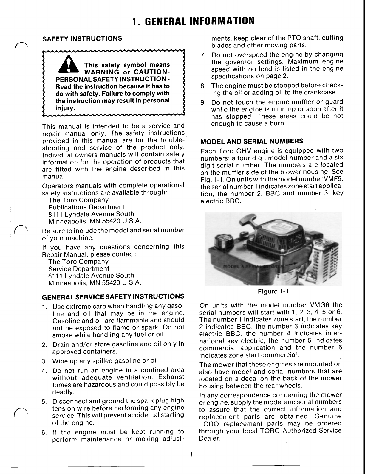
Each Toro OHV engine is equipped with two
numbers: a four digit model number and a six
digit serial number. The numbers are located
on the muffler side of the blower housing. See
Fig. 1-1. On units with the model number VMF5,
the serial number 1 indicates zone start application, the number
electric BBC.
On units with the model number VMG6 the
serial numbers will start with 1,
The number.1 indicates zone start, the number
2 indicates BBC, the number
electric BBC, the number 4 indicates international key electric, the number
commercial application and the number
indicates zone start commercial.
The mower that these engines are mounted on
also have model and serial numbers that are
located on a decal on the back of the mower
housing between the rear wheels.
In any correspondence concerning the mower
or engine, supply the model and serial numbers
to assure that the correct information and
replacement parts are obtained. Genuine
TORO replacement parts may be ordered
through your local TORO Authorized Service
Dealer.
2,
Figure 1-1
2.
BBC and number
2,
3,
3
indicates key
5
3,
key
4, 5 or 6.
indicates
6
1
Page 9
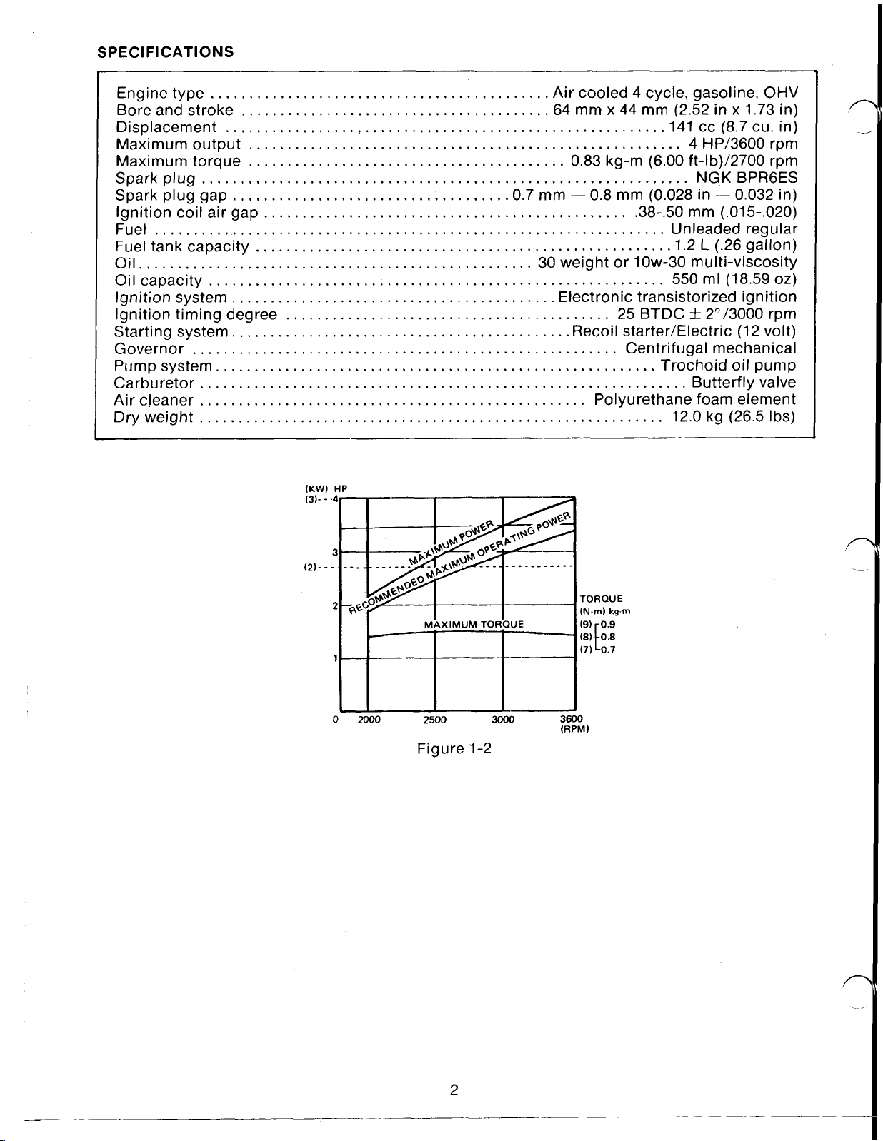
SPECIFICATIONS
Engine type Air cooled 4 cycle, gasoline,
Bore and stroke .64 mm
x
44 mm (2.52 in x 1.73 in)
OHV
Displacement 141 cc (8.7 cu. in)
Maximum output 4 HP/3600 rpm
Maximum torque 0.83 kg-m (6.00 ft-lb)/2700 rpm
Spark plug NGK BPR6ES
Spark plug gap .0.7 mm 0.8 mm (0.028 in 0.032 in)
Ignition coil air gap.. .38-50 mm (.015-,020)
Fuel Unleaded regular
Fuel tank capacity .1.2
Oil..
Oil capacity
30
weight or low-30 multi-viscosity
L
550
ml (18.59
(.26 gallon)
0Z)
Ignition system Electronic transistorized ignition
Ignition timing degree 25 BTDC rpm
Starting system. .Recoil starter/Electric (12 volt)
Governor Centrifugal mechanical
Pump system.. Trochoid oil pump
Carburetor Butterfly valve
Air cleaner Polyurethane foam element
Dry weight 12.0 kg (26.5 Ibs)
(KW)
HP
3
2
0
2000
2500
Figure 1-2
3000
3600
RPM)
TORQUE
(Nm)
kgrn
2
Page 10
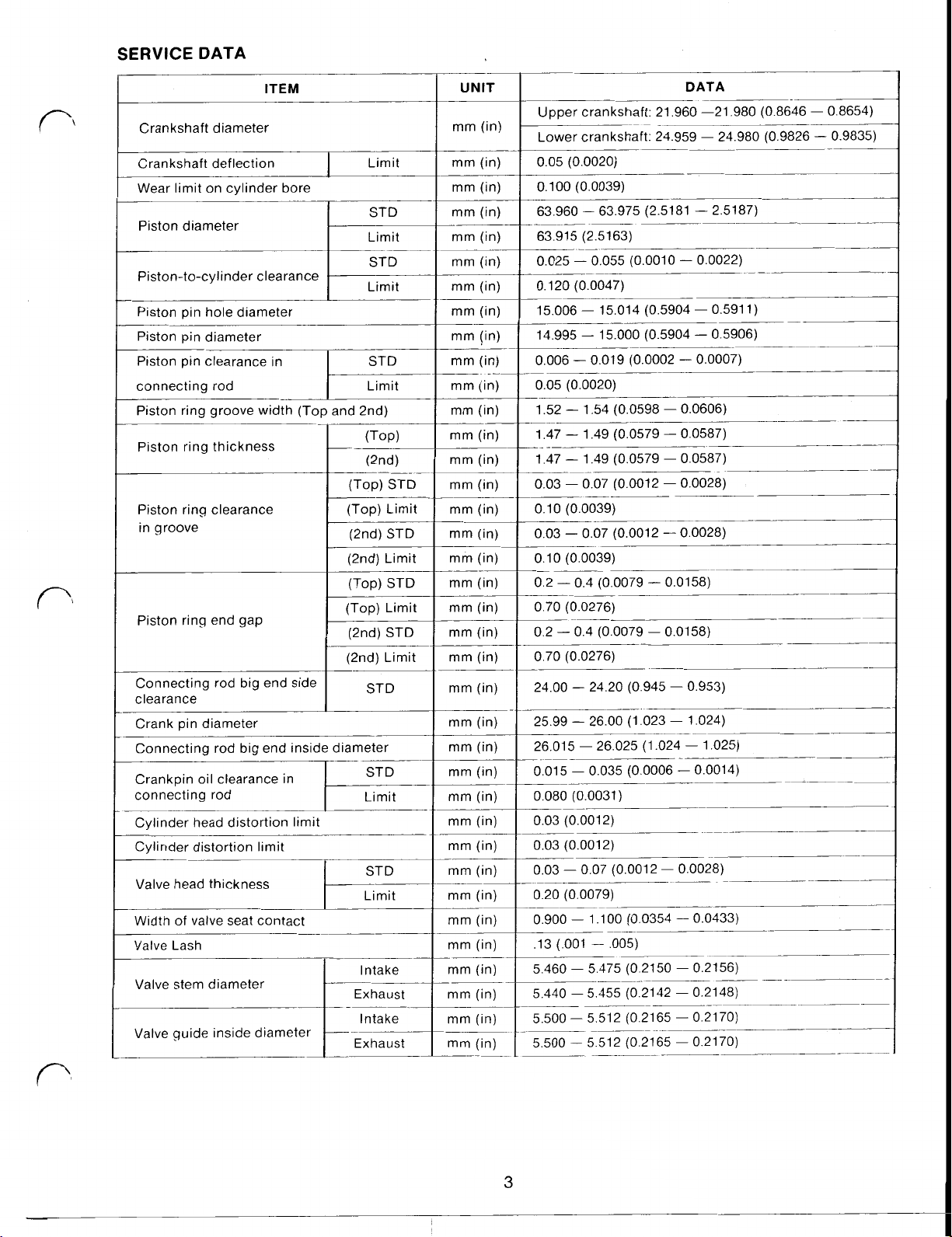
SERVICE
DATA
ITEM
Crankshaft diameter
Crankshaft deflection Limit
Wear limit on cylinder bore
Piston diameter
Piston-to-cylinder clearance
Piston pin hole diameter
Piston pin diameter
Piston pin clearance in
connecting rod Limit
Piston ring groove width (Top and 2nd)
Piston ring thickness
(Top) STD
_____-
Piston ring clearance
in groove
Piston ring end gap
Connecting rod big end side
clearance
Crank pin diameter
Connecting rod big end inside diameter
Crankpin oil clearance in
connecting rod Limit
__-
Cylinder head distortion limit
Cylinder distortion limit
Valve head thickness
Width of valve seat contact
Valve Lash
Valve stem diameter
Valve guide inside diameter
(Top) Limit
(2nd) STD
(2nd) Limit
(Top) STD
(Top) Limit
(2nd) STD
(2nd) Limit
I
Intake
_-
Exhaust
Intake
Exhaust-
STD
Limit
STD
Limit
(TOP)
(2nd)
ST D
STD
___-
STD
UNIT
mm (in!
____-
mm (in)
mm (in)
mm (in)
____-
mm (in)
mm (in)
mm (in)
mm (in)
mm (in)
mm (in)
mm (in)
mm (in)
mm (in)
mm (in)
mm (in)
mm (in)
mm (in)
mm (in)
mm (in)
mm (in)
mm (in)
~-
mm (in)
mm (in)
mm (in)
mm (in)
mm (in)
mm (in)
~-
mm (in)
mm (in)
mm (in)
mm (in)
mm (in)
mm (in)
____-
mm (in)
mm (in)
mm (in)
mm
(in)
DATA
Upper crankshaft: 21.960 -21.980 (0.8646 0.8654)
Lower crankshaft: 24.959 24.980 (0.9826 0.9835)
0.05
(0.0020)
0.100 (0.0039)
63.960 63.975 (2.5181 2.5187)
63.915 (2.5163)
0.055
0.025
0.120 (0.0047)
15.006 15.014 (0.5904 0.591 1)
14.995 15.000 (0.5904 0.5906)
0.006 0.019 (0.0002
0.05
(0.0020)
1.52 1.54 (0.0598 0.0606)
1.47 1.49 (0.0579 0.0587)
1.47 1.49 (0.0579 0.0587)
0.03 0.07 (0.0012 0.0028)
0.10 (0.0039)
0.03 0.07 (0.0012 0.0028)
0.10 (0.0039)
0.2 0.4 (0.0079 0.0158)
0.70 (0.0276)
0.2 0.4 (0.0079
0.70 (0.0276)
24.00 24.20 (0.945 0.953)
25.99 26.00 (1.023 1.024)
26.015 26.025 (1.024 1.025)
0.01
5
0.080 (0.0031)
0.03 (0.0012)
0.03 (0.0012)
0.03
0.07
0.20 (0.0079)
0.900 1.1
.13 (.001
5.460 5.475 (0.2150 0.2156)
5.440 5.455 (0.2142 0.2148)
5.500
5.500
(0.0010 0.0022)
0.0007)
0.0158)
0.035 (0.0006 0.0014)
(0.001 2 0.0028)
00
(0.0354 0.0433)
,005)
5.512 (0.2165 0.2170)
5.51 2 (0.21 65 0.21 70)
3
Page 11
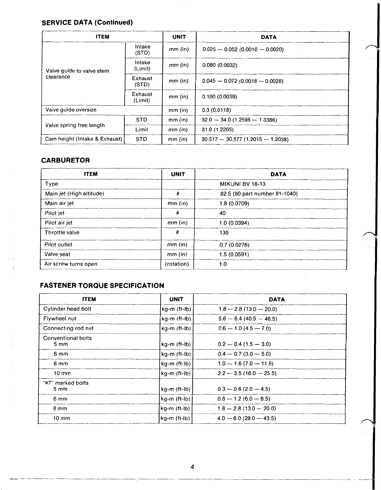
SERVICE DATA (Continued)
ITEM
Intake
(STD)
Intake
Valve guide
clearance Exhaust
Valve guide oversize
Valve spring free length
to
valve stem
(Limit)
(STD)
Exhaust
(Limit)
Limit
CARBURETOR
ITEM
TYPE
Main jet (High altitude)
Main air jet
Pilot jet
Throttle valve
UNIT
mm(in)
mm (in)
mm (in)
mm (in)
mm (in)
mm (in)
mm (in)
mm (in)
0.025 0.052 (0.0010 0.0020)
0.080 (0.0032)
0.045 0.072 (0.0018 0.0028)
0.100 (0.0039)
0.3
(0.01 18)
32.0 34.0 (1.2598 1.3386)
.O
(1.2205)
31
30.51 7 30.577 (1.201
UNIT
#
mm (in)
#
mm (in) Pilot air jet
#
MlKUNl BV
82.5 (80
part number
1.8 (0.0709)
40
1
.O
(0.0394)
130
DATA
5
18-13
1.2038)
DATA
81-1040)
Pilot outlet
Valve seat
Air screw turns open
FASTENER TORQUE SPECIFICATION
ITEM
Cylinder head bolt
Flywheel nut
Connecting
Conventional bolts
5
6
8
10
"#7"
marked bolts
5
6
8
10
mm
mm
mm
mm
mm
mm
mm
mm
rod
nut
kg-m (ft-lb:
kg-m (ft-lb:
kg-m (ft-lb:
kg-m (ft-lb)
kg-m (ft-lb)
kg-m (ft-lb)
kg-m (ft-lb)
kg-m (ft-lb)
kg-m (ft-lb)
kg-m (ft-lb)
kg-m (ft-lb)
mm (in)
mm (in)
(rotation)
UNIT
0.7
(0.0276)l
1.5 (0.0591)
1
.o
DATA
1.8 2.8 (13.0 20.0)
5.6 6.4
0.6 1
0.2 0.4 (1.5
0.4 0.7 (3.0
1
.O
2.2
(40.5
.O
(4.5
1.6
(7.0
3.5
(16.0 25.5)
46.5)
7.0)
3.0)
5.0)
11.5)
0.3 0.6 (2.0 4.5)
0.8 1.2 (6.0
8.5)
1.8 2.8 (13.0 20.0)
4.0 6.0 (29.0 43.5)
I
I
4
Page 12
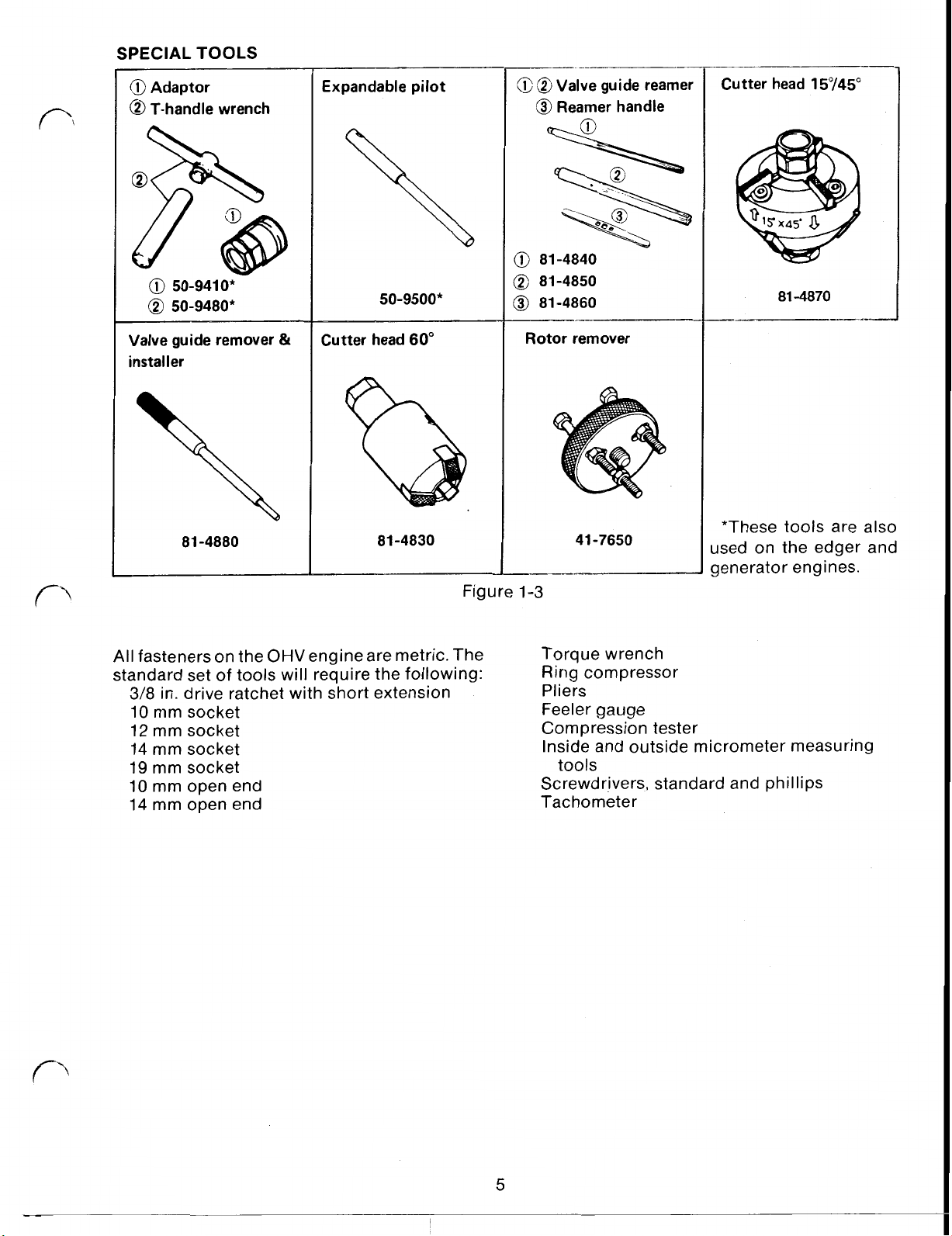
SPECIAL TOOLS
@
Adaptor
T-handle wrench
50-9410*
50-9480*
Valve guide remover
installer
81 -4880
Expandable pilot
Cutter
&
50-9500*
head
60"
81 -4830
Figure
Valve guide reamer
Reamer handle
A
81-4840
81-4850
81-4860
Rotor remover
41 -7650
1-3
Cutter
head
81
-4870
*These tools are also
used on the edger and
generator engines.
I
All
fasteners on the
standard set
3/8
in. drive ratchet with short extension
10
mm socket
12
mm socket
14
mm socket
19
mm socket
10
mm open end
14
mm open end
OHV
engine are metric. The
of
tools will require the following:
Torque wrench
Ring compressor
Pliers
Feeler gauge
Compression tester
Inside and outside micrometer measuring
tools
Screwdrivers, standard and phillips
Tachometer
5
Page 13
2.
MAINTENANCE
AIR CLEANER
The consumer air cleaner should be serviced
every
air cleaner is of a two part design: the foam
pre-cleaner should be serviced every 25 hours
and the paper element every
frequent service for both air cleaners may be
required in dusty or dirty conditions.
Consumer Air Cleaner Maintenance
1.
2. Clean loose debris from the air cleaner
3.
25
hours of engine use. The commercial
50
hours. More
Stop the engine and pull the high tension
wire off the spark plug.
body.
Push
in
the locking tabs and lift off the air
2-1.
cleaner cover. See Fig.
Clean the cover.
Figure 2-2
PAPER ELEMENT
Figure 2-1
4.
Remove the foam element. See Fig.
5.
Wash the element in soap and water.
Squeeze
element may tear.
6.
Dry the element and saturate it with
teaspoons of SAE
the element
7. Reinstall the air cleaner element and cover.
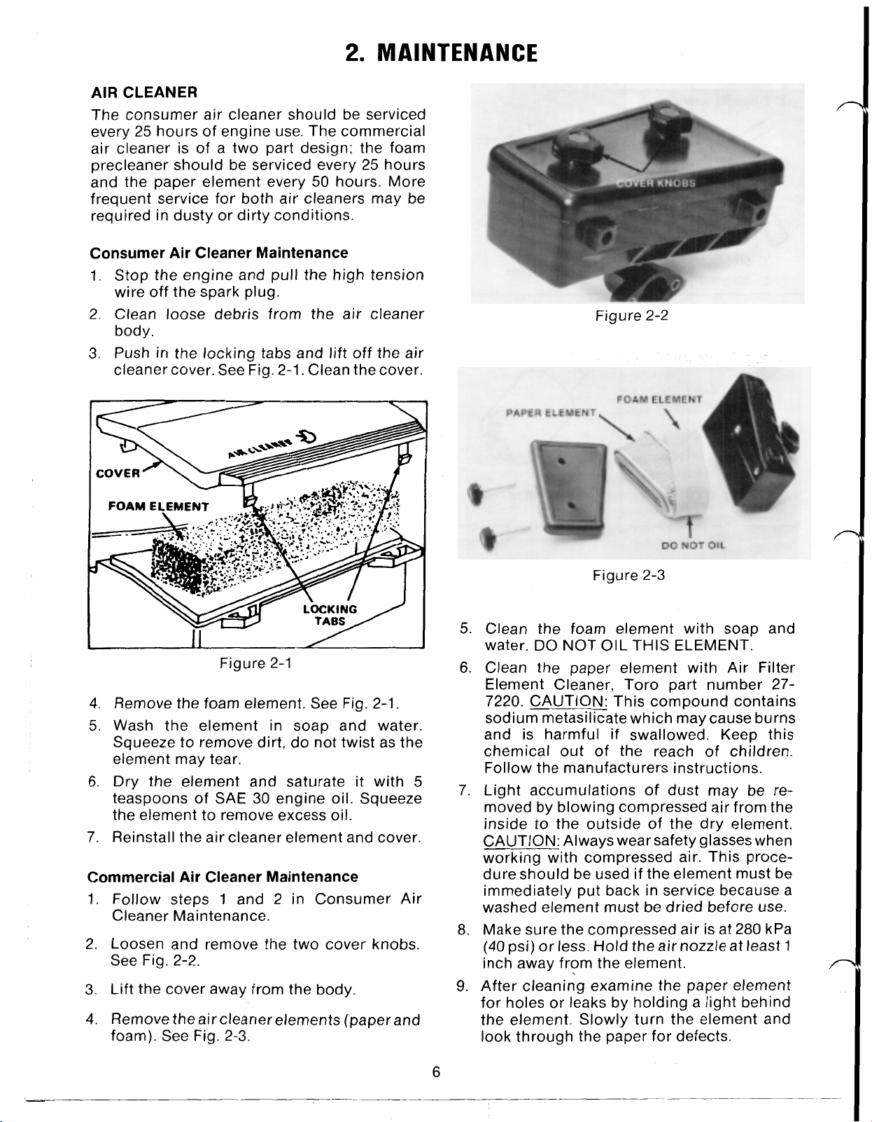
Commercial Air Cleaner Maintenance
1.
Follow steps
Cleaner Maintenance.
2. Loosen and remove the two cover knobs.
See Fig. 2-2.
3.
Lift the cover away from the body.
4.
Remove the air cleaner elements (paper and
foam). See Fig. 2-3.
to
remove dirt, do not twist as the
30
engine oil. Squeeze
to
remove excess oil.
1
and 2
in
Consumer Air
2-1.
5
Figure
5.
Clean the foam element with soap and
DO
water.
6.
Clean the paper element with Air Filter
Element Cleaner, Toro part number 27-
7220. CAUTION: This compound contains
sodium metasilicate which may cause burns
and is harmful
chemical
Follow the manufacturers instructions.
7.
Light accumulations
moved by blowing compressed air from the
inside
CAUTION: Always wear safety glasses when
working with compressed air. This procedure should be used if the element must be
immediately put back in service because a
washed element must be dried before use.
Make sure the compressed air is at 280 kPa
8.
(40 psi) or less. Hold the air nozzle at least
inch away from the element.
After cleaning examine the paper element
9.
for holes or leaks by holding a light behind
the element. Slowly turn the element and
look through the paper for defects.
NOT
out
of the reach
to
the outside of the dry element.
2-3
OIL
THIS
if
swallowed. Keep this
ELEMENT.
of
dust may be re-
of
children.
1
6
Page 14
CHANGING OIL
2
Change oil after the first
hours of use and
every 25 hours thereafter. Run the engine to
warm the oil before draining.
1. Stop the engine and pull the high tension
wire off the spark plug.
2. Drain gasoline from the fuel tank. Refer
Fuel System on page
8.
to
3. Raise the left side of the mower at least 12
inches and remove the drain plug. Use a 12
mm socket or wrench.
4. Insert an oil drain tube, part number 56-
6680, over the drain opening and lower the
mower. Raise the right side of the mower
until all the oil has flowed into a drain pan.
See Fig. 2-4.
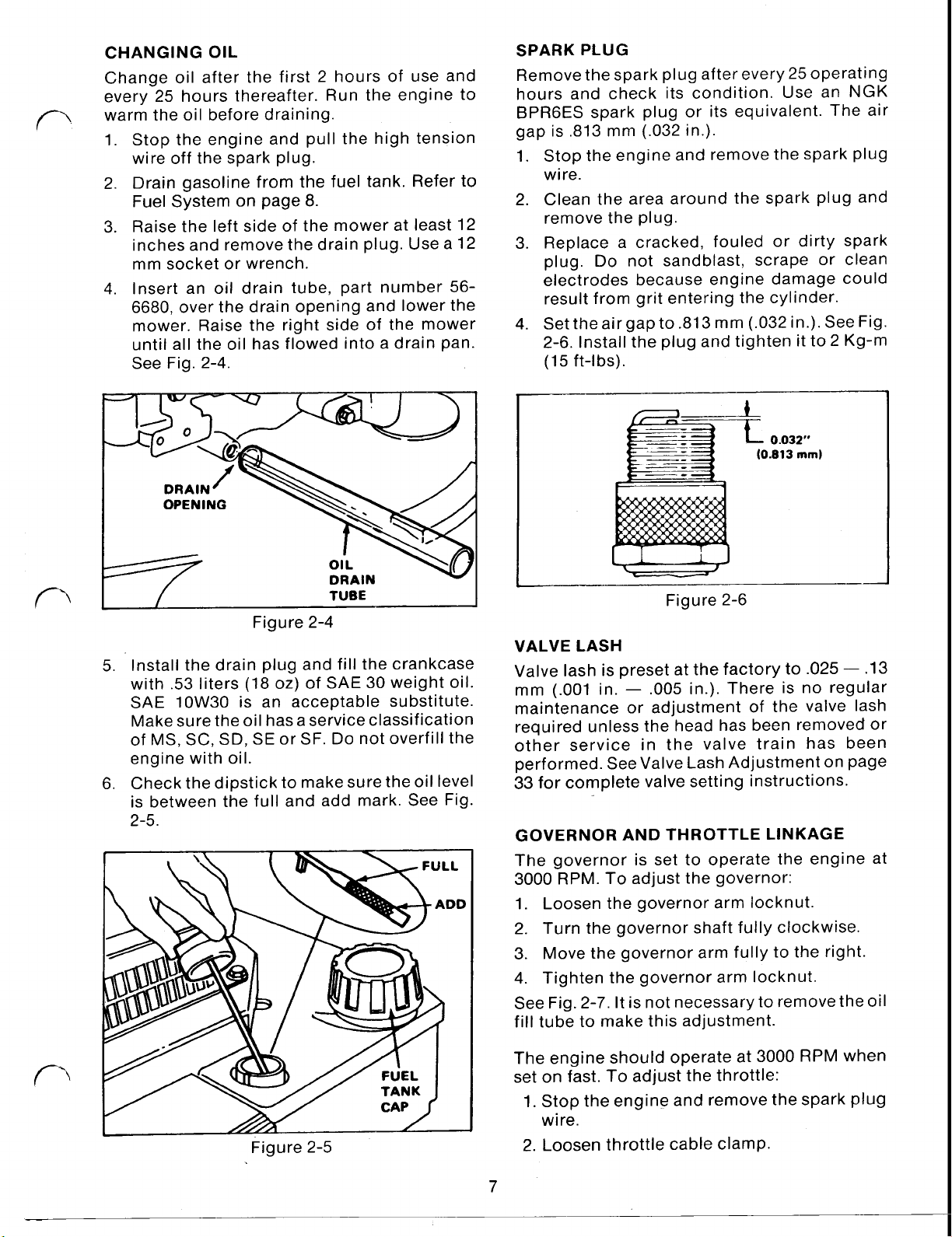
SPARK PLUG
Remove the spark plug after every
25
operating
hours and check its condition. Use an NGK
BPR6ES spark plug or its equivalent. The air
gap is ,813 mm (.032 in.).
1. Stop the engine and remove the spark plug
wire.
2. Clean the area around the spark plug and
remove the plug.
3.
Replace a cracked, fouled or dirty spark
Do
plug.
not sandblast, scrape or clean
electrodes because engine damage could
result from grit entering the cylinder.
4.
Set the air gap to .813 mm (.032 in.). See Fig.
2-6. Install the plug and tighten it to
(1
5
ft-l bs).
0.032"
(0.813
mm)
2
Kg-m
I
01
L
DRAIN
I
TUBE
Figure 2-4
5.
Install the drain plug and fill the crankcase
with .53 liters (18 oz) of SAE
30
weight oil.
SAE 10W30 is an acceptable substitute.
Make sure the oil has a service classification
of
MS,
SC,
SD,
SE or SF.
Do
not overfill the
engine with oil.
6. Check the dipstick to make sure the oil level
is between the full and add mark. See Fig.
2-5.
I
Figure 2-6
VALVE LASH
Valve lash is preset at the factory to
mm (.001 in.
.005
in.). There is no regular
.025
maintenance or adjustment of the valve lash
required unless the head has been removed or
other service in the valve train has been
performed. See Valve Lash Adjustment on page
33
for complete valve setting instructions.
GOVERNOR AND THROTTLE LINKAGE
The governor is set to operate the engine at
3000
RPM. To adjust the governor:
1. Loosen the governor arm locknut.
2. Turn the governor shaft fully clockwise.
3.
Move the governor arm fully to the right.
4. Tighten the governor arm locknut.
See Fig. 2-7. It is not necessary to remove the
fill tube to make this adjustment.
.13
oil
Figure 2-5
The engine should operate at 3000 RPM when
set on fast. To adjust the throttle:
1.
Stop the engine and remove the spark plug
wire.
2. Loosen throttle cable clamp.
7
Page 15

Figure 2-7
3.
Align the holes
throttle lever.
4.
Insert a tight fitting pin; e.g. 1/8 in. drill bit.
5.
Move the throttle control on the handle
“fast” and tighten the cable clamp screw.
6.
Back out the upper screw until only a few
threads remain in the throttle lever.
7.
Install the plug wire and start the engine.
8. Using
engine speed
9.
Now turn the upper screw until it
contacts the throttle lever tang (a maximum
gap of ,020 in. is acceptable).
10.
Remove the alignment pin.
11.
On BBC engines, set the throttle control on
the handle in the “stop” position. Bend the
grounding tang until
throttle lever. See Fig. 2-8.
only
in
the throttle bracket and
the lower screw, adjust the
to
3000 RPM.
just
barely
it
just contacts the
to
IGNITION
The
OHV
engine uses a solid state ignition
system with timing fixed at
2
degrees at 3000 RPM. Ignition timing is not
adjustable. However, ignition timing may
change
flywheel key has sheared. The engine may
continue
formance. Under these conditions the timing
will advance, making starting and running
difficult. The coil
mm (.015 in.).
FUEL SYSTEM
The fuel tank has a capacity of 1.21
should be drained of fuel before changing oil
and at the end of each season. To drain the fuel:
1.
2. Use a pump or syphon to transfer the
!
CAUTION: Gasoline is highly flammable, handle
flame or spark while handling gasoline.
The fuel system is equipped with an 84 micron
in-line fuel filter. See Fig. 2-9.
occurs, this filter should be examined for
contamination. There is no “in tank” filter on
this engine.
if
a blade impact has occurred and the
to
run with a degradation
to
flywheel air gap is set at .38
Pull off the spark plug wire
gasoline into a clean gasoline container.
CAUTION: Gasoline
flammable, handle
Do
not smoke
spark while handling gasoline.
it
carefully.
or
allow any open flame or
Do
not smoke or allow any open
25
degrees BTDC
L
(44
is
highly
it
carefully.
If
poor running
in
oz)
per-
and
Governor and throttle adjustments should be
made on an as needed basis only.
Throttle
Control
Figure 2-8
Assembly
Figure
The fuel tank cap should be periodically
examined for proper venting. The cap is fitted
with a sealing disc but cannot be disassembled.
See Fig
2-10.
2-9
Page 16

CARBURETOR
The
OHV
engine is equipped with a Mikuni
BV
18-1 3 float bowl type Carburetor. The standard
main jet is a number 82.5. This number is
stamped in the base of the jet. The only
adjustment on the carburetor is the pilot system
pilot screw. The pilot screw should be set one
turn open. See. Fig. 2-1
1.
This will have the
most effect at idle or low speed with no load on
the engine.
PILOT
ONE
SCREW
TURN
OPEN
inlet needle with a
stainless
steel tip. The needle
is replaceable.
The carburetor is also fitted with a bowl drain
screw that can be used to drain fuel out of the
bowl after the tank is drained. See Fig. 2-12.
Open the screw and drain the fuel into a
suitable container.
Figure 2-12
STORAGE
To insure long engine life and easy engine
starting, it is important to follow these storage
procedures at the end
1.
Drain gasoline from the tank. Refer to Fuel
System
2.
Drain gasoline from the carburetor bowl.
Refer
3.
Drain the engine oil; refer
on
on
page
to
Carburetor Maintenance above.
page
7.
of
each season:
8.
to
Changing Oil
PlLO
Figure 2-1 1
The carburetor on theVMF5 model uses a brass
fuel inlet seat (not replaceable) and an inlet
needle with a Viton tip. The needle is replace-
able. The carburetor on the
VMG6
model uses a
Viton fuel inlet seat (not replaceable) and an
9
4.
Remove the spark plug and pour
spoons of
SAE 30
or 1OW-30 oil into the
cylinder. Pull the starter rope slowly to coat
the inside
of
the cylinder. Install the spark
plug and tighten it to 2.0 kg-m (15 ft-lbs).
5.
Service the air cleaner; refer to Air Cleaner
Maintenance on page
6.
Clean dirt from all areas of the engine.
7.
Tighten all nuts, bolts and screws.
8.
Refill the crankcase with oil; refer to
Changing Oil on page
6.
7.
2
table-
Page 17

3.
TROUBLESHOOTING AND TEST PROCEDURES
This section has been divided into the troubleshooting and service of individual systems.
To
determine what system needs to be evaluated, some preliminary troubleshooting is necessary.
These are checks that can be made with little or no disassembly and would normally be made with
the customer or owner present.
The following form is useful in documenting engine conditions during preliminary troubleshooting:
PRELIMINARY TROUBLESHOOTING
PRODUCT
MODEL/SERIAL
ENGINE MODEL
ENGINE SERIAL
DISTRIBUTORp- DEALER NAME
EVALUATOR DEALER CONTACT/PHONE
PRE-EVALUATION INFORMATION
Purchase Date Date Failed How Used? Residential Commercial
Fuel Mix: Ratio OiVBrand Gasoline/Brand
to
Symptoms Prior
Failure?
~___.-
CUSTOMER NAME
ADDRESS
PHONE
Engine Compressions? N/A---. PSI ___Compression Specification
VISUAL ANALYSIS
COOLING FINS: CARBURETOR: FUEL CAP: MUFFLER/EXHAUST PORTS:
Clean Clean- Vented Clean-- CarbonedObstructed Contaminated Clogged CRANKCASE: Clean
AIR CLEANER ASM: Comments Distorted Contaminated Burned-
Clean FUEL FILTER: SPARK PLUG: Clean- METAL DISCOLORATION?
Dirty Clean Carboned Fouled- NO---.-Damaged Clogged Type Yes
PSI
10
Page 18

TROUBLESHOOTING
CHART
The information gathered in preliminary troubleshooting can now be used with the following
troubleshooting chart to determine individual systems
PROBLEM
Engine does not St;
Engine starts hard
or loses power.
Engine operates
eratically.
Engine idles poorly.
Engine skips at
high speed.
Engine overheats.
1.
2.
3.
4.
5.
6.
7.
8.
9. Valves not closing.
1.
2.
3.
1.
2.
3.
1.
2.
3.
4.
~ ~~
1.
1.
2.
3.
4.
POSSIBLE CAUSES
~____________.
Throttle not in CHOKE position.
Gas tank is empty.
Air cleaner element is
dirty.
Spark plug is loose.
Spark plug wire is loose or
disconnected from spark plug.
Spark plug gap is incorrect.
Spark plug is defective
Carburetor is flooded with gasoline.
Dirt, water or stale gas in fuel tank
Vent hole in fuel tank cap is plugged.
Air cleaner is dirty.
Spark plug is defective.
Spark plug gapped incorrectly.
Air cleaner is dirty.
~
Air cleaner is dirty.
Oil level in crankcase is low.
Air slots in engine shroud are plugged.
Cooling fins and air passages under
engine blower housing are plugged.
Air gap between electrodes of spark
plug
is too close.
Cooling air flow is restricted
Oil
level in crankcase is low.
Incorrect spark plug.
Low oil level.
to
be serviced.
_.___~~___~___
~____
~-
1.
2.
3.
4.
5.
6.
7.
8. Remove air cleaner element and pull
9. Check valve lash. See page
1.
2.
3.
_____~____--~-___
1.
2.
3.
____
1.
2.
3.
4.
and air passages.
1.
Set air gap
See page
_~___
1.
Remove any obstruction from
shroud, blower housing, air passages,
and cooling fins on engine.
2.
Add
3.
Install new, correctly gapped plug.
See page
1.
Change or add oil. Inspect for engine
damage. See page
CORRECTIVE ACTION
Move throttle to CHOKE.
Fill fuel tank with gasoline.
Clean air cleaner element.
See page
Tighten spark plug to proper
specification. See page
Install spark plug wire on spark plug.
Set air gap to proper specification.
See page
Install new, correctly gapped plug.
See page
starter rope continuously until
carburetor clears itself and engine
starts. When engine starts, stop it and
install air cleaner element. See
page
Drain gas and clean fuel tank. Fill
tank with clean, fresh gasoline. See
page
Clean or replace fuel tank cap. See
page 8-9.
Clean the air cleaner element. See
page
Install new, correctly gapped plug.
See page
Set air gap to proper specification.
See page
Clean the air cleaner element. See
page
Clean the air cleaner element. See
page
Add
Remove obstruction from slots.
Remove obstruction from cooling fins
6.
7.
7.
6.
8.
6.
7.
7.
6.
6.
oil
to crankcase. See page
to
proper specification.
7.
_~
oil
to crankcase. See page
7.
__
7.
7.
____~___
______
33.
7.
slots
7.
in
11
Page 19

CARBURETOR
Removal
1.
System page 8. The fuel tank is held in place
with two screws and is removed by pulling it
straight up. Drain the carburetor fuel bowl
and disconnect the fuel hose from the
carburetor. See Fig.
-
Carburetor
Drain and remove the fuel tank; refer to Fuel
3-1.
Figure 3-1
rod
to
allow it to be unhooked after the
carburetor has been removed.
Figure 3-3
5.
The bowl of the carburetor may be removed
by unscrewing the retaining nut on the
bottom of the bowl. See Fig. 3-4. The float
and spacer (that limits float drop) are visible
in this photograph.
2. Remove the single screw retaining the air
cleaner and dipstick tube and the two nuts
retaining the air cleaner to the carburetor.
See Fig.
the carburetor. Remove the breather hose
from the fitting on the air cleaner.
3. Lift the choke rod off the Carburetor. The
rod has a
the body of the air cleaner. See Fig. 3-3.
Please note the position of the gasket
between the air cleaner and carburetor. The
raised rib on the metal gasket should face
the air cleaner.
4.
The carburetor may be pulled off the studs.
There is enough travel in the throttle control
3-2.
Pull the air cleaner away from
Figure 3-2
90"
bend as it is held
in
place by
Figure 3-4
6.
The standard main jet is a #82.5 and is
equipped with a spacer/washer. The float
and inlet needle may be removed by pulling
out the float hinge pin. See Fig. 3-5. Please
of
note: one end
slightly. The pin must be removed from this
end.
INLET NEEDLE
the hinge pin is flattened
Figure 3-5
Page 20

7. The pilot jet may be removed next. The pilot
jet is a
#40
and can be cleaned or replaced.
Fuel flows through the small opening in the
end of the jet and air enters through the
holes in the side. The opening on the top
has no function as it is plugged.
The pilot screw controls air in the pilot
circuit. It should be open one full turn. See
Fig. 3-6.
Figure 3-6
8.
Carburetor disassembly is completed by
removing the choke and throttle shafts and
is
the main nozzle. The bowl gasket
also
replaceable and should be removed prior to
service or cleaning of the carburetor. See
Fig. 3-7. To withdraw the choke and throttle
shaft, the choke and throttle plates must be
removed. Each plate is retained with two
screws.
Service Carburetor
The metallic body of the carburetor may be
cleaned in carburetor cleaner. Plastic parts may
be damaged by some carburetor cleaners.
Carburetor passages may be cleaned out with
compressed air.
CAUTION!
safety glasses when
compressed air.
Be sure
to
using
wear
Replace any components that show wear or
damage. The inlet needle is replaceable but the
seat is not.
If
it is suspected that the seat is leaking, the
carburetor can be pressure tested after it has
been cleaned. Use Toro pressure tester, number 41-7910. If the seat is good, it will hold
kg/cm2 (7 psi) for at least
10
seconds. This
.5
procedure should be completed with the car-
buretor turned upside down
the needle closed. See Fig. 3-8.
so
the float holds
If
the pressure
leaks down, replace the needle and try the test
again.
If
the carburetor fails again, the seat is
bad and the carburetor must be replaced.
Figure 3-7
Throttle Shaft
Gasket
Nozzle
Figure 3-8
Reassembly Carburetor
1. Install the choke and throttle shafts. Check
Fig. 3-3 and 3-7 for proper orientation of the
shafts.
2. Install the choke and throttle plates. Use a
thread locking compound such as Loctite
271 on the screws.
3. Replace the main nozzle and bowl gasket.
4. Install the pilot jet and pilot screw. See Fig.
3-6. The pilot screw should be one turn open.
5.
Hook
the inlet needle into the float and
secure the float and needle in place with the
hinge pin. See Fig. 3-9.
13
Page 21

Figure 3-9
Figure
3-11
6. Remount the bowl and gasket.
7.
Mount the gaskets and spacer on the studs.
The correct sequence is described in Fig.
3-10.
Figure 3-10
8.
Hook the throttle control rod and spring into
the governor arm and throttle, then mount
the carburetor on the studs.
9.
Remount the air cleaner. Make sure to
install the spacer washer on the screw that
retains the air cleaner and oil fill tube. Refer
to Fig. 3-2.
10. Install the fuel tank and reconnect the fuel
hose. Be sure to route the fuel hose behind
the governor arm.
GAS CAP
Disassembly
1.
The gas cap used on the OHV engine is a
two piece design, however; no disassembly
is recommended. The inner sealing disc is
riveted into the plastic cap. See Fig. 3-1
1.
Service
1.
The tank should provide a free gravity flow
is
8.
84
higher
micron
of fuel to the carburetor (the tank
than the carburetor).
not evident (the engine is starving for fuel)
loosen the cap and see if fuel flow is
re-established.
If
2.
Reassembly
1.
2.
FUEL TANK AND FILTER
Disassembly
2. Disconnect the fuel hose at the carburetor.
3. Wipe up any fuel that may have drained out
Service
1.
2. This is the only fuel filter in the system and
3. If the fuel tank is dirty or contaminated,
the fuel flow improves, the cap is not
venting. Examine the vent hole in the
sealing disc and the cap to make sure they
are unobstructed.
Make sure the vent opening in the sealing
disc is turned 90 degrees from the vent
opening in the cap.
Remount the cap.
1.
Drain the fuel tank with a siphon pump.
Make sure you transfer the fuel to an
approved container.
Refer to Fig. 3-1.
of the hose when disconnected.
If
the fuel filter is plugged, clogged or dirty,
replace it. See Fig. 2-9 on page
must be replaced with the same
filter. Part number 56-6360.
wash the tank in parts cleaning solvent and
dry completely.
If
a free flow of fuel is
Page 22

Reassembly
1. Install a new filter, if necessary.
2. Mount the fuel tank using two spacers and
two screws.
3. Route the fuel hose behind the governor
arm.
4. Connect the hose to the carburetor.
IGNITION
Testing Spark Intensity
The ignition system can be checked for spark
intensity using a spark tester, part number
41
-7890.
1. Pull off the plug connector and remove the
spark plug.
2.
Inspect the plug for wear, carbon deposits
and damage. Replace the plug if damaged,
burnt or fouled.
3. Check for the correct plug gap and adjust, if
.7
necessary, to
in.).
4. Attach the spark tester and set the tester
gap to 4.2 mm (.166 in). (4 turns counterclockwise from the closed position.)
5.
Pull the starter and observe for spark.
6.
If
the spark is evident, the ignition system is
operating properly.
proceed to testing kill switch operation.
Testing Kill Switch Operation
There are two ignition kill systems, one for zone
start, and one for BBC and commercial applications. Both systems depend on a lever
contacting a grounding tang to ground the
ignition and stop the engine.
BBC
and Commercial
1. Make sure the kill wire is properly connected to the grounding tang on the throttle
control. See Fig. 3-12.
.8 mm (.028 in. .032
If
Kill
no spark
Systems
is
evident,
2.
3. In the “off” position, the throttle lever should
When the throttle control is in the “run”
position, the throttle lever should move
away from the ground tang. See Fig. 3-13.
In this position, the ground tang should not
have continuity to ground. This can be
tested by disconnecting the kill wire and
testing the tang with
the volt-ohmmeter on RX1 with one probe
on the tang and one probe on ground. There
should be a reading
continuity).
contact the ground tang. This will ground
the ignition and stop the engine. See Fig.
4.
3-1
a
volt-ohmmeter. Place
of
infinity (no-
Figure 3-1
2
Zone Start Applications
1.
Make sure the engine kill wire is connected
to the ground tang. See Fig. 3-15.
15
Figure 3-14
Page 23

Figure 3-15
2. With the control bail tensioned (run position), the brake pad is pulled away from the
flywheel and the brake lever is rotated away
from the ground tang. See Fig. 3-16. The
ground tang should not have continuity to
ground. This can be tested by disconnecting the kill wire and testing the tang to
ground continuity with a volt-ohmmeter.
Removal
1.
Drain the fuel tank. Refer
Ignition
to
Fuel System on
page 8.
2.
Remove the air cleaner assembly. Refer to
Air Cleaner Removal on page 12.
3. Remove the shrouding, including one screw
retaining the muffler guard. See Fig. 3-18.
Note: It is not necessary to remove the recoil
starter unless it is to be serviced.
Figure 3-18
Figure 3-16
3. With the control bail in the “off” or “stop”
position, the brake pad is against the fly-
wheel and the brake lever is contacting the
ground tang. This will ground the ignition
and stop the engine. See Fig.
3-17.
4.
The ignition coil may now be removed from
its mounting bosses. Be sure to unplug the
kill wire. See Fig. 3-19.
Figure 3-19
5.
If removal of the throttle bracket is
sary, remove the two fasteners shown
3-20.
I
neces-
in Fig.
Figure
3-17
Figure 3-20
Page 24

6.
If
removal of the brake assembly and switch
is necessary, remove the two retaining
screws. See Fig. 3-21.
Figure 3-21
Installation Ignition
1. Mount the brake assembly or throttle
assembly.
2.
Install the ignition coil. Mount a wire re-
tainer on either the right or left side of the
coil, depending on the brake system used.
Refer to Fig. 3-19.
3. Establish an air gap of .38
-.020) between the flywheel and ignition
coil. Use a feeler gauge or spacer of appro-
priate thickness. Tighten the ignition coil
fasteners.
4.
Reinstall all shrouding. Note:
the screw for the oil
5.
Mount the air cleaner assembly. Install the
long screw and spacer washers through the
air cleaner and dip-stick tube at this time.
Refer to Fig. 3-2.
6.
Mount the fuel tank. Route the fuel hose
behind the governor arm.
ELECTRIC STARTER AND ALTERNATOR
The electric starter used on the OHV engine
operates on 12 volts DC and is controlled by a
start switch and ignition kill switch. The battery
is under continuous charge with a 300 ma
alternator. See Fig. 3-22 for the OHV electric
start wiring schematic.
Testing Electric Starter
The starter motor fails to turn:
1. Check the battery, make sure it is connected
and fully charged. If the motor still does not
turn, go to step two.
fill
tube at this time.
.50
mm (.015
Do
not install
3. Apply 12 volts direct to the starter motor
If
1. Check the starter switch. Use a volt ohm-
2. Check the battery ground to the engine.
3. Check the wire connectors at the battery
If
1. Verify that the engine
2. Replace the motor as the internal com-
Figure 3-22
2. Remove the spark plug wire and disconnect
the starter motor plug.
terminals. See Fig. 3-23.
Figure 3-23
the motor turns:
meter. There should be continuity through
the switch in the “start” mode.
There should be continuity between the
negative battery terminal and the body
the engine.
and starter motor.
the motor does not turn:
is
not seized.
engine
ponents are not replaceable.
is
free go to step “2”.
If
of
the
17
Page 25

Testing Alternator
Battery does not charge during mower
operation:
1.
Check battery connections and alternator
connections to make sure they are complete
and secure. Check the connection points at
the battery, alternator wire, key switch and
all ground connections.
2. Measure the alternator output with the
engine at 3000 RPM. With the battery
connected, alternator output should be 13.2
volts DC. The voltage can be measured
between the red wire on the key switch and
the black ground wire.
3.
If
the measured voltage is 12 volts or less, it
indicates the alternator may not be charging.
Go
to step four.
4.
Complete a resistance test on the alternator
coil. This test may be completed without
removing the coil from the engine.
measurements are taken between the output wire and ground. Disconnect the wire
for these tests. For clarity, the coil has been
removed in the following figures.
5.
The alternator coil is equipped with a diode
assembly that will rectify the alternator
output. See Fig. 3-24.
All
Figure 3-25
7.
Reverse the leads and complete the test.
The measurement is 707 ohms. The meter
was on the 2000 ohm scale and the reading
is .707 or 707 ohms. See Fig. 3-26.
n
Figure 3-24
6. Check the diode and coil assembly with a
volt-ohmmeter. The meter in Fig. 3-25
indicates a resistance of infinity when a
numeral one appears to the left of the
decimal point. The measurement should be
infinity when the positive probe of the meter
is placed on the output wire. See Fig. 3-25.
The negative probe
ground terminal of the alternator coil.
is
connected to the
Figure 3-26
Removal Electric Starter
1.
Pull the spark plug wire off the spark plug.
2. Unplug the starter connector.
3.
Unscrew the two mounting screws as shown
in
Fig. 3-32.
4.
It
is not necessary to take shrouding off the
engine to remove the starter.
5.
The serviceable components on the starter
are shown in Fig. 3-27.
6.
The pinion is serviceable by removing the
retainer clip and then lifting the components
off the starter motor shaft.
Installation Electric Starter
1. Coat the starter motor worm shaft and pinion
teeth with a light coat of molybdenum di-
sulfide lubricant, Toro part number 505-37.
2. Assemble the starter motor components
shown
3. Install the starter motor and torque the
fasteners to 2.2 3.5 kg-m (16-25 ft-lb).
(Make sure you don’t pinch the alternator
wire under the starter motor.)
in
Fig. 3-27.
as
Page 26

Retainer
Pinion
Stop
Pinion
Figure 3-27
Removal Alternator
2,
1. Follow steps 1,
3 under Removal
Ignition on page 16.
2. Remove the two screws retaining the alternator to the engine block.
3. Pull the alternator wire and rubber grommet
out of the block.
Installation Alternator
1. Install the alternator and secure with two
fasteners. The screws should be tightened
to 1.0 1.6 kg-m (7-11 ft-lbs). Route the
wire and grommet through the opening in
the engine block. See Fig. 3-28.
RECOIL
All
STARTER
OHV
engines, including electric start, are
equipped with recoil starters. Recoil starter
service is performed as follows:
Removal and Disassembly
Recoil
Starter
1. Remove the four screws retaining the starter
to the blower housing. See Fig. 3-29. Note
the orientation
of
the recoil rope for proper
reassembly.
Figure 3-29
2. Turn the starter over and unwind the starter
rope to release spring tension on the starter
pulley. See step 1, 2, 3 on Rope Replacement, page
21.
Carefully remove the recoil
assembly retaining nut. The nut is under a
slight amount of spring pressure. Slowly
back off the nut until the spring pressure is
released. See Fig. 3-30.
Figure 3-30
3. Lift off the friction plate and expose the
starter pawl guide. See Fig. 3-31. Note how
the guide is installed and remove it.
Figure 3-28
2. Take care that the alternator wire does not
become pinched behind the starter motor.
3. Reinstall all shrouding, air cleaner and fuel
tank. Follow steps
Installation Ignition.
6 on page
17
on
Figure 3-31
4,
5,
19
I
Page 27

4. The friction spring is directly underneath
the starter pawl guide. The starter pawl is
also visible. See Fig. 3-32. Remove the
friction spring.
Figure 3-32
5.
Remove the shaft spacer. See. Fig. 3-33.
Figure 3-35
8.
The detensioned recoil spring will be captured in the bottom of the recoil pulley.
Carefully lift the pulley and recoil spring
free of the recoil housing. See Fig. 3-36.
Figure 3-33
6. Remove the nylon washer that is installed
under the spacer and spring. See Fig. 3-34.
Lift the starter pawl off at this time.
Figure 3-34
7.
The starter pawl pivots on the pin shown in
Fig. 3-35. Remove the pin.
Figure 3-36
9.
Turn the pulley over and examine the con-
dition of the recoil spring. It should be
as
retained in the pulley
On reassembly, the loop end of the spring
must be caught on the lip
recoil assembly.
Figure 3-37
seen in Fig.
of
the hub in the
3-37.
Page 28

Repair Recoil Starter
The most likely components on the recoil
starter to require repair are the coil spring and
starter rope.
‘A
when working with the recoil spring. If
the spring
could result.
Rope Replacement
1.
Rope replacement may be accomplished
without disassembly of the starter. First take
the starter off the engine.
2.
If
the pulley spring has not be detensioned,
withdraw about one foot of rope and while
holding the pulley in place, unwind the
remaining rope on the pulley.
3. Slowly release the rope until the pulley
spring fully relaxes. IMPORTANT.
turn the pulley any further in the clockwise
direction or the spring will unhook from the
center hub.
will turn freely in the counter-clockwise
direction without an increase in spring
tension. To correct, the pulley must be
removed and the spring re-hooked.
4. Untie the knot in the rope and replace with
new. The rope is 4mm (5/32 in.) in diameter
and 175cm (70 in.) long.
5.
Wrap the new rope around the pulley in a
counter-clockwise direction. See Fig.
6.
When the rope is fully wound on the pulley,
extend about two feet of rope, hold the
pulley in place and take two additional
wraps of rope around the pulley in a
counter-clockwise direction. This will preload the spring.
CAUTION:
glasses and use extreme care
is
suddenly released, injury
If
thespring un-hooks the pulley
Wear safety
Do
3-36.
not
7. Re-install the recoil starter.
Spring Replacement
1.
Follow steps one through nine under
“Recoil Starter Removal and Disassembly”
on page
2. Carefully remove the broken spring to
prevent rapid expansion of the spring.
CAUTION: Wear safety glasses and use
extreme care to prevent injury.
3. The replacement spring is provided with a
wire retainer to hold it together.
4. Place the spring in the pulley and release
from its retainer.
5.
The spring should be installed in the pulley
as shown in Fig. 3-37.
6.
If
the spring has expanded outside the
pulley, it can be reinstalled by first placing
the hook end into the pulley. See Fig. 3-37.
7. Wind the spring into the pulley in a counterclockwise direction from the outside until
the spring is fully retained.
8.
Place the pulley in the recoil housing and
turn it slowly in a counter-clockwise direction, with a slight down pressure, until the
pulley drops down indicating the spring is
hooked on the center hub.
Reassembly
1.
Install the pawl-pivot pin. See Fig. 3-35.
2. Install the nylon washer, starter pawl and
spacer. See Figs. 3-34, 3-33.
3. Install the friction spring and pawl guide.
See Figs. 3-32, 3-31.
4.
Install the friction disc and mounting nut.
Use a thread locker on the nut: e.g. Loctite
242. See Fig. 3-30.
5.
Install the recoil rope. Refer to steps
Rope Replacement on page 21.
19.
5
&
6
it
of
21
Page 29
4.
ENGINE DISASSEMBLY, INSPECTION AND REASSEMBLY
DISASSEMBLY
Recoil Starter
1.
Remove the four screws retaining the
starter.
If
the recoil starter must be disassembled,
2.
to
refer
on page 19-20.
Fuel Tank
1.
Drain the tank per instructions on page
2.
Drain the carburetor per instructions on
page 9.
3. Disconnect the fuel hose.
4. Remove the two screws retaining the fuel
tank.
5.
Lift the fuel tank off the engine.
Air
Cleaner
1.
Remove the air cleaner assembly. Refer to
steps one and two of Carburetor Service on
page 12.
Cooling Shrouds
1.
Remove the three screws retaining the
engine top cover.
2.
Remove the three screws retaining the
muffler shroud. See Fig. 4-1.
Recoil Starter Removal and Repair
8.
Figure 4-2
Alternator
1.
If
the engine is an electric start model,
remove the alternator coil.
2. Refer
Ignition Coil
1.
Remove the ignition coil.
2. Refer
Oil Fill Tube
1. Make sure the engine has been drained of
oil. Refer
12 mm wrench
2. Remove the two screws retaining the oil fill
tube. Use a
to
“Removal-Alternator” on page 19.
to
“Removal-Ignition” on page
to
Changing Oil on page
or
socket
10
mm socket. See Fig. 4-3.
on
the drain plug.
7.
16.
Use a
Figure 4-1
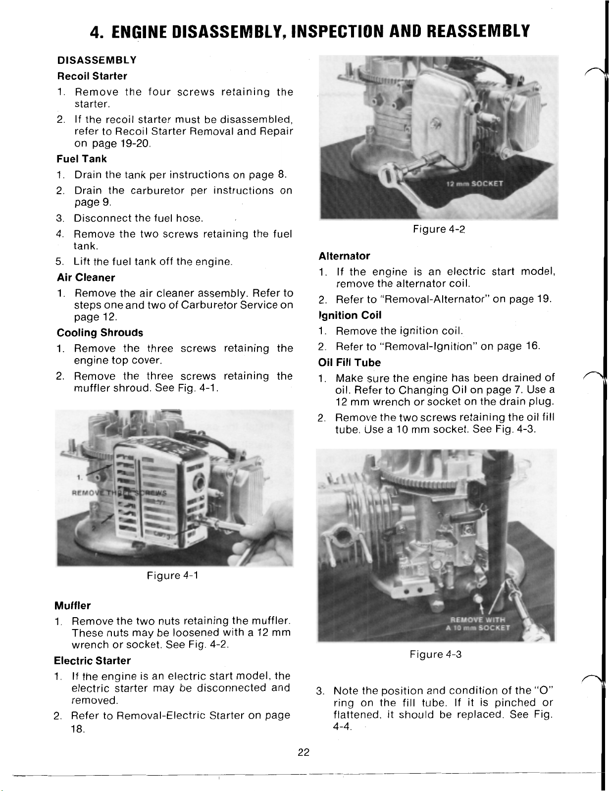
Muffler
1.
Remove the two nuts retaining the muffler.
These nuts may be loosened with a 12 mm
wrench or socket. See Fig. 4-2.
Electric Starter
1.
If
the engine is an electric start model, the
electric starter may be disconnected and
removed.
2. Refer to Removal-Electric Starter on page
18.
Figure 4-3
3. Note the position and condition of the
ring on the fill tube.
flattened, it should be replaced. See Fig.
4-4.
If
it is pinched or
“0”
Page 30

Figure 4-4
Throttle Control and Carburetor
1.
Refer to “Removal-Carburetor’’ on page
2.
Refer to disassembly steps
12-13
if further carburetor service is necessary.
5,6,7,8
on page
Flywheel
1.
Use a screwdriver through the starter cup to
hold the flywheel in place.
2.
Use a
19
mm socket to remove the flywheel
nut. See Fig. 4-5.
12.
5.
Examine the condition of the flywheel taper,
keyway and crankshaft key and taper. See
Fig. 4-7.
Figure 4-7
Breather
1. Remove the two screws retaining the breather assembly cover. Use a 10 mm socket or
wrench. See Fig. 4-8.
Figure 4-5
3.
After the flywheel nut is removed, unscrew
the three fasteners retaining the starter cup.
4.
Mount flywheel puller#41-7650 and remove
the flywheel. Insert the screws for the puller
into the same holes used by the starter cup
retaining screws. See Fig. 4-6.
Figure 4-6
Figure 4-8
2.
Under the cover will be a gasket, a reed plate
and another gasket.
Figure 4-9
23
Page 31

3. The reed retainer and reed must be mounted
“up” as seen in Fig. 4-9.
Cylinder Head Assembly
1. Remove the four screws retaining the valve
cover. See Fig. 4-10. Don’t lose the washers
under each screw.
Figure 4-10
2. If the head assembly is to be completely
torn down, remove each valve rocker arm.
This step is not essential to the removal of
the cylinder head. Hold the adjusting nut
with a 14 mm wrench and loosen the jam nut
with a 10 mm wrench. See Fig. 4-1 1. Remove
the nuts, rocker arms and push rods.
HEAD
Figure 4-12
GASKET
Figure
4-11
3. Remove the four head bolts. Use a 12 mm
socket with a short extension. Two of the
head bolts are under the valve cover. See
Fig. 4-12.
4. Pull the head away from the engine block.
Do
not lose the two aligning pins. The head
gasket will fit only one way over these pins.
See Fig. 4-13.
24
Figure 4-13
5.
Lubricating oil flows into the
through the passages shown
head assembly
I
in Fig. 4-14.
Figure 4-14
6.
Lubricating oil flows back to the crankcase
through the passages shown in Fig. 4-15.
Page 32

Figure 4-15
Oil
Pump
1. Turn the engine upside down and remove
the three screws retaining the oil pump
cover. Use a 10 mm wrench or socket. See
Fig. 4-18.
PCOVER
Valves
1. The valve keepers may be removed by hand.
Support the bottom of the valve with your
fingers and push down and back with your
thumbs on the keeper. See Fig. 4-16.
Figure 4-16
2.
The valves may now be withdrawn from the
head. The valve springs and keepers are
identical and interchangeable. See Fig.
4-1
7.
Figure 4-18
2.
Remove the oil pump cover and examine the
condition of the
“0”
ring. The oil pump is a
two-piece gerotor type oil pump driven by
the camshaft. See Fig. 4-19.
Figure 4-19
3.
When removing the gerotor set, note the
orientation of the parts
so
they may be
reassembled in the same order.
Oil is drawn out of the crankcase through
4-20
the opening toward the top in Fig.
and
discharged through the opening in the
bottom and up through the center of the
camshaft.
Figure 4-17
Figure 4-20
25
Page 33

Crankcase
1.
Remove the seven screws retaining the
sump assembly to the block. When the
is
sump
not
pulled off the crankshaft, take care
to
cut the seal. See Fig. 4-21.
Figure 4-21
2. Turn the sump over and examine the
governor assembly. Make sure the governor
plunger has not dropped into the block of
the engine as the plunger is loose on its
shaft. See Fig. 4-22.
2. Note the position of the two thrust washers.
Refer to Fig. 4-23. One washer is located
under the plunger and one is located under
the governor assembly.
Camshaft
1.
The camshaft drives both the governor and
the oil pump. Refer to Fig. 4-22.
2. The witness marks on the cam gear and
crank gear can be seen in Fig. 4-24. These
to
marks must be matched
establish correct
valve timing.
Figure 4-24
3. The cam gear may now be removed from the
crankcase. Note the oil pump drive pin in
the end of the shaft. See Fig. 4-25.
Figure 4-22
Governor Assembly
1.
To
disassemble the governor, pry up between the governor and the sump of the
engine with a flat bladed screwdriver. See
Fig. 4-23. The governor is held on its shaft
with a nylon shoulder. There are no retain-
ing rings.
Figure 4-23
Figure 4-25
4. With the camshaft removed, the cam followers are exposed. See Fig. 4-26.
e
WASHER
Figure 4-26
Page 34

5.
Pull the cam followers out of the engine.
New parts are identical and may be placed
in either opening. Used parts should be
installed in the original holes to maintain
wear patterns.
Figure 4-27
6.
If
necessary, the governor shaft may be
removed by unseating the retaining ring
and pulling the shaft out of the block. See
Fig. 4-28. There are no seals or
“0”
the block or on the shaft.
rings in
Figure 4-29
I’
FLYWEIGHT
Figure 4-28
Compression Release
1. The compression release assembly is designed to hold the exhaust valve off its seat
during start up. This is accomplished by an
additional lobe on the back side of the
exhaust cam that is activated by a flyweight
assembly. The compression release is
shown in Fig. 4-29 as it would be during
cranking or starting.
2. When the engine speed increases, the
flyweight will move in the direction of the
arrow in Fig. 4-30. This will cause the lobe to
rotate exposing its flat edge to the exhaust
cam. This will allow the exhaust valve to
fully close at operating speed. See Fig. 4-30.
3. The flyweight spring is the only replaceable
part. Refer to Fig. 4-30.
FLYWEIGHT MOVEMENT
Figure 4-30
Piston and Connecting Rod
1.
To
remove the connecting rod, straighten
the tabs on the locking plate and remove the
rod cap nuts. See Fig. 4-31.
Figure 4-31
27
Page 35

2. The piston and crankshaft may now be
removed from the cylinder. See Fig. 4-32.
lower diameter of the crankshaft is 24.959
24.980 (.9826 .9835).
Rod
Journal
Diameter
25.99-26mm (1.023-1.024 in.)
Figure 4-34
Figure 4-32
3. Remove the piston rings. The bottom ring is
for oil control, the second ring is cast iron
for quick seating and the top ring is chrome
plated for long wear.
4. The rings are marked with the letter
The
“N”
should face up on correct installa-
tion. See Fig. 4-33.
Figure 4-33
“N”.
Connecting
1.
Measure the inside diameter of the connecting rod crankshaft bearing. The diam-
eter should be 26.105 26.025 mm (1.024
1.025 in.) See Fig. 4-35.
26.015-26.025
1.024-1.025
2. Measure the inside diameter
necting rod piston pin bearing. The diameter should be 14.989 14.981 mm (5901
Rod
Connecting
Crankshaft Bearing
mm
in.
,590 in.) See Fig. 4-36.
3;
Figure 4-35
of
Rod
the con-
INSPECTION AND RECONDITIONING
Crankshaft
1. Inspect for a bent crankshaft. The limit on
crankshaft deflection (1/2
cated run-out on a dial indicator) is
(.002 in).
2. Measure the diameter of the crankshaft rod
journal. The journal diameter should be
25.99 26.00 mm. (1.023 1.024 in.) See
Fig. 4-34.
3. The upper diameter of the crankshaft is
21.960 21.980 mm (.8646 .8654). The
of
a total indi-
.05
mm
14.981-14.989 (.590- -.5901 in.)
Piston Pin Bearing
Diameter
Figure 4-36
28
Page 36

Piston
of
1. Measure the outside diameter
The piston should measure 63.960 63.975
mm (2.5181 2.5187 in.).
measures less than 63.915 mm (2.5163 in.)
replace it. See Fig. 4-37.
Piston Diameter
the piston.
If
the piston
Cylinder Bore
Measurement
Figure 4-39
The amount of wear is the difference between the largest and smallest measurements.
3. The wear limit is .1 mm (.0039 in.).
c
63.960-63.975 mm (2.5181-2.5187)
14
mm
(0.55
in)
Figure 4-37
2. Measure the piston pin diameter. The pin
should measure 14.995 15.00 mm (5904
5906 in.) See Fig. 4-38.
Piston Pin Diameter
14.995-15.00 mm (S904-.5906 in.)
Figure 4-38
3. The clearance between the piston pin and
connecting rod bearing should be .006
.019 mm (.0002 ,0007 in.). The wear limit
is
.05
mm (.002 in.). Both the connecting rod
and piston pin must be replaced if the wear
limit is exceeded.
Cylinder
(2.52
1. Diameter of the cylinder is 64 mm
Cylinder bore condition is determined by
establishing the total cylinder bore wear.
2. Take a total of 6 cylinder measurements as
shown in Fig. 4-39. Take two measurements
A,
B.
each at point
C.
in.).
Piston Rings
1. Measure the piston ring clearance in the
piston ring groove. See Fig. 4-40.
Clearance .03-.07 mm (.0012-.0028 in.)
Wear Limit .1 mm (.0039 in.)
Piston Ring Clearance in Groove
-03-.07 mm (.0012-.0028 in.)
Figure 4-40
2. Measure the piston ring end gap where
cylinder wear is at a minimum. This will be
about 3 mm (1/8 in.) from the upper edge of
the cylinder. The end gap measured with a
feeler gauge is .20-.40 mm (.0079-,0158 in.).
The limit is .7 mm (.027 in.).
Valves
1. Measure the valve stem diameter. See Fig.
4-41.
Intake Valve 5.460-5.475 mm
(.2150-.2156 in.)
Exhaust Valve- 5.440-5.455 mm
(.2142-,2148 in.)
2.
Use a small bore gauge and a micrometer to
measure the valve guide
Intake & Exhaust- 5.500-5.512 mm
I.D.
(.2165-,2170 in.)
29
Page 37

Valve Stem Diameter
Valve Seat Angles
Exhaust 5.440-5.455 (.2142-.2148 in.)
Figure 4-41
to
3. Calculate the valve stem
valve guide
clearance wear limit. Subtract the valve
I.D.
stem diameter from the valve guide
If
these limits are exceeded, the valves and
valve guides must be replaced.
Intake clearance limit
.08
mm
(.0032 in.)
Exhaust clearance limit ,100 mm
(.0039 in
See Valve Guide Replacement on page
.)
30.
4. Valve seat contact is determined by coating
the valve seat with Prussian Blue. Install the
valve and rotate it in its seat. The width of
the contact area for both intake and exhaust
is shown in Fig. 4-42.
Intake and Exhaust Valve Contact Area
,800-1
.OO
mm (.0315-.0394 in.)
The pattern must be a continuous ring
If
without break.
the pattern is not within
specification, the valve seat must be reconditioned
15”
45’
60”
Figure 4-43
A. Install the pilot shaft in the valve guide.
6.
Insert the 45 degree cutter and connect
the “T” handle.
to
C. Cut the seat
45 degrees with one or
two turns of the cutter.
D.
Coat the seat with Prussian Blue and
measure the contact area on the valve
face. Refer
E.
If
the position of the contact area is low,
to
step
#4
on page
30.
see Fig. 4-44A. cut the seat with the 60
degree cutter
to
raise the contact area.
F. If the contact area is high, see Fig. 4-
446, cut the seat using the 15 degree
cutter
to
lower the contact area.
I
“B”
Valve Seat Contact Pattern
.800-1.00 mm (.0315-.0394 in.)
Figure 4-42
5.
Recondition the valve seat. Three cuts are
required to properly recondition the valve
seat. See Fig. 4-43.
The special
“T” handle wrench
Adaptor
Expandable
60
Degree Cutter
tools
required are as follows:
50-9480
50-941
Pilot
50-9500
81-4830
0
15/45 Degree Cutter 81-4370
Figure
6. Valve Guide Replacement
The valve guides are shrink-fit in place. Use
the following procedures
ment valve guides.
A. Use valve guide installer and remover,
part number 81-4880,
valve guide out of the head of the engine.
Insert the remover from the combustion
chamber side of the head.
B.
Ream the hole with a valve guide reamer,
part number 81-4850. Turn the reamer
with
handle. part number 81-4860. The
30
4-44
(HIGH)
A
&
B
to
install replace-
to
drive the old
Page 38

diameter of the hole after reaming will be
9.300-9.315mm (.3661-.3667 in.) on both
intake and exhaust.
C.
Use the valve guide installer, part number 81-4880, to drive in the new oversize
valve guides. part number 81-3830. Drive
the guides in from the valve cover side of
the head. When properly installed, there
27.5
will be
mm (1.08 in.) clearance
between the end of the valve guide and
the gasket surface of the head. See Fig.
4-45.
Replacement
Guides
27.5
mm
(1.08
in)
Fig u re 4-45
2.
The letter
“N”
on
each piston ring should
face toward the top of the piston.
3.
Before installing the piston, check the
on
match marks
will ensure correct installation.
the arrow
on
the rod cap and rod. This
Also
the connecting rod, this should
point to the push rod side of the engine on
installation. See Fig. 4-47.
note
D.
Check the
the diameter
I.D.
of
the new guidesagainst
of
the valve systems.
If
clearance is too small:
intake guide
less than
.025
mm (.001 in.)
exhaust guide
less than ,045 mm (.0017 in.).
you must ream the guide with valve
guide reamer, part number
41-4840.
This
will enlarge the valve guide diameter to
5.5
mm (.2165 in.)
REASSEMBLY
Piston, Rings and Connecting Rod
1. Use a ring expander to install three piston
rings. The top ring is chrome plated, the
second ring is plain iron and the third is an
oil control ring. See Fig. 4-46.
the
Figure 4-47
4.
Lubricate the crankshaft with
30
weight oil
and slide it into the ball bearing. Take care
not to damage the seal. Lubricate the piston
and install it with a piston ring compressor.
See Fig. 4-48.
Figure 4-46
31
Figure 4-48
5.
The arrow
on
the face of the piston should
point the same direction as the arrow on the
connecting rod toward the push rods.
See Fig. 4-49.
Page 39

Figure 4-49
Camshaft and Followers
1. Install the cam followers. They are both the
same, it makes no difference in which of the
two openings they are installed. Oil before
you insert them. See Fig.
4-50.
Governor Assembly
1.
Lubricate and install the thrust washer on
the flyweight shaft. Lubricate and install the
flyweight assembly. Push it down on the
shaft until it snaps in place.
2.
Place a small amount of grease on the
governor plunger and thrust washer. Install
them on the flyweight shaft. See Fig. 4-52.
Figure 4-50
2.
If
the governor arm has been removed,
lubricate it and install it at this time.
3.
Lubricate and install the camshaft. Make
sure the timing marks on the cam gear and
crankshaft gear are in line. See Fig. 4-51.
Figure 4-51
Figure 4-52
Crankcase
1. Place a new gasket on the block assembly.
2.
Put a piece of protective tape over the
crankshaft keyway; lubricate the shaft.
3.
Install the sump assembly on the block. You
may have to turn the crankshaft slightly to
get the camshaft gear and governor gear to
Do
engage.
not force the fit as damage to
the nylon governor gear may occur. Take
care that the governor plunger does not
drop into the block assembly.
4. Tighten the seven sump screws to .4-.7 kg-m
Oil
(3.0-5.0
Pump
ft-lbs).
1. Lubricate and install the center drive gear of
the gerotor set. You may have to turn the
gear to get it to properly engage with the
drive pin on the camshaft.
2.
Lubricate and install the outer gear of the
gerotor set. Put the gears back into the
engine the same way they came out. This
will maintain any wear pattern that may
have developed in the gear set. See Fig.
4-53.
3.
Install the
the three screws to
ft-I
bs).
“0”
ring and cover plate. Torque
.4-.7
kg-m
(3.0-5.0
32
Page 40

Figure 4-53
Valves
1. Lubricate the valve stems and install the
valves in the head.
2.
The valve heads are marked intake and
exhaust. The intake valve is mounted in the
large diameter opening and the exhaust
valve is mounted in the small diameter
opening.
valves in the wrong opening but they will not
seal.
3. Install the valve springs and keepers. The
keepers and springs are the same on intake
and exhaust. See Fig. 4-54. Hold the head of
the valve in place and push down with your
thumbs to install the keepers.
NOTE:
It is possible to insert the
4. Insert the four head bolts and torque to 1.8
-2.8 kg-m (13
5.
Install the two push rods they are
interchangeable.
6.
Install the rocker arms they are also
interchangeable.
7.
Install the adjusting nuts and jam nuts.
8.
Move the piston to TDC of the compression
stroke
9.
Adjust the valve clearance to
(.001
so
.005
20
ft-lb). See Fig. 4-55.
Figure 4-55
both valves are closed.
.02
in.). See Fig. 4-56.
.1.3
mm
r“
Figure 4-54
Cylinder Head Assembly
1. Clean the mating surface of the head and
cylinder block.
2.
Install the two aligning pins in the head or
block.
3. Install a new head gasket, part number 813680, and mount the head.
Figure 4-56
10. Tighten the jam nut against the adjusting
nut.
11. Mount a new valve cover gasket and install
the valve cover. The “cut out” on the cover
edge goes toward the spark plug. See Fig.
4-57. A flat washer should be placed on
each screw. Tighten the screws to .4 .7
kg-m (3.0
33
5.0
ft-lbs).
Page 41

Figure 4-57
Breather
1.
Install the reed plate assembly.
2. Make sure there is a gasket underneath and
on top
3.
Install the cover plate. Use two 6 mm screws
of
the reed plate.
that are 12 mm long. If longer screws are
used, the block may be damaged. Torque
the screws to .4
kg-m
(3.0
5.0
ft-lbs).
.7
See Fig. 4-58.
Figure 4-59
2. Install the throttle control arm (governor
arm) on the governor shaft do not tighten
the retaining nut at this time. See Fig. 4-60.
Figure 4-58
Flywheel
1. Inspect and install the key. Inspect and
clean the crankshaft and flywheel tapers.
Place the flywheel on the crankshaft.
2. Mount the starter cup with three screws.
3.
Mount the flywheel nut and torque it to
-6.4 kg-m (40.5 46.5 ft-lbs).
Throttle Control and Carburetor
1.
Mount the throttle control assembly to the
engine block with twoscrews. See Fig. 4-59.
5.6
Figure 4-60
3.
Connect the throttle control rod, choke rod
and governor spring as shown in Fig. 4-59.
4. Mount a gasket, spacer and gasket on the
carburetor mounting studs.
5.
Hook the throttle control rod and spring into
the throttle shaft on the carburetor.
6. Mount the carburetor on its mounting studs.
See Fig. 4-61.
34
Page 42

Oil
Fill Tube
1.
Install
oil fill tube. See Fig. 4-62.
“0”
r\
Figure 4-61
ring fully into the groove on the
Figure 4-62
Alternator Coil and Starter Motor
1.
If
the engine is electric start, mount the
alternator coil on its bosses as shown in
Fig. 4-64.
Figure 4-64
2. The air gap on the alternator coil is not
adjustable.
3. Be sure to route the alternator wire through
the rubber grommet. Take care not to pinch
the wire behind the starter motor.
4. Mount the starter motor on its bosses with
two screws.
2. Mount the tube with two screws. Make sure
the“0” ring is not pinched between the tube
and the block of the engine.
Ignition Coil
1.
Mount the ignition coil to the engine with an
air gap of .38 mm
If
the engine is a BBC model, mount the kill
2.
wire retainer to the mounting screw on the
carburetor side of the engine.
is zone start, mount the kill wire retainer on
the muffler side of the engine. See Fig. 4-63.
(.015
in.).
If
the engine
Muffler
1.
Install a new gasket on the muffler studs.
2.
Install the muffler and secure it with two
nuts tightened to
1
1.5 ft-l bs).
3. Make sure the exhaust pipe faces toward
the spark plug end of the engine when
mounting. See Fig. 4-65.
1.0
1.6 kg-m
(7.0
Figure 4-63
Figure 4-65
35
Page 43

Muffler and Cooling Shroud
1.
Mount the muffler shroud with two screws
only.
2.
Mount the cooling shroud and secure it with
Do
three screws.
through the oil fill tube at this time.
3.
Install the third screw through the muffler
shroud and cooling shroud.
Air Cleaner
1.
Place a metal gasket on the carburetor
studs. The rib on the gasket goes away from
the carburetor and toward the air cleaner.
not install the screw
2.
Mount
Fuel
Tank
1.
Route the fuel hose behind the governor
arm.
2.
Connect the fuel
3.
Mount the fuel tank with two screws.
Recoil Starter
1.
Mount the recoil starter with four screws.
2.
Make sure the starter handle points toward
the air cleaner side
the air cleaner
hose
of
as
shown
to the carburetor.
the engine.
in
Fig.
3-2.
 Loading...