

Page 1
FormNo.3388-675RevA
1
G017280
TimeMaster30inLawnMower
ModelNo.20199—SerialNo.315000001andUp
ModelNo.20200—SerialNo.315000001andUp
Operator'sManual
Introduction
Thisrotary-blade,walk-behindlawnmowerisintendedto
beusedbyresidentialhomeowners.Itisdesignedprimarily
forcuttinggrassonwell-maintainedlawnsonresidential
properties.Itisnotdesignedforcuttingbrushorfor
agriculturaluses.
Readthisinformationcarefullytolearnhowtooperateand
maintainyourproductproperlyandtoavoidinjuryand
productdamage.Youareresponsibleforoperatingthe
productproperlyandsafely.
YoumaycontactTorodirectlyatwww .Toro.comforproduct
andaccessoryinformation,helpndingadealer,ortoregister
yourproduct.
Wheneveryouneedservice,genuineToroparts,oradditional
information,contactanAuthorizedServiceDealerorToro
CustomerServiceandhavethemodelandserialnumbersof
yourproductready.Figure1identiesthelocationofthe
modelandserialnumbersontheproduct.
Figure2
1.Safetyalertsymbol
Thismanualuses2wordstohighlightinformation.
Importantcallsattentiontospecialmechanicalinformation
andNoteemphasizesgeneralinformationworthyofspecial
attention.
WARNING
CALIFORNIA
Proposition65Warning
Thisproductcontainsachemicalorchemicals
knowntotheStateofCaliforniatocausecancer,
birthdefects,orotherreproductiveharm.
Theengineexhaustfromthisproduct
containschemicalsknowntotheStateof
Californiatocausecancer,birthdefects,
orotherreproductiveharm.
Figure1
1.Modelandserialnumberplate
Writetheproductmodelandserialnumbersinthespace
below:
ModelNo.
SerialNo.
Thismanualidentiespotentialhazardsandhassafety
messagesidentiedbythesafetyalertsymbol(Figure2),
whichsignalsahazardthatmaycauseseriousinjuryordeath
ifyoudonotfollowtherecommendedprecautions.
©2014—TheToro®Company
8111LyndaleAvenueSouth
Bloomington,MN55420
Registeratwww.T oro.com.
Important:Thisengineisnotequippedwithaspark
arrestermufer.ItisaviolationofCaliforniaPublic
ResourceCodeSection4442touseoroperatetheengine
onanyforest-covered,brush-covered,orgrass-covered
land.Otherstatesorfederalareasmayhavesimilarlaws.
ThissparkignitionsystemcomplieswithCanadianICES-002.
Theenclosed
Engine Owner's Man ual
issuppliedfor
informationregardingtheUSEnvironmentalProtection
Agency(EPA)andtheCaliforniaEmissionControl
Regulationofemissionsystems,maintenance,and
warranty.Replacementsmaybeorderedthroughthe
enginemanufacturer.
NetTorque:Thegrossornettorqueofthisenginewas
laboratoryratedbytheenginemanufacturerinaccordance
withtheSocietyofAutomotiveEngineers(SAE)J1940.
Asconguredtomeetsafety,emission,andoperating
requirements,theactualenginetorqueonthisclassofmower
willbesignicantlylower.Gotowww.Toro.comtoview
specicationsonyourmowermodel.
OriginalInstructions(EN)
PrintedintheUSA
AllRightsReserved
*3388-675*A
Page 2

Contents
Safety
Introduction..................................................................1
Safety...........................................................................2
GeneralOperation..................................................2
SlopeOperation......................................................3
Children.................................................................3
Service...................................................................3
SafetyandInstructionalDecals.................................4
Setup............................................................................5
1AssemblingtheHandle..........................................5
2InstallingtheBlade-ControlBar..............................6
3FillingtheEnginewithOil......................................6
4ChargingtheBattery..............................................7
5AssemblingtheGrassBag......................................7
ProductOverview..........................................................8
Operation.....................................................................9
FillingtheFuelTank................................................9
CheckingtheEngine-OilLevel..................................9
AdjustingtheCuttingHeight....................................10
AdjustingtheHandleHeight....................................11
StartingtheEngine.................................................11
UsingtheSelf-PropelDrive.....................................11
StoppingtheEngine...............................................12
EngagingtheBlade.................................................12
DisengagingtheBlade.............................................12
CheckingtheBlade-StopSystemOperation................13
RecyclingtheClippings...........................................13
BaggingtheClippings.............................................13
Side-DischargingtheClippings.................................14
OperatingTips......................................................15
Maintenance.................................................................16
RecommendedMaintenanceSchedule(s)......................16
PreparingforMaintenance.......................................16
ServicingtheAirFilter............................................17
ChangingtheEngineOil.........................................17
ChargingtheBattery...............................................18
ReplacingtheFuse..................................................18
ReplacingtheBattery..............................................18
AdjustingtheSelf-PropelDrive................................19
ServicingtheBlade-DriveSystem.............................20
ServicingtheCuttingBlades.....................................20
CheckingforBentBlades........................................21
RemovingtheBlades..............................................22
InstallingtheBlades................................................22
CleaningundertheMachine.....................................23
Storage........................................................................24
GeneralInformation...............................................24
PreparingtheFuelSystem.......................................24
PreparingtheEngine..............................................24
RemovingtheMachinefromStorage.........................24
ThislawnmowermeetsorexceedstheCPSCbladesafety
requirementsforwalk-behindrotarylawnmowersandthe
B71.1specicationsoftheAmericanNationalStandards
Instituteineffectatthetimeofproduction.
Readandunderstandthecontentsofthismanualbefore
youstarttheengine.
Thesafetyalertsymbol(Figure2)isusedtoalertyouto
potentialpersonalinjuryhazards.Obeyallsafetymessages
thatfollowthissymboltoavoidpossibleinjuryordeath.
Improperlyusingormaintainingthismowercouldresultin
injuryordeath.Toreducethispotential,complywiththe
followingsafetyinstructions.
Thefollowinginstructionshavebeenadaptedfromthe
ANSI/OPEIstandardB71.1-2012.
Thiscuttingmachinecanamputatehandsandfeetand
throwobjects.Failuretoobservethefollowingsafety
instructionscouldresultinseriousinjuryordeath.
GeneralOperation
•Read,understand,andfollowallinstructionsonthe
machineandinthemanual(s)beforestartingtheengine.
•Donotputhandsorfeetnearorunderthemachine.
Keepclearofthedischargeopeningatalltimes.
•Onlyallowresponsibleadultswhoarefamiliarwiththe
instructionstooperatethismachine.
•Cleartheareaofobjectssuchasrocks,wire,toys,etc.,
whichcouldbethrownbytheblade.Staybehindthe
handlewhentheengineisrunning.
•Besuretheareaisclearofbystandersbeforeoperating.
Stopmachineifanyoneentersthearea.
•Donotoperatethemachinebarefootedorwhilewearing
sandals.Alwayswearsubstantialfootwear.
•Donotpullthemachinebackwardunlessitisabsolutely
necessary.Alwayslookdownandbehindbeforeand
whilemovingbackwardwiththemachine.
•Neverdirectdischargedmaterialtowardanyone.Avoid
dischargingmaterialagainstawallorobstruction.
Materialmayricochetbacktowardyouorbystanders.
Stopthebladewhencrossinggravelsurfaces.
•Donotoperatethemachinewithouttheentiregrass
catcher,dischargeguard,rearguard,orothersafety
protectivedevicesinplaceandworking.
•Neverleavearunningmachineunattended.
•Stoptheengineandwaituntilthebladecomestoa
completestopbeforecleaningthemachine,removing
grasscatcher,oruncloggingthedischargeguard.
•Operatethemachineonlyindaylightorgoodarticial
light.
•Donotoperatethemachinewhileundertheinuence
ofalcoholordrugs.
2
Page 3

•Neveroperatethemachineinwetgrass.Alwaysbesure
ofyourfooting;walk;neverrun.
•Disengagethedrivesystem,ifsoequipped,before
startingtheengine.
•Ifthemachineshouldstarttovibrateabnormally,stop
theengineandcheckforthecauseimmediately .Vibration
isgenerallyawarningoftrouble.
•Alwaysweareyeprotectionwhenoperatingthemachine.
•Seethemanufacturer'sinstructionsforproperoperation
andinstallationofaccessories.Useonlyaccessories
approvedbythemanufacturer.
SlopeOperation
Slopesareamajorfactorrelatedtoslipandfallaccidents,
whichcanresultinsevereinjury.Operationonallslopes
requiresextracaution.Ifyoufeeluneasyonaslope,donot
mowit.
•Mowacrossthefaceofslopes;neverupanddown.
Exerciseextremecautionwhenchangingdirectionon
slopes.
•Watchforholes,ruts,bumps,rocks,orotherhidden
objects.Uneventerraincouldcauseaslip-and-fall
accident.Tallgrasscanhideobstacles.
•Donotmowonwetgrassorexcessivelysteepslopes.
Poorfootingcouldcauseaslip-and-fallaccident.
•Donotmowneardrop-offs,ditches,orembankments.
Youcouldloseyourfootingorbalance.
•Neverremovethefuelcaporaddfuelwiththeengine
running.Allowtheenginetocoolbeforerefueling.
•Neverrefuelthemachineindoors.
•Neverstorethemachineorfuelcontainerwherethereis
anopename,spark,orpilotlight,suchasonawater
heateroronotherappliances.
•Neverllcontainersinsideavehicleoronatruckor
trailerbedwithaplasticliner.Alwaysplacecontainerson
theground,awayfromyourvehiclebeforelling.
•Removegas-poweredequipmentfromthetruckortrailer
andrefuelitontheground.Ifthisisnotpossible,then
refuelsuchequipmentwithaportablecontainerrather
thanfromagasolinedispensernozzle.
•Keepthenozzleincontactwiththerimofthefueltank
orcontaineropeningatalltimesuntilfuelingiscomplete.
Donotuseanozzlelock-opendevice.
•Iffuelisspilledonclothing,changeclothingimmediately .
•Neveroverllthefueltank.Replacethefuelcapand
tightenitsecurely.
WARNING
Exhaustcontainscarbonmonoxide,anodorless,
deadlypoisonthatcankillyou.
Donotruntheengineindoorsorinanenclosed
area.
GeneralService
Children
Tragicaccidentscanoccuriftheoperatorisnotalerttothe
presenceofchildren.Childrenareoftenattractedtothe
machineandthemowingactivity.Neverassumethatchildren
willremainwhereyoulastsawthem.
•Keepchildrenoutofthemowingareaandunderthe
watchfulcareofaresponsibleadultotherthanthe
operator.
•Bealertandturnthemachineoffifachildentersthearea.
•Neverallowchildrentooperatethemachine.
•Useextracarewhenapproachingblindcorners,shrubs,
trees,orotherobjectsthatmayblockyourviewofachild.
Service
SafeHandlingofGasoline
Toavoidpersonalinjuryorpropertydamage,use
extremecareinhandlinggasoline.Gasolineisextremely
ammableandthevaporsareexplosive.
•Extinguishallcigarettes,cigars,pipes,andothersources
ofignition.
•Useonlyanapprovedgasolinecontainer.
•Neveroperatethemachineinaclosedarea.
•Keepallnutsandboltstighttobesurethattheequipment
isinsafeworkingcondition.
•Nevertamperwithsafetydevices.Checktheirproper
operationregularly.
•Keepmachinefreeofgrass,leaves,orotherdebris
build-up.Cleanupoilorfuelspillageandremoveany
fuel-soakeddebris.Allowthemachinetocoolbefore
storingit.
•Ifyoustrikeaforeignobject,stopandinspectthe
machine.Repairthemachine,ifnecessary,beforestarting
it.
•Nevermakeanyadjustmentsorrepairswiththeengine
running.Disconnectthespark-plugwireandground
againsttheenginetopreventitfromunintentionally
starting.
•Checkthegrasscatchercomponentsandthedischarge
guardfrequentlyandreplacethemwiththemanufacturer's
recommendedpartswhennecessary.
•Mowerbladesaresharp.Wrapthebladeorweargloves,
anduseextracautionwhenservicingthem.
•Donotchangetheenginegovernorsettingoroverspeed
theengine.
3
Page 4
•Maintainorreplacesafetyandinstructionlabelsas
necessary.
•Tobestprotectyourinvestmentandmaintainoptimal
performanceofyourToroequipment,countonToro
genuineparts.Whenitcomestoreliability,Torodelivers
replacementpartsdesignedtotheexactengineering
specicationsofourequipment.Forpeaceofmind,insist
onTorogenuineparts.
SafetyandInstructionalDecals
Important:Safetyandinstructiondecalsarelocatednearareasofpotentialdanger.Replacedamageddecals.
Manufacturer'sMark
1.Indicatesthebladeisidentiedasapartfromtheoriginal
machinemanufacturer.
94-8072
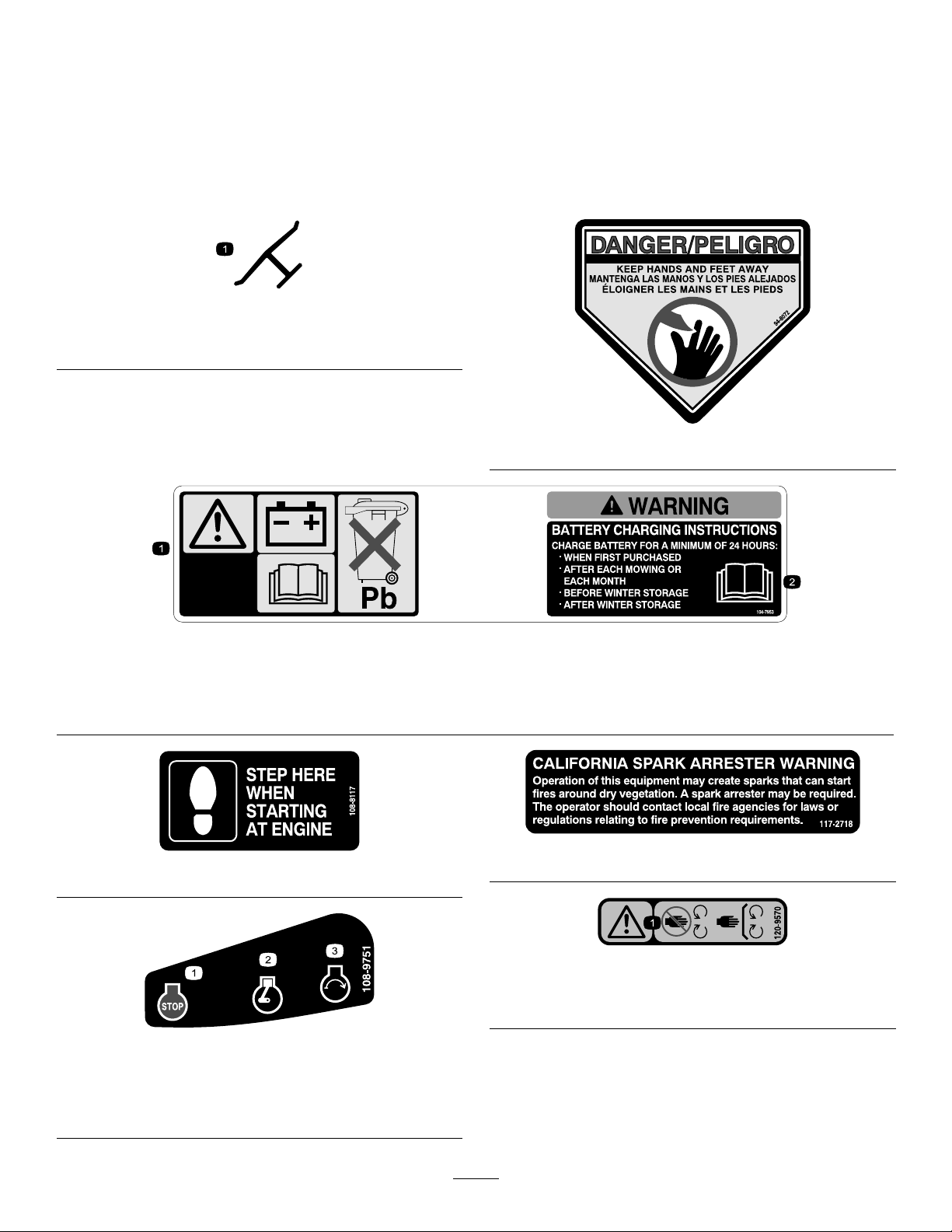
104-7953
Electric-startmodelonly
1.Warning—readtheOperator'sManualforinformationonchargingthebattery;containslead;donotdiscard.
2.ReadtheOperator'sManual.
108-8117
1.Warning—stayawayfrommovingparts,keepallguards
andshieldsinplace.
108-9751
Electric-startmodelonly
117-2718
120-9570
1.Engine—stop3.Engine—start
2.Engine—run
4
Page 5
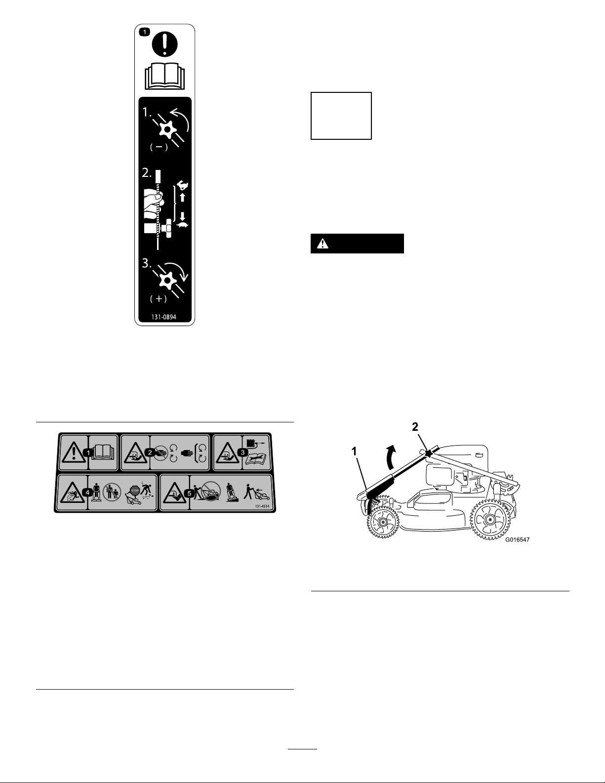
131-0894
1
G016547
2
TractionAdjustment
1.Attention;readtheOperator'sManual—1)Loosenthe
knobbyturningitcounterclockwise;2)Pullthecable(s)
awayfromtheenginetodecreasethetraction,orpush
thecable(s)towardtheenginetoincreasethetraction;3)
Tightentheknobbyturningitclockwise.
Setup
Important:Removeanddiscardtheprotectiveplastic
sheetthatcoverstheengine.
1
AssemblingtheHandle
NoPartsRequired
Procedure
WARNING
Assemblingandunfoldingthehandleimproperly
candamagethecables,causinganunsafeoperating
condition.
•Donotdamagethecableswhenunfoldingthe
handle.
•Ifacableisdamaged,contactanAuthorized
ServiceDealer.
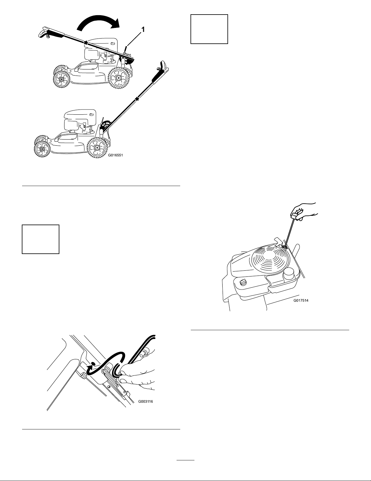
1.Rotatetheupperhandlesothatitneststogetherwith
thelowerhandle(Figure3),andtightenbothknobson
thehandletolocktheupperhandleinplace(Figure4).
131–4514
1.Warning—readtheOperator'sManual.
2.Cutting/dismembermenthazardofhandorfoot,mower
blade—stayawayfrommovingparts;keepallguardsand
shieldsinplace.
3.Cutting/dismembermenthazardofhandorfoot,mower
blade—disconnectthespark-plugwireandreadthe
instructionsbeforeservicingorperformingmaintenance.
4.Thrownobjecthazard—keepbystandersasafedistance
fromthemachine;stoptheenginebeforeleavingthe
operatingposition;pickupanydebrisbeforemowing.
5.Cutting/dismembermenthazardofhandorfoot,mower
blade—donotoperateupanddownslopes;operatesideto
sideonslopes;lookbehindyouwhenbackingup.
1.Upperhandle
Figure3
2.Knob(2)
5
Page 6
1
G016551
3
G017514
FillingtheEnginewithOil
NoPartsRequired
Procedure
Figure4
1.Handle-locklever
2.Releasethehandle-locklever(Figure4).
3.Pullthehandlerearwardandlockitintoposition
(Figure4).
2
InstallingtheBlade-Control Bar
Important:Yourmachine
theengine.Beforestartingtheengine,lltheengine
withoil.
Max.ll:0.59L(20oz),type:SAE30detergentoilwithan
APIserviceclassicationofSF,SG,SH,SJ,SL,orhigher.
Note:Whenthecrankcaseisempty,pourabout3/4of
thecrankcasecapacityofoilinthecrankcase,thendothe
following:
1.Movethemachinetoalevelsurface.
2.Removethedipstickbyrotatingthecap
counterclockwiseandpullingitout(Figure6).
does not
comewithoilin
NoPartsRequired
Procedure
Installtheblade-controlbarintotheupperhandle(Figure5).
Figure5
Figure6
3.Wipethedipstickcleanwithacleancloth.
4.Insertthedipstickfullyintotheoil-lltube,then
removethedipstick.
5.Readtheoillevelonthedipstick(Figure6).
6
Page 7
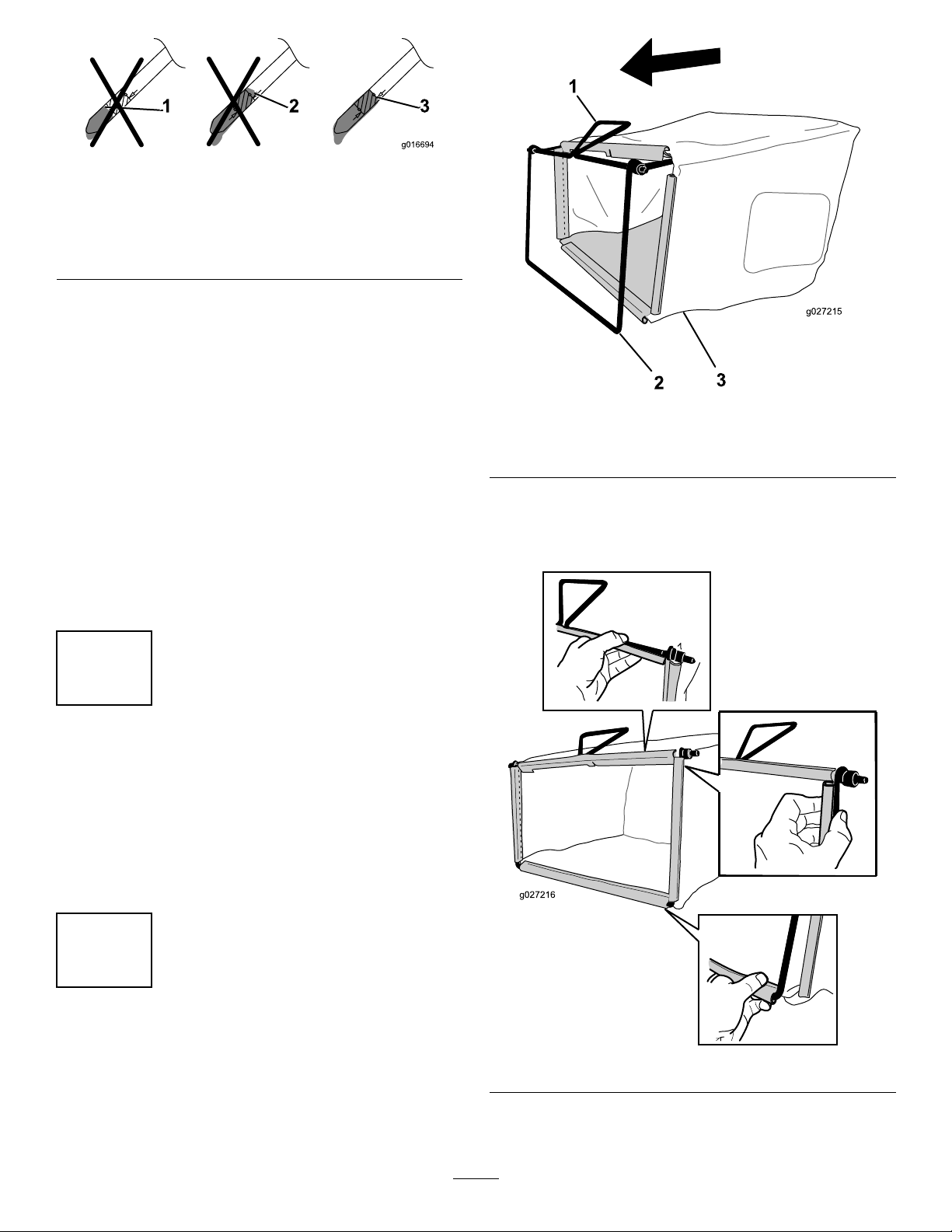
Figure7
1
2
3
g027215
g027216
1.Theoillevelistoolow;
addoiltothecrankcase.
2.Theoillevelistoohigh;
removeoilfromthe
crankcase.
•Iftheoillevelistoolow,slowlypourasmall
amountofoilintotheoil-lltube,wait3minutes,
andrepeatsteps3through5untiltheoillevelon
thedipstickiscorrectasshowninFigure7.
•Iftheoillevelistoohigh,draintheexcessoiluntil
youobtainthecorrectoillevelonthedipstick.To
draintheexcessoil,refertoChangingtheEngine
Oil(page17).
Important:Iftheoillevelinthecrankcaseistoo
lowortoohighandyouruntheengine,youmay
damagetheengine.
6.Installthedipsticksecurely.
Important:
operating hour s
toChangingtheEngineOil(page17).
Change the engine oil after the r st 5
;changeityearlythereafter.Refer
3.Theoilleveliscorrect.
Figure8
1.Handle
2.Frame
Note:Donotslipthebagoverthehandle(Figure8).
2.Hookthebottomchannelofthebagontothebottom
oftheframe(Figure9).
3.Grassbag
4
ChargingtheBattery
NoPartsRequired
Procedure
Electric-startmodelonly
RefertoChargingtheBattery(page18).
5
AssemblingtheGrassBag
NoPartsRequired
Procedure
1.SlipthegrassbagovertheframeasshowninFigure8.
Figure9
3.Hookthetopandsidechannelsofthebagontothetop
andsidesoftheframe,respectively(Figure9).
7
Page 8
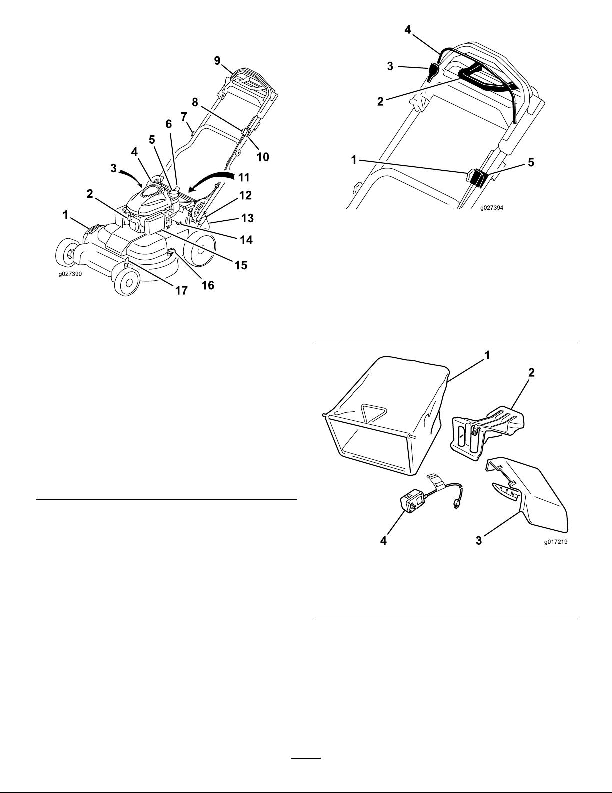
ProductOverview
2
14
1
13
3
4
5
6
7
8
9
10
11
12
g027390
15
16
17
2
1
3
4
5
g027394
g017219
1
2
34
Figure11
Upperhandle
Figure10
1.Side-dischargedeector
2.Sparkplug11.Battery(electric-start
3.Oilll/dipstick(notshown)
4.Recoil-starthandle
5.Fuel-tankcap14.Fuse
6.Handle-locklever
7.Handleknob(2)
8.Adjustmentknobforthe
self-propeldrive
9.Upperhandle
10.Ignitionswitch
(electric-startmodelonly)
ortoggleswitch(standard
modelonly)
modelonly;notshown)
12.Rearcutting-heightlever
13.Rear-dischargedeector
15.Airlter
16.Washoutport
17.Frontcutting-heightlever
1.Adjustmentknobforthe
self-propeldrive
2.Traction-assisthandle5.Ignitionswitch
3.Blade-control-barlock
4.Blade-controlbar
(electric-startmodelonly)
ortoggleswitch(standard
modelonly)
1.Grassbag3.Side-dischargechute
2.Rear-dischargeplug
(installed)
Figure12
4.Batterycharger
(electric-startmodelonly)
8
Page 9
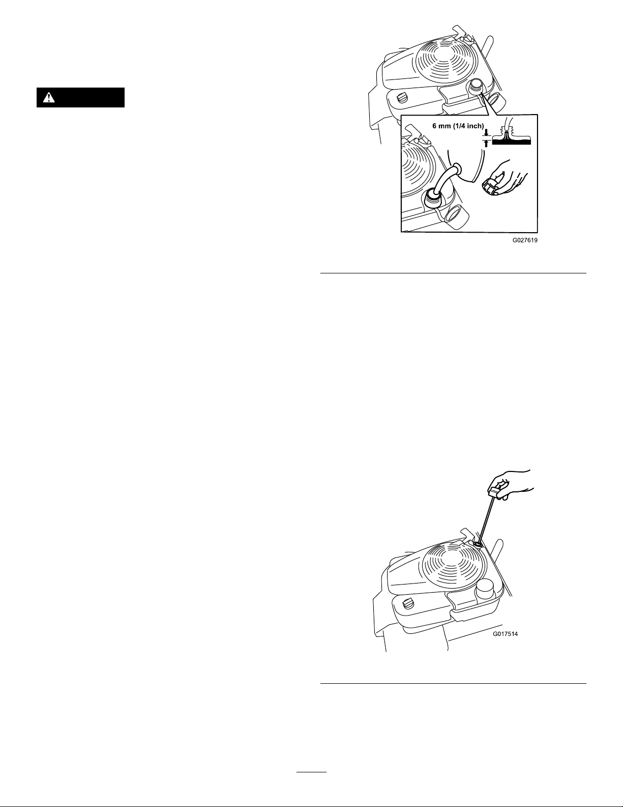
Operation
6 mm (1/4 inch)
G027619
G017514
FillingtheFuelTank
DANGER
Gasolineisextremelyammableandexplosive.A
reorexplosionfromgasolinecanburnyouand
others.
•Topreventastaticchargefromignitingthe
gasoline,placethecontainerand/ormachine
directlyonthegroundbeforelling,notina
vehicleoronanobject.
•Fillthetankoutdoorswhentheengineiscold.
Wipeupspills.
•Donothandlegasolinewhensmokingoraround
anopenameorsparks.
Figure13
•Storegasolineinanapprovedfuelcontainer,out
ofthereachofchildren.
•Forbestresults,useonlyclean,fresh,unleadedgasoline
withanoctaneratingof87orhigher((R+M)/2rating
method).
•Oxygenatedfuelwithupto10%ethanolor15%MTBE
byvolumeisacceptable.
•Donotuseethanolblendsofgasoline,suchasE15
orE85,withmorethan10%ethanolbyvolume.
Performanceproblemsand/orenginedamagemayresult,
whichmaynotbecoveredunderwarranty.
•Donotusegasolinecontainingmethanol.
•Donotstorefueleitherinthefueltankorinfuel
containersoverthewinterunlessfuelstabilizerhasbeen
addedtothefuel.
•Donotaddoiltogasoline.
Important:Toreducestartingproblems,addfuel
stabilizertothefuelallseason,mixingitwithgasoline
lessthan30daysold.
2.Fillthefueltank,leavingatleast6mm(1/4inch)from
thebottomoftheneckemptytoallowthegasoline
roomtoexpand(Figure13).
3.Installthefuel-tankcapandtightenitsecurelybyhand.
CheckingtheEngine-OilLevel
ServiceInterval:Beforeeachuseordaily
Note:Max.ll:0.59L(20oz),type:SAE30detergent
oilwithanAPIserviceclassicationofSF ,SG,SH,SJ,SL,
orhigher.
1.Movethemachinetoalevelsurface.
2.Removethedipstick(Figure14).
1.Cleanaroundthefuel-tankcap,andremovethecap
fromthetank(Figure13).
Figure14
3.Wipethedipstickcleanwithacleancloth.
4.Insertthedipstickfullyintotheoil-lltube,then
removethedipstick.
5.Readtheoillevelonthedipstick(Figure15).
9
Page 10

Figure15
1
2
3
4
5
6
7
G017634
1
2
3
4
5
6
7
G017635
1.Theoillevelistoolow;
addoiltothecrankcase.
2.Theoillevelistoohigh;
removeoilfromthe
crankcase.
3.Theoilleveliscorrect.
•Iftheoillevelistoolow,slowlypourasmall
amountofoilintotheoil-lltube,wait3minutes,
andrepeatsteps3through5untiltheoillevelis
correctasshowninFigure15.
•Iftheoillevelistoohigh,draintheexcessoiluntil
youobtainthecorrectoillevelonthedipstick.To
draintheexcessoil,refertoChangingtheEngine
Oil(page17).
Important:Iftheoillevelinthecrankcaseistoo
lowortoohighandyouruntheengine,youmay
damagetheengine.
6.Installthedipsticksecurely.
AdjustingtheCuttingHeight
WARNING
Figure16
Frontcutting-heightlever
1.A:10.8cm(4-1/4inches)5.E:5.7cm(2-1/4inches)
2.B:9.5cm(3-3/4inches)6.F:4.4cm(1-3/4inches)
3.C:8.3cm(3-1/4inches)7.G:3.2cm(1-1/4inches)
4.D:7.0cm(2-3/4inches)
Adjustingthecuttingheightmaybringyouinto
contactwiththemovingblade,causingserious
injury.
•Stoptheengineandwaitforallmovingparts
tostop.
•Donotputyourngersunderthehousingwhen
adjustingthecuttingheight.
Adjustthecuttingheightasdesired;refertoFigure14and
Figure15.
Note:T oraisethemachine,movethefrontandrear
cutting-heightleversforward;tolowerthemachine,movethe
cutting-heightleversrearward.Setthefrontandrearwheels
tothesameheightunlessspecialcircumstancesrequire
otherwise;refertoOperatingTips(page15).
Figure17
Rearcutting-heightlever
1.A:10.8cm(4-1/4inches)5.E:5.7cm(2-1/4inches)
2.B:9.5cm(3-3/4inches)6.F:4.4cm(1-3/4inches)
3.C:8.3cm(3-1/4inches)7.G:3.2cm(1-1/4inches)
4.D:7.0cm(2-3/4inches)
10
Page 11

AdjustingtheHandleHeight
2
G016488
3
1
G017516
G017595
Youcanraiseorlowerthehandletoapositionmore
comfortableforyou.
1.Liftthehandleslightlyandpullthehandle-locklever
rearwardtodisengagethehandle-lockpins(Figure18).
Figure18
1.Handle-locklever3.Notches
2.Handle-lockpin(2)
2.Rotatethehandleandalignthedesirednotchinthe
handlebrackettothehandle-lockpins;refertoFigure
18.
3.Releasethehandle-locklevertosecurethehandlein
place.
StartingtheEngine
StandardModel
Figure19
•Recoil-StartHandle:
1.TurntheignitionkeytotheRunposition(Figure
19).
2.Pulltherecoilhandleslowlytotherearuntilyou
feelresistance,thenpullsharply .Allowtheropeto
returntotheengineslowly.
UsingtheSelf-PropelDrive
Tooperatetheself-propeldrive,simplywalkwithyourhands
ontheupperhandleandyourelbowsatyoursides,andthe
machinewillautomaticallykeeppacewithyou(Figure20).
Note:Youcanself-propelthemachinewiththeblades
engagedordisengaged.
Pulltherecoilhandleslowlyuntilyoufeelresistance,thenpull
itsharply.Allowtheropetoreturntotheengineslowly.
Note:Ifthemachinedoesnotstartafterseveralattempts,
contactanAuthorizedServiceDealer.
Electric-startModel
Youcanstarttheengineonanelectric-startmodelbyusing
eithertheignitionkeyortherecoil-starthandle.
•IgnitionKey:
TurnandholdtheignitionkeytotheStartposition
(Figure19);whentheenginestarts,releasethekey.
Important:Donotattempttostarttheenginewith
theblade-controlbarengaged;otherwise,youmay
blowthefuse.
Note:DonotholdtheignitionkeyintheStartposition
forlongerthan5secondstopreventburningoutthe
startermotor.
Figure20
Note:Usethetraction-assisthandleinsituationswhenyou
needmorecontrolthanyouhavewiththeself-propeldrive
alone.
11
Page 12

StoppingtheEngine
G017636
G017517
g016484
1
2
g016485
StandardModel
Pressthetoggleswitch(Figure21)totheStoppositionand
holdituntiltheenginestops.
Figure21
1.Toggleswitch
Electric-startModel
Figure23
1.Blade-controlbarlock2.Blade-controlbar
2.Slowlypulltheblade-controlbarbacktothehandle
(Figure23).
3.Holdtheblade-controlbaragainstthehandle(Figure
24).
1.TurnthekeytotheOffposition(Figure22).
Figure22
2.Whentheenginestops,removetheignitionkeyand
takeitwithyouwhenyouleavethemachine.
EngagingtheBlade
Whenyoustartyourengine,thebladedoesnotturn.You
mustengagethebladetomow.
Figure24
DisengagingtheBlade
Releasetheblade-controlbar(Figure25).
Figure25
Important:Whenyoureleasetheblade-controlbar,
thebladeshouldstopwithin3seconds.Ifitdoesnot
stopproperly,stopusingyourmachineimmediatelyand
contactanAuthorizedServiceDealer.
1.Pulltheblade-control-barlockbacktotheblade-control
bar(Figure23).
12
Page 13

CheckingtheBlade-Stop
1
2
G016490
3
RecyclingtheClippings
SystemOperation
ServiceInterval:Beforeeachuseordaily
Checkthatthebladesstopwithin3secondsofreleasingthe
blade-controlbar.
UsingtheGrassBag
Youcanusethegrassbagtochecktheblade-stopsystem.
1.Removetherear-dischargeplug.
2.Installtheemptygrassbagonthemachine.
3.Starttheengine.
4.Engagetheblade.
Note:Thebagshouldbegintoinate,indicatingthat
thebladesarerotating.
5.Whilewatchingthebag,releasetheblade-controlbar.
Note:Ifthebagdoesnotdeatewithin3secondsof
releasingtheblade-controlbar,theblade-stopsystem
maybedeterioratingand,ifignored,couldresultin
anunsafeoperatingcondition.Havethemachine
inspectedandservicedbyanAuthorizedService
Dealer.
6.Stoptheengineandwaitforallmovingpartstostop.
Thismachinecomesfromthefactoryreadytorecyclegrass
andleafclippingsbackintothelawn.T opreparethemachine
torecycle,dothefollowing:
•Iftheside-dischargechuteisonthemachine,removeit
andlowertheside-dischargedeector;refertoRemoving
theSide-DischargeChute(page15).
•Ifthegrassbagisonthemachine,removeit;referto
RemovingtheGrassBag(page14).
•Iftherear-dischargeplugisnotinstalled,gripitbythe
handle,raisethereardeector,andinsertitintothe
rear-dischargechuteuntilthelatchlocksintoplace;refer
toFigure26.
NotUsingtheGrassBag
1.Movethemachineontoapavedsurfaceinanon-windy
area.
2.Setall4wheelstothe89mm(3-1/2inch)cutting
heightsetting.
3.Takeahalfsheetofnewspaperandcrumpleitintoa
ballsmallenoughtogounderthemachinehousing
(about76mm(3inches)indiameter).
4.Placethenewspaperballabout13cm(5inches)in
frontofthemachine.
5.Starttheengine.
6.Engagetheblade.
7.Releasetheblade-controlbarandbegincountingout3
seconds.
8.Onthecountof3,pushthemachinequicklyforward
overthenewspaper.
9.Stoptheengineandwaitforallmovingpartstostop.
10.Gotothefrontofthemachineandcheckthe
newspaperball.
Note:Ifthenewspaperballdidnotgounderthe
machine,repeatsteps4through10.
11.Ifthenewspaperisunravelledorshredded,theblades
didnotstopproperly ,whichcouldresultinanunsafe
operatingcondition.ContactanAuthorizedService
Dealer.
Figure26
1.Reardeector
2.Inserttherear-discharge
plug
3.Therear-dischargeplug
installed
WARNING
Ensurethattherear-dischargeplugisinplace
beforeyourecycletheclippings.Neverengagethe
bladeswithouteithertherear-dischargeplugorthe
grassbaginstalled.
BaggingtheClippings
Usethegrassbagwhenyouwanttocollectgrassandleaf
clippingsfromthelawn.
WARNING
Aworngrassbagcouldallowsmallstonesand
othersimilardebristobethrowntowardyouor
bystanders,resultinginseriouspersonalinjuryor
death.
Checkthegrassbagfrequently.Ifitisdamaged,
installanewTororeplacementbag.
13
Page 14

Iftheside-dischargechuteisonthemower,removeitbefore
1
2
G017408
3
G016513
1
2
G017521
1
2
baggingtheclippings;refertoRemovingtheSide-Discharge
Chute(page15).
Side-Dischargingthe Clippings
InstallingtheGrassBag
1.Raiseandholdupthereardeector(Figure27).
Figure27
1.Reardeector
2.Rear-dischargeplug
2.Removetherear-dischargeplugbypullingdownonthe
latchwithyourthumbandpullingtheplugoutfrom
themachine(Figure27).
3.Installthebagrodintothenotchesatthebaseofthe
handleandrockthebagbackandforthtoensurethat
therodisseatedatthebottomofbothnotches;refer
toFigure28.
3.Latch
Usethesidedischargeforcuttingverytallgrass.
Ifthebagisonthemachine,removeitandinsertthe
rear-dischargeplug;refertoRemovingtheGrassBag(page
14)beforeside-dischargingtheclippings.
Important:Ensurethattherear-dischargeplugisin
placebeforeyourecycletheclippings(Figure26).
WARNING
Thebladeissharp;contactingthebladecanresult
inseriouspersonalinjury.
Stoptheengineandwaitforallmovingpartstostop
beforeleavingtheoperatingposition.
InstallingtheSide-DischargeChute
1.Liftopentheside-dischargedeector(Figure29).
Figure29
1.Side-dischargedeector2.Side-dischargechute
1.Bagrod
4.Lowerthereardeectoruntilitrestsonthegrassbag.
Figure28
2.Notch(2)
2.Installtheside-dischargechuteasshowninFigure29
andFigure30,andclosethedeectorontothechute.
RemovingtheGrassBag
Toremovethebag,reversethestepsinInstallingtheGrass
Bag(page14).
14
Page 15

G017522
•Beawareofapotentialrehazardinverydryconditions,
followalllocalrewarnings,andkeepthemachinefree
ofdrygrassandleafdebris.
•Alternatethemowingdirection.Thishelpsdispersethe
clippingsoverthelawnforevenfertilization.
•Ifthenishedlawnappearanceisunsatisfactory,try1
ormoreofthefollowing:
–Replacethebladeorhaveitsharpened.
–Walkataslowerpacewhilemowing.
Figure30
RemovingtheSide-DischargeChute
Toremovetheside-dischargechute,reversethestepsin
InstallingtheSide-DischargeChute(page14).
OperatingTips
GeneralMowingTips
•Cleartheareaofsticks,stones,wire,branches,andother
debristhatthebladecouldhit.
•Avoidstrikingsolidobjectswiththeblade.Never
deliberatelymowoveranyobject.
•Ifthemachinestrikesanobjectorstartstovibrate,
immediatelystoptheengine,disconnectthewirefrom
thesparkplug,andexaminethemachinefordamage.
•Forbestperformance,installanewbladebeforethe
cuttingseasonbegins.
•ReplacethebladewhennecessarywithaToro
replacementblade.
–Raisethecuttingheightonyourmachine.
–Cutthegrassmorefrequently .
–Overlapcuttingswathsinsteadofcuttingafullswath
witheachpass.
–Setthecuttingheightonthefrontwheelsonenotch
lowerthantherearwheels.Forexample,setthefront
wheelsat51mm(2-inches)andtherearwheelsat64
mm(2-1/2inches).
CuttingLeaves
•Aftercuttingthelawn,ensurethathalfofthelawnshows
throughthecutleafcover.Youmayneedtomakemore
thanasinglepassovertheleaves.
•Iftherearemorethan13cm(5inches)ofleavesonthe
lawn,setthefrontcuttingheight1or2notcheshigher
thantherearcuttingheight.
•Slowdownyourmowingspeedifthemachinedoesnot
cuttheleavesnelyenough.
CuttingGrass
•Cutonlyaboutathirdofthegrassbladeatatime.Donot
cutbelowthe51mm(2-inch)settingunlessthegrassis
sparseoritislatefallwhengrassgrowthbeginstoslow
down.RefertoAdjustingtheCuttingHeight(page10).
•Whencuttinggrassover15cm(6inches)tall,mowatthe
highestcuttingheightsettingandwalkslower;thenmow
againatalowersettingforthebestlawnappearance.If
thegrassistoolong,themachinemayplugandcause
theenginetostall.
•Mowonlydrygrassorleaves.Wetgrassandleavestend
toclumpontheyardandcancausethemachinetoplug
ortheenginetostall.
WARNING
Wetgrassorleavescancauseseriousinjuryif
youslipandcontacttheblade.Mowonlyindry
conditions.
15
Page 16

Maintenance
G017520
1
Note:Determinetheleftandrightsidesofthemachinefromthenormaloperatingposition.
RecommendedMaintenanceSchedule(s)
MaintenanceService
Interval
Aftertherst5hours
Beforeeachuseordaily
Every25hours
Every50hours
Yearly
Yearlyorbeforestorage
Important:Refertoyourengineowner'smanualforadditionalmaintenanceprocedures.
PreparingforMaintenance
1.Stoptheengineandwaitforallmovingpartstostop.
2.Disconnectthespark-plugwirefromthesparkplug
(Figure31).
MaintenanceProcedure
•Changetheengineoil.
•Checktheengine-oillevel.
•Checktheblade-brake-clutchoperation.
•Checktheaircleanerandcleanorreplaceit,ifnecessary.
•Checkthecuttingblades.
•Cleangrassclippingsanddirtfromunderthemachine.
•Chargethebattery(electric-startmodelonly).
•Changetheengineoil.
•Servicetheblade-drivesystem.
•Servicetheairlter;replaceitmorefrequentlyindustyoperatingconditions.
•Changetheengineoil.
•Servicethecuttingblades.
•Refertoyourengineoperator'smanualforanyadditionalyearlymaintenance
procedures.
•Chargethebattery(electric-startmodelonly).
•Emptythefueltankbeforerepairsasdirectedandbeforeyearlystorage.
handfuelpumptoremovethefuel.Alwaystipthe
machineontoitsside,withthedipstickdown.
WARNING
Tippingthemachinemaycausethefueltoleak.
Gasolineisammableandexplosiveandcancause
personalinjury.
Figure31
1.Spark-plugwire
3.Afterperformingthemaintenanceprocedure(s),
connectthespark-plugwiretothesparkplug.
Important:Beforetippingthemachinetochange
theoilorreplacetheblade,allowthefueltankto
rundrythroughnormalusage.Ifyoumusttip
themachinepriortorunningoutoffuel,usea
Runtheenginedryorremovethegasolinewitha
handpump;neversiphon.
16
Page 17

ServicingtheAirFilter
G017216
2
1
3
4
G017281
ServiceInterval:Beforeeachuseordaily
Yearly
1.Loosenthefastenerandremovetheair-ltercover
(Figure32).
Figure32
3.Disconnectthewirefromthesparkplug.Referto
PreparingforMaintenance(page16).
4.Tipthemachineontoitsside,withthedipstickdown,
untiltheupperhandlerestsontheground.
5.Setanoil-drainpanunderthedipstick.
6.Removethedipstickanddraintheusedoilintothe
oil-drainpan(Figure33).
Figure33
7.Afterdrainingtheusedoil,returnthemachinetothe
operatingposition.
1.Cover
2.Fastener4.Base
3.Filter
8.Pourabout3/4ofthecrankcasecapacityofoilinthe
crankcase.
Note:Max.ll:0.59L(20oz),type:SAE30
2.Removeandinspectthelter.
•Ifthelterisdamagedoriswetwithoilorfuel,
replaceit.
•Ifthelterisdirty,tapitonahardsurfaceseveral
timesorblowthedebrisoutwardfromtheinterior
detergentoilwithanAPIserviceclassicationofSF ,
SG,SH,SJ,SL,orhigher.
9.Waitabout3minutesfortheoiltosettleinthe
crankcase.
10.Wipethedipstickcleanwithacleancloth.
ofthelterusingcompressedairatlessthan207
kPa(30psi).
11.Insertthedipstickfullyintotheoil-lltube,then
removethedipstick.
Note:Donotbrushorblowdirtfromtheoutside
ofthelter;eitherforcesdirtintothebers.
12.Readtheoillevelonthedipstick(Figure34).
3.Cleantheair-lterbodyandcoverusingadamprag.
Keepdirtawayfromtheairopening .
4.Installthelterontothebase.
5.Installthecoverandscrewthefastenerdownsecurely.
ChangingtheEngineOil
ServiceInterval:Aftertherst5hours
Every50hours
Yearly
Note:Runtheengineafewminutesbeforechangingthe
oiltowarmit.W armoilowsbetterandcarriesmore
contaminants.
1.Ensurethatthefueltankcontainslittleornofuelso
thatfueldoesnotleakoutwhenyoutipthemachine
ontoitsside.
2.Movethemachinetoalevelsurface.
1.Theoillevelistoolow;
addoiltothecrankcase.
2.Theoillevelistoohigh;
removeoilfromthe
crankcase.
•Iftheoillevelistoolow,slowlypourasmall
amountofoilintotheoil-lltube,wait3minutes,
andrepeatsteps10through12untiltheoillevelis
correctasshowninFigure34.
•Iftheoillevelistoohigh,draintheexcessoiluntil
youobtainthecorrectoillevelonthedipstick.
Figure34
3.Theoilleveliscorrect.
17
Page 18

Important:Iftheoillevelinthecrankcaseistoo
G017518
G020856
1
lowortoohighandyouruntheengine,youmay
damagetheengine.
13.Installthedipsticksecurely.
14.Recycletheusedoilproperly .
Note:Whenthebatterynolongerholdsacharge,
recyclethelead-acidbatteryaccordingtolocalcodes.
ReplacingtheFuse
Electric-startmodelonly
ChargingtheBattery
ServiceInterval:Every25hours
Yearlyorbeforestorage
Electric-startmodelonly
WARNING
Batteryposts,terminals,andrelatedaccessories
containleadandleadcompounds,chemicals
knowntotheStateofCaliforniatocausecancerand
reproductiveharm.
the batter y .
Chargethebatteryfor24hoursinitially,thenmonthly(every
25starts)orasneeded.Alwaysusethechargerinasheltered
area,andchargethebatteryatroomtemperature(about22°
C,or70°F)wheneverpossible.
Note:Themachineisequippedwithanalternatorcharging
system.
1.Connectthechargertothewireharness,whichis
locatedbelowtheignitionkey(Figure35).
W ash y our hands after handling
Ifthebatterydoesnotchargeortheenginedoesnotturn
withtheelectricstarter,thefusemaybeblown;replaceitwith
a40-ampplug-intypefuse.
Important:Youcannotstartthemachinewiththe
electricstarterorchargethebatteryunlessaworking
fuseisinstalled.
1.Openthesealedfuseholderandreplacethefuse
(Figure36).
Figure36
Figure35
2.Plugthechargerintoawalloutlet.
Note:Yourbatterychargermayhavea2-colorLED
displaythatindicatesthefollowingstatesofcharging:
•Aredlightindicatesthatthechargerischarging
thebattery.
•Agreenlightindicatesthatthechargerisfully
chargedorisdisconnectedfromthebattery.
•Aashinglightthatalternatesbetweenredand
greenindicatesthatthebatteryisnearlyfully
charged.Thisstatelastsonlyafewminutesuntil
thebatteryisfullycharged.
1.Fuseholder
2.Closethecovertothefuseholder,andensurethatit
issealedtightly.
ReplacingtheBattery
Electric-startmodelonly
RemovingtheOldBattery
1.ContactanAuthorizedT oroPartsDealertoobtaina
replacementbattery.
2.Removethebeltcover;refertostep1ofServicingthe
Blade-driveSystem(page20).
3.Removetherear-dischargeplug.
4.Movethehandletotheverticalposition.
5.Removethe4smallboltsthatholdtherear-deector
andhandle-lockleverassemblyinplace.
6.Foldthehandleallthewayforward.
7.Removetherear-deectorandhandle-locklever
assembly(Figure36).
18
Page 19

G017523
1
Figure37
g027709
1.Rear-deectorandhandle-lockleverassembly
8.Removethecoverfromthebattery.
AdjustingtheSelf-PropelDrive
Wheneveryouinstallanewself-propelcableorifthe
self-propeldriveisoutofadjustment,adjusttheself-propel
drive.
1.Turntheadjustmentknobcounterclockwisetoloosen
thecableadjustment(Figure38).
9.Disconnecttheleadsfromthebattery.
10.Removeandbatteryandrecycleit.
Note:Recyclethebatteryaccordingtoyourstateand
localregulations.
InstallingtheNewBattery
1.Cleanthebattery-holdingareaonthemachinehousing.
2.Setthenewbatteryinplaceonthemachinehousing.
3.Connecttheleadstothenewbattery.
Note:Ensurethatyouconnecttheblack(negative)
wiretothenegative(-)terminalandthered(positive)
wiretothepositive(+)terminal.
4.Installthecoverontothebattery.
Note:Ensurethatthecovertsproperlyoverthe
wiringharness.
5.Installtherear-deectorandhandle-lockleverassembly
ontothemachine.
6.Raisethehandletotheverticalposition.
Figure38
1.Handle(leftside)3.Self-propel-drivecable
2.Adjustmentknob
2.Adjustthetensiononthecable(Figure38)bypullingit
backorpushingitforwardandholdingthatposition.
Note:Pushthecabletowardtheenginetoincrease
thetraction;pullthecableawayfromtheengineto
decreasethetraction.
3.Turntheadjustmentknobclockwisetotightenthe
cableadjustment.
Note:Tightentheknobrmlybyhand.
7.Securetheshroudwiththe4smallboltsthatyou
removedinstep5ofRemovingtheOldBattery(page
18).
8.Installtherear-dischargeplug.
9.Returnthehandletotheoperatingposition.
19
Page 20

ServicingtheBlade-Drive
G016491
1
2
g017221
2
1
3
4
5
6
1
G025927
ServicingtheCuttingBlades
System
ServiceInterval:Every50hours
1.Removetheblade-drivesystemcover(Figure39).
Figure39
1.Bolts
2.Brushorblowoutdebrisfromtheinsideoftheshield
andaroundalltheparts.
3.Holda0.25mm(0.010-inch)feelergauge,apieceof
paper,oranotecardagainstthewallandslideitdown
behindthebelttensionspring.
Note:Ifthereisavisiblegapbetweenthegaugeand
thespring,tightentheadjustingboltandthenutuntil
thepaperbarelyslidesfreelyinandoutofthegap
(Figure40).
2.Cover
ServiceInterval:Yearly
Important:
blades pr oper l y .
areuncomfortableperformingthisprocedure,contact
anAuthorizedServiceDealer.
Examinethebladesforsharpnessandanywearordamage
wheneveryourunoutofgasoline.Ifthebladeedgesare
dullornicked,havethemsharpenedorreplacetheblades.
Ifabladeisworn,bent,damagedorcracked,replaceit
immediatelywithagenuineTororeplacementblade.
Y ou will need a torque wr ench to install the
Ifyoudonothaveatorquewrenchor
DANGER
Awornordamagedbladecanbreak,andapiece
ofthebladecouldbethrowntowardtheoperator
orabystander,resultinginseriouspersonalinjury
ordeath.
•Inspectthebladesperiodicallyforwearor
damage.
•Replaceawornordamagedblade.
Note:Maintainsharpbladesthroughoutthecuttingseason,
becausesharpbladescutcleanlywithouttearingorshredding
thegrassblades.
PreparingtoServicetheCuttingBlades
1.Lockthehandleintheverticalposition(Figure41);
refertoAdjustingtheHandleHeight(page11).
Figure40
1.Belt-tensionspring4.Adjustingnut
2.Adjustingbolt5.Blade-drivebelt
3.Gap
Important:Donotovertightentheadjustingbolt.
Thiscoulddamagetheblade-drivebelt.
4.Installtheblade-drivesystemcoverthatyoupreviously
removed.
6.Wall
Figure41
1.Handlelockedintheverticalposition
2.Tipthemachineontoitsside,withthedipstickdown,
untiltheupperhandlerestsontheground.
20
Page 21

WARNING
g017223
B
B
2
1
3
g016532
Thebladesaresharp;contactingabladecould
resultinseriouspersonalinjury.
•Disconnectthewirefromthesparkplug .
•Weargloveswhenservicingtheblade.
InspectingtheBlades
ServiceInterval:Beforeeachuseordaily
1.Inspectthecuttingedges(Figure42).Iftheedgesare
notsharporhavenicks,removethebladesandhave
themsharpenedorreplacethem.
CheckingforBentBlades
1.RotatethebladestothepositionshowninFigure43.
Figure43
Figure42
1.Cuttingedge3.Wear/slotforming
2.Curvedarea4.Crack
2.Inspectthebladesthemselves,especiallythecurved
area(Figure42).Ifyounoticeanydamage,wear,ora
slotforminginthisarea,immediatelyreplaceitwith
anewblade.
DANGER
Ifyouallowabladetowear,aslotwillform
betweenthesailandatpartoftheblade.
Eventuallyapieceoftheblademaybreak
offandbethrownfromunderthehousing,
possiblyresultinginseriousinjurytoyouor
bystanders.
•Inspectthebladeperiodicallyforwearor
damage.
•Nevertrytostraightenabladethatisbent
orweldabrokenorcrackedblade.
•Replaceawornordamagedblade.
3.Checkforbentblades;refertoCheckingforBent
Blades(page21).
1.Frontofcuttingdeck3.Measurefromthecutting
edgetoasmooth,level
surface
2.MeasureatlocationsA
andB
2.Measurefromalevelsurfacetothecuttingedges
atlocationsAandB(Figure43),andrecordboth
dimensions.
3.Rotatethebladessothattheiroppositeendsareat
locationsAandB(Figure43).
4.Repeatthemeasurementsinstep2andrecordthem.
Note:IfthedifferencebetweenthedimensionsAand
Bobtainedinsteps2and4exceeds1/8in(3mm),
thebladeisbentandyouwillneedtoreplaceit.Refer
toRemovingtheBlades(page22)andInstallingthe
Blades(page22).
WARNING
Abladethatisbentordamagedcouldbreakapart
andcouldseriouslyinjureorkillyouorbystanders.
•Alwaysreplaceabentordamagedbladewith
anewblade.
•Neverleorcreatesharpnotchesintheedges
orsurfacesofablade.
21
Page 22

RemovingtheBlades
G016530
1
2
3
4
g016537
InstallingtheBlades
Replacethebladeswhenthemachinehitsasolidobjector
whenabladeisoutofbalanceorbent.Useonlygenuine
Tororeplacementblades.
1.Useablockofwoodtoholdeachbladesteadyandturn
thebladeboltcounterclockwiseasshowninFigure44.
Figure44
1.Installtherstbladesothatitishorizontal,alongwith
allmountinghardwareasshowninFigure45.
Note:Tightentheboltwithyourngers.
Important:Positionthecurvedendsoftheblades
topointtowardthemachinehousing.Besureto
nesttheraisedareasoneachbladedriverwiththe
recessesintheheadofitscorrespondingspindle,
andthepinsontheothersideofeachbladedriver
withtheholesinitscorrespondingblade.
2.Steadyeachbladewithaboardandturnthebladebolt
clockwisewithatorquewrenchasshowninFigure46;
torquethebladeboltto82N-m(60ft-lb).
Important:Abolttorquedto82N-m(60ft-lb)is
verytight.Putyourweightbehindthewrenchand
tightentheboltsecurely.Thisboltisverydifcult
toovertighten.
2.RemoveeachbladeasshowninFigure45.
Figure45
1.Spindle(2)3.Blade(2)
2.Bladedriver(2)4.Bladebolt(2)
Figure46
3.Rotatetheinstalledblade1/4turnuntilitisvertical,
andinstalltheotherbladeinthesamemannerasthe
rst(refertostep1).
Note:Thebladesshouldbeperpendicular,forming
aninverted“T”asshowninFigure47.
3.Inspectthepinsonthebladedriversforwearand
damage.
22
Page 23

1
G016536
Figure47
1.Blade(2)
4.Tightenthesecondblade;refertostep2.
5.Rotatethebladesbyhandafull360°turntoensure
thattheydonottouch.
Note:Ifthebladestoucheachother,theyarenot
mountedcorrectly.Repeatsteps1through3,untilthe
bladesnolongertoucheachother.
WARNING
Incorrectlyinstallingthebladescoulddamagethe
machineorcauseaninjurytotheoperatororto
bystanders.
CleaningundertheMachine
ServiceInterval:Beforeeachuseordaily
1.Movethemachinetoalevelsurface.
2.Stoptheengineandwaitforallmovingpartstostop
beforeleavingtheoperatingposition.
3.Lowerthemachinetoitslowestcutting-heightsetting.
RefertoAdjustingtheCuttingHeight(page10).
4.Attachahosetothewashouttting,andturnthewater
onhigh(Figure48).
Figure48
1.Washouttting3.O-ring
2.Hose
5.Starttheengine,engagetheblade-controllever,andlet
themachinerunfor1to3minutes.
6.Disengagetheblade-controllever,stoptheengine,and
waitforallmovingpartstostop.
7.Shutoffthewaterandremovethecouplingfromthe
washouttting.
Note:Ifthemachineisnotcleanafterasingle
washing,soakitandletitstandfor30minutes.Then
repeattheprocess.
8.Runthemachineagainandengagethebladesfor1to3
minutestoremovetheexcesswater.
4.Coupling
WARNING
Abrokenormissingwashoutttingcouldexpose
youandotherstothrownobjectsorbladecontact.
Contactwithabladeorthrowndebriscancause
injuryordeath.
Note:Spreadpetroleumjellyonthewashouttting
O-ringtomakethecouplingslideoneasierandprotect
theO-ring.
•Replaceabrokenormissingwashouttting
immediately,beforeusingthemachineagain.
•Neverputyourhandsorfeetunderthemachine
orthroughopeningsinthemachine.
23
Page 24

Storage
Storethemachineinacool,clean,dryplace.
GeneralInformation
1.Performtherecommendedannualmaintenance
procedures;refertoMaintenance(page16).
2.Cleanunderthemachinehousing;refertoCleaning
undertheMachine(page23).
3.Removechaff,dirt,andgrimefromtheexternalparts
oftheengine,theshrouding,andthetopofthe
machine.
PreparingtheEngine
1.Whiletheengineisstillwarm,changetheengineoil;
refertoChangingtheEngineOil(page17).
2.Removethesparkplug.
3.Usinganoilcan,addabout30ml(1oz),ofmotoroil
totheenginethroughthespark-plughole.
4.Slowlypullthestarterropeseveraltimestodistribute
oilthroughoutthecylinder.
5.Installthesparkplugbutdonotconnectthewireto
thesparkplug.Securethewiresothatitdoesnotcome
intocontactwiththesparkplug.
4.Checktheconditionoftheblades;refertoInspecting
theBlades(page21).
5.Servicetheairlter;refertoServicingtheAirFilter
(page17).
6.Tightenallnuts,bolts,andscrews.
7.Touchupallrustedorchippedpaintsurfaceswith
paintavailablefromanAuthorizedServiceDealer.
8.Chargethebatteryfor24hours,thenunplugthe
batterychargerandstorethemachineinanunheated
area.Ifyoumuststorethemachineinaheatedarea,
youmustchargethebatteryevery90days(electric-start
modelonly).
9.Foldthehandleforstorage;refertoAdjustingthe
HandleHeight(page11).
PreparingtheFuelSystem
WARNING
Gasolinecanvaporizeifyoustoreitoverlong
periodsoftimeandexplodeifitcomesintocontact
withanopename.
•Donotstoregasolineoverlongperiodsoftime.
RemovingtheMachinefrom Storage
1.Unfoldthehandle;refertoAdjustingtheHandle
Height(page11).
2.Checkandtightenallfasteners.
3.Removethesparkplugandspintheenginerapidly
usingthestartertoblowexcessoilfromthecylinder.
4.Inspectthesparkplugandreplaceitifitisdirty,worn,
orcracked;refertotheengineoperator’smanual.
5.Installthesparkplugandtightenittotherecommended
torqueof20N-m(180in-lb).
6.Performanyneededmaintenanceprocedures;referto
Maintenance(page16).
7.Checktheengineoillevel;refertoCheckingthe
Engine-OilLevel(page9).
8.Fillthefuelinthefueltankwithfreshgasoline;referto
FillingtheFuelTank(page9).
9.Chargethebattery(electric-startmodelonly);referto
ChargingtheBattery(page18).
10.Connectthewiretothesparkplug.
•Donotstorethemachinewithgasolineinthe
fueltankorthecarburetorinanenclosurewith
anopename.(Forexample,afurnaceora
waterheaterpilotlight.)
•Allowtheenginetocoolbeforestoringitinany
enclosure.
Onthelastrefuelingoftheyear,addfuelstabilizertothefuel
asdirectedbytheenginemanufacturer.Emptythefueltank
whenmowingthelasttimebeforestoringthemachine.
1.Runthemachineuntiltheenginestopsfromrunning
outoffuel.
2.Starttheengineagain.
3.Allowtheenginetorununtilitstops.Whenyoucan
nolongerstarttheengine,itissufcientlydry.
24
Page 25

Notes:
25
Page 26

Notes:
26
Page 27

Notes:
27
Page 28

TheToroTotalCoverageGuarantee
A3-Y earFullWarranty(45DayLimitedWarrantyforCommercialUse)
TheT oroGTSStartingGuarantee
A3-YearFullWarranty(NotApplicableforCommercialUse)
TimeMaster
WalkPowerMowers
ConditionsandProductsCovered
TheToroCompanyanditsafliate,T oroWarrantyCompany,pursuantto
anagreementbetweenthem,jointlypromisetorepairtheT oroProduct
listedbelowifusedforresidentialpurposes*;ifitisdefectiveinmaterials
orworkmanshiporifitstopsfunctioningduetothefailureofacomponent;
oriftheT oroGTS(GuaranteedtoStart)enginewillnotstartontherstor
secondpull,providedtheroutinemaintenancerequiredintheOperator's
Manualhavebeenperformed.
Thiswarrantycoversthecostofpartsandlabor,butyoumustpay
transportationcosts.
Thefollowingtimeperiodsapplyfromthedateofpurchase:
ProductsWarrantyPeriod
TimeMasterMowerand
Attachments
GTS(GuaranteedtoStart)3-yearfullwarranty
Battery
3-yearfullwarranty
1-yearfullwarranty
LimitedWarrantyforCommercialUse*
TheseT oroProductsusedforcommercial,institutional,orrentaluse,
arewarrantedfor45daysagainstdefectsinmaterialsorworkmanship.
Componentsfailingduetonormalweararenotcoveredbythiswarranty.
TheT oroGTS(GuaranteedtoStart)StartingGuaranteedoesnotapply
whentheproductisusedcommercially*.
InstructionsforObtainingWarrantyService
IfyouthinkthatyourT oroProductcontainsadefectinmaterialsor
workmanship,orifanormal,able-bodiedadultcannolongerstartyour
product'sengineinoneortwopulls,followthisprocedure:
1.ContactanyAuthorizedT oroServiceDealertoarrangeserviceat
theirdealership.T olocateadealerconvenienttoyou,accessourweb
siteatwww.T oro.com.Y oumayalsocallthenumberslistedinitem#3
tousethe24-hourT oroDealerlocatorsystem.
2.Bringtheproductandyourproofofpurchase(salesreceipt)tothe
ServiceDealer.Thedealerwilldiagnosetheproblemanddetermineif
itiscoveredunderwarranty.
3.IfforanyreasonyouaredissatisedwiththeServiceDealer’s
analysisorwiththeassistanceprovided,contactusat:
CustomerCareDepartment,RLCDivision
TheT oroCompany
811 1LyndaleAvenueSouth
Bloomington,MN55420-1 196
Tollfreeat866-214-9807(U.S.customers)
Tollfreeat866-214-9808(Canadiancustomers)
OwnerResponsibilities
YoumustmaintainyourT oroProductbyfollowingthemaintenance
proceduresdescribedintheOperator'sManual.Suchroutinemaintenance,
whetherperformedbyadealerorbyyou,isatyourexpense.
ItemsandConditionsNotCovered
Thereisnootherexpresswarrantyexceptforspecialemissionsystem
coverageandenginewarrantycoverageonsomeproducts.Thisexpress
warrantydoesnotcoverthefollowing:
•Costofregularmaintenanceserviceorparts,suchaslters,fuel,
lubricants,oilchanges,sparkplugs,airltersbladesharpeningorworn
blades,cable/linkageadjustments,orbrakeandclutchadjustments
•Componentsfailingduetonormalwear
•Anyproductorpartwhichhasbeenalteredormisusedorneglected
andrequiresreplacementorrepairduetoaccidentsorlackofproper
maintenance
•Pickupanddeliverycharges
•RepairsorattemptedrepairsbyanyoneotherthananAuthorizedT oro
ServiceDealer
•Repairsnecessaryduetofailuretofollowrecommendedfuel
procedure(consultOperator'sManualformoredetails)
–Removingcontaminantsfromthefuelsystemisnotcovered
–Useofoldfuel(morethanonemonthold)orfuelwhichcontains
morethan10%ethanolormorethat15%MTBE
–Failuretodrainthefuelsystempriortoanyperiodofnon-use
overonemonth
•Repairsoradjustmentstocorrectstartingdifcultiesduetothe
following:
–Failuretofollowpropermaintenanceproceduresorrecommended
fuelprocedure
–Rotarymowerbladestrikinganobject
•Specialoperationalconditionswherestartingmayrequiremorethan
twopulls:
–Firsttimestartsafterextendedperiodofnon-useoverthree
monthsorseasonalstorage
–Cooltemperaturestartssuchasthosefoundinearlyspringand
lateautumn
–Improperstartingprocedures-ifyouarehavingdifcultystarting
yourunit,pleasechecktheOperator'sManualtoensurethat
youareusingthecorrectstartingprocedures.Thiscansavean
unnecessaryvisittoanAuthorizedT oroServiceDealer.
GeneralConditions
AllrepairscoveredbythesewarrantiesmustbeperformedbyanAuthorized
ToroServiceDealerusingT oro-approvedreplacementparts.Repairbyan
AuthorizedT oroServiceDealerisyoursoleremedyunderthiswarranty.
NeitherTheToroCompanynorT oroWarrantyCompanyisliablefor
indirect,incidental,orconsequentialdamagesinconnectionwiththe
useoftheToroProductscoveredbythesewarranties,includingany
costorexpenseofprovidingsubstituteequipmentorserviceduring
reasonableperiodsofmalfunctionornon-usependingcompletionof
repairsunderthesewarranties.
Somestatesdonotallowexclusionsofincidentalorconsequential
damages,sotheaboveexclusionsmaynotapplytoyou.
Thiswarrantygivesyouspeciclegalrights,andyoumayalsohaveother
rightswhichvaryfromstatetostate.
CountriesOtherthantheUnitedStatesorCanada
CustomerswhohavepurchasedT oroproductsexportedfromtheUnitedStatesorCanadashouldcontacttheirT oroDistributor(Dealer)toobtain
guaranteepoliciesforyourcountry,province,orstate.IfforanyreasonyouaredissatisedwithyourDistributor'sserviceorhavedifcultyobtaining
guaranteeinformation,contacttheT oroimporter.Ifallotherremediesfail,youmaycontactusatT oroWarrantyCompany.
AustralianConsumerLaw:AustraliancustomerswillnddetailsrelatingtotheAustralianConsumerLaweitherinsidetheboxoratyourlocalT oro
Dealer.
*Residentialpurposesmeansuseoftheproductonthesamelotasyourhome.Useatmorethanonelocation,orinstitutionalorrentaluse,isconsidered
commercialuse,andthecommercialusewarrantywouldapply.
374-0283RevC
 Loading...