

Page 1

TORO/LAWNBOY BATTERY & ELECTRIC POWERED MOWER SERVICE MANUAL
Table Of Contents – Page 1 of 1
INTRODUCTION
SPECIFICATIONS
120 VOLT MODELS
BATTERY MODELS
MOTOR
EUROPEAN MODELS
METRIC TORQUE AND BLADE TIP SPEED
ASSEMBLY REQUIREMENTS
SPECIAL TOOLS
SAFETY INFORMATION
120 VOLT MODELS
BATTERY POWERED MODELS
OPERATIONAL TIPS (120 VOLT MODELS)
BEFORE STARTING
MAINTENANCE
OPERATIONAL TIPS (24/36 VOLT MODELS)
CHARGING
LED CHARGING LIGHTS CHART
STORAGE
BATTERY POWER STATUS
OPERATION
KEY
STARTING/STOPPING INSTRUCTIONS
MOWING TIPS
MAINTENANCE
TESTING ELECTRICAL COMPONENTS
120 VOLT MODELS
BATTERY POWERED MODELS
BLADE STOPPING SYSTEMS
DISASSEMBLY & REASSEMBLY
DISASSEMBLY — BATTERY MODELS
TRANSFORMER REPLACEMENT — BATTERY MODELS
BATTERY REPLACEMENT
BLADE REPLACEMENT — 120 VOLT MODELS
BLADE BRAKE — 120 VOLT MODELS
BRAKE DRUM
120 VOLT MOTOR REPLACEMENT
REPLACING BLADE SPINDLE OR SPINDLE BEARINGS
CABLE REPLACEMENT — ALL MODELS
CABLE ADJUSTMENT
BELT REPLACEMENT — 120 VOLT MODELS
HIPOT TESTING
INTRODUCTION
HIPOT TESTER SAFETY RULES
TESTING THE OUTLET FOR GROUND
TESTING PROCEDURE
TESTING THE MOTOR
Page 2

Page 3

TABLE OF CONTENTS
Introduction . . . . . . . . . . . . . . . . . . . . . . . . . . . . . . . . . . . . . . . . . . . . . . . . . . . . . . . . . . . . . 1 - 1
Models Covered In This Manual . . . . . . . . . . . . . . . . . . . . . . . . . . . . . . . . . . . . . . . . 1 - 1
North American Models . . . . . . . . . . . . . . . . . . . . . . . . . . . . . . . . . . . . . . . . . . . . 1 - 1
International Models . . . . . . . . . . . . . . . . . . . . . . . . . . . . . . . . . . . . . . . . . . . . . . 1 - 1
Model/Serial Number Location . . . . . . . . . . . . . . . . . . . . . . . . . . . . . . . . . . . . . . . . . 1 - 1
Specifications. . . . . . . . . . . . . . . . . . . . . . . . . . . . . . . . . . . . . . . . . . . . . . . . . . . . . . . . . . . . 1 - 2
120 Volt Models . . . . . . . . . . . . . . . . . . . . . . . . . . . . . . . . . . . . . . . . . . . . . . . . . . . . .1 - 2
Battery Models . . . . . . . . . . . . . . . . . . . . . . . . . . . . . . . . . . . . . . . . . . . . . . . . . . . . . .1 - 2
Motor. . . . . . . . . . . . . . . . . . . . . . . . . . . . . . . . . . . . . . . . . . . . . . . . . . . . . . . . . . . . . 1 - 3
European Models . . . . . . . . . . . . . . . . . . . . . . . . . . . . . . . . . . . . . . . . . . . . . . . . . . . 1 - 3
Metric Torque and Blade Tip Speed . . . . . . . . . . . . . . . . . . . . . . . . . . . . . . . . . . . . . .1 - 3
Assembly Requirements . . . . . . . . . . . . . . . . . . . . . . . . . . . . . . . . . . . . . . . . . . . . . 1 - 4
Special Tools . . . . . . . . . . . . . . . . . . . . . . . . . . . . . . . . . . . . . . . . . . . . . . . . . . . . . . 1 - 4
Safety Information . . . . . . . . . . . . . . . . . . . . . . . . . . . . . . . . . . . . . . . . . . . . . . . . . . . . . . . . 2 - 1
120 Volt Models . . . . . . . . . . . . . . . . . . . . . . . . . . . . . . . . . . . . . . . . . . . . . . . . . . . . 2 - 1
Important Safety Instructions . . . . . . . . . . . . . . . . . . . . . . . . . . . . . . . . . . . . . . . . 2 - 1
Safe Operating Practices . . . . . . . . . . . . . . . . . . . . . . . . . . . . . . . . . . . . . . . . . . . 2 - 1
General Operation . . . . . . . . . . . . . . . . . . . . . . . . . . . . . . . . . . . . . . . . . . . . . . . . 2 - 1
While Operating . . . . . . . . . . . . . . . . . . . . . . . . . . . . . . . . . . . . . . . . . . . . . . . . . . 2 - 2
Maintenance And Storage . . . . . . . . . . . . . . . . . . . . . . . . . . . . . . . . . . . . . . . . . . 2 - 3
Safety and Instruction Decals . . . . . . . . . . . . . . . . . . . . . . . . . . . . . . . . . . . . . . . 2 - 5
Battery Powered Models . . . . . . . . . . . . . . . . . . . . . . . . . . . . . . . . . . . . . . . . . . . . . 2 - 7
Introduction . . . . . . . . . . . . . . . . . . . . . . . . . . . . . . . . . . . . . . . . . . . . . . . . . . . . . 2 - 7
Important Safety Instructions . . . . . . . . . . . . . . . . . . . . . . . . . . . . . . . . . . . . . . . . 2 - 7
Safe Operating Practices . . . . . . . . . . . . . . . . . . . . . . . . . . . . . . . . . . . . . . . . . . . 2 - 7
General Operation . . . . . . . . . . . . . . . . . . . . . . . . . . . . . . . . . . . . . . . . . . . . . . . . 2 - 7
While Operating . . . . . . . . . . . . . . . . . . . . . . . . . . . . . . . . . . . . . . . . . . . . . . . . . . 2 - 8
Maintenance And Storage . . . . . . . . . . . . . . . . . . . . . . . . . . . . . . . . . . . . . . . . . . 2 - 9
Sound Emissions . . . . . . . . . . . . . . . . . . . . . . . . . . . . . . . . . . . . . . . . . . . . . . . . 2 - 11
Vibration Level . . . . . . . . . . . . . . . . . . . . . . . . . . . . . . . . . . . . . . . . . . . . . . . . . . 2 - 11
Symbol Glossary . . . . . . . . . . . . . . . . . . . . . . . . . . . . . . . . . . . . . . . . . . . . . . . . 2 - 11
Operational Tips (120 Volt Models) . . . . . . . . . . . . . . . . . . . . . . . . . . . . . . . . . . . . . . . . . . . 3 - 1
Before Starting . . . . . . . . . . . . . . . . . . . . . . . . . . . . . . . . . . . . . . . . . . . . . . . . . . . . . 3 - 1
Secure Extension Cord. . . . . . . . . . . . . . . . . . . . . . . . . . . . . . . . . . . . . . . . . . . . . 3 - 1
Plan Your Mowing Pattern . . . . . . . . . . . . . . . . . . . . . . . . . . . . . . . . . . . . . . . . . . 3 - 2
Maintenance . . . . . . . . . . . . . . . . . . . . . . . . . . . . . . . . . . . . . . . . . . . . . . . . . . . . . . . 3 - 2
Cleaning . . . . . . . . . . . . . . . . . . . . . . . . . . . . . . . . . . . . . . . . . . . . . . . . . . . . . . . . 3 - 2
After Every Use . . . . . . . . . . . . . . . . . . . . . . . . . . . . . . . . . . . . . . . . . . . . . . . . . . 3 - 3
Once A Year . . . . . . . . . . . . . . . . . . . . . . . . . . . . . . . . . . . . . . . . . . . . . . . . . . . . . 3 - 3
Blade . . . . . . . . . . . . . . . . . . . . . . . . . . . . . . . . . . . . . . . . . . . . . . . . . . . . . . . . . . 3 - 3
Servicing Double-Insulated Mower . . . . . . . . . . . . . . . . . . . . . . . . . . . . . . . . . . . 3 - 5
Storage . . . . . . . . . . . . . . . . . . . . . . . . . . . . . . . . . . . . . . . . . . . . . . . . . . . . . . . . 3 - 5
Carefree Mower Service Manual i
Page 4

TABLE OF CONTENTS
Operational Tips (24/36 Volt Models). . . . . . . . . . . . . . . . . . . . . . . . . . . . . . . . . . . . . . . . . . .3 - 7
Charging . . . . . . . . . . . . . . . . . . . . . . . . . . . . . . . . . . . . . . . . . . . . . . . . . . . . . . . . . . .3 - 7
LED Charging Lights Chart . . . . . . . . . . . . . . . . . . . . . . . . . . . . . . . . . . . . . . . . . . . . .3 - 8
Storage . . . . . . . . . . . . . . . . . . . . . . . . . . . . . . . . . . . . . . . . . . . . . . . . . . . . . . . . . . . 3 - 9
Battery Power Status . . . . . . . . . . . . . . . . . . . . . . . . . . . . . . . . . . . . . . . . . . . . . . . . .3 - 9
Operation. . . . . . . . . . . . . . . . . . . . . . . . . . . . . . . . . . . . . . . . . . . . . . . . . . . . . . . . . . 3 - 9
Key . . . . . . . . . . . . . . . . . . . . . . . . . . . . . . . . . . . . . . . . . . . . . . . . . . . . . . . . . . . . . 3 - 10
Starting/Stopping Instructions . . . . . . . . . . . . . . . . . . . . . . . . . . . . . . . . . . . . . . . . . .3 - 10
To Start Motor . . . . . . . . . . . . . . . . . . . . . . . . . . . . . . . . . . . . . . . . . . . . . . . . . . .3 - 10
To Stop Motor . . . . . . . . . . . . . . . . . . . . . . . . . . . . . . . . . . . . . . . . . . . . . . . . . . . 3 - 11
Circuit Breaker . . . . . . . . . . . . . . . . . . . . . . . . . . . . . . . . . . . . . . . . . . . . . . . . . . .3 - 11
Mowing Tips . . . . . . . . . . . . . . . . . . . . . . . . . . . . . . . . . . . . . . . . . . . . . . . . . . . . . . .3 - 11
Battery Run Time . . . . . . . . . . . . . . . . . . . . . . . . . . . . . . . . . . . . . . . . . . . . . . . . 3 - 11
General Mulching Tips . . . . . . . . . . . . . . . . . . . . . . . . . . . . . . . . . . . . . . . . . . . . .3 - 12
Cutting Leaves . . . . . . . . . . . . . . . . . . . . . . . . . . . . . . . . . . . . . . . . . . . . . . . . . . .3 - 12
Adjusting Height-of-Cut . . . . . . . . . . . . . . . . . . . . . . . . . . . . . . . . . . . . . . . . . . . . 3 - 13
Maintenance . . . . . . . . . . . . . . . . . . . . . . . . . . . . . . . . . . . . . . . . . . . . . . . . . . . . . . .3 - 13
Cleaning . . . . . . . . . . . . . . . . . . . . . . . . . . . . . . . . . . . . . . . . . . . . . . . . . . . . . . . .3 - 14
After Every Use . . . . . . . . . . . . . . . . . . . . . . . . . . . . . . . . . . . . . . . . . . . . . . . . . . 3 - 14
Once A Year . . . . . . . . . . . . . . . . . . . . . . . . . . . . . . . . . . . . . . . . . . . . . . . . . . . . 3 - 14
Blade . . . . . . . . . . . . . . . . . . . . . . . . . . . . . . . . . . . . . . . . . . . . . . . . . . . . . . . . . .3 - 14
Testing Electrical Components. . . . . . . . . . . . . . . . . . . . . . . . . . . . . . . . . . . . . . . . . . . . . . . .4 - 1
120 Volt Models. . . . . . . . . . . . . . . . . . . . . . . . . . . . . . . . . . . . . . . . . . . . . . . . . . . . . 4 - 1
Safety Information . . . . . . . . . . . . . . . . . . . . . . . . . . . . . . . . . . . . . . . . . . . . . . . . .4 - 1
Wiring Diagrams . . . . . . . . . . . . . . . . . . . . . . . . . . . . . . . . . . . . . . . . . . . . . . . . . . .4 - 1
120 Electrical System Testing. . . . . . . . . . . . . . . . . . . . . . . . . . . . . . . . . . . . . . . . 4 - 1
Battery Powered Models . . . . . . . . . . . . . . . . . . . . . . . . . . . . . . . . . . . . . . . . . . . . . . 4 - 2
Motor Testing . . . . . . . . . . . . . . . . . . . . . . . . . . . . . . . . . . . . . . . . . . . . . . . . . . . . .4 - 2
Solenoid Testing . . . . . . . . . . . . . . . . . . . . . . . . . . . . . . . . . . . . . . . . . . . . . . . . . .4 - 2
Testing Batteries . . . . . . . . . . . . . . . . . . . . . . . . . . . . . . . . . . . . . . . . . . . . . . . . . . 4 - 3
Charger Testing . . . . . . . . . . . . . . . . . . . . . . . . . . . . . . . . . . . . . . . . . . . . . . . . . . .4 - 4
Charging Indicator Lights . . . . . . . . . . . . . . . . . . . . . . . . . . . . . . . . . . . . . . . . . . . 4 - 4
Flashing Yellow Charging Indicator . . . . . . . . . . . . . . . . . . . . . . . . . . . . . . . . . . . .4 - 4
Flashing Red Charging Indicator . . . . . . . . . . . . . . . . . . . . . . . . . . . . . . . . . . . . . .4 - 5
Steady Red Charging Indicator . . . . . . . . . . . . . . . . . . . . . . . . . . . . . . . . . . . . . . .4 - 5
Steady Yellow Charging Indicator . . . . . . . . . . . . . . . . . . . . . . . . . . . . . . . . . . . . .4 - 5
Steady Green Charging Indicator . . . . . . . . . . . . . . . . . . . . . . . . . . . . . . . . . . . . . 4 - 6
Charge Remaining Indicator Lights. . . . . . . . . . . . . . . . . . . . . . . . . . . . . . . . . . . . 4 - 6
Transformer Testing . . . . . . . . . . . . . . . . . . . . . . . . . . . . . . . . . . . . . . . . . . . . . . . 4 - 7
US & Canadian Models. . . . . . . . . . . . . . . . . . . . . . . . . . . . . . . . . . . . . . . . . . . . 4 - 7
European, U.K., & Swiss Models . . . . . . . . . . . . . . . . . . . . . . . . . . . . . . . . . . . .4 - 7
ii Carefree Mower Service Manual
Page 5

TABLE OF CONTENTS
Switch Testing . . . . . . . . . . . . . . . . . . . . . . . . . . . . . . . . . . . . . . . . . . . . . . . . . . . . . 4 - 8
Switch Testing (battery powered models). . . . . . . . . . . . . . . . . . . . . . . . . . . . . . . 4 - 8
Wire Harness . . . . . . . . . . . . . . . . . . . . . . . . . . . . . . . . . . . . . . . . . . . . . . . . . . . . 4 - 8
Testing Safety Key Terminals . . . . . . . . . . . . . . . . . . . . . . . . . . . . . . . . . . . . . . . 4 - 8
Circuit Breaker Testing . . . . . . . . . . . . . . . . . . . . . . . . . . . . . . . . . . . . . . . . . . . . 4 - 8
Blade Stopping Systems . . . . . . . . . . . . . . . . . . . . . . . . . . . . . . . . . . . . . . . . . . . . . . . . . . . 5 - 1
120 Volt Blade Stopping System . . . . . . . . . . . . . . . . . . . . . . . . . . . . . . . . . . . . . . . 5 - 1
Battery Mower Systems . . . . . . . . . . . . . . . . . . . . . . . . . . . . . . . . . . . . . . . . . . . . . . 5 - 1
Disassembly & Reassembly . . . . . . . . . . . . . . . . . . . . . . . . . . . . . . . . . . . . . . . . . . . . . . . . 6 - 1
Disassembly — Battery Models . . . . . . . . . . . . . . . . . . . . . . . . . . . . . . . . . . . . . . . . 6 - 1
Transformer Replacement — Battery Models . . . . . . . . . . . . . . . . . . . . . . . . . . . . . 6 - 1
Battery Replacement . . . . . . . . . . . . . . . . . . . . . . . . . . . . . . . . . . . . . . . . . . . . . . . . 6 - 1
Blade Replacement — 120 Volt Models . . . . . . . . . . . . . . . . . . . . . . . . . . . . . . . . . 6 - 1
Blade Brake — 120 Volt Models . . . . . . . . . . . . . . . . . . . . . . . . . . . . . . . . . . . . . . . 6 - 2
Brake Drum . . . . . . . . . . . . . . . . . . . . . . . . . . . . . . . . . . . . . . . . . . . . . . . . . . . . . . . 6 - 2
120 Volt Motor Replacement . . . . . . . . . . . . . . . . . . . . . . . . . . . . . . . . . . . . . . . . . . 6 - 2
Replacing Blade Spindle or Spindle Bearings . . . . . . . . . . . . . . . . . . . . . . . . . . . . . 6 - 3
Cable Replacement — All Models . . . . . . . . . . . . . . . . . . . . . . . . . . . . . . . . . . . . . . 6 - 3
Cable Adjustment . . . . . . . . . . . . . . . . . . . . . . . . . . . . . . . . . . . . . . . . . . . . . . . . . . . 6 - 3
Belt Replacement — 120 Volt Models . . . . . . . . . . . . . . . . . . . . . . . . . . . . . . . . . . . 6 - 3
Hipot Testing . . . . . . . . . . . . . . . . . . . . . . . . . . . . . . . . . . . . . . . . . . . . . . . . . . . . . . . . . . . . .7 - 1
Introduction . . . . . . . . . . . . . . . . . . . . . . . . . . . . . . . . . . . . . . . . . . . . . . . . . . . . . . . . .7 - 1
Hipot Tester Safety Rules . . . . . . . . . . . . . . . . . . . . . . . . . . . . . . . . . . . . . . . . . . . . . .7 - 1
Testing the Outlet for Ground . . . . . . . . . . . . . . . . . . . . . . . . . . . . . . . . . . . . . . . . . . .7 - 1
Testing Procedure. . . . . . . . . . . . . . . . . . . . . . . . . . . . . . . . . . . . . . . . . . . . . . . . . . . .7 - 1
Testing the Motor . . . . . . . . . . . . . . . . . . . . . . . . . . . . . . . . . . . . . . . . . . . . . . . . . . . .7 - 3
Carefree Mower Service Manual iii
Page 6

PREFACE
ABOUT THIS MANUAL
This manual was written expressly for the Toro and Lawn-Boy brand electric and battery
powered mowers. The Toro Company has made every effort to make the information in this
manual complete and correct.
This manual was written with the service technician in mind. The book contains material
covering mowers that operate on 120 volt alternating current (North America only), and battery
powered mowers that operate on 24 volt or 36 volt direct current.
We hope that you find this manual a valuable addition to your service shop. If you have
questions or comments regarding this manual, please contact us at the following address:
The Toro Company
Consumer Service Department
8111 Lyndale Avenue South
Bloomington, MN 55420-1196
The Toro Company reserves the right to change product specifications or this manual without
notice.
COPYRIGHT - ALL RIGHTS RESERVED
The Toro Company - 1999
Bloomington, MN 55420 - U.S.A.
Page 7
g
g
g
g
g
1
INTRODUCTION
Models Covered In This Manual
North American Models
Models covered by this manual. All are built on the
same 18” chassis. The only differences are in the
electrical systems.
Model No. Brand Power
10101 Lawn-Boy 120 vac
10120 & 10122 Lawn-Boy 24 vdc
10123 Lawn-Boy 36 vdc
20645
20646
20050
20647 & 20648
20652
20649 Toro 36 vdc
International Models
Toro 120 vac
Toro 24 vdc
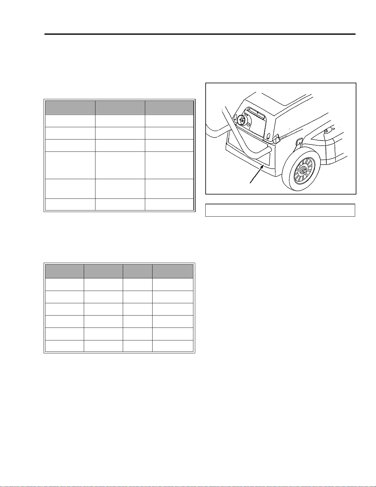
Model/Serial Number Location
On all battery or electric powered mowers, the model
and serial number is engraved in the lower rear of the
body or on a metal tag at this location (Figure 1).
A
ure 1
Fi
(A) Model and Serial Number
Fig-1
These models are offered in Europe, U.K., and
Switzerland. These models use 230 volt AC to char
the batteries. The electrical portion of these models
will be covered in a separate section.
Model No. Brand Power Sold In
10701 Lawn-Boy 24 vdc Europe
21040 Toro 24 vdc Europe
10702 Lawn-Boy 24 vdc U.K.
21042 Toro 24 vdc U.K.
10703 Lawn-Boy 24 vdc Switzerland
21043 Toro 24 vdc Switzerland
NOTE: This manual may apply to model numbers
other than those in the tables above. Differences
between models, other than volta
different ori
equipment. For example, a model may include a side
dischar
inal packaging or different standard
e chute, a bagger, both, or neither.
e, may include
e
Carefree Mower Service Manual 1- 1
Page 8

SPECIFICATIONS
g
gging
Specifications (120 Volt Models)
Item Specification
Width of Cut
Motor
RPM
Blade Tip Speed
@ 3600 rpm
Weight
Standard
Function
Options
Compliance
18” (46 cm)
Universal wound 120 volt motor. Motor rated at 12 amps continuous duty.
Motor 20,500 with step down belt drive ratio 5.8-1. Blade speed at 20,500 fps is 3,534 rpm.
16,493 fps
38 lbs. net dry.
The mowers come with mulchin
Side ba
Conforms to UL #1447, CSA #C22.2 No. 147-M90, ANSI B71.1 and CPSC requirements.
kit.
capability and a side discharge deflector.
Specifications (Battery Models)
These models are built on the same basic chassis as the 120 volt models. However, the major differences will be
due to the different style and quantity of batteries. This will affect the weight as well as the wiring, motor, and
solenoid. All batteries are of the sealed lead acid type.
Model Brand Battery Operating Volts Weight/Net Dry Run Time
10120 Lawn-Boy 4 - 6 volt (12.5 ah) 24 vdc 58 lbs. 45 - 60 min.
10122 Lawn-Boy 4 - 6 volt (12.5 ah) 24 vdc 60 lbs. 45 - 60 min.
10123 Lawn-Boy 6 - 6 volt (12.5 ah) 36 vdc 68 lbs. 65 - 90 min.
20052 Toro 4 - 6 volt (12.5 ah) 24 vdc 60 lbs. 45 - 60 min.
20647 Toro 2 - 12 volt (17 ah) 24 vdc 70 lbs. 60 - 90 min.
20648 Toro 4 - 6 volt (12.5 ah) 24 vdc 60 lbs. 45 - 60 min.
20649 Toro 3 - 12 volt (17 ah) 36 vdc 84 lbs. 90 - 120 min.
1 - 2 Carefree Mower Service Manual
Page 9

SPECIFICATIONS
Motor
24 Volt Models 36 Volt Models
Type 24 volt permanent magnet 36 volt permanent magnet
Speed 3750 ± 375 rpm 3600 ± 360 rpm
Torque 165 oz.-in. @ 3100 rpm 180 oz.-in. @ 2950 rpm
Rated Continuous Duty 22 amps 15 amps
No Load Amps 8 amps 4.5 amps
Blade Tip Speed 17,180 fps @ 3750 rpm 16,473 fps @ 3600 rpm
Compliance Conforms to UL #1447, CSA #C22.2 No. 147-M90, ANSI B71.1 and CPSC
requirements
Standard Function Mulchin
Options Side bagging kit
g and side discharging
European Models
Model No. Brand Battery Operating Volts Weight Run Time Sold In
21040 Toro 4/6 volt 24 vdc 27kg 45 - 60 min. Europe
21042 Toro 4/6 volt 24 vdc 27kg 45 - 60 min. U.K.
21043 Toro 4/6 volt 24 vdc 27kg 45 - 60 min. Switzerland
Charging - On board charging converts 230 volt AC line voltage to DC.
*Motor and blade speed specs same as North American models.
Metric Torque and Blade Tip Speeds
24 Volt 36 Volt
Motor Torque 1.165 Newton-Meter
1165 Newton-Millimeter
1.271 Newton-Meter
1271 Newton-Millimeter
Blade Tip Speed 5236.5 Meters/Minute @ 3750 rpm 5021 Meters/Minute @ 3600 rpm
Carefree Mower Service Manual 1- 3
Page 10

SPECIFICATIONS
Assembly Requirements
Item Assembly Information
Deck to liner screws 15 - 20 in. lbs. (17.3 - 23.0 kg cm)
Wheel bolts 180 - 240 in. lbs. (207 - 276 kg cm)
Motor to deck screws 80 - 85 in. lbs. (92 - 97 kg cm)
Spindle pulley nut (120 volt) 200 - 300 in. lbs. (230 - 345.5 kg cm)
Spindle to deck screws 80 - 85 in. lbs. (92 0 97 kg cm)
Blade bolt (battery models) 35 - 40 ft. lbs. (4.8 - 5.5 kg m)
Blade bolt (120 volt) 45 - 50 ft. lbs. (6.2 - 6.9 kg m)
Blade bolt/belleville washer cup side towards blade
Control cable bracket (battery models) Upper position
Control cable bracket (120 volt) Lower position
Special Tools
Most repairs can be made using normal hand tools. However, the use of a powered screwdriver will prove
invaluable.
A volt/ohmmeter is necessary for troubleshooting the electrical system. A good digital meter will simplify taking the
necessary readings.
120 VAC models will require high potential testing after making repairs to the electrical components.
1 - 4 Carefree Mower Service Manual
Page 11

g
g
g
g
g
g
2
SAFETY INFORMATION
120 Volt Models
IMPORTANT SAFETY INSTRUCTIONS
This machine meets or exceeds CPSC blade safety
requirements for walk-behind rotary mowers and
the B71.1 specifications of the American National
Standards Institute, in effect at time of production.
However, improper use or maintenance by the
operator or owner can result in injury. To reduce
the potential for injury, comply with these safety
instructions and always pay attention to the safety
alert symbol which means CAUTION,
WARNING or DANGER — "personal safety
instruction." Failure to comply with the instruction
may result in personal injury.
WARNING: To reduce the risk of fire, electric
shock, and personal injury when usin
lawn mowers, always follow these basic safety
precautions.
!
electric
READ ALL INSTRUCTIONS
BEFORE USING THIS MOWER
SAVE THESE INSTRUCTIONS
FOR FUTURE REFERENCE!
Safe Operating Practices
This product is capable of amputating hands and feet
and throwin
instructions to avoid serious injury or death.
This mower is desi
or, when equipped with a
rass. Any use for purposes other than these
could prove dan
objects. Always follow all safety
ned for cutting and mulching grass
rass bag, for catching cut
erous to user or bystanders.
2. The operator of the mower is responsible for
keeping everyone, especially children and pets,
away from area of operation. The operator is
responsible for accidents or hazards occurring to
other people or their property.
3. Thoroughly inspect area where mower will be
used and remove sticks, stones, wire, and debris
that could be picked up and thrown by mower.
Watch for foreign objects while mowing. Objects
struck by the lawn mower blade can cause severe
injuries to persons.
4. Wear long pants and substantial shoes. Do not
operate mower while wearing open-toed shoes,
jewelry, loose clothing or when barefoot. Use of
rubber gloves and footwear is recommended
when working outdoors.
5. Keep all guards, shields, safety devices, side
discharge chute or optional grass catcher in place.
Repair or replace damaged parts, including
decals. Never tamper with safety devices. Check
their proper operation regularly.
6. The motor and blade are designed to stop within 3
seconds after releasing the control bail. Ensure
that the control bail functions properly before each
use of mower. If the blade does not stop within 3
seconds, or if there is a grinding or scraping
metal-to-metal noise when the control bail is
released, contact your local Authorized Toro
Service Dealer for proper "On/Off" and blade
brake adjustment or replacement.
7. Before usin
the blades, blade fasteners and cutter assembly
are not worn or damaged. Replace worn or
damaged blades and fasteners in sets to preserve
balance.
g, always visually inspect to see that
General Operation
1. Read this manual carefully before operating the
mower. Become familiar with the controls and
proper use of the mower. Never allow children
under 16 years of age to operate the mower.
Never allow adults to operate mower without
proper instructions.
Carefree Mower Service Manual 2 - 1
8. Only use those accessories and attachments
designed to be used with this product. Use of any
accessory or attachment not designed for this
product may increase the risk of injury.
9. Ground Fault Circuit Interrupter (GFCI) protection
should be provided on the circuit(s) or outlet(s) to
be used for the lawn mower.
Receptacles are available having built-in GFCI
protection and may be used for this measure of
safety.
Page 12
SAFETY INFORMATION
g
WARNING:
10.
with an extension cord suitable for outdoor use,
such as SW-A, SOW-A, STW-A, STOW-A, SJWA, SJOW-A, SJTW-A, or SJTOW-A.
1 1. Extension Cord — Make sure your extension cord
set is in
cord, be sure to use one heavy enough to carry
the current your product will draw. Refer to
Extension Cord Chart, see page 3 - 1. An
undersized cord will cause a drop in line voltage
resulting in loss of power and overheating.
12. Properly connect extension cord to mower in order
to prevent disconnection of the cord (Figure 2).
To prevent electric shock, use only
good condition. When using an extension
Figure 3
Scan7-a
While Operating
1. Do not connect extension cord to mower until you
are ready to mow.
Figure 2
13. To reduce the risk of electric shock, this mower
has a polarized plug (one blade is wider than the
other) (Fi
polarized extension cord. The polarized extension
cord receptacle will fit onto the mower plug only
one way. If the extension cord receptacle does
not fit fully onto the mower plug, reverse the cord
receptacle. If the cord receptacle still does not fit,
obtain a correct polarized extension cord. A
polarized extension cord will require the use of a
polarized wall outlet. The extension cord plug will
fit into the polarized wall outlet only one way. If
the cord plug does not fit fully into the wall outlet,
reverse the cord plug. If the cord plug still does
not fit, contact a qualified electrician to install the
proper wall outlet. Do not change the mower plug,
extension cord receptacle, or extension cord plug
in any way.
ure 3) and will require the use of a
0663-002
2. Start the motor carefully according to instructions
and with feet well away from the blade.
3. Use Right Appliance — Do not use mower for any
job except that for which it is intended.
4. Stay Alert — Watch what you are doing. Do not
operate mower when tired or under the influence
of drugs, alcohol, or medication.
5. Be alert and turn mower off if children enter the
area.
6. Use extra care when approaching blind corners,
shrubs, trees, or other objects that may obscure
vision.
7. Do not mow near drop-offs, ditches, or
embankments. The operator could lose footin
balance.
8. Avoid dangerous environments. Never operate
mower in wet grass or damp locations. Do not
use mower in the rain.
9. Do not run motor indoors.
10. Do not operate mower in gaseous, explosive
atmospheres. Normal sparking of motor could
ignite fumes.
g or
2 - 2 Carefree Mower Service Manual
Page 13

SAFETY INFORMATION
11. Always maintain secure footing. Keep a firm grip
on the handle and walk; never run. Mow only in
daylight or in good artificial light.
12. Mow across the face of slopes; never up and
down. Use extreme caution when changing
direction on slopes. Do not mow excessively
steep slopes. Wear skid resistant shoes on
slopes.
13. Don't Overreach — Keep proper footing and
balance at all times.
14. Do not force the mower. It operates best and
safest at the rate for which it was designed.
15. Always wear safety glasses or eye shields during
operation to protect eyes from foreign objects that
may be thrown from the machine. (Regular
eyeglasses are not safety glasses.)
16. Always wear an approved dust mask when using
unit in dusty conditions.
17. Keep face, hands, and feet away from the mower
housing and cutter blade when the motor is
running. Blade can cause injury to hands and
feet. Stay behind the handle until the motor stops.
18. Use extreme caution when reversing or pulling the
mower toward you. Before and while moving
backwards, look behind and down for small
children.
19. Since the blade rotates for a few seconds after the
control bar is released, stay behind the handle
until all movin
20. After striking a foreign object or if mower vibrates
abnormally, stop motor and disconnect extension
cord. Check mower for damage and make all
repairs before using mower again. If major repairs
are ever needed or if assistance is desired,
contact your local Authorized Toro Service Dealer.
21. Do not operate mower if it has been dropped or
dama
ged in any way. Repair any damage before
operating mower.
22. Do not run the mower over the extension cord.
23. Inspect extension cord periodically and replace
cord if damaged.
g parts stop.
24. Don't abuse extension cord. Never pull mower by
cord or yank cord to disconnect it from receptacle.
Keep cord away from heat, oil, and sharp edges.
25. Stop the motor, wait for all moving parts to stop,
and disconnect extension cord from mower before
adjusting the height-of-cut.
26. Stop the motor when pushing the mower outside
the lawn area.
27. Stop the motor and disconnect extension cord
from mower before removing side discharge chute
or optional grass catcher.
28. Stop motor before leaving the operator's position
— behind the handle. Disconnect extension cord
from mower if mower will be unattended.
29. If mower must be lifted to be transported, stop
motor, stay behind the handle until all moving
parts stop and disconnect extension cord from
mower.
Maintenance And Storage
1. Perform only those maintenance instructions
described in this manual. If major repairs are ever
needed or if assistance is desired, contact your
local Authorized Toro Service Dealer.
2. Before mower is cleaned, inspected, serviced, or
adjusted, stop motor and wait for all movin
to stop. Disconnect extension cord from mower.
3. To ensure the mower is in safe operating
condition, frequently check and keep all nuts,
bolts, and screws tight. Ensure blade bolt is
tightened to 45-50 ft.lbs. (61-68 N·m).
4. Always keep a sharp blade on your mower. When
servicing blade, refer to blade maintenance
section for correct installation and servicing
procedures. Use identical replacement blades
only.
5. To reduce fire hazard, keep motor free of
excessive grass, leaves, and accumulations of
dirt.
6. This unit is provided with double insulation. Use
only identical replacement parts. See “Servicing
Double-Insulated Mower” on page 3 - 5.
g parts
Carefree Mower Service Manual 2 - 3
Page 14

SAFETY INFORMATION
7. When not in use, store mower indoors in a dry,
locked-up place out of the reach of children. Allow
motor to cool before storing in an enclosure.
8. Check optional grass catcher bag frequently for
wear or deterioration. Replace with a new bag
when worn or damaged for your protection.
9. At the time of manufacture, the mower conformed
to the safety standards in effect for rotary mowers.
To assure best performance and continued safety
certification of the mower, use
replacement parts and accessories. Replacement
parts and accessories made by other
manufacturers may result in non-conformance
with the safety standards, and that could be
dangerous.
SAVE THESE INSTRUCTIONS
FOR FUTURE REFERENCE!
genuine Toro
2 - 4 Carefree Mower Service Manual
Page 15
SAFETY INFORMATION
Safety and Instruction Decals
Safety decals and instructions are easily
visible to the operator and are located near
ON CONTROL PANEL ON MULCH PLUG ON MULCH PLUG
any area of potential danger. Replace any decal that
is damaged or lost.
ON MULCH PLUG
ON REAR OF MOWER UNDER COVER
ON REAR OF MOWER
(Part No. 94-3860)
Carefree Mower Service Manual 2 - 5
Page 16

g
g
g
g
g
g
g
g
g
g
g
g
g
g
!
2
SAFETY INFORMATION
Battery Powered Models
Introduction
Thank you for purchasing a Toro product.
All of us at Toro want you to be completely satisfied
with your new product, so feel free to contact your local
Authorized Service Dealer for help with service,
enuine Toro parts, or other information you may
require.
Read this manual carefully to learn how to operate and
maintain your product correctly. Readin
will help you and others avoid personal injury and
dama
produces and markets safe, state-of-the-art products,
you are responsible for usin
safely. You are also responsible for trainin
who you allow to use the product about safe operation.
The Toro warnin
potential hazards and has special safety messa
that help you and others avoid personal injury, even
death. DANGER, WARNING, and CAUTION are
si
However, re
careful.
DANGER si
serious injury or death if the recommended precautions
are not followed.
WARNING si
injury or death if the recommended precautions are not
followed.
e to the product. Although Toro designs,
the product properly and
system in this manual identifies
nal words used to identify the level of hazard.
ardless of the hazard, be extremely
nals an extreme hazard that will cause
gnals a hazard that may cause serious
this manual
persons
es
Safety
IMPORTANT SAFETY INSTRUCTIONS
Improper use or maintenance by the operator or
owner can result in injury. To reduce the potential
for injury, comply with these safety instructions
and always pay attention to the safety alert
symbol which means CAUTION, WARNING or
DANGER — “personal safety instruction.” Failure
to comply with the instruction may result in
personal injury.
READ ALL INSTRUCTIONS
BEFORE USING THIS MOWER
SAVE THESE INSTRUCTIONS
FOR FUTURE REFERENCE!
WARNING: To reduce the risk of personal injury
while using battery lawn mower, always follow
these basic safety instructions.
Safe Operating Practices
This product is capable of amputating hands and feet
and throwing objects. Always follow all safety
instructions to avoid serious injury or death.
This mower is designed for cutting and mulching grass
or, when equipped with a grass bag, for catching cut
grass. Any use for purposes other than these could
prove dangerous to user or bystanders.
CAUTION signals a hazard that may cause minor or
moderate injury if the recommended precautions are
not followed.
Two other words are also used to hi
"Important" calls attention to special mechanical
information and "Note" emphasizes
worthy of special attention.
The left and ri
standin
position.
Carefree Mower Service Manual 2 - 7
ht side of the machine is determined by
behind the handle in the normal operator's
hlight information.
eneral information
General Operation
1. Read this manual carefully before operating the
mower. Become familiar with the controls and
proper use of the mower. Never allow children
under 16 years of age to operate the mower.
Never allow adults to operate mower without
proper instructions.
2. The operator of the mower is responsible for
keepin
g everyone, especially children and pets,
away from area of operation. The operator is
responsible for accidents or hazards occurring to
other people or their property.
Page 17

SAFETY INFORMATION
g
3. Thoroughly inspect area where mower will be
used and remove sticks, stones, wire, and debris
that could be picked up and thrown by mower.
Watch for foreign objects while mowing. Objects
struck by the lawn mower blade can cause severe
injuries to persons.
4. Wear lon
operate mower while wearing open-toed shoes,
jewelry, loose clothing, or when barefoot. Use of
rubber gloves and footwear is recommended
when working outdoors.
5. Keep all guards, shields, safety devices, side
discharge chute, or optional grass catcher in
place. Repair or replace damaged parts, including
decals. Never tamper with safety devices. Check
their proper operation regularly.
6. The motor and blade are designed to stop within 3
seconds after releasing the control bail. Ensure
that the control bail functions properly before each
use of mower. If the blade does not stop within 3
seconds, or if there is a grinding or scraping
metal-to-metal noise when the control bail is
released, contact your local Authorized Toro
Service Dealer for proper "On/Off" and blade
brake adjustment or replacement.
7. Before usin
the blades, blade fasteners and cutter assembly
are not worn or damaged. Replace worn or
damaged blades and fasteners in sets to preserve
balance.
g pants and substantial shoes. Do not
g, always visually inspect to see that
4. Use Right Appliance — Do not use mower for any
job except that for which it is intended.
5. Stay Alert — Watch what you are doing. Do not
operate mower when tired or under the influence
gs, alcohol, or medication.
of dru
6. Be alert and turn mower off if children enter the
area.
7. Use extra care when approaching blind corners,
shrubs, trees, or other objects that may obscure
vision.
8. Do not mow near drop-offs, ditches, or
embankments. The operator could lose footing or
balance.
9. Avoid dangerous environments. Never operate
mower in wet grass or damp locations. Do not
use mower in the rain.
10. Always maintain secure footing. Keep a firm grip
on the handle and walk; never run. Mow only in
ght or in good artificial light.
dayli
11. Mow across the face of slopes; never up and
down. Use extreme caution when changing
direction on slopes. Do not mow excessively
steep slopes. Wear skid resistant shoes on
slopes.
12. Don't Overreach — Keep proper footing and
balance at all times.
8. Only use those accessories and attachments
designed to be used with this product.
Use of any accessory or attachment not designed
for this product may increase the risk of injury.
While Operating
1. Do not insert key into plug receptacle until you are
ready to mow.
2. Do not operate mower in gaseous, explosive
atmospheres. Normal sparking of motor could
ignite fumes.
3. Start the motor carefully according to instructions
and with feet well away from the blade.
2 - 8 Carefree Mower Service Manual
13. Do not force the mower. It operates best and
safest at the rate for which it was designed.
14. Always wear safety glasses or eye shields during
operation to protect eyes from foreign objects that
may be thrown from the machine. (Regular
eyeglasses are
15. Always wear an approved dust mask when using
unit in dusty conditions.
16. Keep face, hands, and feet away from the mower
housing and cutter blade when the motor is
running. Blade can cause injury to hands and
feet. Stay behind the handle until the motor stops.
not
safety
lasses.)
Page 18

SAFETY INFORMATION
17. Use extreme caution when reversing or pulling the
mower toward you. Before and while moving
backwards, look behind and down for small
children.
18. Since the blade rotates for a few seconds after the
control bar is released, stay behind the handle
until all movin
19. After striking a foreign object or if mower vibrates
abnormally, stop motor and disconnect extension
cord. Check mower for damage and make all
repairs before using mower again. If major repairs
are ever needed or if assistance is desired,
contact your local Authorized Toro Service Dealer.
20. Do not operate mower if it has been dropped or
damaged in any way. Repair any damage before
operating mower.
21. Stop the motor, wait for all moving parts to stop,
and disconnect extension cord from mower before
adjusting the height-of-cut.
22. Stop the motor when pushing the mower outside
the lawn area.
23. Stop the motor and remove the key from the plug
before removing side discharge chute or optional
grass catcher.
24. Stop motor before leaving the operator's position
— behind the handle. Disconnect extension cord
from mower if mower will be unattended.
25. If mower must be lifted to be transported, stop
motor, stay behind the handle until all moving
parts stop and remove key from the plug
receptacle.
g parts stop.
Maintenance And Storage
4. To prevent electric shock while charging, repair or
replace any damaged electrical cords
immediately.
Note: The extension cord is only needed to
recharge the battery. It is not used for mowing
with the mower.
5. Don't abuse extension cord while charging. Do
not yank cord to remove it from plug receptacle.
Keep cord away from heat, oil, and sharp edges.
6. When replacing batteries, all batteries should be
replaced at the same time. Mixing fresh and
discharged batteries could increase internal cell
pressure and rupture the battery(ies).
7. When inserting the batteries into this product, the
proper polarity or direction must be observed.
Reverse insertion of batteries can result in burned
wires, sparks, leakage, or explosion of batteries.
8. Remove key before servicing, cleaning, or
removing material from the lawn mower.
9. Use only replacement battery(ies) of approved
type and size.
10. Do not dispose of the battery(ies) in a fire; the cell
may explode. Check with local codes for special
disposal instructions.
11. Do not open or mutilate the battery(ies).
Released electrolyte is corrosive and may cause
dama
ge to the eyes or skin. It may be toxic if
swallowed.
12. Exercise care in handling batteries in order not to
short the battery (contact both positive and
negative battery posts) with conducting materials
such as rings, bracelets, and keys. The battery or
conductor may overheat and cause burns.
1. Perform only those maintenance instructions
described in this manual. If major repairs are ever
needed or if assistance is desired, contact your
local Authorized Toro Service Dealer.
2. Before mower is cleaned, inspected, serviced, or
adjusted, stop motor and wait for all movin
to stop. Remove key from plug.
3. Do not charge lawn mower in rain or in wet
locations.
Carefree Mower Service Manual 2 - 9
g parts
13. To ensure the mower is in safe operating
condition, frequently check and keep all nuts,
bolts, and screws tight. Ensure blade bolt is
tightened to 35-40 ft. lbs. (48-54 N·m).
14. Always keep a sharp blade on your mower . When
servicing blade. See “Blade” section on page 3 14 for correct installation and servicing
procedures. Use identical replacement blades
only.
Page 19

SAFETY INFORMATION
15. To reduce fire hazard, keep motor free of
excessive grass, leaves, and accumulations of
dirt.
16. Check optional grass catcher bag frequently for
wear or deterioration. Replace with a new bag
when worn or damaged for your protection.
17. When not in use, remove key and store mower
indoors in a dry, locked-up place out of the reach
of children. Allow motor to cool before storing in
an enclosure.
18. At the time of manufacture, the mower conformed
to the safety standards in effect for rotary mowers.
To assure best performance and continued safety
certification of the mower, use
replacement parts and accessories. Replacement
parts and accessories made by other
manufacturers may result in non-conformance
with the safety standards, and that could be
dangerous.
genuine Toro
SAVE THESE INSTRUCTIONS
FOR FUTURE REFERENCE!
2 - 10 Carefree Mower Service Manual
Page 20

SAFETY INFORMATION
Sound Emissions
This unit has a maximum airborne noise emission,
based on measurement of identical machines:
Sound Pressure Level - 76dB(A)*
Sound Power Level - 88 LwA*
* Unit tested under no load condition.
Symbol Glossary
Safety alert triangle
General safety alert symbol
Vibration Level
This unit has a maximum vibration level of 2.5 m/s2,
based on measurement of identical machines*.
*Unit tested under no load condition.
Switch off: Remove plug from
mains before adjusting,
cleaning, if cable is entangled,
or before leaving the lawn
mower unattended for any
period.
Shut off engine and remove key
before leaving operator
position, walk power mower.
Read operator’s manual
Severing of toes or fingers,
rotary mower blade
Severing of fingers, rotary
mower blade
Severing of toes, rotary
mower blade
Thrown or flying objects, whole
body exposure.
Thrown or flying objects, keep
safety shields in place, rotary
mower.
Do not open or remove safety
shields while engine is running.
Wait until all machine
components have completely
stopped before touching them
(blades continue to rotate after
machine is switched off).
Carefree Mower Service Manual 2 - 11
Page 21

SAFETY INFORMATION
Keep dry
Electrical shock,
electrocution
Cutting element height of cut
C. E. Mark
Double Insulated
Low
High
Splash-proof
construction
Negative
Positive
Battery charge level low
Battery charge level high
Push gray button
forward, rotate bail
to handle to run
mower
Avoid serious injury,
operate only with
deflector, mulch
plug or entire
catcher in place
Alternating
current/sine wave
Insert plug to operate
mower
Stay a safe distance
from the machine,
walk power mower
2 - 12 Carefree Mower Service Manual
Page 22

g
g
g
g
g
g
g
g
gaug
3
OPERATIONAL TIPS (120 VOLT MODELS)
Before Starting
Secure Extension Cord
Use only a UL listed (CSA certified in Canada)
extension cord recommended for outdoor use. Refer
to Extension Cord Chart.
EXTENSION CORD CHART
th of extension cord is less
If len
than or equal to:
Assure wire size
in cord is:
Note: Use of an extension cord over 150 feet is not
recommended.
e (A.W.G.)
100 ft. 150 ft.
14 12
WARNING
POTENTIAL HAZARD
• Contact with water while operating unit could
cause electric shock.
WHAT CAN HAPPEN
• Electric shock can cause injury or death.
HOW TO AVOID THE HAZARD
• Don't handle plu
while standing in water.
• Use only a UL listed (CSA certified in Canada)
extension cord recommended for outdoor cold
weather use. Refer to “EXTENSION CORD
CHART,” on page 3 - 1.
g or mower with wet hands or
ure 4
Fi
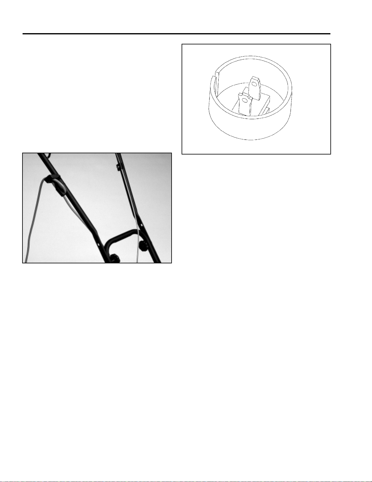
1. Form a loop in extension cord and secure it in cord
lock (Figure 5).
Fi
ure 5
2. Connect extension cord to mower (Figure 5).
Scan7-a
0663-002
To reduce the risk of electric shock, this mower has a
polarized plu
other) (Fi
polarized outlet only one way. If the plu
fully in the receptacle, reverse the plu
not fit, consult a qualified electrician to install the
proper plu
way.
Carefree Mower Service Manual 3 - 1
receptacle (one blade is wider than the
ure 4). An extension cord plug will fit in a
does not fit
. If it still does
. Do not change the plug receptacle in any
Note: Do not unplug extension cord by pulling on
cord. To unplug, grasp the plug, not the cord.
Page 23

OPERATIONAL TIPS (120 VOLT MODELS)
WARNING
POTENTIAL HAZARD
• The electrical cord could be damaged.
WHAT CAN HAPPEN
• A damaged electrical cord could cause a shock
or fire.
HOW TO AVOID THE HAZARD
• Thoroughly inspect electrical cord before
charging unit. If cord is damaged, do not charge
unit. Replace or repair damaged cord
immediately . Contact your TORO service dealer
for assistance.
Plan Your Mowing Pattern
By following the suggested mowing pattern, the risk of
running over the cord with the mower will be reduced,
and the cord will not sustain unnecessary wear. Do not
allow extension cord to wrap around trees, shrubs or
other obstacles.
1. Begin mowing near the electrical outlet and work
outward (Figure 6). Mow back and forth.
Maintenance
WARNING
POTENTIAL HAZARD
• When extension cord is connected to mower
and plugged into a normal household outlet, the
mower is operational. Someone could
accidentally start the mower.
WHAT CAN HAPPEN
• Accidental startin
injure you or other bystanders.
•
HOW TO AVOID THE HAZARD
• Always remove extension cord from mower
receptacle when leaving mower unattended,
even for a short period of time.
Cleaning
Before cleaning mower, stop motor, wait for all moving
parts to stop, and disconnect extension cord from
mower.
IMPORTANT: Do not clean mower with a garden
hose. Moisture can be trapped in mower and
may cause corrosion of internal parts.
g of mower could seriously
Figure 6
2. When turning at the end of a cut path, be very
careful not to mow across the extension cord.
WARNING: If extension cord is damaged, do
not operate unit. Replace or repair damaged
cord immediately . Contact your T ORO service
dealer for assistance.
3 - 2 Carefree Mower Service Manual
5306-118
Page 24

OPERATIONAL TIPS (120 VOLT MODELS)
g
g
g
After Every Use
• Clean the underside of the mower housing. Be
particularly careful to keep the front cavity clear of
all debris (Figure 7). Remove dirt and grass
clippings with a hardwood scraper. Avoid burrs
and sharp edges.
ure 7
Fi
• Brush all debris off top of mower housing.
Scan-4
• Check for any discolored or charred wires or switch
contacts. If any are damaged, see your Authorized
Toro Service Dealer for repairs.
Blade
Always mow with a sharp blade. A sharp blade cuts
cleanly and without tearing or shredding the grass
blades like a dull blade.
WARNING
POTENTIAL HAZARD
• Motor could be started by someone accidentally.
WHAT CAN HAPPEN
• Accidental starting of motor could cause serious
injury to operator or bystanders.
HOW TO AVOID THE HAZARD
• Do not attempt to inspect, remove or replace
blade without first disconnecting extension cord
from the mower.
Once A Year
• Remove top shroud (Figure 8) and clean out any
debris underneath it with compressed air, a
vacuum cleaner, or a brush.
IMPORTANT: Do not use metal objects to clean
around battery. If metal objects contact the
positive and ne
this could short the battery. The battery or
conductor may overheat and cause burns.
gative posts at the same time,
1. Stop motor and wait for all moving parts to stop.
Disconnect extension cord from mower.
2. Tip mower on its side (Figure 9).
Fi
ure 9
0663-008
Fi
ure 8
Carefree Mower Service Manual 3 - 3
0663-006
Page 25

OPERATIONAL TIPS (120 VOLT MODELS)
g
3. EXAMINING BLADE - Carefully examine blade for
sharpness and wear, especially where flat and
curved parts meet. Since sand and abrasive
material can wear away the metal that connects
the flat and curved parts of the blade, check blade
before using the mower. If a slot or wear is
noticed replace blade (Fi
Note:
For best performance, install new blade
before cutting season begins. During the year, file
down small nicks to maintain the cutting edge.
ure 10). Refer to step 4.
4. REMOVING BLADE - Grasp end of blade using a
rag or thickly padded glove. Remove blade bolt,
washer and blade (Figure 11).
Figure 11
5. SHARPENING BLADE - Using a file, sharpen top
side of blade and maintain original cutting angle
(Figure 12). The blade will remain balanced if
same amount of material is removed from both
cutting edges.
Scan-4
Figure 10
Scan-10-b
WARNING
POTENTIAL HAZARD
• A worn or damaged blade could break and a
piece of blade could be thrown in operator's or
bystander's direction.
WHAT CAN HAPPEN
• A thrown piece of blade could cause serious
personal injury or death to operator or
bystanders.
HOW TO AVOID THE HAZARD
• Inspect blade periodically for wear or dama
• Replace a worn or damaged blade.
ge.
IMPORTANT: Check balance of blade by
putting it on a blade balancer. An inexpensive
balancer can be purchased at a hardware
store. A balanced blade stays in a horizontal
position and an unbalanced blade settles to
the heavy side. If blade is not balanced, file
more metal off cutting edge on heavy end of
blade.
SHARPEN AT THIS
ANGLE ONLY
Figure 12
Scan-2
3 - 4 Carefree Mower Service Manual
Page 26

OPERATIONAL TIPS (120 VOLT MODELS)
g
g
g
g
g
g
6. Reinstall sharp, balanced blade, washer and
blade bolt. Sail part of blade must point toward
top of mower housing to ensure correct
installation. Washer is curved and must be
reinstalled with curve side down as shown in
(Figure 13). Tighten blade bolt to 35-40 ft. lbs.
(48-54 N·m).
Fi
ure 13
Servicing Double-Insulated Mower
Scan-3
Storage
Store mower in a cool, clean, dry place. Cover mower
to keep it clean and protected.
1. Clean mower housing. See “Cleanin
page 3 - 2.
2. Remove grass clippings, dirt and grime from
external parts of the shrouding and top of mower
housing.
3. Check condition of blade. See “Blade” section on
page 3 - 3.
4. Tighten all nuts, bolts, and screws.
” section on
In a double-insulated mower, two systems of insulation
are provided instead of
means is provided on a double-insulated mower, nor
should a means for
Servicin
care and knowled
only by qualified service personnel. Replacement
parts for a double-insulated mower must be identical to
the parts they replace. A double-insulated mower
is marked with the words "DOUBLE INSULATION" or
"DOUBLE-INSULATED." The symbol (square within a
square) may also be marked on the mower.
a double-insulated mower requires extreme
rounding. No grounding
rounding be added to the mower.
e of the system, and should be done
Carefree Mower Service Manual 3 - 5
Page 27

)
g
g
g
g
g
g
g
g
g
g
g
g
g
g
g
g
3
OPERATIONAL TIPS (24/36 VOLT MODELS
Charging (battery powered models)
Standard with all battery powered models is an
automatic char
the char
needed. When the batteries are fully char
er turns off. This charger also has the ability to
char
sense when the batteries are too hot or too cold to be
char
ed. In that situation, charging is suspended until
the temperature returns to a normal ran
er. This charger will periodically check
e status of the batteries and charge them as
ed, the
e.
WARNING
POTENTIAL HAZARD
• Contact with water while operating unit could
cause electric shock.
WHAT CAN HAPPEN
• Electric shock can cause injury or death.
HOW TO AVOID THE HAZARD
• Don't handle plu
while standing in water.
• Use only a UL listed (CSA certified in Canada)
extension cord.
It takes approximately 12-16 hours to char
dischar
use. If the battery is not rechar
the battery life will be shortened. Rechar
mower is only run for a few minutes. This battery
does not have a "memory."
ed battery. Char
g or mower with wet hands or
e a fully
e the battery after every
ed after every use,
e even if
2. If key is in plu
3. (North American Models)
Insert extension cord into the plug receptacle and
connect other end of extension cord to a normal
120 volt household outlet (Figure 15). See
“Secure Extension Cord” on pa
(European Models Only)
Lift the rain shield, insert the extension cord into
the plug receptacle, then connect other end of
extension cord to a normal 230 volt household
outlet (Figure 15). Use only a CE listed extension
cord (included with mower).
g receptacle, remove it (Figure 14).
Figure 14
e 3 - 1.
Scan-5-a
Note: The battery is charged at the factory. However,
before usin
rechar
operatin
Note: Battery Charger Power Draw
To char
1. Always charge mower in a dry area protected from
the weather. Also, keep mower away from water
and any flammable substances.
Carefree Mower Service Manual 3 - 7
mower the first time, it is necessary to
e battery and ensure it has a full charge before
.
When Charging - 50 watts
Not Charging - 4 - 5 watts
e battery:
Figure 15
1463-003-a
Page 28

OPERATIONAL TIPS (24/36 VOLT MODELS)
g
g
4. The three vertical LED lights on the control panel
will indicate the charging status (Figure 16). Refer
to the Charging Chart below (Fi
summary of the LED lights.
The red light on the control panel will begin to
flash to indicate battery is present and is ready to
charge.
Figure 16
ure 17) for a
Scan-1-a
5. After a few minutes, the red light will stop flashing
and become a steady red. This indicates the
battery is charging.
6. When the battery is almost fully charged, the red
light will go out and the green light will go on. The
red and green light will alternately turn on and off.
When the green light is on more than the red light,
the battery is fully charged.
IMPORTANT: Your mower has been designed
to be safe if left continually on charge for
extended periods of time. It is recommended
that the battery be left continually on charge
when it is not in use.
season, the mower can be unplugged and stored
if the battery is fully charged.
Note:
When the mower is left on charge, it is
normal for the red and green lights to alternately
turn on and off.
During the non-mowing
LED CHARGING LIGHTS CHART
Charging Status Red Green Yellow
Pre-charge qualification — charger testing battery
condition/trickle charging battery. Trickle charge can last
from minutes to hours.
Battery charging on off off
Battery charged off on off
Battery absent or defective off off on
Charging fault - charger malfunctioning not applicable not applicable not applicable
Charge pending — temperature too hot or too cold to
charge
Figure 17
blinking off off
not applicable not applicable blinkin
3 - 8 Carefree Mower Service Manual
Page 29

OPERATIONAL TIPS (24/36 VOLT MODELS
)
g
g
g
g
g
g
g
g
ging
gg
g
ging
g
g
g
g
g
ging
g
g
Storage (battery models)
The best storage for a battery is a cool dry place. In
fact, a fully char
of about -50° F without freezin
factor for batteries, this is thermometer temperature.)
However, a dischar
freezin
New mowers are char
char
be char
in the carton to allow easy plu
cord. We would recommend char
hours.
Consumers should leave the machine plu
not in use. The automatic char
failure from over or under char
cause of battery failure. Make sure that the outlet used
is not switched (turned off with the li
amount of electricity used would be difficult to identify
on the electric bill as it will
Durin
the battery; if it is too cold or the battery is fully
char
the batteries, the current draw will not be lar
point of water.
e is good for about six months. Inventory must
ed at six month intervals. An access panel is
the Winter, the charger will come on and test
ed, the charger shuts off. Even when charging
ed battery will withstand temperatures
. (Windchill is not a
ed battery will freeze at +32° F, the
ed before shipping. This
in with an extension
overnight 12-14
ed in when
er will prevent battery
, the most common
ht switch). The
enerally be very small.
e.
Battery Power Status
The three horizontal LED lights at the top of the control
panel indicate approximately how much charge is left in
the battery while the mower is in operation (Figure 18).
The lights are only accurate when the mower is
operating and cutting grass. The following is an
explanation of the symbols under the battery power
status LED li
• Full Box — Battery is between 50% - 100%
charged.
• Half Full Box — Battery is between 5% - 50%
charged.
• Empty Box — Battery has less than 5% charge left
and should be recharged.
IMPORTANT: The battery's life will be
shortened if mower is run after battery lights
have turned off. Do not continue to mow.
Recharge battery.
ghts:
Battery Life — If the char
followed, batteries will
4-5 years. However, if stored in a dischar
condition, the batteries can fail in a few months.
recommendations are
enerally need replacing every
ed
Figure 18
Operation
This mower is intended for residential use only.
Scan-1-b
Carefree Mower Service Manual 3 - 9
Page 30

OPERATIONAL TIPS (24/36 VOLT MODELS)
Key
The mower will only operate when key is fully seated in
plug receptacle (Figure 19). To prevent accidental
starting or unauthorized use of mower, always remove
key from plug receptacle when leaving mower
unattended. The key has a tab with a hole in it to allow
key to be hung from a nail, out of the reach of children.
Read warning label on key.
Figure 19
Scan-5-a
3. Pull control bar toward handle while pushing down
slide on control (Figure 21).
Figure 21
4. Squeeze control bar to handle (Figure 22).
Note:
Keep mower running when turning mower.
Turning mower off when making a turn does not
save battery energy.
Scan-11-a
Starting/Stopping Instructions
To Start Motor
1. Push mower onto a flat concrete or asphalt
surface.
Note:
Starting mower in thick grass could cause
mower to clog.
2. Insert key fully into plug receptacle (Figure 20).
Figure 22
(A) Control Bar and Handle
Fig 15
Figure 20
3 - 10 Carefree Mower Service Manual
Scan-6-a
Page 31

OPERATIONAL TIPS (24/36 VOLT MODELS
)
g
g
To Stop Motor
1. Release control bar.
2. Remove key from plug receptacle if mower will be
unattended for any period of time. Hang key in a
high place out of reach of children.
3. Always char
use of mower. If battery is not charged after
each use, battery life will be shortened. See
“Char
ging (battery powered models)” on page 3 -
7.
IMPORTANT: Your mower has been designed
to be safe if left continually on charge for
extended periods of time. It is recommended
that the battery be left continually on charge
when it is not in use during the mowing
season. During the non-mowing season, the
mower can be unplugged and stored if the
battery is fully charged.
ge battery immediately after each
Circuit Breaker
If mower is run under too much load, the circuit breaker
will trip. Follow these instructions to reset circuit
breaker.
2. Wait 30 seconds to 1 minute before pushing in
circuit breaker button (Fi
Figure 24
(A) Reset Button
3. Reinstall key in plug receptacle.
4. Resume cutting under less load.
If circuit breaker repeatedly trips, raise the height-of-cut
or side discharge.
ure 24).
Scan-6-b
IMPORTANT: Never reset circuit breaker when key
is in receptacle and control bar is squeezed to
handle.
1. Remove key from plu
g receptacle (Figure 23).
Fi
ure 23
Scan-5-a
Mowing Tips
Battery Run Time
With a battery powered lawn mower, the condition of
the grass and the way that you mow the grass will
affect how long the battery will run on a single
charge at each mowing.
The following are some things that will affect battery
run time:
• Moisture content of grass — The more moisture
there is in the grass, the faster the battery will run
down.
• Walking/mowing speed — The faster you walk, the
faster the battery will run down.
• Mode of operation — Mulching grass requires the
most battery energy. Bagging requires the second
highest amount of battery energy, and side
discharging uses the least.
Carefree Mower Service Manual 3 - 11
Page 32

OPERATIONAL TIPS (24/36 VOLT MODELS)
• Height-of-cut setting - If you are experiencing
problems with the battery running down too fast, try
raising the height-of-cut setting one notch.
General Mulching Tips
Your mower is designed to mulch grass when the
mulch door is completely closed (Figure 25).
Figure 25
Scan-9-a
• Grass grows at different rates at different times of
the year. In the heat of summer, it is generally best
to cut grass at the 2-1/2", 3" or 3-1/2" height-of-cut
settings. Only about 1/3 of the grass blade should
be cut off. Cutting below the 2-1/2"setting is not
recommended unless grass is sparse or it is late
fall when grass growth begins to slow down.
• When changing height-of-cut from the established
setting (ex. 2-1/2", 3", or 3-1/2") to a lower height,
the grass may appear ragged or uneven until the
grass adjusts to the new established height-of-cut
and regains its normal appearance.
• When cutting grass over six inches tall, you may
want to first mow using the side discharge chute or
try the highest height-of-cut setting and a slower
walking speed; then mow again at a lower setting
for best lawn appearance. If grass is too long and
leaves clumps on top of lawn, mower may plug and
cause motor to stall.
• Alternate mowing direction. This helps disperse
clippings over lawn for even fertilization.
Follow these instructions whether cutting grass or
leaves for the best cutting results and lawn
appearance:
• Maintain a
season. Periodically file down nicks on blade.
Only mow dry grass or leaves.
•
leaves tend to clump on yard and may cause
mower to plug or motor to stall. They may also be
slippery to walk on and could cause you to slip and
fall.
sharp blade
throughout the cutting
Wet grass and
WARNING
POTENTIAL HAZARD
• Wet grass or leaves can cause you to slip and
contact blade.
WHAT CAN HAPPEN
• Blade contact can seriously injure you.
HOW TO AVOID THE HAZARD
• Mow only in dry conditions.
• Clean clippings or leaves from underside of mower
deck after each mowing.
If the finished cut lawn appearance is unsatisfactory,
try one or more of the following:
• Sharpen the blade.
• Walk at a slower pace while mowing.
• Raise the height-of-cut setting on your mower.
• Cut grass more frequently.
• Overlap cutting swaths instead of cutting a full
swath with each pass.
• Set height-of-cut on front wheels one notch lower
than rear wheels. (Example: set front wheels at 2
inch setting and rear wheels at 2.5 inch setting.)
Cutting Leaves
• When cutting is complete, always be sure that 50%
of the lawn shows through the cut leaf cover. This
may require one or more passes over the leaves.
• For light leaf coverage, position all wheels at the
same height-of-cut setting.
3 - 12 Carefree Mower Service Manual
Page 33

OPERATIONAL TIPS (24/36 VOLT MODELS
)
g
• Walk at a slower mowing speed if leaves are not
being cut up finely enough to be hidden down in
the grass.
• If you cut up a lot of oak leaves, you might want to
add lime to your grass in the spring. Lime reduces
the acidity of oak leaves.
Adjusting Height-of-Cut
The mower has five height-of-cut adjustments: 1-1/2",
2", 2-1/2", 3", and 3-1/2". The rear adjustment lever
adjusts the hei
the front adjustment lever adjusts both front wheels.
ht-of-cut for both rear wheels, and
WARNING
POTENTIAL HAZARD
• Adjusting height-of-cut levers could bring hands
into contact with moving blade.
WHAT CAN HAPPEN
• Contact with blade could cause serious personal
injury.
2. For easier adjustment, lift housing up so wheels
are off the ground. Do not place hands under
deck to lift housin
toward wheel and move lever to desired settin
(Figure 26). Ensure pin on adjustment lever
engages notch in mower housing. Adjust all
wheels to the same setting.
Note: For easier adjustment of rear wheels, grasp
lower handle with one hand and lift up mower
slightly so wheel is off the ground. Then squeeze
adjustment handle toward wheel.
g. Squeeze adjustment lever
g
HOW TO AVOID THE HAZARD
• Stop motor, disconnect extension cord from
mower and wait for all moving parts to stop
before changing the height-of-cut.
• Do not put fingers under housing to lift mower
when adjusting height-of-cut levers.
1. Stop motor and wait for all moving parts to stop.
Disconnect extension cord from mower.
Figure 26
Maintenance
WARNING
POTENTIAL HAZARD
• When extension cord is connected to mower
and plugged into a normal household outlet, the
mower is operational. Someone could
accidentally start the mower.
WHAT CAN HAPPEN
• Accidental startin
injure you or other bystanders.
HOW TO AVOID THE HAZARD
• Always remove extension cord from mower
receptacle when leaving mower unattended,
even for a short period of time.
g of mower could seriously
Scan8-a
Carefree Mower Service Manual 3 - 13
Page 34

OPERATIONAL TIPS (24/36 VOLT MODELS)
g
Cleaning
Before cleaning mower, stop motor, wait for all moving
parts to stop, and disconnect extension cord from
mower.
IMPORTANT: Do not clean mower with a garden
hose. Moisture can be trapped in mower and
may cause corrosion of internal parts.
After Every Use
• Clean the underside of the mower housing. Be
particularly careful to keep the front cavity clear of
all debris (Fi
clippings with a hardwood scraper. Avoid burrs
and sharp edges.
ure 27). Remove dirt and grass
Once A Year
• Remove top shroud (Figure 28) and clean out any
debris underneath it with compressed air, a
vacuum cleaner, or a brush.
IMPORTANT: Do not use metal objects to clean
around battery. If metal objects contact the
positive and negative posts at the same time,
this could short the battery. The battery or
conductor may overheat and cause burns.
Figure 27
• Brush all debris off top of mower housing.
Scan-4
Figure 28
• Check for any discolored or charred wires or switch
contacts. If any are damaged, see your Authorized
Toro Service Dealer for repairs.
Scan-9
Blade
Always mow with a sharp blade. A sharp blade cuts
cleanly and without tearing or shredding the grass
blades like a dull blade.
WARNING
POTENTIAL HAZARD
• Motor could be started by someone accidentally.
WHAT CAN HAPPEN
• Accidental startin
injury to operator or bystanders.
HOW TO AVOID THE HAZARD
• Do not attempt to inspect, remove or replace
blade without first disconnecting extension cord
from the mower.
g of motor could cause serious
3 - 14 Carefree Mower Service Manual
Page 35

OPERATIONAL TIPS (24/36 VOLT MODELS
)
g
g
g
g
1. Stop motor and wait for all moving parts to stop.
Disconnect extension cord from mower.
2. Tip mower on its side (Fi
Fi
3. EXAMINING BLADE — Carefully examine blade
for sharpness and wear, especially where flat and
curved parts meet. Since sand and abrasive
material can wear away the metal that connects
the flat and curved parts of the blade, check blade
before usin
noticed, replace blade (Figure 30). Refer to step 4.
g the mower. If a slot or wear is
ure 29).
ure 29
Scan-4
WARNING
POTENTIAL HAZARD
• A worn or damaged blade could break and a
piece of blade could be thrown in operator's or
bystander's direction.
WHAT CAN HAPPEN
• A thrown piece of blade could cause serious
personal injury or death to operator or
bystanders.
HOW TO AVOID THE HAZARD
• Inspect blade periodically for wear or damage.
• Replace a worn or damaged blade.
4. REMOVING BLADE — Grasp end of blade using
a rag or thickly padded glove. Remove blade bolt,
washer, and blade (Fi
ure 31).
Note: For best performance, install new blade
before cuttin
down small nicks to maintain the cutting edge.
g season begins. During the year, file
Fi
ure 30
Scan-10-b
Figure 31
0663-008
Carefree Mower Service Manual 3 - 15
Page 36

OPERATIONAL TIPS (24/36 VOLT MODELS)
5. SHARPENING BLADE — Using a file, sharpen
top side of blade and maintain original cutting
angle (Figure 32). The blade will remain balanced
if same amount of material is removed from both
cutting edges.
IMPORTANT: Check balance of blade by
putting it on a blade balancer . An inexpensive
balancer can be purchased at a hardware
store. A balanced blade stays in a horizontal
position and an unbalanced blade settles to
the heavy side. If blade is not balanced, file
more metal off cutting edge on heavy end of
blade.
SHARPEN AT THIS
ANGLE ONLY
SHARPEN AT THIS
ANGLE ONLY
6. Reinstall sharp, balanced blade, washer, and
blade bolt. Sail part of blade must point toward
top of mower housing to ensure correct
installation. Washer is curved and must be
reinstalled with curve side down as shown in
(Figure 33). Tighten blade bolt to 35-40 ft. lbs.
(48-54 N·m).
Figure 33
Scan-3
Figure 32
Scan-2
3 - 16 Carefree Mower Service Manual
Page 37

g
g
4
TESTING ELECTRICAL COMPONENTS
120 Volt Models
There are four components in the electrical system:
A. Motor.
B. 2 wires between the motor and switch.
C. Switch.
D. Wires between the switch and the plug
receptacle.
Safety Information
Electric products have a different set of safety
uidelines:
• Use common sense. High voltage and high current
potentials are present.
• Remove all jewelry (i.e. rings, watches) before
performing service work to prevent accidental short
could
circuits. An accidental short
burns. This is especially important on battery
powered units.
• Do not touch live wires as the resulting shock could
be unpleasant or even fatal.
cause severe
120 Electrical System Testing
Because of the simplicity of the system, there are only
two tests that need to be made.
Description Specification
Motor Input Voltage 108 - 132 VAC
Motor Resistance* 0.8 to 1.2 ohms
*Measure at motor leads with power disconnected.
A. Motor test (Figure 35).
Wiring Diagrams
Always consult the wiring diagram under the cover for
proper wire connections, location, and polarity (Figure
34).
Fi
ure 34
5306-119
Figure 35
B. Wires between the motor and switch — check for
breaks, damaged insulation or loose terminals.
C. Switch — the switch is a standard on-off switch
and can be checked with a continuity light or
ohmmeter.
NOTE: As this switch is activated by a cable, verify
that the cable adjustment correctly activates the
switch.
D. Wires between the switch and plug receptacle —
these wires should be checked in the same way as
the motor to switch wires. There is one additional
possibility. The use of an extension cord with a
poor terminal may result in burnt terminals on the
mower. A loose connection between the cord and
mower can cause arcin
Should this occur, replace the terminals on the
mower and either the extension cord or the plug on
the end of the cord.
g and burnt terminals.
5306-120
Carefree Mower Service Manual 4 - 1
Page 38

TESTING ELECTRICAL COMPONENTS
g
g
Battery Powered Models
The electrical components in a battery powered model
are as follows:
A. Motor.
B. Solenoid.
C. Batteries.
D. Char
E. Transformer.
F. Switch.
G. Wire harness.
H. Safety key terminals.
I. Circuit breaker.
er — includes indicator lights.
Motor Testing
There is one simple test that can be made on the
motor. Unplug the motor from the wire harness. Set
an ohmmeter on Rx1 and zero the meter. Attach one
test probe to each of the wires going to the motor and
note the reading. SLOWLY rotate the armature of the
motor and watch the tester. The needle should move a
little, but at no time should it go to the extreme ends of
the scale. There should be some resistance there at all
times. If the needle reads zero, there is a short circuit
in the motor and it should be replaced. If the needle
goes to infinity (looks like an 8 on its side) a wire inside
is broken or the brushes are not contacting the
armature. If you find a broken wire accessible and can
splice it, do so. If the broken area cannot be found or is
in an area where it cannot be spliced, the motor must
be replaced.
SPECIAL NOTE:
will not only distort your readin
damage your tester. Remember when a permanent
magnet motor has its armature turned manually, it
becomes a generator.
If you rotate the armature too fast, it
gs, but could possibly
Figure 36
Terminals Description
A - A Normally closed terminals
B - B Normally open terminals
C - C Connections to coil
Disconnect the wire harness from the solenoid
terminals prior to performing this resistance test.
Connect an ohmmeter set on the RX1 scale to the coil
terminals as shown below. The coil resistance should
read between 46 and 55 ohms (Fi
ure 37).
36294102
Solenoid Testing
A solenoid is used to protect the switch from arcing
when it’s turned on and off (Figure 36).
Figure 37
Measurement Specification
Solenoid coil resistance 46 - 55 ohms
4 - 2 Carefree Mower Service Manual
3629104
Page 39

TESTING ELECTRICAL COMPONENTS
gag
g
g
g
g
g
This 24 volt solenoid requires a minimum of 18 volts to
en
e, therefore, it is necessary to use the actual
mower batteries to test it (Fi
terminals by connectin
ure 38). Test the A - A
power and the ohmmeter as
shown below.
ure 38
Fi
36294105
A properly functioning solenoid will yield the following
results:
Power Result at Terminals A - A
Not connected Continuity (R = 0 ohms)
Connected to C - C No Continuity (R = infinity)
The following results indicate a solenoid that is
functioning properly:
Power Result at Terminals B - B
Not connected No Continuity (R = infinity)
Connected to C - C Continuity (R = 0 ohms)
Testing Batteries
Before reading voltage, the batteries must rest a
minimum of one hour after charging to prevent an
incorrect reading. Test the batteries using a digital
voltmeter.
Note: Voltage will increase from original reading about
.25 volts per hour for up to 4 hours. Also, charge
output voltages will vary with temperature: higher in
cold and lower in heat.
Combined
Voltage Test
Combined voltage
(charger off)
Combined Voltage
(charger on at
room temp.)
24 Volt 36 Volt
24 - 26 VDC 36 - 39 VDC
26.5 - 30.5 VDC 39.5 - 45.5 VDC
Perform the same test as above on the B - B terminals
(Fi
ure 39).
Fi
ure 39
36294103
Individual
Voltage Test
Individual Voltage 12 - 13 VDC 6 - 6.5 VDC
Toro
20647 &
20649 Only
All
Others
Carefree Mower Service Manual 4 - 3
Page 40

TESTING ELECTRICAL COMPONENTS
Charger Testing
This charger’s control system cannot be tested using
common testing equipment. However, if the charging
lights work, the charger is likely working.
There is one test that can indicate if the charger has
output. Attach a DC voltmeter to the battery terminals
(positive on one end of the pack and ne
other). You should read about 24 or 36 volts,
depending on the model. Plug the charger into the
mower and wait for it to go through its testing cycle.
when the red light glows steadily, note the reading on
the voltmeter. If you cannot see a voltage increase,
wait a few minutes and check the reading again. When
the charger starts charging, it may take as much as 30
minutes to get up to full voltage. If it reads the same as
before, the charger has no output. Before replacing
the charger, check the transformer and wires that
supply power to the charger. If there is power going
into the charger but not coming out, the charger is bad.
Remember if the batteries are fully charged, the
charger will read that and turn off. If you suspect that is
the problem, run the mower for a time to drain the
batteries somewhat.
gative on the
Flashing Yellow Charging Indicator
A flashing yellow indicator shows that the temperature
is either too hot or too cold. When the temperature
situation is corrected, the red indicator will illuminate
and the charger will resume charging at the rate last
determined (Figure 41).
Note:
If left in the garage over the Winter, the charger
may flash yellow for months, only to begin charging on
the first warm Spring day. This situation is perfectly
normal. The unit should be left plugged in while the
yellow light flashes.
Charging Indicator Lights
There are two sets of indicator lights (actually light
emitting diodes or LEDs). One set is the charging
indicators and the other indicates the charge
remaining. In the next few paragraphs, we’ll be
covering the information communicated by each of the
lights (Figure 40).
Figure 40
0674-013
Figure 41
5306-111
4 - 4 Carefree Mower Service Manual
Page 41

TESTING ELECTRICAL COMPONENTS
g
g
g
g
gg
g
g
g
Flashing Red Charging Indicator
A flashing red light indicates that the charger is
performin
sta
batteries to determine if they will be able to take a
char
temperature to insure that its not too hot or too cold to
char
Note: The Pre-Char
about 4 minutes and occurs each time the cord is
plu
the char
before
the “
Pre-Charge Qualification.
e, the charger sends a trickle charge to the
e. The charger also evaluates the ambient
e (Figure 42).
ge Qualification generally takes
ed in. If the batteries are extremely discharged,
er may continue attempting to charge them
iving up and lighting the yellow failure indicator.
” During this
Steady Red Charging Indicator
After completion of the “Pre-Charge Qualification, the
red charging indicator will glow steady red if no
problems were discovered. This indicates that the
charger is charging. If the batteries were fully charged,
the charger will charge at an extremely low rate for
about 30 minutes before lighting the green light. When
the batteries are in need of charging, the red light
indicates charging at the “full charge” rate (Figure 43).
Fi
ure 42
5306-108
Figure 43
5306-109
Steady Yellow Charging Indicator
If an open circuit, fault, or VERY low battery voltage
was discovered, the charger will turn itself off and turn
on a steady yellow charging indicator. This indicates a
problem (Figure 44).
The Operator’s Manual recommends bringing the unit
to a Toro Authorized Service Dealer whenever a steady
yellow light is on.
Figure 44
Carefree Mower Service Manual 4 - 5
5306-110
Page 42

TESTING ELECTRICAL COMPONENTS
Steady Green Charging Indicator
A steady green charging indicator shows that the
batteries are fully charged. Even once the fully
charged level is achieved, the charger still periodically
re-evaluates battery condition to determine if they need
to be “topped off.” If so, the charger will switch to the
charge mode (indicated by the steady red indicator).
Once the batteries are topped off, the charger
discontinues charging and illuminates the green light
(Figure 45).
Charge Remaining Indicator Lights
The battery power status indicator lights show how
much charge remains (Figure 46).
Charge Remaining Lights
Figure 46
They indicate the following:
Lights Charge Remaining
0674-006
Figure 45
5306-112
Three Lights 50 - 100%
Two Lights 25 - 50:
One Light 5 - 25%
4 - 6 Carefree Mower Service Manual
Page 43

TESTING ELECTRICAL COMPONENTS
g
Transformer Testing
Test the transformer using a volt/ohmmeter (Figure 47).
#3
#1
#2 & #4
Fi
ure 47
US & Canadian Models
# Test 24 Volt Models 36 Volt Models
1 Transformer Input Voltage 108 to 132 VAC 108 to 132 VAC 207 - 244 VAC @ 50 hz
2 Transformer Output Voltage* 37.8 to 42.1
3 Transformer Primary Resistance 4.5 to 5.3 Ohms 4.6 to 5.4 Ohms 23 - 29 Ohms
VAC*
0674-008
52.0 to 57.8
VAC*
European, U.K., &
Swiss Models
43.2 VAC*
4 Transformer Secondary Resistance
(wires removed)
* Open circuit voltage measured with wires removed and input voltage
at 120 volts A.C.
NOTE: As the input line voltage varies from normal (120 VAC or 230 VAC) the output will vary accordingly.
0.6 to 1.0 Ohms 1.2 to 1.6 Ohms 1 - 1.4 Ohms
*Open circuit voltage measured with
wires removed and with the input
voltage at 230 VAC.
Carefree Mower Service Manual 4 - 7
Page 44

TESTING ELECTRICAL COMPONENTS
Switch Testing
Switch Testing (battery powered models)
The switch used is a two position, three terminal
switch. Two tests must be made to assure the switch
works properly. An ohmmeter or continuity light will
properly test this switch. Continuity must be present as
shown in the diagram (Figure 48).
Figure 48
plug
Testing Safety Key Terminals
Test by checking for 24 or 36 volts between both
terminals with the key removed and the control bar in
the ON position (Figure 49).
remaining indicator will light. (It is not necessary to
remove any connectors for this test.) Assure the circuit
breaker is closed for this test.
NOTE:
connection could result in burnt terminals.
Important
probes into them.
The safety key handles hi
— Do not distort connectors by forcing test
NOTE:
The charge
gh current. A poor
Position 1 Position 2
B + C continuity B + A continuity
Wire Harness
The wire harness on battery powered models does not
contain any special components, such as diodes.
Wires can be tested for continuity in a normal manner.
Possible failure modes include broken wires, loose
terminals, or damaged insulation.
Wiring diagrams are located on the underside of the
hood (motor cover) and in the parts catalog. Be sure to
use the diagram for your specific model.
Figure 49
0674-011
Circuit Breaker Testing
Test the circuit breaker (Figure 50) with an ohmmeter
for continuity. It should be continuous.
NOTE:
The circuit breaker is a push to reset type.
Figure 50
4 - 8 Carefree Mower Service Manual
5306-115
Page 45

g
g
g
g
g
5
BLADE STOPPING SYSTEMS
Blade Stopping Systems
There are two blade stopping systems in use on the
various battery and electric powered mowers — one for
the 120 vac models and the other for the battery
powered models. Both systems are desi
the blade within three seconds of the operator
releasin
the bail on the handle.
ned to stop
120 Volt Blade Stopping System
The 120 vac mowers use a spring loaded brake
applied to a brake drum. When the control bail on the
handle is squeezed, this brake is retracted by a means
of a cable (Fi
ure 51).
Battery Mower Systems
The battery powered models use a permanent magnet
motor. If you turn the armature of a permanent magnet
motor by hand, the motor becomes a generator. We
use that electricity to stop the motor. With the motor
running normally, the operator releases the handle.
The switch disconnects the battery from the motor then
connects the two wires from the motor to
(shorting them together). By doing this, the electricity
the motor then generates is directed back into the
motor in the opposite direction. This results in slowing
the motor. Also, as the motor slows down, it generates
less electricity. Soon the two forces balance each
other out and the motor stops. This system is very
effective and does not require brake parts to achieve
the required stopping time. See “Switch Testin
page 4 - 8 for the internal workings of the switch.
gether
” on
Fi
ure 51
0663-014
Carefree Mower Service Manual 5 - 1
Page 46

g
g
g
g
g
g
g
g
g
g
g
g
g
g
g
g
g
g
g
6
DISASSEMBLY & REASSEMBLY
Disassembly — Battery Models
All the electrical components are located under the
hood. The on/off switch is controlled by a cable that
runs alon
there is access to the test points of all electrical
components.
To access the motor, wirin
char
four screws retainin
To remove the motor, on battery powered models,
remove the hood and disconnect the battery terminals
and remove the solenoid. Turn the mower over and
remove the blade, bushin
screws holdin
NOTE: On battery models, the solenoid must be
removed first as it uses one of the motor mountin
screws.
side the handle. With the hood removed,
, switch, and batteries,
er and solenoid (on battery models), remove the
the hood and lift the hood off.
fan, washer, and the four
the motor in place.
Transformer Replacement — Battery
Models
Battery Replacement
The batteries are held in place by a strap. To remove
the strap, remove either of the screws securing the
ends of the strap. However, the batteries are resting
on double sided tape. It will be necessary to slide a
putty knife or similar object under the batteries to break
the tape loose. The battery pack can then be removed.
Note the way the battery terminals are positioned so
the new batteries can be installed property.
Blade Replacement — 120 Volt Models
The blade is attached to a spindle shaft. Tip the mower
on its side. Remove the blade retaining nut and
washer.
NOTE: You may find it helpful to remove the motor
cover and hold the lar
loosen the blade nut.
ge drive pulley to tighten or
Remove the hood and disconnect the battery cables.
Lift the char
er are four wires which plug into the charger
char
terminals throu
wires, note that the wires are in pairs; ta
necessary to remember which wires
Remove the nut holdin
to the motor mountin
side and remove the blade, bushin
Remove the four screws holdin
chassis. Be ready to catch the motor and set it aside.
Remove the 1 1 screws holdin
Lift the liner off. The transformer is between the rear
wheels inside a plastic housin
the transformer when it is removed. Replace the
transformer in the housin
the chassis. Make sure the transformer terminals are
in the correct slots. Reinstall the liner, blade, fan, etc.
See the specifications for the proper torque on all
hardware.
er assembly from its slot. Below the
h slots in the body. Unplug these four
them if
o where.
the solenoid mounting bracket
screw. Turn the mower on its
, fan, and spacer.
the motor to the
the liner to the chassis.
. Note the orientation of
and replace the housing in
Carefree Mower Service Manual 6 - 1
Page 47

DISASSEMBLY & REASSEMBLY
g
Blade Brake — 120 Volt Models
1. Remove the motor cover retained with four
screws.
2. Roll the belt off the large pulley. See ”Belt
Replacement" on page 6 - 3.
3. Remove the nut on the large pulley and remove
the pulley (Figure 52).
NOTE:
down when the pulley is removed.
(A) Nut (B) Belt (C) Pulley
4. Lift the brake drum off the spindle shaft.
The blade and spindle shaft may drop
Figure 52
Brake Drum
0663-006
Figure 53
(A) Brake Arm (B) Cable Support Bracket
0663-011
120 Volt Motor Replacement
1. Remove the motor cover (four screws).
2. Remove the belt.
3. Remove the plastic baffle on top of the motor (4
screws).
4. The motor and the mounting base are one piece.
Remove and replace them as an assembly. The
base is attached to the chassis by four screws
(Fi
gure 54).
The brake drum is now accessible. Unhook the cable
and remove the brake arm pivot bolt (Fi
Replace in reverse order.
NOTE:
120 volt models use the lower location as shown.
6 - 2 Carefree Mower Service Manual
There is a double cable support bracket. The
ure 53).
Figure 54
0663-003
Page 48

DISASSEMBLY & REASSEMBLY
g
Replacing Blade Spindle or Spindle
Bearings
Remove the nut on the large pulley and remove the
pulley.
1. Remove the motor cover retained with four
screws.
2. Roll the belt off the large pulley. See Belt
Replacement on page 6 - 3.
3. Remove the nut on the large pulley and remove
the pulley.
NOTE: The blade and spindle shaft may drop
down when the pulley is removed.
Cable Replacement — All Models
1. Remove the motor cover (4 screws).
2. The cable has 2 fasteners — 1 bolt on the upper
handle and 1 screw in the left rear corner of the
mower body.
Cable Adjustment
Lower the bail to the rest position. The switch should
be off. Proper adjustment is achieved when the slack
is removed from the cable, but no tension is applied.
Belt Replacement — 120 Volt Models
1. Remove four screws and lift cover off (Figure 56).
Figure 56
Scan-9
3. Unhook the “Z” bend on both ends of the cable.
4. There is a bracket supportin
cable near the switch end. This guide bracket is
slotted so the cable inner wire can be removed
without removing the bracket (Figure 55).
Note that this is a double bracket. The upper
retainer is used on battery models while the lower
is used on 120 volt models.
g and guiding the
2. Push on the spring loaded idler assembly to
remove tension from the belt. Rotate the spindle
pulley and walk the belt from the spindle pulley
(Figure 57).
Figure 57
3. Remove the belt from the motor pulley.
4. Install the belt in reverse order.
0663-009
Fi
ure 55
Carefree Mower Service Manual 6 - 3
0663-014
5. Install cover.
Page 49

7
HIPOT TESTING
Introduction
120 volt mowers should be hipot tested to assure a
safe product after any electrical repairs are performed.
Hipot Tester Safety Rules
Safety Rule #1
• Turn the voltage to the lowest setting (if applicable)
and the power switch to OFF when not using the
tester. This will prevent inadvertently energizing
the test probes.
Safety Rule #2
• Do not touch the product when the tester is
connected to the product. This goes for anyone
else in the area. Hipot testing is a one-person job.
Extra hands increase the likelihood of a shock.
Safety Rule #3
• Do not test any product that is wet or snow
covered. You will almost certainly get an incorrect
reading. Worse yet, the moisture could act as a
conductor and you could get a shock.
Safety Rule #4
• Do not rest the product to be tested on a metal
bench. If you contact the bench, you could receive
a shock.
4. If still no voltage, the ground is disconnected and
you must have the outlet repaired or find a
grounded outlet.
Figure 58
0669-010-a
Testing Procedure
Hipot testing can be done quickly and safely using the
following FIVE simple steps.
Step #1: Check the Hipot Tester
Set the tester and the lowest value and touch the two
probes together (Figure 59). The tester should signal a
failure (audible or visual or both depending on tester
used).
If the tester does not signal a failure, the tester requires
repair.
Safety Rule #5
• Always test to make sure the electrical outlet is
properly grounded before plugging in the hipot
tester.
Testing the Outlet for Ground
1. Set a voltmeter on the AC volt scale to read 110
VAC.
2. Place one probe in the round (ground) and the
other in one of the two flat terminals. The
voltmeter should read 110 VAC (Figure 58).
3. If there is no reading, move the probe to the other
Figure 59
flat terminals.
Carefree Mower Service Manual 7 - 1
0669-012-a
Page 50

HIPOT TESTING
Step #2: Tape the Power Switch “ON”
Prepare the unit to be tested by taping the power
switch in the “ON” position (Figure 60). This completes
the circuit inside the equipment and helps insure that
your hipot test includes ALL wires inside the product.
NOTE:
can be performed to assure the switch is on and there
is a complete circuit. Continuity indicates all wires are
being tested.
A continuity test across the two input terminals
Step #4: Select the Correct Voltage
Turn the tester on and set the voltage at recommended
test voltage (Figure 62). The “pre” and “post” tests are
usually performed at different voltages as indicated
below.
Pre-Service Test: usually 500 volts
Post-Service Test: usually 1000 volts
Figure 60
Step #3: Connect the Tester
Follow the instructions that came with your tester.
Proper connection of the tester typically requires both
terminals of the power plug be connected to the tester
(Figure 61).
Figure 61
0669-002-a
0669-008-a
Figure 62
Step #5: Perform the Test
Using the other tester probe, touch all exposed metal
including the handle and any exposed fasteners. If the
tester signals a failure, you will not only have to correct
the original problem, you will have to inspect the
internal wiring for cracked or otherwise damaged
insulation (Figure 63). (Use electrical tape to reinsulate
if necessary.)
NOTE:
The instruments are sensitive and can sometimes be
set off by static electricity.
If you detect a failure, it’s a good idea to retest.
0669-011
7 - 2 Carefree Mower Service Manual
Page 51

HIPOT TESTING
g
g
g
g
g
g
g
Perform a second test between the output shaft and
the wiring at the same voltage as below (Fi
ure 65).
Figure 63
0669-009-a
Testing the Motor
If in the process of repair of product you expose the
motor, it is a
motor should have internal insulation to prevent
volta
e from reaching the case or output shaft.
Set the tester to the desired volta
the motor case and the two wires that normally supply
power to the motor (Fi
nal a failure. If the tester does signal a failure, the
si
internal insulation has failed and the motor will fail
soon.
ood idea to test the motor itself. The
e and test between
ure 64). The tester should NOT
Figure 65
If the tester signals a failure, it will be necessary to
disassemble the unit and inspect the electric
components that are near the area where the tester
signaled a failure. (For example, if you probed a screw
when the tester indicated failure, look for insulation
damage near that screw.) Repair the damaged
insulation and reassemble the unit.
Retest to insure your repair was effective.
Make a note on the work order that the product was
hipot tested and at what voltage.
0669-006-a
Fi
ure 64
Carefree Mower Service Manual 7 - 3
0669-003-a
Page 52

492-0693
 Loading...