

Toro 20048 Parts Catalogue

Super Recycler
Walk Behind Lawn Mower
Model No. 20048–210000001 and Up
Form No. 3325-682
Parts Catalog
Ordering Replacement Parts
To order replacement parts, please supply: the part
number, the quantity, and the description of each
part desired.
Understanding Reference Numbers
Each identified part in an illustration has a reference
number. The reference number for a part also appears in
the parts list, along with other information about the part.
This catalog uses two special reference number formats,
one to indicate parts in a service assembly and another
to indicate the quantity of a given part in an illustration.
Service Assembly Reference Numbers
Parts in service assemblies have reference numbers in
the form a:b.
the entire service assembly and the b represents a
sequential number unique to each part within the service
assembly.
The a represents the reference number of
The TORO Company — 2001
All Rights Reserved
For example, a wheel assembly might be identified by
reference number 6, the tire by 6:1, the valve by 6:2,
and the wheel by 6:3. When you order the assembly
identified by reference number 6, you receive all parts
identified by reference numbers 6:1, 6:2, and 6:3.
However, you may also order any part individually.
Reference numbers of this type appear in illustrations
and in part lists.
Reference Numbers Indicating Quantity
In an illustration, if a reference number indicates more
than one part, the reference number has the form nX y.
The n represents the quantity of the part, the X is the
multiplication symbol, and the y represents the reference
number.
For example, in an illustration, the reference number
2X 37 means that two of the parts identified by reference
number 37 are indicated.

3325–682
Contents
Description Page Description Page
Housing and Wheel Assembly 3. . . . . . . . . . . . . . .
Gear Case Assembly 104–7674 4. . . . . . . . . . . . .
Gear Case and Wheel Assembly 5. . . . . . . . . . . .
Engine and Blade Assembly 6. . . . . . . . . . . . . . . .
Handle Assembly 7. . . . . . . . . . . . . . . . . . . . . . . . . .
Battery and Switch Assembly 8. . . . . . . . . . . . . . .
Cylinder and Cylinder Head Assembly
Briggs and Stratton Model 12J805–2370–B1 9
Crankcase / Crankshaft / Piston / and Valve
Assemblies
Briggs and Stratton Model 12J805–2370–B1 10
Carburetor Overhaul Kit Assembly
Briggs and Stratton Model 12J805–2370–B1 11
Controls / Governor / and Magneto Assemblies
Briggs and Stratton Model 12J805–2370–B1 12
Flywheel / Muffler / and Air Cleaner Assemblies
Briggs and Stratton Model 12J805–2370–B1 13
Housing / Starter / and Fuel Tank Assemblies
Briggs and Stratton Model 12J805–2370–B1 14
Starter Motor Assembly
Briggs and Stratton Model 12J805–2370–B1 15
Gasket Kits
Briggs and Stratton Model 12J805–2370–B1 16
Part Description Abbreviations
Part descriptions in this catalog may include the following abbreviations.
Abbreviation Meaning Abbreviation Meaning
AR as required. . . . . . . . . . . . . . . . .
ASM assembly. . . . . . . . . . . . . . . .
CARR carriage. . . . . . . . . . . . . .
DEG degrees. . . . . . . . . . . . . . . .
FH flat head. . . . . . . . . . . . . . . . .
GA gauge. . . . . . . . . . . . . . . . .
HF hex flange. . . . . . . . . . . . . . . . .
HH hex head. . . . . . . . . . . . . . . . .
HHF hex head flange. . . . . . . . . . . . . . . .
HLH hex lag head. . . . . . . . . . . . . . . .
HJ hex jam. . . . . . . . . . . . . . . . . .
HOC height-of-cut. . . . . . . . . . . . . . . .
HS hex socket. . . . . . . . . . . . . . . . .
HSBH hex socket button head. . . . . . . . . . . . . .
HSFH hex socket flat head. . . . . . . . . . . . . . .
HSH hex socket head. . . . . . . . . . . . . . . .
HWH hex washer head. . . . . . . . . . . . . . .
HWHTF hex washer head. . . . . . . . . . . . .
thread forming
HYD hydraulic. . . . . . . . . . . . . . . .
INC incorporated. . . . . . . . . . . . . . . . .
LH left hand. . . . . . . . . . . . . . . . .
NI nylon insert. . . . . . . . . . . . . . . . . .
PPH Phillips pan head. . . . . . . . . . . . . . . .
PTH Phillips truss head. . . . . . . . . . . . . . . .
PTO power take off. . . . . . . . . . . . . . . .
RH right hand. . . . . . . . . . . . . . . . .
SFH slotted fillister head. . . . . . . . . . . . . . . .
SHH slotted hex head. . . . . . . . . . . . . . . .
SQH square head. . . . . . . . . . . . . . . .
SHWH slotted hex washer head. . . . . . . . . . . . . .
SPH slotted pan head. . . . . . . . . . . . . . . .
SRH slotted round head. . . . . . . . . . . . . . . .
STD standard. . . . . . . . . . . . . . . .
TAP self tapping. . . . . . . . . . . . . . . .
TTH Torx truss head. . . . . . . . . . . . . . . .
WH wing head. . . . . . . . . . . . . . . . .
2
15
14
13
16
3325–682
13:2
18
19
7:4
7:3
35
20
7:2
7:8
1:1
22
29
23
24
25
26
27
28
36
Sheet No.:2
12
7:6
7:5
8
7
5
2
4
3
2
7:7
32
33
34
1
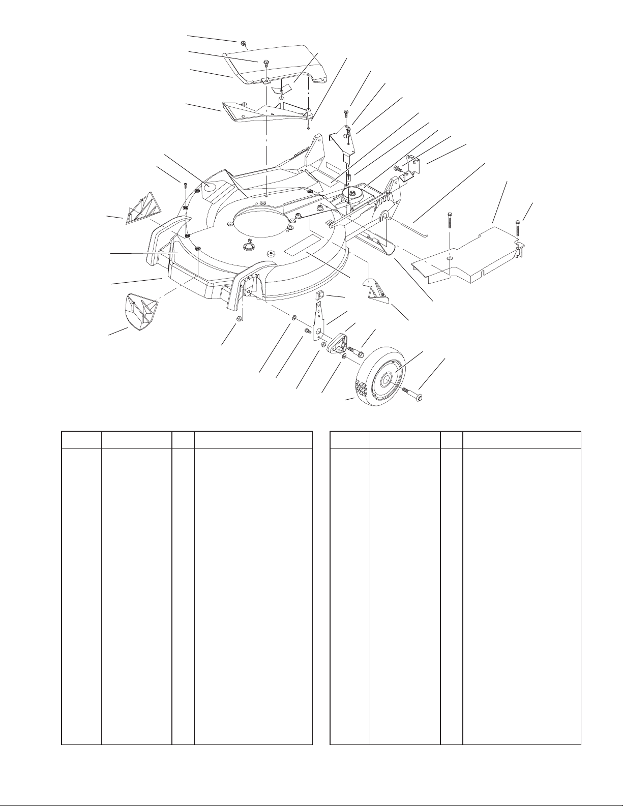
Housing and Wheel Assembly
DescriptionPart No. Qty.Ref. No. DescriptionPart No. Qty.Ref. No.
1 98–7130 2 Wheel ASM
1:1 27–6250 2 Bushing
2 40–1940 4 Washer
3 603773 2 Nut
4 32144–85 2 Screw–HH
5 3296–6 2 Nut–Lock, NI
7 98–7148 1 Housing – Service
7:2 92–1750 1 Kicker–Rear
7:3 92–1720 1 Kicker–Front
7:4 92–1730 1 Kicker–RH
7:5 32144–111 6 Screw–PPH
7:6 43–8480 1 Decal–Danger
7:7 93–0248 1 Decal – Warning
7:8 99–6018 1 Decal – Warning
8 99–6010 1 Decal – Deck
12 82–8620 1 Deflector
13 100–8775 1 Recycler Cover ASM
13:2 32144–111 5 Screw–PPH
14 46–6811 3 Screw–HWH
15 46–6810 1 Screw & Washer ASM
16 83–4750 1 Cover Guard
18 49–2040 1 Screw–Tapping
19 92–1616 1 Screw–HWHTF
20 99–1513–03 1 Bracket–Transmission
Actuator
22 614673 1 Bushing–Plate,
Actuator
23 104–7674 1 Gear Case ASM
24 32144–70 1 Screw–HH
25 99–1512–03 1 Bracket–Cable,
Traction
26 33–3208 1 Rod–Shield
27 104–7906 1 Cover–Belt
28 37–7260 1 Screw–HH
29 44–0580 1 Shield–Trailing
32 25–7740 2 Knob–Arm
33 66–0541 2 Front Spring Arm ASM
34 66–0580 2 Arm–Pivot, Front
35 66–0560 2 Bolt–Shoulder
36 92–1057 2 Bolt–Shoulder
3
3325–682
7
5
13
19
6
10
15
4
12
1
11
14
17
8
9
10
18
8
11
16
2
3
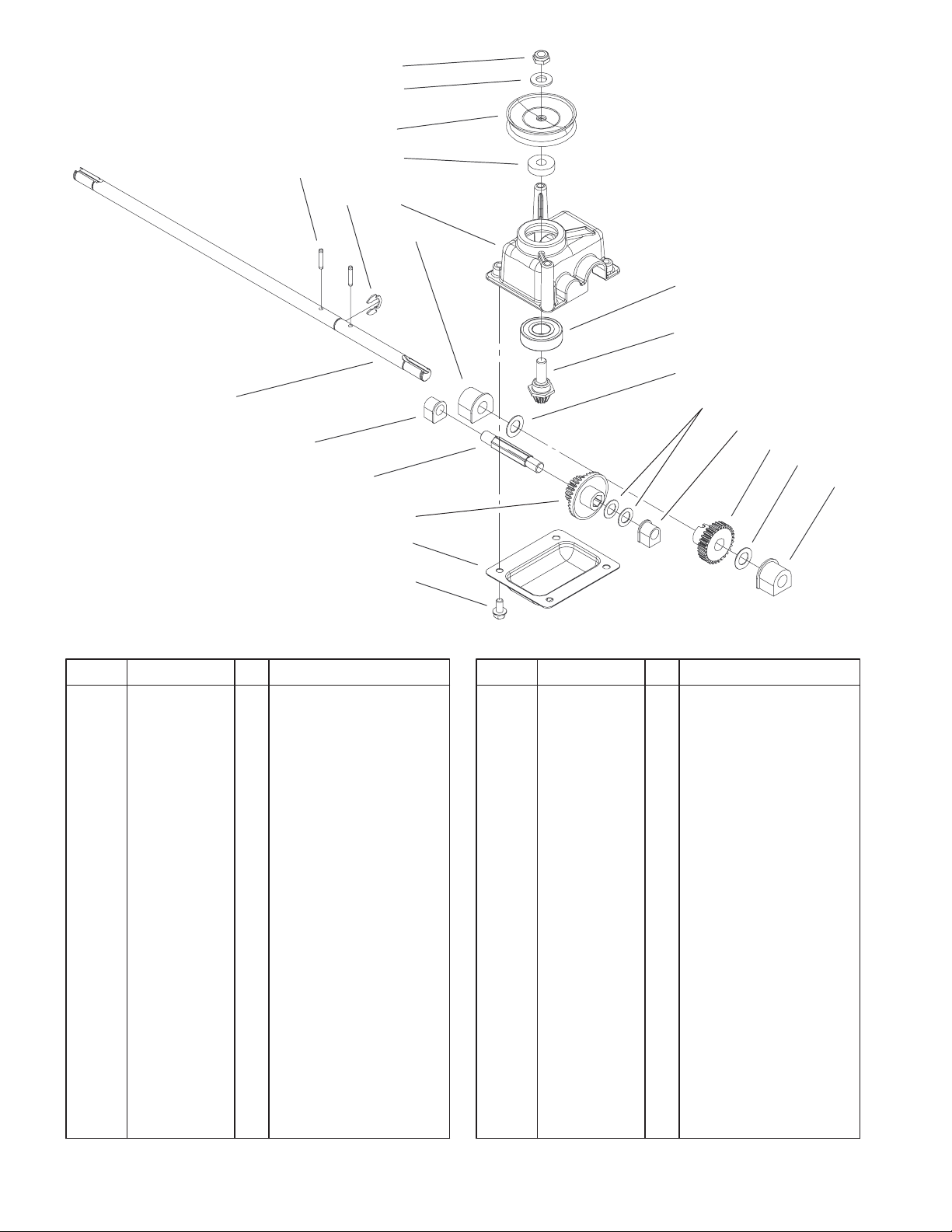
Gear Case Assembly 104–7674
DescriptionPart No. Qty.Ref. No. DescriptionPart No. Qty.Ref. No.
1 104–7619 1 Casting–Case, Gear
2 614668–03 1 Cover–Case, Gear
3 32144–4 4 Screw–HWH
4 32151–68 1 Ring–Retaining
5 3256–24 1 Washer–Flat
6 3285–19 2 Pin–Groove
7 3296–5 1 Nut–Lock NI
8 36–4780 2 Washer
9 36–4791 2 Washer–Thrust
10 60–8750 2 Bushing
11 60–8850 2 Bushing–Output
12 614696 1 Shaft–Intermediate
13 100–1176 2 Pulley–Half
14 100–1048 1 Bearing–Ball
15 62–6660 1 Spacer
16 104–1005 1 Gear–19t Spur, 37t
Bevel
17 104–7667 1 Gear–Pinion, Bevel
18 104–1004 1 Gear–30t
19 104–7673 1 Shaft–Output
Sheet No.:A1
4
3325–682
20
11
12
13
10
8:3
14
9
15
8:2
8
16
8:4
2X 4
17
2X 3
18
7
5, 6
19
2X 4
2X 3
2
2:1
Sheet No.:3
1
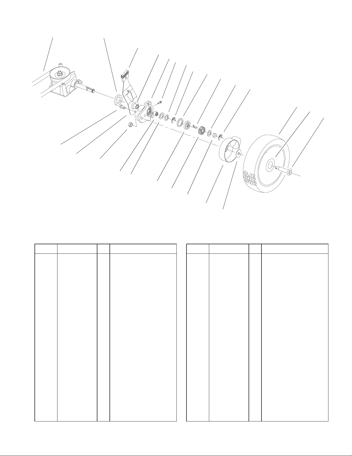
Gear Case and Wheel Assembly
DescriptionPart No. Qty.Ref. No. DescriptionPart No. Qty.Ref. No.
1 92–1057 2 Bolt–Shoulder
2 98–7135 2 Wheel ASM
2:1 27–6250 2 Bushing
3 65–2720 4 Ring–Klip
4 65–4740 4 Washer–Thrust,
Keyed
5 66–6040 1 Key–Rocking, RH
6 66–6050 1 Key–Rocking, LH
7 65–4710 2 Ring–Friction
8 100–8774 2 Pivot Arm ASM
8:2 47–2900 1 Bushing
8:3 70–9760 1 Bushing
8:4 302–56 1 Fitting–Zerk
9 25–7740 2 Knob–Arm
10 42–3520 2 Cap–End
11 32144–85 2 Screw–HH
12 63–8721 2 Spring Arm ASM
13 603773 2 Nut
14 65–4730 2 Washer–Arm, Pivot
15 65–4760 2 Washer–Clutch
16 65–4750 2 Gear–Pinion
17 65–4720 2 Spring–Compression
18 74–1660 2 Cover–Wheel
19 74–1671 2 Spacer–Cover, Wheel
20 91–2258 1 V–Belt
5
3325–682
6
5
7
8
10
11
3
12
4
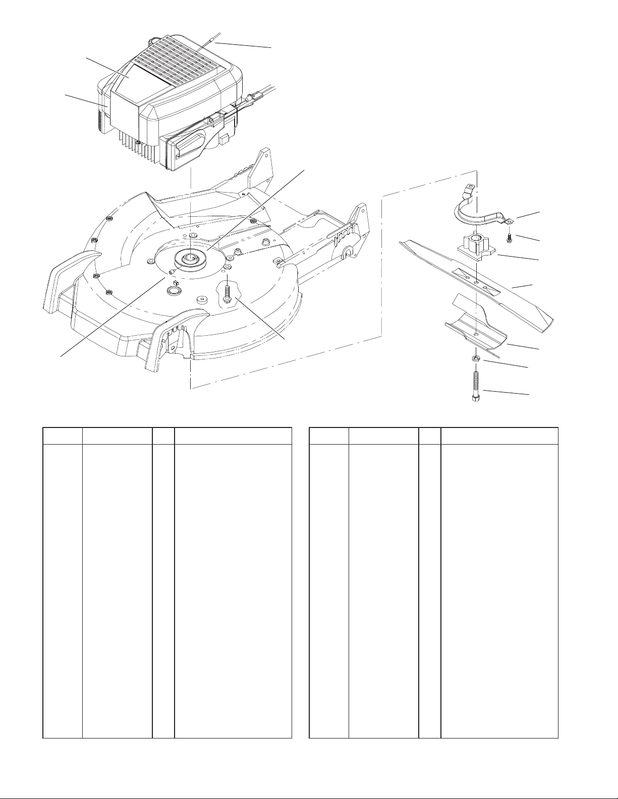
Engine and Blade Assembly
DescriptionPart No. Qty.Ref. No. DescriptionPart No. Qty.Ref. No.
1 3253–22 1 Washer–Lock
2 94–1608–03 1 Accelerator–Blade
3 104–1007 1 Retainer–Blade
4 104–0214 1 Screw–Set
5 1 Engine–Quantum Xl
Es,Zs, Briggs and
Stratton Model
12J805–2370–B1
6 99–6336 1 Decal – Recoil –
Quiet I/C
7 2210–316 1 Stop–Rope
8 95–1878 1 Pulley E
9 32144–102 3 Screw–HWH
10 66–0570–03 1 Bracket–Guide, Belt
11 32144–70 2 Screw–HH
12 93–4106–03 1 Blade–Recycler
13 95–1748 1 Screw–Blade
9
Sheet No.:6
2
1
13
6
 Loading...