

Page 1

KAWASAKI FC150V ENGINE MANUAL
Table of Contents – Page 1 of 3
GENERAL INFORMATION
MECHANICAL SYSTEM
ELECTRICAL SYSTEM
GENERAL SPECIFICATIONS
WIRING DIAGRAM
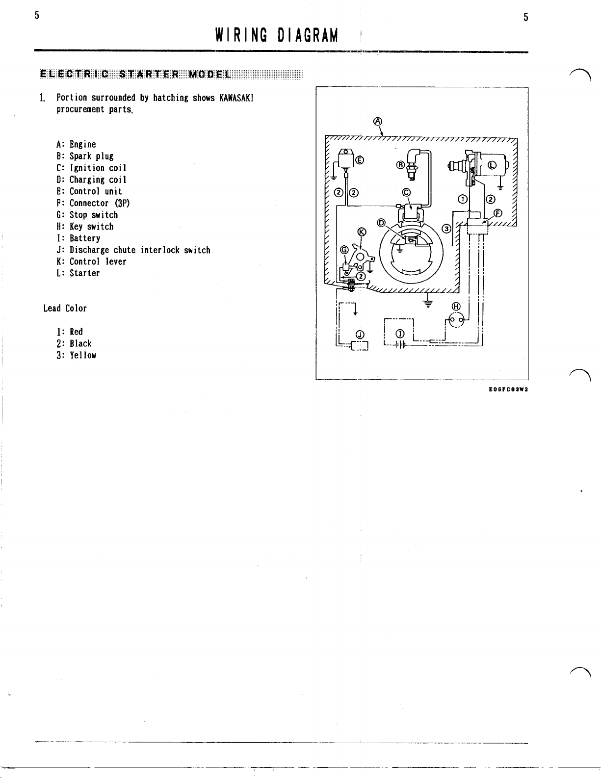
ELECTRIC STARTER MODEL
PERIODIC MAINTENANCE
TROUBLE SHOOTING
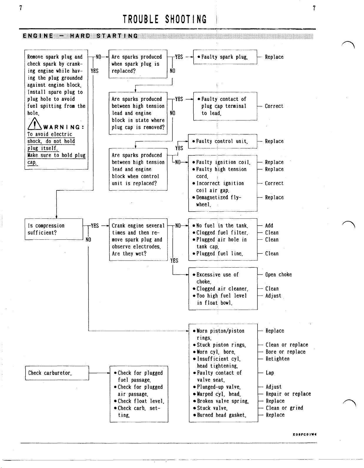
ENGINE - HARD STARTING
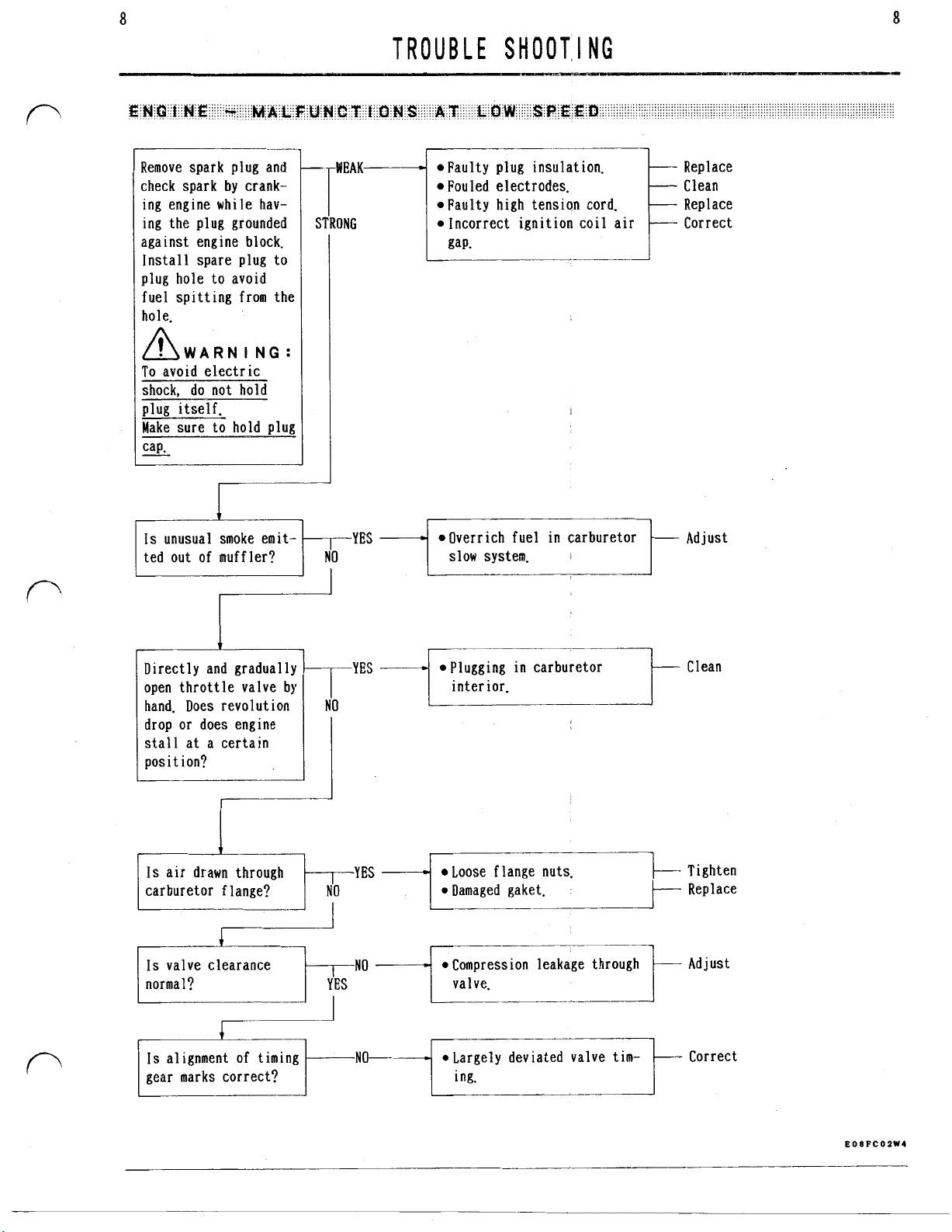
ENGINE - MALFUNCTIONS AT LOW SPEED
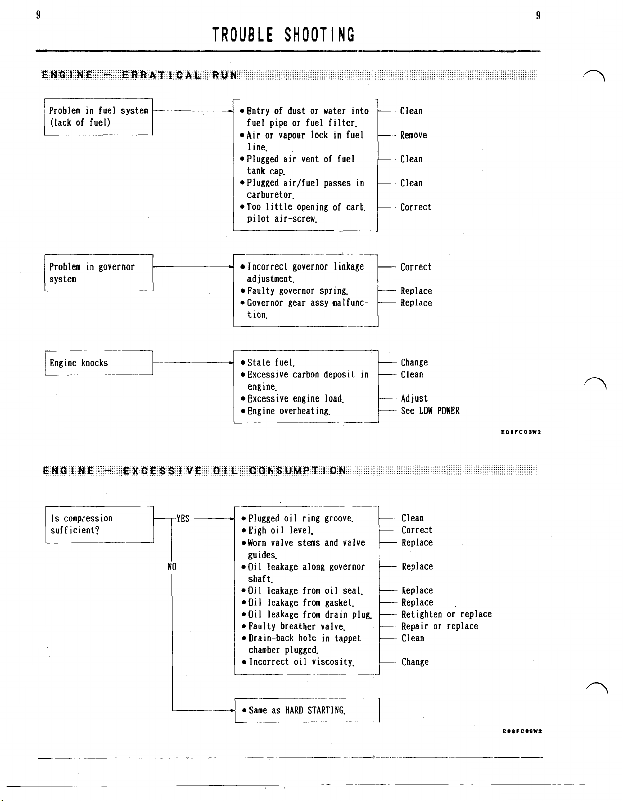
ENGINE - ERRATICAL RUN
ENGINE - EXCESSIVE OIL CONSUMPTION
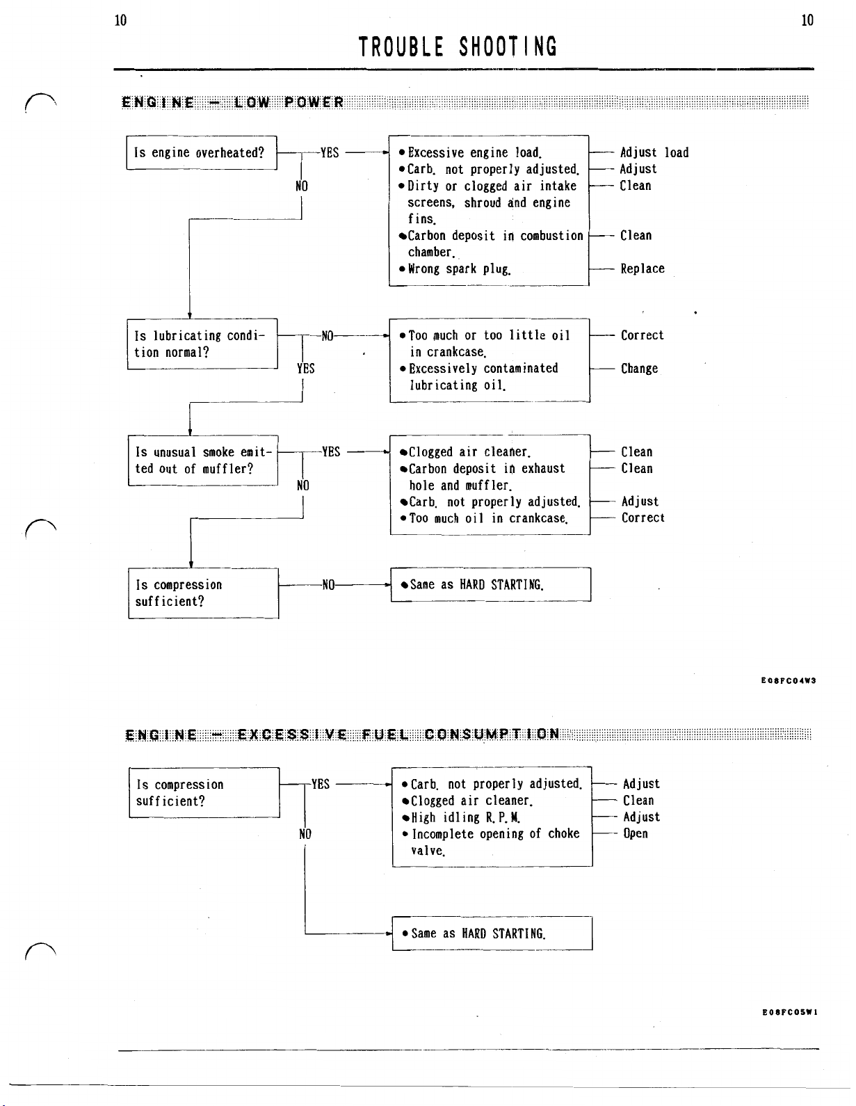
ENGINE - LOW POWER
ENGINE - EXCESSIVE FUEL CONSUMPTION
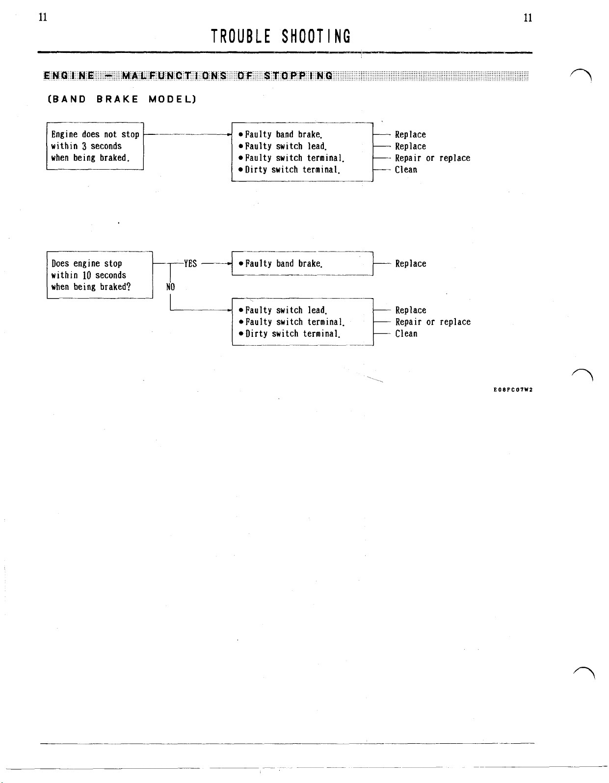
ENGINE - MALFUNCTIONS OF STOPPING
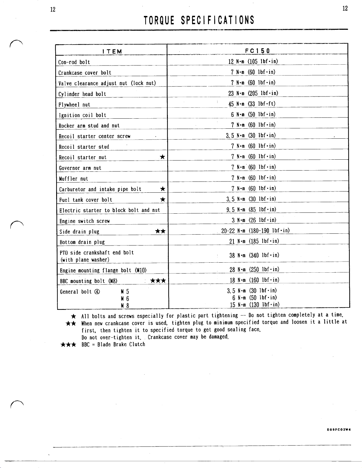
TORQUE SPECIFICATIONS
CONTROL SYSTEM
GOVERNOR LEVER SETTING
THROTTLE CABLE INSTALLATION
FAST IDLE SPEED ADJUSTMENT
CHOKE ADJUSTMENT
SLOW IDLE SPEED ADJUSTMENT
AIR CLEANER
"K" KLEEN SYSTEM
MAINTENANCE
CARBURETOR
COMPONENTS
REMOVAL
FLOAT CHAMBER REMOVAL
CLEANING
FLOAT ADJUSTMENT
ASSEMBLY AND INSTALLATION
CARBURETOR IDENTIFICATION
COOLING SYSTEM
ENGINE COVER REMOVAL
ENGINE COVER DISASSEMBLY
ENGINE COVER ASSEMBLY AND INSTALLATION
RECOIL STARTER
DISASSEMBLY
CHECK
REASSEMBLY
Page 2

KAWASAKI FC150V ENGINE MANUAL
Table of Contents – Page 2 of 3
ELECTRIC STARTER & CHARGING
TROUBLE SHOOTING
STARTER MOTOR CHECK
COMPONENTS
RING GEAR CHECK
STARTER MOTOR REASSEMBLY
STATOR OUTPUT
IGNITION SYSTEM
TYPE OF IGNITION SYSTEM
SPARK CHECK
CONTROL UNIT CHECK
IGNITION COIL CHECK
FLYWHEEL REMOVAL
FLYWHEEL INSTALLATION
IGNITION COIL AIR-GAP ADJUSTMENT
INTERMEDIATE CONNECTOR INSTALLATION
THROTTLE-LEVER-LINKED ENGINE SWITCH
BAND-BRAKE-LINKED ENGINE SWITCH
CYLINDER HEAD
COMPRESSION CHECK
REMOVAL
MAINTENANCE
INSTALLATION
VALVE
VALVE CLEARANCE ADJUSTMENT
AUTOMATIC COMPRESSION RELEASE (ACR) CHECK
VALVE AND RELATED PARTS REMOVAL
ROCKER ARM STUD INSTALLATION
CHECK AND MAINTENANCE
SERVICE LIMIT
VALVE SPRING SERVICE LIMIT
LAPPING
VALVE SEAT RECONDITIONING
VALVE GUIDE SERVICE LIMIT
ROCKER ARM SERVICE LIMIT
PUSH ROD SERVICE LIMIT
CRANKCASE COVER
REMOVAL
SERVICE LIMIT
OIL SEAL REPLACEMENT
INSTALLATION
Page 3

KAWASAKI FC150V ENGINE MANUAL
Table of Contents – Page 3 of 3
CAMSHAFT
REMOVAL
VISUAL CHECK
SERVICE LIMIT
INSTALLATION
PISTON & CON-ROD
REMOVAL
PISTON AND PISTON RING VISUAL CHECK
PISTON CLEANING
PISTON SERVICE LIMIT
PISTON PIN SERVICE LIMIT
PISTON RING SERVICE LIMIT
PISTON RING INSTALLATION
CON-ROD VISUAL CHECK
CON-ROD SERVICE LIMIT
PISTON AND CON-ROD ASSEMBLY
PISTON/CON-ROD ASSY INSTALLATION
CRANKSHAFT
VISUAL CHECK
SERVICE LIMIT
INSTALLATION
CRANK PIN RE-GRINDING
GOVERNOR
GOVERNOR GEAR CHECK AND REMOVAL
GOVERNOR GEAR INSTALLATION
GOVERNOR SHAFT INSTALLATION
LUBRICATING SYSTEM
ENGINE OIL
OIL SLINGER CHECK
BREATHER SYSTEM
BREATHER REED VALVE CHECK
CYLINDER/CRANKCASE
CYLINDER SERVICE LIMIT
CYLINDER BORE RE-SIZING
BALL BEARING CHECK
BALL BEARING REPLACEMENT
OIL SEAL REPLACEMENT
CAMSHAFT BEARING SERVICE LIMIT
BAND BRAKE
BAND BRAKE MECHANISM
BRAKE SHOE REPLACEMENT
BRAKE CABLE ADJUSTMENT
Page 4
4=stroke
air-cooled
gasoline
engine
WORKSHOP
MANUAL
Page 5
FOREWORD
This manual
nics in a properly equipped
In order to perform the work efficiently and to
avoid costly mistakes, read the text thoroughly,
familiarize yourself with the procedures before
starting work, and then do the work carefully in a
clean area. Whenever special tools
specified. do not use makeshift tools
Precision measurements can only be made if the proper instruments are used, and the use of substitute
tools may adversely affect safe operation.
Whenever you see these
T
I
0
Always follow safe operation and maintenance pract ices.
A
ual and on the equipment. When you see this symbol,
read the message that follows very carefully to
avoid fire, personal injury,
C
A
UT
or
procedures to avoid equipment damage
t ion.
N
0
T E :
interest for more efficient
is
designed for
N
symbols, heed their instructions!
W
A
R N I N
tifies important safety messages in this man-
I 0 N
Indicates message
G
:
:
This
identifies special instructions
use by trained mechashop.
or
equipments are
or
equipment.
W
A
R N I N
This safety alert symbol iden-
or
or
and convenient operat ion.
G
AND
C
A
U
loss
of life.
or
destruc-
points of particular
The term "Replace" and some abbreviations are used
as follows:
Replace
MIN
MAX
Assy
STD
PTO
Approx.
Carb.
Con-rod
Cyl.
Dia.
All
may be reproduced, stored in a retrieval system,
or
tronic mechanical photocopying, recording
wise. without the prior written permission of Engine
Division/Kawasaki Heavy Industries, Ltd.
ty can be accepted for any inaccuracies
in this publication, although every possible care
has been taken to make it as complete and accurate
as possible.
ject to change without prior notice
Illustrations in this publication are intended for
reference use only and may not depict actual model
component parts.
=
Usually means replace with a new part
=
Minimum
=
Maximum
=
Assembly
=
Standard
=
Power take off
=
Approximately (Approximate)
=
Carburetor
=
Connecting rod
=
Cylinder
=
Diameter
rights reserved.
transmitted in any form
All
procedures and specifications sub-
NO
part of this publication
or
by any means, elec-
or
other-
No
liabili-
or
omissions
or
obligation.
EOOFCOIW9
SAFETY
WA
R
W
A
R N I N
mable and can be explosive under certain con- sembly operations on the equipment with the
A
ditions. Stop the engine. Do not smoke. Make sure electric starter, disconnect the negative
the area
of flame
a pilot light.
the spark plug wire from the spark
accidental starting.
A
in servicing the product.
is
or
W A R
equipment, always stop the engine and remove
WARN I NG
or
a piece of thick cloth from edges and heat
G
:
Gasoline
is
extremely flam-
__--
well ventilated and free from any source lead from the battery to avoid the possibility of
sparks; this includes any appliance with accidentally cranking the engine while partially
disassembled.
N I N G
When servicing the engine
or
A
plug
to avoid
:
Protect your hands with gloves
in a clean. dry environment with dry hands. For maximum shock hazard protection, connect the equipment
ground terminal to an earth ground.
N I N G
W
A
R N I N G
when working on the electrical equipment. Work
:
Before performing any disas-
:
Always minimize shock hazards
EO1FC1W1
Page 6
TABLE
OF
CONTENTS
Page 7
PI STON
PI STON
PI STON
PI STON
1
STON
P
PI STON
GOVERNOR
GOVERNOR GEAR CHECK AND REMOVAL
GOVERNOR GEAR INSTALLATION
GOVERNOR SHAFT INSTALLATION
60
60
60
60
Page 8
1
1
GENERAL
Be famil iar with OPERATOR’
Lubrication
Supply engine oil as specified even for a short
test running to avoid any score
which may destroy the engine in the field use.
Use clean engine oil in the case specified as just
“coat oil” in this manual.
Don’ t use just any
greases
applications and may be harmful if used in an application for which they are not intended.
Engine wear
engine
surfaces have an adequate lubricative film. During
assembly, oil or grease (whichever
should be applied to any rubbing surface which has
lost its lubricative film. Old grease and dirty oil
should be cleaned off. Deteriorated grease has lost
its
foreign particles.
Fuel
Unleaded gasoline
of the less deposit in the combustion chamber.
Alcohol mixed gasoline
bad influences
in the fuel and combustion systems.
in
particular should be used only
is
is
warming up and before all the rubbing
lubricative quality and may contain abrasive
oil
generally at
is
of
alcohol on the engine components
S
MANUAL before service.
in
the engine,
or grease. Some
its
maximum while.the
preferably recommended because
is
not recommended due to
oils
and
in
certain
is
more suitable)
I
NFORMAT
Dirt
Before removal and disassembly, clean the product.
Any dirt entering the product, carburetor, or other
parts will work as an abrasive and shorten the life
of the product. For the same reason, before install-
ing
a
Liquid Gasket and Non-permanent Locking Agent
Follow manufacturer’s directions for cleaning and
preparing surfaces where these compounds wi
used. Apply sparingly. Excessive amounts may block
engine oil passages and cause serious damage. An
example of a non-permanent locking agent commonly
available in
(Blue).
Oil Seal, Grease Seal
Replace any oil or grease seals that were removed,
because the removal generally damages seals.
A seal guide
seals during installation
seal lips.
Gasket, 0-r
When
O-ring, replace
gasket should be free from foreign matter and smooth
to avoid leakage.
I
ON
new part,
in
doubt as to the condition of a gasket or
’
clean off any dust
North
America
is
required for certain oil or grease
ing
it.
The mating surfaces around the
or
metal fillings.
11
be
is
Loctite Lock’n Seal
to
avoid damage to the
High Flash-point Solvent
A
high flash-point solvent
fire danger.
in
North America
Always follow manufacturer’s and container’s directions regarding the use of any solvent.
A
commercial solvent commonly available
is
Stoddard solvent (generic name).
is
recommended to reduce
Circl ip, Retaini,ng Ring
Replace any circlips and retaining rings that were
removed, because the removal weakens and deforms
them. When installing circlips and retaining rings,
take care to compress or expand them only enough to
install them.
Page 9
2
2
GENERAL
Force
Common sense should dictate how much force
sary in assembly and disassembly.
especially difficult to remove
check what may be causing the problem. Whenever tapping
is
necessary, tap lightly using a wooden or
plastic-faced mallet. Use an impact driver for
screws (particularly for the removal of screws held
by a locking agent) in order to avoid damaging the
heads.
Press
A
part, such as a seal, installed using a press or
driver should first be coated with oil on
.or inner surface
smoothly.
Ball Bearing Installation
When installing a ball bearing, the bearing race
which
is
affected by friction should be pushed by a
suitable driver. This prevents severe stress on the
balls and races, and prevents races and balls from
being dented. Press a ball bearing until it stops
at the stop
so
that
it
in
the hole or on the shaft.
If
or
install, stop and
will go into place
is
neces-
a part seems
its
outer
I
NFORMAT
Torque
The torque values given
always be adhered to. Either too little or too much
torque may lead to serious damage. Use a good quality, reliable torque wrench.
Tightening Sequence
follow
When installing a part with several bolts, nuts or
screws, they should all be started in their holes
and tightened to
evenly, according to the tightening sequence, to
the specified torque.
of the part and/or leakage. Conversely, when loosen-
ing the bolts, nuts,
about a quarter of a turn and then remove them.
I
ON
the
tightening sequence shown
a
snug fit. Then tighten them
in
this manual should
in
this manual.
This
is
to avoid distortion
or
screws, loosen all of them
EOSPCOIW7
Page 10
3
3
GENERAL
No
Shock
The electrical parts should never be sharply struck,
with a hammer, or dropped on a hard surface. Such
a shock to the parts may damage them.
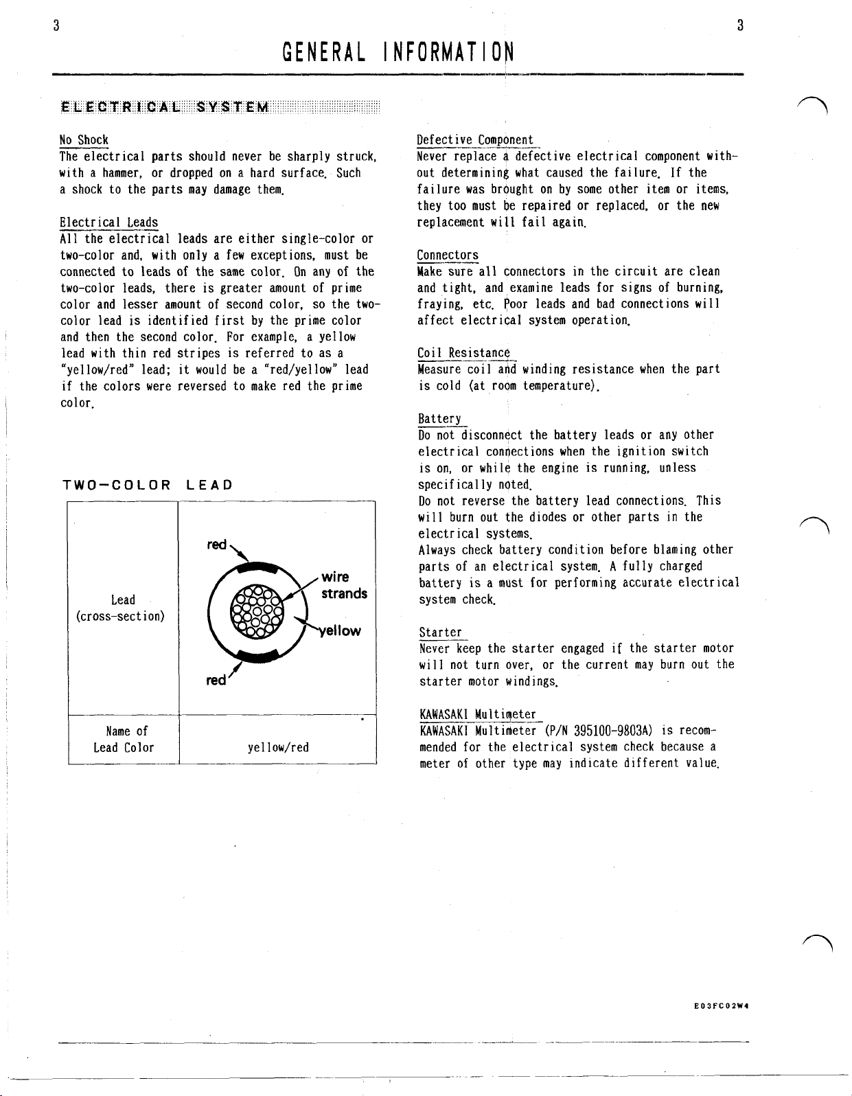
Electrical Leads
All
the electrical leads are either single-color or
two-color and,
connected to leads of the same color. On any of the
two-color leads, there
color and lesser amount of second color,
color lead
and then the second color. For example, a yellow
lead with thin red stripes
“yellow/red” lead;
if the colors were reversed to make red the prime
color.
TWO-COLOR
(cross-sect ion)
with
only a few exceptions,
is
greater amount of prime
is
identified first by the prime color
is
referred to as a
it
would be a “red/yellow” lead
LEAD
must
so
the two-
red
Lead
red’
I
NFORMAT
Defective Component
Never replace
out determining what caused the failure. If the
failure was brought on by some other item or items,
they too must be repaired or replaced, or the new
replacement
be
Connectors
~-
Make sure all connectors in the circuit are clean
and tight, and examine leads for signs of burning,
fraying, etc. Poor leads and bad connections will
affect electrical system operation.
Coil Resistance
Measure coil add winding resistance when the part
is
cold (at room temperature).
Battery
~-
Do
not disconnect the battery leads or any other
electrical connections when the ignition switch
is
on, or while the engine
specifically noted.
Do
not reverse the battery lead connections.
will burn out the diodes or other parts
electrical systems.
Always check battery condition before blaming other
parts of an electrical system.
battery
system check.
Starter
Never keep the starter engaged if the starter motor
will not
starter motor windings.
I
ON
a
will
is
a must for performing accurate electrical
turn
over, or the current may burn out the
defective electrical component with-
fail again.
is
running, unless
This
in
the
A
fully charged
Name of
Lead Color
ye
1
1
ow/red
KAWASAKI
KAWASAKI
mended for the electrical system check because a
meter of other type may indicate different value.
MultimeterMultimeter
(P/N
395100-9803A)
is
recom-
Page 11
4
4
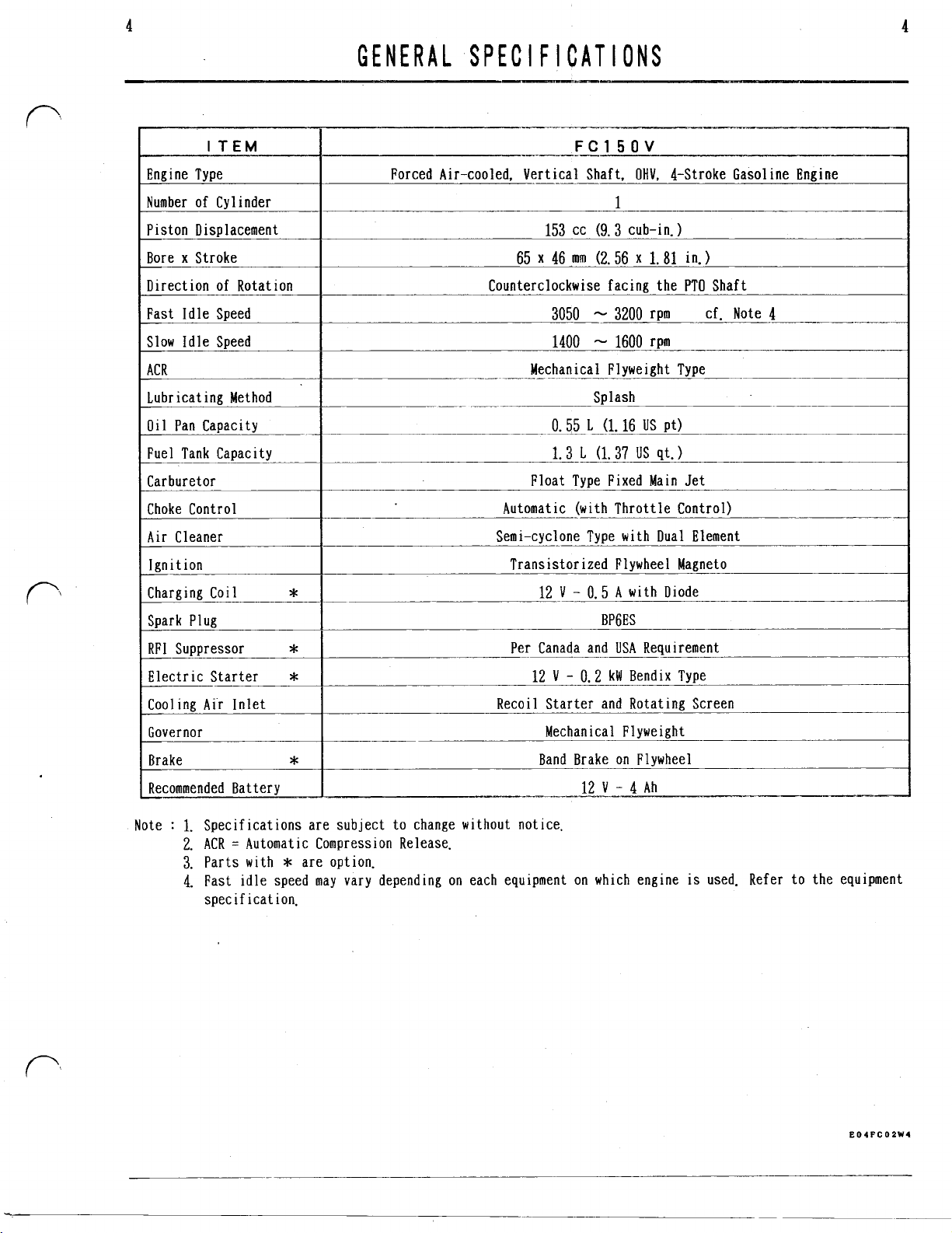
Number of Cylinder
Oil
Pan Capacity
GENERAL SPEC
I F I
CAT
I
ONS
~__=.-
Automatic (with Throttle Control)
FC15OV
1
3200
rpm cf. Note
Mechanical Flyweight Type
0.55
L
(1.16
US
Pt)
1.
3
g.
37
us
qt.
4
Note
:
one Type with Dual Element
ransistorized Flywheel Magneto
V
0.5
A
with Diode
Per Canada and USA Requirement
12
V
0.2
kW
Bendix Type
Mechanical Flyweight
Band Brake on Flywheel
1.
Specifications are subject to change without notice.
2.
ACR = Automatic Compression Release.
3.
Parts with * are option.
is
4.
Fast idle speed may vary depending on each equipment on which eng
specification.
ine
used. Refer to the equ
ipment
Page 12
5
5
1.
Portion surrounded
procurement parts.
A:
Engine
B:
Spark plug
C: Ignition coil
D:
Charging coil
E:
Control unit
P:
Connector
G:
Stop switch
H:
Key switch
I:
Battery
J:
Discharge chute interlock switch
K:
Control lever
1:
Starter
Lead Color
by
(3P)
WIRING DIAGRAM
hatching shows
KAWASAKI
1
E.
1:
Red
2:
Black
3:
Yellow
E06PC09W2
Page 13
6
PER
I
OD
I
C
MA
I
NTENANCE
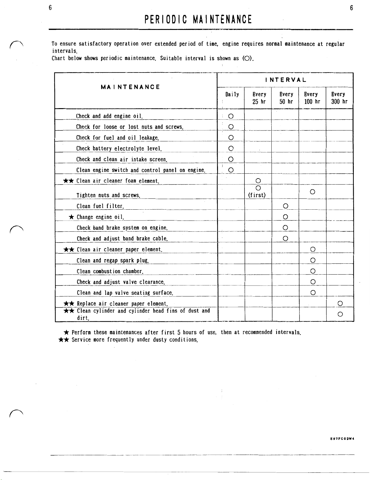
To ensure satisfactory operation over extended period of time, engine requires normal maintenance at regular
intervals.
Chart below shows periodic maintenance. Suitable interval
MAINTENANCE
is
shown as
Daily
(0).
Every
25
I
NTERVAL
Every
hr
50
Every
100
hr
Every
300
6
Check and add engine oi
Check for loose
Check for fuel and oil leakage.
Check battery electrolyte level.
Check and clean air intake screen.
Clean engine switch and control panel on engine.
**
Clean air cleaner foam element.
Tighten nuts and screws.
Clean fuel filter.
*
Change engine oil.
Check band brake system on engine.
Check and adjust band brake cable.
**
Clean air cleaner paper element.
Clean and regap spark plug.
Clean combustion chamber.
Check and adjust valve clearance.
or
1.
lost nuts and screws
(first)
Clean and lap valve seating surface.
**
Replace air cleaner paper element.
**
Clean cylinder and cylinder head fins of dust and
Ir Perform these maintenances after first
**
Service more frequently under dusty conditions.
5
hours of use, then at recommended intervals.
Page 14
7
7
I
Remove spark plug and
check spark by crank-
ing engine while having the plug grounded
against engine block.
Install spare plug to
plug hole to avoid
fuel spitting
ha le.
Make sure to hold plug
from
YES
the
Are sparks produced
when spark plug
lead and engine
block
plug cap
Are sparks produced
between high tension
lead and engine
block when control
unit
TROUBLE
in
state where
is
removed?
is
replaced?
SHOOTING
is
elty
I
spark plug. Replace
plug cap terminal Correct
Faulty high tension Rep1 ace
Incorrect ignition Correct
Is
compression
sufficient?
Check carburetor.
Demagnetized fly- Rep ace
Rep lace
I.---
Crank engine several
times and then remove spark plug and
observe electrodes.
Are they wet?
’
YES
*No
fuel in the tank.
*Clogged fuel filter. Clean
.Plugged air hole in Clean
tank cap.
*Plugged fuel line. Clean
Excessive use of
Clogged air cleaner.
*Too
high fuel level
in float bowl.
Open choke
Clean
Adjust
~_-
Worn piston/piston
ings.
*Stuck piston rings.
Worn cyl. bore.
Insufficient cyl.
head tightening.
I-
*Check for plugged
fuel passage.
.Check
for
plugged
air passage,
Check float level.
Check carb. set-
t
ing.
*Faulty contact of Lap
valve seat.
Plunged-up valve.
Warped cyl. head.
Broken valve spring. Replace
Stuck valve. Clean
Burned head gasket.
Replace
Clean
or
replace
Bore
or
replace
Retighten
Adjust
Repair
Replace
or
replace
or
grind
EOOPCOIW4
Page 15
8
8
I
Remove spark plug and
check spark by crank-
ing engine while having the plug grounded
against engine block.
Install spare plug to
plug hole to avoid
fuel spitting from the
hole.
To avoid electric
shock, do not hold
plug itself.
Make sure to hold plug
cap.
STRONG Incorrect ignition coil air Correct
TROUBLE
Faulty plug insulation.
Fouled electrodes.
*Faulty high tension cord. Rep
SHOOT,I
NG
1
ace
Is
unusual smoke emit-
ted out of muffler?
Directly and gradually
open throttle valve by
hand. Does revolution
drop or does engine
stall at a certain
position?
Is
air drawn through
carburetor flange?
Is
valve clearance Compression leakage through
NO
YES
NO
*
Overrich fuel
slow system.
I
*Plugging in carburetor
interior.
Loose flange nuts. Tighten
Damaged gaket. Replace
in
carburetor Adjust
Clean
Is
alignment
of
timing
EOBPCOZW4
Page 16
9
9
Problem
system
in
governor
TROUBLE
.Entry of dust
fuel pipe
.Air
1
ine.
*Plugged air vent of fuel Clean
tank cap.
*Plugged air/fuel passes in Clean
carburetor.
.Too
pilot air-screw.
Incorrect governor linkage Correct
adjustment.
Faulty governor spring. Rep 1 ace
Governor gear assy malfunc- Replace
t
ion.
SHOOT
or
or
vapour lock in fuel Remove
little opening of carb. Correct
I
NG
or
fuel filter.
Engine knocks
NO
Stale fuel.
Excessive carbon deposit
engine.
Excessive engine load.
Engine overheating. See LOW
.Plugged oil ring groove. C 1 ean
.High
oil
level. Correct
.Worn valve stems and valve Replace
guides.
.Oil
leakage along governor Rep1 ace
shaft.
.Oil leakage from oil seal.
*Oil
leakage from gasket.
.Oil leakage from drain plug. Retighten
Faulty breather valve. Repair
.Drain-back hole
chamber plugged.
Incorrect oil viscosity. Change
in
in
tappet
Change
Clean
Adjust
POWER
1
ace
Rep
Replace
or
Clean
or
replace
replace
Same as
HARD
STARTING.
I
EOIFCOBV?
Page 17
10
10
Is
unusual
ted out of
TROUBLE
~Carb. not properly adjusted. Adjust
*Dirty or clogged air intake Clean
screens, shroud and engine
fins.
Carbon deposit
chamber.
*Wrong spark plug. Rep
NO--
I
*Too much or too little oil Correct
in crankcase.
Excessively contaminated Change
lubricating oil.
Clogged air cleaner. Clean
Carbon deposit
hole and muffler.
Carb. not properly adjusted. Adjust
SHOOT
I
NG
in
combust ion Clean
I
io
exhaust Clean
Adjust load
1
ace
Correct
Same as
sufficient?
sufficient?
Is
compress ion *Carb. not properly adjusted. Adjust
Clogged air cleaner. Clean
High id1 ing
Incomplete opening
valve.
HARD
STARTING.
R.
P.M.
___-
of
choke Open
Adjust
EOBFCO4W3
Page 18
11
11
TROUBLE
(BAND BRAKE MODEL)
Engine does not stop
3
within
when being braked.
I
Does engine stop -+Faulty band brake.
within
when being braked?
seconds
10
seconds
I
*Faulty band brake.
.Faulty switch lead.
Faulty switch terminal.
Dirty switch terminal. Clean
Faulty switch lead. Replace
*Faulty switch terminal.
Dirty switch terminal. Clean
SHOOT
I
NG
Rep
1
ace
1
ace
Rep
Repair or replace
Rep
1
ace
Repair or replace
E08PC07W2
Page 19
12
12
I
Governor arm nut
TORQUE
SPEC
I
F
I
CAT
I
ONS
12
N-m
7
N.m
7
N-m
23
N-m
45
N-m
6
N-m
7
N-m
3.5
N-m
7
N-m
7
N-m
7
N.m.(60 lbf-in
7
N-m
7
N-m
FC150
(105
lbf-in
(60
lbf-in
(60
lbf-in)
(205
lbf-in)
(33
lbf -ft)
(50
lbf-in)
(60
lbf-in)
(30
lbf-in)
(60
lbf-in)
(60
lbf-in)
(60
lbf-in)
(60
lbf-in)
__.___..___
3.5
N.m
(30
9.5
N-m
(85
3
N-m
(26
20-22
N-m
Side drain plug
21
(with plane washer)
Engine mounting flange bolt
BBC mounting bolt (M8)
General bolt
(M10)
38
28
18
3.5
15
j,
All bolts and screws especially for plastic part tightening
**
***
When new crankcase cover
first, then tighten it to specified torque to get good sealing face.
Do
not over-tighten it. Crankcase cover may be damaged.
BBC = Blade Brake Clutch
is
used, tighten plug to minimum specified torque and loosen it a little at
(180-190
N-m
(185
N-m
(340
N-m(250 lbf-in
N-m
(160
N-m
(30
6
N-m
(50
N-m
(130
Do
lbf-in
lbf .in)
lbf-in
lbf-in)
lbf-in)
lbf-in)
lbf-in
lbf-in)
Ibf-in)
lbf-in
not tighten completely at a time.
E09FCOZW4
Page 20
13
13
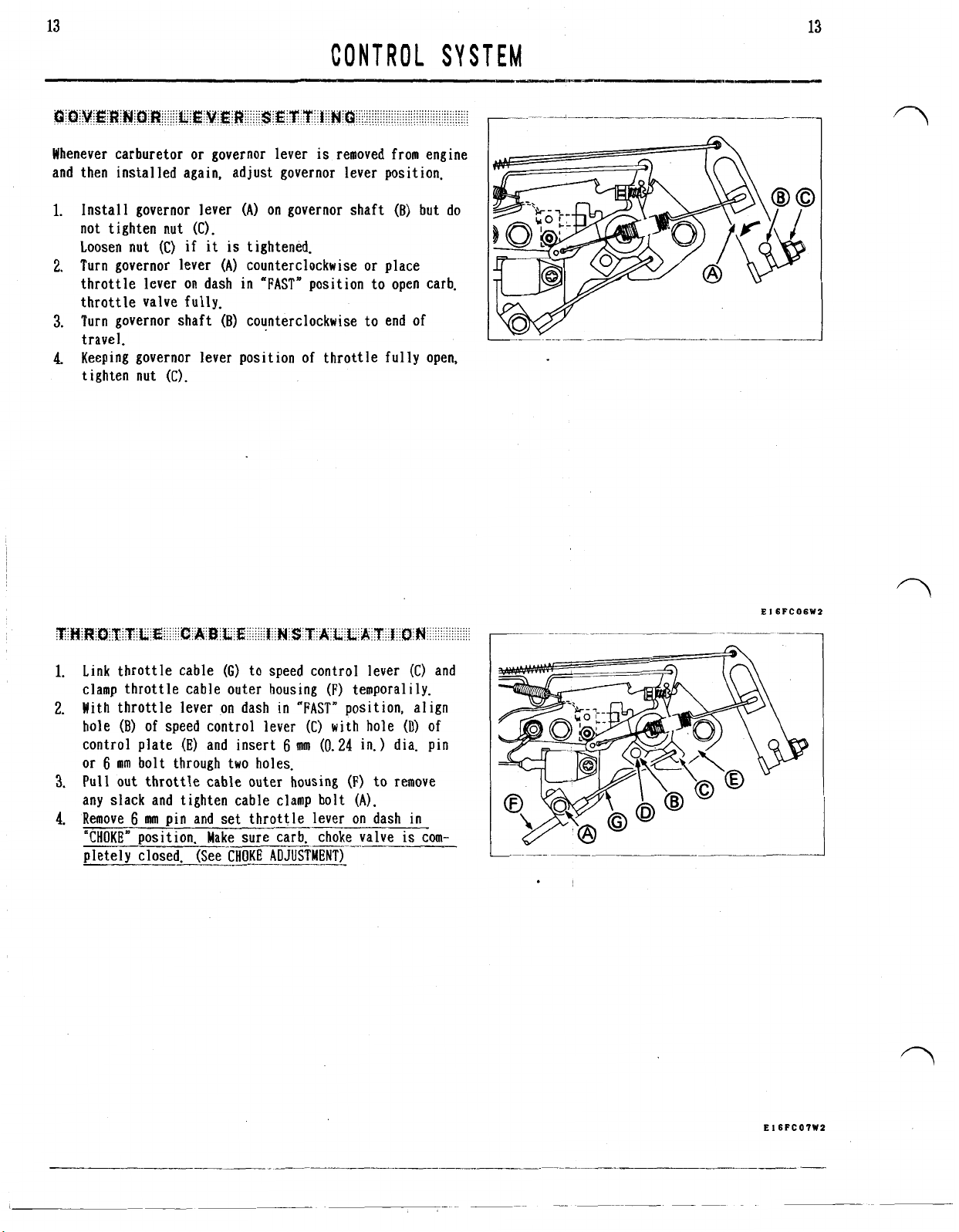
Whenever carburetor
or
governor lever
CONTROL
is
removed from engine
SYSTEM
and then installed again. adjust governor lever position.
Install governor lever
on governor shaft
(B)
but do
(A)
not tighten nut (C).
(C)
Loosen nut
Turn governor lever
throttle lever on dash in
if it is tightened.
(A)
counterclockwise
"FAST*
position to open carb.
or
place
throttle valve fully.
Turn governor shaft
(B)
counterclockwise to end
of
travel.
Keeping governor lever position of throttle fully open,
tighten nut
(C).
Link throttle cable
clamp throttle cable outer housing
(G)
to speed control lever
(F)
temporalily.
(C)
and
With throttle lever on dash in "FAST" position, align
hole
(B)
of
speed control lever
control plate
or
6
mm bolt through two holes.
Pull
out throttle cable outer housing
(E)
and insert 6 mm
any slack and tighten cable clamp bolt
(C)
with hole
(0.24
in.) dia. pin
(F)
to remove
(A).
(D)
of
Remove 6 mm pin and set throttle lever on dash in
is
"CHOKE* position. Make sure carb. choke valve
~~
corn-
pletely closed. (See CHOKE ADJUSTMENT)
E
I6FCO6W2
E
16FCO?W2
Page 21
14
14
CONTROL
NOT
E
:
Air cleaner must be installed to engine before
starting.
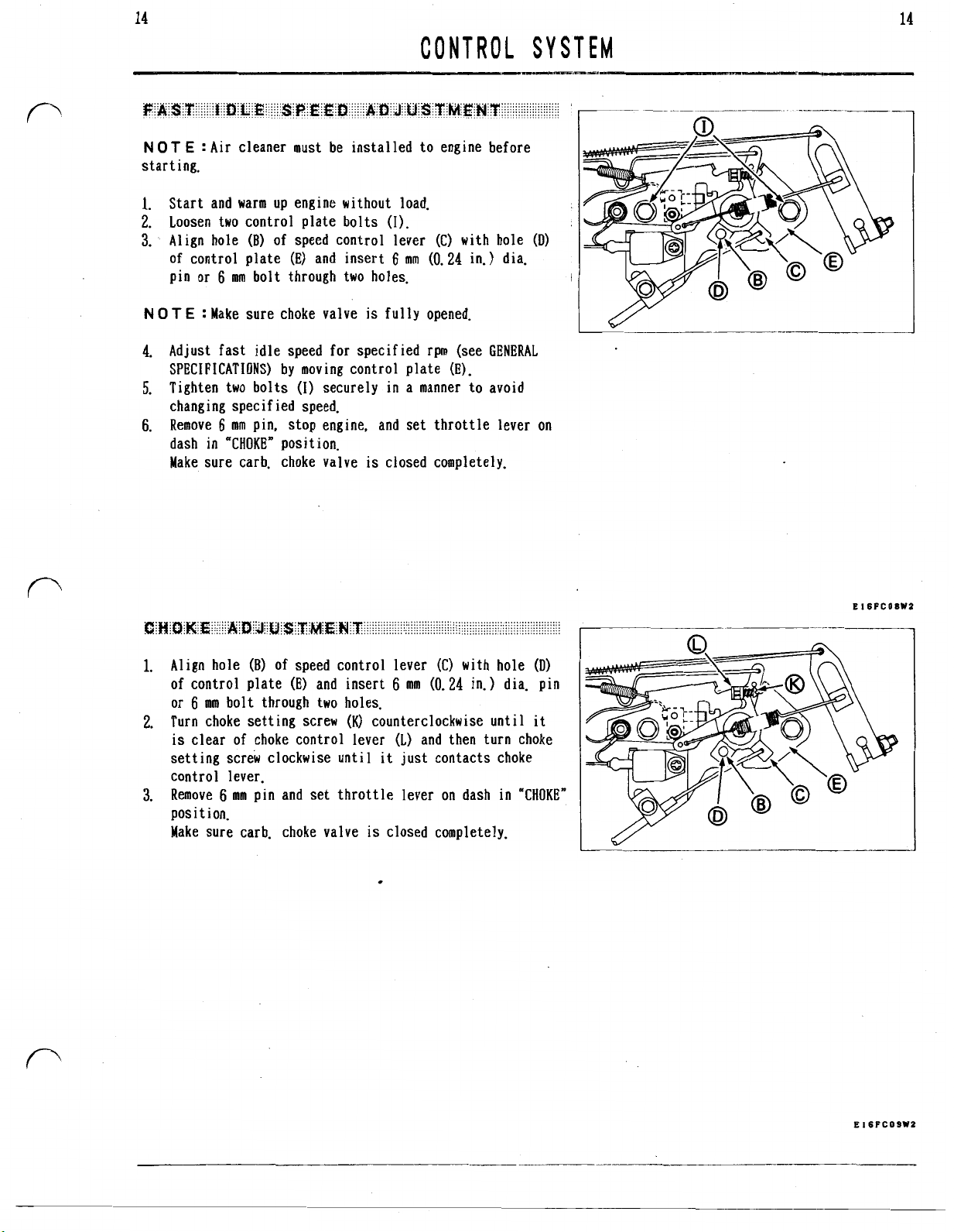
1.
Start and warm up engine without load.
2.
Loosen two control plate bolts
3.
Align hole
of control plate (E) and insert 6 mm
pin or
NOT
E
4.
Adjust fast idle speed for specified rpm (see GENERAL
SPECIFICATIONS) by moving control plate (E).
5.
Tighten two bolts
changing specified speed.
6.
Remove 6 mm pin, stop engine, and set throttle lever on
dash in "CHOKE" position.
Make sure carb. choke valve
(B)
of
speed control lever (C) with hole
6
mm bolt through two holes.
:
Make sure choke valve
(I)
securely in a manner to avoid
(I).
(0.24
in.) dia.
is
fully opened.
is
closed completely.
SYSTEM
(I))
!
1.
Align hole
of control plate
or
6
2.
Turn choke setting screw
is
clear of choke control lever
setting screw clockwise until it just contacts choke
control lever.
3.
Remove 6 mm pin and set throttle lever on dash
posit ion.
Make sure carb. choke valve
(B)
of
speed control lever (C) with hole
(E)
and insert
mm bolt through two holes.
6
mm
(0.24
in.) dia. pin
(K)
counterclockwise until it
(1)
and then turn choke
is
closed completely.
(D)
in
"CHOKE"
E16PCOSWZ
Page 22
15
15
CONTROL
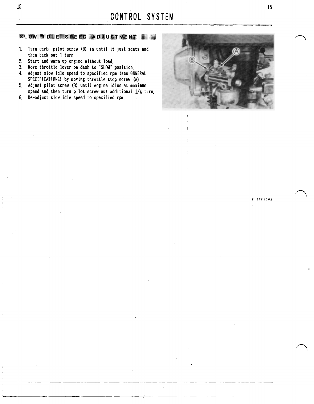
1.
Turn carb. pilot screw
then back out
2.
Start and warm up engine without load.
3.
Move throttle lever on dash to "SLOW" position.
4.
Adjust slow idle speed to specified rpm (see GENERAL
SPECIFICATIONS) by moving throttle stop screw (A).
5.
Adjust pilot screw
speed and then turn pilot screw out additional
6.
Re-adjust slow idle speed to specified rpm.
1
turn.
(B)
in until it just seats and
(B)
until engine idles at maximum
SYSTEM
1/4
turn.
E
I6FC
I
OW2
Page 23
16
16
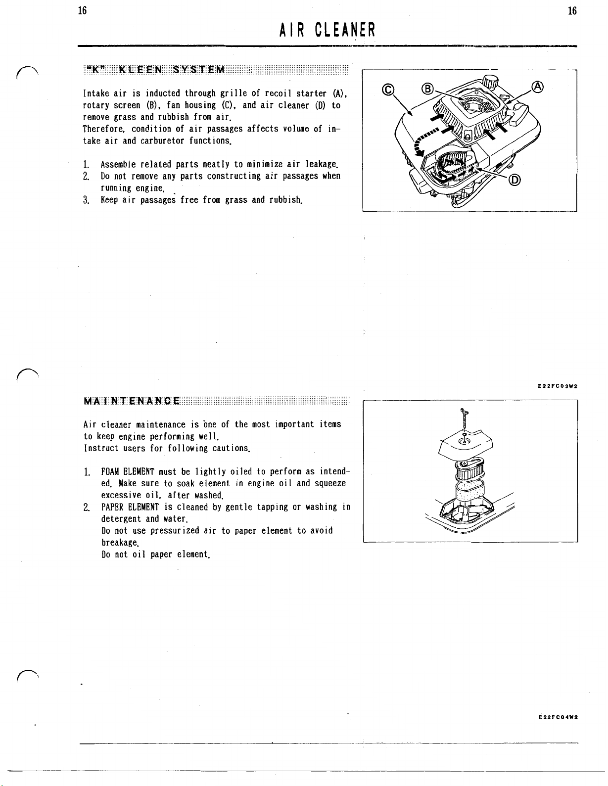
AIR
1.
Assemble related parts neatly to minimize air leakage.
2.
Do
not remove any parts constructing air passages when
running engine.
3.
Keep air passages free from grass and rubbish.
CLEANER
Air cleaner maintenance
to keep engine performing well.
Instruct users for following cautions.
1.
FOAM
ELEMENT
ed. Make sure to soak element
excessive oil, after washed.
2.
PAPER
ELEMENT
detergent and water.
Do
not use pressurized air to paper element to avoid
breakage.
Do
not oil paper element.
must be lightly oiled to perform as intend-
is
one of the most important items
in
engine oil and squeeze
is
cleaned by gentle tapping
or
washing in
E22FC03W2
E22FCO4W2
Page 24

17
17
CARBURETOR
This carburetor
(idle mixture) and fixed main jet.
NOT
E
:
conf igulation.
is
float type with adjustable pilot screw
Refer to each parts catalog for detailed parts
10
E24FC08WS
Page 25

18
W A R
N I
N
G
:
Gasoline
Avoid fires due to smoking or careless practices.
1.
Shut fuel valve.
2.
Drain fuel from float chamber.
3.
Disconnect fuel line
fuel line opening immediately
into suitable container.
4.
Disconnect breather tube
5.
Disconnect adaptor
6.
Remove bolts
c
A
UT
0
N
:
Do not lose collars in intake pipe bolt
holes.
(D)
(E).
is
extremely flammable.
(C)
from carburetor. Plug the
or
drain fuel
(A)
from intake pipe
from intake pipe
CARBURETOR
in
the line
(B).
(B).
18
Unhook throttle rod
7.
(GI.
lever
Unhook choke rod
8.
lever
(J).
(E)
and rod spring
(H)
and choke rod spring
(F)
from throttle
(I)
from choke
E24FCOSW3
Page 26
19
19
CARBURETOR
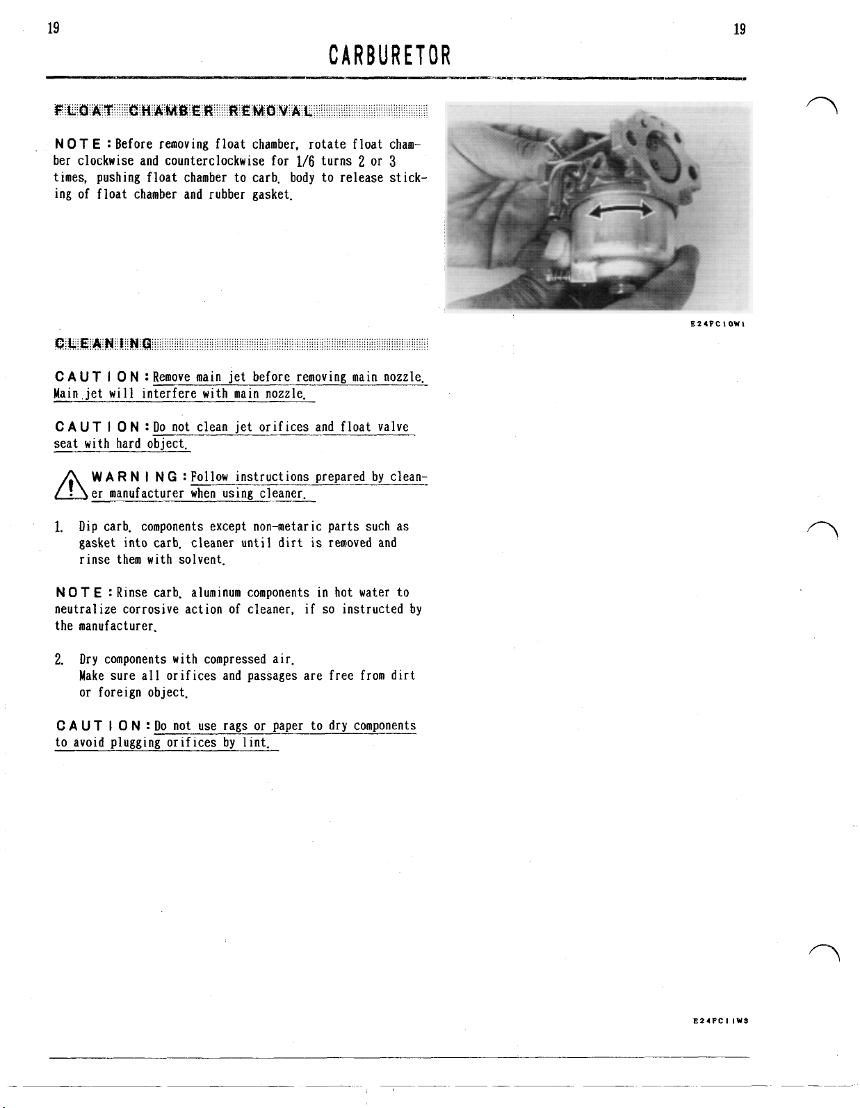
N 0 T E :
ber clockwise and counterclockwise for
Before removing float chamber, rotate float cham-
1/6
turns 2 or
3
times, pushing float chamber to carb. body to release stick-
ing
of
float chamber and rubber gasket.
C
A
UT
I
0
N
:
Remove main jet before removing main nozzle.
Main iet will interfere with main nozzle
C
A
UT
I
0
N
:
Do not clean jet orif ices and float valve
seat with hard object.
W
A
R
N I N
G
:
Follow instructions prepared by clean-
er manufacturer when using cleaner.
1.
Dip
carb. components except non-metaric parts such as
is
gasket into carb. cleaner until dirt
removed and
rinse them with solvent.
E24FCIOWI
NOT
E
:
Rinse carb. aluminum components
neutralize corrosive action of cleaner, if
in
hot water to
so
instructed by
the manufacturer.
2.
Dry components with compressed air.
Make sure all orifices and passages are free from dirt
or foreign object.
C
A
U
T I 0 N
:
Do
not use rags or paper to dry components
to avoid plugging orif ices by lint.
E24FCI
1W3
Page 27
20
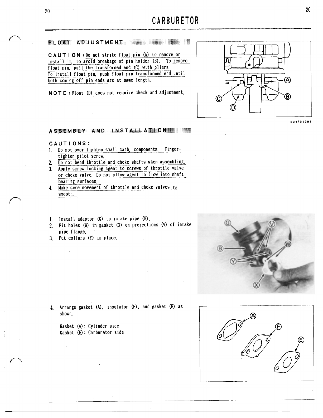
C A UT
install
I
0 N :
Do
not strike float pin
it,
to avoid breakage of pin holder
(A)
to remove or
(B).
To
remove
float pin, pull the transformed end (C) with pliers.
To
install float pin, push float pin transformed end until
both coming off pin ends are at same length.
NOT
E
:
Float
(D)
does not require check and adjustment.
I I
CAUT I
1.
ONS:
Do
not over-tighten small carb. components. Finger:
tighten pilot screw.
2.
Do
not bend throttle and choke shafts when assembling.
3.
Apply screw locking agent to screws of throttle valve
Do
or choke valve.
not allow agent to flow into shaft
bearing surf aces.
4.
Make sure movement of throttle and choke valves
is
smooth.
EZIFCIZWI
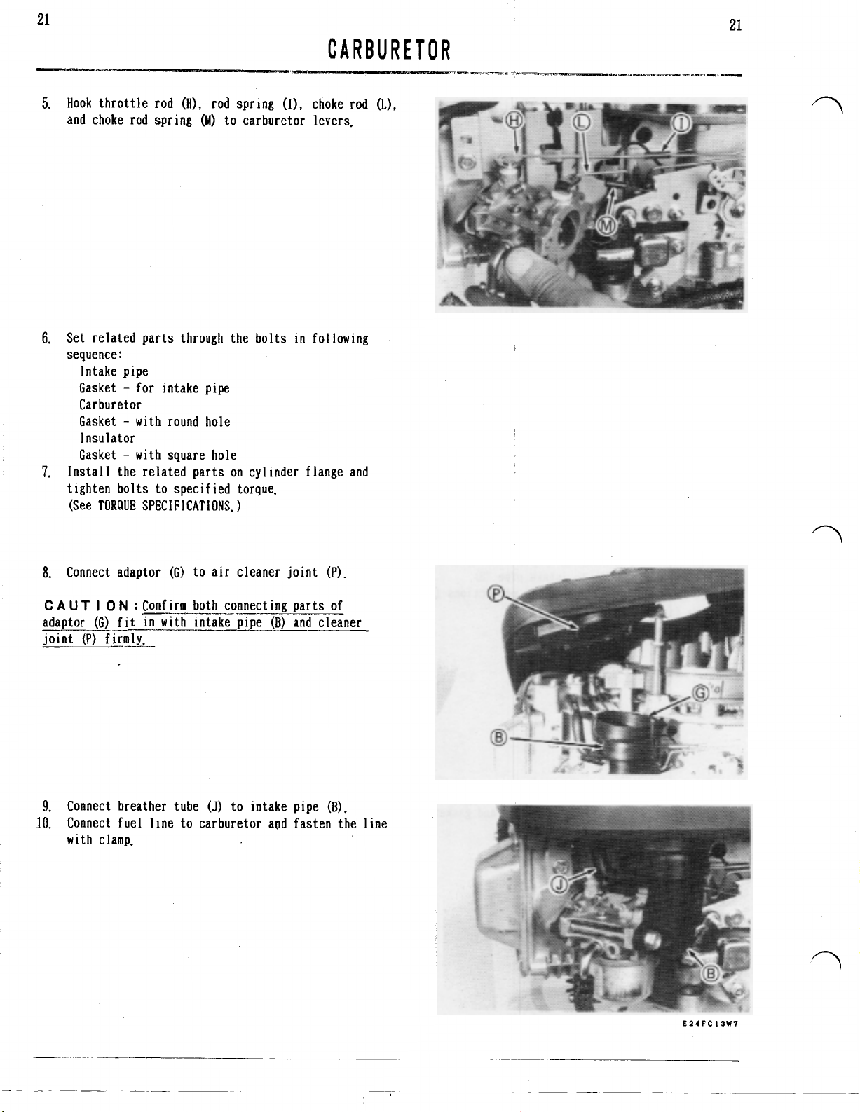
1.
Install adaptor (G) to intake pipe
2.
Fit holes
(W)
in gasket
(X)
on projections
pipe flange.
3.
Put collars
4.
Arrange gasket
(Y)
in place.
(A).
insulator
shown.
Gasket
Gasket
(A)
:
Cylinder side
(E):
Carburetor side
(B).
(F),
and gasket
(V)
of intake
(E)
as
Page 28
21
21
CARBURETOR
Hook throttle rod
5.
and choke rod spring
6.
Set related parts through the bolts
sequence
7.
Install the related parts on cylinder flange and
tighten bolts to specified torque.
(See TORQUE SPECIFICATIONS.)
:
Intake pipe
Gasket for intake pipe
Carburetor
Gasket with round hole
Insulator
Gasket with square hole
(HI,
rod spring
(M)
to carburetor
(I).
choke rod
levers.
in
following
(L),
8.
Connect adaptor (G) to air cleaner joint (P).
C A UT
adaptor
joint (P) firmly.
9.
10.
I 0 N
:
Confirm both connecting parts of
(G)
fit in with intake pipe
Connect breather tube
Connect fuel line to carburetor and fasten the line
with clamp.
(J)
(B)
and cleaner
to intake pipe
(B).
Page 29

22
22
CARBURETOR
315510 6100C 5510C
15001 2541 12541
EZIPAOTWI
Page 30

23
23
COOL
W
A R N
I
N
G
:
Gasoline
Avoid fires due to smoking
Engine cover
fuel valve, and fuel tank cover,
1.
Shut fuel valve
carburetor inlet.
2.
Open fuel valve and drain fuel into suitable container,
3.
Remove recoil starter.
CAUT I ON:
4.
Remove oil filler cap
5.
Disconnect fuel line
is
removed together with fuel tank, tank cap,
(A)
and disconnect fuel line
Do not lose washers
is
extremely flammable.
or
careless practices,
(C)
(E).
(F)
from fuel valve (A).
and collars (D).
I
NG
(B)
from
SYSTEM
W A R
N I N G :
avold engine starting.
6.
Loosen flywheel nut (G) by turning
Use air impact wrench to avoid flywheel retation.
7.
Remove flywheel nut (G). washer
(I).
8.
Slightly lifting up engine cover, disconnect intake
pipe adoptor
9.
Remove engine cover assy.
10.
Remove oil filler
Remove plug cap from spark plug to
it
counterclockwise.
(H),
and starting pulley
(J)
from air cleaner outlet
(1).
(K).
E26FCOZW4
Page 31
24
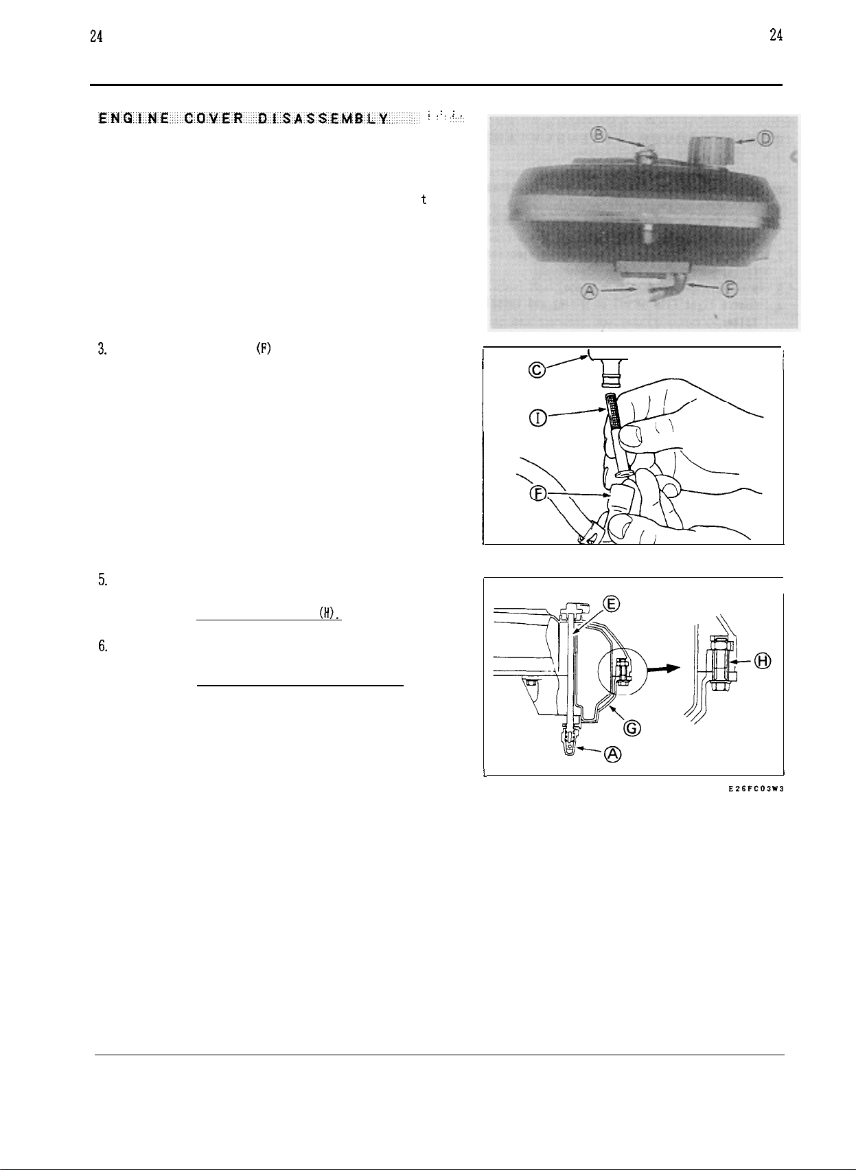
1. Remove fuel tank cap (D).
2. Pull fuel valve knob (B)
COOLING SYSTEM
off from valve shaft (E)
: : :
: : : : :
.::,
24
N 0 T E : Knob (B) is install
ed on valve shaft (E) w i
fit.
3.
Disconnect fuel line
(F)
fiom fuel tank (C).
4. Remove fuel strainer (I) from fuel tank (C).
5.
Remove fuel tank cover (G).
t
h snap
l
J
I
/;;\A---
w
I
1
C AUT I ON : Do not lose collars
6.
Remove fuel valve (A).
C
A UT
I 0 N : Do not disassemble fuel valve (A).
(If).
t
E2SFC03W3
,
Page 32

COOLING SYSTEM
Assembly and installation are reverse of disassembly and
removal.
1.
2.
3.
4.
5.
6.
7.
Note following points.
Apply locking agent on thread
when
replace stud for
engine cover mounting.
Align notch (A) of oil filler with projection
(B)
filler port.
Make sure O-ring (C) is in place.
Coat a light film of oil on O-ring and install oil
filler.
Tighten screws in crisscross sequence and evenly
specified torque.
Do not tighten screw completely at a time.
Holding pulley, torque flywheel
nut
as specified
TORQUE SPECIFICATIONS.
Connect air cleaner outlet
(0)
and intake pipe adaptor
(E) firmly.
of
to
in
25
:‘:’
:::::
.::::
,jjjj
: :
EZSFCO4W2
Page 33

26 26
RECO
C
A
UT
I 0 N
:
Do
not wedge rope between reel and case.
1.
Pull
handle
Then hold rope in place with locking pliers or knot
2.
Pull
knot in handle
W
A R N I N
avoid injury.
3.
While carefully holding reel
locking pliers or untie knot.
4.
Unwind spring tension slowly.
NOT
E
:
1
through 4 are not necessary except when rope and/or
handle are changed. Instead of the steps, unwind spring
tension keeping rope in notch
out
about
250
mm
(10
in).
(B)
out and untie
G
:
Wear gloves during disassembling to
(C)
and case
As
for recoil starter with extended rope, steps
(E)
of reel.
I L STARTER
(A).
it.
(D),
remove
5.
Remove screw
6.
Remove retainer
7.
Before removing pawl
pawl, then remove pawl and spring
i
(F)
and washer
(H)
with circlip
(J),
(G).
(I)
carefully.
make sure position of the
(K).
Page 34

27
27
W
A R N I
RECO
N
G
:
When removing reel (C), be careful
I L 'STARTER
that recoil spring under the reel does not fly loose
and causes injury. The spring
NOT
E
:
There should be no spring tension on reel when
removing reel. If tension
is
under great pressure.
is
felt, push reel back into
place and gently "wiggle" it until reel can be easily
removed.
8.
Rotate reel
(C)
one-quarter turn clockwise from rest
position where no tension can be felt. Then, slowly
lift reel straight up out of case.
W A R
N I N
G
:
Be careful that recoil spring
(M)
does not fly loose from reel (C) and causes injury.
The
9.
If
is
under great pressure:
recoil spring
(M)
must be removed from reel (C), hold
the reel with spring side downward in suitable container
and tap reel to remove recoil spring.
1.
Dip
metal parts in bath of high flash-point solvent, if
necessary.
C
A
UT
I
0
N
:
Do not clean any non-metalic parts
in
solvent. They may be damaged by the solvent.
2.
Check starter pawl for chips
3.
Check starter rope for excessive wear
4.
Check springs for break, rust, distortion,
i
t
ion.
cond
If
damage
WAR
is
found, replace the part.
N 1 N
G
:
Do not throw away recoil spring as
or
excessive wear.
or
fraying.
or
weakened
installed in reel. Recoil spring may fly loose from
reel and cause injury.
E27FAO2W2
Page 35

28
28
RECO
W
A R N I
!
installation to avoid injury. The recoil spring must
be assembled with great pressure.
1.
Coat grease for high temperature application on recoil
spring
2.
Set recoil spring
(C)
catches
3.
Wind recoil spring
4.
Make sure that gap between spring hook
of reel boss
If not, make the gap by bending spring end with long
nose pl ier.
N
G':
Wear gloves during recoil spring
_._-
(A)
and sliding surfaces.
(A)
in reel
hook
(D)
in
reel.
(A)
into reel
(F)
is
2 4 mm
(B)
so
(B)
(0.08
that spring end
counterclockwise.
0.16
I
L
(E)
and outside
in.).
STARTER
(M)
If rope
5.
3.5
(G)
is
unwound from reel
turns
counterclockwise facing pawl groove
(B),
wind rope
in
(H).
reel
Page 36

29
29
RECO
7.
Install spring
groove.
8.
Install retainer
NOT
E
:
Apply locking agent on screw
C
A U T I 0
tightening may disturb movement
9.
Tighten screw
SPECIFICATIONS.)
N
(J)
and pawl
(M),
(K)
into the respective
covering pawl with
"R*
(N).
:
Do
not over tighten screw
of
pawl.
(N)
to specified torque. (See TORQUE
(N).
Over
I
L
STARTER
side groove.
11.
Pull
rope out of case and install handle.
12.
Check movement
13.
Pull
rope out to the end.
out to the end
preloading
clockwise, keeping rope
then check the condition again.
of
pawl, pulling and returning rope.
If
rope can not be pulled
or
can not be rewound when released,
is
too much. Rotate reel
(G)
in
notch
(B)
1
turn
(0)
of reel, and
Page 37

30
30
ELECTRIC
1.
Disconnect spark plug cap, and ground the cap
terminal. test. Do not touch any rotating parts
2.
Turn key switch to "ON" position and check
condition.
(STARTER DOES NOT ROTATE)
I--
Does pinion rotate?
""-I
(STARTER
ROTATES
BUT
SLOW)
STARTER
I--
@Weak or faulty battery.
@Faulty leads or connection.
*Faulty key switch.
0
Faulty starter motor.
k
W
and equipment during test.
C
A
UT
"OFF", disconnect negative lead from battery as
soon as possible.
CHARGl
A R N I N G :
NG
Engine may be cranked in this
-_-
I
0 N :
If
starter does not stop by key switch
Charge
Repair or replace
Repair or replace
Repair or replace
or
replace
of
engine
and well charged?
(STARTER ROTATES
(STARTER DOES NOT STOP
BUT
CAN
IN
NOT
CRANK
NO
KEY
SWITCH "OFF")
NO
ENGINE)
harge or replace
@Faulty leads or connection.
0
Faulty starter motor.
0
Faulty engine.
*Worn pinion or ring gear.
0
Incorrect starter alignment. Correct
0
Faulty key switch.
+Repair or replace
Repair or replace
Repair or replace
Repair or replace
Repair or replace
Correct
Repair or replace
Page 38

31
31
ELECTRIC STARTER
WA
R N I
N
G
:
Disconnect negative
(+)
then positive
1.
Disconnect battery before removing electric starter from
lead to prevent spark at terminal.'-'
(-)
lead first and
&
CHARGl NG
engine to avoid accidental running of starter in handl-
i
ng.
2.
Remove electric starter from engine.
W A
R N I
N
G
:
The test room must be free from any
flammable object. Keep away your body from pinion.
CA
UT
I
O
N
:
Be careful not to deform electric starter
I-
body by holding.
Hold electric starter with vice.
Connect cable
Connect jumper cable
(A)
with positive
(B)
with negative
(+)
battery terminal.
(-)
battery
terminal.
Touch starter body with the other end of jumper cable
(B)
intermittently (within one second).
or
If pinion does not turn, repair
replace starter motor.
E28FC22W2
1
C
A
U
T
I
0
N
:
Because of difficulty
further disassembling
is
not
recommended.
in
reassembling,
8
5
E28FC23W2
Page 39
32
32
ELECTRIC STARTER
1.
Coat multi purpose grease on reduction gears.
2.
Do
not miss putting
shim
on shaft
in
cover assy.
&
CHARGl NG
E28FC15WI
1.
Disconnect connector
2.
Start and warm up engine.
3.
Set multimeter selector switch to
4.
Connect tester positive prove with stator term
and negative prove with crankcase.
5.
Run
engine at
If voltage
3,000
is
less than
(A).
2!jV
DC
rpm and check voltage.
8V,
replace stator.
ion.
posit
inal
(B)
E28FC24WI
E28FC25WI
Page 40

I
GN
I T I
ON
SYSTEM
33
Transistor controlled ignition system
engines and this system consists of following components.
1.
Ignition coil
2.
Control
3.
Flywheel (with permanent magnet)
These components do not mechanically contact and periodic
maintenance
I,:
CU: Control unit
R,
R2:
unit
is
not required.
Primary coil
Secondary coil
:
Control resistor
Control resistor
is
used for these
TR,
:
Transistor
TR2:
Transistor
F
:
Flywheel
SP
:
Spark plug
SW
:
Engine switch
To check ignition system, check spark as follows;
1.
Remove spark plug and connect plug cap with the removed
spark plug.
2.
Install spare plug
from hole.
W
A R N I N G :
cap, but not spark plug.
3.
Keeping contact with spark plug metal part (not center
electrode) and engine block, crank engine.
C
A
UT
I
0
N
:
Do
cleaner.
e
If
no
or
very weak spark
and regap
try engine cranking again.
If spark
with new spark plug.
it
is
not improved by cleaning, try checking again
to
plug hole to avoid fuel spitting
To
avoid electric shock, hold plug
not clean spark plug with bead
is
observed, clean spark plug
to
0.7
0.8
mm
(0.028
0.031
or
in.
sand
and
E30FCOIW2
If
spark
is
not improved yet, check ignition system.
E30FCOBW2
Page 41

34
I
GN
1.
Set multimeter selector switch to
2.
Check resistance between terminal
R
x
(A)
and case
IT
I
ON
SYSTEM
position.
(B).
34
If resistance
unit.
C A U T I 0 N
I
.CONTROL UN IT RES I STANCE
Case
N 0 T
E
:
This check may not cover every defect.
is
out of specified value, replace control
:
Do
not use Megger.
Terminal
(B)
(A)
Case
(B)
E30FCOSW2
r
1.
Check resistance between the points as specified.
2.
If resistance
ignition coil.
IGNITION COIL RESISTANCE
Primary
coil
Secondary
1
coi
is
out
of
specified value, replace
Connect ion
Primary terminal
and Core (C)
Plug lead
and Core (C)
(A)
(B)
Resistance
0.67
(R
x
6.0
(R
x
Range)
Range)
EBOFC
I
OW2
Page 42

35
35
IGNITION
1.
Remove starting pulley and engine cover assy. (See
GINE COVER REMOVAL.
2.
Avoiding flow-out of engine oil, place engine on bench
so
that flywheel faces sideward.
3.
Put soft metal piece on shaft end to avoid demage and
strike metal piece sharply until flywheel comes loose.
1.
Before installing flywheel, remove grease and oil from
taper part of crankshaft and taper hole of flywheel.
2.
Make sure key
3.
Torque
nut
as specified
(See ENGINE COVER ASSEMBLY AND INSTALLATION.
)
is
in
place when installing flywheel.
in
TORQUE SPECIFICATIONS.
SYSTEM
EN-
ESOFCIIWI
If ignition coil
installing coil.
1.
Insert
(A) between coil legs (B) and flywheel ‘rim
2.
Pushing coil to flywheel, tighten coil mounting screws
firmly.
Intermediate connector installation
Be careful of terminal direction.
A:
Nut
B:
Control
C: Stop switch terminal
D:
Nut
E: Washer
0.3
is
removed or replaced, adjust AIR-GAP in
mm
(0.012
in.)
feeler gauge or solid sheet
(c).
is
as shown.
F:
Insulator
unit
terminal G: Control plate
H:
Insulator
I:
Bolt
E30FCIZWI
E30FC I3Wl
Page 43

36
I
GN
I T I
ON
SYSTEM
36
Engine switch linked with throttle lever
trol pannel of engine and operated as follows:
1.
When control lever
idle, or choke, control lever
(B).
tang
2.
When control lever
tion, the lever contacts with engine switch tang
grounds ignition circuit.
C
AUT
I
0
N
:
Check and clean engine switch tang area to
keep good contact.
3.
Engine switch installation
Control lever
Switch tang
Nut
Washer
Control plate
Insulator
G:
Insulator
H:
Bolt
(A)
(A)
is
positioned at slow idle, fast
is
is
pulled beyond slow idle posi-
is
as shown,
is
equipped on con-
far from engine switch
(B)
and
ESOFC
l5W2
is
Engine switch linked with band brake
case side and operated as follows:
1.
When brake control lever on equipment
position, control cable
(B)
shoe
tang
2.
When brake control lever on equipment
position, control cable
shoe
tang
C
A
UT
keep good contact.
NOT
throttle-lever-linked engine switch.
from flywheel and to release engine switch
(F)
from lever
(B)
to contact flywheel and to make engine switch
(F)
contact with lever
I 0 N
:
Check and clean engine switch tang area to
E
:Switch configulation
(A).
(D)
pulls lever
(D)
releases lever
(A).
is
equipped on crank-
is
moved to start
(A)
to release
is
moved to stop
(A)
to force
the same as that of
E30FC16W2
Page 44
31
CYL
I
NDER HEAD
1.
Remove spark plug and set compression gauge to plug hole.
2.
Crank engine with recoil or electric starter several
times and check highest reading.
is
less
than
343
kPa
(50
If highest reading
in
check engine
NOT
E
:
Battery should be fully charged for this test.
1.
Disconnect plug cap from spark plug.
2.
Remove rocker cover.
3.
Remove cyl. head.
4.
If push rods are removed, mark push rods
placed in their original positions in re-installing.
accordance with TROUBLE SHOOTING.
psi),
so
they are
37
E32FCOSWI
W
A
R
N
I N
G
:
If chemical cleaner
follow the manufacturer's safety instructions carefully.
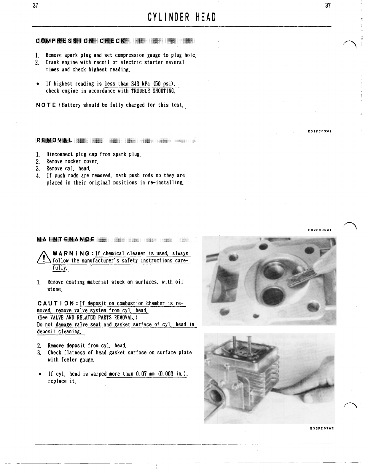
1.
Remove coating material stuck
stone.
C
A
UT
I
0
N
:
If deposit on combustion chamber
moved, remove valve system from cyl, head.
(See
VALVE
AND
RELATED
Do not damage valve seat and gasket surface of cyl. head in
deposit cleaning.
Remove deposit from cyl. head.
2.
Check flatness of head gasket surfase on surface plate
3.
with feeler gauge.
If cyl. head
replace it.
PARTS
is
warped more than
on
REMOVAL.)
is
used, always
surfaces, with oil
is
re-
0.07
mm
(0.003
in.),
E32FC06WI
Page 45
38
CVL
I
NDER
C
AUT
I
0 N :
Gasket
Do
not damage surface of gasket during installation.
If surface coating
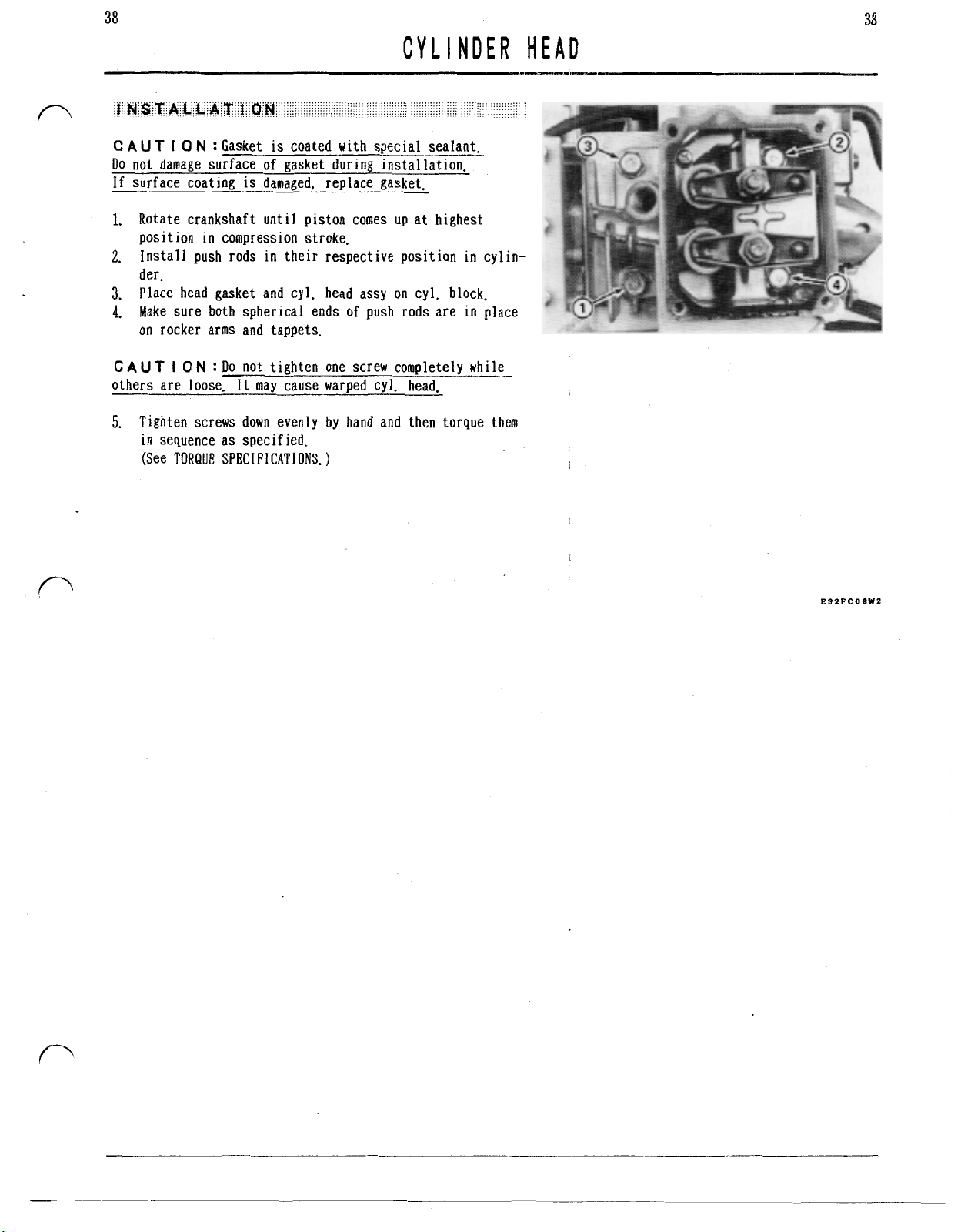
1.
Rotate crankshaft until piston comes up at highest
position in compression stroke.
2.
Install push rods in their respective position
der.
3.
Place head gasket and cyl. head assy on cyl. block.
4.
Make sure both spherical ends of push rods are
on rocker arms and tappets.
is
coated with special sealant.
is
damaged, replace gasket.
in
in
HEAD
cylin-
place
38
CAUT I
others are loose.
5.
0
N
:
Do
not tighten one screw completely while
It
may cause warped cy]. head.
Tighten screws down evenly by hand and then torque them
in
sequence as specified.
(See TORQUE SPECIFICATIONS.
E32FCOSW2
Page 46
39
39
VALVE
When any part related to valve clearance
ified for defect correction,
or
after engine has been used
is
changed or mod-
for long period, adjust valve clearance.
NOT
E
:
Do
adjustment while engine
1.
Turn
crankshaft
in
tion
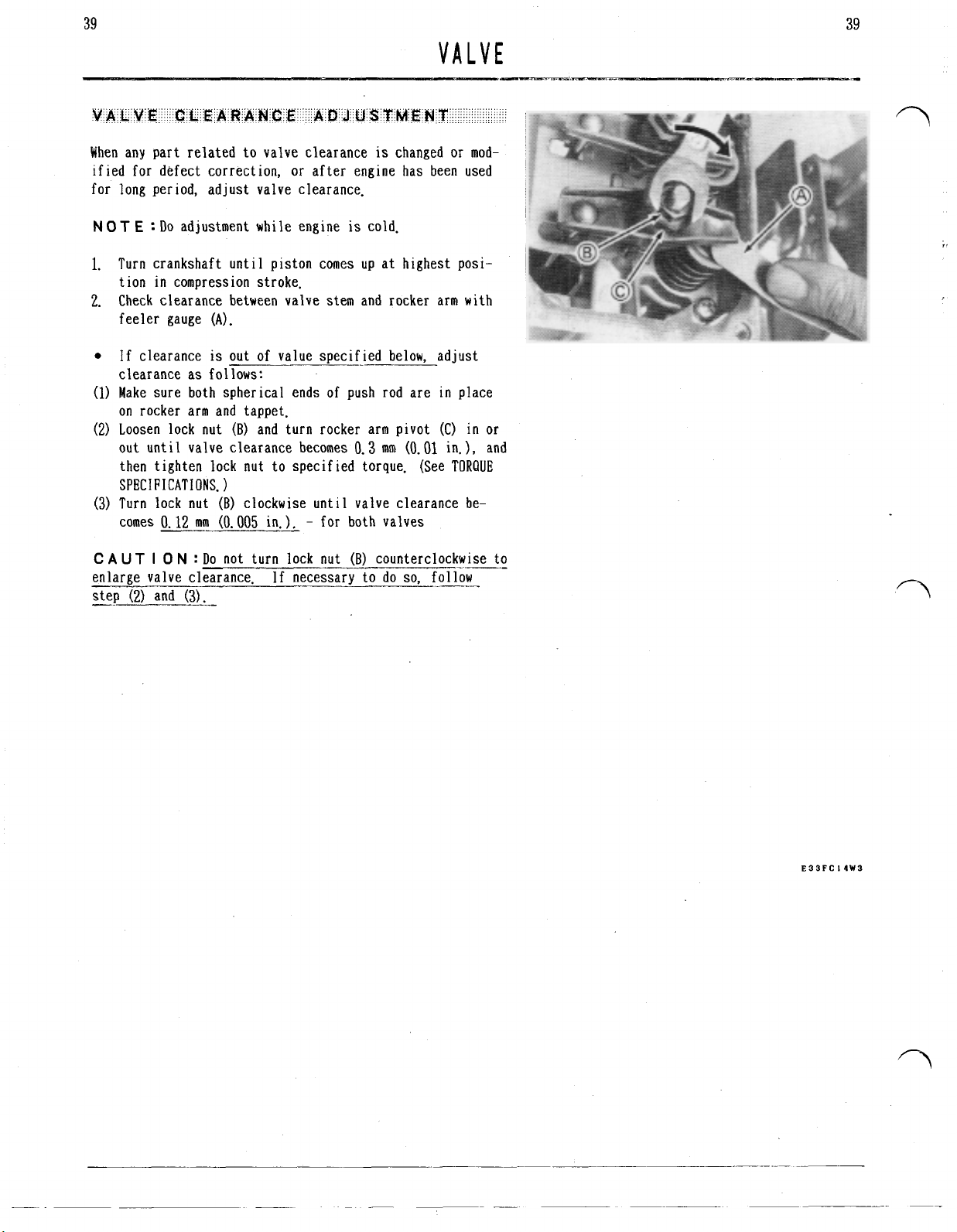
2.
Check clearance between valve stem and rocker arm with
compression stroke.
feeler gauge
If clearance
until
(A).
is
out
piston comes
of
value specified below, adjust
is
cold.
up
at highest posi-
clearance as follows:
(1)
Make sure both spherical ends of
push
rod are
in
place
on rocker arm and tappet.
(2)
Loosen lock nut
out until valve clearance becomes
then tighten lock
(B)
and turn rocker arm pivot (C)
0.3
mm
(0.01
nut
to specified torque. (See TORQUE
in
or
in.), and
SPECIFICATIONS.
(3)
Turn lock
comes
C
A
UT
enlarge valve clearance If necessary to do
0.12
I
0
nut
(B)
clockwise
mm
N
:
Do
(0.005
in.). for both valves
not turn lock nut
until
valve clearance be-
(B)
counterclockwise to
so.
follow
E33FC
I4W3
Page 47
40
VALVE
is
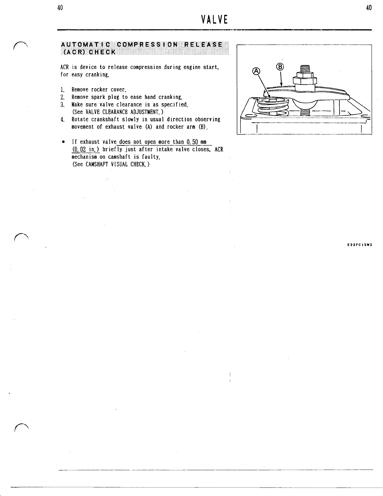
ACR
for
1.
2.
3.
4.
device to release compression during engine start,
easy cranking.
Remove rocker cover.
Remove spark plug to ease hand cranking.
Make sure valve clearance
(See VALVE CLEARANCE ADJUSTMENT.
Rotate crankshaft slowly in usual direction observing
movement of exhaust valve
is
as specified.
(A)
and rocker arm
(B).
40
If exhaust valve does not open more than
(0.02
in.)
briefly
mechanism on camshaft
(See CAMSHAFT VISUAL CHECK.
just
after intake valve closes.
is
faulty.
0.50
mm
ACR
E33FC15WZ
Page 48

41
NOT
E
:
Mark push rods
original positions in re-installing.
1.
Remove push rods.
2.
Unscrew lock nuts
rocker arms (C).
3.
Place screw head of valve spring compressor
valve head and
and retainer
4.
Compress spring and remove retainer
pliers.
5.
Remove compressor and valve spring.
(F).
so
they are placed in their
(A)
and pivots
SI
ip jaw of compressor between spring
(B),
and then remove
(F)
with needle nose
VALVE
(D)
on the
(E)
41
NOT
E
:
Before pulling valve out of guide
burrs
from valve stem, and oil to stem to avoid damaging
valve guide.
When re-installing
ing agent on thread and tighten to specified torque. (See
TORQUE
SPECIFICATIONS.
or
replacing rocker arm stud, apply lock-
)
(G),
remove all
E33FC16W3
Page 49

42
1.
Check valve head for excessive deposit and gas leakage.
2.
Remove carbon from valve head with wi-re brush.
3.
Check valve head for warped face
margine
If valve head has above defect, replace valve,
N
0
T
and deposit triggers gas leakage causing valve defects.
Therefore unleaded gasoline
4.
Check valve stem for sticking, gummy deposit, discoloration at area covered by valve guide, and excessive
corrosion.
5.
Remove carbon from valve stem as well as head.
If valve stem
smoothly in guide, replace valve.
(B)
of less than
E
:
Excessive deposit
is
worn excessively or does not move
0.5
is
is
(A)
dent on face and
mm
(0.020
caused by leaded gasoline,
recommended.
in.).
42
N 0 T
E
:
Sticking and discolorat ion are caused by over
heating of engine, or gas leakage from valve face. Therefore
such causes must be corrected as well as valve maintenance.
Gummy deposit
system and use fresh gasoline. Remove gasoline from fuel
system before long storage.
6.
Check valve stem for worn stem end.
7.
Grind worn stem end (C,D) squarely to stem shaft with
valve lapping guide
If length from stem end to groove
(0.15
is
caused by old or stale gasoline. Clean fuel
(E)
and oil stone
in.) after grinding, replace valve.
(F).
is
less than
3.8
mm
I
\
E33FC
I7W4
Page 50

43
1.
Check diameter
guide at several points with micrometer.
If
diameter
of
valve stem in area covered
is
less than
MIN.
replace valve.
VALVE
by
valve
43
VALVE STEM DIA.
2.
Check bend of valve stem at center part with
(A)
and dial indicator
If bend (dial gauge reading) of valve stem
0.03
mm
C
AUT
face.
(0.0012
I
0
N
If
valve face
in.
:
Do
not try to grind or recondition valve
is
worn or damaged, replace
MIN
(B).
replace valve.
V
blocks
is
more than
it.
E33FC
I8W2
1.
Check valve spring for any damage and replace it if
necessary.
2.
Check free length of valve spring with vernier calipers.
If length
spring.
is
less than
for
both springs
31.5
mm
(1.240
in.), replace
E33FC
I9WI
Page 51

44
VALVE
If valve does not contact all way around with seat, lap
valve into seat.
1.
Coat fine lapping compound sparingly on valve face.
2.
Rotate valve in circular motion with valve lapper (A).
N 0 T
E
:
Lapping mark should appear on or near center of
va
1
ve face.
3.
Check valve every
until uniform ring appears on valve seat all way around.
4.
After lapping, wash parts
Dry parts thoroughly.
8
to
10
strokes and continue lapping
in
solvent to remove compound.
44
Reface valve seat with
1.
enough material to make smooth and concentric seat.
Use
30°
2.
(0.021
A
Make a
3.
at edge of seat.
Coat marker and check contact of valve face and seat.
4.
Contact should be at center part of valve face as shown
and all way around.
Lap valve into seat. (See LAPPING.)
5.
cutter to narrow seat width to
0.046
in.
:
Seat width
light
pass with
1.
45’
cutter, removing only
0.53
45’
cutter to remove any burr
1.16
E33FC2OW2
mm
E33FC2lW2
Page 52

45
1.
Use valve guide cleaner to clean
2.
Check inside diameter of valve gu
i
nside of valve guides.
11
de at several points
with inside micrometer.
45
VALVE
If diameter
VALVE
Intake
Exhaust
is
more than
GUIDE
MAX,
rep
ace cyl. head.
INSIDE
5.550
5.560
mm
mm
D
(0.2185
(0.2189
I
A.
MAX
in.
in.
E33FC22W2
(A
with push rod),
(B
th valve stem), and (C
wi
with pivot).
If necessary, replace rocker
1.
Check bend of push rod at center part with
(A)
and dial indicator
If bend (dial gauge reading)
(0.024
in.),
replace push rod.
(B).
arm.
is
more than
V
blocks
0.6
mm
E33FC23WI
E33FC24WI
Page 53

46
CRANKCASE COVER
W
A R N
I
N
G
:
Be careful not to burn yourself by
oil.
1.
Drain engine
2.
Remove rust and burr from edge
3.
Loosen screws, and tap parts near dowel alternately with
soft mallet.
1.
Check inside diameter
points with inside micrometer.
oil
to suitable container.
of
PTO
of
PTO
bearing
shaft step.
(A)
at several
46
E34PCOIWI
If diameter
is
more than
25.100
mm
(0.9882
place crankcase cover.
2.
Check inside di-ameter
of
camshaft bearing
several points with inside micrometer.
If
diameter
is
more than
14.070
mm
(0.5539
place crankcase cover.
.in.), re-
(B)
at
in.), re-
E34FCO6W2
Page 54

47
47
CRANKCASE
0
1
':L
SEAL
If
oil leakage through oil seal
damaged, replace oil seal.
1.
Remove oil seal by tapping
punch.
2.
Placing spring held seal lip
into
housing
with
housing end (C).
3.
Before final assembly, pack some amount of grease for
high
temperature application into space between seal
(A:)
and dust 1 ip
REPLACEMENT
is
observed or seal lip
it
out with screw driver or
(A)
inside, push oil seal
until
seal outside surface becomes flush
(B).
COVER
is
1
ip
Clean gasket surface and place new gasket on crankcase.
1.
Pack grease into oil seal. (See
2.
Coat a light film
3.
Make sure governor weights are closed.
4.
Make sure governor gear
5.
with
cam gear when installing crankcase cover.
of
oil on bearings.
is
OIL
SEAL
REPLACEMENT.)
properly aligned to mesh
Do
not
force cover into position.
Install crankcase cover and tighten bolts down evenly
6.
by hand. Tighten bolts
in
the sequence as shown and
to
the specified torque. (See TORQUE SPECIFICATIONS.)
Do
not tighten one bolt completely before the others.
It
may cause warped crankcase cover.
is
When new crankcase cover
7.
drain plug
(A)
must be performed carefully. (See NOTE
used, tightening of side
in TORQUE SPECIFICATIONS.)
E34FC04W2
E34FCO7W2
Page 55
48
CAMSHAFT
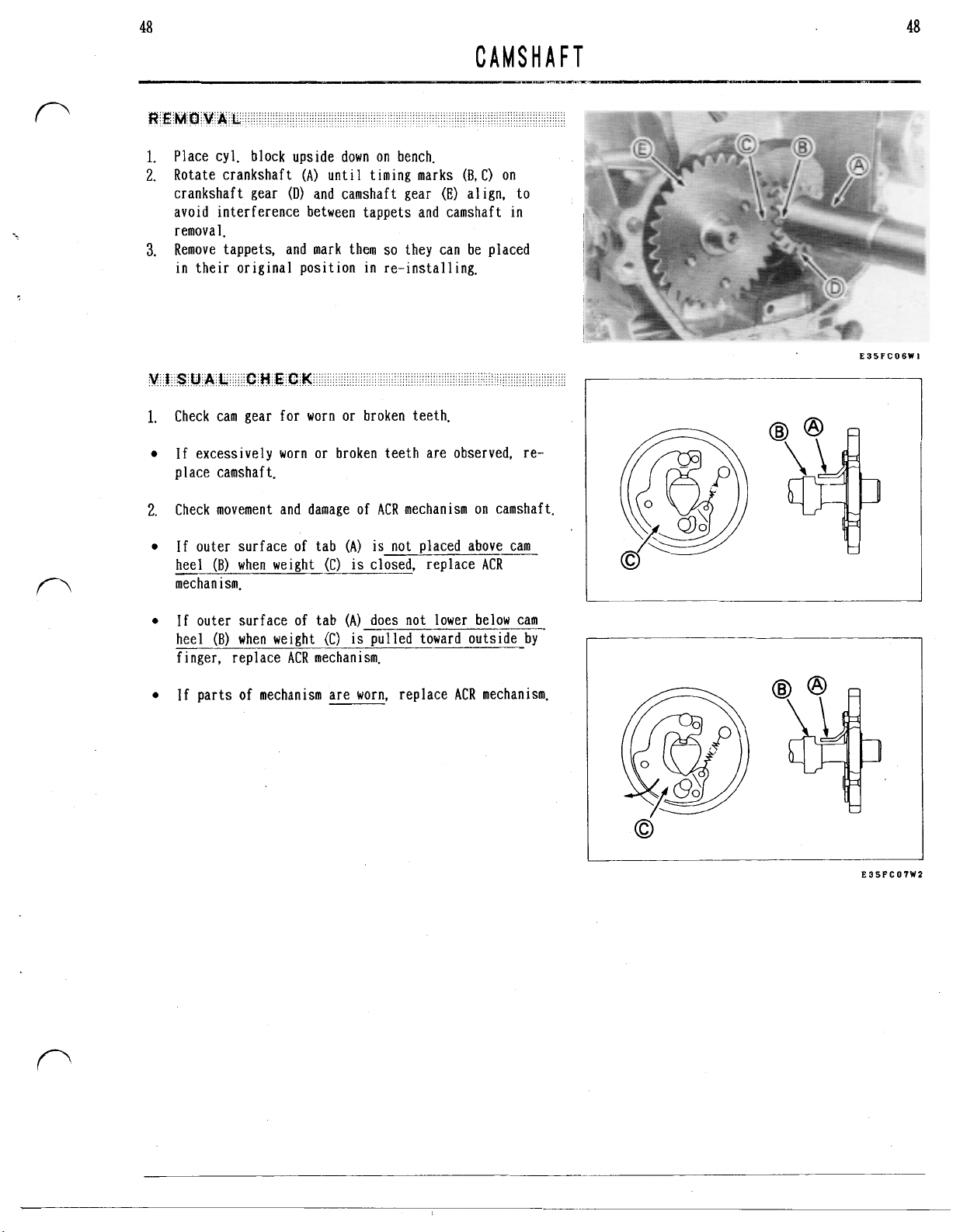
1.
Place cyl. block upside down on bench.
2.
Rotate crankshaft
crankshaft gear
avoid interference between tappets and camshaft
removal.
3.
Remove tappets, and mark them
in
their original position
Check cam gear for worn or broken teeth.
If excessively worn or broken teeth are observed, re-
place camshaft.
(A)
until timing marks
(D)
and camshaft gear
so
they can be placed
in
re-installing.
(B,
C) on
(E)
align, to
in
48
E35FC06WI
Check movement and damage of ACR mechanism on camshaft.
(A)
is
If outer surface of tab
heel
(B)
when weight (C)
mechanism.
If
outer surface of tab
(B)
heel
finger, replace ACR mechanism.
If parts of mechanism are worn, replace ACR mechanism.
when weight (C)
not placed above cam
is
closed, replace ACR
(A)
does not lower below cam
is
pulled toward outside by
E35PCO'IWZ
Page 56

49
CAMSHAFT
2.
Check cam lobe height with vernier calipers,
49
If lobe height
replace camshaft.
1.
Place cyl. block upside down
2.
Install tappets in their respective positions and push
them all the way into guide to avoid interference with
camshaft in assembling.
3.
Rotate crankshaft
4.
Aligning timing marks
into crankcase.
is
less
until
than
22.80
on
piston
(A)
and
mm
(0.898
bench.
is
at highest position.
(B),
install camshaft
in.).
E35FC08W2
E35FCOSWI
Page 57

50
PI
STON
C
A
UT
I 0
N
:
Remove any carbon or ridge at top of cyl.
bore to avoid piston ring breakage in. removing.
4t
CON-ROD
50
Rotate crankshaft
1.
Loosen con-rod bolts and remove con-rod cap.
2.
Push piston and con-rod out through top of cylinder.
3.
Remove piston from con-rod.
4.
Remove piston rings from piston with ring expander
5.
(A)
to expose con-rod bolts
(B).
(C).
E36FCIZW2
Page 58

51
PI
STON
Appearance of piston and piston rings shows condition of
engine
piston and/or piston rings and remove cause of such
damage.
in
running. If excessive damage
is
observed, replace
&
51
CON-ROD
Rings of wrong size
1.
will
I
2.
e
3.
e
4.
e
not fit
consumption and excessive blowby.
Check ring end gap and arrange end gap as shown in
PISTON RING INSTALLATION.
Scuffing
when friction and/or combustion temperature are unusually high.
Check and clean cooling system.
Check and correct quality and level of oil.
Check and adjust fuel and combustion systems.
Engine running at abnormally high temperature may cause
varnish, lacquer,
grooves making rings stick.
Apply same treatment as above
Vertical scratches across piston rings are due to
abrasive
been left in engine during overhaul, or may be loose
lead and carbon deposit.
Check air cleaner and clean
Check any air intake through abnormal route.
Clean engine inside and change oil.
to
or
scoring of both rings and piston occurs
in
engine. Abrasive may be airborne, may have
or
rings having improper end gap
shape of cylinder.
or
carbon deposit formed
This
causes high oil
2.
or
replace damaged one.
in
piston ring
(A)
Scratches across oil side rails
5.
in
engine oil, and other rings will also be worn
this
condition causing high oil consumption, increased
in
deposit
e
Clean engine inside and change oil.
combustion chamber, and ring sticking.
are due to abrasive
in
Page 59

52
PI
STON
C
A
UT
I 0 N
:
Do
not use caustic cleaning solution
brush to clean piston.
1.
Remove all deposits from piston.
2.
Clean carbon from piston ring grooves with ring groove
is
cleaner. If cleaning tool
ton ring breaking into suitable size.
3.
Make sure oil return passages in ring groove are open.
not available. use old pis-
&
CON-ROD
or
wire
52
1.
Check clearance between ring groove and ring using
new ring and feeler gauge.
If clearance
piston. for top and second rings
2.
Check inside diameter of piston pin hole at several
points with inside micrometer.
If diameter
replace piston.
is
more than
is
more than
0.10
15.050
mm
(0.004
mm
(0.5925
in.), replace
in.),.
E36FC 13W
I
E36FC
E36FC
I4W2
I
SW
I
Page 60
53
PI
STON & CON-ROD
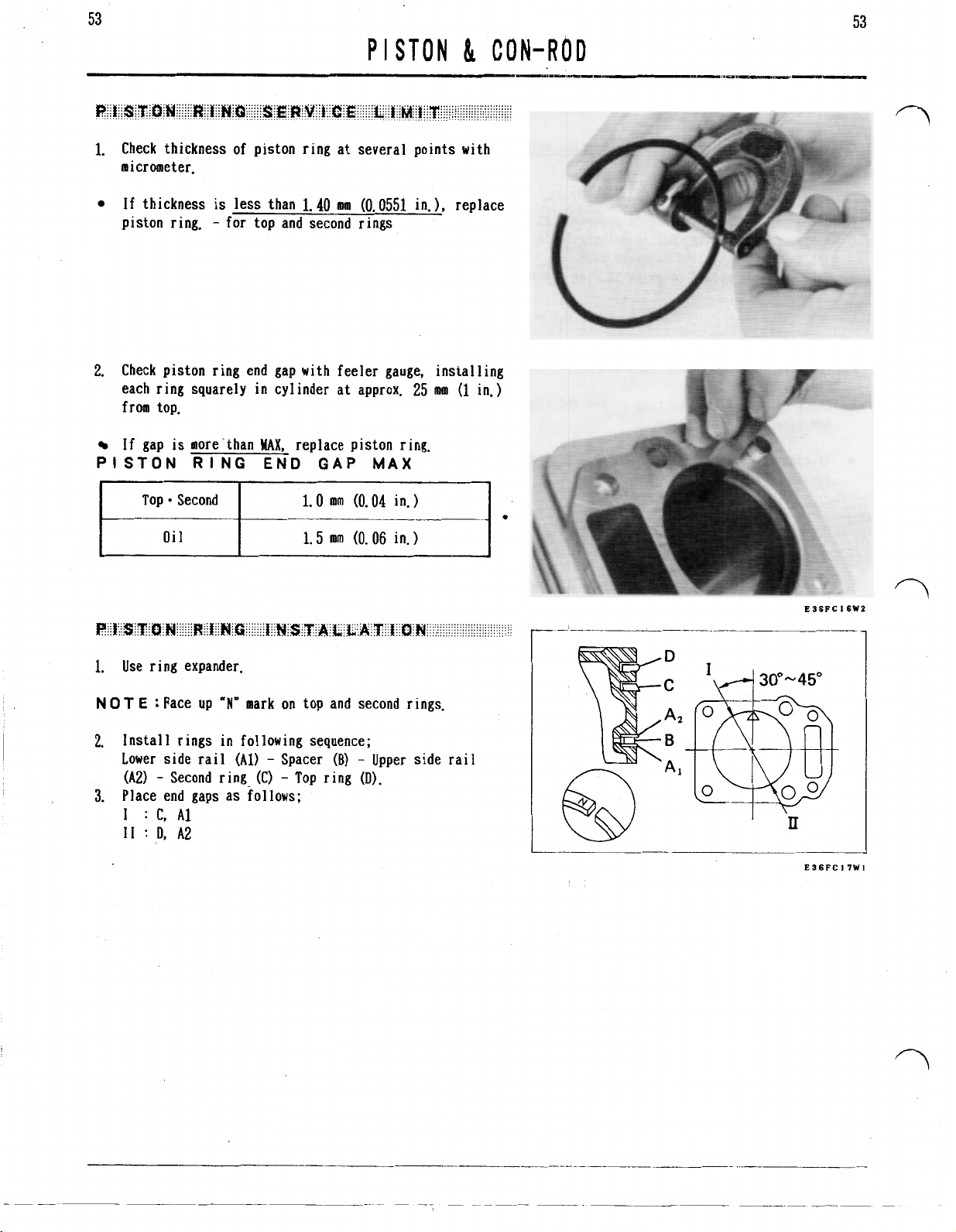
1.
Check thickness of piston ring at several points with
micrometer.
If
thickness
piston ring. for top and second rings
2.
Check piston ring end gap with feeler gauge, insta
each ring squarely in cylinder at approx.
from top.
is
less than
1.40
am
(0.0551
in.), replace
.11
ing
25
mm
(1
in.)
53
If gap
PISTON
1.
Use ring expander.
N 0 T
2.
lnstall rings in following sequence;
Lower side rail
(A21
Place end gaps as follows
3.
1
11
is
more-than
RING
Top Second
E
:
Face up
Second ring (C)
:
C.
A1
:
D,
A2
MAX,
replace piston ring.
END
“N”
mark on top and second rings.
(Al)
GAP
1.0
mm
1.5
mm
Spacer
(B)
Top ring
MAX
(0.04
(0.06
Upper side rail
(D).
.
in.
in.
E36PC
I6W2
E36FCl7WI
Page 61

54
PI
STON
Check con-rod especially big end for wearing, scratching,
scoring, and/or discoloring.
Abnormal wearing and scratching are caused by foreign
particle(s) in oil.
Clean engine inside and change oil.
Check air cleaner. and clean
If con-rod and/or crankshaft are used again, remove
ridges on their surface carefully.
or
replace damaged one.
&
CON-ROD
54
Scoring and discoloring are symptom of
and/or over heating.
is
If crankpin surface
replace con-rod and crankshaft.
Check and clean cooling system.
Check quality of oil and maintenance method with.user.
C
A
UT
I 0 N
:
Check re-used components carefully when reassembling engine which had con-rod big end seizure.
Never start engine without oil even for short test
damaged by melted con-rod metal,
poor
lubricating
Page 62

Assemble con-rod big end aligning pilot grooves
(A),
Check inner diameter of big end at several points
with inside micrometer.
1.
Aligning mark
JAPAN"
2.
Coat a light film of oil on piston pin and insert pin
on con-rod, assemble piston over con-rod.
"A"
(A)
on piston head
with
"MADE
IN
through piston and con-rod.
3.
Install retaining rings
C
A
UT
I 0 N
:
Do not re-use retaining ring removed. Re-
moval may deform or
weaken
during operation causing damage
in
each grooves firmly.
the
ring'
allowing
to
cly. wall.
it
to come out
E36FC
I9W2
Page 63
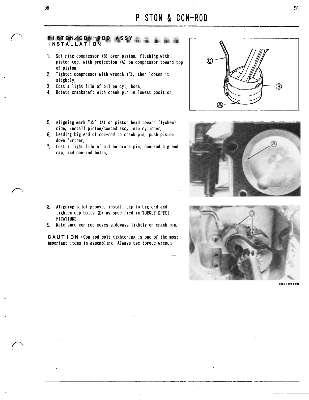
56
1.
Set ring compressor
piston top, with projection
of piston.
2.
Tighten compressor with wrench
slightly.
3.
Coat a light film of oil on cyl. bore.
4.
Rotate crankshaft
5.
Aligning mark
side, instal
6.
Leading big end of con-rod to crank pin, push piston
down further.
7.
Coat a light film of oil
cap, and con-rod bolts.
1
(B)
over piston, flushing
(A)
on compressor toward top
(C),
then loosen
with
crank pin
(A)
on piston head toward flywheel
piston/conrod assy into cyl inder.
on
in
lowest pos
crank pin, con-rod big end,
with
it
it
ion.
56
ligning pilot groove. install cap to big end and
a.
A
ighten cap bolts
t
F
I
CAT
IONS.
9.
Make sure con-rod moves sideways lightly on crank pin.
C
AUT
I 0 N
:
important items
(D)
as specified
Con-rod bolt tightening
in
assembling. Always use torque wrench.
in
TORQUE
is
SPECI-
one of the most
E36FCZIW3
Page 64

57
CRANKSHAFT
Check crank pin part and bearing journals for score,
wear, or corrosion.
If crank pin part shows any damage, carefully check
con-rod big end and repair or replace con-rod and/or
crankshaft. (See CON-ROD
Check crank gear for worn or broken teeth.
If excessively worn or broken teeth are observed, re-
place crank gear.
VISUAL
CHECK.
)
57
E37FCOZW2
Page 65

58
58
CRANKSHAFT
Check outside diameter of crank pin
2.
points with micrometer.
If outside diameter
replace crankshaft.
3.
Check run out of crankshaft at both bearing journals
with dial indicator
jig
(B).
If total reading of run out
(0.008
in.), replace crankshaft.
is
less
than
(A),
setting crankshaft to alignment
is
(A)
at several
27.920
more than
mm
(1.0992
0.20
in.),
mm
1.
Install key
2.
Install crank gear
3.
Make sure end
surf ace (C)
4.
Coat a film of oil on bearing surfaces of crankshaft.
5.
Tape key way at taper of crankshaft to avoid cutting of
oil seal
6.
Pack some amount of grease for high temperature application into oil seal.
(A)
of
lips.
as shown.
(B)
as timing mark facing outside.
key
is
not projecting from crank gear
E37FCO7W3
Page 66

-59
1.
Re-grind crank pin to
0.5
mm under size.
59
CRANKSHAFT
NOT E :
0.005
mm
22.950 23.00
27.467 27.480
1.5
-24.00
Crank pin must be concentric and parallel within
(0.0002
in.) full indicator reading, and surface
1.8
mm
24.10
mm
(0.9035 0.9055
mm
(1.0814 1.0819
(0.059 0.071
mm
(0.945 0.949
in.
in.
in.
in.)
)
must be finished very smooth with super finishing stone.
C
A
UT I 0
N
:
If crank pin
is
re-ground, under-size con-
rod must be used to keep specified clearance.
E37FCOSW2
Page 67

60
1.
Check governor gear assy for wear and damage, as in-
stalled in crankcase cover.
C
A
UT
I
0
N
:
Do
not remove governor gear assy from crank-
If
case cover exceot to reolace~
re-used.
2.
If governor gear assy
(A)
with proper size screw drivers
C
A
U T
I
0
N
:
Do
not damage gasket surface by screw
drivers.
once removed.
must be replaced, remove
(B).
GOVERNOR
it
cannot be
it
60
1.
Place sleeve
C
A
UT I
0
(A)
into governor gear assy
N
:
Sleeve can not be assembled after governor
(B).
gear assy installed in crankcase cover.
2.
Place thrust washer (C) on boss of shaft
(B)
install governor gear assy
until1 step
3.
Check free rotation of governor assy after installation.
1.
Install governor shaft
ing pin
NOT
E
:
projection (C) which
(E)
fits into groove
(A)
(B)
to governor shaft positioning as shown.
Be careful for position of locking pin end and
is
stopper of governor shaft
with sleeve
(F).
into crankcase and set lock-
(D)
and then
(A)
to shaft
(A).
E39FC04W2
E39FCOZWI
E39PCOSYI
Page 68

61
61
LUBR
NOT
E
:
Detergent engine oil delays formation of gum and
Do
varnish.
2.
Select oil viscosity depending on expected environmental
temperature as shown.
not add any additives to detergent oil.
I
CAT
I
NG
SYSTEM
-20°c
-4°F
-10°c
14°F
0°c
32°F
IO°c
5O°F
20°c
68°F
30°c
86’°F
E4OPCOIWI
40°C
104°F
If slinger
Function of breather
ing oil being forced
Reed valve controls direction of air flow caused by piston
movement
reed valve but not from outside to inside.
Oil laden air in crankcase passes through first reed valve
(A) and expands in valve chamber, where some portion
is
separated from air and returns to crankcase through hole
(B)
.
The
air passes through second reed valve
breather chamber (D), where remained oil
air and drain to valve chamber through hole
Then air passes through maze in breather chamber (D) and
vented to intake pipe through tube
is
damaged, replace
is
to keep vacuum
out
of engine.
so
that air flow from inside to outside can pass
it.
in
crankcase avoid-
of
oil
(C)
and expands
is
separated from
in
(E).
is
(G).
E4OFCIOWI
E4OFC11W2
Page 69

62
62
1.
Check valve and valve seat
or
wear.
2.
Install reed valve
tool
(C),
and check gap between reed valve
surface (C) with feeler gauge.
is
If gap
or
replace valve.
more than
(A)
and back plate
0.2
mm
LUBR
for
any damage such as crack
(0.008
in.). turn over valve
I
CAT
I
NG
(B)
on inspection
(A)
and tool
SYSTEM
EIOFC12WI
Page 70

63
CYL
I
1.
Visually check cyl. block for scored bore, broken fin,
or
other damages.
63
__-
If unrepairable damage
2.
Check inside diameter at
directions of parallel and right angle to crankshaft,
with inside micrometer.
If
inside diameter and/or out of round are more than
resize cyl. bore
CYL.
CYL.
BORE INSIDE DIA.
BORE OUT
is
observed, replace cy]. block.
10
mm
(0.4
or
replace cyl. block.
OF
ROUND
in.) from top in
MAX,
MAX
MAX
E41FC06W2
Oversize piston and piston rings
(0.01
in.),
0.50
mm
(0.02
in.), and
available. Select suitable size depending on condi
cyl.
bore
to
be re-sized.
1.
Bore cylinder finely to size as shown on right
i
before hon
S.
B.S. : Boring Size
ng.
:
Over Size
for
standard plus
0.75
mm
(0.03
0.25
mm
in.) are
tion
of
table
Page 71

64
CYL I NDER/CRANKCASE
2.
Hone cylinder to final size as shown on right table
following procedure shown below.
C
A
UT I
0
N
:
Consider shrinkage of cyl. bore for
0.008
mm
(0.0002-0.0003
in.) after cooling down from honing
heat.
F.S.
:
Final Size
N 0 T
E
:
Use honing stone recommended by hone manufacturer.
(1)
A1ign
centers of cyl. bore and drill press carefully
and-set cyl. block on drill press table.
(2)
Install hone to drive shaft and set stopper of dril
press
so
that hone can only extend
20-25
mm
from top to bottom of cyl. bore.
(3)
Adjust honing stone to contact snugly against cyl.
narrowest point.
DO
NOT
FORCE.
(4)
Rotate hone by hand. If it cannot be rotated, adjust
hone until it can be rotated by hand.
(5)
Set dri11 press rpm to
(6)
Coat honing
oil
on cyl. bore.
200 250.
0.006-
(3/4-1
11
in.
)
wall at
0.25
0.50
0.75
mm
mm
mm
F.
S.
65.230 65.250
mm
(2.5681 2.5689
65.480 65.500
mm
(2.5779 2.5787
65.730 65.750
mm
(2.5878 2.5886
64
in.
in.
in.
C
A
UT I
0
N
:
Do not use solvent or gasoline.
(7)
Drive drill press and move hone up and down in cyl. bore
about
20
cycles/minute.
W
A R N I N
G
:
Stop drill press when checking
or
mea-
suring cyl. bore.
(8)
Measure inside diameter in suitable periods with inside
micrometer, and check finishing pattern which should be
40
to
60
degrees crosshatch.
(9)
Clean cyl. block thoroughly with soap and warm water for
“white glove inspection”.
C
AUT
I
0
N
:Thoroughly wash honing grit from cylinder.
Grit
is
extremely abrasive to engine components.
(10)
Dry cyl. block and coat engine
oil
to cyl. bore.
E4lFC07W6
Page 72

65
CYL
I
NDER/CRANKCASE
C
AUT
I
ON
:Do
not remove ball bearing from housing
except replacing.
1.
Clean ball bearing with high flash point solvent.
2.
Pour engine
3.
Rotate bearing inner race slowly by hand.
oil
to bearing.
65
If any roughness
re-cleaning, replace ball bearing.
is
felt and
it
can not be removed by
r-
1.
Remove oil seal preceding ball bearing replacement.
Do
not re-use removed oil seal.
2.
Push out ball bearing with bearing driver.
3.
Clean bearing housing
dry
and
4.
Coat a light film of
5.
Push new ball bearing into housing to end.
If
oil leakage through oil seal
damaged, replace oil seal.
1.
Remove oil seal by tapping
punch.
2.
Placing spring held seal lip
into housing until seal outside surface becomes flush
with housing end (C).
3.
Before final assembly, pack some amount of grease for
high temperature application into space between seal lip
(A)
it.
and dust 1 ip
(B).
with
high flash point solvent
oil
on bearing.
is
observed
it
out
(A)
inside, push oil seal
or
seal lip
with
screw driver
is
or
E4IFC03WI
EIIFCO4WI
Page 73

66
66
If
inside diameter
llace cy1 inder/crankcase.
rep
is
more than
CY
14.070
mm
NDER/CRANKCASE
(0.5539
in.
),
E4IFCOIWI
Page 74
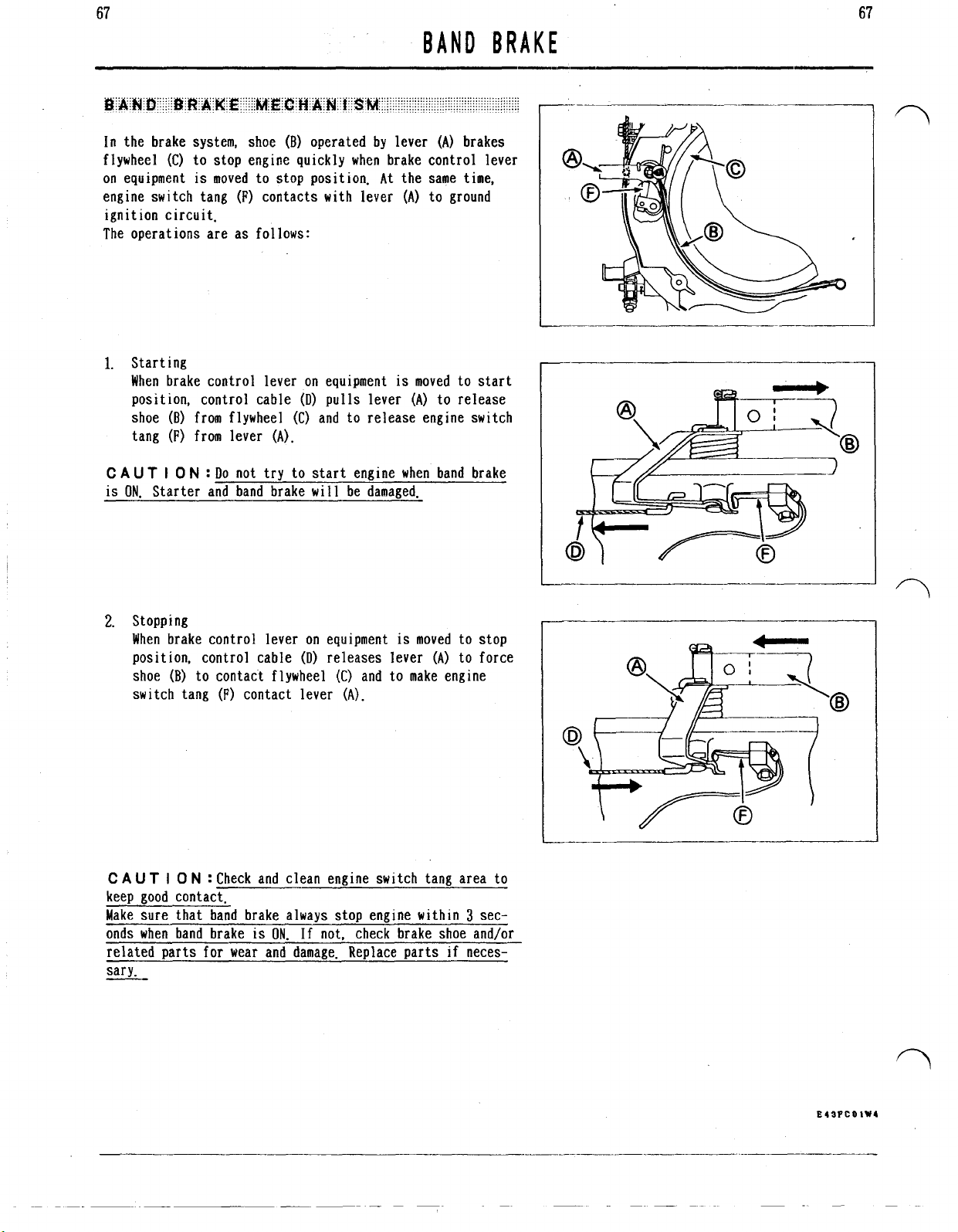
67
67
BAND BRAKE
In the brake system, shoe
flywheel
on equipment
engine switch tang
(C)
to stop engine quickly when brake control lever
is
moved to stop position. At the same time,
(F)
(B)
operated by lever
contacts with lever
ignition circuit.
The operations are as follows:
1.
Starting
When brake control lever on equipment
position, control cable
shoe
(B)
from flywheel (C) and to release engine switch
tang
(F)
from lever
C
A
UT
I
0
N
:
Do
not try to start engine when band brake
is
ON.
Starter and band brake
(A).
(D)
pulls
will
lever (A) to release
be damaged.
(A)
brakes
(A)
to ground
is
moved to start
I
2.
Stopping
When brake control lever
position, control cable
shoe
(B)
to contact flywheel
(F)
switch tang
C
A
UT
I
0
N
contact lever
:
Check and clean engine switch tang area to
on
equipment
(D)
releases lever
(C)
and to make engine
(A).
is
moved to stop
(A)
to force
keep good contact.
3
Make sure that band brake always stop engine within
onds when band brake
is
ON.
If not, check brake shoe and/or
sec-
related parts for wear and damage. Replace parts if necessary.
Page 75

68
BAND BRAKE
1.
Do
not remove brake shoe
replacing the shoe.
2.
If stud
(G)
is
removed to replace shoe
ing agent on the thread when reinstalling the stud.
3.
Shoe
(B)
does not requ
Operate brake control lever on equipment and check brake
cable for any slack. If necessary, adjust brake cable con-
nect ion.
1.
Release brake control lever on equipment.
2.
Loosen outer cable clamp bolt
to
remove any slack.
3.
Then tighten clamp bolt
(B)
from stud
(G)
(B),
ire adjustment
(A).
in installation.
(A)
and pull outer cable
except when
apply lock-
68
E43FC02WI
I
E43FCO3WI
t
Page 76

 Loading...