

Page 1

Form No. 3325-516
Super Recycler
Mower
Model No. 20042–210000001 and Up
Model No. 20043–210000001 and Up
Parts Catalog
Ordering Replacement Parts
To order replacement parts, please supply: the part
number, the quantity, and the description of each
part desired.
Understanding Reference Numbers
Each identified part in an illustration has a reference
number. The reference number for a part also appears in
the parts list, along with other information about the part.
This catalog uses two special reference number formats,
one to indicate parts in a service assembly and another
to indicate the quantity of a given part in an illustration.
Service Assembly Reference Numbers
Parts in service assemblies have reference numbers in
the form a:b.
the entire service assembly and the b represents a
sequential number unique to each part within the service
assembly.
The a represents the reference number of
The TORO Company — 2001
All Rights Reserved
For example, a wheel assembly might be identified by
reference number 6, the tire by 6:1, the valve by 6:2,
and the wheel by 6:3. When you order the assembly
identified by reference number 6, you receive all parts
identified by reference numbers 6:1, 6:2, and 6:3.
However, you may also order any part individually.
Reference numbers of this type appear in illustrations
and in part lists.
Reference Numbers Indicating Quantity
In an illustration, if a reference number indicates more
than one part, the reference number has the form nX y.
The n represents the quantity of the part, the X is the
multiplication symbol, and the y represents the reference
number.
For example, in an illustration, the reference number
2X 37 means that two of the parts identified by reference
number 37 are indicated.
Page 2

3325–516
Contents
Description Page Description Page
Housing, Handle Brackets, and Wheel Assembly 3
Gear Case Assembly 4. . . . . . . . . . . . . . . . . . . . . .
Gear Case Assembly 5. . . . . . . . . . . . . . . . . . . . . .
Engine and Blade Assembly 6. . . . . . . . . . . . . . . .
Handle and Controls Assembly 7. . . . . . . . . . . . . .
Rear Bagging Discharge Chute Assembly 8. . . .
Rear Bagger Assembly 11–0189 9. . . . . . . . . . . .
ENGINE BRIGGS & STRATTON MODEL
12H802–1776–B1 10. . . . . . . . . . . . . . . . . . . . . . .
ENGINE BRIGGS & STRATTON MODEL
12H802–1776–B1 11. . . . . . . . . . . . . . . . . . . . . . .
ENGINE BRIGGS & STRATTON MODEL
12H802–1776–B1 12. . . . . . . . . . . . . . . . . . . . . . .
ENGINE BRIGGS & STRATTON MODEL
12H802–1776–B1 13. . . . . . . . . . . . . . . . . . . . . . .
ENGINE BRIGGS & STRATTON MODEL
12H802–1776–B1 14. . . . . . . . . . . . . . . . . . . . . . .
ENGINE BRIGGS & STRATTON MODEL
12H802–1776–B1 15. . . . . . . . . . . . . . . . . . . . . . .
ENGINE BRIGGS & STRATTON MODEL
12H802–1776–B1 16. . . . . . . . . . . . . . . . . . . . . . .
ENGINE BRIGGS & STRATTON MODEL
12H802–1776–B1 17. . . . . . . . . . . . . . . . . . . . . . .
ENGINE BRIGGS & STRATTON MODEL
12H802–1776–B1 18. . . . . . . . . . . . . . . . . . . . . . .
Accessories
Description Model / Part No. Description Model / Part No.
Recycler Side Discharge Kit 59197. . . . . . . . . . . . . . . .
Dethatcher Kit 59131. . . . . . . . . . . . . . . . . . . . . . . . . . . .
Recycler Bagging Kit 59195. . . . . . . . . . . . . . . . . . . . . .
Traction Assist Handle Kit 59196. . . . . . . . . . . . . . . . . .
Part Description Abbreviations
Part descriptions in this catalog may include the following abbreviations.
Abbreviation Meaning Abbreviation Meaning
AR as required. . . . . . . . . . . . . . . . .
ASM assembly. . . . . . . . . . . . . . . .
CARR carriage. . . . . . . . . . . . . .
DEG degrees. . . . . . . . . . . . . . . .
FH flat head. . . . . . . . . . . . . . . . .
GA gauge. . . . . . . . . . . . . . . . .
HF hex flange. . . . . . . . . . . . . . . . .
HH hex head. . . . . . . . . . . . . . . . .
HHF hex head flange. . . . . . . . . . . . . . . .
HLH hex lag head. . . . . . . . . . . . . . . .
HJ hex jam. . . . . . . . . . . . . . . . . .
HOC height-of-cut. . . . . . . . . . . . . . . .
HS hex socket. . . . . . . . . . . . . . . . .
HSBH hex socket button head. . . . . . . . . . . . . .
HSFH hex socket flat head. . . . . . . . . . . . . . .
HSH hex socket head. . . . . . . . . . . . . . . .
HWH hex washer head. . . . . . . . . . . . . . .
HWHTF hex washer head. . . . . . . . . . . . .
thread forming
HYD hydraulic. . . . . . . . . . . . . . . .
INC incorporated. . . . . . . . . . . . . . . . .
LH left hand. . . . . . . . . . . . . . . . .
NI nylon insert. . . . . . . . . . . . . . . . . .
PPH Phillips pan head. . . . . . . . . . . . . . . .
PTH Phillips truss head. . . . . . . . . . . . . . . .
PTO power take off. . . . . . . . . . . . . . . .
RH right hand. . . . . . . . . . . . . . . . .
SFH slotted fillister head. . . . . . . . . . . . . . . .
SHH slotted hex head. . . . . . . . . . . . . . . .
SQH square head. . . . . . . . . . . . . . . .
SHWH slotted hex washer head. . . . . . . . . . . . . .
SPH slotted pan head. . . . . . . . . . . . . . . .
SRH slotted round head. . . . . . . . . . . . . . . .
STD standard. . . . . . . . . . . . . . . .
TAP self tapping. . . . . . . . . . . . . . . .
TTH Torx truss head. . . . . . . . . . . . . . . .
WH wing head. . . . . . . . . . . . . . . . .
2
Page 3
7:4
15
14
13
12
7:6
7:5
8
16
10
18
19
20
7:8
22
23
24
25
26
3325–516
28
27
28
7
7:3
5
2
4
3
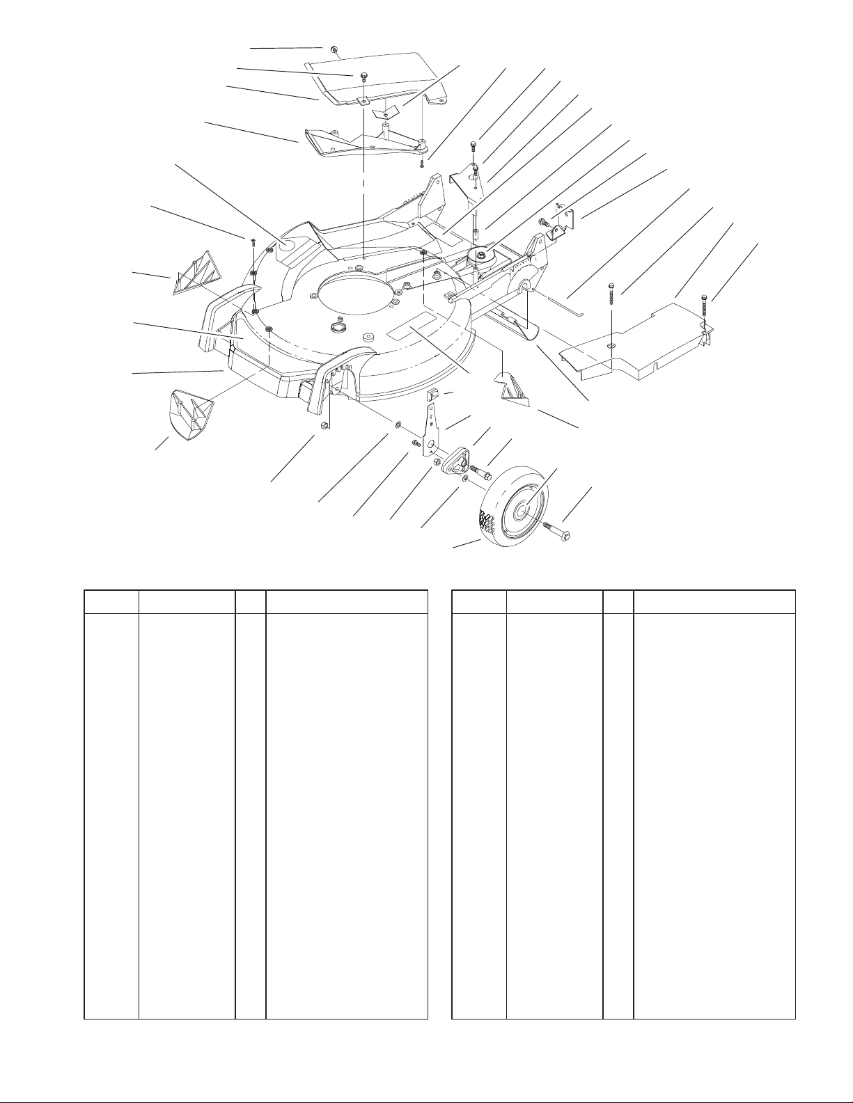
Housing, Handle Brackets, and Wheel Assembly
DescriptionPart No. Qty.Ref. No. DescriptionPart No. Qty.Ref. No.
1 98–7130 2 Wheel ASM
1:1 27–6250 2 Bushing
2 40–1940 4 Washer
3 603773 2 Nut
4 32144–85 2 Screw–HH
5 3296–6 2 Nut–Lock, NI
7 98–7148 1 Housing – Service
7:2 92–1750 1 Kicker–Rear
7:3 92–1720 1 Kicker–Front
7:4 92–1730 1 Kicker–RH
7:5 32144–111 6 Screw–PPH
7:6 43–8480 1 Decal–Danger
7:7 93–0248 1 Decal – Warning
7:8 99–6018 1 Decal – Warning
8 99–6010 1 Decal – Deck
12 82–8620 1 Deflector (only on:
20042)
13 100–8775 1 Recycler Cover ASM
(only on: 20042)
13:2 32144–111 5 Screw–PPH (only on:
20042)
14 46–6811 3 Screw–HWH (only
on: 20042)
15 46–6810 1 Screw & Washer ASM
(only on: 20042)
7:7
32
33
34
35
1:1
2
1
29
7:2
36
Sheet No.:2
16 83–4750 1 Cover Guard (only on:
20042)
18 49–2040 1 Screw–Tapping
19 92–1616 1 Screw–HWHTF
20 99–1513–03 1 Bracket–Transmission
Actuator
22 614673 1 Bushing–Plate,
Actuator
23 104–7674 1 Gear Case ASM
24 32144–70 1 Screw–HH
25 99–1512–03 1 Bracket–Cable,
Traction
26 33–3208 1 Rod–Shield
27 104–7906 1 Cover–Belt,Tc
28 37–7260 2 Screw–HH
29 44–0580 1 Shield–Trailing
32 25–7740 2 Knob–Arm
33 66–0541 2 Spring Arm
ASM–Front
34 66–0580 2 Arm–Pivot, Front
35 66–0560 2 Bolt–Shoulder
36 92–1057 2 Bolt–Shoulder
3
Page 4

3325–516
20
10
9
8:2
8:4
8
4
3
7
5
6
4
3
11
12
13
8:3
14
15
Gear Case Assembly
DescriptionPart No. Qty.Ref. No. DescriptionPart No. Qty.Ref. No.
1 92–1057 2 Bolt–Shoulder
2 98–7135 2 Wheel ASM
2:3 1 Wheel ASM
2:3:1 27–6250 2 Bushing
3 65–2720 4 Ring–Klip
4 65–4740 4 Washer–Thrust,
Keyed
5 66–6040 1 Key–Rocking, RH
6 66–6050 1 Key–Rocking, LH
7 65–4710 2 Ring–Friction
8 100–8774 2 Pivot Arm ASM
8:2 47–2900 1 Bushing
8:3 70–9760 1 Bushing
8:4 302–56 1 Fitting–Zerk
9 25–7740 2 Knob–Arm
10 42–3520 2 Cap–End
11 32144–85 2 Screw–HH
12 63–8721 2 Spring Arm ASM
13 603773 2 Nut
14 65–4730 2 Washer–Arm, Pivot
15 65–4760 2 Washer–Clutch
16 65–4750 2 Gear–Pinion
17 65–4720 2 Spring–Compression
18 74–1660 2 Cover–Wheel
19 74–1671 2 Spacer–Cover, Wheel
20 91–2258 1 V–Belt
16
17
18
2
2:1
1
19
Sheet No.:3
4
Page 5
13
3325–516
7
5
19
6
10
15
4
12
1
11
14
17
8
9
10
18
8
11
16
2
3
Sheet No.:A1
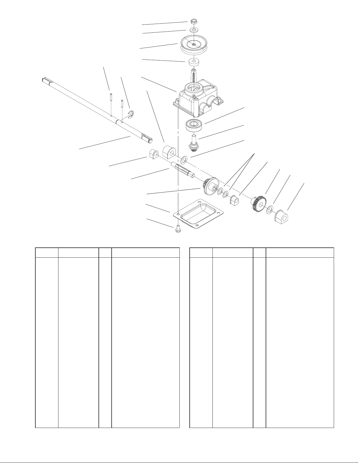
Gear Case Assembly
DescriptionPart No. Qty.Ref. No. DescriptionPart No. Qty.Ref. No.
1 104–7619 1 Casting–Gear Case
2 614668–03 1 Cover–Gear Case
3 32144–4 4 Screw–HWH
4 32151–68 1 Ring–Retaining
5 3256–24 1 Washer–Flat
6 3285–19 2 Pin–Groove
7 3296–5 1 Nut–Lock NI
8 36–4780 2 Washer
9 36–4791 2 Washer–Thrust
10 60–8750 2 Bushing
11 60–8850 2 Bushing–Output
12 614696 1 Shaft–Intermediate
13 100–1176 2 Pulley–Half
14 100–1048 1 Bearing–Ball
15 62–6660 1 Spacer
16 104–1005 1 Gear–19t Spur, 37t
Bevel
17 104–7667 1 Gear–Pinion,Bevel
18 104–1004 1 Gear–30t
19 104–7673 1 Shaft–Output
5
Page 6
3325–516
8
7
6
9
10
R
4
3
2
1
15
16
17
18
11
12
13
14
Sheet No.:4
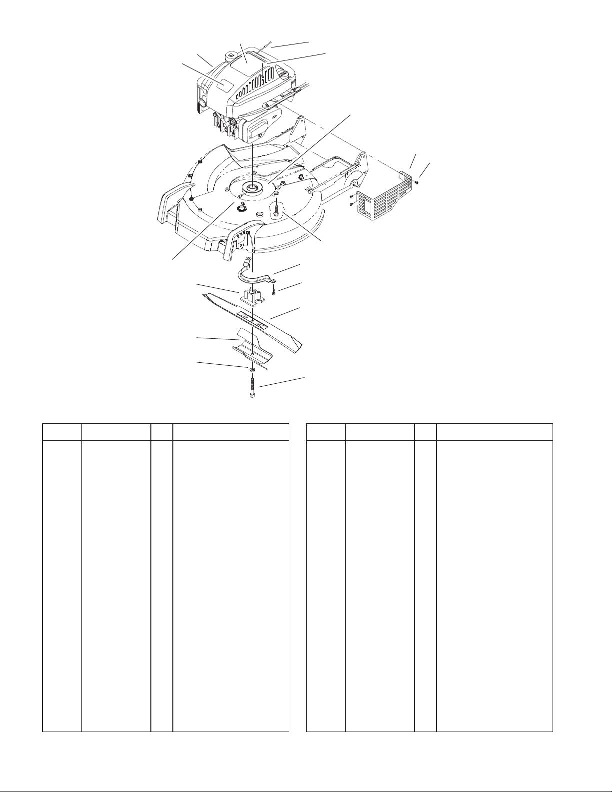
Engine and Blade Assembly
DescriptionPart No. Qty.Ref. No. DescriptionPart No. Qty.Ref. No.
1 3253–22 1 Washer–Lock
2 94–1608–03 1 Accelerator–Blade
3 104–1007 1 Retainer–Blade
4 104–0214 1 Screw–Set,Cone Point
6 98–3206 1 Nameplate – Toro
7 93–0243 1 Shroud–Quantum
Wedge
8 99–6013 1 Decal – Recoil
9 2210–316 1 Stop–Rope
10 32144–121 2 Screw–PPH
11 95–1878 1 Pulley
12 104–7577–03 1 Shield–Muffler
13 32144–1 3 Screw–Taptite
14 32144–102 3 Screw–HWH
15 66–0570–03 1 Bracket–Guide, Belt
16 32144–70 2 Screw–HH
17 93–4106–03 1 Blade–21”, Recycler
18 95–1748 1 Screw–Blade
6
Page 7

3325–516
1
16
22
20
23
24
25
24
26
27
14
28
29
8
30
17
31
32
2
3
4
5
6
7
8
29
9
11
12
13
14
24
26
15
24
16
22
20
17
18
2121
1920
Sheet No.:8
Handle and Controls Assembly
DescriptionPart No. Qty.Ref. No. DescriptionPart No. Qty.Ref. No.
1 99–1593–03 1 Bail–Brake
2 99–1582 1 Handle–Control
3 99–1595 1 Retainer–Cable, Brake
4 46–8091 1 Screw–HWH
5 99–1589 1 Lever–Traction
6 99–1588 1 Bar–Control, Traction
7 99–6008 1 Retainer–Control Rod,
Traction
8 94–4496 10 Screw–PPH
9 100–1186 1 Cable–Brake
11 95–4453 1 Screw–Handle
12 99–5239 1 Anchor–Cable
13 3256–1 1 Washer–Flat
14 3296–73 2 Nut–Lock, NI
15 99–1584 1 Cable–Traction
16 99–5248–03 2 Latch–Handle
17 27–7210 2 Screw–Shoulder
18 100–2894 1 Tie–Cable
19 3296–47 1 Nut–Lock, NI
20 3296–72 3 Nut–Lock, NI
21 3–3287 2 Spacer–Latch, Handle
22 27–7211 2 Screw–Shoulder
23 99–5249–05 1 Handle–Lower
24 98–7134 4 Knob–Handle
25 99–6019 2 Screw–CARR
26 92–2260 2 Screw–Handle
27 99–1596–05 1 Handle–Upper
28 86–9671 1 Guide–Rope
29 99–1590 2 Guide–Handle, Control
30 99–6339 1 Cover–Handle
31 99–1592 1 Spring–Torsion, RH
32 99–6009 1 Decal – Console
7
Page 8

3325–516
9
3
2
1
4
5
8
Rear Bagging Discharge Chute Assembly
DescriptionPart No. Qty.Ref. No. DescriptionPart No. Qty.Ref. No.
1 82–9153 1 Discharge Tunnel (only
on: 20043)
2 93–7351 1 Discharge Door ASM
(only on: 20043)
3 76–4660 1 Spring–Door (only on:
20043)
4 93–3154 1 Latch–Plate (only on:
20043)
5 46–8090 2 Screw–Plastite (only
on: 20043)
6 80–3770 1 Retainer–Door (only
on: 20043)
7 71–9350 1 Bracket–Spring (only
on: 20043)
8 46–6811 3 Screw–HWH (only
on: 20043)
9 46–6810 1 Screw & Washer ASM
(only on: 20043)
* 77–0500 1 Discharge Plug ASM
(only on: 20043)
* 3295–35 1 Rivet–Head, Flat (only
on: 20043)
* 76–2110 1 Plug–Discharge (only
on: 20043)
* 76–4640 1 Latch–Plug, Discharge
(only on: 20043)
67
Sheet No.:10
* 76–4650 1 Grip–Latch (only on:
20043)
* Not illustrated
8
Page 9

3325–516
6
5
4
3
2
1
Rear Bagger Assembly 11–0189
DescriptionPart No. Qty.Ref. No. DescriptionPart No. Qty.Ref. No.
1 3290–422 2 Nut–Push (only on:
20043)
2 37–1393 1 Door–Bag (only on:
20043)
3 42–4020 1 Frame–Bag (only on:
20043)
4 36–6910 2 Spring (only on:
20043)
5 42–4030 1 Frame–Bag, Upper
(only on: 20043)
6 44–0522 1 Bag–Grass (only on:
20043)
7 33–4820 1 Hinge–Door, Bag
(only on: 20043)
7
Sheet No.:11
9
Page 10

3325–516
585
50
635
383
584
337
51
13
54
684
REQUIRES SPECIAL TOOLS
TO INSTALL. SEE REPAIR
INSTRUCTION MANUAL.
7
5
869
1
2
3
870
307
1019 LABEL KIT
306
871
8
287
9
847
523
842
525
524
11
10
Assemblies include all parts shown in frames.
1058 OWNER’S MANUAL
ENGINE BRIGGS & STRATTON MODEL 12H802–1776–B1
DescriptionPart No. Qty.Ref. No. DescriptionPart No. Qty.Ref. No.
1 493260 1 Cylinder Assembly
2 399269 1 Bearing/Seal Kit
(Magneto Side)
3 299819 1 Oil Seal (Magneto
Side)
5 691160 1 Cylinder Head
∆7 692249 1 Cylinder Head Gasket
8 695250 1 Breather Assembly
∆9 272481 1 Breather Gasket
10 691125 1 Screw (Breather
Assembly)
11 691781 1 Breather Tube
13 690912 1 Screw (Cylinder Head)
50 497465 1 Intake Manifold
51 272199 1 Intake Gasket
54 691650 1 Screw (Intake
Manifold)
287 690940 1 Screw (Dipstick Tube)
306 690450 1 Cylinder Shield
307 690345 1 Screw (Cylinder Shield)
337 802592 1 Sparkplug
383 89838 1 Sparkplug Wrench
523 495264 1 Dipstick
524 692296 1 Dipstick Tube Seal
525 495265 1 Dipstick Tube
584 692342 1 Breather Passage
Cover
585 691879 1 Breather Passage
Gasket
635 66538 1 Sparkplug Boot
684 690345 1 Screw (Breather
Passage Cover)
842 691031 1 O Ring Seal
(Dipstick Tube)
847 692017 1 Dipstick/Tube
Assembly
869 691155 1 Valve Seat
1 (Intake)
870 690380 1 Valve Seat
(Exhaust)
871 262001 1 Guide Bushing
(Exhaust)
63709 1 Guide Bushing
(Intake)
1019 494256 1 Label Kit
1058 274783 1 Owner’s Manual
∆ Included in Valve Gasket Set–Ref. 1095. Included in Carburetor Overhaul Kit–Ref. 121.
Included in Engine Gasket Set–Ref. 358. Included in Carburetor Gasket Set–Ref. 977
10
Page 11

3325–516
46
4
12
43
20
25
26
27
22
29
32
28
32A
27
45
40
35
34
45
40
36
33
16
24
146
741
15
Assemblies include all parts shown in frames.
ENGINE BRIGGS & STRATTON MODEL 12H802–1776–B1
DescriptionPart No. Qty.Ref. No. DescriptionPart No. Qty.Ref. No.
4 493279 1 Engine Sump
12 692232 1 Crankcase Gasket
15 691680 1 Oil Drain Plug
16 696009 1 Crankshaft
20 399781 1 Oil Seal (PTO Side)
22 691092 1 Screw (Engine Sump)
24 222698 1 Flywheel Key
25 499429 1 Piston Assembly
(Standard)
499430 1 Piston Assembly
(.010” Oversize)
499431 1 Piston Assembly
(.020” Oversize)
499432 1 Piston Assembly
(.030” Oversize)
26 499425 1 Ring Set
(Standard)
499426 1 Ring Set
(.010” Oversize)
499427 1 Ring Set
(.020” Oversize)
499428 1 Ring Set
(.030” Oversize)
27 691866 1 Piston Pin Lock
28 499423 1 Piston Pin (Standard)
298908 1 Piston Pin (.005” O.S.)
29 499424 1 Connecting Rod
(Standard)
32 691664 Screw
1 (Connecting Rod)
32A 695759 1 Screw
(Connecting Rod)
33 262651 1 Exhaust Valve
34 262652 1 Intake Valve
35 691270 1 Valve Spring (Intake)
36 691270 1 Valve Spring (Exhaust)
40 692194 1 Valve Retainer
43 691997 1 Governor/Oil Slinger
45 690548 1 Valve Keeper
46 691449 1 Camshaft
146 690979 1 Timing Key
741 691830 1 Timing Gear
∆ Included in Valve Gasket Set–Ref. 1095. Included in Carburetor Overhaul Kit–Ref. 121.
Included in Engine Gasket Set–Ref. 358. Included in Carburetor Gasket Set–Ref. 977.
11
Page 12

3325–516
365
125
163
97
633
127
134
130
95
133
104
975
137
276
617
117
276
Assemblies include all parts shown in frames.
ENGINE BRIGGS & STRATTON MODEL 12H802–1776–B1
DescriptionPart No. Qty.Ref. No. DescriptionPart No. Qty.Ref. No.
95 691636 1 Screw (Throttle Valve)
97 493267 1 Throttle Shaft
104 691242 1 Float Hinge Pin
117 494870 1 Main Jet (Standard)
497315 1 Main Jet (High Altitude)
125 498170 1 Carburetor
127 694468 1 Welch Plug
130 691203 1 Throttle Valve
133 398187 1 Carburetor Float
134 398188 1 Needle/Seat Kit
137 693981 1 Float Bowl Gasket
163 272653 1 Air Cleaner Gasket
276 271716 1 Sealing Washer
365 692524 1 Screw (Carburetor)
617 270344 1 O Ring Seal (Intake
Manifold)
633 691321 1 Choke/Throttle Shaft
Seal
975 493640 1 Float Bowl
∆ Included in Valve Gasket Set–Ref. 1095. Included in Carburetor Overhaul Kit–Ref. 121.
Included in Engine Gasket Set–Ref. 358. Included in Carburetor Gasket Set–Ref. 977.
12
Page 13

3325–516
209
202
227
562
505
615
404
616
745
621
188
222
923
922
668
334
333
Assemblies include all parts shown in frames.
851
ENGINE BRIGGS & STRATTON MODEL 12H802–1776–B1
DescriptionPart No. Qty.Ref. No. DescriptionPart No. Qty.Ref. No.
188 690877 1 Screw (Control
Bracket)
202 691829 1 Mechanical Governor
Link
209 691292 1 Governor Spring
222 692467 1 Control Bracket
227 690783 1 Governor Control
Lever
333 802574 1 Magneto Armature
334 691061 1 Screw (Magneto
Armature)
404 690272 1 Washer (Governor
Crank)
505 231082 1 Nut (Governor Control
Lever)
562 92613 1 Screw (Governor
Control Lever)
615 690340 1 Governor Shaft
Retainer
616 691306 1 Governor Crank
621 692310 1 Stop Switch
668 493823 1 Spacer
(Includes 2)
745 691648 1 Screw (Brake)
851 493880 1 Sparkplug Terminal
922 691831 1 Brake Spring
923 691994 1 Brake
∆ Included in Valve Gasket Set–Ref. 1095. Included in Carburetor Overhaul Kit–Ref. 121.
Included in Engine Gasket Set–Ref. 358. Included in Carburetor Gasket Set–Ref. 977.
13
Page 14

3325–516
968
425
445
966
159
970
529
443
163
976
Assemblies include all parts shown in frames.
ENGINE BRIGGS & STRATTON MODEL 12H802–1776–B1
DescriptionPart No. Qty.Ref. No. DescriptionPart No. Qty.Ref. No.
159 691753 1 Air Cleaner Primer
Bracket
163 272653 1 Air Cleaner Gasket
425 690670 1 Screw (Air Cleaner
Cover)
443 692523 1 Screw (Air Cleaner
Primer Base)
445 491588 1 Air Cleaner Cartridge
Filter
529 691923 1 Grommet
966 496116 1 Air Cleaner Primer
Base
968 692298 1 Air Cleaner Cover
970 691669 1 Screw (Air Cleaner
Primer Bracket)
976 694395 1 Carburetor Primer
∆ Included in Valve Gasket Set–Ref. 1095. Included in Carburetor Overhaul Kit–Ref. 121.
Included in Engine Gasket Set–Ref. 358. Included in Carburetor Gasket Set–Ref. 977.
14
Page 15

3325–516
300
676
187
81
677
613
190
972
1059
670
957
601
Assemblies include all parts shown in frames.
ENGINE BRIGGS & STRATTON MODEL 12H802–1776–B1
DescriptionPart No. Qty.Ref. No. DescriptionPart No. Qty.Ref. No.
81 691740 1 Muffler Screw Lock
187 691050 1 Fuel Line
(Cut to Required
Length)
190 690940 1 Screw (Fuel Tank)
300 496106 1 Muffler
601 95162 1 Hose Clamp
613 691340 1 Screw (Muffler)
670 692294 1 Fuel Tank Spacer
676 493871 1 Muffler Deflector
677 690661 1 Screw (Muffler
Deflector)
957 397974 1 Fuel Tank Cap
972 495224 1 Fuel Tank
1059 692311 1 Screw/Washer Kit
∆ Included in Valve Gasket Set–Ref. 1095. Included in Carburetor Overhaul Kit–Ref. 121.
Included in Engine Gasket Set–Ref. 358. Included in Carburetor Gasket Set–Ref. 977.
15
Page 16

3325–516
363
332
304
455
305
23
356
1036 EMISSIONS LABEL
Assemblies include all parts shown in frames.
ENGINE BRIGGS & STRATTON MODEL 12H802–1776–B1
DescriptionPart No. Qty.Ref. No. DescriptionPart No. Qty.Ref. No.
23 692315 1 Flywheel
304 493293 1 Blower Housing
305 691108 1 Screw (Blower
Housing)
332 690877 1 Nut (Flywheel)
356 692390 1 Stop Wire
363 19069 1 Flywheel Puller
455 691219 1 Flywheel Cup
1036 695111 1 Emissions Label
∆ Included in Valve Gasket Set–Ref. 1095. Included in Carburetor Overhaul Kit–Ref. 121.
Included in Engine Gasket Set–Ref. 358. Included in Carburetor Gasket Set–Ref. 977.
16
Page 17

3325–516
608
55
1211
1210
65
58
592
459
60
689
456
597
Assemblies include all parts shown in frames.
ENGINE BRIGGS & STRATTON MODEL 12H802–1776–B1
DescriptionPart No. Qty.Ref. No. DescriptionPart No. Qty.Ref. No.
55 691421 1 Rewind Starter
Housing
58 280399 1 Starter Rope
60 281434 1 Starter Rope Grip
65 690837 1 Screw (Rewind
Starter)
456 692299 1 Pawl Friction Plate
459 281505 1 Pawl Ratchet
592 690800 1 Nut (Rewind Starter)
597 691696 1 Screw (Pawl
Friction Plate)
608 497680 1 Rewind Starter
689 691855 1 Friction Spring
1210 498144 1 Pulley/Spring
Assembly (Pulley)
1211 498144 1 Pulley/Spring
Assembly (Spring)
∆ Included in Valve Overhaul Set–Ref. 1095. Included in Carburetor Overhaul Kit–Ref. 121.
Included in Engine Gasket Set–Ref. 358. Included in Carburetor Gasket Set–Ref. 977.
17
Page 18

3325–516
358 ENGINE GASKET SET
668
12
977 CARBURETOR
GASKET SET
163
137
617
633
524
163
7
9
3
20
1095 VALVE
GASKET SET
9
51
585
276
163
137
7
842
121 CARBURETOR
OVERHAUL KIT
134
127
617
633
104
Assemblies include all parts shown in frames.
ENGINE BRIGGS & STRATTON MODEL 12H802–1776–B1
DescriptionPart No. Qty.Ref. No. DescriptionPart No. Qty.Ref. No.
3 299819 1 Oil Seal (Magneto
Side)
∆7 692249 1 Cylinder Head Gasket
∆9 272481 1 Breather Gasket
12 692232 1 Crankcase Gasket
20 399781 1 Oil Seal (PTO Side)
51 272199 1 Intake Gasket
104 691242 1 Float Hinge Pin
121 498260 1 Carburetor Overhaul
Kit
127 694468 1 Welch Plug
134 398188 1 Needle/Seat Kit
137 693981 1 Float Bowl Gasket
163 272653 1 Air Cleaner Gasket
276 271716 1 Sealing Washer
358 497316 1 Engine Gasket Set
524 692296 1 Dipstick Tube Seal
585 691879 1 Breather Passage
Gasket
617 270344 1 O Ring Seal (Intake
Manifold)
633 691321 1 Choke Throttle Shaft
Seal
668 493823 1 Spacer (Includes 2)
842 691031 1 O Ring Seal (Dipstick
Tube)
977 498261 1 Carburetor Gasket Set
1095 498528 1 Valve Gasket Set
∆ Included in Valve Gasket Set–Ref. 1095. Included in Carburetor Overhaul Kit–Ref. 121.
Included in Engine Gasket Set–Ref. 358. Included in Carburetor Gasket Set–Ref. 977.
18
Page 19

Date
Maintenance Record
19
Page 20

 Loading...