

Page 1

TORO GTS 200 OVERHEAD VALVE ENGINE SERVICE MANUAL
Table of Contents – Page 1 of 2
SPECIFICATIONS
GENERAL INFORMATION
OIL
GASOLINE
COOLING SYSTEM
AIR CLEANER – GENERAL
AIR CLEANER SERVICE
TUNE-UP PROCEDURE
OVERHAUL PROCEDURE
CHECK-UP
EQUIPMENT AFFECTING ENGINE OPERATION
IGNITION
CHECK IGNITION
SPARK PLUG
REMOVE FLYWHEEL
INSPECT FLYWHEEL KEY, KEYWAYS, FLYWHEEL, AND CRANKSHAFT
INSTALL FLYWHEEL
SPECIFICATIONS
CARBURETION
CARBURETOR IDENTIFICATION
SERVICE CARBURETOR WALBRO LMS
GOVERNOR CONTROLS, CARBURETOR LINKAGE, AND FLYWHEEL BRAKE
REMOTE GOVERNOR CONTROLS
FLYWHEEL BRAKE
GOVERNOR ADJUSTMENTS
GOVERNOR AND CARBURETOR LINKAGES
GOVERNOR
GENERAL INFORMATION
GOVERNED RPM LIMITS
MECHANICAL GOVERNOR
COMPRESSION
TEST COMPRESSION
REMOVE CYLINDER HEAD
VALVE SERVICE
ASSEMBLE CYLINDER HEAD
SPECIFICATION TABLES
REWIND STARTER
GENERAL INFORMATION
REMOVE BLOWER HOUSING AND STARTER
Page 2

TORO GTS 200 OVERHEAD VALVE ENGINE SERVICE MANUAL
Table of Contents – Page 2 of 2
DISASSEMBLE REWIND STARTER
ASSEMBLE REWIND STARTER
ELECTRIC STARTER
GENERAL INFORMATION
TROUBLESHOOTING 12 VOLT STARTING SYSTEM
TEST EQUIPMENT
BATTERY
STARTER
ALTERNATOR
ALTERNATOR SPECIFICATIONS
EQUIPMENT TO TEST ALTERNATORS
1/2 AMP ALTERNATOR
LUBRICATION
EXTENDED OIL FILL AND DIPSTICK
BREATHER
REMOVE BREATHER
INSTALL BREATHER VALVE
REMOVE OIL PUMP
INSPECT OIL PUMP
INSTALL OIL PUMP
INSTALL PUMP COVER
INSTALL OIL FILTER ADAPTER
PISTONS, RINGS, AND RODS
PISTON AND CONNECTING ROD
SPECIFICATION TABLES
CRANKSHAFT AND CAMSHAFT
REMOVE CRANKSHAFT AND CAMSHAFT
INSTALL CRANKSHAFT AND CAMSHAFT
SPECIFICATION TABLES
CYLINDER AND BEARINGS
CYLINDER
PLAIN OR DUTM BEARINGS
CRANKCASE SUMP
SPECIFICATION TABLES
MUFFLER
REMOVE EXHAUST SYSTEM
INSPECT EXHAUST SYSTEM
INSTALL MUFFLER
INSTALL MUFFLER GUARD
Page 3

About This Manual
This manual was written expressly for the Toro GTS 200 Overhead Valve
Engine. The Toro Company has made every effort to make the information in
this manual complete and correct.
This manual was written with the service technician in mind. We hope that you
find this manual a valuable addition to your service shop. If you have questions
or comments regarding this manual, please contact us at the following address:
The Toro Company
Consumer Service Department
8111 Lyndale Avenue South
Bloomington, MN 55420–1196
The Toro Company reserves the right to change product specifications or this
manual without notice.
The Toro Company gratefully acknowledges the assistance of the Briggs &
Stratton Corporation in the production of this manual.
COPYRIGHT – ALL RIGHTS RESER
The Toro Company – 1999
Bloomington, MN 55420 – U.S.A
VED
1
Page 4

Contents
Specifications 4.
General Information5. . . . . . . . . . . . . . . . . . . . . . . . . . . . .
Oil 5
. . . . . . . . . . . . . . . . . . . . . . . . . . . . . . . . . . . . . . . . . . . .
Oil Specifications5. . . . . . . . . . . . . . . . . . . . . . . . . . . .
Check Oil Level5. . . . . . . . . . . . . . . . . . . . . . . . . . . . .
Change Oil5. . . . . . . . . . . . . . . . . . . . . . . . . . . . . . . . . .
Approximate Crankcase Oil Capacity (Dry)
Specifications 6
Gasoline 7
Cooling System7. . . . . . . . . . . . . . . . . . . . . . . . . . . . . . . . . .
Air Cleaner – General8. . . . . . . . . . . . . . . . . . . . . . . . . . . . .
Air Cleaner Service8. . . . . . . . . . . . . . . . . . . . . . . . . . . . . . .
T
une-Up Procedure9. . . . . . . . . . . . . . . . . . . . . . . . . . . . . . .
Overhaul Procedure10. . . . . . . . . . . . . . . . . . . . . . . . . . . . . . .
Check-Up 12
Check Compression12. . . . . . . . . . . . . . . . . . . . . . . . . . .
Check Ignition (Using Engine Starter)12. . . . . . . . . . . .
Check Carburetion12. . . . . . . . . . . . . . . . . . . . . . . . . . . .
Equipment Af
Hard Starting, or W
Vibration 13
Power Loss13. . . . . . . . . . . . . . . . . . . . . . . . . . . . . . . . .
Noise 13
Ignition 14
Check Ignition14. . . . . . . . . . . . . . . . . . . . . . . . . . . . . . . . . . .
Check For Spark Miss14. . . . . . . . . . . . . . . . . . . . . . . . .
Spark Plug15. . . . . . . . . . . . . . . . . . . . . . . . . . . . . . . . . . . . . .
Spark Plug Maintenance15. . . . . . . . . . . . . . . . . . . . . . .
Remove Ignition Armature15. . . . . . . . . . . . . . . . . . . . .
Remove Flywheel15. . . . . . . . . . . . . . . . . . . . . . . . . . . . . . . .
Inspect Flywheel Key
and Crankshaft16. . . . . . . . . . . . . . . . . . . . . . . . . . . . . . . . .
Install Flywheel16. . . . . . . . . . . . . . . . . . . . . . . . . . . . . . . . . .
Install Flywheel16. . . . . . . . . . . . . . . . . . . . . . . . . . . . . .
Install Ignition Armature16. . . . . . . . . . . . . . . . . . . . . . .
Adjust Ignition Armature Air Gap17. . . . . . . . . . . . . . .
Specifications 17
Carburetion 18
Carburetor Identification18. . . . . . . . . . . . . . . . . . . . . . . . . . .
Service Carburetor W
Remove Air Cleaner18. . . . . . . . . . . . . . . . . . . . . . . . . .
Remove Carburetor19. . . . . . . . . . . . . . . . . . . . . . . . . . .
Disassemble Carburetor19. . . . . . . . . . . . . . . . . . . . . . .
Carburetor Cleaning Recommendations20. . . . . . . . . . .
Assemble Carburetor20. . . . . . . . . . . . . . . . . . . . . . . . . .
. . . . . . . . . . . . . . . . . . . . . . . . . . . . . . . . . .
Change Oil—Drain Plug Method6. . . . . . . . . . . .
Change Oil—Oil Fill T
. . . . . . . . . . . . . . . . . . . . . . . . . . . . . .
. . . . . . . . . . . . . . . . . . . . . . . . . . . . . . . . . . . . . . . .
. . . . . . . . . . . . . . . . . . . . . . . . . . . . . . . . . . . . . . .
fecting Engine Operation12. . . . . . . . . . . . . . .
ill Not Start13. . . . . . . . . . . . . . . . .
. . . . . . . . . . . . . . . . . . . . . . . . . . . . . . . . . . .
. . . . . . . . . . . . . . . . . . . . . . . . . . . . . . . . . . . . . .
. . . . . . . . . . . . . . . . . . . . . . . . . . . . . . . . . . . . . . . .
, Keyways, Flywheel,
. . . . . . . . . . . . . . . . . . . . . . . . . . . . . . . . . . . .
. . . . . . . . . . . . . . . . . . . . . . . . . . . . . . . . . . . .
albro LMS18. . . . . . . . . . . . . . . . . . . . .
Install W
Install Throttle Shaft20. . . . . . . . . . . . . . . . . . . . . .
Install Inlet Needle Seat20. . . . . . . . . . . . . . . . . . .
elch Plug20. . . . . . . . . . . . . . . . . . . . . . . .
ube Method6. . . . . . . . . .
Install Inlet Needle and Float20. . . . . . . . . . . . . . .
High Altitude Compensation21. . . . . . . . . . . . . . .
Install Carburetor21. . . . . . . . . . . . . . . . . . . . . . . . . . . .
Install Air Cleaner21. . . . . . . . . . . . . . . . . . . . . . . . . . . .
Governor Contr
and Flywheel Brake22. . . . . . . . . . . . . . . . . . . . . . . . . . . .
Remote Governor Controls22. . . . . . . . . . . . . . . . . . . . . . . . .
Remote Control W
Speed Regulation22. . . . . . . . . . . . . . . . . . . . . . . . . . . . .
Adjust Remote Controls22. . . . . . . . . . . . . . . . . . . . . . .
Flywheel Brake22. . . . . . . . . . . . . . . . . . . . . . . . . . . . . . . . . .
Operation 22
Remove Flywheel Brake23. . . . . . . . . . . . . . . . . . . . . . .
Assemble Flywheel Brake23. . . . . . . . . . . . . . . . . . . . . .
Brake Adjustment24. . . . . . . . . . . . . . . . . . . . . . . . . . . .
Governor Adjustments24. . . . . . . . . . . . . . . . . . . . . . . . . . . . .
Governor and Carburetor Linkages24. . . . . . . . . . . . . . . . . . .
Governor 25
General Information25. . . . . . . . . . . . . . . . . . . . . . . . . . . . . . .
Governed RPM Limits25. . . . . . . . . . . . . . . . . . . . . . . . . . . . .
Mechanical Governor25. . . . . . . . . . . . . . . . . . . . . . . . . . . . . .
Disassemble 25
Inspect Governor26. . . . . . . . . . . . . . . . . . . . . . . . . . . . .
Assemble Governor Crank26. . . . . . . . . . . . . . . . . . . . .
Install Crankcase Cover or Sump26. . . . . . . . . . . . . . . .
Adjust T
Seal Protectors26. . . . . . . . . . . . . . . . . . . . . . . . . . . . . . .
Compression 27
T
est Compression27. . . . . . . . . . . . . . . . . . . . . . . . . . . . . . . . .
Remove Cylinder Head28. . . . . . . . . . . . . . . . . . . . . . . . . . . .
Prepare Cylinder Head for Removal28. . . . . . . . . . . . . .
Remove Rocker Cover28. . . . . . . . . . . . . . . . . . . . . . . .
Remove Cylinder Head28. . . . . . . . . . . . . . . . . . . . . . . .
Remove V
Inspect V
V
alve Service29. . . . . . . . . . . . . . . . . . . . . . . . . . . . . . . . . . . .
Reface V
Assemble Cylinder Head29. . . . . . . . . . . . . . . . . . . . . . . . . . .
Install Cylinder Head Plate and Rocker Arm Studs29. .
Install V
Install V
Install Cylinder Head30. . . . . . . . . . . . . . . . . . . . . . . . .
Install Rocker Arms—Current Style30. . . . . . . . . . . . . .
Install Rocker Arms—Early Style31. . . . . . . . . . . . . . .
Adjust V
Adjust V
Install V
Specification T
Rewind Starter33. . . . . . . . . . . . . . . . . . . . . . . . . . . . . . . . . .
General Information33. . . . . . . . . . . . . . . . . . . . . . . . . . . . . . .
Remove Blower Housing and Starter33. . . . . . . . . . . . . . . . .
Disassemble Rewind Starter34. . . . . . . . . . . . . . . . . . . . . . . .
ols, Carbur
. . . . . . . . . . . . . . . . . . . . . . . . . . . . . . . . . . .
. . . . . . . . . . . . . . . . . . . . . . . . . . . . . . . . . . . . . . .
. . . . . . . . . . . . . . . . . . . . . . . . . . . . . . . . .
op No Load RPM26. . . . . . . . . . . . . . . . . . . . .
. . . . . . . . . . . . . . . . . . . . . . . . . . . . . . . . . . . .
alves 29
alve Guides29. . . . . . . . . . . . . . . . . . . . . . . . . .
alves and Seats29. . . . . . . . . . . . . . . . . . . . . . .
alves 30
. . . . . . . . . . . . . . . . . . . . . . . . . . . . . . . .
alve Springs and Retainers30. . . . . . . . . . . . . . .
alve Clearance—Current Style31. . . . . . . . . . .
alve Clearance—Early Style31. . . . . . . . . . . . .
alve Cover32. . . . . . . . . . . . . . . . . . . . . . . . . . .
ables 32
. . . . . . . . . . . . . . . . . . . . . . . . . . . . . . .
etor Linkage,
ire Travel 22
. . . . . . . . . . . . . . . . . . . . . . . . . . . . . .
. . . . . . . . . . . . . . . . . . . .
Contents
2
GTS 200
Page 5

Remove Rope34. . . . . . . . . . . . . . . . . . . . . . . . . . . . . . .
Inspect Rope34. . . . . . . . . . . . . . . . . . . . . . . . . . . . . . . .
Remove Pulley And Spring
Inspect Spring, Starter Housing and Pulley35. . . . . . . .
Assemble Rewind Starter36. . . . . . . . . . . . . . . . . . . . . . . . . . .
Install Pulley and Spring36. . . . . . . . . . . . . . . . . . . . . . .
Install Pawls and Retainer Assembly36. . . . . . . . . . . . .
W
ind Spring and Install Rope36. . . . . . . . . . . . . . . . . . .
Install Rewind Starter on Blower Housing37. . . . . . . . .
Install Blower Housing and Rewind Starter37. . . . . . . .
Install Fuel T
Electric Starter38. . . . . . . . . . . . . . . . . . . . . . . . . . . . . . . . . .
General Information38. . . . . . . . . . . . . . . . . . . . . . . . . . . . . . .
T
roubleshooting 12 V
T
est Equipment39. . . . . . . . . . . . . . . . . . . . . . . . . . . . . . . . . .
Digital Multimeter39. . . . . . . . . . . . . . . . . . . . . . . . . . . .
DC Shunt39. . . . . . . . . . . . . . . . . . . . . . . . . . . . . . . . . . .
Tachometer 39
Starter T
Other Equipment39. . . . . . . . . . . . . . . . . . . . . . . . . . . . .
Battery 40
Starter 41
Alternator 45
Alternator Specifications45. . . . . . . . . . . . . . . . . . . . . . . . . . .
Equipment to T
1/2 Amp Alternator45. . . . . . . . . . . . . . . . . . . . . . . . . . . . . . .
Lubrication 47
Extended Oil Fill and Dipstick47. . . . . . . . . . . . . . . . . . . . . .
Breather 47
Remove Breather47. . . . . . . . . . . . . . . . . . . . . . . . . . . . . . . . .
Install Breather V
Remove Oil Pump47. . . . . . . . . . . . . . . . . . . . . . . . . . . . . . . .
Inspect Oil Pump48. . . . . . . . . . . . . . . . . . . . . . . . . . . . . . . . .
. . . . . . . . . . . . . . . . . . . . . . . . . . . . . . . . . . . . . . . . .
Handling Instructions40. . . . . . . . . . . . . . . . . . . . . . . . .
First Aid40. . . . . . . . . . . . . . . . . . . . . . . . . . . . . . . . . . .
Check Battery40. . . . . . . . . . . . . . . . . . . . . . . . . . . . . . .
Replace Battery T
. . . . . . . . . . . . . . . . . . . . . . . . . . . . . . . . . . . . . . . . . .
Check Starter Motor Drive and Clutch
W
iring Diagrams41. . . . . . . . . . . . . . . . . . . . . . . . . . . . .
Check 12 V
Starter Motor Specifications41. . . . . . . . . . . . . . . . . . . .
T
roubleshoot Starter Motor41. . . . . . . . . . . . . . . . . . . . .
Check Brake Switch42. . . . . . . . . . . . . . . . . . . . . . . . . .
Check Brake Switch W
Disassemble Starter Motor42. . . . . . . . . . . . . . . . . . . . .
Clean and Inspect Starter43. . . . . . . . . . . . . . . . . . . . . . .
Assemble Starter Motor43. . . . . . . . . . . . . . . . . . . . . . .
Install Starter44. . . . . . . . . . . . . . . . . . . . . . . . . . . . . . . .
Digital Multimeter45. . . . . . . . . . . . . . . . . . . . . . . . . . . .
T
est Alternator Output45. . . . . . . . . . . . . . . . . . . . . . . . .
Install Stator Studs46. . . . . . . . . . . . . . . . . . . . . . . . . . .
Adjust Stator Air Gap46. . . . . . . . . . . . . . . . . . . . . . . . .
. . . . . . . . . . . . . . . . . . . . . . . . . . . . . . . . . . . . . . . .
ank 37
. . . . . . . . . . . . . . . . . . . . . . . . . . . . .
olt Starting System38. . . . . . . . . . . . . .
. . . . . . . . . . . . . . . . . . . . . . . . . . . . . . . . .
est Bracket39. . . . . . . . . . . . . . . . . . . . . . . . . . .
erminal 40
olt Starter Motor41. . . . . . . . . . . . . . . . . . . .
. . . . . . . . . . . . . . . . . . . . . . . . . . . . . . . . . . . . . .
est Alternators45. . . . . . . . . . . . . . . . . . . . . . .
. . . . . . . . . . . . . . . . . . . . . . . . . . . . . . . . . . . . .
alve 47
. . . . . . . . . . . . . . . . . . . . . . . . . . . . . .
. . . . . . . . . . . . . . . . . . . . .
. . . . . . . . . . . . . . . . . . . . . .
. . . . . . . . . . . .
iring 42
. . . . . . . . . . . . . . . . . . . .
35
41
Install Oil Pump48. . . . . . . . . . . . . . . . . . . . . . . . . . . . . . . . . .
Install Pump Cover48. . . . . . . . . . . . . . . . . . . . . . . . . . . . . . .
Install Oil Filter Adapter48. . . . . . . . . . . . . . . . . . . . . . . . . . .
Pistons, Rings, and Rods49. . . . . . . . . . . . . . . . . . . . . . . . . .
Piston and Connecting Rod49. . . . . . . . . . . . . . . . . . . . . . . . .
Remove Piston and Connecting Rod49. . . . . . . . . . . . . .
Remove Piston Rings49. . . . . . . . . . . . . . . . . . . . . . . . .
Check Piston Ring Groove W
Check Piston Ring End Gap50. . . . . . . . . . . . . . . . . . . .
Check Connecting Rod50. . . . . . . . . . . . . . . . . . . . . . . .
Check Piston Pin and Piston Pin Bore50. . . . . . . . . . . .
Assemble Piston and Connecting Rod50. . . . . . . . . . . .
Install Piston Rings On Piston51. . . . . . . . . . . . . . . . . . .
Compress Rings51. . . . . . . . . . . . . . . . . . . . . . . . . . . . . .
Install Connecting Rod and Piston51. . . . . . . . . . . . . . .
Specification T
Crankshaft and Camshaft53. . . . . . . . . . . . . . . . . . . . . . . . .
Remove Crankshaft and Camshaft53. . . . . . . . . . . . . . . . . . . .
Remove Crankshaft53. . . . . . . . . . . . . . . . . . . . . . . . . . .
Inspect Crankshaft53. . . . . . . . . . . . . . . . . . . . . . . . . . . .
Inspect Camshaft54. . . . . . . . . . . . . . . . . . . . . . . . . . . . .
Check Compression Release54. . . . . . . . . . . . . . . . . . . .
Install Crankshaft and Camshaft54. . . . . . . . . . . . . . . . . . . . .
Install Crankshaft54. . . . . . . . . . . . . . . . . . . . . . . . . . . .
Install Camshaft54. . . . . . . . . . . . . . . . . . . . . . . . . . . . . .
Install Crankcase Sump54. . . . . . . . . . . . . . . . . . . . . . . .
Adjust Crankshaft End Play
Specification T
Cylinder and Bearings56. . . . . . . . . . . . . . . . . . . . . . . . . . . .
Cylinder 56
Inspection 56
Cylinder Finish (Cross Hatch)56. . . . . . . . . . . . . . . . . . .
Cylinder Cleaning56. . . . . . . . . . . . . . . . . . . . . . . . . . . .
Check Plain or DU Bearings57. . . . . . . . . . . . . . . . . .
Check Camshaft Bearings57. . . . . . . . . . . . . . . . . . . . . .
Plain or DU Bearings57. . . . . . . . . . . . . . . . . . . . . . . . . . . .
Repair W
Remove DU Magneto Bearing57. . . . . . . . . . . . . . . . .
Install Magneto DU Bushing57. . . . . . . . . . . . . . . . . .
Oil Seals58. . . . . . . . . . . . . . . . . . . . . . . . . . . . . . . . . . .
Crankcase Sump58. . . . . . . . . . . . . . . . . . . . . . . . . . . . . . . . . .
Install 58
Specification T
Muffler 59
Remove Exhaust System59. . . . . . . . . . . . . . . . . . . . . . . . . . .
Inspect Exhaust System59. . . . . . . . . . . . . . . . . . . . . . . . . . . .
Install Muf
Install Muf
ables 52
. . . . . . . . . . . . . . . . . . . . . . . . . . . . . . .
ables 55
. . . . . . . . . . . . . . . . . . . . . . . . . . . . . . .
. . . . . . . . . . . . . . . . . . . . . . . . . . . . . . . . . . . . . . . .
. . . . . . . . . . . . . . . . . . . . . . . . . . . . . . . . . .
orn Aluminum Bearings57. . . . . . . . . . . . . . . .
. . . . . . . . . . . . . . . . . . . . . . . . . . . . . . . . . . . . . .
ables 58
. . . . . . . . . . . . . . . . . . . . . . . . . . . . . . .
. . . . . . . . . . . . . . . . . . . . . . . . . . . . . . . . . . . . . . . .
fler 60
. . . . . . . . . . . . . . . . . . . . . . . . . . . . . . . . . . .
fler Guard60. . . . . . . . . . . . . . . . . . . . . . . . . . . . . .
ear 50
. . . . . . . . . . . . . . . .
. . . . . . . . . . . . . . . . . . . .
55
GTS 200
3
Contents
Page 6

Specifications
Basic
model series
. . . . . . . . . . . . . . . .
123600.
Oil capacity
Armature air gap
Torque specifications
Flywheel nut
Cylinder head
Connecting
Crankcase
Valve
clearance
Intake
Exhaust .004/.008
Crankshaft
Stroke 2.040
.
. . . . . . . . . . . . . . . . . . . . . . .
.
. . . . . . . . . . . . . . . . . .
.
. . . . . . . . . . . . . . . . . .
.
. . . . . . . . . . . . . . . . .
rod
.
. . . . . . . . . . . . . . . .
cover or sump
.
. . . . . . . . . . . . . . . . . . . . . . . . .
.
. . . . . . . . . . . . . . . . . . . . . . .
.
. . . . . . . . . . . . . . . . . . . . . . . .
.
. . . . . .
22 fl. oz. (.65 Liter)
26
fl. oz. (.78 Liter) with oil filter
.006/.014 in.
0.15/0.36mm
60 ft. lb.
81.0Nm
210 in. lb.
24.0Nm
100 in. lb.
11.0Nm
1
10 in. lb.
12Nm
.004/.008 in.
0.10/0.20mm
in.
0.10/0.20mm
in.
51.81mm
Standard
Journal
End play
Engine RPM (no load)
Spark plug
Type
Gap
crankpin journal
reject sizes
Magneto
Crankpin 1.097
PTO 1.065
.
. . . . . . . . . . . . . . . . . . . . . . . . . .
. . . . . . . . . . . . . . . . . . . . . . . . . . .
.
. . . . . . . . . . . . . . . . . . .
.
. . . . . . . . . . . . . . . . . .
.
. . . . . . . . . . . . . . . . . . . . . . .
.
. . . . . . . . . . . . . . . . . . . . . .
.
. . . . . .
.
. . . . . . . . . . . . .
1.0983/1.0991 in.
27.897/27.917mm
.878 in.
22.30mm
in.
27.86mm
in.
27.05mm
.002/.033 in.
0.05/0.84mm
3,000 RPM 150
Champion RC12YC
0.020 in.
0.51mm
Specifications
4
GTS 200
Page 7

General
Information
Contents
Oil 5.
. . . . . . . . . . . . . . . . . . . . . . . . . . . . . . . . . . . . . . . . . . .
Oil Specifications5. . . . . . . . . . . . . . . . . . . . . . . . . . . .
Check Oil Level5. . . . . . . . . . . . . . . . . . . . . . . . . . . . .
Change Oil5. . . . . . . . . . . . . . . . . . . . . . . . . . . . . . . . . .
Change Oil—Drain Plug Method6. . . . . . . . . . . .
Change Oil—Oil Fill T
Approximate Crankcase Oil Capacity (Dry)
Specifications 6
Gasoline 7
Cooling System7. . . . . . . . . . . . . . . . . . . . . . . . . . . . . . . . . .
Air Cleaner – General
Air Cleaner Service8. . . . . . . . . . . . . . . . . . . . . . . . . . . . . . .
T
une-Up Procedure9. . . . . . . . . . . . . . . . . . . . . . . . . . . . . . .
Overhaul Procedure10. . . . . . . . . . . . . . . . . . . . . . . . . . . . . . .
Check-Up 12
Equipment Af
. . . . . . . . . . . . . . . . . . . . . . . . . . . . . . . . . . . . . . . .
. . . . . . . . . . . . . . . . . . . . . . . . . . . . . . . . . . . . . . .
Check Compression12. . . . . . . . . . . . . . . . . . . . . . . . . . .
Check Ignition (Using Engine Starter)12. . . . . . . . . . . .
Check Carburetion12. . . . . . . . . . . . . . . . . . . . . . . . . . . .
fecting Engine Operation12. . . . . . . . . . . . . . .
Hard Starting, or W
Vibration 13
Power Loss13. . . . . . . . . . . . . . . . . . . . . . . . . . . . . . . . .
Noise 13
. . . . . . . . . . . . . . . . . . . . . . . . . . . . . . . . . . . . . .
. . . . . . . . . . . . . . . . . . . . . . . . . . . . . .
. . . . . . . . . . . . . . . . . . . . . . . . . . . . .
ill Not Start13. . . . . . . . . . . . . . . . .
. . . . . . . . . . . . . . . . . . . . . . . . . . . . . . . . . . .
ube Method6. . . . . . . . . .
Check Oil Level
Fill
crankcase with SAE 30 oil until oil level reaches FULL
mark on dipstick as shown in Figure 1. The maximum
crankcase capacity is 22 ounces (0.65 Liter). On models
equipped with an oil filter
26 ounces (0.78 Liter). Use any high quality detergent oil
having the American Petroleum Institute (API) “service
classification”—SF
Before each use or every five hours, ensure oil level is
between ADD and FULL marks on dipstick (Fig. 1). Add oil if
8
level is low
1.
Position mower on level surface and clean around oil
dipstick.
2.
Remove dipstick by rotating cap counterclockwise 1/4 turn
(Fig. 1).
3. W
clockwise 1/4 turn. Then remove dipstick and check level
of oil (Fig. 1). If level is low
level to FULL mark on dipstick.
FULL MARK BECAUSE ENGINE COULD BE
DAMAGED WHEN STARTED. POUR OIL SLOWL
4.
Insert dipstick into oil fill tube and rotate cap clockwise
1/4 turn to lock (Fig. 1).
.
ipe dipstick and insert it into oil fill tube. Rotate cap
, the maximum crankcase capacity is
, SG SH, or SJ.
, add only enough oil to raise
DO NOT FILL ABOVE
4
3
Y.
Oil
Oil Specifications
Service classification .
V
iscosity grade. . . . . . . .
Oil capacity. . . . . . . . . . . . 22 fl. oz. (.65 Liter)
Check oil. . . . . . . . . . . . . .
Change oil .
Change filter .
. . . . . . . . . . . .
. . . . . . . . . . on models so equipped,
. .
SF,
SG, SH, or SI
SAE
30
26 fl. oz. (.78 Liter) with filter
before
each use or every five
hours.
after
the first five hours;
thereafter
hours or every season.
every 100 operating hours or
yearly
, every 50 operating
, whichever occurs first.
2
1
m–3845
Fig. 1
– Checking Oil Level
1. Oil
fill tube
2. Dipstick
ADD mark
3.
4.
FULL mark
Change Oil
Change
change the oil every 50 operating hours or every season. More
frequent oil changes are required when operating engine under
a heavy load, or when used in dusty
Replace the oil filter (on models so equipped) every 100 hours
or yearly
There are two methods of changing engine oil, the drain plug
method and the oil fill tube method. Both work equally well.
the oil after the first 5 operating hours. Thereafter
, dirty
, or hot conditions.
, whichever occurs first.
,
GTS 200
5
General
Information
Page 8
Change Oil—Drain Plug Method
1. Run
engine at least 5 minutes to warm the oil. W
drains more easily and more of the contaminants are
removed.
2.
Remove oil drain plug (Fig. 2). Drain oil into a pan.
arm oil
5. If
replacing the oil filter (on models so equipped), do so at
this time.
6.
When oil is drained, return mower to upright position and
add fresh oil to engine. Refer to Oil in this section.
Approximate Crankcase Oil Capacity (Dry)
Specifications
1
Fig. 2
– Drain Plug Location
1. Oil
drain plug
3. If
replacing the oil filter (on models so equipped), do so at
this time.
4.
Install drain plug snugly
5.
Remove dipstick and refill slowly with new oil of proper
.
service classification and viscosity grade.
6.
Start and run engine at idle. Check for oil leaks.
7.
Stop engine. Recheck oil level and add oil if required.
Change
1. Stop
2.
Oil—Oil Fill T
ube Method
engine and wait for all moving parts to stop. Pull wire
of
f spark plug.
Remove grass bag. Drain gasoline from fuel tank.
Without
With oil filter
oil filter
.
. . . . . . .
.
. . . .
22 oz.
.65
Liter
26 oz.
.78
Liter
Change Oil Filter
(on models so equipped)
Change
lightly oil filter gasket with fresh clean engine oil. Screw filter
clockwise by hand until gasket contacts filter adapter
1/2 to 3/4 turn farther
engine at idle for 30 seconds and stop engine. Recheck oil
level and add oil if required. Restart engine and check for oil
leaks, Fig. 4.
1. Install 2. Remove
filter every 100 hours. Before installing new filter
. Tighten
. Add fresh oil. Then, start and run
1
Fig. 4
– Remove and Install Oil Filter
2
,
3.
Remove dipstick from oil fill tube and place a drain pan
next to left side of mower
4. T
ip mower on its left side, allowing oil to drain into drain
.
pan (Fig. 3).
1
Fig. 3
1. Oil
fill tube
General
Information
2.
Oil filter
2
m–3848
6
GTS 200
Page 9

Gasoline
Use
clean, fresh, lead-free gasoline (including
reformulated
o ensure freshness, purchase only the quantity of gasoline
T
that can be used in 30 days. Using unleaded gasoline results in
fewer combustion chamber deposits and longer spark plug
life.
Engines certified to comply with California and U.S. EP
emission r
operate on regular unleaded gasoline, include EM and TWC
(if so equipped) emission control systems, and do not include
any user adjustable features.
IMPORTANT
methanol, gasohol containing more than 10% ethanol,
pr
emium gasoline, or white gas. Using these fuels can
damage the engine’
gasoline) with an octane rating of 87 or higher
egulations for ULGE engines
: Do not use methanol, gasoline containing
s fuel system.
DANGER
POTENTIAL HAZARD
•
In certain conditions gasoline is extr
flammable and highly explosive.
WHA
T CAN HAPPEN
•
A fir
e or explosion fr
others, and cause pr
HOW T
•
•
•
• Stor
•
O AVOID THE HAZARD
Use a funnel and fill the fuel tank outdoors, in
an open ar
any gasoline that spills.
Do not fill the fuel tank completely full. Add
gasoline to the fuel tank until the level is 1/4” to
1/2” (6 mm to 13 mm) below the bottom of the
filler neck. This empty space in the tank allows
gasoline to expand.
Never smoke when handling gasoline, and stay
away fr
fumes may be ignited by a spark.
keep it out of the r
Never buy mor
gasoline.
ea, when the engine is cold. W
om an open flame or wher
e gasoline in an appr
om gasoline can burn you,
operty damage.
oved container and
each of childr
e than a 30-day supply of
oxygenated or
.
A
are certified to
emely
ipe up
e gasoline
en.
DANGER
POTENTIAL HAZARD
•
When fueling, under certain cir
static charge can develop, igniting the gasoline.
WHA
T CAN HAPPEN
•
A fir
e or explosion fr
and others and cause pr
HOW T
•
•
•
•
•
Use a fuel stabilizer/conditioner regularly during operation
and storage. A stabilizer/conditioner cleans the engine during
operation and prevents gum–like varnish deposits from
forming in the engine during storage.
IMPORTANT
stabilizer/conditioner
alcohol base such as ethanol, methanol, or isopr
1.
2.
3.
IMPORTANT
filler neck. This space is for expansion of fuel. Do not fill
the tank completely full.
O AVOID THE HAZARD
Always place gasoline containers on the gr
away from your vehicle befor
Do not fill gasoline containers inside a vehicle
or on a truck or trailer bed because interior
carpets or plastic truck bed liners may insulate
the container and slow the loss of any static
charge.
When practical, r
equipment fr
the equipment with its wheels on the gr
If this is not possible, then refuel such
equipment on a truck or trailer from a portable
container
dispenser nozzle.
If a gasoline dispenser nozzle must be used,
keep the nozzle in contact with the rim of the
fuel tank or container opening at all times until
fueling is complete.
Clean the area around the fuel tank cap.
Remove the cap from the fuel tank.
Using unleaded, regular gasoline, fill the tank to within 1/4
to 1/2 in. (6 to 13mm) from the top of the tank.
om the truck or trailer and r
, rather than fr
: Do not use fuel additives other than a fuel
: Do not fill the tank with gasoline into the
om gasoline can burn you
operty damage.
emove gas–power
om a gasoline
. Do not use fuel stabilizers with an
cumstances, a
ound
e filling.
ed
efuel
ound.
opanol.
GTS 200
4.
Install the fuel tank cap.
5. W
ipe up any spilled gasoline.
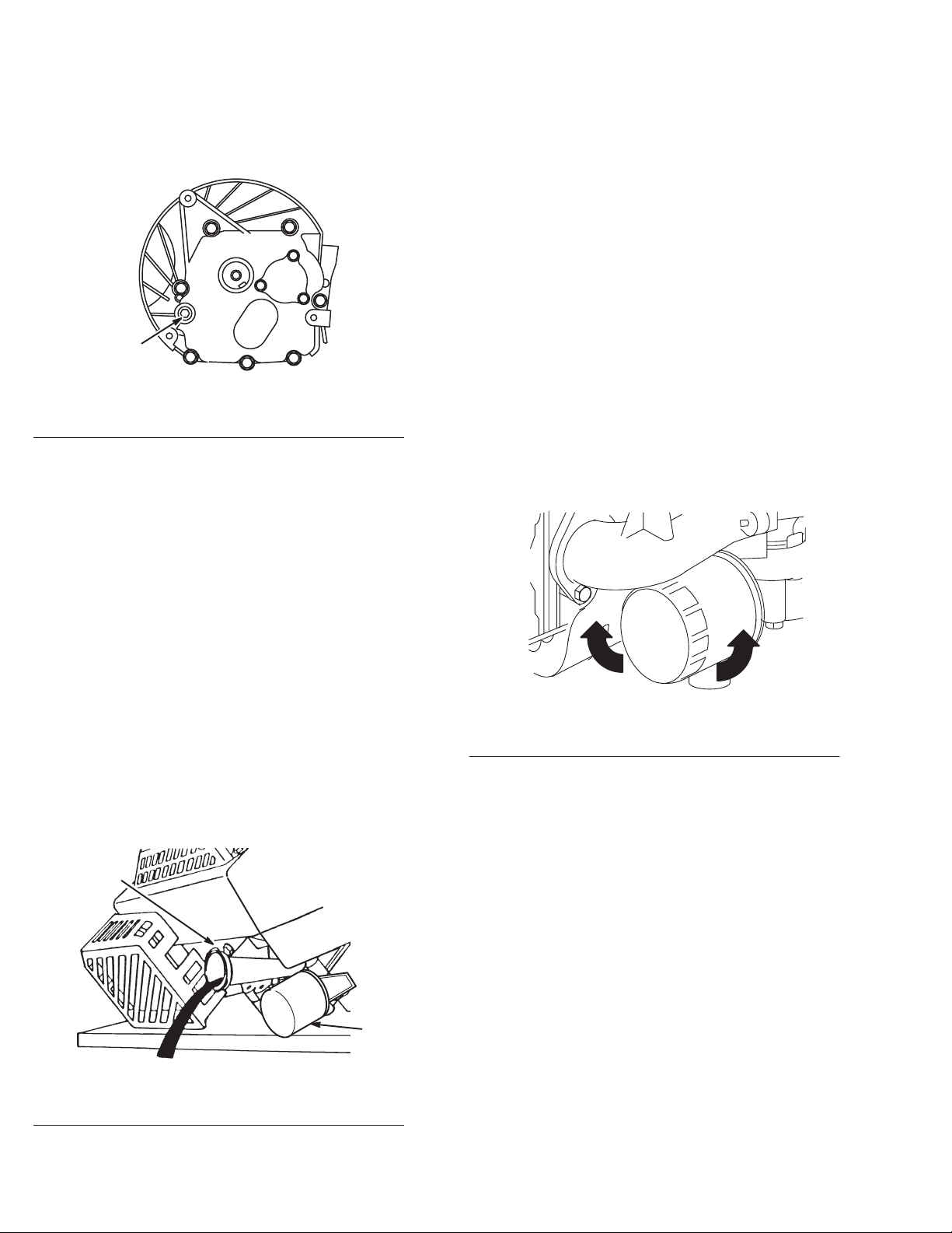
Cooling
Grass
particles, chaf
especially after prolonged service in very dusty conditions or
when cutting dry grass. Continued operation with a clogged
cooling system can cause severe overheating and possible
engine damage. Figures 5 and 6 show the areas to be cleaned.
7
System
f, or dirt can clog the air cooling system,
General Information
Page 10
This
should be a regular maintenance operation, performed
yearly or every 100 hours, whichever comes first and more
often when dust or when airborne debris is present.
1
Fig. 5
– Static Screen
1. Static
screen
1 2
1 2
Fig. 7
– Remove Spark Plug W
1. Primer 2. Spark
ire Prior to Service
m–3662
plug wire
Fig. 6 – Cylinder Fins and Ducting
1. Ducting 2. Cylinder
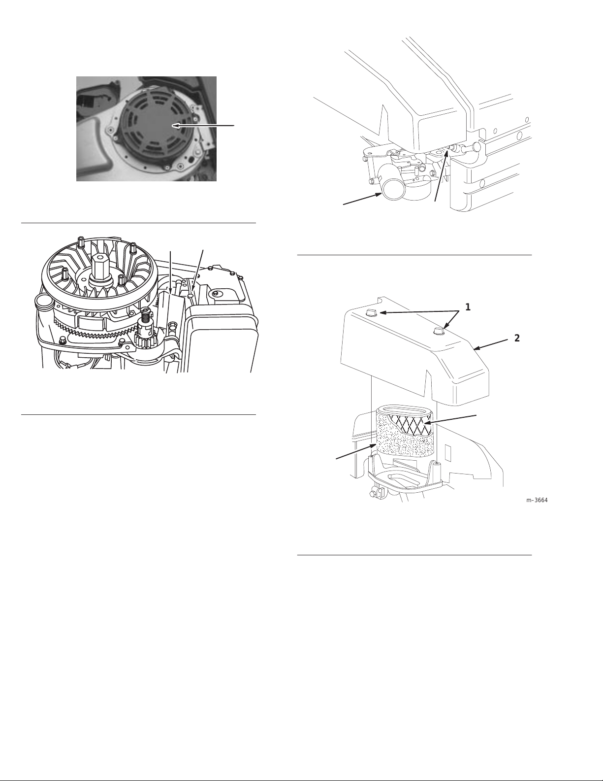
Air
Cleaner – General
A
properly serviced air cleaner protects internal parts of the
engine from dust particles in the air
. If air cleaner instructions
fins
are not carefully followed, dirt and dust which should be
collected in the air cleaner will be drawn into the engine and
become a part of the oil film, which is very detrimental to
engine life; dirt in the oil forms an abrasive mixture which
wears moving parts instead of protecting them.
2. Loosen
(Fig. 8).
3
1. Knob
2. Cover
two (2) knobs securing air cleaner cover to engine
1
2
4
m–3664
Fig. 8
– Air Cleaner Service
3. Foam
4.
pre–cleaner
Paper cartridge
Air
Cleaner Service
Normally,
clean the air cleaner pre–cleaner after every
25 operating hours or every season. Clean or replace the paper
cartridge after every 100 hours or every season. More frequent
cleaning is required when mower is operated in dusty or dirty
conditions. Replace air cleaner parts, if very dirty
IMPORTANT
elements; extr
Note: T
: Do not operate engine without air filter
eme engine wear or damage will occur
ipping mower on wrong side to service underside of
.
.
mower may cause damage to air filters.
1.
Stop engine and pull wire of
General
Information
f spark plug (Fig. 7).
3. Lift
cover of
Carefully remove pre–cleaner
4.
f. Clean cover thoroughly
. If pre–cleaner is dirty
.
carefully wash it in a solution of liquid soap and warm
water
. Rinse in clear water
. Allow to dry thoroughly before
using.
5.
If paper cartridge is dirty
it
gently
on a flat surface. If very dirty
IMPORTANT
Do not use pr
6.
Reinstall pre–cleaner over paper cartridge. Reinstall air
: Do not oil pr
essurized air to clean paper cartridge.
, clean the paper filter by tapping
, replace cartridge.
e–cleaner or paper cartridge.
cleaner cover and tighten securely in place with two (2)
knobs.
8
,
GTS 200
Page 11

Tune-Up
By
performing the following steps you will either be sure that the engine is functioning properly or will know what repairs should
be made.
These steps are also covered in the Overhaul Procedure and will normally be performed as a part of complete overhaul.
Carbon deposits in combustion chamber should be removed every 100 to 300 hours of use (more often when run at steady loads),
or whenever cylinder head is removed.
Procedure
Step No.
1. Remove
2.
3.
4.
5.
6.
7.
8.
9.
10.
11.
12.
13.
14.
15.
16.
Check oil level and drain oil.
Remove blower housing, inspect rewind assembly
Clean cooling fins and entire engine.
Remove carburetor
necessary and assemble. Set initial adjustment.
Inspect intake elbow or carburetor spacer for damaged gaskets.
Check governor, linkage, and springs for damage, wear
Clean fuel tank and lines.
Remove flywheel. Check for oil seal leakage, both flywheel and PT
Check armature coil. Inspect all wires for breaks and/or damaged insulation. Be sure lead wires do not touch
flywheel. Check stop switch and lead(s).
Remove oil, debris, and nicks from flywheel and crankshaft tapers.
Install flywheel and set air gap. Check for spark with Briggs & Stratton T
Remove spark plug and cylinder head.
Inspect valves for seating.
Clean carbon from cylinder head and piston.
Replace gaskets and install cylinder head. Tighten to specified torque. Adjust valve clearance. Set spark plug
gap or replace plug if necessary
air cleaner
, check for proper servicing. Replace if damaged or dirty
.
, disassemble, and inspect for wear or damage. W
, also check adjustment.
.
ash in solvent. Replace parts as
O sides. Check flywheel key
ool #19051 or #19368 ignition tester
.
.
.
17.
18.
19.
20.
21.
GTS 200
Replace gaskets and install carburetor
Adjust remote control linkage and cable, if used, for correct operation.
Check muf
Replace oil and fuel.
Run engine and adjust carburetor mixture and engine T
fler for restrictions or damage.
op No Load RPM.
9
General
Information
Page 12

Overhaul
The
Overhaul Procedure which follows is intended to help you become accustomed to a systematic method of repairing T
GTS 200
operations are performed in the same sequence every time.
The Overhaul Procedure can also be used as an index. For information on how to perform most operations listed, refer to the
section number or operation.
Disassemble
Check
OHV engines. Naturally these steps could be rearranged in dif
compression
Procedure
ferent order but ef
Section
Compression 27
oro
ficiency is obtained when the repair
Beginning
Page
Drain oil – Remove oil filter (when equipped)
Air cleaner
Fuel line, tank assembly and brackets, carburetor and linkage, carburetor
intake manifold or spacer
Exhaust manifold, muf
Disassemble carburetor
Electric starter (12 V) Blower housing
Breather and valve cover
V
alves and springs, rocker arms, push rods, cylinder head and shields,
valve guides and seats
Rewind starter
Flywheel Ignition 14
Check crankshaft end play
Remove burrs from crankshaft extension
Crankcase cover or sump
Mechanical governor parts
Cam gear and tappets
Connecting rod and piston
fler Muffler 59
Lubrication 47
General Information
Carburetion 18
Carburetion 18
Electric Starter
Lubrication 47
Compression 27
Rewind Starter
Crankshaft and Camshaft
Crankshaft and Camshaft
Crankshaft and Camshaft
Governor 25
Crankshaft and Camshaft
Pistons, Rings, and Rods
38
33
53
53
53
53
49
5
Crankshaft
Inspection Section
Inspect carburetor choke, throttle shaft, and bushings for wear and
freedom of movement
Inspect and test ignition coil
Crankshaft – inspect and check
Oil pump – inspect and check, if so equipped
Cylinder – check bore, main bearing
Check piston, rings, connecting rod, and piston pin
General Information
10
Crankshaft and Camshaft
Carburetion 18
Ignition 14
Crankshaft and Camshaft
Lubrication 47
Cylinder and Bearings
Pistons, Rings, and Rods
53
Beginning
Page
53
56
49
GTS 200
Page 13

Beginning
Repairs Section
Clean/replace parts as required
Replace block or short block if cylinder is over allowable dimension Cylinder and Bearings
Replace valve guides – intake or exhaust, if required
Reface valves and seats and lap, if required
Replace ignition armature, if required
Replace throttle shaft bushings, if required
Repair carburetor
Replace rewind starter spring and rope (if so equipped)
Replace main bearings and seals, if required
Reassemble Section
Crankshaft
Piston, piston pin, connecting rod, and rings
T
appets, cam gear
Oil pump, if so equipped
Mechanical governor
Crankcase cover or sump
Breather Lubrication 47
Flywheel, starter cup, and fan
Ignition armature assembly
Adjust ignition armature to flywheel air gap
Check spark
Electric starter (12 V)
V
alves, valve stem seals, springs, retainers, rocker arms
Cylinder head and push rods
Adjust valve clearance
V
alve cover
Spark plug – adjust gap to .020”
Exhaust manifold, muf
Intake manifold
Carburetor and linkage and governor controls Governor Controls,
Check and adjust mechanical governor
Blower housing and rewind starter
Fuel filter
Clean/replace and assemble air cleaner
Fill crankcase with oil, fill with gas, start engine
Adjust carburetor
Set governor to obtain correct engine speed (remote controls)
Spray paint engine parts and apply decals
, tank, and line
flers Muffler 59
Compression 27
Compression 27
Ignition 14
Carburetion 18
Carburetion 18
Rewind Starter
Cylinder and Bearings
Crankshaft and Camshaft
Pistons, Rings, and Rods
Crankshaft and Camshaft
Lubrication 47
Governor 25
Crankshaft and Camshaft
Ignition 14
Ignition 14
Ignition 14
Ignition 14
Electric Starter
Compression 27
Compression 27
Compression 27
Compression 27
Ignition 14
Carburetion 18
Carburetor Linkage, and
Flywheel Brake
Governor 25
Ignition 14
Carburetion 18
General Information
General Information
Carburetion 18
Governor 25
Page
56
33
56
Beginning
Page
53
49
53
53
38
22
5
5
GTS 200
11
General Information
Page 14

Check-Up
Most
complaints concerning engine operation can be
classified as one or a combination of the following:
1. W
ill not start
2.
Hard starting
3.
Lack of power
4. Vibration
5. Overheating
6.
High oil consumption
Whe
n the c
aus
e o
f m
alfunctio
chec
k o
f th
e c
ompression
, p
check-up
i
n a m
atter o
determinin
possibl
e c
time. Th
models
subjec
e b
, w
t h
erforme
g the c
aus
asi
hil
eading.
f m
inutes. I
aus
e o
f futur
c c
heck-u
e any v
d i
n a s
e o
ariation
Check Compression
See
the section Compression for proper procedure.
If compression is poor
1.
Loose spark plug
2.
Loose cylinder head bolts
3.
Blown head gasket
4.
Burned valves, valve seats
5. Insuf
6. W
7. W
8. W
9.
ficient valve clearance
arped cylinder head or warped valve cover
arped or worn valve stems and guides
orn bore and/or rings
Broken connecting rod
Check Ignition (Using Engine Starter)
WARNING
n i
, i
gnition
ystemati
t i
s the q
f failure. Thi
e f
ailures
, w
p p
rocedur
, b
y m
, look for –
s n
ot readil
, and c
c m
uickes
hic
e i
odel
y a
arburetio
anner
, can u
t and s
s c
heck-u
h can b
s the same for all e
, will b
pparent
ures
t m
p will p
e c
orrecte
e s
how
n s
suall
n u
, p
erfor
m a
ystems. This
y b
e d
one
etho
d o
f
oin
t o
ut
d a
t t
he
ngine
nder the
If spark does not occur
1.
Shorted stop switch wire
2.
Shorted stop switch
3.
Ignition armature failure
4.
Improperly operating interlock system
Note:
If engine runs but misses during operation, a quick
check to determine if ignition is or is not at fault can be made
by inserting the spark tester between the ignition cable and the
spark plug. A spark miss will be readily seen. See the Ignition
section.
, look for –
Check Carburetion
Before
making a carburetion check, be sure the fuel tank has
an ample supply of fresh, clean gasoline. Be sure that the
shut-of
f valve is open and fuel flows freely through fuel line
and filter before starting engine. Inspect and adjust the needle
valve. Check to see that the choke closes completely
will not start, remove and inspect the spark plug.
If plug is wet, look for –
1.
Over choking
2.
Excessively rich fuel mixture
3. W
ater in fuel
4.
Inlet needle stuck open
5.
Clogged air cleaner
6.
Fouled spark plug
If plug is dry
1.
Leaking carburetor mounting gaskets
2.
Gummy or dirty carburetor
valve or fuel tank
3.
Inlet needle stuck shut
4.
Inoperative fuel pump (if so equipped)
A simple check to determine if the fuel is getting to the
combustion chamber through the carburetor is to remove the
spark plug and pour a small quantity of gasoline through the
spark plug hole. Replace the plug. If the engine fires a few
times and then stops, look for the same conditions as for a dry
plug.
, look for -
, fuel filter
, fuel lines, shut-of
. If engine
f
BE
SURE ther
which might be ignited by the spark and cause a
fir
e or explosion.
Attach a spark tester to spark plug wire and ground the other
end of the tester to the engine block. W
spark plug. Spin the flywheel with the engine starter
jumps the
ignition system is performing satisfactorily
Ignition for additional information.
General Information
e is no fuel or fuel vapor pr
.166”
(4.20mm)
tester gap, you can assume the
esent,
arning: Do not remove
. If spark
. See the section
Equipment
Affecting Engine
Operation
What
appears to be a problem with engine operation, such as
hard starting, vibration, etc., may be the fault of the mower
rather than the engine itself. Listed are the most common
ef
fects of equipment problems and what to look for as the
most common cause.
12
GTS 200
Page 15

Hard Starting, or Will Not Start
Power Loss
1. Check
2. Chec
remote control assembly for proper adjustment.
k i
gnitio
n s
ystem.
Vibration
1.
Cutter blade bent – Remove and replace.
2.
Cutter blade out of balance – Remove and balance.
3.
Crankshaft bent – Replace.
4. W
orn blade coupling – Replace if coupling allows blade to
shift, causing unbalance.
5.
Mounting bolts loose – T
6.
Mounting deck or plate cracked – Repair or replace.
7.
Damaged belts or pulleys.
ighten.
1. Grass
2.
3.
4.
cuttings build-up under deck.
No lubrication in transmission or gear box.
Dull blade.
Excessive drive belt tension may cause excess bearing
wear or seizure.
Noise
1.
BBC system problems (if so equipped).
2.
No lubricant in transmission or gear box.
3. W
orn drive belts.
4. W
orn bearings.
GTS 200
13
General
Information
Page 16
Ignition
Contents
Check Ignition14. . . . . . . . . . . . . . . . . . . . . . . . . . . . . . . . . . .
Check For Spark Miss14. . . . . . . . . . . . . . . . . . . . . . . . .
Spark Plug15. . . . . . . . . . . . . . . . . . . . . . . . . . . . . . . . . . . . . .
Spark Plug Maintenance15. . . . . . . . . . . . . . . . . . . . . . .
Remove Ignition Armature15. . . . . . . . . . . . . . . . . . . . .
Remove Flywheel15. . . . . . . . . . . . . . . . . . . . . . . . . . . . . . . .
Inspect Flywheel Key
and Crankshaft16. . . . . . . . . . . . . . . . . . . . . . . . . . . . . . . . .
Install Flywheel
Install Flywheel16. . . . . . . . . . . . . . . . . . . . . . . . . . . . . .
Install Ignition Armature16. . . . . . . . . . . . . . . . . . . . . . .
Adjust Ignition Armature Air Gap17. . . . . . . . . . . . . . .
Specifications 17
, Keyways, Flywheel,
. . . . . . . . . . . . . . . . . . . . . . . . . . . . . . . . . .
. . . . . . . . . . . . . . . . . . . . . . . . . . . . . . . . . . . .
16
1
Fig. 9
– Checking for Spark
1. Spark
plug wire
Check For Spark Miss
2.
Spark tester
Stratton T
#19368
2
, Briggs &
ool #19051 or
WARNING
T
O PREVENT accidental starting, the spark plug
wir
e must be r
gr
ounded, failur
injury.
emoved fr
e to do so can cause personal
om spark plug and
WARNING
DO NOT r
ignition. A fir
emove spark plug when checking
e or explosion may occur
.
WARNING
FL
YWHEEL KICKBACK can occur if the
flywheel key is shear
occur.
Check
1. Connect
2.
Operate starter and observe spark gap in tester
jumps tester gap, ignition is good.
Ignition
spark plug wire to Spark T
ed and bodily injury may
ester
, Fig. 9.
. If spark
1. Install
1. Spark
2.
2. Start
3.
Briggs & Stratton T
Tester
, in series with spark plug lead and spark plug,
Fig. 10.
1
Fig. 10 – Running Check
plug lead
Spark tester
Stratton T
#19368
If spark jumps tester gap regularly
problem is spark plug, compression, or fuel system.
, Briggs &
ool #19051 or
and run engine.
ool #19051 or #19368, Spark
2
3.
Spark plug
, but miss continues,
3
Note:
Note:
Ignition
Flywheel must rotate at 350 RPM, minimum.
Spark will be observed.
14
GTS 200
Page 17
Spark
The
Plug
recommended spark plug is:
Spark Plug Type Brand
Resistor Long Plug
Note:
In some areas, local law requires the use of a resistor
Champion
RC12YC
spark plug to suppress ignition signals. If an engine was
originally equipped with a resistor spark plug, be sure to use
the same type of spark plug for replacement.
Spark Plug Maintenance
Set
gap at .020” (0.51mm), Fig. 11. If electrodes are burned
away
, or porcelain is cracked or fouled, replace with a new
plug.
Note:
Do not use abrasive cleaning machines.
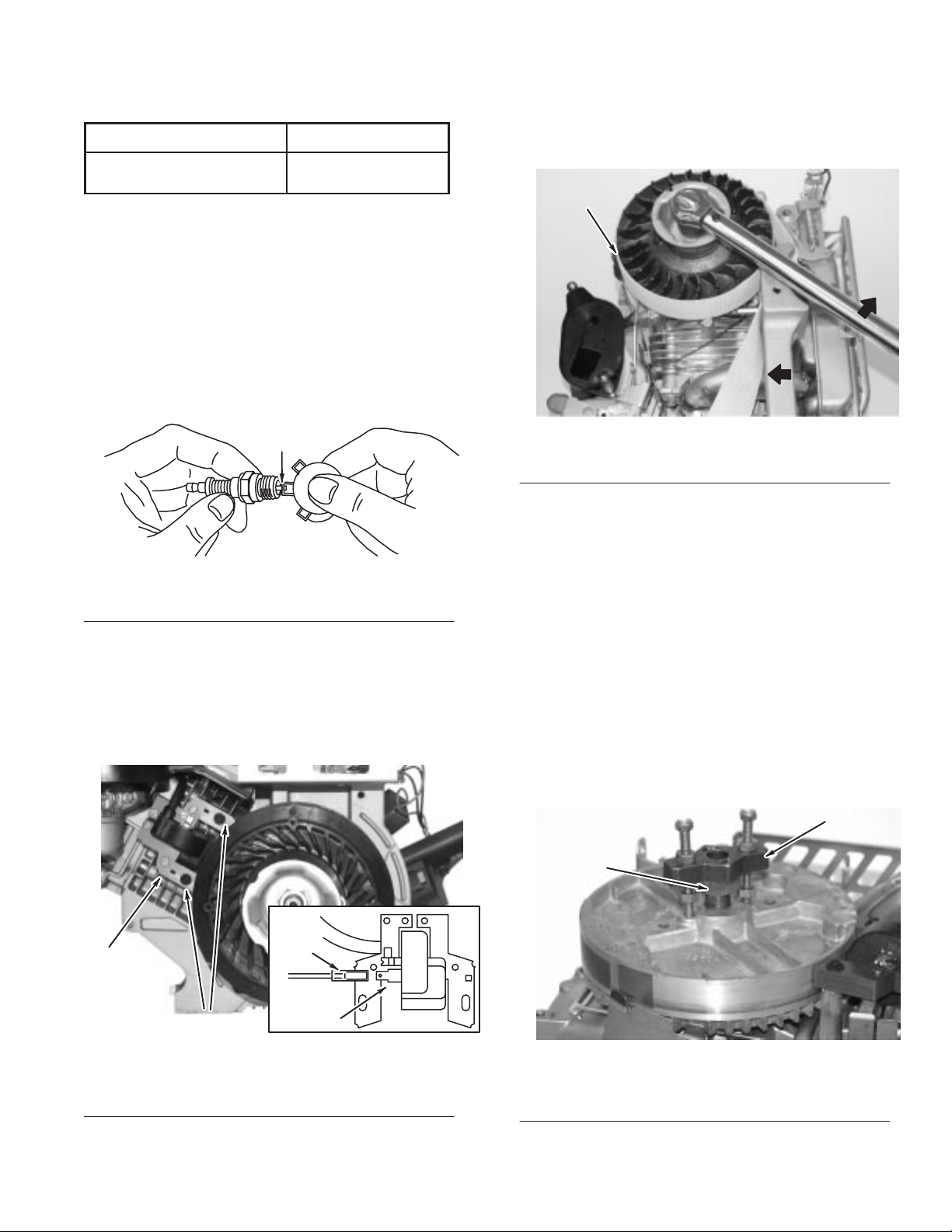
Remove
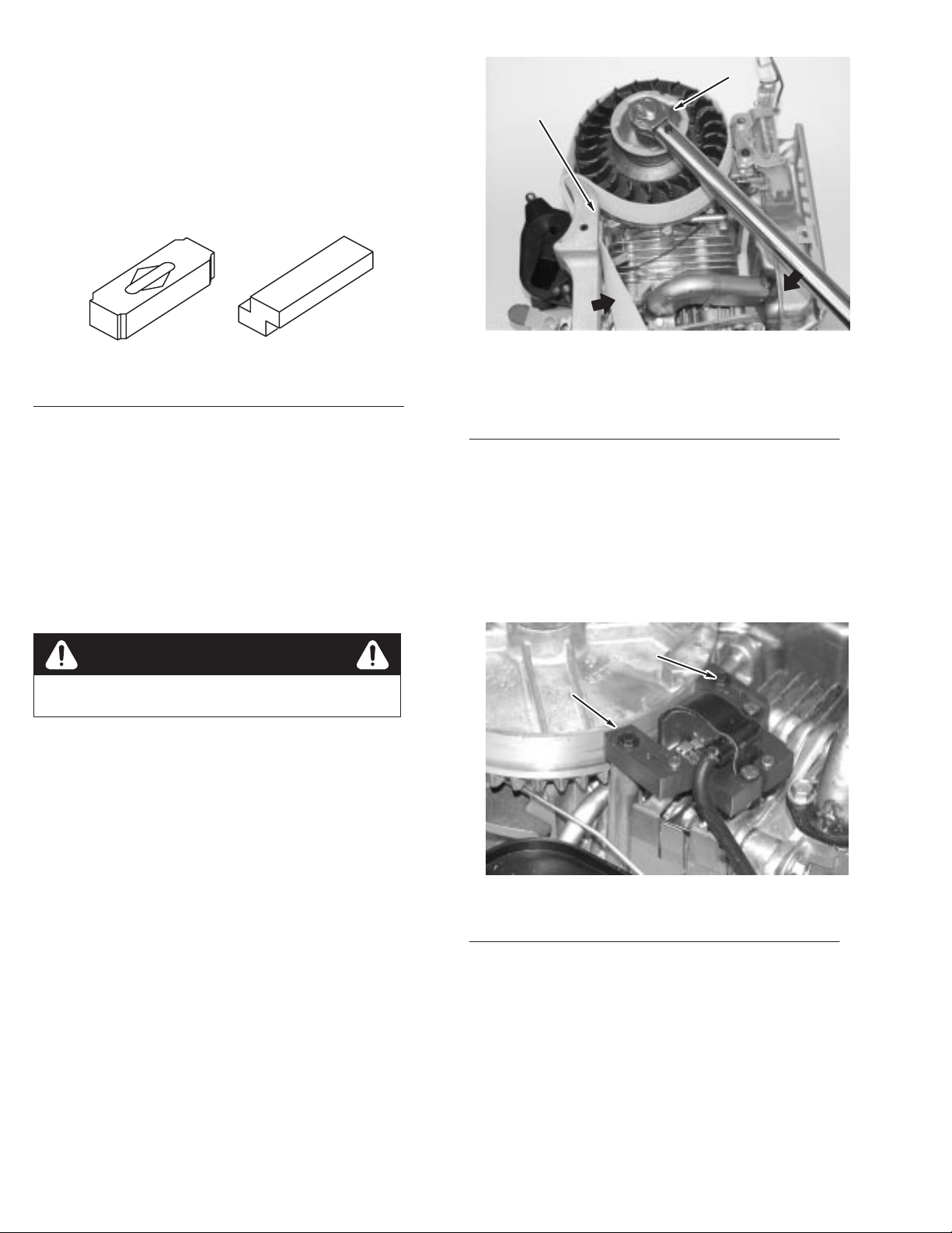
1. Remove
2.
Use flywheel holder to hold flywheel from turning,
Flywheel
blower housing.
Fig. 13.
1
1
1. .020”
Fig. 11
(0.51mm) wire gauge
– Adjusting Spark Plug Gap
Remove Ignition Armature
1. Remove
2.
Remove armature screws, disconnect stop wire, and lift of
armature, Fig. 12.
blower housing.
Fig. 13
1. Flywheel
3. Use
socket and breaker bar to remove flywheel nut.
Note:
Remove ignition armature before removing
– Removing Flywheel Nut
holder Briggs & Stratton T
ool #19372
flywheel.
4.
Thread flywheel nut onto crankshaft until top of nut is
flush with crankshaft threads or slightly 1.5mm (1/16”)
above end of threads.
5.
Attach flywheel puller
6. T
urn puller screws into flywheel puller holes until screws
.
bottom.
7. T
f
urn lower nuts down until flywheel puller body rests
firmly on flywheel nut.
8.
Then turn upper nuts down onto puller body
. T
urn both
nuts equally until flywheel pops loose, Fig. 14.
2
1
1
Fig. 12
1. Ignition
2. Screws
GTS 200
3
2
– Removing Ignition Armature
armature
Stop switch wire
3.
4. Terminal
4
1. Flywheel
15
Fig. 14
nut
– Removing Flywheel
2.
Briggs & Stratton T
#19069 flywheel puller
ool
Ignition
Page 18
Inspect
Flywheel Key
, Keyways,
Flywheel, and Crankshaft
Inspect
flywheel key for partial or complete shearing. If
sheared, replace, Fig. 15. Flywheel should be inspected for
cracks, burrs on taper or keyway, and distortion of keyway
Check taper of crankshaft for burrs, rust, oil, or other damage.
Check cooling fan or flywheel for broken fins. If parts are
damaged, replace with new parts.
1 2
.
2
1
Fig. 15 – Inspect Flywheel Key
1. OK 2. Replace
Install
Flywheel
Install Flywheel
1. Clean
2.
flywheel taper and crankshaft taper of all grease, oil
and dirt.
Slide flywheel onto crankshaft and line up both keyways.
Insert flywheel key into both keyways.
Note:
DO NOT use a steel key under any circumstances.
WARNING
DO NOT use impact wr
3.
Install starter cup, cooling fan, and flywheel nut or screw
4.
Use flywheel holder to hold flywheel from turning,
Fig. 16.
enches to install flywheel.
Fig. 16 – Torquing Flywheel
1. Briggs
& Stratton T
#19321,
flywheel holder or
Tool
# 19372 flywheel
strap wrench
ool
2. Cup
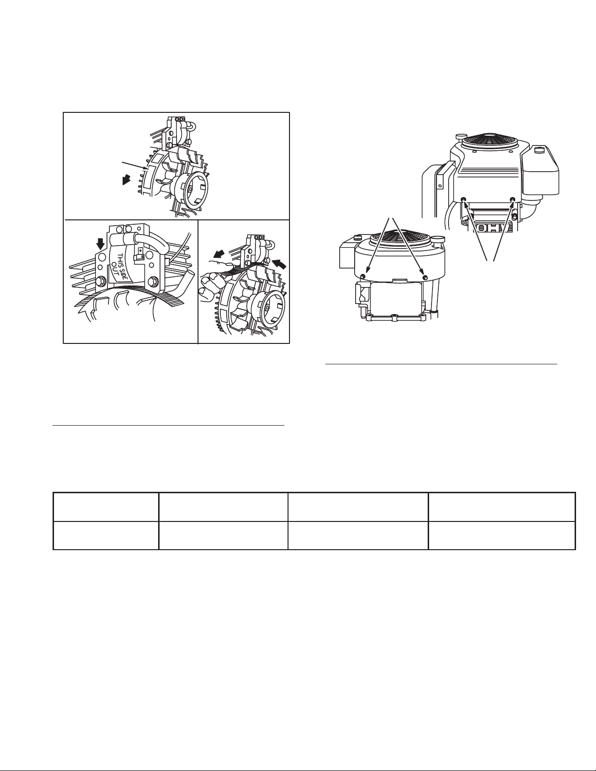
Install Ignition Armature
1. Install
2. T
3.
.
stop switch wire on armature, Fig. 12, Page 15.
urn flywheel so magnet is away from armature.
Install armature and mounting screws, Fig. 17.
Note:
Mounting holes in armature are slotted.
2
1
5.
Install flywheel nut or screw
Use socket and torque wrench to tighten flywheel nut or
6.
screw.
7. T
orque as listed in T
Ignition
able No. 1, Page 17.
.
16
Fig. 17
1. Ignition
4. Push
armature
armature away from flywheel as far as possible and
tighten one screw to hold armature in place.
– Installing Armature
2. T
ighten one screw
GTS 200
Page 19
Adjust Ignition Armature Air Gap
1. Rotate
2.
flywheel until magnet is under armature
laminations.
Place thickness gauge, T
able No. 1, Page 17, between
magnet and armature laminations, Fig. 18.
1
2
3
5
3. See T
able No. 1, Page 17 for armature air gap. Loosen
mounting screw so magnet will pull armature down against
thickness gauge.
4. T
orque both mounting screws to 25 in. lbs.
(3.0Nm)
Rotate
flywheel to remove thickness gauge.
5.
Install outer blower housing and screws and torque screws
to 85 in. lbs., (10.0Nm),Fig. 19.
1
4
1
Fig. 18
1. Magnet
2. Turn
magnet away from
armature
Armature down; gauge
3.
stock in place
– Adjusting Armature Air Gap
Specifications
Armature
.006” – .012”
(0.15 – 0.30mm)
Air Gap
4. Turn
5.
Roll out gauge
Flywheel Puller
Briggs & Stratton T
19069 19372
ool #
Fig. 19
1. Torque
Table No. 1
Flywheel Holder
Briggs & Stratton T
– Installing Outer Blower Housing
screws to 85 in. lbs.
ool #
Flywheel Nut Torque
60 ft. lbs.
(81.0Nm)
GTS 200
17
Ignition
Page 20

Carburetion
Contents
Service
These carburetor
non-adjustabl
Carburetor W
e idle m
s have a f
ixture
ixe
d high s
, Fig.
21.
albro LMS
pee
d main jet w
ith
Carburetor
Service Carburetor W
Carburetor
Identification18. . . . . . . . . . . . . . . . . . . . . . . . . . .
albro LMS18. . . . . . . . . . . . . . . . . . . . .
Remove Air Cleaner18. . . . . . . . . . . . . . . . . . . . . . . . . .
Remove Carburetor19. . . . . . . . . . . . . . . . . . . . . . . . . . .
Disassemble Carburetor19. . . . . . . . . . . . . . . . . . . . . . .
Carburetor Cleaning Recommendations20. . . . . . . . . . .
Assemble Carburetor20. . . . . . . . . . . . . . . . . . . . . . . . . .
Install W
Install Throttle Shaft20. . . . . . . . . . . . . . . . . . . . . .
Install Inlet Needle Seat20. . . . . . . . . . . . . . . . . . .
Install Inlet Needle and Float20. . . . . . . . . . . . . . .
High Altitude Compensation21. . . . . . . . . . . . . . .
Install Carburetor21. . . . . . . . . . . . . . . . . . . . . . . . . . . .
Install Air Cleaner21. . . . . . . . . . . . . . . . . . . . . . . . . . . .
elch Plug20. . . . . . . . . . . . . . . . . . . . . . . .
Identification
3
2
111
1. Float
2.
Choke plate
3.
Choke lever
Fig. 21
bowl
– Fixed Main Jet Carburetor
Remove Air Cleaner
1. Remove
air cleaner element, Fig. 22.
air cleaner screws and air cleaner cover
4.
Throttle lever
5.
Idle speed screw
6.
I.D. number
4
5
6
. Remove
Fig. 20
– Primer Carburetor
WARNING
NEVER STAR
removed, fir
T o
e can r
r o
esult.
perat
e e
ngin
e with air c
leaner
CAUTION
T
O PREVENT accidental starting when servicing
engine or equipment, always remove spark plug
wir
e from spark plug and pr
contacting spark plug.
event wir
e fr
om
2. Then remov
o
n c
arburetor
3
5
Fig. 22
1. 2 screws
2. Cover
3. Pre-cleaner
e t
wo (2
) s
crew
s h
oldin
g air c
, Fig.
22.
– Removing Air Cleaner
4. Cartridge
5. Base
leaner/primer base
1
2
4
m–3664
Carburetion
18
GTS 200
Page 21

Remove Carburetor
1. Move
fuel line clamp and disconnect fuel line from
carburetor.
1
2
WARNING
CLOSE FUEL valve or plug fuel line to pr
fuel spillage. Do not use a scr
ew to plug fuel line
as this damages interior of hose.
2.
Remove carburetor and rotate carburetor until governor
link is free.
3.
On current production engines, the control bracket is held
on with three (3) screws, of which two (2) were removed
to remove the carburetor
, Fig. 23. On early production
engines, only two (2) screws held both carburetor and
control bracket. Reinstall both screws to retain control
bracket until carburetor is reinstalled.
Note:
Replace air cleaner gaskets and mounting gaskets
whenever carburetor is removed for service.
56
1
event
3
3
Fig. 24
– Removing Main Jet, Float Hinge Pin
and Inlet Needle
1. Float
2. Float
4. Remove
5.
6.
7.
8.
hinge pin
idle speed screw with spring, when used.
Rotate throttle shaft to closed position and remove throttle
plate screw
.
Remove throttle plate and throttle shaft with foam seal.
Grasp choke plate and remove from choke shaft.
Remove choke shaft and felt or foam washer
3.
Inlet needle
, when used.
2
1
Fig. 23
1. Mounting screw
2. Carburetor
Carburetor control bracket
3.
4. Gasket
4. Remove
two (2) carburetor mounting screws.
– Removing Carburetor
5.
6.
1
Current style, mounting
hole
Early style
Disassemble Carburetor
1. Remove
2.
Remove float bowl and bowl gasket from carburetor
Remove float hinge pin, float and inlet needle, Fig. 24.
3.
bowl nut (with fixed main jet) and fiber washer
9. W
ith a modified 5/16 inch (3.9mm) pin punch, remove
welch plug(s) from carburetor body
Note:
A convenient way to remove inlet needle seat is with a
, Fig. 25.
#5 crochet hook.
4
1
2
3
4
5
6
.
.
1. Choke
2.
Idle speed screw
3.
Throttle shaft
Fig. 25
plate and shaft
– Removing W
4. W
5.
6.
elch Plug
elch plug
5/32” punch
Throttle plate screw
GTS 200
19
Carburetion
Page 22

Carburetor Cleaning Recommendations
1. Disassemble
Remove all old gaskets, seals and sealing material.
2.
3.
Use commercial carburetor cleaning solvents to clean
carburetor parts and body
4.
When cleaning non-metallic parts (plastic, nylon,
Minlon
cleaner bath more than 15 minutes.
Note:
Parts containing rubber
pump diaphragms should never be placed in commercial
carburetor cleaner bath.
5.
Use only compressed air (blowing in both directions) to
clean out all openings and passages.
Note:
Do not
metering holes or passages.
carburetor
.
.
, etc.), do not leave in commercial carburetor
, such as seals, “O” rings or
use wires, drills or any other devices to clean out
3.
Lay throttle plate on shaft with numbers facing out and
install screw
, Fig. 27. Use a new patchlock screw
Loctite to secure screw in place.
2
1
3
Fig. 27 – Installing Throttle Shaft
1. Numbers
2. Throttle
shaft
3.
Foam washer
, or use
Assemble Carburetor
Install Welch Plug
1. Install
1. Welch
2. Press
3.
Install Throttle Shaft
1. Install
2. T
welch plug(s) with pin punch slightly smaller than
outside diameter of plug, Fig. 26.
1
Fig. 26 – Installing W
plug
elch Plug
2.
Pin punch
in until plug is flat. Do not cave in plug.
After plug is installed, seal outside edge of plug with
fingernail polish or non-hardening sealant.
throttle shaft and foam washer
.
urn shaft until flat is facing out.
Install
Inlet Needle Seat
Install
inlet needle seat with groove down using Briggs &
Stratton T
ool #19057, Bushing Driver
, until seated, Fig. 28.
1
2
2
Fig. 28 – Installing Inlet Needle Seat
1. Bushing
#19057
driver tool
2. Groove
Install Inlet Needle and Float
1. Install
2.
inlet needle on float and install assembly on
carburetor body
.
Insert float hinge pin and center pin between float pin
bosses. Float height is non-adjustable.
3.
Install rubber gasket on carburetor and lay float bowl on
body.
Carburetion
20
GTS 200
Page 23

4.
Place fiber washer over main jet and install main jet.
T
orque nut to 50 in. lbs. (6.0Nm), Fig. 29.
2
1
3
Fig. 29 – Installing Float, Hinge Pin and
Inlet Needle
1. Float
2. Hinge
pin
3.
Inlet needle
High Altitude Compensation
Note:
If engine is operated at high altitudes, performance may
decrease. If poor performance is experienced refer to the
proper T
oro parts manual for replacement high altitude main
jet.
56
1
Fig. 31
1. Mounting screw
2. Carburetor
3.
Carburetor control bracket
4. Gasket
– Installing Carburetor
Install Air Cleaner
1. Install breather tub
bas
e with new g
2.
Install air c
carburetor.
e on air c
aske
leaner primer bas
2
leaner primer bas
t o
n c
arbureto
3
1
4
1
Current style, mounting
5.
hole
6.
Early style
e and p
osition
r m
ountin
g s
urface.
e with two (2) screws into
Install Carburetor
1. Hook
2. Place
3.
4.
governor link into grommet on throttle lever from
the top, Fig. 30.
Fig. 30
– Install Carburetor
new intake gasket on throttle side of carburetor
Fig. 31.
Using carburetor mounting screws to align parts, place
carburetor on control bracket, Fig. 31.
Install carburetor assembly with two (2) mounting screws
torquing screws to 80 in. lbs. (10.0Nm), Fig. 31.
orque two (2) carburetor mounting screws to 30 in. lbs.
3. T
(3.0Nm), Fig. 32.
1
2
4
3
5
m–3664
Fig. 32
1. 2 screws
,
2. Cover
3. Pre-cleaner
4. Install
5.
Install air cleaner cover and two (2) screws, tighten screw
– Installing Intake Elbow Assembly
4. Cartridge
5. Base
air cleaner cartridge and pre-cleaner, Fig. 32.
farthest from spark plug first.
GTS 200
21
Carburetion
Page 24
Governor
Controls,
Carburetor Linkage,
and Flywheel Brake
Contents
3
2
1
Remote
Flywheel Brake22. . . . . . . . . . . . . . . . . . . . . . . . . . . . . . . . . .
Governor Adjustments24. . . . . . . . . . . . . . . . . . . . . . . . . . . . .
Governor and Carburetor Linkages24. . . . . . . . . . . . . . . . . . .
Remote
Governor Controls22. . . . . . . . . . . . . . . . . . . . . . . . .
Remote Control W
Speed Regulation22. . . . . . . . . . . . . . . . . . . . . . . . . . . . .
Adjust Remote Controls22. . . . . . . . . . . . . . . . . . . . . . .
Operation 22
Remove Flywheel Brake23. . . . . . . . . . . . . . . . . . . . . . .
Assemble Flywheel Brake23. . . . . . . . . . . . . . . . . . . . . .
Brake Adjustment24. . . . . . . . . . . . . . . . . . . . . . . . . . . .
. . . . . . . . . . . . . . . . . . . . . . . . . . . . . . . . . . .
ire Travel 22
. . . . . . . . . . . . . . . . . . . .
Governor Controls
Remote Control Wire Travel
In
order to make proper remote control adjustments, the travel
of the remote control wire must be not less than 1–3/8”
(35mm) with controls mounted in equipment, Fig. 33.
1
2
Fig. 34 – Speed Regulation
(air cleaner removed for clarity)
1. Governor
2.
Governor link
spring
3.
Remote control cable
Adjust Remote Controls
1. Loosen
2.
3.
casing clamp screw
Move equipment throttle lever to fast position.
Move casing in direction of arrow (Fig. 35) until casing
stops moving.
.
Fig. 33
1. 2–1/8”
Remote
or decreasing tension on governor spring to obtain desired
engine speed. Remote controls will provide governor control
at all positions.
(54mm) minimum
governor controls change engine speed by increasing
– Control W
ire T
ravel
2.
1–3/8” (35mm) minimum
travel
Speed Regulation
When
remote control is moved toward FAST position,
governor control rotates and increases tension of governor
spring on governor lever
and valve on carburetor toward wide open position, Fig. 34.
. Governor link moves throttle lever
2
1
Fig. 35
1. Casing
4. Tighten
– Adjusting Remote Controls
clamp screw
casing clamp screw
2. Casing
.
Flywheel Brake
Operation
The
flywheel brake is part of the safety control system
required for this engine. The flywheel brake
engine within three seconds, while running at
position, when the operator releases the equipment safety
control.
MUST
FAST
stop the
speed
m–3638
Governor
and Flywheel Brake
Controls, Carburetor Linkage,
22
GTS 200
Page 25

Remove Flywheel Brake
1. Disconnect
2.
Remove static guard and fuel tank, Fig. 36.
1
spark plug lead from spark plug.
7.
Remove two screws from brake bracket and remove
bracket, Fig. 38.
1
8
2
3
2
Fig. 36
1. Static
2.
3. Remove
4.
– Removing Static Guard and Fuel T
guard
Fuel tank
3. Screw
dipstick and oil fill tube, Fig. 37.
Remove blower housing and rewind starter
3
2
1
3
2
ank
, Fig. 37.
1
6
7
5
1. Stop
2. Screw
3. Anchor
4.
switch wire
Brake bracket
Fig. 38
– Removing Brake Bracket
5.
Starter interlock switch
wires
Brake spring
6.
7.
Brake lever
8.
Brake pad
Inspect Flywheel Brake and Switches
1. Inspect
2. T
brake lining on brake lever
. Replace brake
assembly if lining is less than .090” (2.28mm) thick.
est stop switch as described in the section General
Information, stop switch – remote control.
3
4
4
Fig. 37
– Removing Dipstick and Oil Fill T
ube,
Blower Housing and Rewind Starter
1. Screw
2. Blower
5. Disconnect
6.
housing and
rewind starter
spring from brake anchor
Disconnect stop switch wire from stop switch. If engine is
3. Dipstick screw
4.
Dipstick and oil fill tube
.
equipped with electric starter, disconnect both wires from
starter interlock switch.
3. T
est electric starter interlock switch as described in the
section Electric Starter
, Check Interlock Switch.
Assemble Flywheel Brake
1. Install
2.
3.
4.
5.
brake assembly on crankcase and torque mounting
screws to 40 in. lbs. (5.0Nm) Fig. 38.
Install stop switch wire and bend end of wire 90°. Install
interlock switch wires on interlock switch, if used, Fig. 38.
Install blower housing as described on page 37, “Install
Blower Housing and Rewind Starter
.”
Install dipstick tube and dipstick.
Install fuel tank and static guard.
GTS 200
23
Governor
Controls, Carburetor Linkage,
and Flywheel Brake
Page 26

Brake Adjustment
WARNING
TO
PREVENT accidental starting, the spark plug
wir
e must be r
gr
ounded, after r
can cause personal injury
1.
Using a torque wrench and socket to fit flywheel nut, turn
flywheel clockwise with brake engaged. While turning at a
steady rate, torque reading should be 30 in. lbs. (3.0Nm) or
higher.
2.
If reading is low
brake lever and pad if pad thickness is less than .090”
(2.28mm).
3.
If brake pad thickness is acceptable, adjust control cable
casing anchor to position pad closer to flywheel when
handle control bail is in RUN position.
4.
Replace brake assembly if correct adjustment cannot be
made.
emoved fr
emoving boot. Failur
, check thickness of brake pad. Replace
om spark plug and
e to do so
.
Governor
and Carburetor
Linkages
Figures 40 and 41 show governor and carburetor linkages.
1
Fig. 40 – Linkages
1. Governor
link
Governor
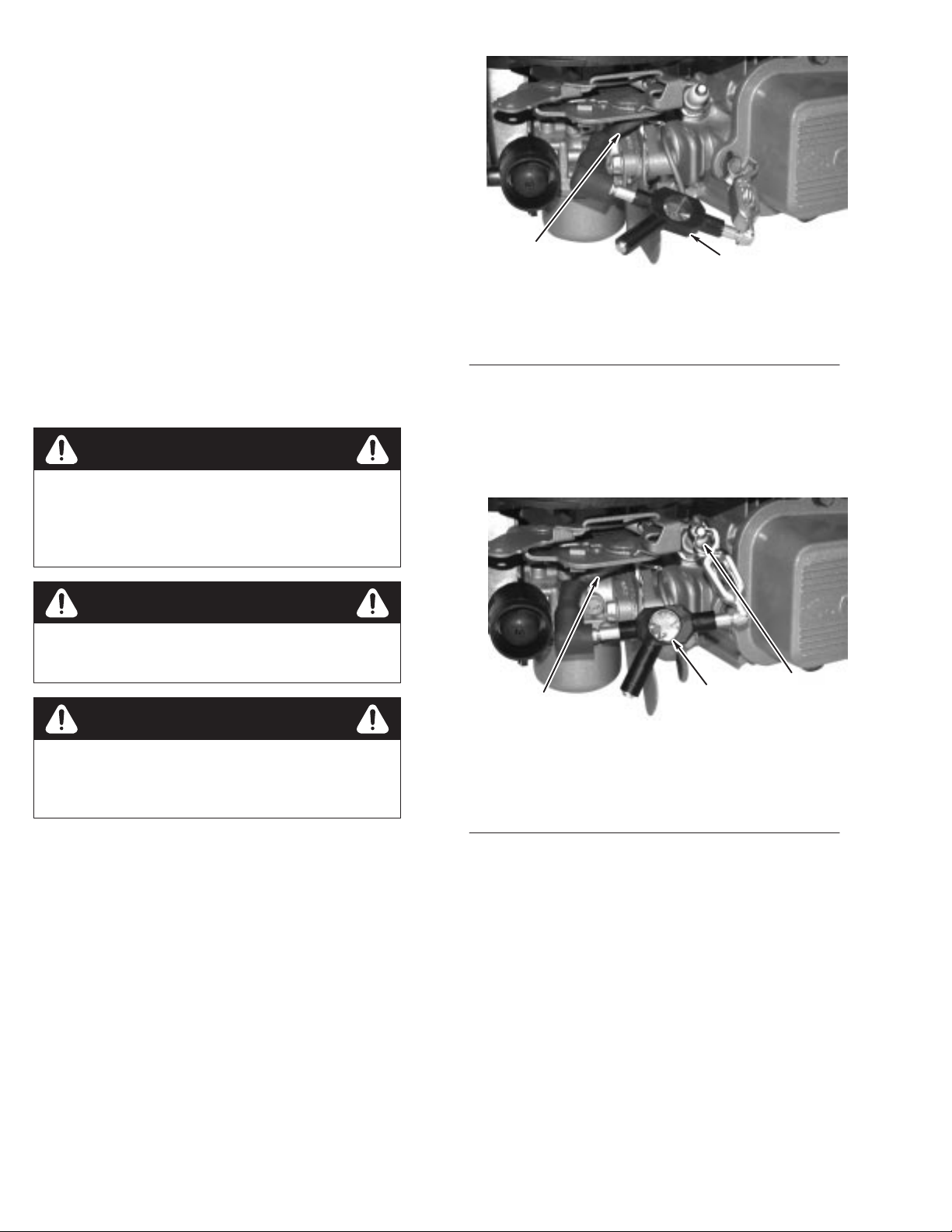
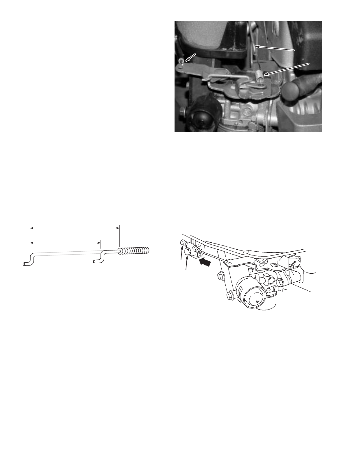
To
remove slack from the governor linkage:
1.
Slightly loosen the governor nut, Fig. 39.
Fig. 39 – Adjusting Governor Linkage
1. Governor
2.
Governor lever
2. Turn
the governor crank to the right (clockwise) until it
stops.
Adjustments
1
lever nut
3
3.
Governor crank
2
2
Fig. 41 – Linkages
(air cleaner removed for clarity)
1. Governor
spring
2.
Remote control cable
1
Rotate the governor lever to the right until it stops. Hold
3.
and tighten the governor lever nut.
T
o adjust top no load RPM, see page 26.
Refer to page 26 for specific procedures for governor
adjustments.
Governor
and Flywheel Brake
Controls, Carburetor Linkage,
24
GTS 200
Page 27

Governor
Contents
General
Governed RPM Limits25. . . . . . . . . . . . . . . . . . . . . . . . . . . . .
Mechanical Governor25. . . . . . . . . . . . . . . . . . . . . . . . . . . . . .
General
The
of the counterweights, which are operated by centrifugal
force, tends to close the throttle. The engine speed at which
these two forces balance is called the governed speed. The
governed speed can be varied by changing governor spring
tension or governor spring, Fig. 42.
Information25. . . . . . . . . . . . . . . . . . . . . . . . . . . . . . .
Disassemble 25
Inspect Governor26. . . . . . . . . . . . . . . . . . . . . . . . . . . . .
Assemble Governor Crank26. . . . . . . . . . . . . . . . . . . . .
Install Crankcase Cover or Sump26. . . . . . . . . . . . . . . .
Adjust T
Seal Protectors26. . . . . . . . . . . . . . . . . . . . . . . . . . . . . . .
. . . . . . . . . . . . . . . . . . . . . . . . . . . . . . . . .
op No Load RPM26. . . . . . . . . . . . . . . . . . . . .
Information
governor spring tends to pull the throttle open. The force
completely assembled machine. The RPM should be measured
with the mower on a hard surface to eliminate cutting load on
the blade.
If a governor spring must be replaced, consult the appropriate
T
oro Illustrated Parts List.
CAUTION
AFTER A new governor spring is installed, check
engine top no load speed.
Run engine at half throttle to allow the engine to reach normal
operating temperature before measuring speed with a
tachometer.
oro rotary mowers should be set to run at 3,000 RPM 150,
T
which will produce blade tip speeds of 19,000 feet per minute.
If a service replacement engine is used, check the top no load
speed with the engine operating on a completely assembled
mower
. If necessary
top no load speed limit device, so the engine will not exceed
the recommended speed. See page 26 for adjustment
procedure for mechanical governor
, change the governor spring or adjust the
.
Fig. 42
(blower housing removed)
1. Governor
spring
Governed
To
comply with specified top no-load speed limits, engines
use either calibrated governor springs or an adjustable top no
load speed. Calibrated springs or an adjustable top no load
speed limit will allow no more than a desired top governed
speed when the engine is operated on a rigid test stand.
However
engine speeds. Therefore, the top no load speed should be
checked with a tachometer when the engine is operated on a
, the design of the cutter blade, deck, etc., can af
– Governor Spring
RPM Limits
fect
Mechanical
The
mechanical governor used is illustrated in Fig. 43, and is
part of the oil slinger assembly
mounted in the cylinder assembly
1
2
1
1. Governor
2.
Governor weight pins
cup
Governor
4
Fig. 43
. The governor crank is
.
– Governor
3.
Governor gear and oil
slinger
Governor crank
4.
3
Disassemble
1. Before
2.
governor can be serviced, drain oil from engine and
remove crankcase sump, page 53.
Loosen governor lever bolt and nut, Fig. 44.
GTS 200
25
Governor
Page 28

3.
2
1
Install crankcase cover or sump screws and torque screws
in order of numbers cast on outside surface of sump to
1
10 in. lbs. (12.0Nm), Fig. 45.
Note: Scre
sealant. I
sealan
w a
f s
ealan
t such a
t p
osition fou
t i
s m
s P
ermatex2
r was f
issing
, coat with a n
, o
r e
actor
y c
quivalent.
oate
d w
ith
on-hardening
4
4.
5.
Governor crank
Push nut
Fig. 44
1. Governor
2.
Governor link
3.
Governor lever
3. Slide
lever of
5
– Removing Governor Lever
lever nut
f governor crank and disconnect from
governor link.
4.
Remove push nut and washer from governor crank,
remove burrs from governor crank, and remove crank from
inside cylinder
, Fig. 44.
Inspect Governor
1. Check governor gea
governo
chippe
2.
Replace governor gear assembly if damaged.
r w
d o
r damage
eigh
t p
ins
d t
r and oil s
, worn o
eet
h and p
linge
r a
r damage
addle
ssembly fo
d g
overno
s o
n oil s
r w
r cup, a
linger.
3
orn
nd
1
1. Screw
Fig. 45 – T
must have sealant
orque Sequence
Adjust Top No Load RPM
1. Start
2.
3.
and run engine for approximately 5 minutes to allow
it to reach operating temperature.
Place throttle in fast position.
Start engine and measure RPM using T
T
op No Load RPM by bending governor tang, Fig. 46.
achometer
Finger pressure will be sufficient to bend tang.
Note:
RPM 3000 150.
. Adjust
Assemble Governor Crank
1. Install
2.
3. T
governor crank from inside cylinder
. Slide washer
(when used) onto governor crank and install new push nut
on governor crank.
Slide governor lever onto governor crank and tighten bolt
and nut on lever until governor crank turns with a slight
resistance.
urn crank until crank end contacts governor cup on
governor gear or oil slinger
, Fig. 44.
Install Crankcase Cover or Sump
1. Install
2.
new crankcase cover or sump gasket(s) of same
thickness as originally removed on cylinder
Place Seal Protector
, Briggs & Stratton Tool #19334 or
.
#19356, BROWN, in seal of sump and slide sump down
over crankshaft until sump seats.
Note: I
t may b
e n
ecessar
y t
o rotat
e c
o get oil pump t
t
vertica
l c
rankshaf
o e
t e
ngag
e oil pump d
ngines.
rankshaf
riv
e slot i
t and cam g
n cam g
ear
ear on
3
Fig. 46 – Adjusting Top No Load RPM
(air cleaner cover removed for clarity)
1. Decrease
2. Increase
3. Bend
Seal Protectors
Briggs
Color
Crankshaft
& Stratton T
ool # .
. . .
. . . . . . . . . . . . . . . . . . . . . .
Journal Size. . . .
1
2
tang
19334/5
Brown
1.062”
(26.97mm)
Governor
26
GTS 200
Page 29

Compression
Contents
Test
Compression27. . . . . . . . . . . . . . . . . . . . . . . . . . . . . . . . .
Remove Cylinder Head28. . . . . . . . . . . . . . . . . . . . . . . . . . . .
Prepare Cylinder Head for Removal28. . . . . . . . . . . . . .
Remove Rocker Cover28. . . . . . . . . . . . . . . . . . . . . . . .
Remove Cylinder Head28. . . . . . . . . . . . . . . . . . . . . . . .
Remove V
Inspect V
V
alve Service29. . . . . . . . . . . . . . . . . . . . . . . . . . . . . . . . . . . .
Reface V
Assemble Cylinder Head29. . . . . . . . . . . . . . . . . . . . . . . . . . .
Install Cylinder Head Plate and
Rocker Arm Studs29. . . . . . . . . . . . . . . . . . . . . . . . . .
Install V
Install V
Install Cylinder Head30. . . . . . . . . . . . . . . . . . . . . . . . .
Install Rocker Arms—Current Style30. . . . . . . . . . . . . .
Install Rocker Arms—Early Style31. . . . . . . . . . . . . . .
Adjust V
Adjust V
Install V
Specification T
alves 29
. . . . . . . . . . . . . . . . . . . . . . . . . . . . . .
alve Guides29. . . . . . . . . . . . . . . . . . . . . . . . . .
alves and Seats29. . . . . . . . . . . . . . . . . . . . . . .
alves 30
. . . . . . . . . . . . . . . . . . . . . . . . . . . . . . . .
alve Springs and Retainers30. . . . . . . . . . . . . . .
alve Clearance—Current Style31. . . . . . . . . . .
alve Clearance—Early Style31. . . . . . . . . . . . .
alve Cover32. . . . . . . . . . . . . . . . . . . . . . . . . . .
ables 32
. . . . . . . . . . . . . . . . . . . . . . . . . . . . . . .
CAUTION
INJUR
Y MA
Y occur if the crankshaft is not
positively locked fr
not secur
air pr
60 ft. lbs. (81.0Nm) if the crankshaft is not locked
with the piston at top dead center
1. 1”
remove spacers
2. T
(17.0Nm)
ely fastened to a stand or the mower
essur
e can cr
3
Fig. 47 – Installing Clamping Tool
diameter crankshafts;
orque to 150 in. lbs.
om rotating, and the engine is
eate a r
otational for
.
1
1/2” square hole
3.
ce of up to
. The
2
Test
1. Start
Compression
and run engine for approximately 5 minutes to allow
engine to reach operating temperature.
CAUTION
BEFORE PERFORMING following test, connect
spark plug wir
Note:
If engine is cold or cannot be started, air flow may
be higher and gauge readings lower because compression
components are not at normal operating temperatures.
2.
Remove spark plug from engine. Then remove air cleaner
and disconnect crankcase breather tube from air cleaner
base (if equipped).
3.
Rotate crankshaft
top dead center of
4.
Assemble Briggs & Stratton T
on crankshaft. T
5. Insert
drive end of a 1/2” drive breaker bar into square
hole in clamp, Fig. 47.
e to engine gr
in dir
compression
orque screws to 150 in. lbs.
ound.
ection of operation until piston is at
stroke.
ool #19314, Clamping T
(17.0Nm).
ool,
1
2
Fig. 48
1. Regulator
adjustment knob
7. Connect
pressure of 70 psi.
8. Install
tested. Be sure O-Ring is seated to prevent air leak at spark
plug hole. Connect other end to tester
9. W
adjustment knob clockwise until tester’s inlet gauge needle
is on the set point. Push in regulator lock nut. Note
position of outlet gauge needle, Fig. 49.
tester to the shop air source (minimum air
outlet hose into spark plug hole of cylinder being
ith breaker bar held securely
– Pre-Setting Regulator
lock nut and
(49.2KPA).
2. T
urn counterclockwise
.
, slowly turn regulator
6.
Pull regulator lock nut out and turn adjustment knob
counterclockwise as far as it will go, Fig. 48.
Note:
The crankshaft must be held with the piston at top
dead center to eliminate any chance of rotation.
GTS 200
27
Compression
Page 30

1
3
Fig. 49 – Setting Tester
1. Inlet
gauge set point
2.
Outlet gauge needle
Note:
Any air leaks at connections or fittings of tester will
af
fect the accuracy of test.
Part
No.
19413
3.
Regulator adjustment
knob
2
Remove
Cylinder Head
Prepare Cylinder Head for Removal
Before
cylinder head can be removed external parts such as air
cleaner cover
housing with rewind starter
cleaner
, fuel tank, oil fill tube and dipstick, blower
, muf
fler guard and muf
, carburetor
, carburetor control bracket assembly and
fler
, air
carburetor adapter or intake manifold must be removed.
Remove Rocker Cover
1. Remove
2.
Remove rocker cover and gasket(s), Fig. 50.
four screws from rocker cover
.
10.Listen fo
exhaus
dipstic
Note:
carburetor
r a
ir leaking fro
t s
yste
k t
ube.
m and e
ithe
m c
ylinder hea
r c
rankcas
d g
asket
e b
reather or oil fill
, c
If a high flow of air is leaking from exhaust and
, make sure that piston is at TDC on
compression stroke.
•
Air flowing between cylinder and cylinder head
indicates that cylinder head gasket is leaking.
•
Air flowing from carburetor indicates air is leaking
past intake valve and seat.
•
Air flowing from exhaust system indicates air is
leaking past exhaust valve and seat.
•
Air flowing from crankcase breather tube or oil fill
dipstick tube indicates air is leaking past piston rings.
11.
When test is complete, push regulator lock nut in and turn
regulator lock nut counterclockwise as far as it will go to
release pressure in combustion chamber
12.
Disconnect outlet hose from tester before removing from
.
spark plug hole.
Result
Reading
amount of air is leaking
from head gasket.
Reading is Green
Minimum air leakage.
Reading is Green/Red or
Red, and all the air is leak
ing from one component.
Reading is Red, and air is
leaking from several com
ponents.
is Green. A small
Replace head gasket,
then re-test.
Look for other problems
that are not compression
related.
Look for a possible
problem with that
component.
Check that piston is at
TDC
-
, on compression
stroke. If reading does not
change, look for problems
beginning with component
that appeared to leak the
most air. Re-test after re
pair.
arburetor,
1
1
Fig.
50
– Removing Rocker Cover
1. Screw
Remove Cylinder Head
Remove
cylinder head gasket, Fig. 51.
1. Cylinder
-
cylinder head screws, cylinder head, push rods and
1
Fig. 51
– Removing Cylinder Head
head screws
2.
Cylinder head
2
Compression
28
GTS 200
Page 31

Remove Valves
1. Place
2.
cylinder head on work surface.
Remove valve cap from valve stems, Fig. 52.
2
1.
Thoroughly clean lapping compound from valve seat and
valve face.
2. V
alve seat width should be as shown in Fig. 53.
2
4
45°
1
Fig. 52
1. Valve
3. With
4.
5.
spring retainer
thumbs, press down on valve spring retainer and
spring to compress until lar
line up with end of valve stem, Fig. 52.
Release pressure on retainer and spring.
Remove retainer, spring, and intake valve seal, if removing
intake valve, Fig. 52.
– Removing V
2. V
ge end of slot in retainer can
alves
alve cap
Inspect Valve Guides
1. Measure
Stratton T
intake and exhaust valve guides using Briggs &
ool #19122.
1
Fig. 53
1. Margin
2. 1/32”
3.
3. If sea
4.
If seats are burned or damaged, replace cylinder head.
(.79mm) fit for use
1/64” (.38mm) discard
fac
e i
Replace valve if mar
damaged, Fig. 53.
t i
s b
s w
adl
ider
y b
– V
, a n
urned
Assemble
3
alve and Seat Dimensions
4. V
alve seat width minimum
3/64–1/16”
arrowin
g c
utte
r s
houl
, the b
urne
d v
alv
gin is 1/64 inch (.39mm) or less or
e s
d b
houl
(1.17–1.57mm)
e u
d b
Cylinder Head
sed. If valve
e r
eplaced.
Install Cylinder Head Plate and
Rocker Arm Studs
1. Place
2.
new cylinder plate gasket and cylinder head plate on
cylinder head.
Install and torque two (2) cylinder plate screws to
80 in. lbs. (9.0Nm), Fig. 54.
2.
If flat end of gauge can enter guide for 1/4” (6.35mm) or
more, cylinder head must be replaced.
3.
If plug gauge is not available, refer to T
Page 32 for reject size.
Valve
Service
able No. 1,
Reface Valves and Seats
Although
available valve grinding tool, we do not recommend this
practice as a high quality repair procedure. V
is recommended for damaged or worn valves. V
cut using Briggs & Stratton T
V
alve Seat Cutter Kit, to 45° on exhaust and some intake
seats. Other intake seats are cut to 30
lapped in using Briggs & Stratton Tool #19258, V
T
ool, and Briggs & Stratton Part #94150, Valve Lapping
Compound, to assure a good seal between the valve face and
the seat.
valve faces can be resurfaced on a commercially
alve replacement
alve seats are
ool #19237 or #19343, Neway
°
. V
alve and seat are
alve Lapping
Fig. 54
1. Screw:
1
– Installing Cylinder Head Plate
torque to 80 in. lbs. (9.0Nm)
GTS 200
29
Compression
Page 32

Install Valves
Install Cylinder Head
1. Valve
stems and guides must be free of foreign material
and burrs or valve sticking will occur and valve stem seals
will be damaged.
2.
Lightly coat valve stems with Briggs & Stratton Part
#93963, Valve Guide Lubricant, and install in valve
guides.
3.
Oil inside diameter of valve stem seal with engine oil and
install on intake valve stem.
4.
Slide seal down against head plate or cylinder head.
Note: Be sure Briggs & Stratton Part #
Lubricant
valv
e s
tem.
, i
s not o
n v
alv
e f
ace
, v
alv
e s
eat
93963
, o
r e
, V
alv
xpose
e G
d end o
Install Valve Springs and Retainers
1. Place
a shop rag or wood blocks on work surface to
support valves. Place cylinder head on rag or blocks and
install valve spring over valve stem. Place spring and
retainer on valve stems, Fig. 55.
uide
Note: Do not use s
Coat threads of cylinder head screws with Briggs &
1.
Stratton Part #93963, V
2.
Place new cylinder head gasket on cylinder headpins and
ealer o
f any kind on g
askets.
alve Guide Lubricant.
then install cylinder head and cylinder head screws.
3. T
orque screws as listed in T
able No. 3, Page 32 in
sequence that cylinder head screws are numbered on
cylinder head, or as shown in Fig. 57.
I
t i
s r
ecommende
) s
tep
s t
(3
f
First step 75 in. lbs.
Second
Final
T
orque screws evenly per number sequence in Fig. 57.
Note:
o a f
step 150 in. lbs.
step 220 in. lbs. (25.0Nm).
Do not torque one screw down completely before the
ina
d that c
l t
orqu
(9.0Nm)
ylinder head
e o
f 220 in. lbs.
(17.0Nm)
s b
e t
orque
(24.9Nm):
d in t
hree
others, as it may cause a warped cylinder head.
4
2
2. Place
Fig. 55
retainer on spring and with thumbs on retainer press
– V
alve Spring and Retainer
on retainer to compress spring.
3.
Compress spring until valve stem extends through lar
end of retainer slot. Continue to press until small end of
slot can slide into groove on valve stem. Be sure retainer is
fully engaged in valve stem groove, Fig. 56.
1
1. Valve
Fig. 56 – Installing V
retainer
alve Retainers
ge
Fig. 57 – T
1
orque Pattern, Cylinder Heads
3
Install Rocker Arms—Current Style
1. Install
1. Rocker
and torque two (2) rocker arm studs to 130 in. lbs.
(15.0Nm), Fig. 58.
1
Fig. 58
– Installing Rocker Arm Studs
arm stud: torque to 130 in. lbs. (15.0Nm)
Compression
30
GTS 200
Page 33

2. Install
push rods through push rod guide making sure push
rods are in valve tappets, Fig. 59.
1
Fig. 59 – Installing Push Rods
1. Push
rod
2. V
alve tappet
4.
Install screw assembly from Step 3 and turn screw in until
there is zero clearance between valve cap and rocker arm.
5.
Rotate crankshaft at least two (2) revolutions to be sure
push rods operate rocker arms.
Adjust Valve Clearance—Current Style
Note:
Check valve clearances while engine is cold.
1. T
urn crankshaft until piston is at T
valves closed) on compression stroke.
2.
Insert a narrow screwdriver or small rod into spark plug
hole against piston. Screwdriver or rod is used to gauge
2
piston movement.
3. T
urn crankshaft clockwise (flywheel end), while watching
screwdriver or rod, past T
op Dead Center until piston is
1/4” (6mm) down.
4.
Using feeler gauges, check valve clearance. Clearance
should be as listed in T
able No. 4, Page 32.
op Dead Center (both
3. Install
4.
5.
caps on valve spring.
Place rocker arm and rocker ball on rocker arm stud.
Install rocker arm lock nut on stud and turn down until
there is zero clearance between valve cap and rocker arm,
Fig. 60.
6.
Rotate crankshaft at least two (2) revolutions to be sure
push rods operate rocker arms.
– Installing Rocker Arms
2.
Lock nut
1. Push
Fig. 60
rod guide
5.
If not, adjust jam nut until correct clearance is obtained,
Fig. 61.
1
2
1
Fig. 61
– Adjust Rocker Arm Clearance,
Current Style
2
1. Feeler
gauge
2.
Jam nut
Adjust Valve Clearance—Early Style
Note:
Check valve clearances while engine is cold.
Install Rocker Arms—Early Style
1. Install
2.
3.
GTS 200
push rods through push rod guide making sure push
rods are in valve tappets, Fig. 59.
Place rocker arm ball on rocker arm screw and insert
through rocker arm.
Install jam nut of end of rocker arm screw and run nut up
on threads half way
.
31
1. T
urn crankshaft until piston is at T
op Dead Center (both
valves closed) on compression stroke.
2.
Insert a narrow screwdriver or small rod into spark plug
hole against piston. Screwdriver or rod is used to gauge
piston movement.
3. T
urn crankshaft clockwise (flywheel end), while watching
screwdriver or rod, past T
op Dead Center until piston is
1/4” (6mm) down.
Compression
Page 34
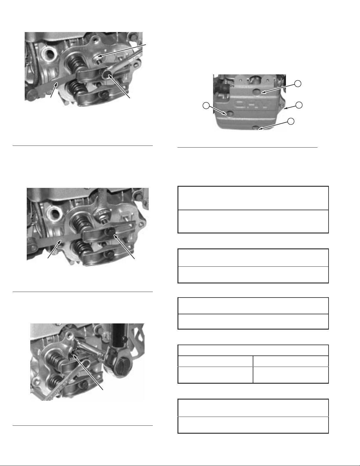
4.
210
Loosen jam nut, Fig. 62.
Install Valve Cover
1
Fig. 62
– Adjust Rocker Arm Clearance,
Early Style
1. Feeler
2.
5. Using
6.
gauge
Jam nut
3.
Rocker arm screw
feeler gauges, check valve clearance. Clearance
should be as listed in T
able No. 4, Page 32.
If not, adjust by turning rocker arm screw until correct
clearance is obtained, Fig. 63.
1. Install
2
2.
valve cover with new gasket. Install four screws.
and tighten screws to torque listed in T
able No. 5, Page 32,
in sequence shown in Fig. 65.
Install carburetor
, exhaust manifold, air guides, shields and
other parts removed from cylinder head.
4
3
1
Fig. 65
– V
alve Cover T
orque Sequence
2
3
Specification Tables
Table No. 1
Valve
Guide Reject Dimensions
Intake and Exhaust
Gauge or Dimension
1
1. Feeler
7. While
Fig. 63 – Adjusting V
gauge
holding screw
, torque jam nut to 85 in. lbs.
alve Clearance
2.
Rocker arm screw
(10.0Nm) and recheck clearance, Fig. 64. Recheck valve
clearances and readjust, if required.
Briggs & Stratton T
ool #19122
.260”
(6.60mm)
Table No. 2
Rocker Arm Stud (Curretn Style) T
2
In. Lb. (Nm)
100
(11.0)
orque
Table No. 3
Cylinder
Head Screw T
orque
In. Lb. (Nm)
210
(24.0)
Table No. 4
Valve
Clearances
Intake Exhaust
.004–.008
(.10-.20mm)
.004–.008
(.10-.20mm)
1. Torque
jam nut 85 in. lbs. (10Nm)
Compression
Fig. 64
1
– Locking Jam Nut
32
Table No. 5
V
alve Cover T
In. Lb. (Nm)
85
(10.0)
orques
GTS 200
Page 35

Rewind
Starter
Contents
General
Remove Blower Housing and Starter33. . . . . . . . . . . . . . . . .
Disassemble Rewind Starter34. . . . . . . . . . . . . . . . . . . . . . . .
Assemble Rewind Starter36. . . . . . . . . . . . . . . . . . . . . . . . . . .
Information33. . . . . . . . . . . . . . . . . . . . . . . . . . . . . . .
Remove Rope34. . . . . . . . . . . . . . . . . . . . . . . . . . . . . . .
Inspect Rope34. . . . . . . . . . . . . . . . . . . . . . . . . . . . . . . .
Remove Pulley And Spring35. . . . . . . . . . . . . . . . . . . . .
Inspect Spring, Starter Housing and Pulley35. . . . . . . .
Install Pulley and Spring36. . . . . . . . . . . . . . . . . . . . . . .
Install Pawls and Retainer Assembly36. . . . . . . . . . . . .
W
ind Spring and Install Rope36. . . . . . . . . . . . . . . . . . .
Install Rewind Starter on Blower Housing37. . . . . . . . .
Install Blower Housing and Rewind Starter37. . . . . . . .
Install Fuel T
ank 37
. . . . . . . . . . . . . . . . . . . . . . . . . . . . .
Remove
Starter
1. Remove
cover screw and air cleaner cover
3
Blower Housing and
, Fig. 67.
1
2
4
General
Fig.
66 – Rewind Starter
Information
, Exploded V
iew
Fig. 67
1. Knob
2. Cover
2. Remove
Remove cover
Fig. 68
1. Screw
– Removing Air Cleaner Cover
3. Foam
4.
four (4) screws from rewind cover
.
– Removing Blower Housing Cover
pre–cleaner
Paper cartridge
, Fig. 68.
11
m–3664
GTS 200
33
Rewind
Starter
Page 36

3. Disconnect
R
Remove three (3) screws holding fuel tank to blower
housing and screw and spacer holding tank to cylinder
Fig. 69.
Note:
engine with a fuel tank mounting bracket. One screw holds
tank to bottom of fuel tank bracket. The other screw holds
tank to side of cylinder with a screw
plastic spacer
fuel line at carburetor and clamp fuel line.
Some models have fuel tanks that are held on the
, rubber washer and
. Slide fuel tank up off fuel tank bracket.
1
5. Remove
from rear of blower housing, Fig. 71.
,
Note:
the blower housing. Replacement starters are supplied with
screws and nuts to replace the rivets for mounting starter
1. Screw
four (4) screws, two (2) from front and two (2)
Rewind starters used on these engines are riveted to
1
1
1
Fig. 71
– Removing Blower Housing
.
1
Fig 69
– Removing Fuel T
1. Screw 2. Fuel
4. Remove
remove tube, Fig. 70.
Note:
the rear of the engine that must be removed before the
blower housing can be removed. 21” commercial mower
engines use a four (4) quart fuel tank.
1. Screws
2.
Blower housing and
rewind starter
screw holding oil fill tube to blower housing and
Some engines have a fuel tank bracket mounted on
2
1
Fig. 70
(2)
– Removing Oil Fill T
2
ank
tank
ube
3.
Dipstick and oil fill tube
Disassemble
Rewind Starter
Remove Rope
1. Pull
2.
3.
4.
starter rope out as far as it will go.
While holding pulley and starter housing, pull pulley end
of rope out and untie knot at end of rope.
Remove rope and handle from starter
Slowly release pulley to release spring tension.
.
Inspect Rope
1. Inspect
3
1
2.
3.
4. W
rope for fraying or broken strands.
Replace if frayed or broken strands are found.
If re-using old rope, burn each end of rope with an open
flame.
ipe with waste cloth, using caution, while it is still hot,
to prevent swelling and unravelling.
Note:
When installing a new rope, check parts list to be
sure correct diameter and rope length is used. The service
replacement rope is cut to length as required: See
T
able No. 1.
Table No. 1
Rewind Starter Rope Specifications
Length
ope Size
Inches Meters
#5 88–5/8 2.25
Rewind Starter
34
GTS 200
Page 37
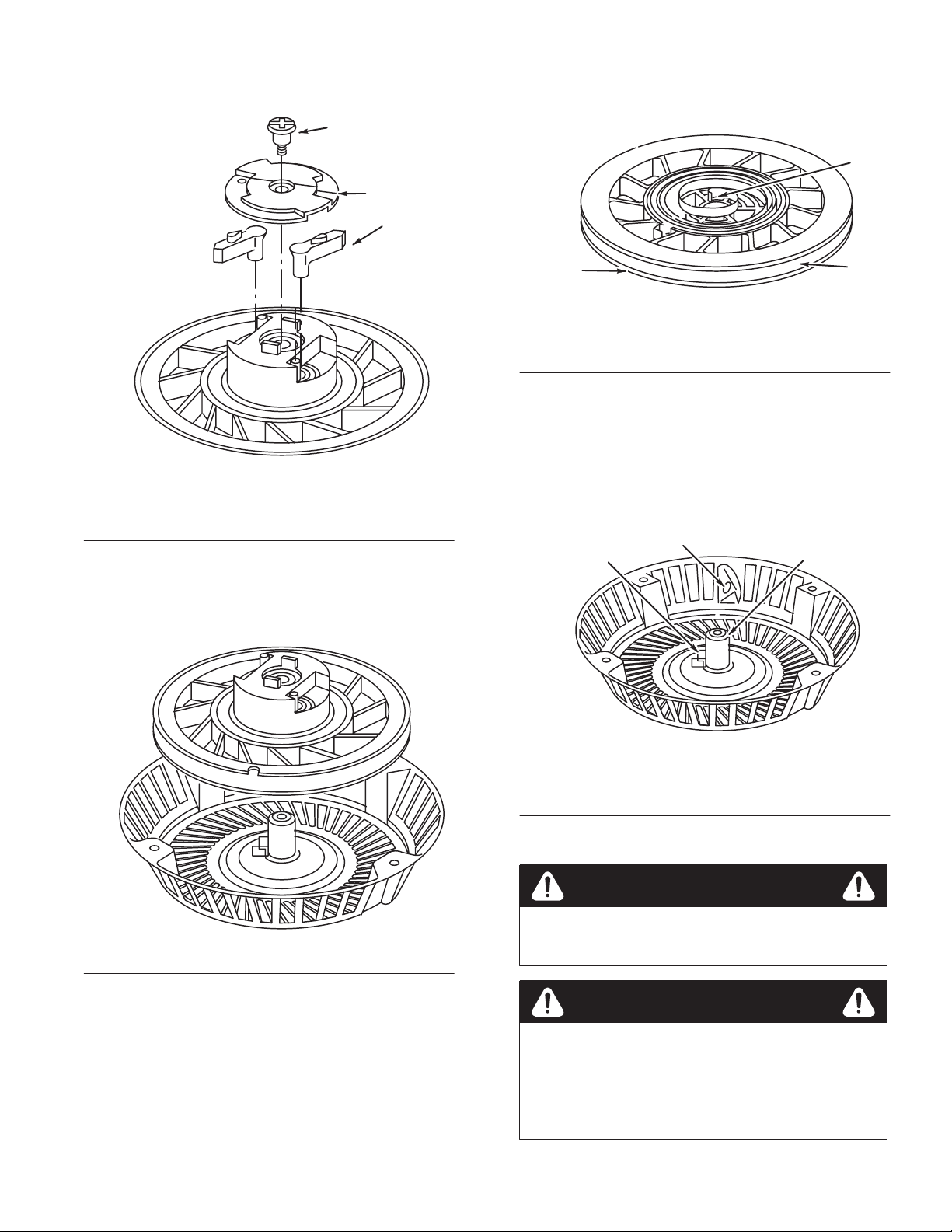
Remove Pulley And Spring
Inspect Spring, Starter Housing and Pulley
1. Remove
shoulder screw and retainer
Fig. 72
1. Shoulder screw
2. Retainer
2. Lift
out pawls.
, Fig. 72.
1
– Removing Retainer
3. Pawls
1. Inspect
pulley for wear
, cracks, rough edges or burrs in
pulley groove and wear on center hole, Fig. 74.
2
2
3
1
3
Fig. 74 – Inspecting Pulley
1. Edges
2. Center
2. Replace
3.
hole
pulley if damaged or worn.
Inspect spring for broken ends, kinks and burrs. Replace
3.
Pulley groove
assembly if any of above conditions exists.
4.
Inspect starter housing for wear or sharp edges at rope
eyelet, center pivot post, and inner spring anchor tab,
Fig. 75.
2
1
3
3.
Rotate pulley until pulley feels free.
4.
Carefully lift out pulley with spring, Fig. 73.
Fig. 73
– Removing Pulley
Fig. 75 – Inspecting Starter Housing
1. Inner
2.
5. Replace
spring anchor
Rope eyelet
assembly if worn or damaged.
3.
Center pivot point
CAUTION
PULLEY AND spring is serviced as an assembly
Do not r
emove spring fr
om pulley
.
WARNING
THE STARTER spring is still under tension when
the r
ope has been r
spring tension against it. W
pr
event eye injury when installing or r
starter pulley and spring.
emoved and the pulley has no
ear eye pr
otection to
emoving
.
GTS 200
35
Rewind
Starter
Page 38

Assemble
Rewind Starter
Install Pulley and Spring
1. Lay
2.
starter housing on work bench.
Assemble starter pulley to center pivot post in housing,
Fig. 76.
2. Install
tabs on pulley
retainer making sure that slots in retainer engage
, Fig. 79.
2
3
1
2
Fig. 76 – Installing Pulley
1. Pulley 2. Center
3. Rotate
pulley counterclockwise until slight resistance is
pivot post
felt, indicating that spring is engaged in spring tab in
housing, Fig. 77.
1
Fig. 79
1. Slot
2. Torque
(8.0Nm)
3. Hold retainer dow
t
o 70 in. lbs. (8.0Nm)
4.
While holding retainer
– Installing Retainer and Screw
3. Retainer
screw to 70 in. lbs.
n and i
4. Tab
nstall retaine
r s
, rotate pulley to extend and retract
crew. Torqu
pawls. If they do not extend and retract, remove retainer
and install again.
Wind Spring and Install Rope
4
e s
crew
1
Fig. 77
1. Counterclockwise
– Engaging Spring
Install Pawls and Retainer Assembly
1. Position
1. Posts 2. Pawls
pawls over posts in pulley and install, Fig. 78.
2
1
Fig. 78
– Installing Pawls
1. Turn
pulley counterclockwise until spring is wound tight,
Fig. 80.
3
4
1. Starter
2.
Pulley rope hole
2. Then
rotate pulley clockwise until rope hole in pulley is in
Fig. 80
housing eyelet
– W
inding Spring
3. Counterclockwise
4. Clockwise
line with starter housing eyelet and hold pulley
1
2
, Fig. 80.
Rewind
Starter
36
GTS 200
Page 39

3. Insert
4.
unknotted end of rope through knot cavity and rope
hole in pulley
.
Thread end of rope through starter housing eyelet and pull
rope until knot is in rope cavity
, Fig. 81.
1
3. Tighten
screw and then install three remaining screws.
Install oil fill tube and dipstick.
Note:
Install fuel tank bracket with blower housing. After
torquing blower housing screws install one (1) screw at top
of fuel tank bracket to top of blower housing and torque
screw to 85 in. lbs. (10.0Nm).
4.
Install oil fill tube and dipstick and torque screw to
45 in. lbs. (5.0Nm).
Note:
The oil fill tube screw is installed on fuel tank
2
bracket to same torque listed in Step 4.
Install Fuel Tank
Fig. 81 – Inserting Rope
1. Starter
5. While
housing eyelet
2.
Pulley rope hole
holding starter rope handle, slowly let pulley pull
starter rope into starter
.
Install Rewind Starter on Blower Housing
1. If
rewind starter housing was removed from blower
housing, see parts manual for screws and nuts.
Install Blower Housing and Rewind Starter
1. Place
2.
blower housing on engine and start one (1) screw in
extruded hole.
Hold blower housing with extruded hole in recess of
cylinder block, Fig. 82.
1. Install
fuel tank by sliding tank mounting bosses into slots
on fuel tank bracket until tank bottoms in slots.
2.
Start, but do not tighten screws into bottom of fuel tank
bracket.
Install shoulder screw between fuel tank and side tank
3.
mounting boss. Install shoulder screw and torque screw to
85 in. lbs. (10.0Nm), Fig. 83.
21
Fig. 83 – Installing Fuel Tank
1. Torque
screw to 45 in. lbs.
(5.0Nm)
2. T
orque shoulder screw to
85 in. lbs. (9.6Nm)
1. Tighten
GTS 200
2
1
Fig. 82 – Installing Blower Housing
first
2. T
ighten second
37
4. Torque
Fig. 83.
Note:
lower tank mounting screw to 45 in. lbs. (5.0Nm),
21” commercial mowers use a remote fuel tank.
Rewind
Starter
Page 40

Electric
Starter
Contents
General
T
T
Battery 40
Starter 41
Information38. . . . . . . . . . . . . . . . . . . . . . . . . . . . . . .
roubleshooting 12 V
est Equipment39. . . . . . . . . . . . . . . . . . . . . . . . . . . . . . . . . .
Digital Multimeter39. . . . . . . . . . . . . . . . . . . . . . . . . . . .
DC Shunt39. . . . . . . . . . . . . . . . . . . . . . . . . . . . . . . . . . .
Tachometer 39
Starter T
Other Equipment39. . . . . . . . . . . . . . . . . . . . . . . . . . . . .
Handling Instructions40. . . . . . . . . . . . . . . . . . . . . . . . .
First Aid40. . . . . . . . . . . . . . . . . . . . . . . . . . . . . . . . . . .
Check Battery40. . . . . . . . . . . . . . . . . . . . . . . . . . . . . . .
Replace Battery T
Check Starter Motor Drive and Clutch41. . . . . . . . . . . .
W
Check 12 V
Starter Motor Specifications41. . . . . . . . . . . . . . . . . . . .
T
Check Brake Switch42. . . . . . . . . . . . . . . . . . . . . . . . . .
Check Brake Switch W
Disassemble Starter Motor42. . . . . . . . . . . . . . . . . . . . .
Clean and Inspect Starter43. . . . . . . . . . . . . . . . . . . . . . .
Assemble Starter Motor43. . . . . . . . . . . . . . . . . . . . . . .
Install Starter44. . . . . . . . . . . . . . . . . . . . . . . . . . . . . . . .
est Bracket39. . . . . . . . . . . . . . . . . . . . . . . . . . .
. . . . . . . . . . . . . . . . . . . . . . . . . . . . . . . . . . . . . . . . .
. . . . . . . . . . . . . . . . . . . . . . . . . . . . . . . . . . . . . . . . . .
iring Diagrams41. . . . . . . . . . . . . . . . . . . . . . . . . . . . .
roubleshoot Starter Motor41. . . . . . . . . . . . . . . . . . . . .
olt Starting System38. . . . . . . . . . . . . .
. . . . . . . . . . . . . . . . . . . . . . . . . . . . . . . . .
erminal 40
olt Starter Motor41. . . . . . . . . . . . . . . . . . . .
. . . . . . . . . . . . . . . . . . . . . .
iring 42
. . . . . . . . . . . . . . . . . . . .
When
the starter switch is activated, the battery supplies
power to the starter motor
newer models, the brake switch must also be activated to
power the starter
rechar
ges the battery
minutes of running to replace the battery char
the engine one time.
Should the battery need additional rechar
char
ger is plugged into a 120 volt AC household outlet, and
then connected to battery
within a 72 hour period. It is not recommended that battery be
rechar
ged if temperatures are below 40° F (4° C). For best
results, char
(4°C) to 105° F (41° C). When long periods of storage are
encountered, battery should be char
months. This type of battery will lose its char
use. This may shorten battery life.
. When the engine is running, the alternator
ge battery within temperature limits of 40° F
, cranking the engine. On 1999 and
. It will take approximately 15–20
ge used to start
ging, the trickle
. The battery will be fully char
ged overnight every two
ge when not in
ged
Troubleshooting
12 Volt Starting System
The
following list is given to aid in diagnosing problems for
12 volt starting systems.
Note:
If a starting problem is encountered, the engine itself
should be thoroughly checked to eliminate it as the cause of
starting dif
freedom of rotation by removing spark plug and turning
crankshaft over by hand, to be sure it rotates freely
1.
ficulty
. It is a good practice to check engine for
Engine Cranks Slowly
A.
Additional load af
B. Dischar
ged battery
fecting performance.
.
.
General
The T
oro GTS 200 electric start system consists of a 12V
battery
, starter motor
1999 and newer models have a brake switch and a fuse for the
char
ging system. A separate trickle char
The starter motor uses a gear type engagement method,
similar to an automobile starter
a pinion gear into engagement with a ring gear attached to the
engine flywheel and cranks the engine. See Fig. 84 for
location of starter motor
1. Connector 2. 12
Information
, switch, and alternator
.
1
Fig. 84
– Electric Start Engine
. In addition, the
ger is also standard.
. The starter motor shaft drives
2
volt starter motor
C.
Faulty electrical connection (battery circuit).
D.
Dirty or worn starter motor commutator
magnets, etc.
E. W
orn brushes or weak brush springs.
F. W
rong oil viscosity for temperature expected.
G.
Flywheel brake mis-adjusted.
2.
Engine W
A. Dischar
B.
C.
D.
E.
3.
Starter Motor Spins,
But Does Not Crank Engine
A.
B.
C.
ill Not Crank
ged or defective battery
Faulty electrical connections.
Faulty starter motor switch (open circuit).
Open circuit in starter motor
Brushes sticking, etc.
Sticking pinion gear due to dirt or damaged spline.
Damaged pinion or ring gear
Starter pinion clutch slipping.
.
.
.
, bearing, weak
Electric
Starter
38
GTS 200
Page 41

D. Battery
E.
Incorrect rotation due to reversed motor polarity or
faulty or damaged.
reverse battery connections – motor rotates
counterclockwise viewed from pinion gear
4.
Starter Motor Spins, W
A.
Defective starter switch.
ill Not Stop
Tachometer
A T
rysit Sirometer (T
& Stratton source of supply
.
#19200. The Sirometer measures from 800 to 25,000
revolutions per minute (RPM), Fig. 87.
achometer) is available from your Briggs
. Use Briggs & Stratton T
ool
Test
The
Equipment
following is a list of equipment recommended to test and
repair starter motors , and to test batteries.
Digital Multimeter
A
Digital Multimeter is recommended. The meter may be
used to read volts, ohms or amperes, and test diodes
(rectifiers) when test leads are inserted in the appropriate
receptacle, Fig. 85.
Fig. 85
– Digital Multimeter
DC Shunt
Use
with Digital Multimeter
read starter motor current draw on 12 volt starter motors. Use
Briggs & Stratton T
ool #19359, Fig. 86.
. The DC Shunt may be used to
Fig. 87 – T
rysit Sirometer (T
achometer)
Starter Test Bracket
A
starter motor test bracket may be made as shown in Fig. 88.
1
2–1/4”
4”
(102mm)
3–1/2”
(89mm)
(57mm)
1” (25mm)
10” (254mm)
Fig. 88 – Starter Mounting T
1. Extra
2.
hole for mounting
starter brackets
Drill two holes 3/8”
(10mm) diameter for
starter mounting bracket
2
3–1/2” (89mm)
est Bracket
3.
Drill two holes for
mounting Briggs &
Stratton T
tachometer #7 drill tap
hole
4. Metal
thick steel
ool #19200
for
1/4–20 NC screws
stock 1/4” (6mm)
3
2” (51mm)
4
GTS 200
Fig. 86
– DC Shunt
2–1/4” (57mm)
Fig. 89
5/8”
(16mm)
– Brush Spreader
2” (51mm)
Other Equipment
A
growler or armature tester (checks armature for continuity
shorts and opens) is available from an Automobile Diagnostic
Service supplier
A known good 12 volt battery is required when testing 12 volt
starting systems.
39
.
Electric
,
Starter
Page 42

Battery
Handling Instructions
CAUTION
LIKE
ALL batteries, these units contain corr
fluids and toxic materials and should be handled
with car
•
•
•
•
•
• A
e.
Do not puncture, disassemble, mutilate or incinerate.
As with all rechar
be vented during char
ventilated area, away from sources of ignition.
Battery should be rechar
Use only the battery charger specified.
Do not make direct contact between the positive and
negative terminals as this could cause high current flow
creating high heat and the possibility of a fire.
void any direct connection of battery terminals that will
cause the battery to short out.
geable batteries, explosive gases could
ge or dischar
ged by adults only
ge. Use in a well
.
osive
2.
Fully char
Install battery on mower
3.
4.
Slightly loosen battery plug and attach DC voltmeter
Reading should be around 12.5 VDC.
5.
Disconnect spark plug wire and turn switch to start.
6.
Battery should maintain 9 volts or more while cranking
engine. If it is less than 9 volts, replace battery
Alternate method: T
#67–7970, Fig. 90. Instructions provided on tester
,
ge battery with char
. Plug into wire harness.
est using T
oro Keylectric tester
ger supplied with the mower
.
.
, T
oro Part
.
.
First Aid
CAUTION
IF
THE battery case cracks or br
r
esult of sever
comes in contact with skin or clothing, follow
these instructions:
•
External Contact – Immediately flush skin or
eyes with water for at least 15 minutes.
•
Internal Contact – Drink tap water
milk of magnesia. T
induce vomiting.
e abuse and some of the liquid
ake whites of eggs. Do not
eaks open as the
, milk, or
WARNING
IN CASE of external or internal contact, call a
physician immediately
Check Battery
1. Physical
check – clean if necessary
.
.
Fig. 90
– Keylectric T
ester
CAUTION
DO
NOT crank starter motor for mor
seconds without cooling starter 2 minutes.
Replace Battery Terminal
Toro
Part #49–8141 is a replacement plug with two solderless
connectors (Fig. 91). It can be used when the plug or lead
wires between the plug and battery are damaged.
e than 15
A. Corrosion
B. Dirt
C. T
with T
Electric
erminal – clean, undamaged. Replace if damaged
oro Part #49–8141.
Starter
40
Fig. 91
– Replacement Battery T
T
oro Part #49–8141
erminal
GTS 200
Page 43

Starter
Check Starter Motor Drive and Clutch
1. When
starter switch is activated, pinion gear should rise,
engage flywheel ring gear
, and crank engine. This should
be observed.
Check 12 Volt Starter Motor
A
performance test of starter motor may be made in the
following manner
.
CAUTION
2.
If starter motor drive does not react properly
, inspect helix
and pinion gear for freeness of operation.
3.
Pinion gear must move freely on helix for correct starter
operation. If any sticking occurs, this must be corrected,
Fig. 92.
Note:
Do not oil pinion gear on clutch helix.
1
2
Fig. 92
1. Helix 2. Starter
4. Starter
motor clutch is designed to prevent damage from
– Starter Motor Drive
gear
shock loads such as an engine backfire.
5.
Clutch should not slip during normal engine cranking. This
can be checked by blocking mower blade and engaging
starter motor
.
GROUND SP
Stratton T
befor
e doing this test. Do not engage starter motor
mor
e than five seconds.
1.
Set multimeter to read DC amps. Multimeter must be
ARK plug wir
e using Briggs &
ool #19051 or #19368, Ignition T
ester,
capable of reading 10 amps DC minimum.
2.
Connect starter motor
, battery and meter as shown in
Fig. 94.
3.
Place tachometer on starter body and activate starter motor
as shown, Fig. 94.
2
6.
If clutch assembly slips at this time, it should be replaced.
Wiring Diagrams
The
following wiring diagrams (Fig. 93) show the two systems
used with the GTS 200 engine.
Fig. 93 – T
T
oro W
ypical W
iring Diagrams for
alk Behind Mowers
1
Fig. 94 – T
3
esting Starter Motor with Digital
4
Multimeter
1. Red
test lead
2.
Black test lead
3.
Briggs & Stratton T
#19200
4.
12 volt battery
Starter Motor Specifications
Voltage .
Minimum
Maximum
. . . . . . . . . . . . . . . .
motor RPM. . . .
amps. . . . . . . . .
12
1400
9
Troubleshoot Starter Motor
If
starter motor does not perform satisfactorily
should be checked, and corrected if necessary
A binding condition between pinion and clutch gear or
1.
misalignment of motor bearings.
, following
.
ool
GTS 200
41
2.
Starter motor brushes sticking in brush holders.
Electric Starter
Page 44

3. A
dirty or worn armature commutator
A shorted, open or grounded armature.
4.
A.
Shorted armature (worn insulation, wires touching each
.
other) will be indicated by slow speed and high current
(amps).
Open armature (broken wire) may not turn (no current
B.
flow [amps]) or will have low RPM.
C.
Grounded armature (worn insulation, wire touching
armature) will not turn or may turn slowly and will
have excessive current (amps).
D. W
eak, loose, or cracked magnets.
5.
Armature end play, too much or none.
6.
Defective starter motor brake switch.
5.
Move wire inside connector
. Meter should not change
value.
6.
Replace or repair wiring if there is no continuity or
intermittent. Repeat for each wire in harness.
Disassemble Starter Motor
CAUTION
DO
NOT clamp motor housing in a vise or strike
with a steel hammer
ceramic magnets which can be br
if motor housing is deformed or dented.
1.
Study Fig. 96 prior to starter motor disassembly
. Starter motors contain two
oken or cracked
.
Check Brake Switch
1. Disconnect
switch.
2.
Set meter to read Ω ohms. Zero meter
3.
Connect meter test leads to two spade terminals of switch
(Fig. 95). Meter should read no continuity
interlock switch wires from spade terminals on
, if required.
.
10
12
11
1
2
3
4
5
6
7
8
9
14
15
16
17
4. Push
Fig. 95
switch lever in until switch clicks. Meter should read
– Checking the Brake Switch
low resistance.
Check Brake Switch Wiring
1. Disconnect
switch and at starter motor connector
Set meter to read Ω ohms. Zero meter
2.
3.
Connect one meter test lead to end of one wire inside
connector and other test lead to second connector terminal
for the same wire.
4.
Meter should read low or no resistance.
Electric
interlock switch wires from spade terminals on
.
, if required.
Starter
1. ’’E’’
2.
3.
4.
5. Cover
6. Gasket
7.
8.
9.
10.
2. Remove
42
13
Fig. 96
retaining ring
Starter gear helix
Pinion gear
Screws (3)
Felt washer
Drive gear
Pinion gear
Drive end head bracket
“E” retaining ring and pinion gear
– Exploded V
11.
Thru bolts (2)
12. Housing
Brush end cap (with
13.
brushes, springs, and
connectors)
End play washers
14.
15. Armature
16. Commutator
17.
Thrust washers
iew
.
GTS 200
Page 45

3. Three
(3) screws holding gear cover and gear itself may
now be removed.
4.
Lift clutch assembly and pinion gear of
f their respective
shafts.
5.
Remove starter motor thru bolts, Fig. 97.
2
1
3
Fig. 97
1. Housing
cap
2. End
6. Separate
7.
Push motor armature out through bottom of starter
motor end cap from motor housing.
– Removing Thru Bolts
3.
Remove thru bolts
housing, taking care to slide plastic mounted terminal out
of motor housing along with end cap, Fig. 98.
2
1
3
10.If
brushes are worn to a length of 5/64” (2mm) or less,
brushes should be replaced.
11. Chec
k b
o keep b
t
rus
rus
h s
h i
pring
n fir
s f
or proper tension (sufficient force
m c
ontac
t with c
ommutator).
Clean and Inspect Starter
1. Clean
2.
3.
4.
5.
Starter motor armatures have very low resistance, usually
below detection on available multimeters. T
shorted armatures, a piece of equipment known as a “growler”
may be used. If this equipment is not available, a known good
armature should be tried and performance rechecked.
all dirt from armature, end cap, motor support,
gears, etc.
End cap bearings and armature should not be soaked in a
solvent.
Armature commutator may be cleaned with a fine
sandpaper or commutator paper
Note:
Do not use any metallic oxide paper or emery cloth,
.
as metallic oxide or emery will become embedded in
commutator causing rapid brush wear
.
If armature is suspected to be defective, a new armature
should be tried in motor
.
If proper testing equipment is available, check suspected
armature to determine if it is defective.
o check for
4
– Removing Armature
3. Housing
Armature shaft
4.
1. Terminal
cap
2. End
8. Before
Fig. 98
removing armature from end cap, check brushes for
freedom of movement.
9.
If brushes are found to be sticking in their retainers, this
must be corrected, or poor starter motor performance will
result, Fig. 99.
5/64”
1. Brushes
(2mm)
Fig. 99
– Checking Brushes
1
If magnets are loose or cracked, a new motor housing should
be tried.
Assemble Starter Motor
1. When
2.
1
2
1. Gray
2. Armature
3.
all parts have been thoroughly inspected, lightly
lubricate bearings with an oil made for use in electric
motors and reassemble in following manner
.
Insert brush springs and brushes in holders as far as
possible, and hold them in this position with tool shown in
Figs. 89 and 100.
4
Fig. 100
Brush spreader
– Armature Assembly to End Cap
plastic washers
1
3
4.
.176” (4.47mm) thick fiber
washer
5.
.030” (.76mm) thick steel
washer
5
.225”
(5.72mm)
.200”
(5.1mm)
GTS 200
43
Electric
Starter
Page 46

3. Place
4.
thrust washers on armature shaft in sequence shown.
Add gray plastic washers to obtain dimension shown in
Fig. 100, inset.
5.
Using care to ensure brushes clear commutator
armature shaft into end cap bearing.
6.
Support armature shaft and slide it slowly into starter
housing, as shown in Fig. 101.
, slide
17.Tap
end cap edge lightly using a soft hammer to align
bearings, Fig. 103.
1
2
1
2
1. Terminal
2. Housing
7. Insert
Fig. 101
plastic insulator terminal into starter housing at this
– Inserting Armature
3. Notch
time.
8.
Place remaining thrust washers on motor PT
O shaft. Install
end head cover and thru bolts.
9. T
orque through bolts to 25 in. lbs (3.0Nm).
10.
Notches in end cap, housing and end head must be aligned,
Fig. 101.
11.
Check for end play to obtain .005” (13mm) to .025”
(64mm) armature movement.
12.
If required, install or remove gray plastic washers between
armature and drive end head to obtain end play
.
3
3
1. Drain
2. T
Fig. 103
hole
ap edge of end cap
18.Re-torque
19.Replac
Note:
Do not oil pinion gear or clutch helix.
– Aligning End Cap Bearing
3.
screws to 25 in. lbs. (3.0Nm).
e p
inio
n gear and “E” r
etaining rin
Soft hammer
g a
ssembly.
Install Starter
1. Install
2.
starter on engine and start mounting screws. While
holding starter against locating lugs on cylinder
torque mounting screws to 140 in. lbs. (16.0Nm).
Reinstall starter guard, when used.
2
1
4
, Fig. 104,
3
13.
Slip pinion and starter motor clutch gear on shaft.
14.
Add approximately 3/4 ounce of Briggs & Stratton Part
#100060 grease under lar
15.
Oil felt washer with electric motor oil.
16.
Install washer
, gasket and cover
ge gear and on gear teeth.
, Fig. 102.
1
1. Apply
Electric
Fig. 102
lubricant here
Starter
– Lubricating Gears
2.
Oil felt washer
2
Fig. 104
1. Wire
2. T
1
clip
orque screws to
140 in. lbs. (16.0Nm)
44
– Installing Starter
3. Lug
4.
Alternator wire(s)
GTS 200
Page 47

Alternator
Contents
Equipment
The
following equipment is recommended to test and repair
alternators.
to T
est Alternators
Alternator
Equipment to T
1/2 Amp Alternator45. . . . . . . . . . . . . . . . . . . . . . . . . . . . . . .
Alternator
Alternator type .
Alternator output* .
(at
*
Alternator output is determined by flywheel alternator
magnet size.
Note:
engine speed is lowered.
Specifications45. . . . . . . . . . . . . . . . . . . . . . . . . . .
est Alternators45. . . . . . . . . . . . . . . . . . . . . . .
Digital Multimeter45. . . . . . . . . . . . . . . . . . . . . . . . . . . .
T
est Alternator Output45. . . . . . . . . . . . . . . . . . . . . . . . .
Install Stator Studs46. . . . . . . . . . . . . . . . . . . . . . . . . . .
Adjust Stator Air Gap46. . . . . . . . . . . . . . . . . . . . . . . . .
Specifications
. . . . . . . . . DC only
. . . . . .
2800 RPM)
Alternator is rated at 2800 RPM. Output is reduced as
not less than
0.5 amps DC (+)
3
2
Digital Multimeter
Use
a Digital Multimeter. The meter may be used to read
volts, ohms or amperes, and test diodes, when leads are
inserted in appropriate receptacles, Fig. 106.
Fig. 106
1/2
Amp Alternator
The 1/
2 amp D
t o
f th
par
system. I
vol
t b
attery.
e e
t i
ngin
s i
ntende
C a
– Digital Multimeter
lternator i
e and i
d t
s s
o p
s d
eparat
rovid
esigne
e from the s
e D
C c
d t
o o
hargin
perat
tartin
g c
e a
s a
n i
g and i
urrent fo
ntegral
gnition
r a 1
2
1
.
lead.
– 1/2 Amp
1. Stator
2. Black
3. White
Fig. 105
• 0.5
amps DC for charging
battery.
•
One black lead from stator
connector output
• White
Alternator Systems – Troubleshooting
Complaint Possible
Battery not
charging
•
Engine RPM too low
•
Defective battery
•
Loose, pinched, or corroded battery
ground leads.
•
Loose, pinched, or corroded battery
charge leads.
•
Open, shorted, or grounded wires be
tween output connector and battery
•
Damaged battery (shorted battery
cells).
Damaged alternator magnets.
•
•
Defective stator
Causes
.
.
assembly
.
2
1
– 1/2 Amp Alternator
2. Black
1. Stator
Fig. 107
assembly
Test Alternator Output
Disconnect
-
.
1.
Insert RED test lead into 10 A receptacle in meter
2. Inser
3.
Rotate selector to
char
ging lead to battery at connector
t B
LAC
K test lead into COM r
.
eceptacl
e i
n m
(DC amps) position.
.
eter.
GTS 200
45
Alternator
Page 48

4.
Attach RED test clip to output terminal, Fig. 108.
Adjust Stator Air Gap
Fig. 108 – Testing Alternator Output
1. Connector
2. Black
5. Attach
lead
BLACK test clip to char
disconnected at the connector
1
3.
Red lead
ging lead that was
.
2
1. Stator
2. Rotat
3.
4.
air gap is 0.010” (.25mm).
e f
lywhee
l u
nti
l m
agnet
s are a
way fro
m s
tator.
Loosen both stator mounting screws and move stator away
from flywheel and tighten one screw
.
Place a 0.010” (.25mm) thick gauge between stator and
flywheel.
3
5. T
urn flywheel until magnets are under stator
. Loosen
screw and let stator be pulled against flywheel magnet.
6. T
orque mounting screws to 25 in. lbs. (2.8Nm).
7. T
urn flywheel to remove gauge, Fig. 109.
6. W
ith engine running at least 2800 RPM, output should be
no less than 0.5 amp DC.
7.
If low or no output, check stator air gap, Fig. 109.
1
Fig. 109
1. 0.010”
8. If
(.25mm) gauge
stator air gap is within specification and there is low or
no output, replace stator
– Adjusting Air Gap
2.
25 in. lbs. (2.8Nm)
.
2
Install Stator Studs
If
stator studs were removed, install and torque to 30 in. lbs
(3.4Nm), Fig. 109.
Alternator
.
46
GTS 200
Page 49

Lubrication
2
Contents
Extended Oil Fill and Dipstick47. . . . . . . . . . . . . . . . . . . . . .
Breather 47
Remove Breather47. . . . . . . . . . . . . . . . . . . . . . . . . . . . . . . . .
Install Breather V
Remove Oil Pump47. . . . . . . . . . . . . . . . . . . . . . . . . . . . . . . .
Inspect Oil Pump48. . . . . . . . . . . . . . . . . . . . . . . . . . . . . . . . .
Install Oil Pump48. . . . . . . . . . . . . . . . . . . . . . . . . . . . . . . . . .
Install Pump Cover48. . . . . . . . . . . . . . . . . . . . . . . . . . . . . . .
Install Oil Filter Adapter48. . . . . . . . . . . . . . . . . . . . . . . . . . .
Extended
The
turn screw-on-dipstick.
Dipstick oil fill tube is pressed into crankcase cover
. . . . . . . . . . . . . . . . . . . . . . . . . . . . . . . . . . . . . . . .
alve 47
. . . . . . . . . . . . . . . . . . . . . . . . . . . . . .
Oil Fill and Dipstick
GTS 200 uses a plastic extended oil fill tube and a quarter
.
1
2
1
3
1
Fig. 111
1. Gasket
2. Breather
Install
1. Install
cover on cylinder channel and torque four (4) screws to
30 in. lbs. (3.0Nm).
– Removing Breather and Breather
Passage Cover
3. Breather
passage cover
Breather V
new breather passage gasket and breather passage
alve
3
Fig. 110 – Oil Fill and Dipstick
1. Dipstick
2. Oil
fill tube
3.
“O” ring
Breather
The
GTS 200 engine uses a breather valve to control and
maintain a partial vacuum in the crankcase.
The breather valve is a fiber disc or reed valve which closes
on the piston’
stroke to keep a partial vacuum in the crankcase.
This partial vacuum prevents oil leakage past piston rings,
valve guides, oil seals, governor lever shaft and gaskets.
s up stroke and opens on the piston’
s down
Remove Breather
1. Before
2. Remov
3.
breather can be removed, remove fuel tank,
extended oil fill tube, blower housing, flywheel, and
muffler.
e two s
crew
s h
oldin
g b
reather t
Remove four screws holding breather passage cover and
gasket, Fig. 1
11.
o c
ylinder
, Fig.
111.
2.
Place new breather gasket and breather on cylinder and
install two (2) screws torquing screws to 65 in. lbs.
(7.0Nm), Fig. 1
Gaskets do not require any sealant.
Remove
11.
Oil Pump
(on models so equipped)
1. Oil
pump can be removed without removing sump from
engine.
2.
Remove three screws and remove pump cover and “O”
ring, Figs. 1
3.
Carefully remove inner and outer rotors.
1. Oil
pump cover
12 and 1
Fig. 112
13.
1
– Removing Pump Cover
GTS 200
47
Lubrication
Page 50

Install
Pump Cover
Fig. 113
1. Pump
cover
Inspect
– Removing Oil Pump
Oil Pump
2.
“O” ring
(on models so equipped)
1. Inspect
2.
3.
4.
surfaces of inner and outer rotors, pump housing,
cover
, and shaft for wear and scoring.
Inspect pump housing and passages for debris.
Clean if required.
Replace worn or damaged parts.
1
2
(on models so equipped)
1. Install
2. Place
“O” ring in groove in sump, Fig. 1
Fig. 115
pump cover on oil pump cavity and install three (3)
screws. T
– Installing Pump Cover
orque screws to 35 in. lbs. (4.0Nm).
15.
Install
Oil Pump
(on models so equipped)
1. Oil
and install outer rotor in pump cavity
to install.
2.
Oil and install inner rotor in pump cavity
3. Turn rotor
Place “O” ring in groove in cover
4.
s t
2
o e
1
ngag
e pump i
n cam o
. Do not use force
.
r governor gear.
, Fig. 1
14.
3
4
5
Install
Oil Filter Adapter
(on models so equipped)
Install
oil filter adapter as shown in Fig. 1
85 in. lbs. (10.0Nm).
1
Fig. 116
1. Filter 2. Adapter
– Oil Filter Adapter
16. T
orque screws to
2
1. Outer
2. Groove
3. Cover
Lubrication
rotor
Fig. 114
– Installing Oil Pump
4.
“O” ring
5.
Inner rotor
48
GTS 200
Page 51

Pistons,
Rings, and
Rods
Contents
Piston
and Connecting Rod49. . . . . . . . . . . . . . . . . . . . . . . . .
Remove Piston and Connecting Rod49. . . . . . . . . . . . . .
Remove Piston Rings49. . . . . . . . . . . . . . . . . . . . . . . . .
Check Piston Ring Groove W
Check Piston Ring End Gap50. . . . . . . . . . . . . . . . . . . .
Check Connecting Rod50. . . . . . . . . . . . . . . . . . . . . . . .
Check Piston Pin and Piston Pin Bore50. . . . . . . . . . . .
Assemble Piston and Connecting Rod50. . . . . . . . . . . .
Install Piston Rings On Piston51. . . . . . . . . . . . . . . . . . .
Compress Rings51. . . . . . . . . . . . . . . . . . . . . . . . . . . . . .
Install Connecting Rod and Piston51. . . . . . . . . . . . . . .
Specification T
Piston
Note:
Crankcase cover
piston and rod can be removed, Crankshaft and Camshaft,
page 53.
ables 52
. . . . . . . . . . . . . . . . . . . . . . . . . . . . . . .
and Connecting Rod
or sump must be removed before
ear 50
. . . . . . . . . . . . . . . .
3.
Push piston and rod out through top of cylinder
The GTS 200 engine uses oil drain slots in ring
Note:
lands, Fig. 1
1. Drain
slot
18.
Fig. 118
1
– Oil Control Slots
Remove Piston Rings
Remove
Piston Ring Expander
piston rings using Briggs & Stratton Tool #19340,
, Fig. 1
19.
1
.
Remove Piston and Connecting Rod
1. Remove
Fig. 117 – Remove Piston and Connecting Rod
1. Box
2. Remove
prevent ring breakage.
connecting rod cap, Fig. 1
wrench to remove screws
any carbon or ridge at top of cylinder bore to
17.
Fig. 119
1. Piston
Note:
Some oil control rings consist of two thin steel rails and
a spring expander
1
Briggs & Stratton T
1.
Grasp one end of the steel rail and wind the rail from the
oil ring groove into the next ring groove.
2.
Repeat into the top ring groove and of
– Removing Rings
. These steel rails cannot be removed with
ool #19340, Piston Ring Expander
f the piston.
.
GTS 200
49
Pistons, Rings, and Rods
Page 52

Check Piston Ring Groove Wear
Î
1
1. Clean
2.
carbon from top ring groove.
Place a NEW ring in groove, Fig. 120 and measure space
between ring and ring land, T
able No. 1, page 52.
1
2
Fig. 120
1. Piston 2. New
– Checking Ring Grooves
piston ring
Check Piston Ring End Gap
1. Clean
all carbon from the end of the rings, and from the
cylinder bore.
2
Fig. 122
1. Crankpin
– Checking Rod Bearings
bearing
2.
Piston pin bearing
Check Piston Pin and Piston Pin Bore
If
piston pin is worn .0005” (.013mm) out of round or below
reject size shown in Table 4, it should be replaced.
If piston pin bore, Fig. 123, is worn over reject size, replace
piston.
1
2.
Insert old rings one at a time one inch down into the
cylinder.
Check end gap with feeler gauge, Fig. 121.
3.
2
1
3
Fig. 121
1. Ring
2. Feeler
4. If
gauge
ring gap is greater than shown in T
– Checking Ring End Gap
3.
See T
able 1
able No. 2, page 52,
the ring should be rejected.
Check Connecting Rod
1. Piston
Fig. 123
pin bore
– Checking Piston Pin Bore
Assemble Piston and Connecting Rod
Note:
Pistons on the GTS 200 engine have a shoulder stop on
one side of piston and use only one (1) piston pin lock.
The piston pin is a slip fit in both piston and connecting rod.
Note:
All pistons are made with an of
1.
Piston must be installed with notch or arrow toward
flywheel side of cylinder
2.
Determine correct position of connecting rod relative to
.
notch or arrow on piston, Fig. 124.
1
fset piston pin bore.
If
the crankpin bearing is scored, the rod must be replaced.
Check condition of crankpin bearing surface on crankshaft.
Reject sizes of crankpin bearing hole and piston pin bearing
hole, Fig. 122, are shown in T
able No. 3, page 52.
Pistons, Rings, and Rods
50
1. Notch
Fig. 124
or arrow
– Assembling Piston and Rod
GTS 200
Page 53

3. Insert
4.
5.
piston pin from side opposite shoulder or installed
lock until pin stops against lock or shoulder
.
Install piston pin lock in groove at other end of piston pin.
Be sure lock is firmly set in groove.
Note:
Some rods have the word “
MAG
” cast in the rod on
the flywheel side.
Install Piston Rings On Piston
The
correct piston ring positions are shown in Fig. 125.
1
2
1
3
Install Connecting Rod and Piston
1. Thoroughly
2.
Rotate crankshaft until crankpin journal is at bottom of
stroke.
Note:
piston and rod assembly
Fig. 127.
clean and then oil cylinder bore.
This permits complete entry of compressed rings,
, when pushed into cylinder
1
5
4
,
7
5
4
Fig. 125 – Piston Ring Installation
1. ID
mark
2. Top
3. Center
4. Oil
5. Expander
Compress Rings
1. Oil
piston rings and piston skirt.
2.
Compress rings with Briggs & Stratton T
Compressor
, Fig. 126.
1
2
3
1. Top
2. Skirt
3. Place
Fig. 126
piston and compressor upside down on bench and
– Compressing Rings
3. Projection
push piston down until head of piston is even with edge of
compressor.
4. T
ighten compressor until piston cannot be turned in
compressor.
ool #19070, Ring
2
Fig. 127
1. #19070
2.
Piston skirt
3.
Square hole
4. Piston
3. Install
3
– Installing Piston Assembly
ring compressor
piston with notch or arrow toward flywheel side of
6
5. Wrench
op of piston and ring
6. T
compressor flush
7. T
op of piston
engine, Fig. 128, taking care not to damage crankpin
journal or connecting rod journal, when installing.
1
1. Notch
4. Clean
Fig. 128
or arrow
and oil crankshaft crankpin.
– Installing Piston Assembly
5.
Then loosen compressor until piston can be turned with
slight resistance.
Note:
Do not attempt to install piston and ring assembly
without ring compressor
.
GTS 200
51
Pistons, Rings, and Rods
Page 54

5. Pull
1. Match
connecting rod against crankpin and install rod cap
with match marks aligned, Fig. 129.
1
Fig. 129 – Rod and Cap Alignment
marks
6. Cap
7. T
8.
9.
should snap on when assembled correctly
screws.
orque connecting rods screws, using Briggs & Stratton
T
ool #
1919
7 o
r 19393, Torqu
liste
d i
n T
abl
e No. 5, page 5
F
ailur
e t
Note:
causin
g b
scoring.
Rotate crankshaft two (2) revolutions to make sure
crankpin and rod are not binding during rotation.
Move connecting rod sideways to be sure rod slides from
side to side.
o use a t
reakage
, o
r deforme
orqu
e W
renc
h t
2.
e w
renc
h c
d o
ver tightened rod
an resul
. Install rod
o s
pecifications
t i
n l
oos
s c
e r
ausing
ods
Specification Tables
Table No. 1
Piston Ring Groove Rejects
Compression Rings
.007”
(18mm)
Table No. 2
Piston Ring End Gap Reject
Top
Comp.
Ring
.020”
(.51mm)
Connecting Rod Rejects
Crankpin
Bearing
1.102”
(27.98mm)
Center
Comp.
Ring
.030”
(.76mm)
Table No. 3
Oil Control Ring
.007”
(18mm)
Oil
Control
Ring
.035”
(.89mm)
Piston
(15.93mm)
Pin
Bearing
.627”
Table No. 4 – Piston Pin &
Piston Pin Bore Rejects
Piston
Pin
.624”
(15.85mm)
Piston Pin
Bore
.627”
(15.93mm)
Table No. 5
Connecting Rod Screw Torque
Torque
In. Lbs.
(N
M)
100
(11.3)
Pistons, Rings, and Rods
52
GTS 200
Page 55

Crankshaft
and
Camshaft
Contents
Remove
Install Crankshaft and Camshaft54. . . . . . . . . . . . . . . . . . . . .
Specification T
Crankshaft and Camshaft53. . . . . . . . . . . . . . . . . . . .
Remove Crankshaft53. . . . . . . . . . . . . . . . . . . . . . . . . . .
Inspect Crankshaft53. . . . . . . . . . . . . . . . . . . . . . . . . . . .
Inspect Camshaft54. . . . . . . . . . . . . . . . . . . . . . . . . . . . .
Check Compression Release54. . . . . . . . . . . . . . . . . . . .
Install Crankshaft54. . . . . . . . . . . . . . . . . . . . . . . . . . . .
Install Camshaft54. . . . . . . . . . . . . . . . . . . . . . . . . . . . . .
Install Crankcase Sump54. . . . . . . . . . . . . . . . . . . . . . . .
Adjust Crankshaft End Play55. . . . . . . . . . . . . . . . . . . .
ables 55
. . . . . . . . . . . . . . . . . . . . . . . . . . . . . . .
7. W
ith camshaft in this position, the valve tappets will
remain clear of cam lobes. Lift out camshaft, Fig. 131.
1
2
2
– Removing Camshaft
3. Camshaft
1. Timing
2. T
iming mark
Fig. 131
gear
3
Remove
Crankshaft and
Camshaft
Before
removing crankshaft from engine, remove rust, paint,
or burrs from power take of
eliminate or reduce chances of damaging oil seal and
crankcase sump bearing.
1.
Drain oil from crankcase.
2.
Remove crankcase cover or sump.
3.
If crankcase cover or sump sticks, tap lightly with soft
hammer on alternate sides near dowel pins, Fig. 130.
Note:
It is not necessary to remove locating pins.
2
1
f end of crankshaft. This will
Remove Crankshaft
1. Before
2.
3.
crankshaft can be removed, it is necessary to
remove flywheel, page 15, and connecting rod cap,
page 49.
Rotate crankshaft to position piston at top dead center for
ease of removal.
Remove crankshaft from crankcase.
Inspect Crankshaft
T
able No. 1,
of the crankshaft. Discard crankshaft if worn smaller than size
shown. Keyways should be checked to be sure they are not
worn or spread. Remove burrs from keyway edges to prevent
scratching bearing. Fig. 132 shows various points to be
2
checked on crankshaft.
Note:
page 55 shows reject sizes of various wear points
Do not straighten bent crankshafts.
2
3
4
1
2
Fig. 130
1. Crankcase
4. Tip
engine over onto flywheel side of crankcase.
5.
Support engine to prevent end of crankshaft from resting
on workbench.
6.
Rotate crankshaft until timing marks are aligned.
GTS 200
– Removing Crankcase Cover
cover
2.
Dowel pin
6
Fig. 132
1. Threads
2. Crankpin
3. Timing
Check
for wear
chipped or cracked, also check camshaft for damage.
53
gear
timing gears for chipped or cracked teeth and keyway
. Replace timing gear
– Crankshaft Check Points
4. Keyway
O journal
5. PT
6.
Mag journal
, if damaged. If timing gear is
Crankshaft and Camshaft
5
Page 56

Inspect Camshaft
Inspect
gear teeth for wear and nicks, Fig. 133. Camshaft,
camshaft journals, and lobe rejection sizes are shown in
T
able No. 3, page 55. See Fig. 133 for other areas to be
checked for wear and freedom of movement.
4
3
2
1
6
5
Install Camshaft
Install
camshaft, making sure tappets clear cam lobes. T
marks must align, Fig. 135.
iming
1
1
1
1. Mag
2. Intake
Cam lobe
3.
Fig. 133
journal
– Camshaft Check Points
4. PT
O journal
5.
Gear teeth
6. Exhaust
Check Compression Release
Check
compression release mechanism for wear
freedom of movement, Fig. 134. Replace if compression
release is worn or sticking.
1
Fig. 134
1. Mechanical
– Compression Release Mechanism
yoke weights
, nicks, and
Fig. 135 – Aligning T
iming Marks, V
ertical
Crankshaft
1. Timing
mark
Install Crankcase Sump
1. Check
2.
governor shaft position, page 25, and install
crankcase sump using seal protectors as listed in
T
able No. 4, page 55. Do not force sump.
Install screws and torque in sequence shown, Fig. 136.
6
2
4
1
1
Install
Crankshaft and Camshaft
Install Crankshaft
1. Install
2.
3.
4.
5.
6.
Crankshaft
intake and exhaust valve tappets first.
Select Briggs & Stratton Tool #19356, Seal Protector
based on size of magneto seal journal from T
able No. 4,
page 55.
Insert seal protector into magneto seal.
Supporting both ends of crankshaft, install in cylinder
Install connecting rod on crankshaft, page 51.
Install slip fit timing gear (if removed) with inner chamfer
toward crankpin. This assures timing mark will be visible.
and Camshaft
7
1. Sealant
3. See T
Note:
5
Fig. 136 – T
orque Sequence
3
able No. 5, page 55 for torque values.
It may be necessary to rotate crankshaft and
camshaft to get oil pump (when equipped) to engage drive
slot for oil pump in camshaft.
.
Note: Scre
factor
y c
oate
wit
h a n
on-hardenin
w a
d with s
ssemble
g s
d a
t p
ealant. I
ealan
osition four
f s
ealan
t i
t such a
s P
, Fig. 136, w
s m
issing
, c
ermatex2
oat
, o
as
r
equivalent.
54
GTS 200
Page 57

Adjust Crankshaft End Play
498
498
Galled
110
002.028
If
end play is less than stated in Table No. 6, page 55, use
additional gasket(s) to get proper end play
1
Fig. 137
1. Oil
sump
2.
Gaskets .015” (.38mm)
If
end play with standard gasket is more than what is listed in
T
able No. 6, page 55, replace crankcase cover or sump.
– Adjusting Crankshaft End Play
3. Cylinder
, Fig. 137.
2
3
Specification Tables
Table No. 1
Crankshaft Reject Sizes
Mag.
Journal
.873”
(22.17mm)
Crankshaft Grinding Dimensions for
.020”
.51
mm
Undersized
Crankpin Size
1.0783”
1.0791”
(27.389mm)
(27.409mm)
Crankpin
Journal
1.097”
(27.86mm)
Journal
(26.92mm)
Table No. 2
Undersize Connecting Rods
Fillet
Radius
.069”
.079”
(1.75mm)
(2.01mm)
Table No. 3
Camshaft Reject Sizes
PTO
1.060”
Eccentric
–
Crankshaft
Throw
1.020”
(25.908mm)
Mag.
Journal
.498” .498”
.
(12.65mm)
Table No. 4
Seal Protectors
Briggs
Stratton Tool #
&
19334/5 Brown
Table No. 5
Crankcase Sump Torque
Table No. 6
Crankshaft End Play
PTO
Journal
.
(12.65mm)
Color
n. Lbs.
I
Nm
110
(12.0)
In.
mm
Cam
Lobes
Crankshaft
Journal Size
1.062”
(26.97mm)
GTS 200
55
.002”–.028”.
(.05mm–.86mm)
Crankshaft
and Camshaft
Page 58

Cylinder
and Bearings
Contents
Cylinder 56.
Plain or DU Bearings57. . . . . . . . . . . . . . . . . . . . . . . . . . . .
Crankcase Sump58. . . . . . . . . . . . . . . . . . . . . . . . . . . . . . . . . .
Specification T
. . . . . . . . . . . . . . . . . . . . . . . . . . . . . . . . . . . . . . .
Inspection 56
Cylinder Finish (Cross Hatch)56. . . . . . . . . . . . . . . . . . .
Cylinder Cleaning56. . . . . . . . . . . . . . . . . . . . . . . . . . . .
Check Plain or DU Bearings57. . . . . . . . . . . . . . . . . .
Check Camshaft Bearings57. . . . . . . . . . . . . . . . . . . . . .
Repair W
Remove DU Magneto Bearing57. . . . . . . . . . . . . . . . .
Install Magneto DU Bushing57. . . . . . . . . . . . . . . . . .
Oil Seals58. . . . . . . . . . . . . . . . . . . . . . . . . . . . . . . . . . .
Install 58
. . . . . . . . . . . . . . . . . . . . . . . . . . . . . . . . . .
orn Aluminum Bearings57. . . . . . . . . . . . . . . .
. . . . . . . . . . . . . . . . . . . . . . . . . . . . . . . . . . . . . .
ables 58
. . . . . . . . . . . . . . . . . . . . . . . . . . . . . . .
Cylinder
GTS 200 OHV engines use aluminum alloy plain bearings as
part of the cylinder material.
If the cylinder bore is more than .003” (.08mm) oversize, or
.0015” (.04mm) out of round, it must be replaced.
Note:
If cylinder bore is within specification and shows no
sign of scoring or other damage, new piston rings may be
installed providing cylinder bore is reconditioned using a rigid
hone with finishing stones, to restore the proper cross hatch
angle in the cylinder bore.
Note:
When installing new piston rings in a cylinder bore that
is within specification shown, the cylinder bore should be
reconditioned. The proper cylinder cross hatch ensures proper
ring lubrication and break-in. Some engine models produced
at the factory have diamond bored cylinders which do not
exhibit a cross hatch finish. The diamond bore cylinders are
reconditioned using the same procedure as a conventional
cylinder.
Cylinder Finish (Cross Hatch)
The
finish on a reconditioned cylinder should have a
crosshatch appearance, Fig. 139. Proper stones, lubrication
and drill speed along with rapid movement of hone within the
cylinder during the last few strokes, will produce this finish.
Crosshatching aids proper lubrication.
45_
Inspection
Always inspect cylinder after engine has been disassembled.
V
isual inspection will show if there are any cracks, stripped
bolt holes, broken fins or if cylinder wall is damaged.
Use Telescoping Gauge and Dial Caliper
to determine size of cylinder bore.
Measure at right angles, Fig. 138.
5
Fig. 138
1. Top
2. Center
3. Bottom
– Checking Cylinder Bore
4. Measure
5. Center
, or inside micrometer
1
2
3
4
at six points
of piston ring travel
Fig. 139
Note: T
speed of approximately 200 RPM and 40-60 strokes per
minute.
Lubricate hone liberally to prevent build up on finishing
stones.
Note:
crosshatch in cylinder bore.
o produce the proper cross hatch finish use a drill
A carpenter’s brace can also be used to produce proper
– Cross Hatch
Cylinder Cleaning
Note: I
t i
s most i
b
e t
horoughl
W
ash the cylinder and crankcase carefully in commercial parts
cleaning solvent. Thoroughly wash cylinder and crankcase
using a stif
traces of honing grit are gone.
mportan
y c
leane
f brush with soap and hot water
t that the e
d a
fter honing.
ntir
e c
ylinde
r and c
rankcase
. Clean until all
T
able No. 4,
Cylinder
page 58 lists standard cylinder bore sizes.
and Bearings
Note:
Honing grit is highly abrasive and will cause rapid wear
to all of the internal components of the engine unless it is
completely removed.
56
GTS 200
Page 59

Check Plain or DU Bearings
Bearings
enter. T
should be replaced if scored or if plug gauge will
ry gauge at several locations in bearing, Fig. 140.
Table No. 1
Magneto Bearing Repair Tool Chart
Briggs & Stratton Tools
Cylinder
1
Support
19123 19124 19166
Bushing
Driver
Plug
Gauge
Table No. 2
PTO Bearing Repair Tool Chart
Fig. 140
1. Plug
gauge
See
gauge listing in T
or T
able No. 2, page 57, PT
If gauge is not available, refer to T
– Checking Bearing
able No. 1, page 57, Magneto Bearings,
O Bearings.
able No. 5, page 58 for
reject dimensions.
Scored or damaged DU magneto bearings can be replaced,
T
able No. 1, page 57.
Check Camshaft Bearings
Replace
bearings are worn more than than shown in T
page 58. If specified plug gauge can be inserted in bearing
1/4” (6.35mm) or more, replace cylinder
sump, Fig. 141. If gauge is not available, and bearings are
worn lar
cylinder
cylinder
, crankcase cover
, or sump if cam gear
able No. 6,
, crankcase cover or
ger than dimensions shown in Table No. 6, replace
, crankcase cover or sump.
Cylinder
Support
Bushing
Driver
N/A N/A 19375
Remove DU Magneto Bearing
1. Refer
2. Plac
3.
1. Bushing
2. Bearing
to T
able No. 1, page 57, for tools required to remove
DU
bearings.
e c
ylinde
r s
uppor
t u
nde
bushin
g d
river dow
n t
hroug
Press bearing out of cylinder
Fig. 142
driver bearing
– Removing Bearing
r m
agnet
h worn b
, Fig. 142.
Cylinder support
3.
o b
earing.
1
2
3
earin
Plug
Gauge
g and p
lace
Fig. 141
Plain
– Checking Camshaft Bearing
or DU Bearings
Repair Worn Aluminum Bearings
Select
tools needed to repair magneto bearing from
T
able No. 1. Remove and discard oil seal for bearing to be
repaired. Place pilot guide bushing in bearing opposite of
bearing to be repaired. Have flange of bushing on inside of
crankcase. Replace sump if sump crankshaft bearing is worn
or damaged.
GTS 200
Install Magneto DU Bushing
1. Place
1. Split
57
DU bearing on cylinder or cover bearing with oil
hole in line with oil hole in cylinder or cover bearing. If
cover bearing does not have oil hole, place split (when
present) of bearing as shown in Fig. 143.
1
Fig. 143 – Locating and Staking Bearing
in bearing
Cylinder
and Bearings
Page 60

2. Press
2.6885
2.6875
878
1.065
504
080
110
and Fig. 144.
bearing to dimension shown in T
able No. 7, page 58
1
6
2
5
3
4
1
7
Fig. 144
1. Bushing
2. Bearing
driver bearing
3. Stake bearin
1. Staked
g a
s s
hown
Fig. 145
3
– Pressing Bearing
Cylinder support
3.
, F
igs. 14
3 and
145.
1
– Staking Bearing
Fig. 146 – T
orque Sequence
2
Specification Tables
Table No. 3
Seal Protectors
Briggs
& Stratton
Tool #
Color
19334/5 Brown
Table No. 4
Standard Bore Diameter
Maximum Inches
Minimum Inches
2.6885” 2.6875”
(68.288mm)
(68.263mm)
Table No. 5
Cylinder Bearing Reject Size Chart
Magneto
Bearing
.878” 1.065”.
(22.30mm)
PTO
Bearing
(27.05mm)
Crankshaft
Journal Size
1.062”
(26.97mm)
Oil Seals
Always instal
majo
r s
crankcas
preven
Crankcase
ervicin
e c
t d
amagin
l new oil s
g o
r w
over o
r s
g oil s
eal
s w
heneve
hen replacin
ump
, a
lway
s use the c
eal, Table No. 3.
Sump
g b
r e
ngin
earings
e i
s d
. When i
orrec
t seal p
Install
Use Brigg
Table No. 3, t
o
r s
governor gea
gear.
1.
2. T
s & S
tratto
ump
. D
o n
n Tool #
o p
rotec
ot forc
e c
r and oil p
19356
t oil seal when i
over o
r s
ump
ump (whe
n u
, Seal P
rotecto
nstallin
g c
. Make sure m
sed) i
s e
ngage
rankcas
For adjustment procedure for crankshaft end play see
Crankshaft and Camshaft, page 55.
orque crankcase cover screws in sequence shown in
Fig. 146.
isassembled for
nstalling
rotector to
r K
it,
e c
over
echanical
d with c
am
Table No. 6
Camshaft Bearing Reject Sizes
Inches
Millimeters
.504”
.
Gauge
(12.80mm)
Table No. 7
DU Bearing Depth
Depth Mag.
.080”.
(2.03mm)
Depth PT
Table No. 8
Crankcase Sump Torque
In. Lbs.
Nm
110
(12.0)
#
19164
O
–
Cylinder
and Bearings
58
GTS 200
Page 61
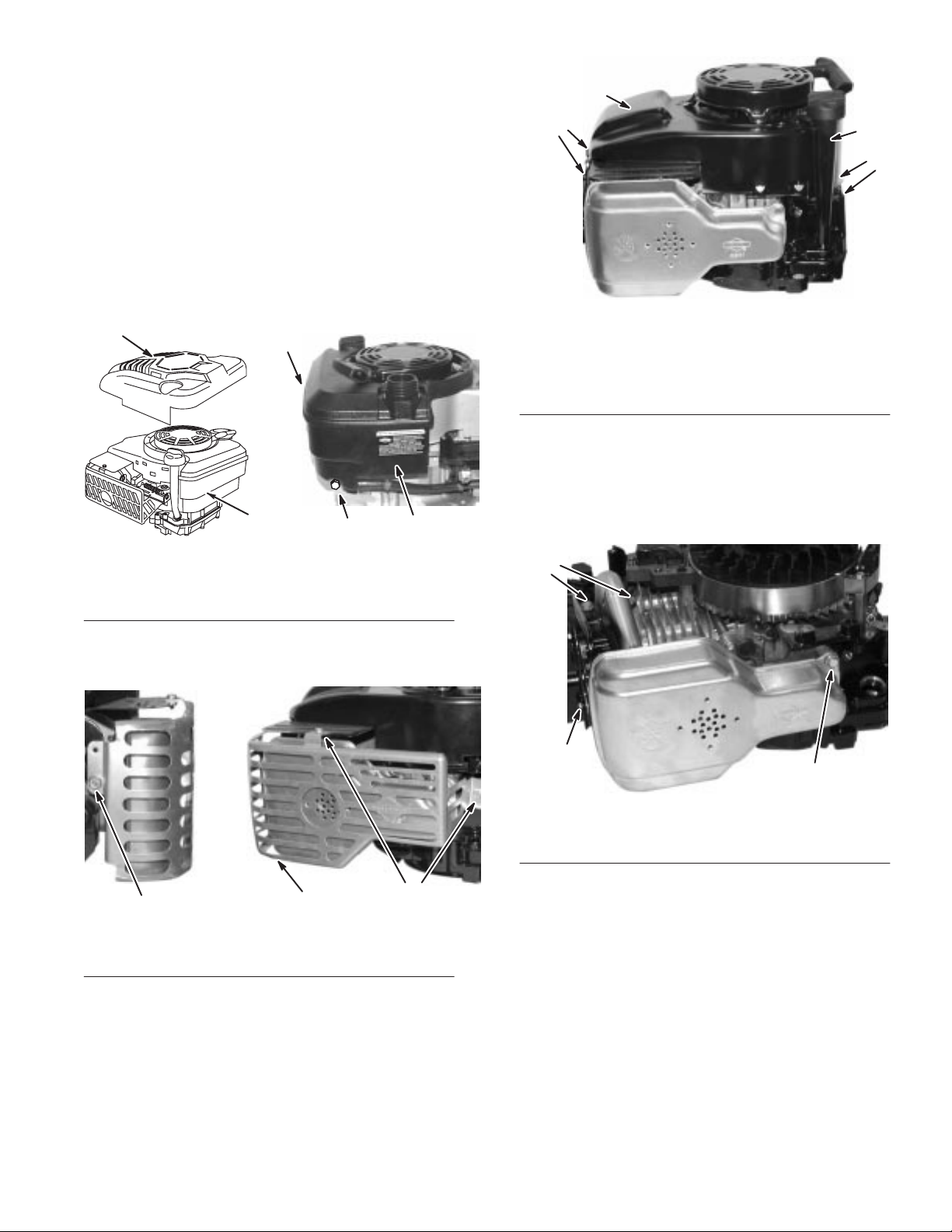
Muffler
2
Contents
Remove
Inspect Exhaust System59. . . . . . . . . . . . . . . . . . . . . . . . . . . .
Install Muf
Install Muf
Remove
1. Remove
1. Static
2.
Exhaust System59. . . . . . . . . . . . . . . . . . . . . . . . . . .
fler 60
. . . . . . . . . . . . . . . . . . . . . . . . . . . . . . . . . . .
fler Guard60. . . . . . . . . . . . . . . . . . . . . . . . . . . . . .
Exhaust System
Fig. 147.
1
Fig. 147
Fuel tank
air filter cover
– Removing Static Guard and Fuel T
guard
, static guard, and fuel tank,
3
2
3. Screw
3
2
ank
1
Fig. 149
1. Screws
2.
Blower housing and
rewind starter
5. Remove
cylinder head, one (1) screw holding muf
cylinder head, and one (1) screw holding muf
cylinder and remove muf
6.
Remove old muf
– Removing Dipstick and Oil Fill T
Blower Housing and Rewind Starter
(4)
two screws holding exhaust pipe flange to
fler gasket from cylinder head.
1
3.
Dipstick and oil fill tube
fler assembly
3
1
ube,
fler bracket to
fler to
, Fig. 150.
2. Remove
remove guard, Fig. 148.
Fig. 148
1. Screw 2. Muffler
3. Remove
4.
Remove blower housing and rewind starter
three (3) screws holding muf
1
– Removing Muffler Guard and Muffler
dipstick and oil fill tube.
2
fler guard and
1
guard
, Fig. 149.
1
1
Fig. 150
1. Screw
Inspect
Check
muf
cracked welds or breakage. Check muf
loose internal parts, or cracked welds. Replace any damaged
parts with new Original Equipment Parts.
Exhaust System
fler mounting bracket and/or muf
– Removing Muffler
fler adapters for
fler for split seams,
GTS 200
59
Muffler
Page 62

Install
Muffler
Install
Muffler Guard
1. Coat
2.
3.
1. Screw:
muf
fler mounting screws with V
Lubricant, Briggs & Stratton Part #93963.
Place new exhaust gasket on cylinder head and place
muf
fler flange on gasket.
Install two screws in muf
85 in. lbs. (10.0Nm), Fig. 151.
1
1
Fig. 151 – Installing Muffler
torque to 85 in. lbs (10.0Nm)
fler flange and torque to
alve Guide
1
1. Lightly
2.
3. T
4. T
5.
6.
7.
coat muf
Guide Lubricant, Briggs & Stratton Part #93963.
Place muf
to bracket screw to 85 in. lbs. (10.0Nm), Fig. 148.
orque muf
(6.0Nm).
orque muf
15 – 20 in. lbs. (2Nm).
Install blower housing as described in Rewind Starter
Page 37.
Install dipstick tube and dipstick.
Install fuel tank and static guard.
fler guard mounting screws with V
fler guard over muf
fler guard to cylinder screw to 50 in. lbs.
fler guard to blower housing screw to
fler and torque muf
alve
fler guard
,
4. Install
5.
screw in muf
torque to 85 in. lbs. (10.0Nm), Fig. 151.
Install screw in muf
85 in. lbs. (10.0Nm).
fler bracket to cylinder head and
fler to cylinder bracket and torque to
Muffler
60
GTS 200
 Loading...