

Page 1
TrimmerMountKit
ZMaster
ModelNo.145-3689
®
Professional2000SeriesRidingMower
Installation
LooseParts
Usethechartbelowtoverifythatallpartshavebeenshipped.
FormNo.3448-412RevA
InstallationInstructions
Description
Nopartsrequired
Rearbracket1
Nut(1/4inch)
Largebackerplate1
Largestclamp
Largest-clampbracket
Bolt(1/4x5/8inch)
Bolt(1/4x1-1/2inches)
Bolt(1/4x1-1/4inches)
Smallstclamp
Smallbackerplate
Carriagebolt(5/16x7/8inch)
Smallst-clampbracket
Trimmerplate1
Nut(5/16inch)
Channelbracket
Mountplate1
Knob1
Bolt(3/8x7/8inch)
Nut(3/8inch)
Carriagebolt(3/8x3inches)
Wide-angenut(3/8inch)
Rightpodsupportbracket—2021andnewer
machinesonly
Thread-formingscrew(3/8x1inch)—2021
andnewermachinesonly
Nopartsrequired
Qty.
Use
–
6
1
1
2
2
2
1
1
3
1
2
1
2
2
1
1
1
2
–
Preparethemachine.
Assemblethekit.
Mountthekittothemachine.
Secureatrimmertothemountassemblies.
©2021—TheT oro®Company
8111LyndaleAvenueSouth
Bloomington,MN55420
Registeratwww.T oro.com.
OriginalInstructions(EN)
PrintedintheUSA
AllRightsReserved
*3448-412*
Page 2
PreparingtheMachine
1.Parkthemachineonalevelsurface.
2.Movethemotion-controlleverstotheNEUTRAL-LOCKposition.
3.Engagetheparkingbrake.
4.Shutofftheengineandremovethekey .
AssemblingtheKit
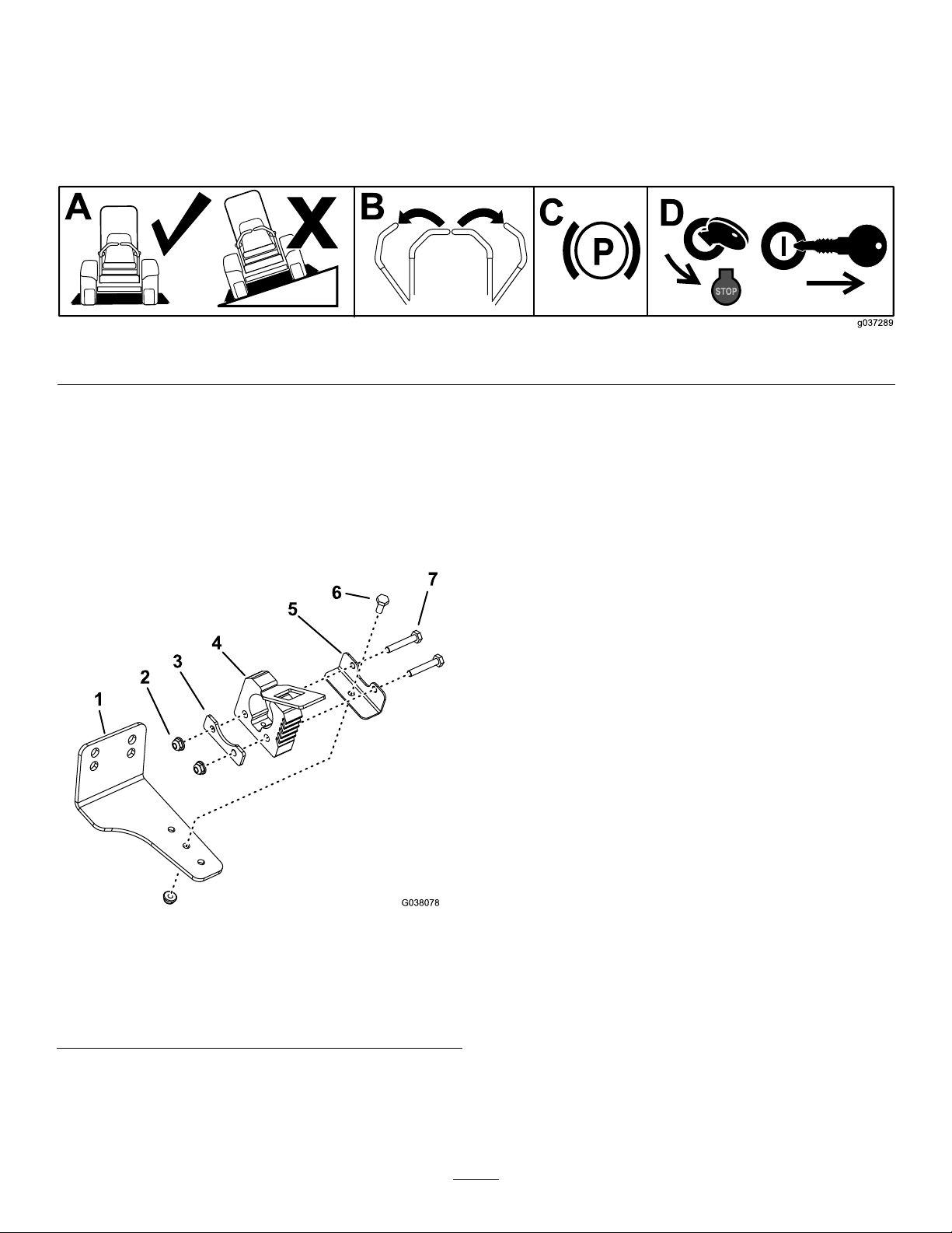
1.Assembletherearmountassembly(Figure2).
Note:Mountthelargest-clampbracketin
1ofthe3holestoallowclearancebetween
thetrimmerengineandthemachinewhenthe
trimmerismounted.
g037289
Figure1
Figure2
1.Rearbracket
2.Nut(1/4inch)6.Bolt(1/4x5/8inch)
3.Largebackerplate
4.Largestclamp
5.Largest-clampbracket
7.Bolt(1/4x1-1/2inches)
g038078
2
Page 3
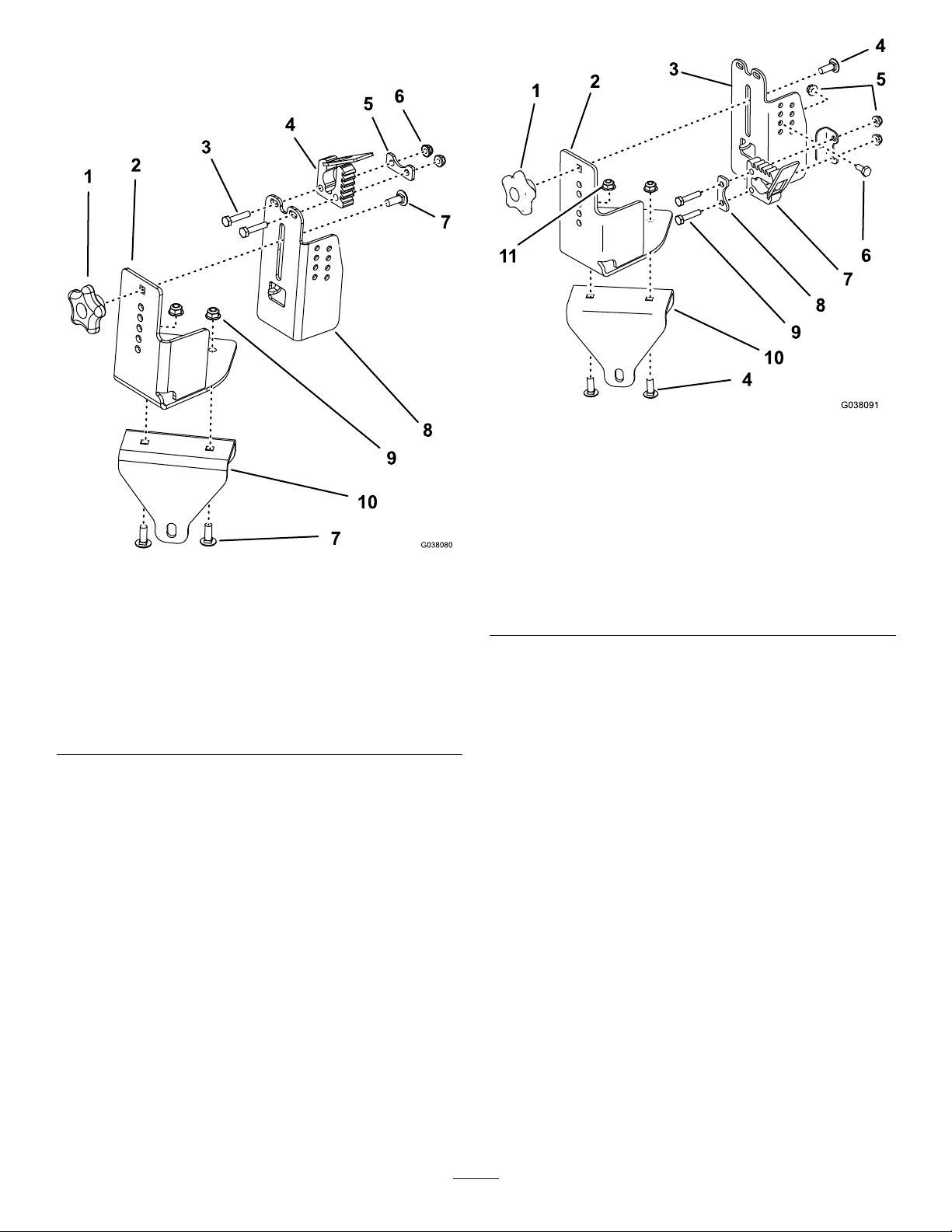
2.Assemblethefrontmountassemblyasshown
inFigure3orFigure4.
g038091
Figure4
AssemblyforTrimmerswithaCurvedShaft
Figure3
AssemblyforTrimmerswithaStraightShaft
1.Knob
2.Mountplate
3.Bolt(1/4x1-1/4inch)
4.Smallstclamp9.Nut(5/16inch)
5.Smallbackerplate10.Channelbracket
6.Nut(1/4inch)
7.Carriagebolt(5/16x7/8
inch)
8.Trimmerplate
1.Knob
2.Mountplate
3.Trimmerplate
g038080
4.Carriagebolt(5/16x7/8
inch)
5.Nut(1/4inch)11.Nut(5/16inch)
6.Bolt(1/4x5/8inch)
7.Smallstclamp
8.Smallbackerplate
9.Bolt(1/4x1-1/4inch)
10.Channelbracket
3
Page 4
MountingtheKittothe
Machine
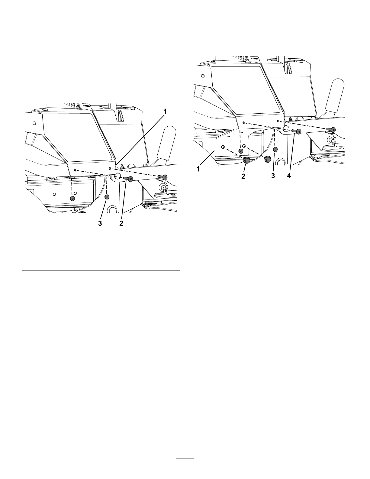
1.For2021andnewermachinesonly,dothe
following:
A.Removethe2torx-headscrews(1/4x
1-5/16inches)and2locknuts(1/4inch)
fromtherightpod(Figure5).
Retainthe2torx-headscrews(1/4x1-5/16
inches)and2locknuts(1/4inch).
B.Securetherightpodsupportbracketusing
the2newthread-formingscrews(3/8
x1inch)andthepreviouslyremoved2
torx-headscrews(1/4x1-5/16inches)and
2locknuts(1/4inch)asshowninFigure6.
g363212
Figure6
1.Rightpod
2.Torx-headscrew(1/4x
1-5/16inches)
Figure5
3.Locknut(1/4inch)
1.Rightpodsupportbracket3.Previouslyremoved
2.Thread-formingscrew(3/8
x1inch)
g363213
locknut(1/4inch)
4.Previouslyremoved
torx-headscrew(1/4x
1-5/16inches)
4
Page 5
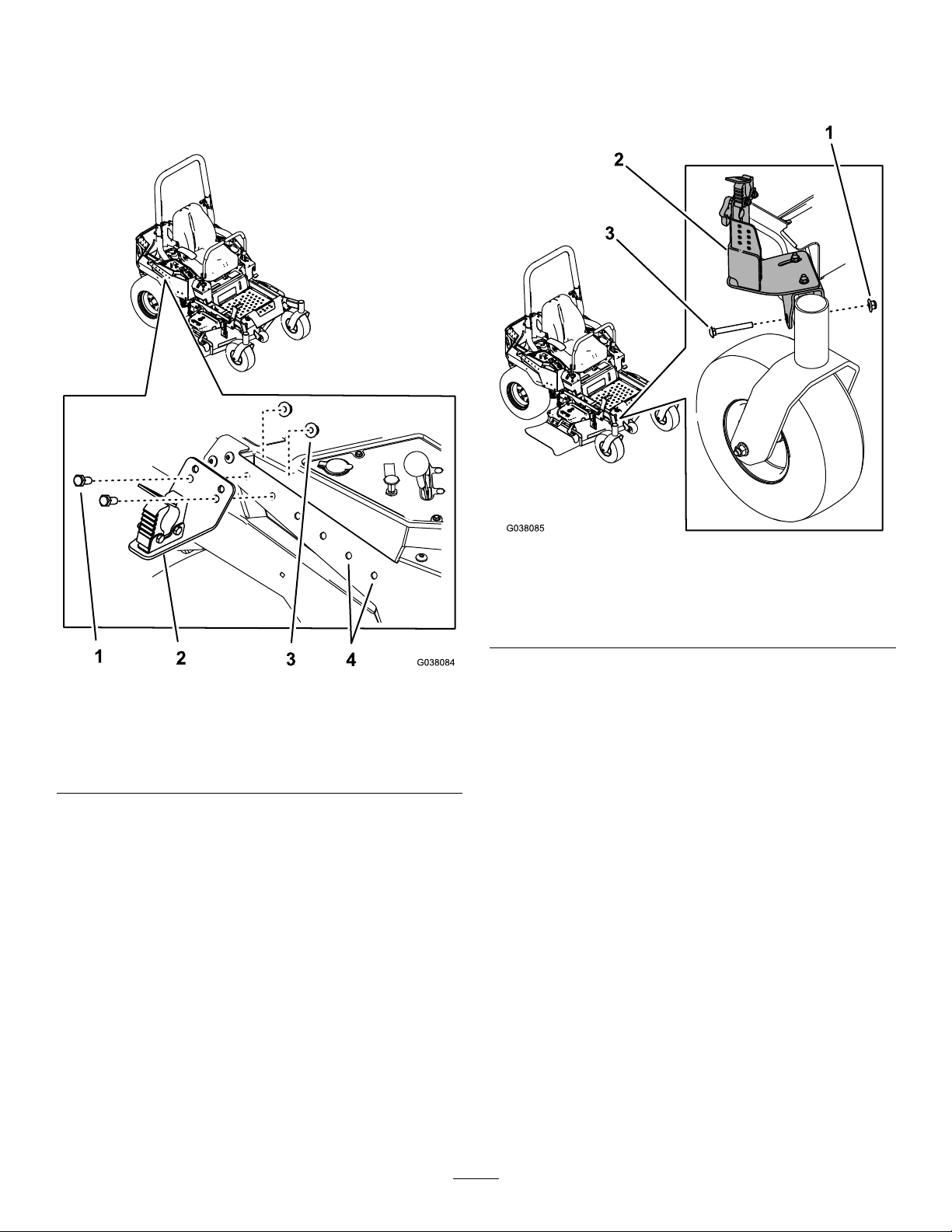
2.Installtherearmountassemblytotherightside
panelonthemachineusing2bolts(3/8x7/8
inch)and2nuts(3/8inch)asshowninFigure7.
Note:Usethe2frontholesifyouaremounting
acurvedtrimmer.
3.Installthefrontmountassemblyoverthe
frame,neartherightcasterwheel,usingthe
wide-angenut(3/8inch)andcarriagebolt(3/8
x3inches)asshowninFigure8.
Figure7
1.Bolt(3/8x7/8inch)3.Nut(3/8inch)
2.Rearmountassembly
4.Usetheseholesifyou
aremountingacurved
trimmer.
g038085
Figure8
1.Wide-angenut(3/8inch)3.Carriagebolt(3/8x3
inches)
2.Frontmountassembly
g038084
5
Page 6
SecuringaTrimmertothe
MountAssemblies
1.Securetherearendofthetrimmertotherear
mountassemblyusingthelargestclamp.
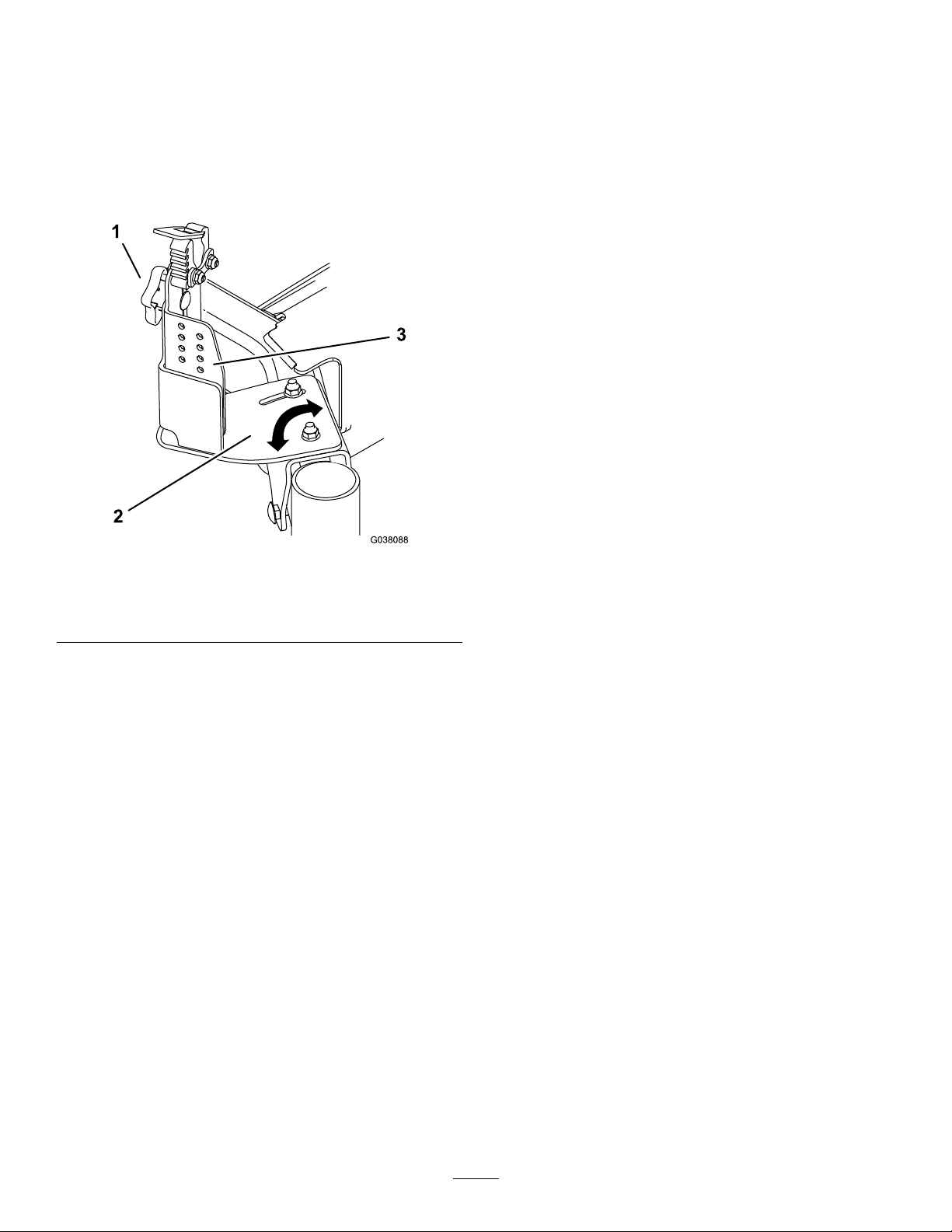
2.Loosentheboltssecuringthemountplatetothe
channelbracketinthefrontmountassembly
(Figure9).
Figure9
1.Knob3.Trimmerplate
2.Mountplate
3.Pivottheplatesothatthesmallstclamplines
upwiththetrimmer.Tightenthebolts.
4.Loosentheknobandraiseorlowerthetrimmer
plateasnecessary(Figure9).Tightentheknob.
5.Securethefrontendofthetrimmertothefront
mountassemblyusingthestclamp.
g038088
6
Page 7

Notes:
Page 8

 Loading...