

Page 1
Consumer Products
Power Max™
Snowthrower
Service Manual
Page 2

THIS PAGE INTENTIONALLY LEFT BLANK
Page 3

ABOUT THIS MANUAL
This service manual was written expressly for Toro service technicians. The Toro Company has made every effort to
make the information in this manual complete and correct.
Basic shop safety knowledge and mechanical/electrical skills are assumed. The Table of Contents lists the systems
and the related topics covered in this manual.
For information specifi c to the engines used on this unit, refer to the engine chapter of this book.
Power Max model years 2004 - 2005 are covered in this manual. The manual may also be specifi ed for use on later
model products.
We are hopeful that you will fi nd this manual a valuable addition to your service shop. If you have questions or
comments regarding this manual, please contact us at the following address:
The Toro Company
Consumer Service Department
8111 Lyndale Avenue South
Bloomington, MN 55420-1196
The Toro Company reserves the right to change product specifi cations or this manual without notice.
Copyright© All Rights Reserved
©2005 The Toro Company
Page 4

TABLE OF CONTENTS
SAFETY INFORMATION
Safety Information . . . . . . . . . . . . . . . . . . . . . . . . .
SPECIFICATIONS
Specifi cations . . . . . . . . . . . . . . . . . . . . . . . . . . .
Torque Specifi cations . . . . . . . . . . . . . . . . . . . . . . .
ENGINE
Service Information . . . . . . . . . . . . . . . . . . . . . . . .
Servicing the R tek Engine . . . . . . . . . . . . . . . . . . . . .
Primer Button . . . . . . . . . . . . . . . . . . . . . . . . . . .
Ignition Switch . . . . . . . . . . . . . . . . . . . . . . . . . . .
Fuel Tank, Fuel Line, Fuel Filter . . . . . . . . . . . . . . . . . .
Prime Line Routing . . . . . . . . . . . . . . . . . . . . . . . .
Engine Shroud Assembly . . . . . . . . . . . . . . . . . . . . .
1 - 1
2 - 1
2 - 3
3 - 1
3 - 1
3 - 2
3 - 2
3 - 3
3 - 3
3 - 3
CONTROLS
Quick Stick . . . . . . . . . . . . . . . . . . . . . . . . . . . . .
Operation . . . . . . . . . . . . . . . . . . . . . . . . .
Removal . . . . . . . . . . . . . . . . . . . . . . . . .
Disassembly . . . . . . . . . . . . . . . . . . . . . . .
Reassembly . . . . . . . . . . . . . . . . . . . . . . .
Installation . . . . . . . . . . . . . . . . . . . . . . . .
Control Interlock . . . . . . . . . . . . . . . . . . . . . . . . . .
Control Operation, Replacement & Adjustment . . . . . . . . . .
Defl ector Cable
Defl ector Cable Adjustment
Shift Lever . . . . . . . . . . . . . . . . . . . . . . . . . . . . .
Shift Rod Adjustment . . . . . . . . . . . . . . . . . . .
Auger Control . . . . . . . . . . . . . . . . . . . . . . .
Auger Cable Adjustment . . . . . . . . . . . . . . . . .
Auger Brake Adjustment . . . . . . . . . . . . . . . . .
Traction Control . . . . . . . . . . . . . . . . . . . . . .
Traction Cable Adjustment . . . . . . . . . . . . . . . .
Replace & Adjust Wheel Clutch Cables . . . . . . . . . . . . . .
4 - 1
4 - 1
4 - 1
4 - 3
4 - 4
4 - 5
4 - 5
4 - 7
4 - 7
4 - 8
4 - 8
4 - 8
4 - 9
4 - 9
4 - 10
4 - 10
4 - 11
4 - 11
ii Power Max Service Manual
Page 5

TABLE OF CONTENTS
TABLE OF CONTENTS
BELT REPLACEMENT
Auger Belt . . . . . . . . . . . . . . . . . . . . . . . . . . . . .
Traction Belt . . . . . . . . . . . . . . . . . . . . . . . . . . . .
AUGER HOUSING
Auger Housing Components . . . . . . . . . . . . . . . . . . . .
Skids . . . . . . . . . . . . . . . . . . . . . . . . . . . . . . . .
Scraper . . . . . . . . . . . . . . . . . . . . . . . . . . . . . .
Fixed Scraper . . . . . . . . . . . . . . . . . . . . . . .
Scraper Replacement . . . . . . . . . . . . . . . . . .
Adjusting the Skids and Scraper - Fixed . . . . . . . . .
Pivoting Scraper . . . . . . . . . . . . . . . . . . . . .
Scraper Replacement & Adjustment . . . . . . . . . . .
Adjusting the Skids and Scraper - Pivoting . . . . . . . .
5 - 1
5 - 2
6 - 1
6 - 1
6 - 1
6 - 1
6 - 1
6 - 2
6 - 2
6 - 2
6 - 3
AUGER GEARBOX
Auger Gearbox Removal Primary Method . . . . . . . . . . . . .
Separating the Auger & Traction Assemblies
Secondary Method . . . . . . . . . . . . . . . . . . . .
Gearbox Installation . . . . . . . . . . . . . . . . . . . . . . . .
Auger Gearbox Repair . . . . . . . . . . . . . . . . . . . . . . .
Lubrication . . . . . . . . . . . . . . . . . . . . . . . .
Gearbox Disassembly & Repair . . . . . . . . . . . . .
Failure Analysis . . . . . . . . . . . . . . . . . . . . . .
Gearbox Assembly . . . . . . . . . . . . . . . . . . . .
NON-WHEEL CLUTCH TRACTION DRIVE SYSTEM
General Description . . . . . . . . . . . . . . . . . . . . . . . .
Disassembly . . . . . . . . . . . . . . . . . . . . . . . . . . . .
Reassembly . . . . . . . . . . . . . . . . . . . . . . . . . . . .
WHEEL CLUTCH TRACTION DRIVE SYSTEM
General Description . . . . . . . . . . . . . . . . . . . . . . . .
Disassembly . . . . . . . . . . . . . . . . . . . . . . . . . . . .
Drive System Reassembly . . . . . . . . . . . . . . . . . . . . .
7 - 1
7 - 4
7 - 5
7 - 6
7 - 6
7 - 6
7 - 7
7 - 8
8 - 1
8 - 1
8 - 6
9 - 1
9 - 1
9 - 9
iiiPower Max Service Manual
Page 6

TABLE OF CONTENTS
TABLE OF CONTENTS
WHEEL CLUTCH TRACTION DRIVE SYSTEM (cont.)
Wheel Clutch Disassembly . . . . . . . . . . . . . . . . . . . .
Wheel Clutch Reassembly . . . . . . . . . . . . . . . . . . . . .
DISCHARGE CHUTE
Chute & Auger Cover Removal . . . . . . . . . . . . . . . . . .
Chute Gears . . . . . . . . . . . . . . . . . . . . . . . . . . . .
Operation . . . . . . . . . . . . . . . . . . . . . . . . .
Disassembly . . . . . . . . . . . . . . . . . . . . . . .
Assembly . . . . . . . . . . . . . . . . . . . . . . . . .
ELECTRICAL
Electric Start System . . . . . . . . . . . . . . . . . . . . . . . .
Lighting . . . . . . . . . . . . . . . . . . . . . . . . . . . . . .
Ignition Switch . . . . . . . . . . . . . . . . . . . . . . . . . . .
9 - 17
9 - 20
10 - 1
10 - 4
10 - 4
10 - 4
10 - 6
11 - 1
11 - 1
11 - 1
WHEELS and TIRES
Wheels . . . . . . . . . . . . . . . . . . . . . . . . . . . . . . .
Tires . . . . . . . . . . . . . . . . . . . . . . . . . . . . . . . .
12 - 1
12 - 1
iv Power Max Service Manual
Page 7

General Information
SAFETY INFORMATION
This symbol means WARNING or
PERSONAL SAFETY INSTRUCTION read the instruction because it has to do
with your safety. Failure to comply with
the instruction may result in personal
injury or even death.
This manual is intended as a service and repair manual
only. The safety instructions provided herein are for
troubleshooting, service, and repair of the Power Max™
snowthrower. The Power Max™ snowthrower operator’s
Think Safety First
Avoid unexpected starting of engine...
Always turn off the engine and disconnect the spark
plug wire(s) before cleaning, adjusting, or repair.
Avoid lacerations and amputations...
Stay clear of all moving parts whenever the engine is
running. Treat all normally moving parts as if they were
moving whenever the engine is running or has the
potential to start.
manual contains safety information and operating tips for
safe operating practices. Operator’s manuals are available through your parts source or:
The Toro Company
Publications Department
8111 Lyndale Avenue South
Bloomington, MN 55420
Avoid asphyxiation...
Never operate an engine in a confined area without
proper ventilation.
Avoid injury due to inferior parts...
Use only original equipment parts to ensure that
important safety criteria are met.
Avoid injury to bystanders...
Avoid burns...
Do not touch the engine, muffler, or other components
which may increase in temperature during operation,
while the unit is running or shortly after it has been
running.
Avoid fires and explosions...
Avoid spilling fuel and never smoke while working with
any type of fuel or lubricant. Wipe up any spilled fuel or
oil immediately. Never remove the fuel cap or add fuel
when the engine is running. Always use approved,
labeled containers for storing or transporting fuel and
lubricants.
Always clear the area of bystanders before starting or
testing powered equipment.
Avoid injury due to projectiles...
Always clear the area of sticks, rocks, or any other
debris that could be picked up and thrown by the
powered equipment.
Avoid modifications...
Never alter or modify any part unless it is a factory
approved procedure.
1-1Power Max Service Manual
Page 8

THIS PAGE INTENTIONALLY LEFT BLANK
1-2 Power Max Service Manual
Page 9

SPECIFICATIONS
Engine RPM
2-cycle 4,000 +250 -250 RPM
4-cycle 3,300 +150 -150 RPM
Auger
26” 26” (66cm) Wide & 21.5” (54.6cm) High
28” 28” (71cm) Wide & 21.5” (54.6cm) High
Auger Speed 123 RPM @ engine RPM listed above
Impeller 12” Dia. (30.5cm)
Impeller Speed 1228 RPM @ engine RPM listed above
Chute Rotation 200 degrees
Defl ector tilt angle 70 degrees
Tires Semi pneumatic 15x500x6
Pressure 17-20 psi ( 116-137kPa)
Ground speeds
Forward 0.7, 1.1, 1.5, 1.9, 2.3, 2.7 mph
(1.1, 1.8, 2.4, 3.0, 3.7, 4.3 kph)
Reverse 1.0 & 1.6 mph
(1.6 & 2.5 kph)
Height 44.5” (113cm) Approx.
Overall Width 27.5” (69.8cm) and 29.5” (74.9cm)
Length 62” (157cm)
Weight 724= 210 lbs (462kg) 826= 238 lbs (526kg)
828 & 1028= 245 lbs (539kg) 1128= 253 lbs (556kg)
Fuel Capacity
2 cycle engine 1.46 US qts (1.38l)
4 cycle engine 4 US qts (3.8l)
Fuel/oil
2-cycle Fuel Unleaded regular grade gasoline mixed at a ratio of 50:1
2.6 oz. (80ml) oil / 1 US gallon (3.8l) gasoline.
2-cycle Required oil Toro 2 cycle oil or any 2-cycle oil that is NMMA TCW3
(ISO E GD) certifi ed as an acceptable substitute.
4-cycle Fuel Unleaded regular grade gasoline (do not mix with oil).
4-cycle Oil automotive detergent oil with a service classifi cation of
SH or higher Maximum capacity 26 oz. (770ml)
The recommended weight varies with the outside temperature
For Temps Above 32
For Temps Between 00 F and
320 F ( -180 C to 00 C)
For Temps Below 00 F (-180 C) use SAE 0W30
Auger Gearbox lubricant* SAE 90 gear oil with a rating of GL5 or higher
*A multi weight may be used such as 85-120 as long as it meets the GL rating. Place the
unit on level ground and fi ll to the fi ll/check plug. Maximum capacity 4 oz (118ml).
0
F (00 C) use SAE 30W
use SAE 5W30 or SAE 10W
2-1Power Max Service Manual
Page 10

SPECIFICATIONS
The following parts should be lightly coated with an anti-seize
compound when assembling after making repairs.
1. The impeller shaft, before installing the impeller pulley.
2. The engine crankshaft before installing the engine pulley.
3. The full length of the auger shaft before installing the augers.
4. The outer 5” (12.7cm) of the axle before installing the wheels.
Accessories
• Drift Breaker
• Tire Chains
• Snow Cab
• Weight Kit (Required with Cab)
2-2 Power Max Service Manual
Page 11
SPECIFICATIONS
Torque Specifications
Recommended fastener torque values are listed in the
following tables. For critical applications, as
determined by Toro, either the recommended torque or
a torque that is unique to the application is clearly
identified and specified in the service manual.
These torque specifications for the installation and
tightening of fasteners shall apply to all fasteners which
do not have a specific requirement identified in the
service manual. The following factors shall be
considered when applying torque: cleanliness of the
fastener, use of a thread sealant (Loctite), degree of
lubrication on the fastener, presence of a prevailing
torque feature, hardness of the surface underneath of
the fastener’s head, or similar condition which affects
the installation.
As noted in the following tables, torque values should
be reduced by 25% for lubricated fasteners to
achieve the similar stress as a dry fastener. Torque
values may also have to be reduced when the fastener
is threaded into aluminum or brass. The specific
torque value should be determined based on the
aluminum or brass material strength, fastener size,
length of thread engagement, etc.
Fastener Identification
Inch Series Bolts and Screws
(A) Grade 1
(B) Grade 5
Figure 1
(C) Grade 8
The standard method of verifying torque shall be
performed by marking a line on the fastener (head or
nut) and mating part, then back off fastener 1/4 of a
turn. Measure the torque required to tighten the
fastener until the lines match up.
Figure 2
Metric Bolts and Screws
(A) Class 8.8 (B) Class 10.9
2-3Power Max Service Manual
Page 12

SPECIFICATIONS
Standard Torque for Dry, Zinc Plated, and Steel Fasteners (Inch Series)
Grade 1, 5, &
Thread Size
# 6 - 32 UNC
# 6 - 40 UNF 17 ± 2 190 ± 20 25 ± 2 280 ± 20
# 8 - 32 UNC
# 8 - 36 UNF 31 ± 3 350 ± 30 43 ± 4 31 ± 3
# 10 - 24 UNC
#10 - 32 UNF 48 ± 4 540 ± 45 68 ± 6 765 ± 70
1/4 - 20 UNC 48 ± 7 53 ± 7 599 ± 79 100 ± 10 1125 ± 100 140 ± 15 1580 ± 170
1/4 - 28 UNF 53 ± 7 65 ± 10 734 ± 113 115 ± 10 1300 ± 100 160 ± 15 1800 ± 170
5/16 - 18 UNC 115 ± 15 105 ± 17 1186 ± 169 200 ± 25 2250 ± 280 300 ± 30 3390 ± 340
5/16 - 24 UNF 138 ± 17 128 ± 17 1446 ± 192 225 ± 25 2540 ± 280 325 ± 30 3670 ± 340
3/8 - 16 UNC 16 ± 2 16 ± 2 22 ± 3 30 ± 3 41 ± 4 43 ± 4 58 ± 5
3/8 - 24 UNF 17 ± 2 18 ± 2 24 ± 3 35 ± 3 47 ± 4 50 ± 4 68 ± 5
7/16 - 14 UNC 27 ± 3 27 ± 3 37 ± 4 50 ± 5 68 ± 7 70 ± 7 68 ± 9
7/16 - 20 UNF 29 ± 3 29 ± 3 39 ± 4 55 ± 5 75 ± 7 77 ± 7 104 ± 9
1/2 - 13 UNC 30 ± 3 48 ± 7 65 ± 9 75 ± 8 102 ± 11 105 ± 10 142 ± 14
1/2 - 20 UNF 32 ± 3 53 ± 7 72 ± 9 85 ± 8 115 ± 11 120 ± 10 163 ± 14
5/8 - 11 UNC 65 ± 10 88 ± 12 119 ± 16 150 ± 15 203 ± 20 210 ± 20 285 ± 27
5/8 - 18 UNF 75 ± 10 95 ± 15 129 ± 20 170 ± 15 230 ± 20 240 ± 20 325 ± 27
3/4 - 10 UNC 93 ± 12 140 ± 20 190 ± 27 265 ± 25 359 ± 34 374 ± 35 508 ± 47
3/4 - 16 UNF 115 ± 15 165 ± 25 224 ± 34 300 ± 25 407 ± 34 420 ± 35 569 ± 47
7/8 - 9 UNC 140 ± 20 225 ± 25 305 ± 34 430 ± 45 583 ± 61 600 ± 60 813 ± 81
7/8 - 14 UNF 155 ± 25 260 ± 30 353 ± 41 475 ± 45 644 ± 61 660 ± 60 895 ± 81
8 with Thin
Height Nuts
In-lb In-lb N-cm In-lb N-cm In-lb N-cm
10 ± 2 13 ± 2 147 ± 23
13 ± 2 25 ± 5 282 ± 30
18 ± 2 30 ± 5 339 ± 56
ft-lb ft-lb N-m ft-lb N-m ft-lb N-m
SAE Grade 1 Bolts, Screws,
Studs, & Sems with Regular
Height Nuts (SAE J995
Grade 2 or Stronger Nuts)
SAE Grade 5 Bolts, Screws,
Studs, & Sems with Regular
Height Nuts (SAE J995
Grade 2 or Stronger Nuts)
15 ± 2 170 ± 20 23 ± 2 260 ± 20
29 ± 3 330 ± 30 41 ± 4 460 ± 45
42 ± 4 475 ± 45 60 ± 6 674 ± 70
SAE Grade 8 Bolts, Screws,
Studs, & Sems with Regular
Height Nuts (SAE J995
Grade 2 or Stronger Nuts)
Note: Reduce torque values listed in the table above
by 25% for lubricated fasteners. Lubricated fasteners
are defined as threads coated with a lubricant such as
oil, graphite, or thread sealant such as Loctite.
Note: The nominal torque values listed above for
Grade 5 and 8 fasteners are based on 75% of the
minimum proof load specified in SAE J429. The
tolerance is approximately
value. Thin height nuts include jam nuts.
± 10% of the nominal torque
Note: Torque values may have to be reduced when
installing fasteners into threaded aluminum or brass.
The specific torque value should be determined based
on the fastener size, the aluminum or base material
strength, length of thread engagement, etc.
2-4 Power Max Service Manual
Page 13

SPECIFICATIONS
Standard Torque for Dry, Zinc, and Steel Fasteners (Metric Fasteners)
Class 8.8 Bolts, Screws, and Studs with
Thread Size
M5 X 0.8 57 ± 5 in-lb 640 ± 60 N-cm 78 ± 7 in-lb 885 ± 80 N-cm
M6 X 1.0 96 ± 9 in-lb 1018 ± 100 N-cm 133 ± 13 in-lb 1500 ± 150 N-cm
M8 X 1.25 19 ± 2 ft-lb 26 ± 3 N-m 27 ± 2 ft-lb 36 ± 3 N-m
M10 X 1.5 38 ± 4 ft-lb 52 ± 5 N-m 53 ± 5 ft-lb 72 ± 7 N-m
M12 X 1.75 66 ± 7 ft-lb 90 ± 10 N-m 92 ± 9 ft-lb 125 ± 12 N-m
M16 X 2.0 166 ± 15 ft-lb 225 ± 20 N-m 229 ± 22 ft-lb 310 ± 30 N-m
M20 X 2.5 325 ± 33 ft-lb 440 ± 45 N-m 450 ± 37 ft-lb 610 ± 50 N-m
Note: Reduce torque values listed in the table above
by 25% for lubricated fasteners. Lubricated fasteners
are defined as threads coated with a lubricant such as
oil, graphite, or thread sealant such as Loctite.
Note: Torque values may have to be reduced when
installing fasteners into threaded aluminum or brass.
The specific torque value should be determined based
on the fastener size, the aluminum or base material
strength, length of thread engagement, etc.
Regular Height Nuts
(Class 8 or Strong Nuts)
Note: The nominal torque values listed above are
based on 75% of the minimum proof load specified in
SAE J1199. The tolerance is approximately
the nominal torque value. Thin height nuts include jam nuts.
Class 10.9 Bolts, Screws, and Studs with
Regular Height Nuts (
Class 10 or Strong Nuts)
± 10% of
2-5Power Max Service Manual
Page 14

SPECIFICATIONS
Other Torque Specifications
SAE Grade 8 Steel Set Screws
Recommended Torque
Thread Size
Square Head Hex Socket
1/4 - 20 UNC 140 ± 20 in-lb 73 ± 12 in-lb
5/16 - 18 UNC 215 ± 35 in-lb 145 ± 20 in-lb
3/8 - 16 UNC 35 ± 10 ft-lb 18 ± 3 ft-lb
1/2 - 13 UNC 75 ± 15 ft-lb 50 ± 10 ft-lb
Thread Cutting Screws
(Zinc Plated Steel)
Typ e 1 , Ty pe 23, or Type F
Thread Size Baseline Torque*
No. 6 - 32 UNC 20 ± 5 in-lb
Wheel Bolts and Lug Nuts
Thread Size Recommended Torque**
7/16 - 20 UNF
Grade 5
1/2 - 20 UNF
Grade 5
M12 X 1.25
Class 8.8
M12 X 1.5
Class 8.8
65 ± 10 ft-lb 88 ± 14 N-m
80 ± 10 ft-lb 108 ± 14 N-m
80 ± 10 ft-lb 108 ± 14 N-m
80 ± 10 ft-lb 108 ± 14 N-m
** For steel wheels and non-lubricated fasteners.
Thread Cutting Screws
(Zinc Plated Steel)
Thread
Size
No. 6 18 20 20 ± 5 in-lb
Threads per Inch
Baseline Torque*
Type A Typ e B
No. 8 - 32 UNC 30 ± 5 in-lb
No.10 - 24 UNC 38 ± 7 in-lb
1/4 - 20 UNC 85 ± 15 in-lb
5/16 - 18 UNC 110 ± 20 in-lb
3/8 - 16 UNC 200 ± 100 in-lb
Conversion Factors
in-lb X 11.2985 - N-cm
ft-lb X 1.3558 = N-m
No. 8 15 18 30 ± 5 in-lb
No. 10 12 16 38 ± 7 in-lb
No. 12 11 14 85 ± 15 in-lb
* Hole size, material strength, material thickness and
finish must be considered when determining specific
torque values. All torque values are based on nonlubricated fasteners.
N-cm X - 0.08851 = in-lb
N-cm X 0.73776 - ft-lb
2-6 Power Max Service Manual
Page 15

SPECIFICATIONS
Equivalents and Conversions
Decimal and Millimeter Equivalents
Fractions Decimals mm Fractions Decimals mm
1/64 0.015625 0.397 33/64 0.515625 13.097
1/32 0.03125 0.794 16/32 0.53125 13.484
3/64 0.046875 1.191 35/64 0.546875 13.891
1/16 0.0625 1.588 9/16 0.5625 14.288
5/64 0.078125 1.984 37/64 0.578125 14.684
3/32 0.9375 2.381 19/32 0.59375 15.081
1/8 0.1250 3.175 5/8 0.6250 15.875
9/64 0.140625 3.572 41/64 0.640625 16.272
5/32 0.15625 3.969 21/32 0.65625 16.669
11/64 0.171875 4.366 43/64 0.671875 17.066
3/16 0.1875 4.762 11/16 0.6875 17.462
13/64 0.203125 5.159 45/64 0.703125 17.859
7/32 0.21875 5.556 23/32 0.71875 18.256
15/64 0.234375 5.953 47/64 0.734375 18.653
1/4 0.2500 6.350 3/4 0.7500 19.050
17/64 0.265625 6.747 49/64 0.765625 19.447
9/32 0.28125 7.144 25/32 0.78125 19.844
19/64 0.296875 7.541 51/64 0.796875 20.241
5/16 0.3125 7.541 13/16 0.8125 20.638
21/64 0.328125 8.334 53/64 0.828125 21.034
11/32 0.34375 8.731 27/32 0.84375 21.431
23/64 0.359375 9.128 55/64 0.859375 21.828
3/8 0.3750 9.525 7/8 0.8750 22.225
25/64 0.390625 9.922 57/64 0.890625 22.622
13/32 0.40625 10.319 29/32 0.90625 23.019
27/64 0.421875 10.716 59/64 0.921875 23.416
7/16 0.4375 11.112 15/16 0.9375 23.812
29/64 0.453125 11.509 61/64 0.953125 24.209
15/32 0.46875 11.906 31/32 0.96875 24.606
31/64 0.484375 12.303 63/64 0.984375 25.003
1/2 0.5000 12.700 1 1.000 25.400
1 mm = 0.03937 in. 0.001 in. = 0.0254 mm
2-7Power Max Service Manual
Page 16

SPECIFICATIONS
U.S. to Metric Conversions
To Conve r t Into Multiply By
Miles
Yar ds
Linear
Measurement
Area
Volume
Weight
Pressure
Work
Liquid Volume
Liquid Flows
Tempera t u re
Feet
Feet
Inches
Inches
Inches
Square Miles
Square Feet
Square Inches
Acre
Cubic Yards
Cubic Feet
Cubic Inches
Tons (Short)
Pounds
Ounces
Pounds/Sq. In. Kilopascal
Foot-pounds
Foot-pounds
Inch-pounds
Quarts
Gallons
Gallons/Minute Liters/Minute
Fahrenheit Celsius
Kilometers
Meters
Meters
Centimeters
Meters
Centimeters
Millimeters
Square Kilometers
Square Meters
Square Centimeters
Hectare
Cubic Meters
Cubic Meters
Cubic Centimeters
Metric Tons
Kilograms
Grams
Newton-Meters
Kilogram-Meters
Kilogram-Centimeters
Liters
Liters
1.609
0.9144
0.3048
30.48
0.0254
2.54
25.4
2.59
0.0929
6.452
0.4047
0.7646
0.02832
16.39
0.9078
0.4536
28.3495
6.895
1.356
0.1383
1.152144
0.9463
3.785
3.785
1. Subtract 32°
2. Multiply by 5/9
2-8 Power Max Service Manual
Page 17
ENGINE
Service Information
The Power Max snowthrowers have both 2-cycle and
4-cycle engines. The process for obtaining parts and
service information is different between them.
4-Cycle Engine
All 4 cycle models use a Tecumseh Snow King engine.
Service information can be obtained through Tecumseh
at the following address.
Tecumseh Products Company
Engine and Transmission Group
Service Division
900 North Street
Grafton, WI 53024
Phone 262-377-2700
2-Cycle Engine
All 2-cycle models use the Toro R tek engine. Service
is handled through the Toro system. Detailed engine
repair information is available in the “E” Engine Service
Manual, Form No. 492-0647.
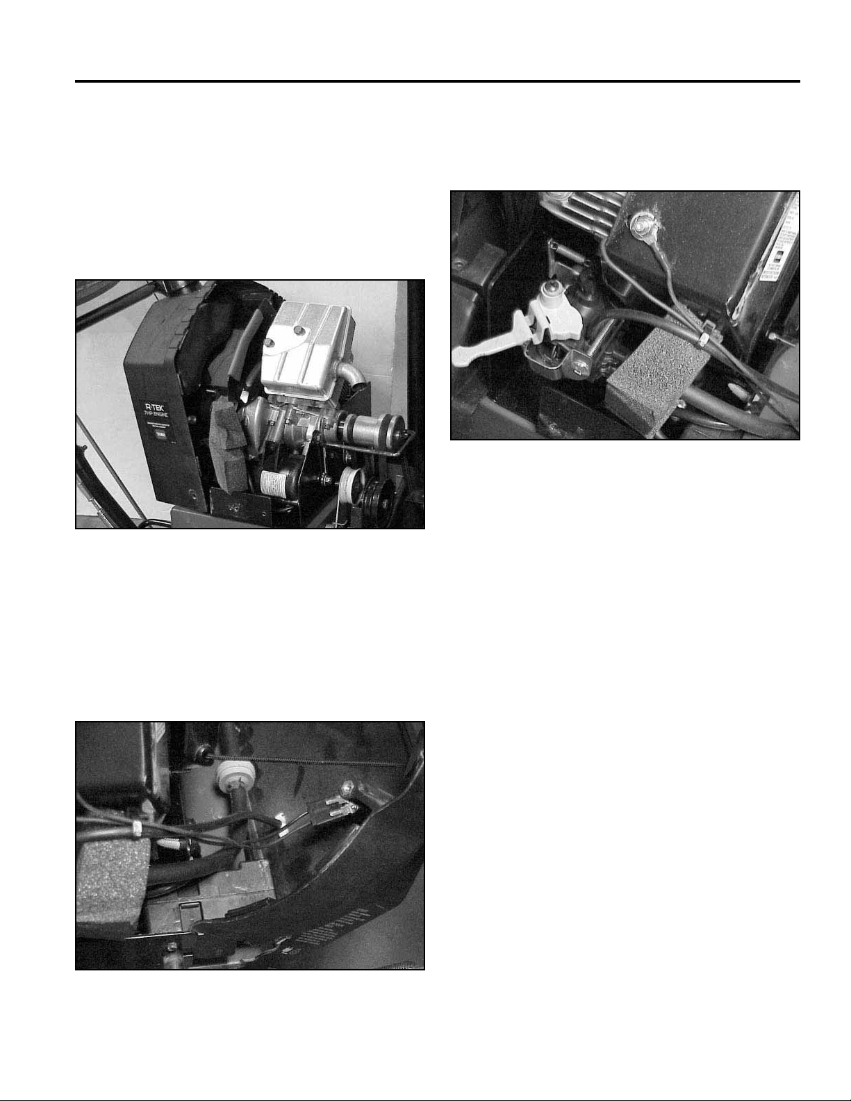
Servicing the R tek Engine
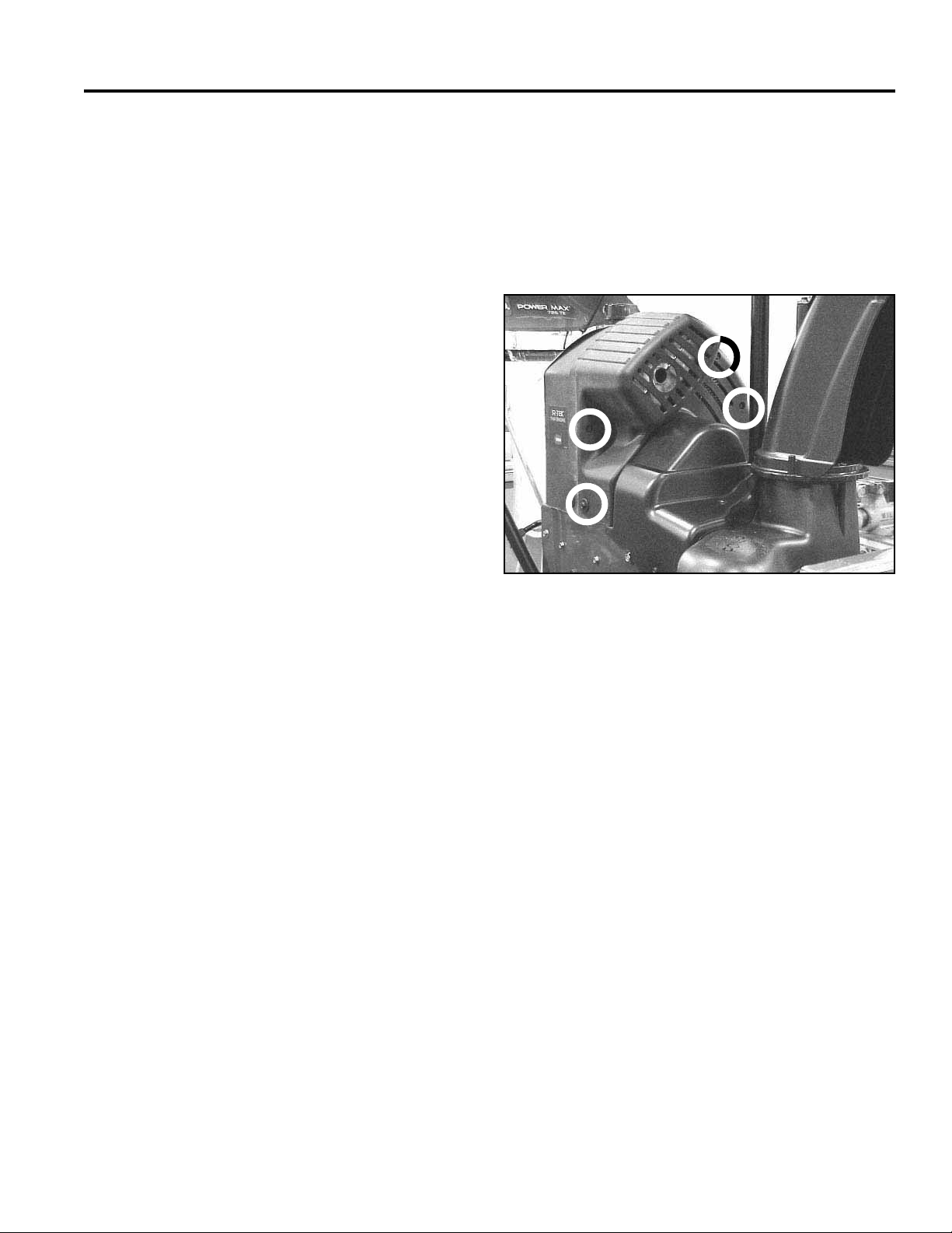
Use the following process to service the R tek engine.
1. Remove the three screws across the front of the
engine shroud and 2 screws on each side where the
front and rear shroud meet (Fig. 003).
Fig 003 MVC-001X
2. Remove 4 screws securing the belt covers; remove
the belt covers. (Reassembly will be much easier if
the belt covers have been removed.
3-1Power Max Service Manual
Page 18
ENGINE
3. Pull the front shroud forward and up to remove. Slide
the rear cover to the rear and rotate it clockwise to
slip over the electric starter button and extension
cord plug located in the left rear corner (Fig. 004).
Fig 004 MVC-900XB
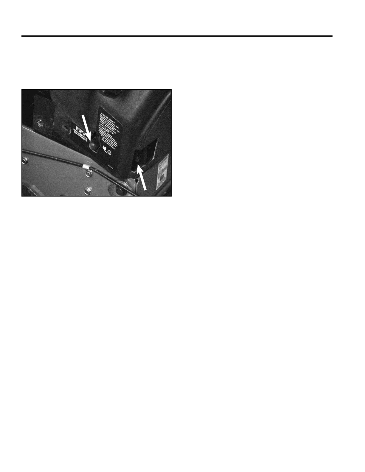
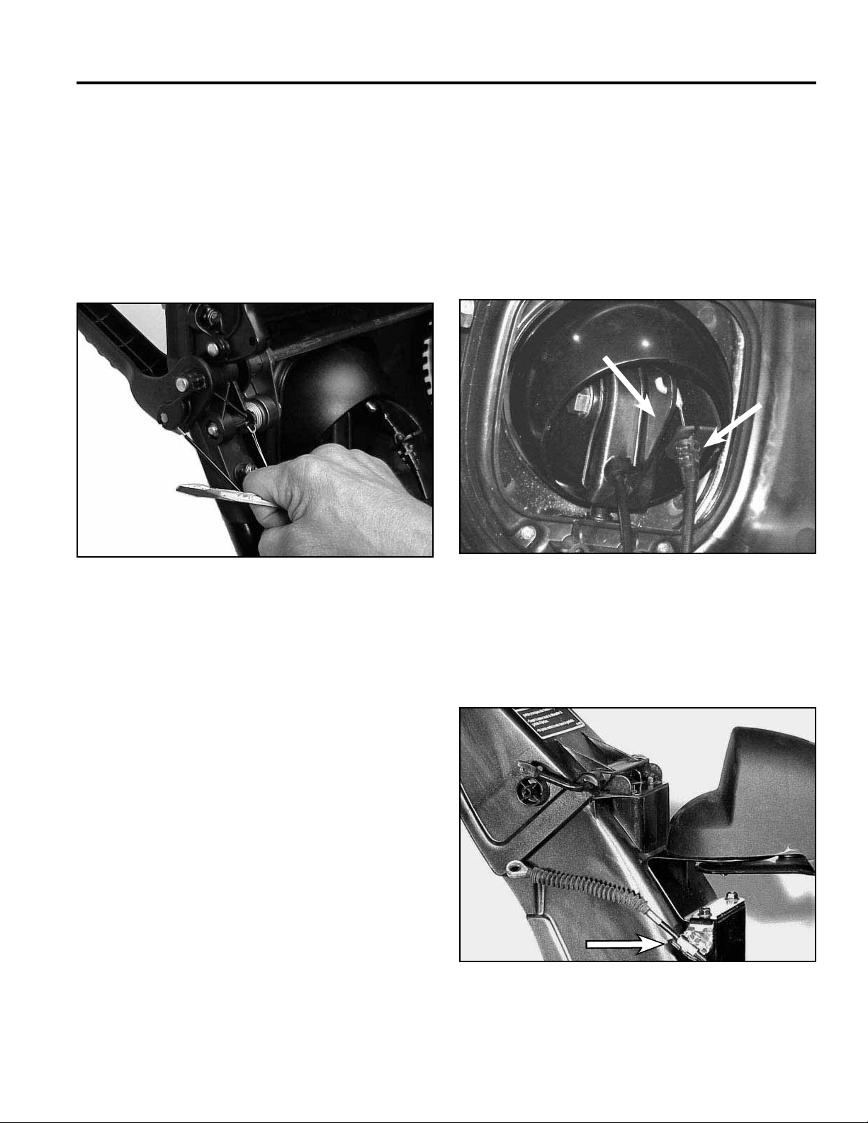
Primer Button
When depressed the primer button pressurizes the
carburetor bowl. Fuel is forced up the main tube to
the carburetor venturi. This line and button are the
atmospheric vent for the carburetor bowl. If the line
is kinked or the vent hole in the bulb is plugged, the
carburetor may fl ood.
To remove the primer button, pull the primer line off the
stem and compress the tabs. The primer will push out to
the rear (Fig. 005).
Fig 005 MVC-865XA
Ignition Switch
To remove the ignition switch, pull the wire harness off
the switch terminals. The switch is a snap in type. To
remove the switch, depress the ears on the switch body
(Fig. 006) and push the switch out through the rear of
the shroud. Switch troubleshooting is provided in the
electrical section.
Fig 006 MVC-863XA
3-2 Power Max Service Manual
Page 19
ENGINE
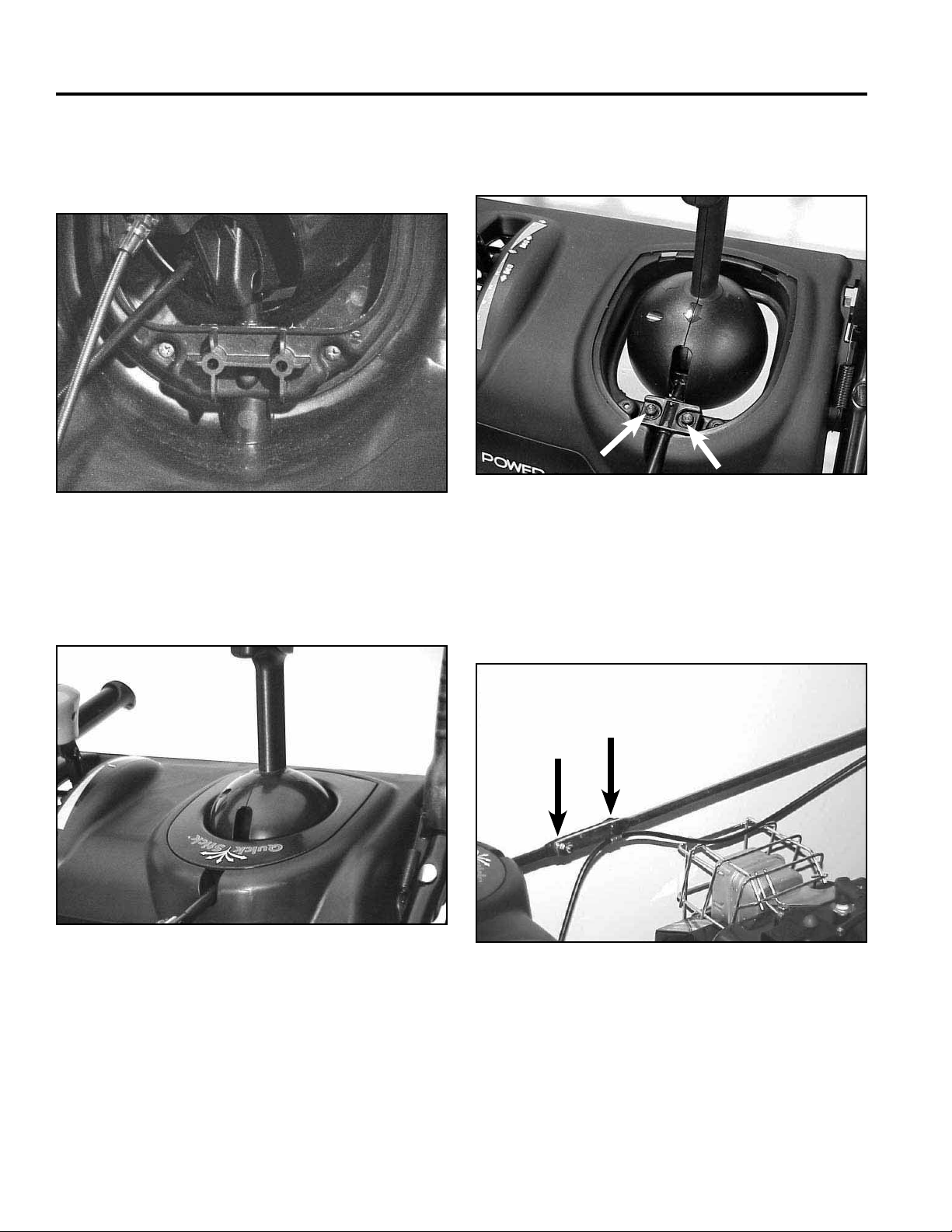
Fuel Tank, Fuel Line and Fuel Filter
To remove the fuel tank, unscrew the gas cap, slip the
tank out of the shroud and install the cap. If there is
fuel in the tank, clamp the line, or drain the tank into a
suitable container. Remove the fuel line and fuel fi lter.
The tank is held in place by the bracket and shroud
surrounding it (Fig. 007).
Fig 007 MVC-000
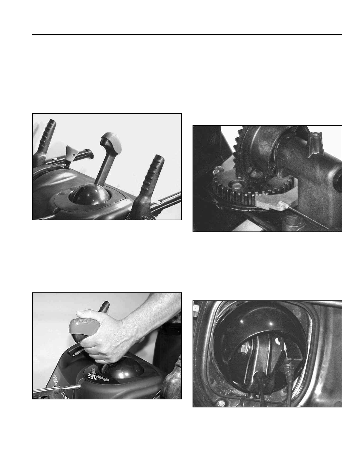
Primer Line Routing
The primer line connects to the back side of the primer
then is routed over the fuel line, over the foam block
(Fig. 008).
It should be gathered and secured to the ignition switch
wires. It then goes down to the primer fi tting on top of the
carburetor (Fig. 009).
Fig 009 MVC-866XA
Engine Shroud Assembly
1. Ensure the ignition switch is in place and the wire
harness is plugged in, the primer line is attached to
the primer and the primer body is secure in its slot,
and the fuel tank, fuel line and fi lter are properly
installed.
Fig 008 MVC-865XA
3-3Power Max Service Manual
Page 20
ENGINE
2. Begin in the left rear corner; slip the shroud over
the electric start button and the plug terminal for the
extension cord (Fig. 010). Then rotate the shroud
clockwise into place.
Fig 010 MVC-893XC
3. While the engine shroud is still loose, install both belt
covers. Then install and secure the front and rear
engine covers to each other and to the chassis.
3-4 Power Max Service Manual
Page 21
CONTROLS
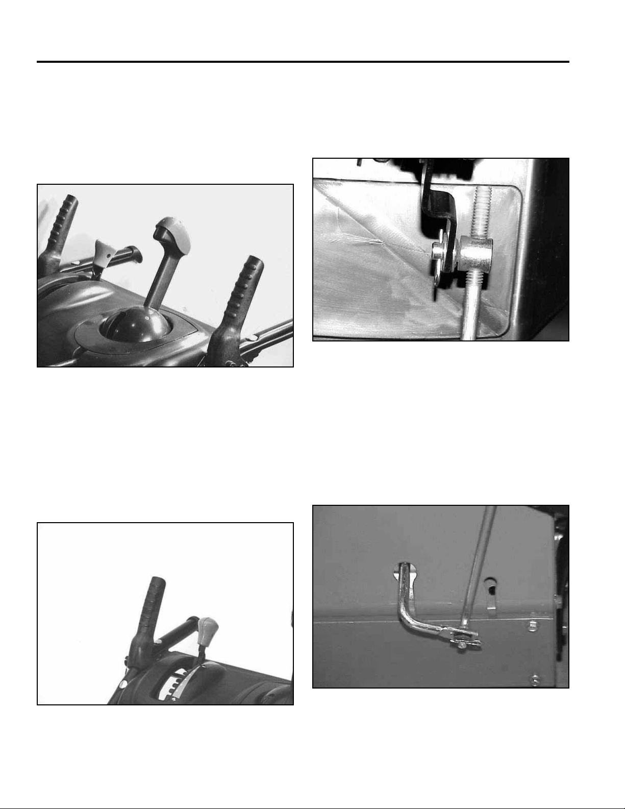
QUICK STICK
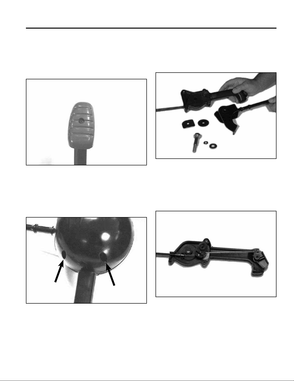
Operation
The Quick Stick is a single lever control for chute sideto-side movement and vertical movement of the defl ector
(Fig. 011).
The defl ector up and down motion is unlatched inside
the quick stick itself and a cable controls the up and
down motion.
Removing the cover just behind the chute allows access
to the chute rotation gears and chute latch (Fig. 013).
Since these gears are plastic they do not require
lubrication. The latch cable adjustment is covered in the
control adjustment section.
Fig 011 MVC-775X
When the operator places their hand on the stick the
cover is depressed, which draws a cable to unlatch the
chute (Fig. 012). Side to side motion rotates the rod and
gear and causes the chute to pivot side to side.
Fig 013 MVC-772X
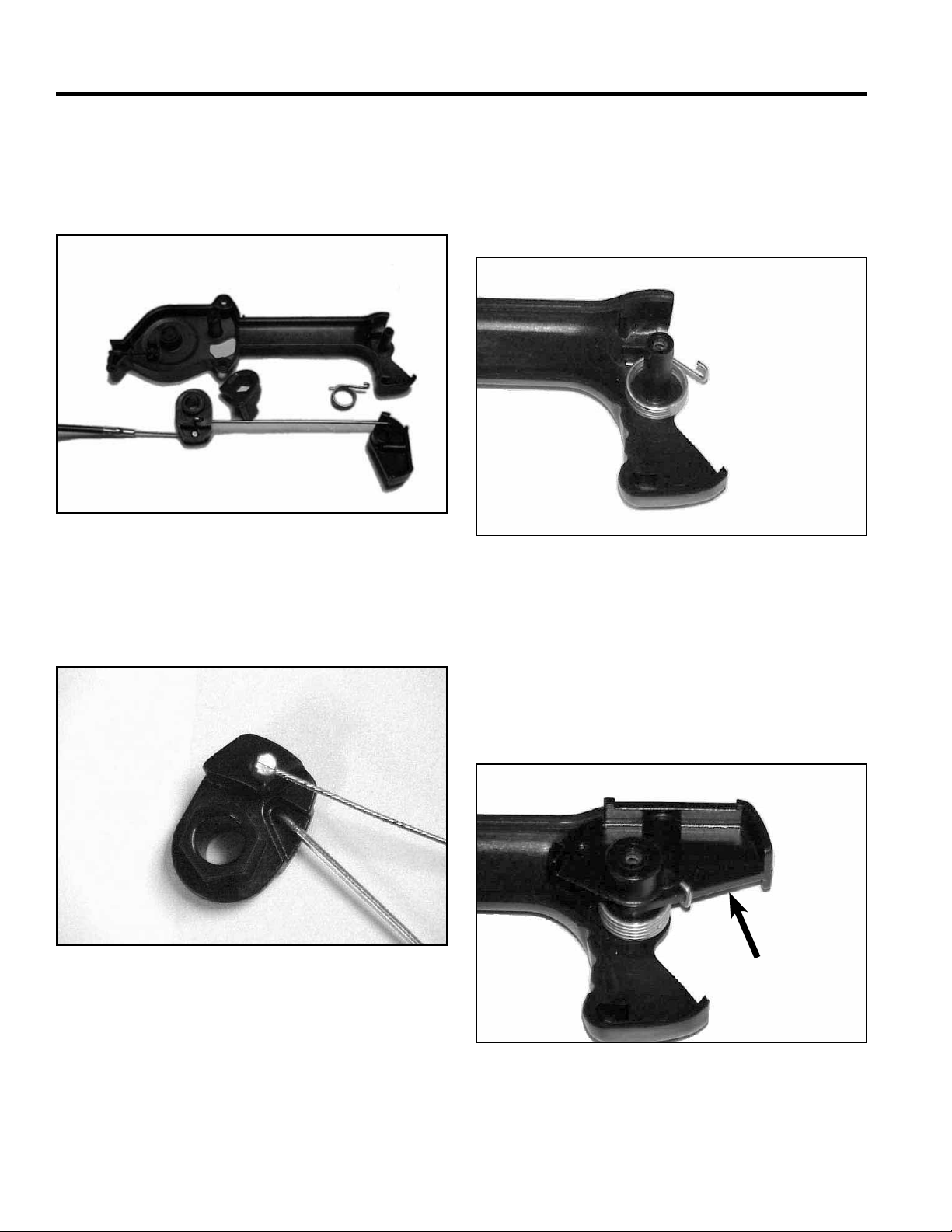
Removal
1. To remove the Quick Stick, unhook the Z bend and
disconnect the defl ector cable from the underside of
the Quick Stick (Fig. 014).
Fig 012 MVC-039F
Fig 014 MVC-870XA
4-1Power Max Service Manual
Page 22
CONTROLS
2. On the underside of the control panel, remove the
two screws holding the Quick Stick cover in place
(Fig. 015).
Fig 015 MVC-1869X
3. Lift the front cover and pull forward to release the
latch tabs on the rear. Set the cover aside (Fig. 016).
4. Remove the two screws that retain the rod support
to the control panel (Fig. 017).
Fig 017 MVC-819X
5. Remove the two carriage bolts and nuts on the chute
control rod and lift the Quick Stick out of the control
panel. Note the location of the cable clamp, as it is
necessary for latch cable function (Fig. 018).
Fig 016 MVC-902X
Fig 018 MVC-725F
4-2 Power Max Service Manual
Page 23
CONTROLS
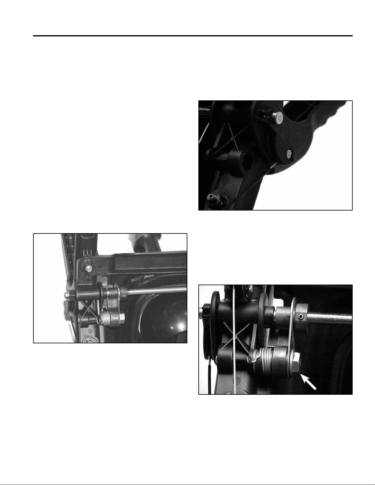
Disassembly
1. To begin disassembly of the Quick Stick, remove the
screw retaining the blue lever cap and remove the
cap (Fig. 019).
Fig 019 MVC-546F
3. Remove the locknut and fl at washer from the
shoulder bolt. Slide the chute control rod off and
remove the rubber washer and friction plate
(Fig. 021).
Fig 021 MVC-832S
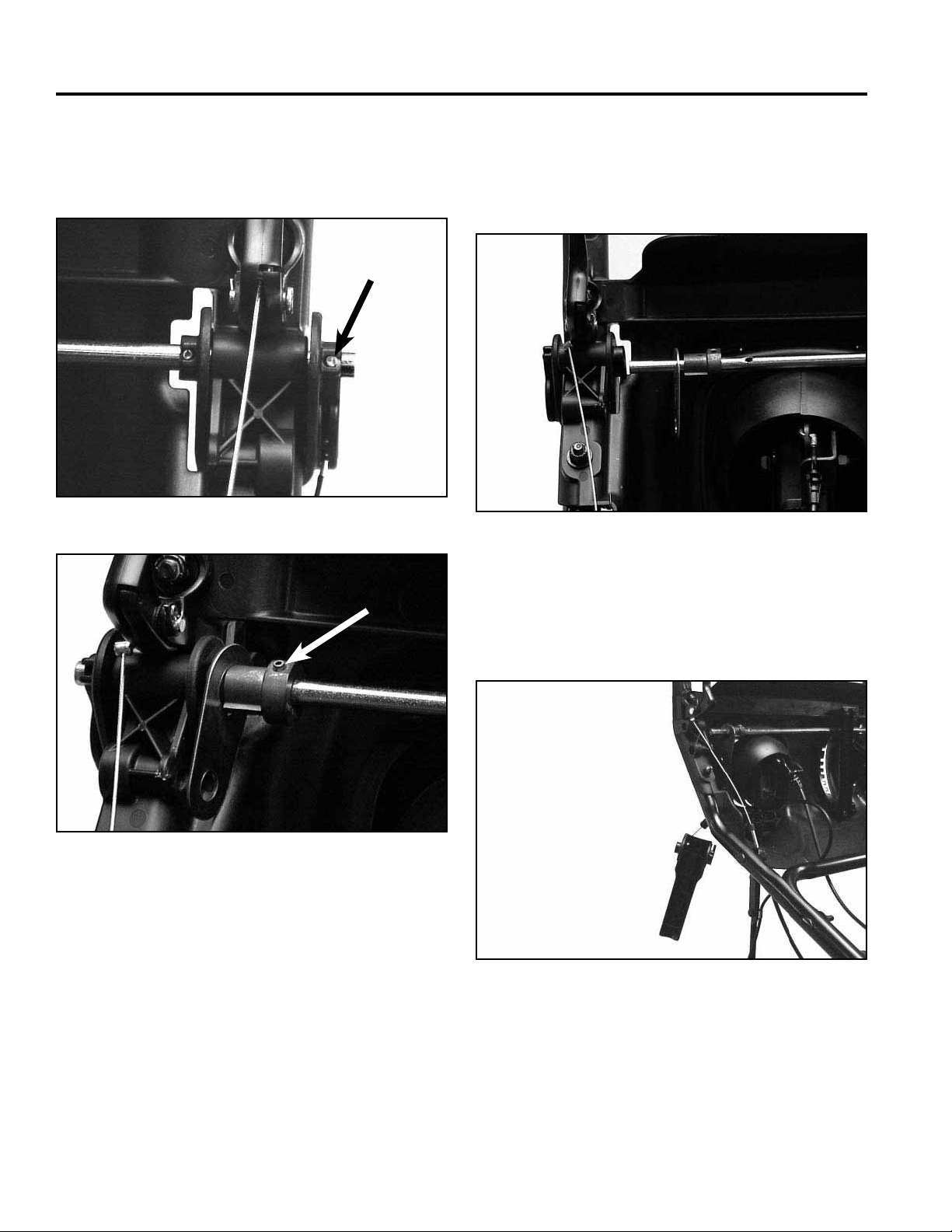
2. Remove the two screws on the right hand side of the
chute control cover (the part that looks like a ball).
Remove both halves and set aside (Fig. 020).
Fig 020 MVC-547F
4. Hold the Quick Stick so the three screws holding
the handle halves are facing up. Remove the three
screws and lift off the top handle half (Fig. 022).
Fig 022 MVC-8335X
4-3Power Max Service Manual
Page 24
CONTROLS
5. Lift the metal latch pawl off the hex on the cable
lever. Lift out the latch trigger and spring. Note the
orientation of the pawl to the lever for reassembly
(Fig. 023).
Fig 023 MVC-837X
Reassembly
1. Begin assembly by dropping the latch spring over
the boss. The straight end of the spring should be
down with the hooked end up (Fig. 025).
Fig 025 MVC-759F
6. Rotate the cable until the barrel fi tting slides off the
cable lever (Fig. 024).
Fig 024 MVC-554F
2. Slide the latch trigger over the boss until it is fully
seated, making sure that the stop on the trigger
lever is above the stop on the quick lever, as shown.
While holding the trigger lever in place, rotate the
hooked end of the spring until it hooks under the
front edge of the trigger lever as shown (Fig. 026).
A
Fig 026 MVC-758F
A. Latch trigger
4-4 Power Max Service Manual
Page 25
CONTROLS
3. Reverse the disassembly process for the remainder
of the assembly.
Installation
Reverse the removal process for installation.
Note: The cable clamp must be installed on the
chute control rod or the cable latch will not
function.
CONTROL INTERLOCK
For operator convenience there is an interlock between
the auger and traction lever. Once both are engaged
you only need to hold the auger lever. This allows a
free hand to change chute direction without having to
stop. The latch mechanism is located under the dash
(Fig. 027).
Disassembly
1. Disconnect the auger and traction cables from the
levers. If this is a wheel clutch model, disconnect the
wheel clutch cables (Fig. 028).
Fig 028 MVC-171X
Fig 027 MVC-872X
2. Remove the Shoulder Screw under the left handgrip
(Fig. 029). When it is removed the Lockout Latch,
Torsion Spring, Flat Washer, and Locknut will drop
out.
Fig 029 MVC-167X
4-5Power Max Service Manual
Page 26
CONTROLS
3. To remove the lockout rod, go to the right hand end.
There are 2 roll pins on the right side (Fig. 030) and
one in the lockout cam on the left (Fig. 031).
Fig 030 MVC-169X
4. Once they are driven out the lockout rod can be
moved to the side and removed (Fig. 032). The
lockout link can now be removed from the lockout
rod.
Fig 032 MVC-172X
Fig 031 MVC-170X
5. Since the auger and traction levers pivot on the
lockout rod this is the method required to replace the
levers (Fig. 033).
Fig 033 MVC-174X
Note: Steps 1 and 2 above do not need to be done
in that order. In fact you can remove the rod
without removing the shoulder bolt and vice
versa.
4-6 Power Max Service Manual
Page 27
CONTROLS
Assembly
Reverse the above process for assembly.
Note the spring on the lockout latch. The end with the
slight bend goes behind the lockout latch and the hooked
end goes over the small tab. It is easiest to install the
latch mechanism then hook the end of the spring with a
wire and pull it into place (Fig. 034).
CONTROL OPERATION,
REPLACEMENT, AND ADJUSTMENT
Defl ector Cable
1. To remove the defl ector cable, depress the tabs that
retain the cable in the bracket, under the control
panel. Disconnect the Z bend on the end (Fig. 035).
Fig 034 MVC-176X
Fig 035 MVC-870X
2. Remove the cable clamp and disconnect the cable
end from the defl ector. Reverse this process to
install a new cable (Fig. 036).
Fig 036 MVC-882X
4-7Power Max Service Manual
Page 28
CONTROLS
Defl ector Cable Adjustment
Make sure the Quick Stick is in the maximum rear
position and centered (Fig. 037); ensure the defl ector
is in the full upward position. Draw the slack out of the
cable and secure the clamp (Fig. 036).
Fig 037 MVC-775X
Shift Rod Adjustment
1. The adjustment point is a trunion on the upper end
of the shift rod (Fig. 039).
Fig 039 MVC-561F
SHIFT LEVER
The shift lever on the control panel is connected to the
friction wheel in the traction drive by a shift rod. Moving
the shift lever moves the friction wheel to change wheel
direction and speed (Fig. 038).
2. Pull the shift rod and arm upward as far as they will
go. With the shift lever in R2, adjust the trunion to
take the slack out and resecure (Fig. 040).
Note: Excessive slack in the linkage may cause the
drive to be in reverse when shifted into fi rst
gear.
Fig 040 MVC-560F
Fig 038 MVC-901XA
4-8 Power Max Service Manual
Page 29
CONTROLS
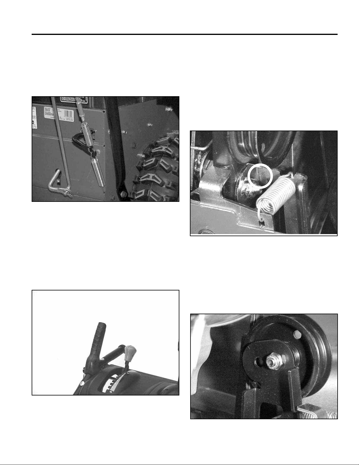
Auger Control
The bail on the right hand handle is the auger control.
Squeeze the bail and the cable causes an idler to pivot
tensioning the auger belt (Fig. 041).
Fig 041 MVC-816X
2. Loosen the jam nut. The cable is adjusted using the
turnbuckle on the lower end of the auger cable.
Note: When rotating the turnbuckle, hold the cable
so it does not twist (Fig. 041).
3. Remove the right side belt cover. Adjust the
turnbuckle until there is a 1/16” (1.5mm) gap
between the stop and the auger clutch assembly.
Secure the jam nut on the turnbuckle (Fig. 043).
Auger Cable Adjustment
1. The auger cable adjustment should be checked after
the fi rst 2 hours of use and annually thereafter. To
begin, ensure the auger lever is in the full up position
(Fig. 042).
Fig 042 MVC-901XA
Fig 043 MVC-876X
Beginning with 2005 production there are two holes
in the idler arm (Fig. 044). The idler pulley is initially
installed in the outer hole. If necessary, the idler
can be moved to achieve the correct tension. 2004
models have only one hole in the idler.
Fig 044 MVC-016X
4-9Power Max Service Manual
Page 30

CONTROLS
To determine if the pulley should be moved, proceed
as follows: remove the right side belt cover. With the
engine off, engage the auger lever. If there is more than
1” 2.5cm) gap between the idler arm and the stop, move
the pulley to the inner hole (Fig. 045). If the gap is less
than 1” (2.5cm) keep the pulley in the outer hole.
Note: If you move the idler pulley, it will be
necessary to readjust both the auger brake
and the auger cable.
If adjustment is necessary, loosen the bolt through the
welded washer/nut and rotate the washer/nut to achieve
the gap. Secure the bolt (Fig. 046).
Fig 046 MVC-876X
Traction Control
Fig 045 MVC-892XA
Auger Brake Adjustment
1. As the auger cable is adjusted to maintain proper
belt tension, the idler will move towards the brake
arm. The gap between the idler arm and brake arm
may be reduced. Periodically, verify the gap as
follows to make sure the brake engages properly.
2. Remove the belt cover and check the gap between
the welded washer/nut assembly and the brake arm
tab.
The gap should be .100” (2.5mm)
The traction bail is on the left handle and when
squeezed engages the wheel drive system (Fig. 047).
Fig 047 MVC-899XA
4-10 Power Max Service Manual
Page 31

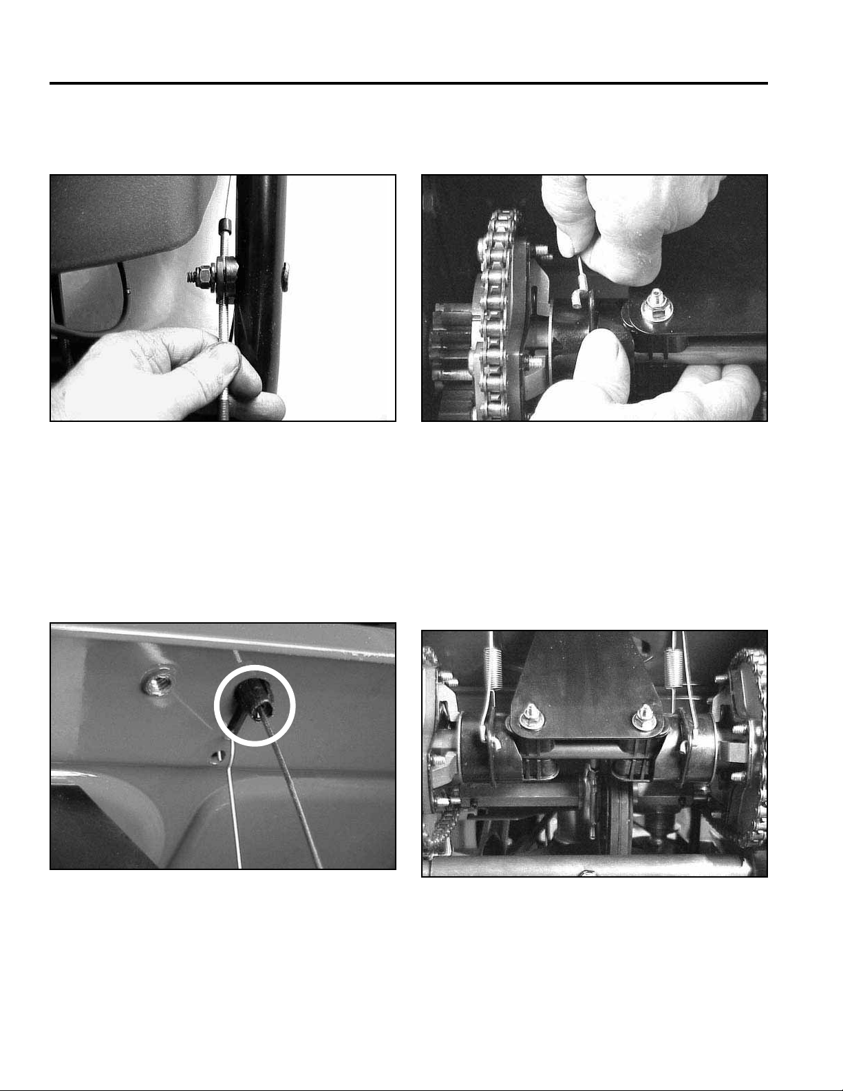
Traction Cable Adjustment
1. The traction lever should be in the full upright
position with some slack in the traction cable to
begin adjustment (Fig. 047).
2. Adjust using the turnbuckle; hold the cable to
prevent twisting (Fig. 048).
CONTROLS
Fig 049 MVC-895X
REPLACE AND ADJUST WHEEL
CLUTCH CABLES (wheel clutch
models only)
Fig 048 MVC-894X
3. Locate the traction rod on the left side just below the
belt cover.
Adjust the cable turnbuckle until there is a slight gap
between the end of the rod and the front of the slot
(maximum 1/16” [1.5mm]). Secure the jam nut on
the turnbuckle (Fig. 049). The left hand belt cover
has been removed only for clarity.
Clutch Cable Replacement
1. To replace the clutch cables, drain the fuel tank and
stand the machine on the auger. Remove both lower
covers (Fig. 050). The wheels and the bottom cover
can also be removed if desired.
Fig 050 MVC-892X
4-11Power Max Service Manual
Page 32
CONTROLS
2. Remove nut and washer that attach the cable clamp
to the handle (Fig. 051).
Fig 051 MVC-889XYL
3. Slip the cable Z bend out of the wheel clutch lever
on the handle.
4. Reach under the shift plate and compress the small
ears on the cable fi tting (Fig. 052). The cable fi tting
can then be pushed out of the shift plate.
5. Disconnect the lower end of the cable from the shift
collar (Fig. 053).
Fig 053 MVC-898XB
Assembly
1. Feed the lower end of the cable through the shift
plate and snap the cable into the plate. Install the
lower end of the cable into the shift collar outside in,
as shown (Fig. 054).
Fig 052 MVC-899X
4-12 Power Max Service Manual
Fig 054 MVC-878XYZ1
Page 33

CONTROLS
2. Hook the upper end of the cable to the wheel clutch
lever and install the cable clamp to the handle.
Go to Adjusting Clutch Cables for the adjustment
procedure before securing the clamp.
3. Install the covers and test run the unit.
Adjusting Clutch Cables
1. Loosen the cable clamp nut (Fig. 055).
2. Pull the cable jacket down gently until the wheel
clutch lever is down and the slack is out of the
cable, and then tighten the cable clamp nut securely
(Fig. 056).
Fig 056 MVC-889XYL
Fig 055 MVC-889XYL
3. Squeeze the lever fully, and then check the gap
between the bottom of the handle and the wheel
clutch lever end.
Note: The gap should be approximately 1/4 inch
(6mm). If it is greater, loosen the cable clamp
nut, slide the cable jacket up slightly, tighten
the cable clamp nut, and check the gap again.
Repeat steps for other cable (Fig. 057).
Fig 057 MVC-891XLY
4-13Power Max Service Manual
Page 34

THIS PAGE INTENTIONALLY LEFT BLANK
4-14 Power Max Service Manual
Page 35

BELT REPLACEMENT
AUGER BELT
1. To replace the belts begin by removing both belt
covers (Fig. 058). (On 2-cycle models only, remove
3 screws holding the front half of the engine shroud
to the chassis and the rear shroud. The belt cover
slides under the front of the engine shroud so this
will make belt cover removal much easier.)
3. Remove the brake assembly for more working room.
Disconnect the spring, then remove the two bolts
through the side plate (Fig. 060).
B
A
C
Fig 060 MVC-1883X
A. Spring C. Bolts
B. Brake Assembly
Fig 058 MVC-006XB
2. Remove the belt guide. Be careful to avoid bending
the guide (Fig. 059).
Fig 059 MVC-007F
4. The brake assembly can be lifted out of the chassis
(Fig. 061).
A
Fig 061 MVC-067X
A. Brake Assembly
5-1Power Max Service Manual
Page 36

BELT REPLACEMENT
(Fig. 064)
5. Remove the bolt securing the engine pulley to
the crankshaft. If necessary, you can hold the
hub between the pulley and engine to keep the
crankshaft from turning. Remove the pulley fl ange
and the auger belt from the crankshaft (Fig. 062).
Fig 062 MVC-747X
TRACTION BELT
To replace the traction belt, perform steps 1-5 above to
remove the auger belt. Then proceed with the following
steps.
1. Slip the center section of the crankshaft pulley off
the crankshaft
(Fig. 064).
6. The auger belt can now be removed from the
impeller pulley (Fig. 063).
Fig 063 MVC-886XB
Reverse the process to install a new belt. Use Loctite
242 and torque the engine pulley to 29 ft-lbs. (39.3 Nm)
Fig 064 MVC-887X
2. On the left side of the machine, remove the hairpin
cotter from the speed control link (Fig. 065).
Fig 065 MVC-897X
5-2 Power Max Service Manual
Page 37

BELT REPLACEMENT
3. Move the link to the side and let it rest in the saddle
provided (Fig. 066). Reach down alongside the link
and remove the belt from the lower pulley. Then
remove the belt from the crankshaft pulley.
Fig 066 MVC-888XB
Belt Adjustment
Belt adjustments are made by adjusting the control
cables. See the Controls Section for the procedure.
4. Reverse the process to install a new belt.
5. Check for proper clearance between the belt and
belt guide. Engage the auger belt and look between
the belt and belt guide on the left side. There should
be about 1/8” (3.2mm) gap (Fig. 067). Tighten the
belt guide mounting bolts.
Fig 067 MVC-822X
5-3Power Max Service Manual
Page 38

THIS PAGE INTENTIONALLY LEFT BLANK
5-4 Power Max Service Manual
Page 39

AUGER HOUSING
AUGER HOUSING COMPONENTS SCRAPER
The Power Max snow throwers are offered in two widths:
26” and 28” (66cm and 71cm). The augers, auger shaft,
housing, and scrapers are made in both widths, but all
other auger components are the same. The auger case
halves, gears, impeller and impeller shaft, chute, etc. are
interchangeable.
Removal of the auger and traction system components
from the auger housing is covered in the Auger Gearbox
Section and in the two traction drive systems sections
(non-wheel clutch and wheel clutch).
SKIDS
The skids are located on each side of the auger. The
skids are intended to be the component that touches
the ground and supports the auger. They are also the
means to adjust the auger height for different conditions
(Fig. 068).
The scraper is a replaceable surface attached to the
leading edge of the auger housing. It is a wear part and
will need to be replaced periodically in the life of the
machine. There are two types of scrapers, fi xed and
pivoting.
Fixed Scraper
Because the fi xed scraper is bolted solidly to the auger
housing it is intended to be raised slightly off the ground
to minimize catching on pavement cracks and solid
objects. The amount that it should be raised depends on
how rough the ground is. The scraper is adjustable as
the mounting holes are slotted (Fig. 069).
Fig 068 MVC-769X
See the scraper adjustment procedure to adjust the
skids.
Note: The skids are reversible. When one side
becomes worn out, remove the skid and turn
it over for a new surface.
Fig 069 MVC-896X
Scraper Replacement
The scraper is attached with fi ve carriage head bolts with
locknuts. Install the new scraper but do not tighten the
bolts until the scraper is adjusted.
6-1Power Max Service Manual
Page 40

AUGER HOUSING
Adjusting the Skids and Scraper - Fixed
Scraper models
1. Check the tire pressure. It must be between 17 and
20 psi (116-137 kPa) and the same on both sides so
the machine sets level.
2. Loosen the nuts that secure both skids so the skids
can slide up and down easily.
3. Support the side plates so they are at least ½”
(13mm) above a level surface (Fig. 070).
1/2”
(13mm)
Pivoting Scraper
A pivoting scraper is more complex but has advantages
when used on paved surfaces. It can be set to scrape
down to the surface. Should it hit something solid, it
will slide rearward; two springs return it to the operating
position once it clears the object. However, use on a
gravel driveway may jam or damage the scraper, as
rocks can be forced between the scraper and housing.
Therefore, the pivoting scraper should not be used on
gravel surfaces (Fig. 071).
Fig 070 m-6938
4. Adjust the scraper to a minimum of 1/8” (3.2mm)
above and parallel to a level surface. Secure with
carriage bolts and locknuts.
5. Move the skids down until they are even with the
ground.
6. Firmly tighten the nuts securing both skids to the
auger sides.
7. Check to ensure that the rotating part of the auger
does not touch the ground. This can damage the
pavement as well as the auger.
Important: If the machine is to be used on rough,
broken or uneven pavement, adjust the skids to raise
the scraper. For gravel surfaces, adjust the skids further
down to prevent the snowthrower from picking up rocks.
Fig 071 MVC-761X
Scraper Replacement and Adjustment
The scraper pivots on the auger shaft bearings on each
side of the auger. It is necessary to remove the auger
assembly to replace the scraper. See auger gearbox
removal.
6-2 Power Max Service Manual
Page 41

Adjusting the Skids and Scraper - Pivoting
Scraper Models
1. Check the air pressure in the tires. They must be
between 17 and 20 psi (116-137 kPa) and the same
on both sides so the machine sets level.
2. Move the snowthrower onto a level surface.
3. Loosen the nuts that secure both skids to the auger
sides until the skids slide up and down easily.
4. For use on a smooth paved surface, push down on
the handles to raise the auger. This will allow the
scraper to move fully forward. Set the auger down so
the scraper contacts the ground.
5. Move the skids down until they contact the ground
and secure them.
Note: If the surface that this machine will be used
on is really smooth, the skids can be raised
slightly, approximately 1/8-1/4” (3-6mm) to
increase the scraping action.
AUGER HOUSING
If you must use a pivoting scraper on a gravel
surface, set the skids all the way down,
raising the auger to prevent the scraper from
picking up rocks.
6. Check to ensure the rotating part of the auger does
not touch the ground. This can damage the auger as
well as the pavement.
6-3Power Max Service Manual
Page 42

THIS PAGE INTENTIONALLY LEFT BLANK
6-4 Power Max Service Manual
Page 43

AUGER GEARBOX
The auger gearbox contains a worm gear and a helical
gear. It is driven by a clutched belt from the engine.
The fi rst step in making repairs to the auger gearbox is
to remove the auger assembly from the auger housing.
AUGER GEARBOX REMOVAL,
PRIMARY METHOD (MINIMUM
DISASSEMBLY)
1. (2-cycle models only) Remove the 3 screws
connecting the front and rear engine cover. Also
remove two screws, one on each side, from the
lower rear edge of the front cover. If the front engine
cover is loose it will make removing the belt cover
much easier (Fig. 072).
2. (All models) Remove the two-piece belt cover
(Figs. 073 and 074).
Fig 073 MVC-006XB
Fig 072 MVC-000
Fig 074 MVC-005X
7-1Power Max Service Manual
Page 44

AUGER GEARBOX
3. Remove the belt guide around the crankshaft pulley
(Fig. 075). Be careful to avoid bending the guide.
Fig 075 MVC-007F
4. Remove 2 capscrews for the auger brake assembly
(Fig. 076).
5. Remove the brake spring (Fig. 077).
Fig 077 MVC-008X
6. Remove the auger brake assembly (Fig. 078).
Fig 078 MVC-067X
Fig 076 MVC-1883X
7-2 Power Max Service Manual
Page 45

AUGER GEARBOX
7. Remove the crankshaft pulley capscrew (Fig. 079),
the front section of the pulley and the belt.
Fig 079 MVC-011X
8. Loosen the 2 set screws on the auger pulley. A long
extension and a ratchet will be necessary
(Fig. 080).
9. Remove two capscrews on each side that secure the
auger bearings to the auger side plate (Fig. 081).
Fig 081 MVC-769X
10. Disconnect the spring on both ends of the pivoting
scraper (Fig. 082).
Fig 080 MVC-003F
Fig 082 MVC-787F
7-3Power Max Service Manual
Page 46

AUGER GEARBOX
11. Pull the auger forward a little, slide the pulley from
the auger gearbox input shaft and pull the key out of
the shaft. The auger assembly should pull out to the
front.
Note: If you cannot remove the pulley from the input
shaft, it will be necessary to separate the
auger and traction assemblies to get better
access to the auger pulley. See Separating the
Auger and Traction Assemblies, page 7-4.
12. Slide the bearing off each end of the auger shaft.
If this model has a pivoting scraper, it can now be
removed.
13. Remove the capscrew connecting each auger to
the auger shaft and slide the auger off the shaft
(Fig. 083).
SEPARATING THE AUGER
AND TRACTION ASSEMBLIES
SECONDARY METHOD
Should you be unable to remove the pulley from the
auger gearbox input shaft, it will be necessary to
separate the auger and traction assemblies. After
performing steps 1-7 listed above, proceed as follows:
1. Disconnect the defl ector cable from the defl ector
(Fig. 084).
Fig 083 MVC-900XA
14. The auger gearbox is now ready for disassembly
and repair.
Fig 084 MVC-771X
2. Remove the cover over the chute gears. Free the
chute latch cable from its clamp and disconnect the
chute latch cable (Fig. 085).
Fig 085 MVC-774X
7-4 Power Max Service Manual
Page 47

AUGER GEARBOX
3. Remove the two carriage bolts on the chute control
rod (Fig. 086).
Fig 086 MVC-725F
4. Support the auger and traction with blocks of wood.
5. Remove three capscrews down each side
connecting the auger to the traction assembly and
separate the sections (Fig. 087).
GEARBOX INSTALLATION
1. Apply a light coat of anti-seize to the auger shafts
and the impeller shaft. Install the impeller and
augers and secure with the capscrews and locknuts.
On models with the pivoting scraper, install the
scraper over the ends of the auger shaft. Slide the
auger shaft bearings on the ends of the auger shaft.
2. Insert the impeller shaft through the bearing in the
rear of the auger housing. The bearing mounting
bolts should be slightly loose at this time. (Note: if
the auger and traction assemblies are connected,
apply a light coat of anti-seize to the impeller shaft
and install the auger pulley at this time. If not, the
pulley can be installed in step 5.)
3. Secure the auger shaft bearings to the auger side
plates with 2 capscrews on each side. On models
with the pivoting scraper, install the scraper springs.
4. To ensure the impeller shaft bearing has aligned
itself with the shaft, strike it a couple of times with a
rubber mallet. If the auger and traction assemblies
are not separated, use a block of wood. Place it on
the auger shaft and strike the wood with a hammer.
The jolt to the shaft aligns the bearing. Secure the
bearing.
Fig 087 MVC-1135X
6. Once separated, the auger pulley is in the open.
Once the pulley and key have been removed,
perform the preceding steps 12-14 to complete
auger removal.
5. Apply a light coat of anti-seize to the impeller shaft
and install the impeller pulley. Push the auger shaft
to the rear and push the pulley forward and secure.
There should be no more than 1/8” (3mm) front to
back movement in the shaft.
7-5Power Max Service Manual
Page 48

AUGER GEARBOX
AUGER GEARBOX REPAIR
Lubrication
The proper lubricant is 90-weight gear oil. A multi-weight
such as 85-120 is acceptable as long as it encompasses
the 90-weight rating. The oil must also have an extreme
pressure (EP) rating of GL5 or higher. With the gearbox
setting approximately level, fi ll until oil runs out of the fi ll/
check plug. Total capacity is about 4 oz. (118ml).
Gearbox Disassembly and Repair
1. All models use a cap screw and locknut to secure
the augers to the auger shaft. Remove the cap
screw and slide the auger off of the shaft (Fig. 088).
4. The impeller shaft can now be removed (Fig. 089).
A
B
C
Fig 089 DSC-0061
A. Ring C. Worm gear
B. Impeller Shaft/Worm
Fig 088 MVC-900XA
2. The impeller is attached to the impeller shaft with
two cap screws and locknuts. Remove the cap
screws and slide the impeller off of the shaft.
3. Even if you have drained the oil, we recommend
supporting the gearbox over a drain pan when you
separate the case halves. Remove the screws and
separate the case halves.
5. Clean the output shaft and slide the case halves off.
Remove and discard the seals.
6. Clean and inspect the auger shaft bushings in the
case halves. If they are damaged or worn, press
them out of the case halves at this time.
7. Slide the worm gear off of the shaft. Remove the
woodruff key.
8. Slide the bushing, thrust washers, thrust bearing,
snap ring, and seal from the impeller shaft.
7-6 Power Max Service Manual
Page 49

AUGER GEARBOX
9. Now inspect the worm and worm gear. If either
are damaged replace them both. When gears run
together, they develop wear patterns unique to the
two of them. Replacing only one gear will result in
early failure (Fig. 090).
Fig 090 DSC-0028
Failure Analysis
The square cut ring on the impeller shaft is not an oil
seal. It is a wiper ring that has a tendency to pull down
to the shaft when the shaft begins to turn. The bushing
next to the ring defl ects most of the oil that is thrown
towards that area. The loose fi t provides a vent for the
case (Fig. 091).
Occasionally a drop of two of oil will get between the
bushing and ring. When the auger drive is disengaged,
the ring will relax and that oil might drip into the auger
housing. At this rate the machine can be used for several
years without any signifi cant oil loss. The yearly oil check
is more than adequate to compensate for this.
If there is a signifi cant amount of oil coming out of this
area, it would indicate that the gearbox has been at a
severe operating angle or the bushing is badly worn.
Oil on the bottom of the gearbox can result from a leak
on any part of the case. As there is no internal pressure,
any leaking oil runs down the side of the case and
collects on the bottom until there is enough to drip off.
The source of the leak can be diffi cult to see. Sprinkling
some powder on the outside of the gearbox will usually
show the oil trail. The type of powder used is not
important. Just something that will stick to the oil.
When you open a gearbox that has had the gears
fail, the remaining oil will likely appear as a small
puddle of very thick grease in the bottom. Worm gears
normally create friction due to their sliding action. When
something goes wrong, not enough oil, poor quality oil, a
problem with the gears, or just a gear or bearing wearing
out, the friction becomes abnormally high. The remaining
oil is cooked down to a very thick residue. This can be
the result of a failure, not the cause.
Fig 091 DSC-0061
7-7Power Max Service Manual
Page 50

AUGER GEARBOX
Gearbox Assembly
1. Use a wire brush or fi ne sandpaper to clean the
auger shaft. A clean, smooth shaft will help avoid
damage when installing new bushings and seals.
Clean the old seal material from the case mating
surfaces. Scrape, then use liquid gasket remover.
(Fig. 092).
3. Insert the key into the shaft and slide the worm gear
into place. Note: There is a large letter R and an
arrow stamped into the side of the gear. This gear
MUST be installed such that the R and the arrow
are on the right hand side and the arrow is pointing
forward, from the operator’s point of view (Fig. 094).
This is a two-piece gear that is bonded together. If it
is installed backwards, the forces try to separate the
gear and can result in failure.
Fig 092 DSC-1167
2. If new bushings are to be installed in the gear case
halves, now is the time. Apply a thin coat of Loctite
Blue #242 or equivalent to the OUTSIDE of the
bushing and press in fl ush with the INSIDE of the
case (Fig. 093). This will allow space for the seal on
the outside. Wipe up any Loctite that is visible. The
Loctite must not get into the gear or seal area.
Fig 094 MVC-047X
4. Install the thrust washers and slide the case halves
on. Note the direction to keep the gear markings on
the right side.
Fig 093 MVC-710X
7-8 Power Max Service Manual
Page 51

AUGER GEARBOX
5. To assemble the worm shaft, start with the end
opposite the worm. Install a snap ring (sharp edge
towards the rear of the gearbox), thrust washer,
thrust bearing, thrust washer, bushing and seal.
There is also a bushing on the worm end of the seal
(Fig. 095).
Fig 095 DSC-0028
7. Clean the case halves by scraping; then apply a
liquid gasket remover. To ensure a good seal case
halves must be clean and dry. Apply a thin coat of
Hylomar (Toro PN 505-129) to both halves. Allow
it to cure until it is dull and tacky, at least one hour.
Then assemble.
8. Apply a light coat of oil or anti-seize to the gear case
screws. Tighten them in an X pattern to 120 in-lbs.
(15kg/m) (Fig. 097).
3
9
5
2
1
8
7
6. Apply a VERY light coat of Loctite Blue # 242 or
equivalent to the outer diameter of the bearing. The
Loctite should not squeeze out when everything is
tightened or you used too much (Fig. 096).
Fig 096 DSC-0059
6
Fig 097 MVC-844XA
9. Lightly oil a seal protector and slide new seals down
the auger shaft. The lip of the seal should face
towards the inside. Seat the seals so the outer edge
is just fl ush with the outside of the gearcase.
4
7-9Power Max Service Manual
Page 52

THIS PAGE INTENTIONALLY LEFT BLANK
7-10 Power Max Service Manual
Page 53

TRACTION DRIVE SYSTEM
GENERAL DESCRIPTION
The traction drive system begins with a belt from the
engine crankshaft to a combination pulley/drive plate.
The belt is tensioned by a spring loaded idler so the
pulley/drive plate rotates whenever the engine is running
(Fig. 098).
NON-WHEEL CLUTCH
In forward the wheel will contact the left side of the drive
plate (Fig. 099).
A
A
Fig 098 MVC-009F.jpg
A. Idler
Perpendicular to the drive plate is a rubber coated
friction wheel. In neutral there is a gap between the plate
and wheel. When the traction bail is squeezed the drive
plate pivots to the rear and begins to drive the friction
wheel. This in turn causes the hex shaft, chain, gears
and axle to rotate. The direction of rotation and speed
are determined by the point on the drive plate the wheel
makes contact. Moving the wheel from side to side will
change direction of rotation and the farther out from
center the wheel contacts the plate, the faster the speed.
B
Fig 099 MVC-003A.jpg
A. Friction Wheel B. Drive Plate
Disassembly
To disassemble the traction drive assembly, proceed as
follows:
1. Drain the fuel tank and stand the unit on end.
Remove the belt covers.
8-1Power Max Service Manual
Page 54

NON-WHEEL CLUTCH
TRACTION DRIVE SYSTEM
2. Remove the upper and lower covers and bottom pan
(Fig. 100).
A
B
C
Fig 100 MVC-9012X.jpg
A. Upper Cover C. Bottom Pan
B. Lower Cover
4. Pull the right hand end of the shaft out of the traction
housing. Optional: The chain contains a master link,
which also can be removed (Fig. 102).
5. Slide the shaft out of the sprocket, slip the chain off,
then remove the sprocket.
Note: There is a thrust washer that may stick to the
bushing on the sprocket (Fig. 102).
A
3. Remove the screw securing each end of the
sprocket shaft (Fig. 101).
Fig 101 MVC-9022X.jpg
Fig 102 MVC-771X.jpg
A. Thrust Washer
8-2 Power Max Service Manual
Page 55

NON-WHEEL CLUTCH
TRACTION DRIVE SYSTEM
6. Remove the large hairpin on either end of the axle
(Fig. 103).
A
Fig 103 MVC-1900X.jpg
A. Hairpin Cotter
8. Remove the two capscrews securing the bearing
retainers to each side of the traction frame. Slide
the bearings and retainers off the hex shaft (Fig.
105). The bearings are secured to the retainers with
Loctite and are replaced as an assembly.
A
Fig 105 MVC-864XYZ.jpg
7. Slide the axle a little to the right. Move both axle
bearings inward (Fig. 104) then slide to the right until
the left end of the axle comes out of the side plate.
Withdraw the axle and remove the thrust washers,
bearings, gear and key.
A
Fig 104 MVC-1904X.jpg
A. Bearing Retainer
9. Remove the two screws securing the shift bracket to
the frame (Fig. 106).
Fig 106 MVC-1001X.jpg
A. Axle Bearing
8-3Power Max Service Manual
Page 56

NON-WHEEL CLUTCH
TRACTION DRIVE SYSTEM
10. Now the shift rod bracket and hex shaft can be
moved to separate the shift rod from the trunion (Fig.
107).
A
B
Fig 107 MVC-1002X.jpg
A. Shift Rod B. Trunion
11. Remove the hairpin from the speed control link
(Fig. 108). This is most easily accessed from the
top of the machine. The link is on the left side under
the belt cover. Slide the link out of the pulley pivot
assembly.
A
Fig 108 MVC-897X.jpg
At this point the friction wheel can be replaced. The
hex shaft, sprocket, trunion and spacers are a single
assembly.
A. Hairpin Cotter
12. Slip the traction idler off the traction belt. This can be
done from either the top or the bottom. The traction
idler will rotate to this position (Fig. 109).
A
Fig 109 MVC-1003X.jpg
A. Traction Idler
8-4 Power Max Service Manual
Page 57

NON-WHEEL CLUTCH
TRACTION DRIVE SYSTEM
13. Remove the snap ring from both ends of the pulley
pivot assembly shaft (Fig. 110). The nylon bushings
can be removed now or when the pulley pivot
assembly is removed.
A
Fig 110 MVC-1004X.jpg
A. Snap Ring
15. Slip the belt off of the pulley and slide the pivot
assembly to the side to remove the rod ends from
the side plate (Fig. 112).
A
Fig 112 MVC-1007X.jpg
A. Pivot Assembly
14. Reach up to the far left corner of the pulley pivot
assembly and unhook the spring from the pivot
assembly (Fig. 111).
B
A
Fig 111 MVC-1005X.jpg
A. Spring B. Pivot Assembly
16. To separate the pulley from the pulley pivot
assembly use a box end wrench and screwdriver to
loosen the nut (Fig. 113).
Fig 113 MVC-870XB.jpg
8-5Power Max Service Manual
Page 58

NON-WHEEL CLUTCH
TRACTION DRIVE SYSTEM
Reassembly
Reassemble in reverse order.
Reassembly notes:
1. If you removed the master link from the chain, it
must be assembled with the closed end of the
master link going in the direction of rotation in
forward gear (Fig. 114).
Fig 114 MVC-051X.jpg
2. Fastener Torque
A. All fasteners seated against plastic should be
securely tightened but not deform the plastic.
B. Self tapping screw for the ends of the
intermediate shaft. 170 - 300 in-lbs.
(196 - 345kg/com).
3. Lubrication
A. Light coat of engine oil to intermediate shaft.
B. Apply light coat of anti-seize to outer 5” of axle
shaft (circumference of 44 tooth axle gear).
8-6 Power Max Service Manual
Page 59

WHEEL CLUTCH
TRACTION DRIVE SYSTEM
GENERAL DESCRIPTION
The Freewheel Steering system is used on 28” models.
Handle mounted triggers allow clutching the wheels
simultaneously or independently, so one or both wheels
can “freewheel.” This feature makes turning, reversing,
and traction control simple and effi cient.
When the drive is engaged, it is engaging the friction
wheel. The hex shaft turns and drives the chain(s) to the
32 tooth gear in turn driving the 44 tooth gear powering
the wheels. Each wheel is declutched by engaging its
handle mounted trigger; this pulls the clutch cable, which
rotates the shift collar. The shift collar, following a cam, is
forced outwards, toward the wheel, in turn, pushing into
the spring loaded pawls to disengage the 11 tooth pinion
gear from the 32 tooth gear.
DISASSEMBLY
1. Disconnect shift linkage and remove tires (Fig 115).
2. Remove upper and lower covers (Fig. 116).
Fig 116 MVC-892XB.jpg
3. Remove bottom plate (Fig. 117).
Fig 115 MVC-889X.jpg
Fig 117 MVC-893XB.jpg
9-1Power Max Service Manual
Page 60

WHEEL CLUTCH
TRACTION DRIVE SYSTEM
4. Remove 2 cap screws securing the bearing retainers
that hold the hex shaft to each side of the traction
assembly and remove both bearing retainers (Fig.
118).
Note: This will ease removal and reinstallation of the
drive chains.
Fig 118 MVC-786.jpg
6. Remove extension spring - Unhook spring from
lower clutch collar and housing (Fig. 120).
Fig 120 MVC-897springX.jpg
7. Remove clutch cables - Rotate the shift collar up to
release tension on the clutch cable and maneuver Z
bend of the cable end out of the upper clutch collar
(Fig. 121).
5. Remove both bolts that hold the wheel clutch
assembly to the housing (Fig. 119).
Fig 119 MVC-895X.jpg
Fig 121 MVC-898XB.jpg
9-2 Power Max Service Manual
Page 61

WHEEL CLUTCH
TRACTION DRIVE SYSTEM
8. Unbolt upper end of shift brace from housing (Fig.
122 and 123).
Fig 122 MVC-2200X.jpg
9. Remove both roller chains from 32-tooth gears and
lift wheel clutch assembly from traction unit (Fig.
124).
Fig 124 MVC-900XC.jpg
Note: Install a screw and washer into each end of
the shaft to keep the parts from sliding off
(Fig. 125).
Fig 123 MVC-894XYX.jpg
Fig 125 MVC-901XB.jpg
To continue with disassembly of the clutch
mechanism, go to page xx.
9-3Power Max Service Manual
Page 62

WHEEL CLUTCH
TRACTION DRIVE SYSTEM
10. Remove both hairpins on either side of the axle of
44-tooth gear (Fig. 126).
Fig 126 MVC-853X.jpg
11. Remove woodruff key from one side of axle shaft by
sliding the 44-tooth gear inward towards the center
of the shaft to expose the woodruff key. Pry up on
the outside edge of the key to remove it (Fig. 127).
12. Slide axle shaft out through bearing retainer one at a
time, holding onto the 44 tooth gear (Fig. 128).
Fig 128 MVC-858X.jpg
13. Slide tube of axle shaft through housing (Fig. 129).
Fig 129 MVC-859XYZ.jpg
Fig 127 MVC-856X.jpg
9-4 Power Max Service Manual
Page 63

TRACTION DRIVE SYSTEM
14. Now you can remove the other half of the axle shaft
with the 44-tooth gear (Fig. 130).
WHEEL CLUTCH
Fig 132 MVC-860X.jpg
Fig 130 MVC-860XYZ.jpg
15. Remove the two screws from the shift rod bracket
and remove the traction control lever and bracket
assembly from the friction wheel (Fig. 131 and 132).
Fig 131 MVC-859X.jpg
16. If not already done, remove the bearing retainer that
holds the hex shaft (Fig. 133).
Fig 133 MVC-864XYZ.jpg
9-5Power Max Service Manual
Page 64

WHEEL CLUTCH
TRACTION DRIVE SYSTEM
17. Remove hex shaft clutch assembly / friction wheel
from housing (Fig. 134).
Fig 134 MVC-867X.jpg
18. Remove friction wheel from hex shaft by removing
the 3 nuts and bolts that hold the friction wheel to the
plate on the hex shaft (Fig. 135).
19. Move snowthrower to the upright position and
remove belt cover (Fig. 136).
Fig 136 MVC-861XB.jpg
20. Remove extension cover (Fig. 137).
Fig 137 MVC-862X.jpg
Fig 135 MVC-858X2.jpg
9-6 Power Max Service Manual
Page 65

WHEEL CLUTCH
TRACTION DRIVE SYSTEM
21. Remove hairpin cotter connecting speed control
linkage to the pivot pulley plate assembly (Fig. 138).
Fig 138 MVC-863XB.jpg
22. Remove extension spring from housing (Fig. 139).
23. Slide speed control linkage from pivot pulley plate
assembly (Fig. 140).
Fig 140 MVC-865XB.jpg
24. Turn the snowthrower back onto the auger housing.
Fig 139 MVC-864X.jpg
9-7Power Max Service Manual
Page 66

WHEEL CLUTCH
TRACTION DRIVE SYSTEM
25. Remove retaining ring from both sides of housing
(Fig. 141) and slide the nyliner bushing off the pivot
pulley plate shaft (Fig. 142).
Fig 141 MVC-866XB.jpg
26. Tilt pivot pulley assembly to release the traction belt
tension and remove belt from traction pulley (Fig.
143).
Fig 143 MVC-868X.jpg
27. Remove the pivot pulley plate assembly from the
housing (Fig. 144).
Fig 142 MVC-866Xny.jpg
Fig 144 MVC-869X.jpg
9-8 Power Max Service Manual
Page 67

WHEEL CLUTCH
TRACTION DRIVE SYSTEM
28. Remove the locknut from pivot pulley and separate
pulley from pivot plate (Fig. 145 and Fig. 146).
Fig 145 MVC-870XB.jpg
DRIVE SYSTEM REASSEMBLY
1. Install pivot plate assembly into the housing and
install belt. The idler pulley should be pushed away
from you to install the pivot plate (Fig. 147).
A
Fig 147 MVC-036X.jpg
Fig 146 MVC-010X.jpg
A. Idler Pulley
2. Install the two bushings and the two “C” clips onto
the pivot plate shaft (Fig. 148).
Fig 148 MVC-037X.jpg
9-9Power Max Service Manual
Page 68

WHEEL CLUTCH
A
B
TRACTION DRIVE SYSTEM
3. Install the speed control linkage through the pivot
plate and install the hair clip into the hole of the
speed control linkage on the outside of the pivot
plate (Fig. 149).
A
B
Fig 151 MVC-041X.jpg
Fig 149 MVC-039X.jpg
A. Hairpin Cotter B. Speed Control Link
4. Install long end of spring to cut out on the pivot plate
(Fig. 150) and the short end of the spring to the
frame (Fig. 151).
A
5. Install friction wheel assembly. You can lay the
shift mechanism onto the housing and insert shift
shaft into friction wheel assembly in the direction
shown. It is important that the friction wheel and shift
mechanism are to the right of the snowthrower (Fig.
152).
Note: Make sure the wheel is free of dirt, oil, anti-
seize or any other lubricant.
Fig 152 MVC-031XYX.jpg
Fig 150 MVC-039X.jpg
A. Spring
9-10 Power Max Service Manual
Page 69

WHEEL CLUTCH
TRACTION DRIVE SYSTEM
6. Before mounting the friction wheel assembly, install
the chains onto the 8-tooth sprockets making sure
the closed end of the master link is going in the
direction of rotation in the forward gears (Fig. 153
and 154).
Fig 153 MVC-051X.jpg
7. Install both bearing retainers (If both were removed)
(Fig. 155).
Fig 155 MVC-864XYZ.jpg
8. Before installing the axle with the 44-tooth sprockets
apply a light coat of anti-seize to the outer 5 inches
of both ends of the axle shaft. Also apply a light coat
to the inside diameter at both ends of the tube about
4 inches (Fig. 156).
Fig 154 MVC-867X.jpg
Fig 156 MVC-046X.jpg
9-11Power Max Service Manual
Page 70

WHEEL CLUTCH
TRACTION DRIVE SYSTEM
9. Make sure the axle bearing end that is holding the
axle shaft is on the bottom (Fig. 157).
Fig 157 MVC-857X.jpg
10. 44-tooth gears should have hub facing inward (Fig.
158).
A
11. Slide one end of the axle shaft with tube into the
housing (Fig. 159).
Fig 159 MVC-052X.jpg
12. With the woodruff key out of the other side of the
shaft as well as all the other components, install
axle bearing onto housing and then slide the shaft
in though the bearing and housing, through the two
washers and 44-tooth gear sprocket into the tube
(Fig. 160).
Fig 158 MVC-871XYZ.jpg
A. Hub
Fig 160 MVC-056X.jpg
9-12 Power Max Service Manual
Page 71

WHEEL CLUTCH
TRACTION DRIVE SYSTEM
13. Insert the woodruff key onto the axle shaft evenly
and make sure the 44-tooth gear can ride over the
shaft freely (Fig. 161).
Fig 161 MVC-059X.jpg
14. Position the hole for the hairpin cotter between the 2
washers and push the hairpin cotter into place (Fig.
162). Repeat for the other side.
15. Lightly coat the 44-tooth sprocket with anti-seize
(Fig. 163).
Fig 163 MVC-2205X.jpg
16. Before installing the wheel clutch assembly, lightly
coat the 11-tooth gear of the wheel clutch with antiseize (Fig. 164).
A
Fig 162 MVC-061X.jpg
A. Hairpin Cotter
Fig 164 MVC-035X.jpg
9-13Power Max Service Manual
Page 72

WHEEL CLUTCH
TRACTION DRIVE SYSTEM
17. Install wheel clutch assembly with the brace shift
plate facing away and up towards housing making
sure collars are correctly installed with the “RIGHT”
and “LEFT” facing inward and the right and left
fl anges are facing you (Fig. 165).
A
Fig 165 MVC-2200X.jpg
A. Left Collar B. Right Collar
B
19. Attach the shift brace plate to the housing (Fig. 167).
Fig 167 MVC-894XYX.jpg
20. Torque the two intermediate shaft screws to 170 to
300 in-lbs. (19.2 to 33.9 Nm) (Fig. 168).
18. Route the chains around the 32-tooth gear of the
clutch assembly (Fig. 166).
Fig 166 MVC-2207X.jpg
Fig 168 MVC-8562X.jpg
9-14 Power Max Service Manual
Page 73

WHEEL CLUTCH
TRACTION DRIVE SYSTEM
21. Install the 2 extension springs from the lower part of
the shift collar fl ange (Fig. 169) to the housing (Fig.
170).
Fig 169 MVC-032XZV.jpg
22. Install Z bend of the clutch cable from outside to
inside of the shift collar (Fig. 171).
Fig 171 MVC-876XYZ.jpg
23. Install shift rod / traction rod lever onto the housing
(Fig. 172) making sure the traction control fi ts into
the friction wheel (Fig. 173).
Fig 170 MVC-899XB.jpg
Fig 172 MVC-859X2.jpg
9-15Power Max Service Manual
Page 74

WHEEL CLUTCH
TRACTION DRIVE SYSTEM
25. Install the upper and lower covers, with the upper
cover over lapping the lower cover (Fig. 175).
Fig 173 MVC-031XYX.jpg
24. Install the lower cover (Fig. 174).
Fig 174 MVC-872XYY.jpg
Fig 175 MVC-2193X.jpg
26. Connect the shift linkage to the shift rod / traction rod
lever (Fig. 176).
Fig 176 MVC-874XYY.jpg
9-16 Power Max Service Manual
Page 75

WHEEL CLUTCH
TRACTION DRIVE SYSTEM
27. Wheels are installed with the “V” tread rotation
forward (Fig. 177).
Fig 177 MVC-880X1.jpg
28. Bolt wheel hub to axle shaft and torque to 115 + 15
in-lbs. (12.99 + 1.7 Nm) (Fig. 178).
WHEEL CLUTCH DISASSEMBLY
1. Remove 11-tooth gear from 32-tooth gear by sliding
it from the shaft (Fig. 179).
Fig 179 MVC-876XB.jpg
Fig 178 MVC-884XT.jpg
29. Install the belt extension cover and belt cover.
30. Check clutch cable adjustment and adjust if
necessary. See Adjustments
2. Slide off washer behind the 11-tooth gear (Fig. 180).
Fig 180 MVC-877X.jpg
9-17Power Max Service Manual
Page 76

WHEEL CLUTCH
TRACTION DRIVE SYSTEM
3. Remove 32-tooth sprocket gear and the thrust
washer from the shaft (Fig. 181).
Fig 181 MVC-878XB.jpg
4. Remove shift collar and fl at washer from the shaft
(Fig. 182).
5. Unbolt the 4 guide collars from the shaft (Fig. 183).
Fig 183 MVC-881X.jpg
6. Remove the wheel clutch components from the other
end of the shaft (Fig. 184).
Note: Shift collars are marked right and left hand at
the top of the inside fl ange (A).
Note: This hole, for the spring, has been changed
to a “D” shape during 2004 for ease in
identifying the correct hole (B).
B
A
Fig 182 MVC-879X.jpg
Fig 184 MVC-883XWC.jpg
9-18 Power Max Service Manual
Page 77

WHEEL CLUTCH
TRACTION DRIVE SYSTEM
7. Remove the 3 (per gear) compression springs from
under the pawls and set aside (Fig. 185).
Fig 185 MVC-884XB.jpg
8. Remove 6 (per side) T-27 torx screws that hold the
pawl supports (Fig. 186).
9. Remove the retainer plate off of the gear hub (Fig.
187).
Fig 187 MVC-888XWC.jpg
Fig 186 MVC-886X.jpg
9-19Power Max Service Manual
Page 78

WHEEL CLUTCH
TRACTION DRIVE SYSTEM
10. Remove pawl pins and pawls with from the 32-tooth
gear (Fig. 188 and Fig. 189).
Fig 188 MVC-889XWC.jpg
WHEEL CLUTCH REASSEMBLY
Note: Apply a light coat of SAE 30W oil to
intermediate shaft before assembly.
1. Set the 32-tooth gear on a fl at surface and install
pawls. Apply a light coat of oil Toro part no. 505-5
to dowel pins then install dowel pins into the pawl
assembly (Fig. 190).
Fig 189 MVC-890XB.jpg
11. Repair or replace defective components.
Fig 190 MVC-902XWC.jpg
2. With the pawls facing up and away from the hub,
slide the retainer plate onto hub. Make sure the pins
are seated fl ush and the retainer plate sits fl ush onto
the gear (Fig. 191).
Fig 191 MVC-901XWC.jpg
9-20 Power Max Service Manual
Page 79

WHEEL CLUTCH
TRACTION DRIVE SYSTEM
3. Clamp or hold gear and turn it over to properly install
the 3 pawl supports and torx screws (Fig. 192).
Fig 192 MVC-904X.jpg
4. Torque the T-27 torx screws to 100 to 125 in-lbs.
(11.3 to 14.1 Nm) (Fig. 193).
5. Install the 4 guide collars to shaft with shift brace
plate (Fig. 194).
Fig 194 MVC-1909X.jpg
6. Torque the screws no more then 50 - 70 in-lbs. (5.65
– 7.9 Nm).
Fig 193 MVC-905XWC.jpg
7. Slide fl at washers next to guides (Fig. 195).
Fig 195 MVC-1911X.jpg
9-21Power Max Service Manual
Page 80

WHEEL CLUTCH
TRACTION DRIVE SYSTEM
8. Install RIGHT and LEFT collar.
Note: The top fl anges of the shift collars have “left”
and “right” stamped into them (Fig. 196).
Install accordingly on the right and left ends of
the shaft with the shift brace plate oriented as
shown (Fig. 197).
Fig 196 MVC-880X.jpg
9. Install compression springs under the pawls (Fig.
198).
Fig 198 MVC-001XB.jpg
10. Slide thrust washer onto the 32-tooth sprocket gear
(Fig. 199).
Fig 197 MVC-1915X.jpg
9-22 Power Max Service Manual
Fig 199 MVC-002X.jpg
Page 81

WHEEL CLUTCH
TRACTION DRIVE SYSTEM
11. Slide the complete 32-tooth gear sprocket onto the
shaft (Fig. 200).
Fig 200 MVC-1180X.jpg
12. Install fl at washer (Fig. 201).
13. Make sure 11-tooth gear slides on so it is fl ush with
the end of the shaft (Fig. 202).
Fig 202 MVC-1184X.jpg
14. Make sure the pawls are up against the thrust washer
and the springs are not binding and are compressing
properly (Fig. 203).
Fig 201 MVC-1177X.jpg
Fig 203 MVC-006X.jpg
9-23Power Max Service Manual
Page 82

WHEEL CLUTCH
TRACTION DRIVE SYSTEM
15. Apply a light coat of anti seize to the 11-tooth gear
(Fig. 204). Repeat the process for the opposite side.
Fig 204 MVC-035X.jpg
16. Assembly can now go back into housing (Fig. 205).
Refer to the drive system reassembly procedure, beginning
with step 17 on page 9-14.
After installation into the housing, rotate left and right
collars fully to the stop. Ensure that the mechanism
operates smoothly. Check each of the 6 pawls to ensure
that it returns fully when the shift collar is released. (A
non-returning pawl indicates binding or missing parts).
Fig 205 MVC-1905X.jpg
9-24 Power Max Service Manual
Page 83

DISCHARGE CHUTE
CHUTE AND AUGER COVER
REMOVAL
1. Disconnect the defl ector cable from the defl ector
(Fig. 206).
Fig 206 MVC-3878X
2. Remove the single screw retaining the gear cover,
lift the front of the cover, and slide it to the rear
(Fig. 207).
3. Remove the single screw between the gear and the
chute (Fig. 208).
Fig 208 MVC-884X
4. Remove two screws that secure the cable clamp
bracket and the chute support bracket to the chute
(Fig. 209). Leave the cable clamped to the bracket
unless the cable is to be replaced and set aside.
Fig 207 MVC-883X
Fig 209 MVC-824X
10-1Power Max Service Manual
Page 84

DISCHARGE CHUTE
5. Lift the chute and defl ector off of the auger cover
(Fig. 210).
Fig 210 MVC-885X
6. There is a ring on the base of the chute that is
secured with three screws (Fig. 211).
7. If necessary the defl ector can be separated from the
chute by removing the hinge (Fig. 212).
Fig 212 MVC-807X
8. The last chute component is the chute guide. It is
attached to the auger cover with one screw in front
and tabs on the rear (Fig. 213).
Fig 211 MVC-804X
Fig 213 MVC-891X
10-2 Power Max Service Manual
Page 85

DISCHARGE CHUTE
If the auger cover is to be removed the fi rst step is to
remove both of the belt covers (Fig. 214).
Fig 214 MVC-893XA
The auger cover is attached to the auger housing with
carriage bolts and locknuts (Fig. 215).
Assemble in reverse order. The metal seal is installed
under the mounting fl ange on the left rear corner of the
auger housing. (Fig. 216).
Note: Do not over-tighten to the point the cover
starts to deform. Just seating the nut is
enough; the nylock feature will keep if from
loosening.
Fig 216 MVC-849X
Fig 215 MVC-898XA
10-3Power Max Service Manual
Page 86

DISCHARGE CHUTE
CHUTE GEARS
Operation
The chute gears are located on top of the support tube
under a cover. These gears connect the Quick Stick to
the chute and provide the means to rotate the chute side
to side.
Disassembly
1. To disassemble the chute gears, begin by removing
the screw on the chute gear cover (Fig. 217).
2. Raise the front of the cover and slide it to the rear
(Fig. 218).
Fig 218 MVC-144X
3. Remove the locknut and washer from the bottom of
the 3 shoulder screws (Fig. 219).
Fig 217 MVC-143X
Fig 219 MVC-146X
10-4 Power Max Service Manual
Page 87

DISCHARGE CHUTE
4. Loosen the screw securing the latch cable and
unhook the cable from the latch (Fig. 220).
Fig 220 MVC-152X
5. Raise the front of the face gear and slide it off the
chute rod (Fig. 221).
6. Remove the shoulder bolt from the chute gear
(Fig. 222).
Fig 222 MVC-154X
7. The chute gear is attached to the bracket by two
screws. Remove the screws and lift the gear off the
bracket. Note: a plastic spacer is under the bracket.
Fig 221 MVC-149X
10-5Power Max Service Manual
Page 88

DISCHARGE CHUTE
Assembly
1. Attach the chute gear to the bracket with the two
screws.
2. Place the spacer cupped side up on the support
tube, then set the gear and bracket down on it. The
shoulder bolt goes through and it secured with the
washer and locknut (Fig. 223).
Fig 223 MVC-818X
4. The face gear has a rib molded into it and the chute
gear has 2. Line up the ribs and place the face gear
mount onto the support tube (Fig. 225).
Fig 225 MVC-160X
5. One end of the spring hooks over the chute latch,
the “L” end rests against the front edge of the face
gear mount (Fig. 226).
3. Slide the face gear mount on the chute rod, if
removed. Slide the face gear on the chute rod
(Fig. 224).
Fig 224 MVC-161X
Fig 226 MVC-828X
10-6 Power Max Service Manual
Page 89
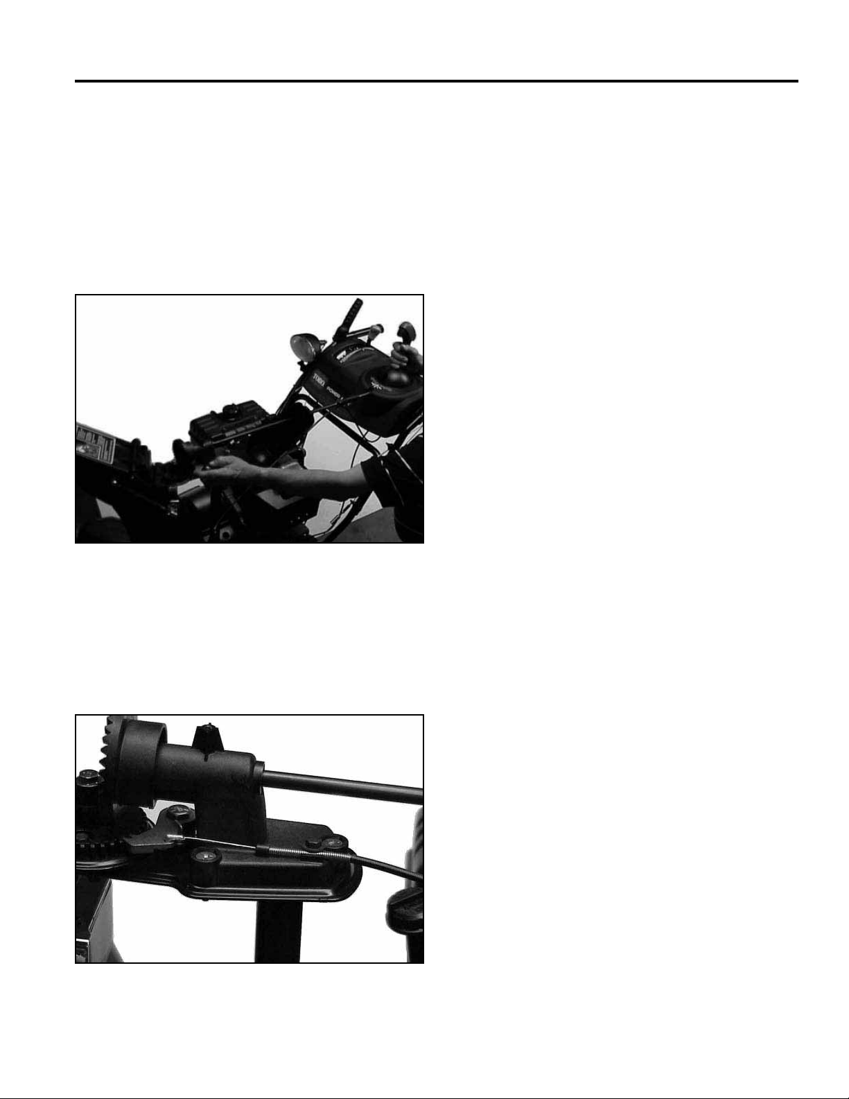
DISCHARGE CHUTE
6. The gear lash for the chute gears must now be
set. No actual measurement is necessary. The
3 shoulder bolts on the face gear mount are in
slotted holes. Push the face gear mount forward
to fully engage in the gears. Snug one or two of
the locknuts, hold the chute latch back and rotate
the chute using the quick stick (Fig. 227). It should
move smoothly. If not move the face gear mount as
needed. Secure the 3 locknuts.
8. Install the gear cover and screw.
Fig 227 MVC-164X
7. Install the end of the latch cable in the latch and
slip the cable under the clamp screw. Pull the cable
to the rear until the latch just begins to move and
tighten the clamp (Fig. 228).
Fig 228 MVC-165X
10-7Power Max Service Manual
Page 90

THIS PAGE INTENTIONALLY LEFT BLANK
10-8 Power Max Service Manual
Page 91

ELECTRICAL
Power Max models have 3 very simple electrical
systems. Each is separate from the other so a problem
in one area will not affect the others.
ELECTRIC START SYSTEM
All models have an electric start system standard. All
4 cycle engines use the Tecumseh electric start system.
See the Tecumseh service manual for repair information.
The 2 cycle models have a Toro system. The 2 Cycle
electric start is covered in the E Engine Service Manual
Form # 492-0647.
LIGHTING
Some 4 cycle models have a light standard or light kit
available. There is no light kit for 2 cycle models.
The lighting system consists of an alternator coil, a wire
leading to the light fi xture and the fi xture itself. This
light operates whenever the engine is running. The
alternator is a Tecumseh part; replacement parts and
troubleshooting assistance are obtained through the
Tecumseh system.
The light fi xture and the wire harness are Toro parts. The
light bulb is replaceable.
The wires run from the ignition coil, under the blower
housing, over the foam pad to the ignition switch. The
other wire runs from the switch to the cylinder head bolt.
Make sure to secure the wires to the primer line with a
wire tie (Fig. 229).
Fig 229 MVC-864X
To test the switch remove the wires and attach a
continuity light or ohmmeter. When the switch is on there
should be no continuity. When the switch is off there
should be continuity between the terminals (Fig. 230).
IGNITION SWITCH
All models have an on/off switch.
On the 4 cycle models the switch is an engine part and
is built into the carburetor heater box, next to the throttle.
Use Tecumseh service information for troubleshooting
and repair.
The 2 cycle models have a simple on/off switch mounted
in the rear engine cover. When the key is turned off, the
switch closes, the magneto primary is grounded to the
engine block and the engine stops. When turned to on,
the ground is disconnected allowing the ignition to fi re.
Fig 230 MVC-192
See the engine section for access to the ignition switch
on 2 cycle models.
11-1Power Max Service Manual
Page 92

THIS PAGE INTENTIONALLY LEFT BLANK
11-2 Power Max Service Manual
Page 93

WHEELS AND TIRES
WHEELS TIRES
There is a difference in the way the wheel is attached to
the axle, depending on the drive system used.
On the standard machine the wheel is connected to the
axle by a click pin. This allows the pin to be removed
from the wheel and just placed in the axle. This makes
the machine free wheel for easy transport. Place the
pin through both the axle and wheel for self propelling
(Fig. 231).
The tires on all models are 15” tubeless X-Trac tires.
They are directional so they must be installed as shown,
looking forward from the operator position (Fig. 233).
Fig 233 MVC-880X1
Correct Tire pressure is 17-20 psi (117-137 kPa).
Fig 231 MVC-184X
On wheel clutch models, the wheel is attached with a
bolt and locknut. The traction drive can be declutched by
squeezing the levers. This provides the declutching for
easy pushing (Fig. 232).
Note: Tire pressure needs to be the same side-to-
side or the machine will tend to pull to the side
with the lower pressure.
Fig 232 MVC-884Xt
12-1Power Max Service Manual
Page 94

THIS PAGE INTENTIONALLY LEFT BLANK
12-2 Power Max Service Manual
Page 95

THIS PAGE INTENTIONALLY LEFT BLANK
Page 96

Power Max™
Service Manual
Form no. 492-9138
 Loading...