

Toro 139-4845 Installation Instructions

DipstickKit
TXL2000ToolCarrier
ModelNo.139-4845
Installation
LooseParts
Usethechartbelowtoverifythatallpartshavebeenshipped.
FormNo.3431-601RevA
InstallationInstructions
Description
Nopartsrequired
Nopartsrequired
Dipstickguide1
Dipstick1
Bolt(M8x12mm)
Cabletie
PreparingtheMachine
1.Parkthemachineonalevelsurface.
2.Removeanyattachments;refertotheOperator’s
Manualforthemachine.
3.Raisetheloaderarmsandsecurethemwith
cylinderlocks.
4.Shutofftheengineandremovethekey.
Qty.
Use
–
–
1
1
Preparethemachine.
Removetheenginepanel.
Installthenewdipstick.
RemovingtheEnginePanel
Note:Reversetheproceduretoinstalltheengine
panelafterinstallingthekit.
1.Openthehood.
2.Removethescrewclampsecuringthehoseto
thehydraulic-tankbreatherontherightsideof
theenginepanel(Figure1).
©2019—TheT oro®Company
8111LyndaleAvenueSouth
Bloomington,MN55420
Registeratwww.T oro.com.
Figure1
1.Hydraulic-tankbreather3.Hose
2.Screwclamp
OriginalInstructions(EN)
PrintedintheUSA
AllRightsReserved
g286600
*3431-601*A
3.Removethehosefromthebreather.
4.Ontheleftsideoftheenginepanel,remove
the2bolts(5/16inch)and2nuts(5/16inch)
securingtheleftgrilleplatetotheenginepanel
(Figure2).
InstallingtheNewDipstick
Note:Theexistingdipstickandguidedoesnotneed
toberemoved.
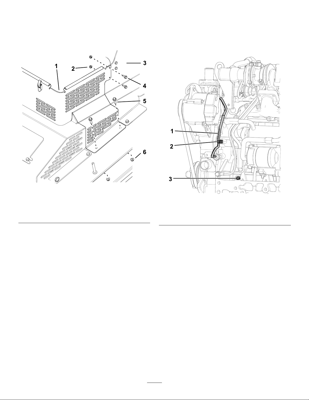
1.Removetheplugontheleftsideoftheengine
(Figure3).
Figure2
1.Enginepanel
2.Nut—5/16inch(2)5.Bolt—3/8inch(2)
3.Leftgrilleplate6.Nut—3/8inch(2)
4.Bolt—5/16inch(2)
5.Removethe2bolts(3/8inch)and2nuts(3/8
inch)securingtheenginepaneltothemain
frameofthemachine(Figure2).
6.Repeatsteps4and5fortherightsideofthe
machine.
7.Removetheenginepanel.
g286599
g286748
Figure3
1.Wireharness3.Plug
2.Cabletie
2.Cutandremovethecabletiesecuringthewire
harnesstotheengine(Figure3).
3.Installthedipstickguideanddipstick(Figure4).
2
 Loading...