

Page 1
FormNo.3422-358RevB
TrimmerMountKit
ZMaster
ModelNo.137-9769
®
3000,5000,or6000SeriesRidingMower
InstallationInstructions
Safety
SafetyandInstructional
Decals
Safetydecalsandinstructionsare
easilyvisibletotheoperatorandare
locatednearanyareaofpotential
danger.Replaceanydecalthatis
damagedormissing.
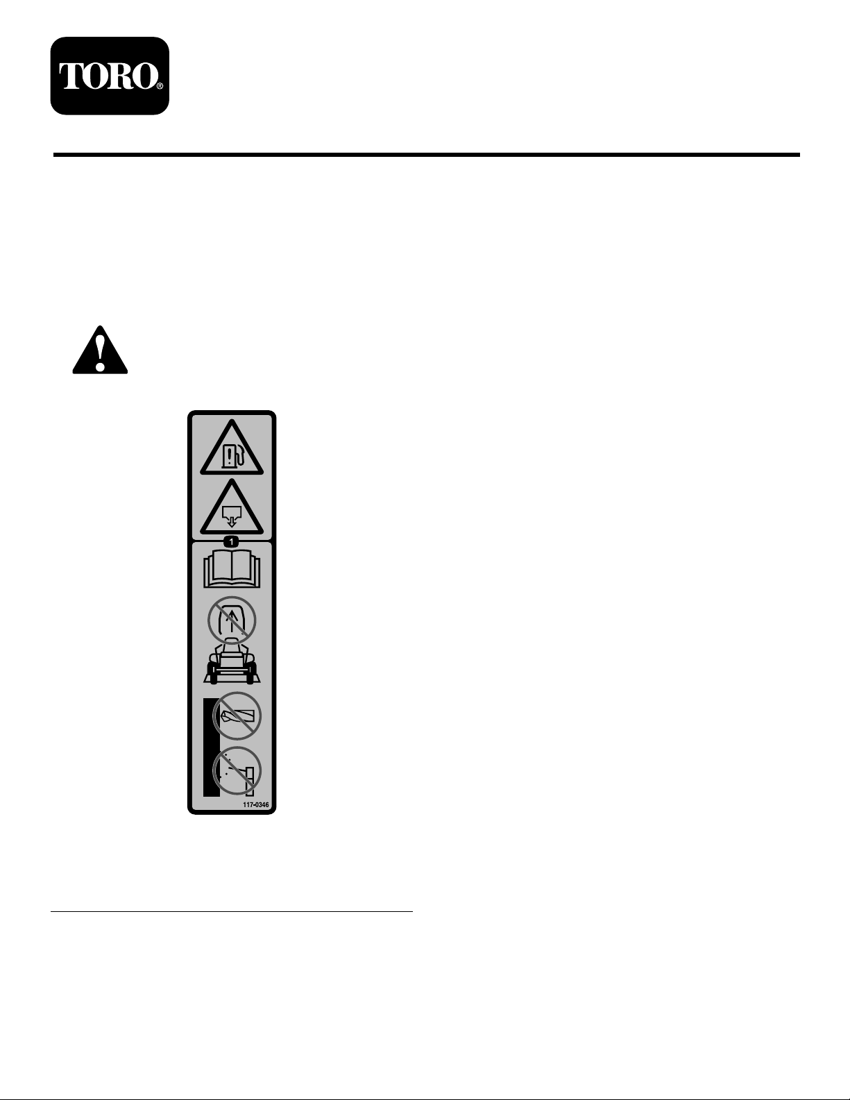
117-0346
1.Fuel-leakhazard—readtheOperator'sManual;donot
attempttoremovetherollbar;donotweld,drill,ormodify
therollbarinanyway .
©2018—TheT oro®Company
8111LyndaleAvenueSouth
Bloomington,MN55420
Registeratwww.T oro.com.
decal117-0346
OriginalInstructions(EN)
PrintedintheUSA
AllRightsReserved
*3422-358*B
Page 2
Installation
1
PreparingtheMachine
NoPartsRequired
Procedure
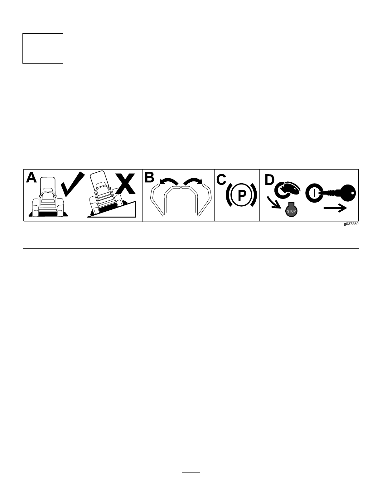
1.Parkthemachineonalevelsurface.
2.Movethemotion-controlleverstotheNEUTRAL-LOCKposition.
3.Engagetheparkingbrake.
4.Shutofftheengineandremovethekey .
Figure1
g037289
2
Page 3
2
3
AssemblingtheUpper TrimmerMountAssembly
Partsneededforthisprocedure:
1Uppertrimmermountbracket
1
Largestclamp
1Largebackerplate
2
Carriagebolt(1/4x1-1/2inches)
2
Flangenut(1/4inch)
Procedure
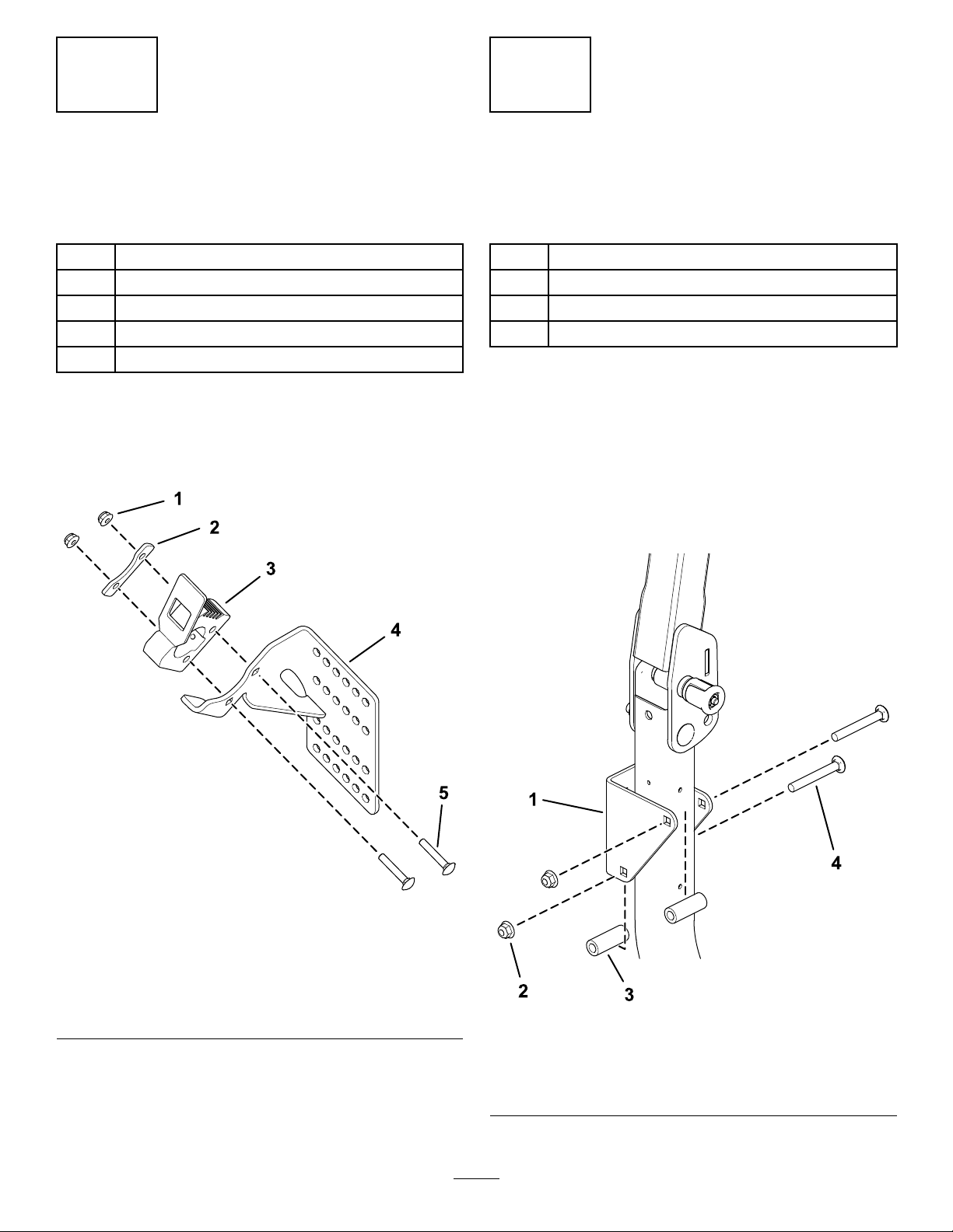
Assembletheuppertrimmermountassembly(Figure
2).
InstallingtheSupport Bracket
Partsneededforthisprocedure:
1
Supportbracket
2Tubespacer
2
Carriagebolt(3/8x3inches)
2
Flangenut(3/8inch)
Procedure
1.Lowertherollbar.
2.Installthesupportbrackettotherightpostofthe
rollbarusing2tubespacers,2carriagebolts
(3/8x3inches),and2angenuts(3/8inch)as
showninFigure3.
3.Raisetherollbar.
1.Flangenut(1/4inch)
2.Largebackerplate
3.Largestclamp
Figure2
4.Uppertrimmermount
bracket
5.Carriagebolt(1/4x1-1/2
inches)
g249810
g248751
Figure3
1.Supportbracket
2.Flangenut(3/8inch)4.Carriagebolt(3/8x3
3
3.Tubespacer
inches)
Page 4
4
5
ApplyingtheDecal
Partsneededforthisprocedure:
1Decal117-0346
Procedure
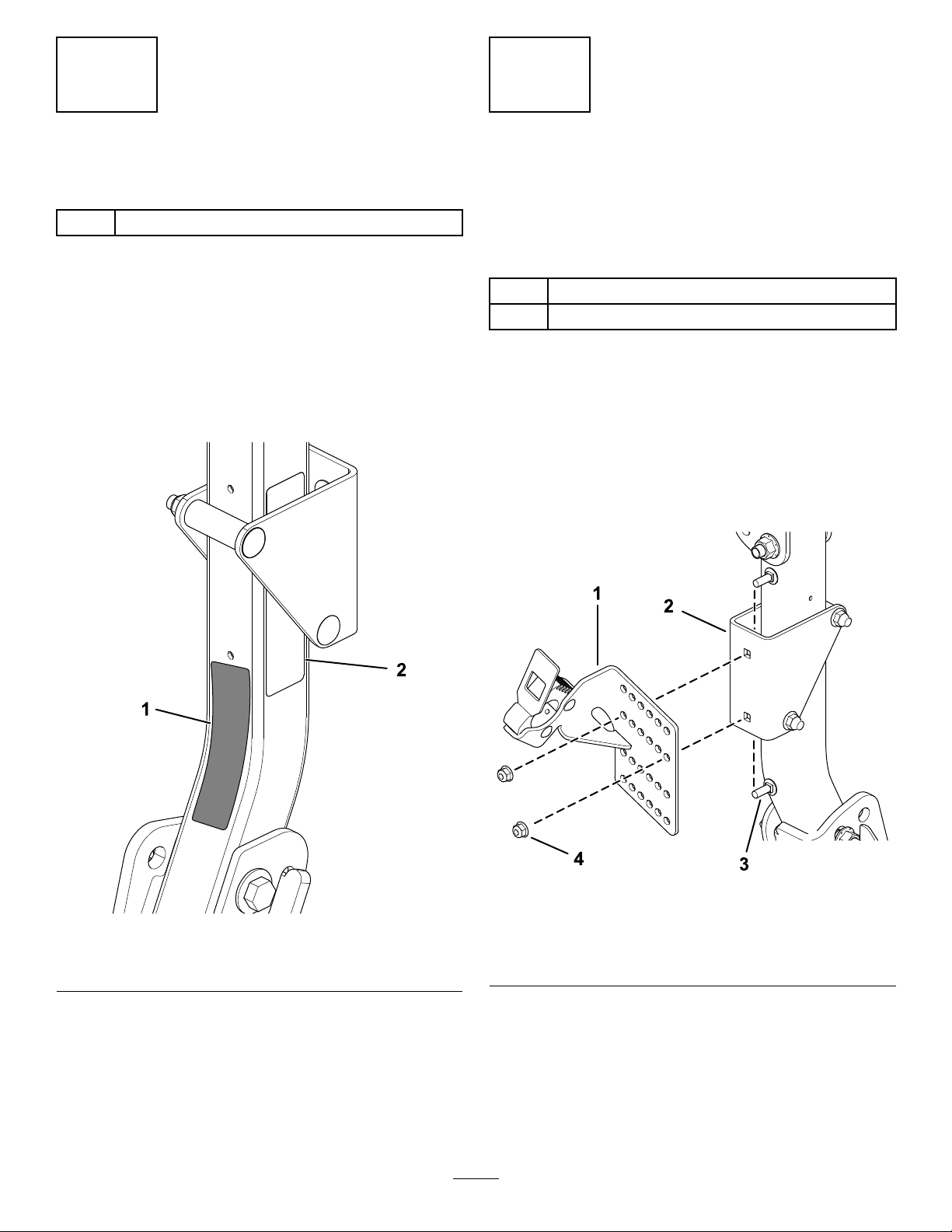
Ifdecal1 17-0346isappliedtotherightpostofthe
rollbaronyourmachineandthesupportbracketnow
coversthatdecal,applythenewdecaltotheinner,
lowersideoftherightpostoftherollbar(Figure4).
Note:Ifdecal117-0346isnotappliedtotheright
postoftherollbaronyourmachine,discardthedecal.
SecuringtheUpper TrimmerMountAssembly totheSupportBracket
Partsneededforthisprocedure:
2
Carriagebolt(5/16x7/8inch)
2
Flangenut(5/16inch)
Procedure
Securetheuppertrimmermountassemblytothe
supportbracketusing2carriagebolts(5/16x7/8inch)
and2angenuts(5/16inch)asshowninFigure5.
Note:Multiplemountingholelocationsareprovided
toadjustthemountingpositionofthetrimmerfor
clearance.
Figure4
1.Applythenewdecalhere.2.Existing,covereddecal
g249811
Figure5
g249924
1.Uppertrimmermount
assembly
2.Supportbracket4.Flangenut(5/16inch)
4
3.Carriagebolt(5/16x7/8
inch)
Page 5
6
7
InstallingtheLower TrimmerMountAssembly
Partsneededforthisprocedure:
1Lowertrimmermountassembly
2
Carriagebolt(3/8x1inch)
2
Flangenut(3/8inch)
Procedure
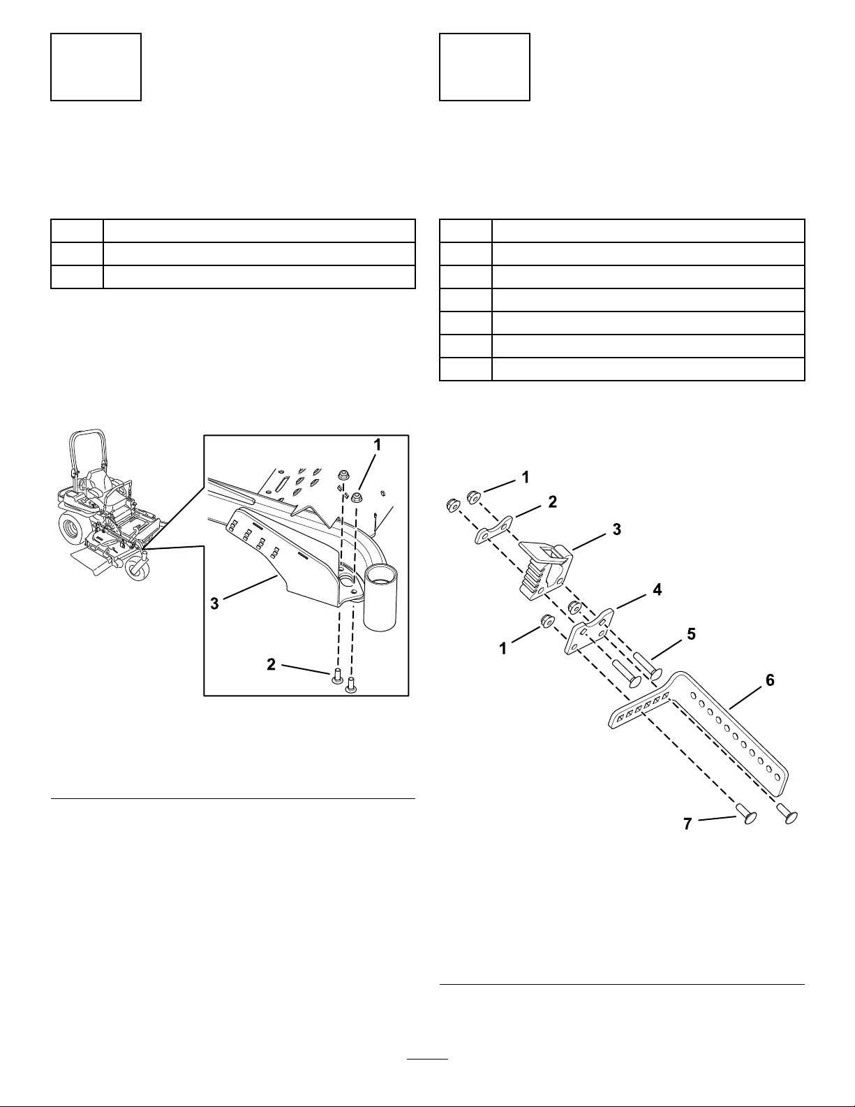
Installthelowertrimmermountassemblytothe
tie-downhookmountinglocationonthefront,right
sideoftheframeusing2carriagebolts(3/8x1inch)
and2angenuts(3/8inch)asshowninFigure6.
AssemblingtheTrimmer MountBracket
Partsneededforthisprocedure:
1Trimmermountbracket
1Fist-mountplate
1
Smallstclamp
1
Smallbackerplate
4
Flangenut(1/4inch)
2
Carriagebolt(1/4x3/4inch)
2
Carriagebolt(1/4x1-1/4inches)
Procedure
Assemblethetrimmermountbracket(Figure7).
1.Flangenut(3/8inch)
2.Carriagebolt(3/8x1inch)
Figure6
3.Lowertrimmermount
assembly
g249903
g248809
Figure7
1.Flangenut(1/4inch)5.Carriagebolt(1/4x1-1/4
2.Smallbackerplate
3.Smallstclamp7.Carriagebolt(1/4x3/4
4.Fist-mountplate
5
inches)
6.Trimmermountbracket
inch)
Page 6
8
9
SecuringtheTrimmer
MountBrackettotheLower
TrimmerMountAssembly
Partsneededforthisprocedure:
2
Carriagebolt(1/4x3/4inch)
2
Flangenut(1/4inch)
Procedure
1.Fullylowerthemowerdeck.
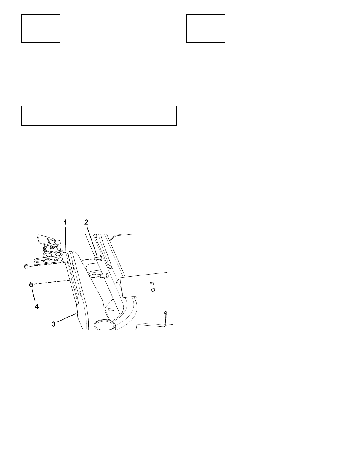
2.Securethetrimmermountbracketassembly
tothelowertrimmermountassemblyusing2
carriagebolts(1/4x3/4inch)and2angenuts
(1/4inch)asshowninFigure8.
Note:Multiplemountingholelocationsare
providedtoadjustthemountingpositionofthe
trimmerforclearance.
SecuringaTrimmertothe MountAssemblies
NoPartsRequired
Procedure
Insertthehandleendofthetrimmerintothelargest
clampandthetrimmingendintothesmallstclamp.
Checkthetofthetrimmerforinterference,and
adjustthemountingholelocationsasrequiredfor
clearancetothemachine.
Figure8
1.Trimmermountbracket3.Lowertrimmermount
2.Carriagebolt(1/4x3/4
inch)
assembly
4.Flangenut(1/4inch)
g248811
6
Page 7

Notes:
Page 8

 Loading...