

Toro 131-4183 Installation Instructions
Installation
LooseParts
FormNo.3392-355RevB
42inRecycler
TimeCutter
ModelNo.131-4183
®
MXSeriesRidingMower
®
Kit
InstallationInstructions
WARNING
CALIFORNIA
Proposition65Warning
ThisproductcontainsachemicalorchemicalsknowntotheStateofCaliforniato
causecancer,birthdefects,orreproductiveharm.
Usethechartbelowtoverifythatallpartshavebeenshipped.
ProcedureDescription
1
2
3
4
Nopartsrequired
Nopartsrequired
Bafeassembly
Kicker1
Flangenut(5/16inch)
Carriagebolt(5/16x3/4inch)
Kickerplate1
Self-tappingscrew(5/16x3/4inch)
Decal1
Mulchingmowerblade2Installthebladesandmower.
WARNING
Whilemaintenanceoradjustmentsarebeingmade,
someonecouldstarttheengine.Accidentalstarting
oftheenginecouldseriouslyinjureyouorother
bystanders.
Qty.
–
–
1
6
1
2
1
PreparingtheMower
Use
Preparethemower.
Removetheblades.
Installthekit.
Removethekeyfromtheignitionswitch,engage
parkingbrake,andpullthewiresoffthesparkplugs
beforeyoudoanymaintenance.Pushthewires
asidesotheydonotaccidentallycontactthespark
plugs.
©2014—TheT oro®Company
8111LyndaleAvenueSouth
Bloomington,MN55420
Registeratwww.T oro.com.
NoPartsRequired
Procedure
1.Stoptheengineandremovetheignitionkey.
2.RemovethemowerasdescribedinyourOperator's
Manual.
3.Turnthemowerupsidedown.
OriginalInstructions(EN)
PrintedintheUSA
AllRightsReserved
*3392-355*B
4.Removeanydebrisandgrassclippingsfromthe
G01801 1
1
undersideofthedeck.
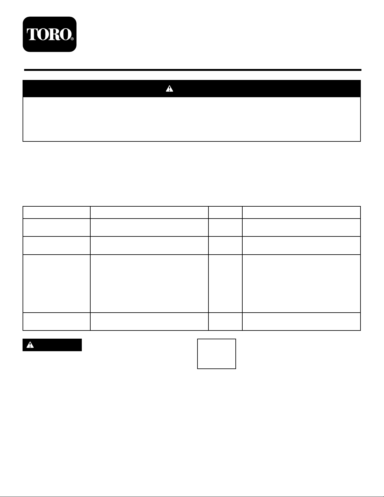
5.Locatethecutoffbafeattheside-dischargeopening
onthemowerdeck(Figure1).
Figure1
1.Cutoffbafe(existing)
6.Removethefastenersthatsecurethecutoffbafeto
thedeck,andremovethecutoffbafe.
yourmower.Holdthebladeendusingaragor
thickly-paddedgloveandremovethebladeasshown.
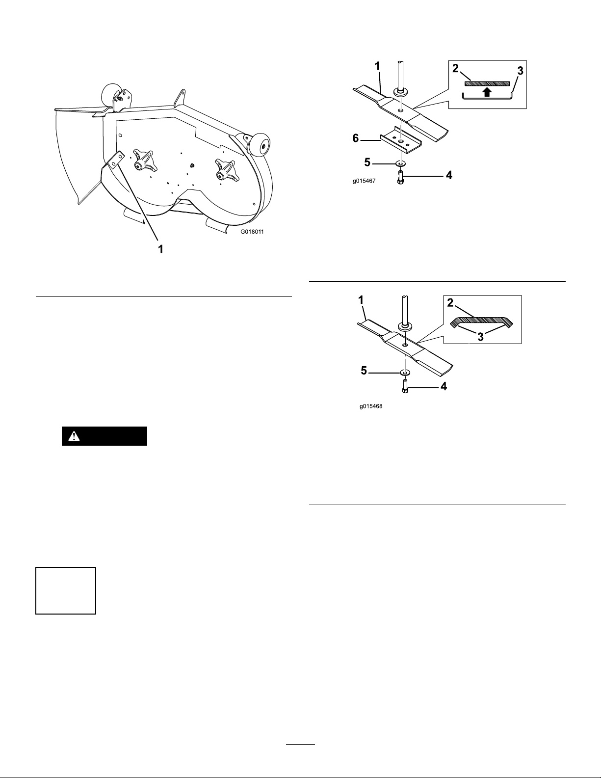
Figure2
BladestyleAmountingconguration
1.BladestyleA4.Bladebolt
2.Crosssectionofblade
styleA
3.Bladestiffenerrequired6.Bladestiffener
5.Curvedwasher
Note:Savethecutoffbafeforconvertingthemower
deckbacktoside-discharging.
7.Installthefastenersintothesameholesinthedeck
fromwhichtheywereoriginallyremoved.
Note:Thisensuresthatnoholesareleftopenwhen
youoperatethedeck.
DANGER
Openholesinthemowerdeckexposeyouand
otherstothrowndebris.Debristhrownoutof
theholesinthemowerdeckcancauseinjury.
•Neveroperatethemowerdeckwithout
hardwaremountedinallholesinthe
mowerdeck.
•Installhardwareinthemountingholes
whenyouremovethebafe.
2
Figure3
BladestyleBmountingconguration
1.BladestyleB4.Bladebolt
2.Crosssectionofblade
styleB
3.Bendsaddextrastiffness
2.Thereplacementbladeswithinthiskitdonotneeda
stiffener.Ifyouremovedone,keepitincasefuture
replacementbladesrequireit.
5.Curvedwasher
RemovingtheBlades
NoPartsRequired
Procedure
1.Choosethestyleofblade,ofthoseshowninFigure
2andFigure3thatbestmatchesthebladeson
2
3
G018014
1
2
G018015
1
InstallingtheKit
Partsneededforthisprocedure:
1
Bafeassembly
1Kicker
6
Flangenut(5/16inch)
1
Carriagebolt(5/16x3/4inch)
1Kickerplate
2
Self-tappingscrew(5/16x3/4inch)
1Decal
Procedure
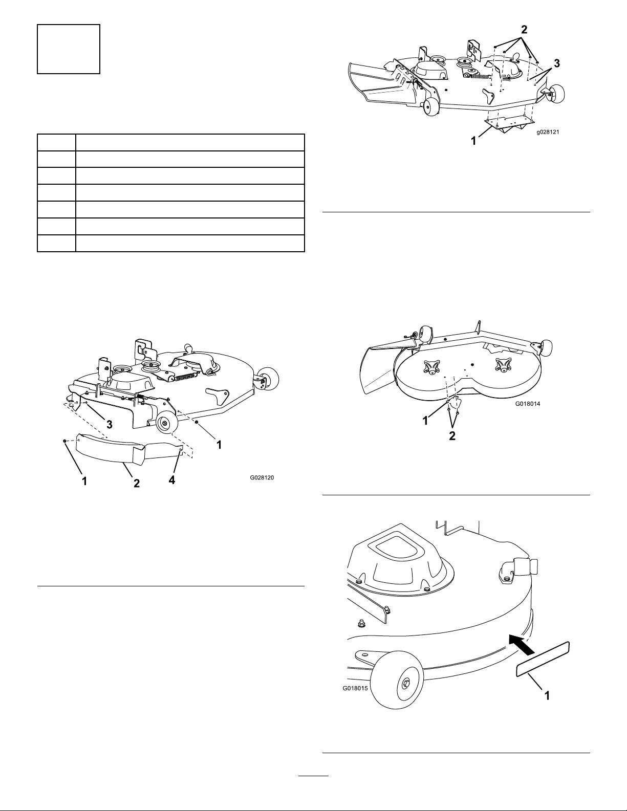
1.Installthebafeassemblytotheright-handsideofthe
mowerdeckwithacarriagebolt(5/16x3/4inch)and
2angenuts(5/16inch)asshowninFigure4.
Figure5
1.Kickerplate3.Remove2plugboltsand
2nutshere.
2.Flangenut(5/16inch)(4)
3.Securethekickerplatetotheleft-handsideofthe
mowerdeckusing4angenuts(5/16inch)asshown
inFigure5.
4.Tightenallfasteners.
5.Installthekickertotheundersideofthemowerdeck
using2self-tappingscrews(5/16x3/4inch)atthe
locationshowninFigure6.
Figure4
Theside-dischargechutehasbeenremovedforthe
purposeofclarity.
1.Flangenut(5/16inch)3.Carriagebolt(5/16x3/4
2.Bafeassembly
inch)
4.Weldedpost
Note:Handtightenthefasteners.
2.Remove2plugboltsand2nutsfromthemowerdeck
inthelocationsshowninFigure5.
Figure6
1.Kicker
2.Self-tappingscrews(5/16
x3/4inch)
6.InstallthedecaltotheareashowninFigure7.
Figure7
1.Decal
3
 Loading...